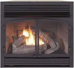
VENT-FREE GAS FIREPLACE
INSERT
OWNER’S OPERATION AND
INSTALLATION MANUAL
MODEL FDF300R
SKU #170032
PFS
®
US
WARNING: If the information in this manual is not
followed exactly, a re or explosion may result causing
property damage, personal injury or loss of life.
— Do not store or use gasoline or other ammable va-
pors and liquids in the vicinity of this or any other
appliance.
— WHAT TO DO IF YOU SMELL GAS
• Do not try to light any appliance.
• Do not touch any electrical switch; do not use any
phone in your building.
•
Immediately call your gas supplier from a neighbor’s
phone. Follow the gas supplier’s instructions.
• If you cannot reach your gas supplier, call the re
department.
—
Installation and service must be performed by a quali-
ed installer, service agency or the gas supplier.
WARNING: This appliance is equipped for Natural and
Propane gas. Field conversion is not permitted other than
between natural or propane gases.
This insert can be used in the mantel and
replace systems CM300-1
Questions, problems, missing parts? Before returning to your retailer, call
our customer service department at 1-855-607-6557, 8:00 am - 4:30 pm EST,
Monday through Friday or email info@factorybuysdirect.com
www.factorybuysdirect.com
200253-01D2
TABLE OF CONTENTS
Safety ........................................................ 3
Specications ............................................ 4
Qualied Installing Agency ........................ 5
Product Features ....................................... 5
Local Codes............................................... 5
Unpacking.................................................. 5
Air For Combustion and Ventilation ........... 6
Product Identication ................................. 6
Water Vapor: A By-Product Of
Unvented Room Heaters ..................... 6
Installation ................................................. 8
Operation ................................................. 19
Inspecting Burners................................... 23
Care And Maintenance ............................ 24
Electrical .................................................. 26
Troubleshooting ....................................... 28
Service Hints ........................................... 31
Technical Service..................................... 31
Parts ........................................................ 32
Replacement Parts .................................. 34
Accessories ............................................. 35
Warranty .................................................. 36
INSTALLER: Leave this manual with the appliance.
CONSUMER: Retain this manual for future reference.
This is an unvented gas-red heater. It uses air (oxygen)
from the room in which it is installed. Provisions for ad-
equate combustion and ventilation air must be provided.
Refer to Air For Combustion and Ventilation section on
page 6 of this manual.
WARNING: Improper installation, adjustment, al-
teration, service or maintenance can cause injury or
property damage. Refer to this manual for correct in-
stallation and operational procedures. For assistance
or additional information consult a qualied installer,
service agency or the gas supplier.
This appliance may be installed in an aftermarket,* per-
manently located, manufactured (mobile) home, where
not prohibited by local codes.
This appliance is only for use with propane or natural
gas. Field conversion by any other means including the
use of a kit is not permitted.
* Aftermarket: Completion of sale, not for purpose of resale, from the manufacturer.
SAVE THIS BOOK
PATENT INFORMATION
This product may be covered by one or more of the following United States patents:
8,915,239 8,851,065 8,764,436 8,757,202 8,757,139 8,752,541 8,568,136
8,545,216 8,517,718 8,516,878 8,506,290 8,465,277 8,317,511 8,297,968
8,281,781 8,241,034 8,235,708 8,152,515 8,011,920 7,967,006 7,967,007
7,654,820 7,730,765 7,677,236 7,607,426 7,434,447
www.factorybuysdirect.com
3200253-01D
SAFETY
IMPORTANT: Read this owner’s
manual carefully and completely
before trying to assemble, op-
erate, or service this heater.
Improper use of this heater can
cause serious injury or death
from burns, fire, explosion,
electrical shock and carbon
monoxide poisoning. Failure
to follow these instructions will
void the warranty.
Only a qualied installer, service
agent, or local gas supplier may
install and service this product.
WARNING: Keep the appli-
ance area clear and free from
combustible materials, gasoline,
and other ammable vapors and
liquids.
WARNING: This appliance
can be used with propane or
natural gas. It is shipped from
the factory adjusted for use with
propane.
DANGER: Carbon monoxide
poisoning may lead to death!
CARBON MONOXIDE POISONING: Early
signs of carbon monoxide poisoning resemble
the u, with headaches, dizziness or nausea.
If you have these signs, the heater may not be
working properly. Get fresh air at once! Have
heater serviced. Some people are more af-
fected by carbon monoxide than others. These
include pregnant women, people with heart or
lung disease or anemia, those under the inu-
ence of alcohol and those at high altitudes.
NATURAL AND PROPANE/LP GAS: Natural
and Propane/LP gas are odorless. An odor-
making agent is added to the gas. The odor
helps you detect a gas leak. However, the
odor added to the gas can fade. Gas may be
present even though no odor exists.
WARNING: Any change to
this heater or its controls can
be dangerous.
WARNING: Do not allow fans
to blow directly into replace.
Avoid any drafts that alter burner
ame patterns.
WARNING: Do not use a
blower insert, heat exchange
insert or other accessory not
approved for use with this heater.
WARNING: Due to high tem-
peratures, the appliance should
be located out of trafc and away
from furniture and draperies.
WARNING: Do not place
clothing or other flammable
material on or near the appli-
ance. Never place any objects
in the heater.
WARNING: Heater becomes
very hot when running. Keep
children and adults away from
hot surfaces to avoid burns or
clothing ignition. Fireplace will
remain hot for a time after shut-
down. Allow surfaces to cool
before touching.
WARNING: Carefully super-
vise young children when they
are in the room with the heater.
WARNING: You must operate
this heater with screen in place.

www.factorybuysdirect.com
200253-01D4
1. Do not place Propane/LP supply tank(s)
inside any structure. Propane/LP supply
tank(s) must be placed outdoors.
2. This heater shall not be installed in a
bedroom or bathroom.
3. This heater needs fresh air ventilation to
run properly. This heater has an Oxygen
Depletion Sensing (ODS) safety shutoff
system. The ODS shuts down the heater
if not enough fresh air is available. See
Air for Combustion and Ventilation, pages
6 and 7. If heater keeps shutting off, see
Troubleshooting, page 28.
4. Keep all air openings in front and bottom
of heater clear and free of debris. This will
ensure enough air for proper combustion.
5. If heater shuts off, do not relight until you
have provided fresh, outside air. If heater
keeps shutting off, have it serviced.
6. Do not run heater:
• Where ammable liquids or vapors are
used or stored.
• Under dusty conditions.
7. Before using furniture polish, wax, carpet
cleaner, or similar products, turn heater
off. If heated, the vapors from these prod-
ucts may create a white powder residue
within burner box or on adjacent walls or
furniture.
8. Always run heater with control knob at
PILOT or ON locked positions. Never set
control knob between locked positions.
Poor combustion and higher levels of
carbon monoxide may result.
SAFETY
9. Do not use heater if any part has been
under water. Immediately call a qualied
service technician to inspect the room
heater and to replace any part of the
control system and any gas control which
has been under water.
10. Turn off and unplug heater and let cool
before servicing. Only a qualied service
person should service and repair heater.
11. Operating heater above elevations of
4,500 feet could cause pilot outage.
12. To prevent performance problems, do
not use propane/LP fuel tank of less than
100 lbs. capacity.
13. Do not use this heater as a wood-burning
heater. Use only the logs provided with the
heater.
14. To prevent sooting, follow the instructions
in Care and Maintenance (see page 24).
15. Do not add extra logs or ornaments such
as pine cones, vermiculite, or rock wool.
Using these added items can cause soot-
ing. Do not add lava rock around base.
Rock and debris could fall into the control
area of heater. After servicing, always
replace screen before operating heater.
16. This heater is designed to be smokeless. If
logs ever appear to smoke, turn off heater
and call a qualied service person.
Note: During initial operation, slight smok-
ing could occur due to log curing and the
heater burning manufacturing residues.
SPECIFICATIONS
Model FDF300R
Gas Type Natural Gas Propane Gas
Ignition Piezo Ignitor Piezo Ignitor
Input Rating
26,000 Btu/Hr 26,000 Btu/Hr
Pressure Regulator Setting 4" W.C. 9.5" W.C.
Inlet Gas Pressure* (inches of water)
(*for purposes of input adjustment)
Maximum 9" Maximum 14"
Minimum 5" Minimum 11"
Heater Dimensions (WxHxD) •
29.1" × 23.9" × 13.9"
Carton Dimensions (WxHxD) •
30.9" × 26.9" × 14.8"
Stove Weight • 47.6 lbs
Shipping Weight • 55.7 lbs

www.factorybuysdirect.com
5200253-01D
QUALIFIED INSTALLING AGENCY
Only a qualied agency should install and
replace gas piping, gas utilization equipment
or accessories, and repair and equipment ser-
vicing. The term “qualied agency” means any
individual, rm, corporation, or company that
either in person or through a representative
is engaged in and is responsible for:
a) Installing, testing, or replacing gas piping
or
b) Connecting, installing, testing, repairing,
or servicing equipment; that is experienced
in such work; that is familiar with all precau-
tions required; and that has complied with
all the requirement of the authority having
jurisdiction.
PRODUCT FEATURES
SAFETY PILOT
This heater has a pilot with an Oxygen Deple-
tion Sensing (ODS) safety shutoff system. The
ODS/pilot shuts off the heater if there is not
enough fresh air.
PIEZO IGNITION SYSTEM
This heater is equipped with an electronic
piezo control system. This system requires
one AAA battery (provided).
THERMOSTATIC CONTROL
The control automatically cycles the burner
on and off to maintain a desired room
temperature.
2 GAS OPTIONS AVAILABLE
Your heater is equipped to operate on either
Propane/LP or Natural gas. The heater is
shipped from the factory ready for connect-
ing to Propane/LP. The heater can easily be
changed to Natural gas by having your quali-
ed installer follow the instructions on page
10 and the markings on the heater.
LOCAL CODES
Install and use heater with care. Follow all
local codes. In the absence of local codes,
use the latest edition of The National Fuel
Gas Code, ANSI Z223.1/NFPA 54*.
*Available from:
American National Standards Institute, Inc.
1430 Broadway
New York, NY 10018
National Fire Protection Association, Inc.
1 Batterymarch Park
Quincy, MA 02269-9101
This heater is designed for vent-free op-
eration. State and local codes in some areas
prohibit the use of vent-free heaters.
State of Massachusetts: The installation
must be made by a licensed plumber or
gas tter in the Commonwealth of Mas-
sachusetts.
Sellers of unvented propane or natural
gas-red supplemental room heaters shall
provide to each purchaser a copy of 527
CMR 30 upon sale of the unit.
In the State of Massachusetts the gas
cock must be a T-handle type. The State
of Massachusetts requires that a exible
appliance connector cannot exceed three
feet in length.
UNPACKING
1. Remove top inner pack.
2. Tilt carton so that heater is upright.
3. Remove protective side packaging.
4. Slide heater out of carton.
5 Remove protective plastic wrap.
6. Hold the screen, lift, and pull forward.
7. Remove log set by cutting plastic ties.
8. Carefully unwrap log.
9. Check for any shipping damage. If heater
or log is damaged, promptly inform your
dealer where you bought the heater.
10. Remove four screws and two bottoms of
angle iron.
www.factorybuysdirect.com
200253-01D6
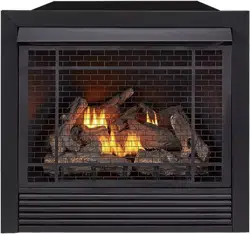
PRODUCT IDENTIFICATION
Figure 1 - Vent-Free Fireplace Insert
Hood
Logs
Screen
Heater Controls
(Behind Panel)
WATER VAPOR: A BY-PRODUCT OF
UNVENTED ROOM HEATERS
Water vapor is a by-product of gas combus-
tion. An unvented room heater produces ap-
proximately one (1) ounce (30 mL) of water
for every 1,000 BTUs (0.3 KWs) of gas input
per hour. Unvented room heaters are recom-
mended as supplemental heat (a room) rather
than a primary heat source (an entire house).
In most supplemental heat applications, the
water vapor does not create a problem. In
most applications, the water vapor enhances
the low humidity atmosphere experienced
during cold weather.
The following steps will help ensure that water
vapor does not become a problem.
1. Be sure the heater is sized properly for the
application, including ample combustion
air and circulation air.
2. If high humidity is experienced, a dehu-
midier may be used to help lower the
water vapor content of the air.
3. Do not use an unvented room heater as
the primary heat source.
Screw
Angle
Iron
AIR FOR COMBUSTION AND VENTILATION
WARNING: This heater shall
not be installed in a conned space
or unusually tight construction
unless provisions are provided
for adequate combustion and
ventilation air. Read the following
instructions to insure proper fresh
air for this and other fuel-burning
appliances in your home.
Today’s homes are built more energy efcient
than ever. New materials, increased insulation
and new construction methods help reduce
heat loss in homes. Home owners weather
strip and caulk around windows and doors
to keep the cold air out and the warm air in.
During heating months, home owners want
their homes as airtight as possible.
While it is good to make your home energy
efcient, your home needs to breathe. Fresh
air must enter your home. All fuel-burning ap-
pliances need fresh air for proper combustion
and ventilation.

www.factorybuysdirect.com
7200253-01D
Exhaust fans, replaces, clothes dryers and
fuel burning appliances draw air from the house
to operate. You must provide adequate fresh
air for these appliances. This will insure proper
venting of vented fuel-burning appliances.
WARNING: This heater shall
not be installed in a room or
space unless the required vol-
ume of indoor combustion air
is provided by the method de-
scribed in the National Fuel Gas
Code, ANSI Z223.1/NFPA 54, the
International Fuel Gas Code, or
applicable local codes.
WARNING: If the area in which
the heater may be operated does
not meet the required volume for
indoor combustion air, combus-
tion and ventilation air shall be
provided by one of the methods
described in the National Fuel
Gas Code, ANSI Z223.1/NFPA 54,
the International Fuel Gas Code,
or applicable local codes.
VENTILATION AIR
AIR FOR COMBUSTION AND VENTILATION
Outlet
Air
Ventilated
Attic
Outlet
Air
Inlet
Air
Inlet Air
Ventilated
Crawl Space
To
Crawl
Space
To Attic
Figure 2 - Ventilation Air from Inside
Building
Figure 3 - Ventilation Air from Outdoors
Or
Remove
Door into
Adjoining
Room,
Option 3
Ventilation Grills
Into Adjoining Room,
Option 2
12"
12"
Ventilation
Grills
into Adjoining
Room,
Option 1
Ventilation Air From Inside Building
This fresh air would come from an adjoining
unconned space. When ventilating to an
adjoining unconned space, you must provide
two permanent openings: one within 12" of the
ceiling and one within 12" of the oor on the
wall connecting the two spaces (see options
1 and 2, Figure 2). You can also remove door
into adjoining room (see option 3, Figure 2).
Follow the National Fuel Gas Code, ANSI
Z223.1/NFPA 54, Air for Combustion and
Ventilation for required size of ventilation
grills or ducts.
Ventilation Air From Outdoors
Provide extra fresh air by using ventilation
grills or ducts. You must provide two perma-
nent openings: one within 12" of the ceiling
and one within 12" of the oor. Connect these
items directly to the outdoors or spaces open
to the outdoors. These spaces include attics
and crawl spaces. Follow the National Fuel
Gas Code, ANSI Z223.1/NFPA 54, Air for
Combustion and Ventilation for required size
of ventilation grills or ducts.
IMPORTANT: Do not provide openings
for inlet or outlet air into attic if attic has a
thermostat-controlled power vent. Heated air
entering the attic will activate the power vent.
Rework worksheet, adding the space of the
adjoining unconned space. The combined
spaces must have enough fresh air to supply
all appliances in both spaces.

www.factorybuysdirect.com
200253-01D8
INSTALLATION
NOTICE: This heater is intended
for use as supplemental heat.
Use this heater along with your
primary heating system. Do not
install this heater as your pri-
mary heat source. If you have a
central heating system, you may
run system’s circulating blower
while using heater. This will help
circulate the heat throughout the
house. In the event of a power
outage, you can use this heater
as your primary heat source.
WARNING: A qualied ser-
vice person must install heater.
Follow all local codes.
WARNING: Never install the
heater
• in a bedroom or bathroom
• in a recreational vehicle
• where curtains, furniture,
clothing, or other ammable
objects are less than 36" from
the front, top, or sides of the
heater
• in high trafc areas
• in windy or drafty areas
CAUTION: This heater cre-
ates warm air currents. These
currents move heat to wall sur-
faces next to heater. Installing
heater next to vinyl or cloth wall
coverings or operating heater
where impurities (such as to-
bacco smoke, aromatic candles,
cleaning uids, oil or kerosene
lamps, etc.) in the air exist, may
cause walls to discolor.
IMPORTANT: Vent-free heaters add moisture
to the air. Although this is benecial, installing
heater in rooms without enough ventilation air
may cause mildew to form too much moisture.
See Air for Combustion and Ventilation, pages
6 and 7.
CHECK GAS TYPE
Be sure your gas supply is right for your heat-
er. Otherwise, call dealer where you bought
the heater for proper type heater.
www.factorybuysdirect.com
9200253-01D
Connector End
of Adapter
Power
Change
Assembly
Back of
Fireplace
Insert
Figure 4 - Connecting to Power Supply
INSTALLATION
CLEARANCES TO COMBUSTIBLES
Figure 5 - Minimum Clearances to Wall
and Ceiling
Ceiling
6"
Min.
6"
Min.
36"
Min.
Side
Wall
Side
Wall
Front View
WARNING: You must main-
tain the minimum clearances
shown in Figure 5. If you can,
provide greater clearances from
oor, ceiling, and joining wall.
Measure from outermost point
of heater.
Minimum Wall and Ceiling
Clearances
A. Clearances from outermost point of heater
to any combustible side wall should not be
less than 6".
B. Clearances from the heater to the ceiling
should not be less than 36".
Note: When heater is installed directly on
carpeting, tile or other combustible material,
other than wood ooring, the heater must be
installed on a metal or wood panel extending
the full width and depth of the heater.
CONNECTING ELECTRICAL
SUPPLY
This replace insert requires an 120V electri-
cal outlet within 4 feet of the unit. There is a
power supply for the remote receiver located
in the bottom of the replace insert. Exten-
sions cords may be used.
The remote receiver requires 4 AA batteries.
This powers the stove in case of an electrical
power outage.
1. Locate 6V DC adapter.
2. Plug connector end of adapter into the
power change assembly on the back of
the replace insert.
3. Plug adapter into a 120V electrical outlet.
www.factorybuysdirect.com
200253-01D10
INSTALLATION
Yellow Natural Gas
Plunger Underneath
Metal Cap
Blue Propane/LP
Gas Plunger
Underneath Dust
Cover
Figure 6 - Gas Regulator
Insert Gas Fitting
for Natural Gas
Insert Gas Fitting
for Propane/LP Gas
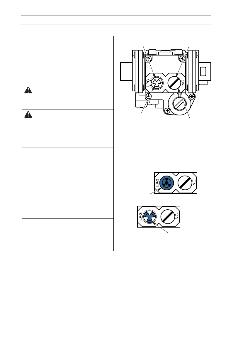
GAS SELECTION
This appliance is factory
preset for propane/LP gas.
No changes are required for
connecting to propane/LP.
Only a qualied installer or service
technician can perform gas selec-
tion and connecting to gas supply.
CAUTION: Two gas line in-
stallations at the same time are
prohibited.
CAUTION: To avoid gas leak-
age for the gas not being used at
the inlet of regulator, a qualied
installer or service technician
must use supplied cap.
You will notice a color coded
plunger on the inside of the regu-
lator. This is normal. When the in-
let connection tting is inserted
and tightened, this plunger will
be pushed back by the tting
making all of the adjustments
for the gas being supplied. DO
NOT REMOVE THE PLUNGER.
The regulator will not work.
The inlet regulator is color coded
for identication of the correct
gas type. Blue is for propane (LP
gas) and yellow is for natural gas.
Blue Dust
Cover
DO NOT REMOVE
Blue Propane/LP Plunger
Install Gas Fitting Here
FOR PROPANE/LP GAS
INSTALLATION: BLUE
1. Remove blue dust cover.
www.factorybuysdirect.com
11200253-01D
INSTALLATION
Use only the cap supplied on the
regulator. Do not use an off the
shelf pipe plug. This can damage
the plunger. The supplied regula-
tor cap is designed so it will not
engage the unused gas type.
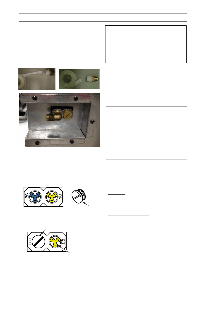
4. Apply thread sealant to the threads on
the connection tting. While pushing in,
rotate the tting clockwise until the threads
engage the regulator. After the tting has
been hand tightened into the regulator
use a wrench to complete tightening of the
tting. Install additional tting to connect
to the house supply.
DO NOT use an off the shelf 3/8"
NPT pipe plug. This will damage
the plungers located inside the
regulator.
DO NOT try to remove the plung-
ers from inside the regulator. The
plunger will be pushed back as
the tting is installed.
Make sure the type of gas being
used is correct. Check to make
sure the connection tting is in
the correct inlet on the regula-
tor. Refer to Connecting to Gas
Supply, page 14.
If you are using natural gas
and the pilot will not light, see
Troubleshooting, page 28.
Metal Cap
Metal Cap
DO NOT REMOVE
Yellow Natural Gas Plunger
Install Gas Fitting Here
2. Apply thread sealant to the threads on
the connection tting. While pushing in,
rotate the tting clockwise until the threads
engage the regulator. After the tting has
been hand tightened into the regulator
use a wrench to complete tightening of the
tting. Install additional tting to connect
to the house supply.
FOR NATURAL GAS (NG)
INSTALLATION: YELLOW
1. Remove the blue dust cover from the
regulator.
2. Remove the metal cap installed over the
NG regulator inlet.
3. Install metal cap over LP/Propane regulator
inlet. This will keep debris out of regulator.
www.factorybuysdirect.com
200253-01D12
INSTALLATION
Figure 9 - Rough Opening for Wall
Installation
Figure 7 - Clearance to Combustibles
Figure 8 - Fireplace Clearances
3/4" Clearance to Facia
Note: Height of fireplace opening on facia to be 23
1
/
4
"
1
3
/
8
" Clearance to Sides, Back and Top
27
3
/
4
"
28
3
/
4
"
13"
16"
19"
21"
10"
8"
6"
2
1
/
2
"
Side of
Firebox
Mantel
Shelf
Note: All vertical
measurements
are from top of
fireplace
opening to
bottom of
mantel shelf. All
measurements
are in inches.
23.25"
12.75"
28.75"
BUILT-IN FIREPLACE INSTALLATION
WARNING: Do not allow any
combustible materials to overlap
the rebox front.
WARNING: Do not allow
combustible or noncombustible
materials to cover any necessary
openings like louvered slots.
WARNING: Never modify or
cover the louvered slots on the
front of the rebox.
Built-in installation of this replace involves
installing replace into a framed-in enclosure.
This makes the front of the replace ush
with wall. If installing a built-in mantel above
the replace, you must follow the clearances
shown in Figure 7.
NOTICE: Surface temperatures
of adjacent walls and mantels
become hot during operation.
Walls and mantels above the
replace may become hot to the
touch. If installed properly, these
temperatures meet the require-
ment of the national product
standard. Follow all minimum
clearances shown in this manual
(see Figure 8).
1. Frame in rough opening. Use dimensions
shown in Figure 9 for the rough opening.
If installing in a corner, use dimensions
shown in Figure 10 (page 13) for the rough
opening. The height is 26
1
/
2
", which is the
same as the wall opening above.
2. Carefully set replace in front of rough
opening with back of replace inside wall
opening.
www.factorybuysdirect.com
13200253-01D
INSTALLATION
Figure 11 - Hood Installation
Remove 2
Screws from Top
Firebox Panel
Insulation
Board
Replace 2
Screws
Hood
Step 1
Step 2
Step 3
Figure 10 - Rough Opening for Corner
Installation
37.4"
28.75"
53.8"
26.5"
3. Attach gas line to replace gas regulator.
See Connecting to Gas Supply, page 14.
4. Check all gas connections for leaks. See
Checking Gas Connections, page 16.
IMPORTANT: When nishing your rebox,
combustible materials such as wall board,
gypsum board, sheet rock, drywall, plywood,
etc, must have 1/2" clearance to the sides
and top of the rebox. Combustible materials
should never overlap the rebox front.
ASSEMBLING HOOD
CAUTION: Do not operate
replace without hood in place.
1. Fireplace hood is positioned on top of
shipping inner pack.
2. Remove top of rebox by removing 2 screws
located on each end (see Figure 11).
3. Insert the hood along the upper side of
the heat insulation board (see Figure 11).
Attach hood with 3 screws.
4. Reattach rebox top by reinserting the 2
screws from step 2.
www.factorybuysdirect.com
200253-01D14
INSTALLATION
CONNECTING TO GAS SUPPLY
CAUTION: Avoid damage to
regulator. Hold gas regulator
with wrench when connecting
into gas piping and/or ttings.
CAUTION: Use pipe joint
sealant that is resistant to gas
(Propane/LP or Natural Gas).
Before installing heater, make sure you have
the items listed below:
• external regulator for propane/LP unit only
(supplied by installer)
• piping (check local codes)
• sealant (resistant to natural gas and pro-
pane/LP gas)
• equipment shutoff valve*
• test gauge connection*
• sediment trap
• tee joint
• pipe wrench
• exible gas hose (check local codes)
* A CSA design-certied equipment shutoff
valve with 1/8" NPT tap is an acceptable al-
ternative to test gauge connection. Purchase
the optional CSA design certied equipment
shutoff valve from your dealer.
Typical Inlet Pipe Diameters
Use 3/8" black iron pipe or greater. Installa-
tion must include an equipment shutoff valve,
union, and plugged 1/8" NPT tap. Locate NPT
tap within reach for test gauge hook up. NPT
tap must be upstream from heater (see Figure
12, page 15).
IMPORTANT: Install an equipment shutoff
valve in an accessible location. The equip-
ment shutoff valve is for turning on or shutting
off the gas to the appliance.
For propane/LP installations, apply pipe
joint sealant lightly to male threads. This will
prevent excess sealant from going into pipe.
Excess sealant in pipe could result in clogged
heater valves.
WARNING: A qualied ser-
vice technician must connect
heater to gas supply. Follow all
local codes.
WARNING: This appliance
requires a 3/8" NPT (National
Pipe Thread) inlet connection to
the pressure regulator.
WARNING: For natural gas,
Never connect heater to private
(non-utility) gas wells. This gas is
commonly known as wellhead gas.
WARNING: Do not over-
tighten gas connections.
CAUTION: Use only new,
black iron or steel pipe. Inter-
nally tinned copper tubing may
be used in certain areas. Check
your local codes. Use pipe of
1/2" diameter or greater to allow
proper gas volume to heater. If
pipe is too small, undue loss of
pressure will occur.
CAUTION: For natural gas,
check your gas line pressure
before connecting heater to gas
line. Gas line pressure must be
no greater than 9" of water. If gas
line pressure is higher, heater
regulator damage could occur.
CAUTION: For propane/
LP gas, never connect heater
directly to the gas supply. This
heater requires an external regu-
lator (not supplied). Install the
external regulator between the
heater and gas supply.
www.factorybuysdirect.com
15200253-01D
Figure 12 - Gas Connection
* Purchase the optional CSA design-certied equipment
shutoff valve from your dealer.
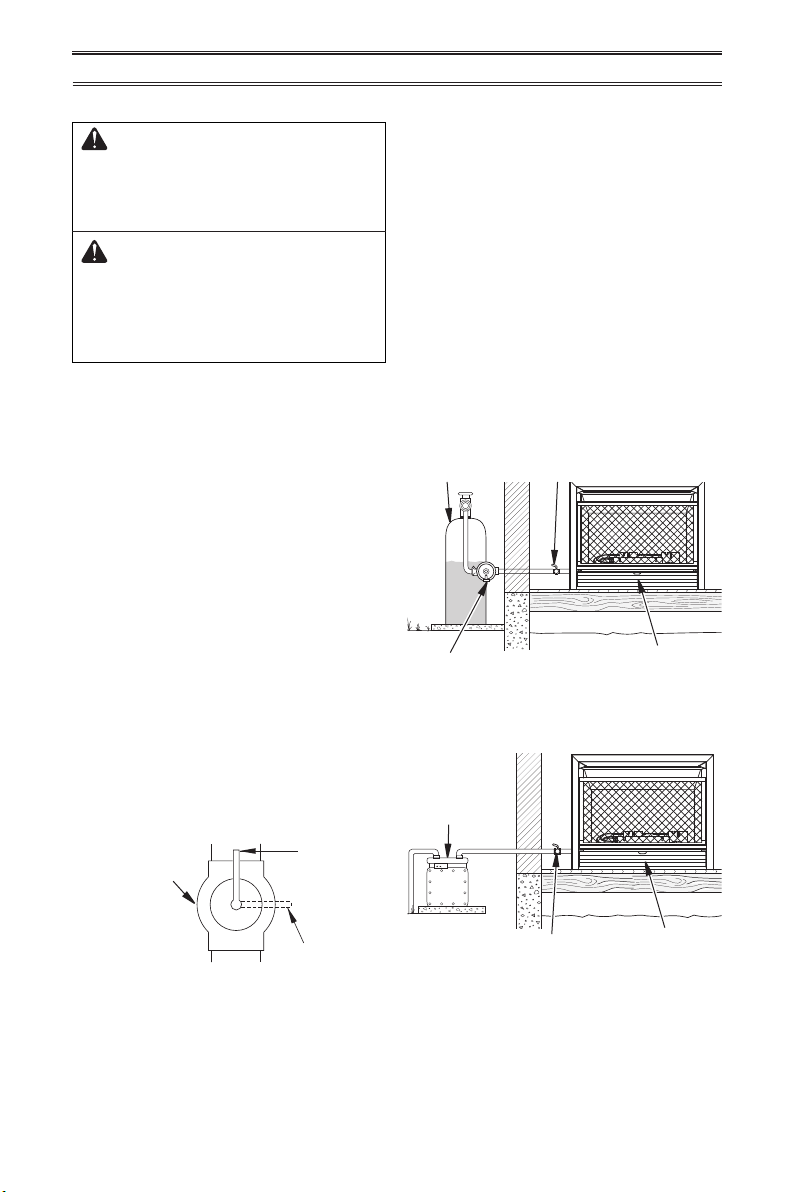
The installer must supply an external regula-
tor. The external regulator will reduce incom-
ing gas pressure. You must reduce incoming
gas pressure to between 11" and 14" of water.
If you do not reduce incoming gas pressure,
heater regulator damage could occur. Install
external regulator with the vent pointing down
as shown in Figure 13. Pointing the vent down
protects it from freezing rain or sleet.
Figure 13 - External Regulator
with Vent Pointing Down
Figure 14 - Gas Regulator Location and
Gas Line Access into Stove Cabinet
External
Regulator with
Vent Pointing
Down
Propane/LP
Supply Tank
Equipment
Shutoff Valve
Ground
Joint Union
3/8" NPT
Pipe Nipple
Tee Joint
Reducer
Bushing to
1/8" NPT
1/8" NPT
Plug Tap
Test Gauge
Connection*
Sediment
Trap
Tee Joint
Pipe Nipple
Gap
3" Minimum
Gas Regulator
Inlet Connector
Install sediment trap in supply line as shown
in Figure 12. Place sediment trap where it is
within reach for cleaning. Place sediment trap
where trapped matter is not likely to freeze.
A sediment trap traps moisture and contami-
nants. This keeps them from going into heater
controls. If sediment trap is not installed or is
installed wrong, heater may not run properly.
Natural Gas
From Gas Meter
(5" W.C.** to
9.5" W.C. Pressure)
Propane/LP
From External
Regulator
(11" W.C.**
to 14" W.C.
Pressure)
INSTALLATION
www.factorybuysdirect.com
200253-01D16
Figure 15 - Equipment Shutoff Valve
CHECKING GAS CONNECTIONS
Open
Closed
Equipment
Shutoff Valve
Control Valve
Location
Control Valve
Location
Equipment
Shutoff Valve
Equipment Shutoff Valve
External Regulator with
Vent Pointing Down
Propane/LP
Supply Tank
Figure 16 - Checking Gas Joints for
Propane/LP Gas
Figure 17 - Checking Gas Joints for
Natural Gas
Gas Meter
PRESSURE TESTING HEATER GAS CONNECTIONS
INSTALLATION
WARNING: Test all gas piping
and connections for leaks after
installing or servicing. Correct
all leaks at once.
WARNING: Never use an open
ame to check for a leak. Apply a
noncorrosive leak detection uid
to all joints. If bubbles form, there
is a leak. Correct all leaks at once.
PRESSURE TESTING GAS SUPPLY
PIPING SYSTEM
Test Pressures In Excess Of 1/2 PSIG (3.5 kPa)
1. Disconnect heater with its appliance main
gas valve (control valve) and equipment
shutoff valve from gas supply piping sys-
tem. Pressures in excess of 1/2 PSIG will
damage heater regulator.
2. Cap off open end of gas pipe where equip-
ment shutoff valve was connected.
3. Pressurize supply piping system by either
opening propane/LP supply tank valve
for propane/LP gas or opening main gas
valve located on or near gas meter for
natural gas or using compressed air.
4. Check all joints of gas supply piping sys-
tem. Apply noncorrosive leak detection
uid to all joints. If bubbles form, there
may be a leak.
5. Correct all leaks at once.
6. Reconnect heater and equipment shutoff
valve to gas supply. Check reconnected
ttings for leaks.
Test Pressures Equal To or Less Than
1/2 PSIG (3.5 kPa)
1. Close equipment shutoff valve (see Fig-
ure 15).
2. Pressurize supply piping system by either
opening propane/LP supply tank valve
for propane/LP gas or opening main gas
valve located on or near gas meter for
natural gas or using compressed air.
3. Check all joints from gas meter to equip-
ment shutoff valve for natural gas or
propane/LP supply to equipment shutoff
valve for propane/LP (see Figure 16 or 17).
Apply a noncorrosive leak detection uid
to all joints. Bubbles forming show a leak.
4. Correct all leaks at once.
1.
Open equipment shutoff valve (see Figure 15).
2. Open main gas valve located on or near
gas meter for natural gas or open pro-
pane/LP supply tank valve.
3. Make sure control knob of heater is in the
OFF position.
www.factorybuysdirect.com
17200253-01D
INSTALLING LOGS
INSTALLATION
4. Check all joints from equipment shutoff
valve to control valve (see Figure 16 or
17, page 16). Apply a noncorrosive leak
detection uid to all joints. Bubbles form-
ing show a leak.
5. Correct all leaks at once.
6. Light heater (see Lighting Instructions on
page 19). Check all other internal joints
for leaks.
7. Turn off heater (see To Turn Off Gas Ap-
pliance, page 20).
WARNING: Failure to posi-
tion the parts in accordance
with these diagrams or failure
to use only parts specically
approved with this heater may
result in property damage or
personal injury.
CAUTION: After installation,
and periodically thereafter,
check to ensure that no ame
comes in contact with any log.
With the heater set to high, check
to see if ames contact any log. If
so, reposition logs according to
the log installation instructions
in this manual. Flames contact-
ing logs will create soot.
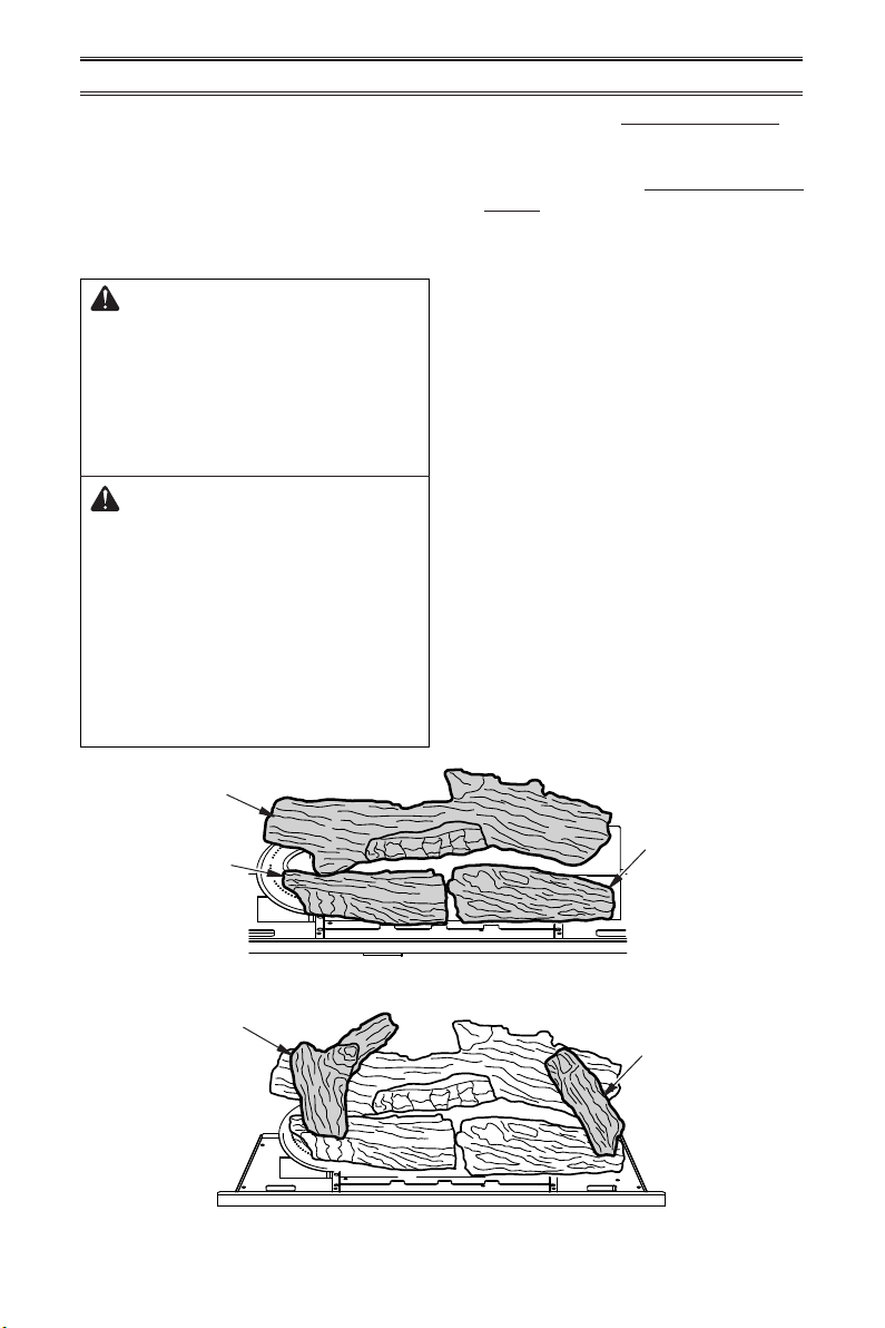
1. Install log 1 onto the two slots in the middle
plate (see Figure 18).
2. Install log 2 onto the two slots in the left
plate (see Figure 18).
3. Install log 3 onto the two slots in the right
plate (see Figure 18).
4. Install the recessed hole on the bottom of
log 4 onto the pin on log 1 and place onto
log 3 (see Figure 19).
5. Install the recessed hole on the bottom of
log 5 onto the pin on log 1 and place onto
log 2 (see Figure 19).
IMPORTANT: Make sure logs do not cover
any burner ports (see Figure 19). It is very
important to install the logs exactly as in-
structed. Do not modify logs. Use only logs
supplied with heater.
Log #1
Log #2
Log #3
Log #5
Log #4
Figure 18 - Installing Logs 1, 2 and 3
Figure 19 - Installing Logs 4 and 5
www.factorybuysdirect.com
200253-01D18
INSTALLATION
AA
AA
AA
AAA
AAA
AA
REMOTE
OFF
ON
LEARN
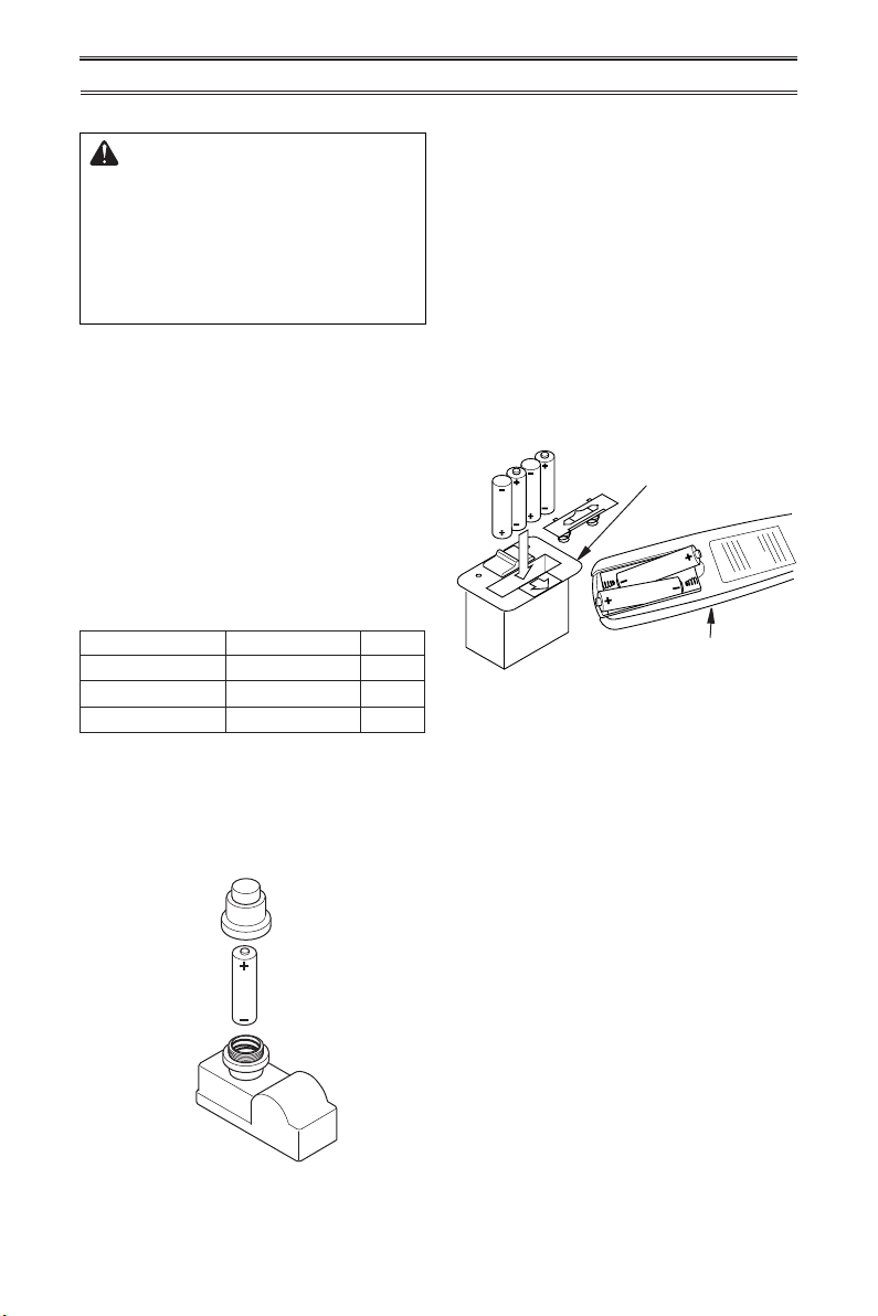
INSTALLING BATTERIES
CAUTION: Do not mix old and
new batteries. Do not mix alka-
line, standard (carbon - zinc), or
rechargeable (nickel - cadmium)
batteries. Do not dispose of
batteries in re, batteries may
explode or leak.
• Batteries are included.
• Remove batteries when depleted.
• Install/replace the batteries according to the
type and quantity stated in table below.
• Be sure to observe proper polarity (+/-)
when installing or replacing the batteries.
Damage due to improper battery installation
may void the warranty on the product.
• For remote control systems, maximize bat-
tery life by turning off the receiver when it
is not in use.
• For long periods of non-operation, remove
batteries from all components for safety.
Component Type of Battery Qty.
Ignitor AAA 1
Remote Control AAA 2 or 3*
Remote Receiver AA 4
*Note: Quantity depends on model of remote
Control.
Ignitor
Unscrew ignitor cap and install a AAA battery
with the + pointing out. Replace cap.
Figure 21 - Installing Batteries in Remote
Control and Receiver
Receiver
Remote Control
(Transmitter)
Receiver and Remote Control
Batteries are required in both the Remote
Control (Transmitter) (2 AAA size) and Re-
ceiver (4 AA size) (see Figure 21).
Note: Be sure batteries are placed correctly.
Reversing the batteries can cause damage to
the receiver and remote. Replace all batteries
on a yearly basis or sooner.
Position the slide switch on the front of the
receiver box in the ON position before install-
ing batteries. Once the batteries are installed
you will hear a single beep which indicates
the batteries are charged. If you do not hear
a beep, replace with new batteries.
Figure 20 - Installing Battery in Ignitor
AAA
Battery
Positive
UP
www.factorybuysdirect.com
19200253-01D
OPERATION
FOR YOUR SAFETY READ BEFORE LIGHTING
WARNING: If you do not fol-
low these instructions exactly, a
re or explosion may result caus-
ing property damage, personal
injury or loss of life.
A. This appliance has a pilot which must
be lighted by hand. When lighting the
pilot, follow these instructions exactly.
B. BEFORE LIGHTING smell all around
the appliance area for gas. Be sure to
smell next to the oor because some
gas is heavier than air and will settle
on the oor.
WHAT TO DO IF YOU SMELL GAS
• Do not try to light any appliance.
• Do not touch any electric switch; do
not use any phone in your building.
• Immediately call your gas supplier
from a neighbor’s phone. Follow the
gas supplier’s instructions.
• If you cannot reach your gas supplier,
call the re department.
C. Use only your hand to push in or turn
the gas control knob. Never use tools.
If the knob will not push in or turn
by hand, don’t try to repair it, call a
qualied service technician. Force or
attempted repair may result in a re or
explosion.
D. Do not use this appliance if any part
has been under water. Immediately call
a qualied service technician to inspect
the appliance and to replace any part of
the control system and any gas control
which has been under water.
WARNING: You must oper-
ate this heater with the screen
in place. Make sure screen is
installed before running heater.
NOTICE: During initial operation
of new heater, burning logs will
give off a paper-burning smell.
Orange ame will also be pres-
ent. Open damper or window to
vent smell. This will only last a
few hours.
1. STOP! Read the safety information above.
2. Make sure equipment shutoff valve is fully
open.
3. Turn control knob clockwise to the
OFF position.
4. Wait ve (5) minutes to clear out any gas.
Then smell for gas around heater and near
the oor. If you smell gas, STOP! Follow
"B" in the safety information above. If you
do not smell gas, go to the next step.
5. Turn control knob counterclockwise
to the PILOT position. Press in control
knob for ve (5) seconds (see Figure 22).
Note: The rst time that the heater is oper-
ated after connecting the gas supply,the
control knob should be pressed for about
thirty (30) seconds. This will allow air to
bleed from the gas system. If pilot does not
stay lit, refer to Troubleshooting, pages 28
though 31. Also contact a qualied service
technician or gas supplier for repairs. Until
repairs are made, light pilot with match.
• If control knob does not pop up when
released, contact a qualified service
technician or gas supplier for repairs.
LIGHTING INSTRUCTIONS
Figure 22 - Control Knob in the OFF
Position
Ignitor Button
Control Knob
www.factorybuysdirect.com
200253-01D20
OPERATION
Shutting Off Heater
Turn control knob clockwise to the
OFF position.
Shutting Off Burner Only (pilot
stays lit )
Turn control knob clockwise to the
PILOT position.
1. Remove screen by lifting and pulling
forward.
2. Follow steps 1 through 5 under Lighting
Instructions, page 19.
3. With control knob in PILOT position, strike
match, and hold near pilot. Press in control
knob; pilot should light.
4. Keep control knob pressed in for 30 sec-
onds after lighting pilot. After 30 seconds,
release control knob.
5. Make sure the heater screen is in place
before operating heater.
THERMOSTAT CONTROL OPERATION
The thermostatic control used on this model
differs from standard thermostats. Standard
thermostats simply turn the burner on and off.
The thermostat used on this heater senses the
room temperature. At times the room may ex-
ceed the set temperature. If so, the burner will
shut off. The burner will cycle back on when
room temperature drops below the set tem-
perature. The control knob can be set to any
comfort level between HIGH (5) and LOW (1).
Note: The thermostat sensing bulb measures
the temperature depending on housing con-
struction.
TO TURN OFF GAS TO APPLIANCE
MANUAL LIGHTING PROCEDURE
6. With control knob pressed in, push down
and release ignitor button. This will light
pilot. The pilot is attached to the rear
of the front of burner. If needed, keep
pressing ignitor button until pilot lights.
Note: If pilot does not stay lit, refer to
Troubleshooting, pages 28 though 31.
Also contact a qualied service technician
or gas supplier for repairs. Until repairs
are made, light pilot with match. To light
pilot with match, see Manual Lighting
Procedure.
7. Keep control knob pressed in for 30 sec-
onds after lighting pilot. After 30 seconds,
release control knob.
Note: If pilot goes out, repeat steps 3
through 7. This heater has a safety inter-
lock system. Wait one (1) minute before
lighting pilot again.
8. Be sure the slide switch on the front of the
receiver is in the ON position.
9. Turn control knob counterclockwise
to desired heating level. The main burner
should light. Set control knob to any heat
level between HI and LO (5 and 1).
10. Make sure the heater screen is in place
before operating heater.
11. If heater will not operate, follow the instruc-
tions To Turn Off Gas To Appliance, and
call your service technical or gas supplier.
CAUTION: Do not try to ad-
just heating levels by using the
equipment shutoff valve.
WARNING: If input gas
type is NG, make sure NG pilot
burner ignites. If input gas type
is LP, make sure LP pilot burner
ignites.
www.factorybuysdirect.com
21200253-01D
OPERATION
Key Settings
ON - Operates unit to on position, manually
operated solenoid ON.
OFF - Operates unit to off position, manually
operated solenoid OFF.
MODE - Changes unit from manual mode to
thermo mode.
SET - Sets temperature in thermo mode.
TEMP
ROOM SET TEMP
1
4
6
2
3
5
Figure 24 - Remote Control
Figure 25 - Remote Control Display
LCD Liquid Crystal Display
1. DISPLAY Indicates CURRENT room
temperature.
2. °F or °C Indicates degrees Fahrenheit or
Celsius.
3. FLAME Indicates burner/valve in operation.
4. ROOM Indicates remote is in THERMO
operation.
5. TEMP Appears during manual operation.
6. SET Appears during time the of setting
the desired temperature in the thermo
operation.
LEARN
REMOTE OFF
ON
Figure 23 - Receiver
Slide Switch
Learn Button
REMOTE CONTROL SYSTEM
Programming the Remote and Receiver
The remote and receiver must be “learned”
to one another.
To prepare the receiver box for learning, use
a pen or small screwdriver to gently press
and hold the learn button until you hear 3
series of beeps.
1. Place the slide switch on the receiver in
the remote position (see Figure 23).
2. Turn control knob on the heater to the ON
position.
3. Use a pen or small screwdriver to gently
press and hold the recessed LEARN
button on the face of the receiver for 2-3
seconds. You will hear a beep.
4. Press the ON button on the remote control
to light the burner (see Figure 24). You
will hear a series of beeps. This will also
"learn", or program, the remote and the
receiver.
Note: Remote must be at least 5 feet
away from the receiver during the learning
process.
Note: If the remote control is lost or dam-
aged, the slide switch on the receiver can
be used to operate the heater.
Note: When batteries are replaced the
learning process above must be repeated.
Remote Control Operation
This appliance must not be used with glass
doors in the closed position. This can lead
to pilot outages and severe sooting outside
the replace.
The transmitter operates on 2 AAA batteries.
www.factorybuysdirect.com
200253-01D22
OPERATION
2. Press and hold the SET key until the de-
sired set temperature is reached. The LCD
screen set numbers will increase from 45°
to 99° and then restart over at 45°.
3. Release the SET key. The LCD screen
will display the set temperature for 3 sec-
onds, then ash the set temperature for
3 seconds, then LCD screen will default
to display the room temperature.
To Change The Set Temperature
1. Press and hold the SET key until the
desired set temperature is reached. The
LCD screen set numbers will increase
from 45° to 99° then restart over at 45°.
2. Release the SET key. The LCD screen will
display the set temperature for 3 seconds,
then ash the set temperature for 3 sec-
onds, then the LCD screen will default to
display the room temperature.
3. Press the MODE key to disengage the
thermo mode. The word ROOM on the
LCD screen will not show when the thermo
is not in operation.
Note: The highest SET temperature is
99°F (32 °C) and the lowest temperature
is 45°F (6°C).
REMOTE CONTROL OPERATION
NOTES
The Thermo Feature on the transmitter op-
erates the appliance whenever the ROOM
TEMPERATURE varies a certain number of
degrees from the SET TEMPERATURE.
This variation is called the “swing” or tem-
perature differential. The normal operating
cycle of an appliance may be 4 times per
hour depending on how well the room or
home is insulated from the cold or drafts.
The factory setting for the “swing number” is
2. This represents a temperature variation of
+/-2°F (1°C) between SET temperature and
ROOM temperature, which determines when
the replace will be activated. The transmitter
has ON and OFF manual functions that are
activated by pressing either button on the
face of the transmitter. When a button on the
transmitter is pressed the word ON or OF will
appear on the LCD screen to show while the
signal is being sent. Upon initial use, there
may be a delay of three seconds before the
remote receiver will respond to the transmitter.
This is part of the system’s design.
Figure 26 - Manual Mode in ON Operation
Figure 27 - Manual Mode in OFF Operation
Setting°F/°C Scale
The factory setting for temperature is °F. To
change this setting to °C, press the ON key
and the OFF key on the remote control at the
same time (see Figure 24, page 21). This will
change from °F to °C. Follow this same pro-
cedure to change from °C back to °F.
Manual Function
To operate the system in the manual “MODE”
do the following.
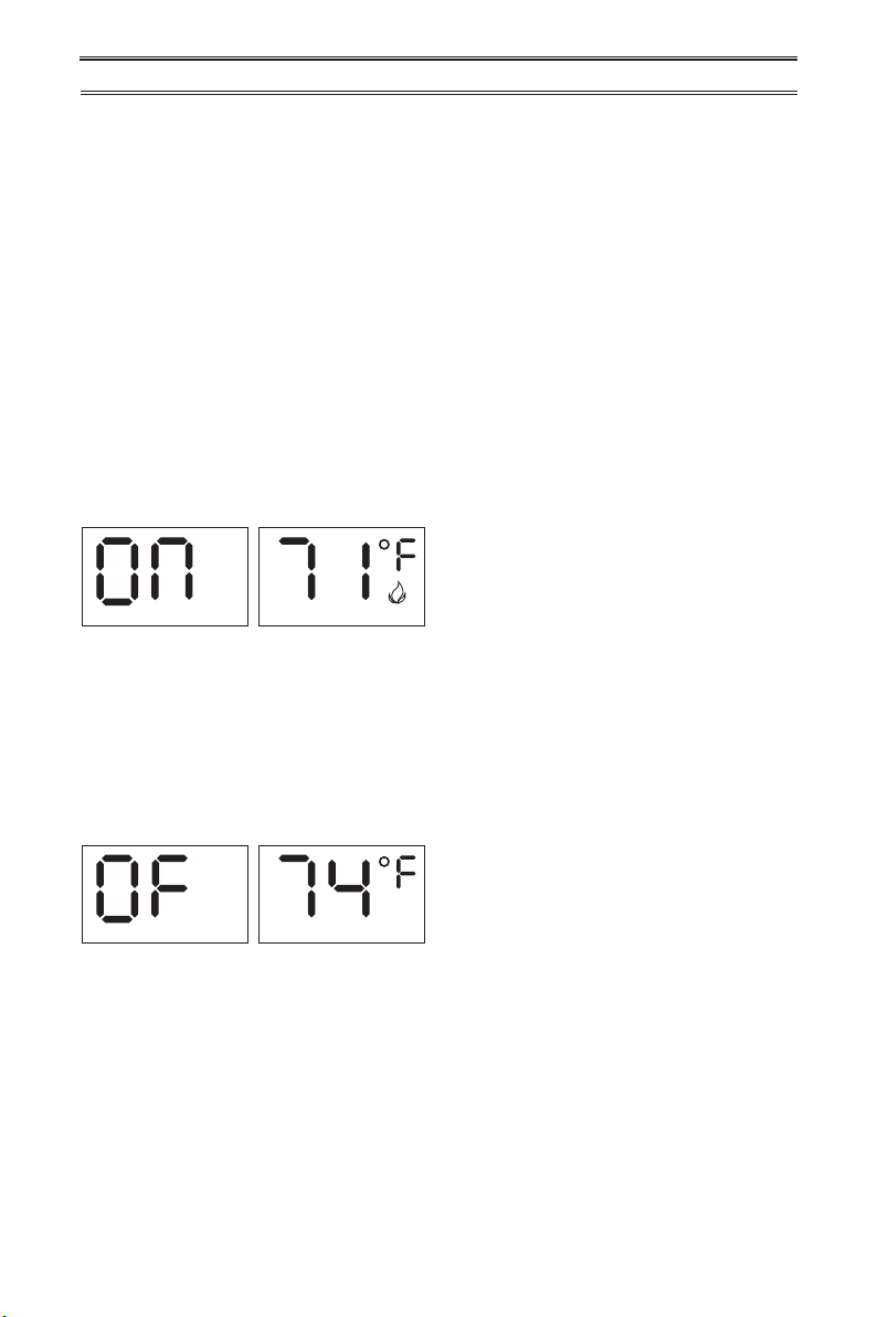
ON OPERATION
Press the ON key and the appliance ame will
come on. During this time the LCD screen will
show ON (see Figure 26).
After 3 seconds the LCD screen will default to
display room temperature and the word TEMP
will show (see Figure 26). The ame icon will
appear on LCD screen in manual on mode.
TEMP
TEMP
TEMP
TEMP
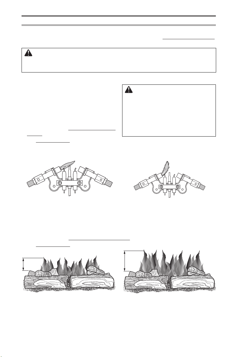
OFF OPERATION
Press the OFF key and the appliance ame
will shut off. During this time the LCD screen
will show OF (see Figure 27).
After 3 seconds the LCD screen will default to
display room temperature and the word TEMP
will show (see Figure 27).
THERMOSTAT FUNCTION
Setting Desired Room Temperature
The remote control system can control the
thermostat when the transmitter is in the
THERMO mode. The word ROOM must be
displayed on the screen.
To set the THERMO MODE and desired room
temperature:
1. Press the MODE key until the LCD screen
shows the word ROOM. The remote is
now in the thermostatic mode.
www.factorybuysdirect.com
23200253-01D
Approx. 3"-6" Above Top of Logs
More Than 8" Above Top of Logs
Approx. 3"-6" Above Top of Logs
More Than 8" Above Top of Logs
INSPECTING BURNERS
IMPORTANT: Owner’s should check pilot ame pattern and burner ame pattern often.
Incorrect ame patterns indicate the need for cleaning (see Care and Maintenance,
page 24) or service.
WARNING: Only a qualied service person should service and
repair heater. This includes maintenance requiring replacement or
alteration of components.
PILOT FLAME PATTERN
Figure 28 - Correct Pilot Flame Pattern
(Natural Gas shown)
Figure 29 - Incorrect Pilot Flame Pattern
(Natural Gas shown)
Figure 30 - Correct Burner Flame Pattern
with Control Knob Set to HI (5)
Figure 31 - Incorrect Burner Flame
Pattern with Control Knob Set to HI (5)
BURNER FLAME PATTERN
Figure 30 shows a correct burner ame pattern. Figure 31 shows an incorrect burner ame
pattern. If burner ame pattern is incorrect then:
• turn heater off (see To Turn Off Gas to Appliance, page 20).
• see Troubleshooting pages 28 through 31.
Figure 28 shows a correct pilot ame pattern.
Figure 29 shows an incorrect pilot ame pat-
tern. The incorrect pilot ame is not touching
the thermocouple. This will cause the ther-
mocouple to cool, which shuts the heater off.
If pilot ame pattern is incorrect, as shown
in Figure 29
• turn heater off (see To Turn Off Gas to Ap-
pliance, page 20)
• see Troubleshooting pages 28 through 31.
WARNING: If yellow tipping
occurs, your heater could pro-
duce increased levels of carbon
monoxide. If the burner ame
pattern shows yellow tipping,
follow instructions at bottom of
this page.
Notice: Do not mistake orange ames with
yellow tipping. Dirt or other ne particles enter
the heater and burn causing brief patches of
orange ame.
BURNER PRIMARY AIR HOLES
Air is drawn into the burner through the holes in the tting at the entrance to the burner. These
holes may become blocked with dust or lint. Periodically inspect these holes for any blockage
and clean as necessary. Blocked air holes will create soot.
NG
3-3.5" WC
Natural Gas
Shown
LP
8-11" WC
NG
3-3.5" WC
Natural Gas
Shown
LP
8-11" WC
www.factorybuysdirect.com
200253-01D24
Figure 32 - Burner and Injector Holder
CLEANING BURNER PILOT AIR INLET HOLE
We recommend that you clean the unit ev-
ery 2,500 hours of operation or every three
months. We also recommend that you keep
the burner tube and pilot assembly clean
and free of dust and dirt. To clean these
parts we recommend using compressed air
no greater than 30 PSl. Your local computer
store, hardware store, or home center may
carry compressed air in a can. You can use
a vacuum cleaner in the blow position. If us-
ing compressed air in a can, please follow
the directions on the can. If you don’t follow
directions on the can, you could damage the
pilot assembly.
1. Shut off the unit, including the pilot. Allow
the unit to cool for at least thirty minutes.
2. Inspect burner, pilot and primary air inlet
holes on injector for dust and dirt (see
Figure 32).
3. Blow air through the ports/slots and holes
in the burner. Also clean the pilot assembly.
4. Check the injector holder located at the
end of the burner tube again. Remove any
large particles of dust, dirt, lint, or pet hair
with a soft cloth or vacuum cleaner nozzle.
5. Blow air into the primary air holes on the
injector holder.
6. In case any large clumps of dust have now
been pushed into the burner. Repeat steps
3 and 4.
Injector
Burner
Tube
Primary Air Inlet Holes
CARE AND MAINTENANCE
WARNING: Turn off heater and let cool before servicing.
CAUTION: You must keep control areas, burner, and circulating
air passageways of heater clean. Inspect these areas of heater before
each use. Have heater inspected yearly by a qualied service techni-
cian. Heater may need more frequent cleaning due to excessive lint
from carpeting, bedding material, pet hair, etc.
WARNING: Failure to keep the primary air opening(s) of the
burner(s) clean may result in sooting and property damage.
MAIN BURNER
Periodically inspect all burner ame holes with
the heater running. All slotted burner ame
holes should be open with yellow ame pres-
ent. All round burner ame holes should be
open with a small blue ame present. Some
burner ame holes may become blocked by
debris or rust, with no ame present. If so,
turn off the heater and let it cool, and remove
blockage or replace burner. Blocked burner
ame holes will create soot.
www.factorybuysdirect.com
25200253-01D
Use a vacuum cleaner, pressurized air, or a
small, soft bristled brush to clean.
A yellow tip on the pilot ame indicates dust
and dirt in the pilot assembly. There is a small
pilot air inlet hole about 2" from where the
pilot ame comes out of the pilot assembly
(see Figure 33). With the unit off, lightly blow
air through the air inlet hole. You may blow
through a drinking straw if compressed air is
not available.
Figure 33 - Pilot Inlet Air Hole
CARE AND MAINTENANCE
CABINET
ODS/PILOT
Air Passageways
Use a vacuum cleaner or pressurized air to
clean.
Exterior
• Use a soft cloth dampened with a mild soap
and water mixture.
• Wipe the cabinet to remove dust.
LOGS
• If you remove logs for cleaning, refer to Installing Logs, page 17, to properly replace logs.
• Replace log(s) if broken or chipped (dime-size or larger).
BLOWER (OPTIONAL ACCESSORY)
Refer to blower manual.
(Back of pilot
shown for clarity)
Pilot Air
Inlet Hole
Natural Gas
Burner
Propane/LP
Gas Burner
Thermocouple
Pilot Air Inlet Hole
Ignitor
Electrode
www.factorybuysdirect.com
200253-01D26
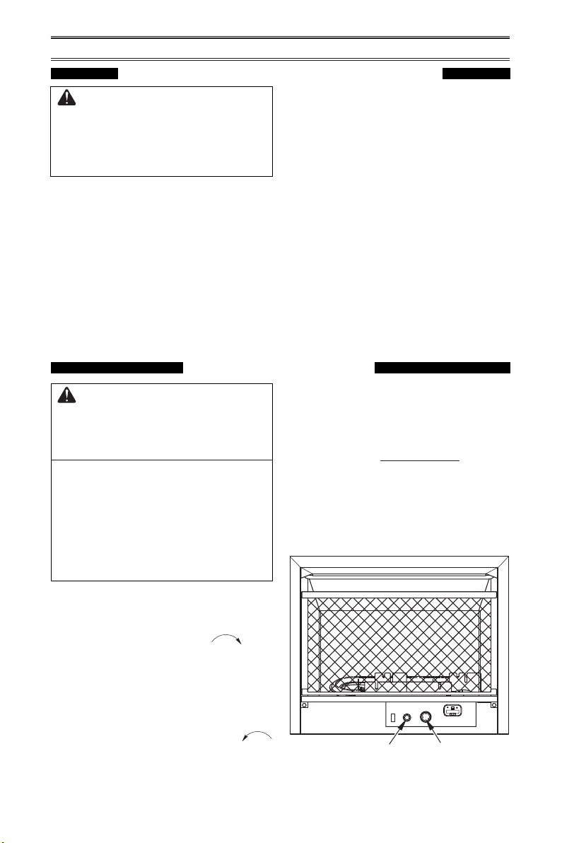
ELECTRICAL
ELECTRICAL CONNECTION
FOR STOVES EQUIPPED WITH A BLOWER
Do not use this stove if any
part of it has been under water.
Immediately call a qualied ser-
vice technician to inspect the
stove and replace any part of
the electrical system which has
been under water.
GROUNDING INSTRUCTIONS
This stove is for use on 120 volts. The cord
has a plug as shown at A in Figure 34. An
adapter as shown at C is available for con-
necting three-blade grounding-type plugs to
two-slot receptacles. The green grounding
lug extending from the adapter must be
connected to a permanent ground such as
Grounding Pin
Grounding Means
Metal Screw
Cover of
Grounded
Outlet Box
A
B
C
Adapter
Figure 34 - Grounded Electrical Outlet
ELECTRICAL WIRING
Any electrical re-wiring of this stove must be
done by a qualied electrician. This wiring
must be done in accordance with local codes
and/or in Canada with the current CSA C22.1
Canadian Electrical Code, and for US instal-
lations, the National Electrical Code ANSI/
NFPA NO 70.
WARNING: If repairing or
replacing any electrical compo-
nent or wiring, the original wire
routing, color coding and secur-
ing locations must be followed.
a properly grounded outlet box. The adapter
should not be used if a three-slot grounded
receptacle is available.
(Sold
Separately)
CAUTION: Label all wires
prior to disconnection when
servicing controls. Wiring errors
can cause improper and danger-
ous operation.
www.factorybuysdirect.com
27200253-01D
Gas Inlet / Gas esté
INLET GAS PRESSURE MAX 1/2 PSIG (3.5 KPa)
200110-01B
03/15
WARNING: Make sure Regulator Cap is in the appropriate position
as shown in diagrams. Installation and service should be done by
qualified service technician only.
Natural Gas
When using natural gas:
Make sure the cap is installed in the propane/LP inlet of regulator.
Use thread sealant to assure there are no leaks.
Propane/LP Gas
When using propane/LP gas:
Make sure the cap is installed in the natural gas (NG) inlet of regulator.
Use thread sealant to assure there are no leaks.
ADVERTENCIA: Asegúrese la tapa del regulador esté en la posición adecuada,
como se muestra en los diagramas. La instalación y reparaciones deben ser realizadas
por un técnico de servicio calificado solamente.
Gas Natural
Cuando se utiliza gas natural:
Asegúrese de que la tapa está instalado en el propano/LP entrada del regulador.
Utilice sellador de roscas para asegurar que no haya fugas.
Propano/LP Gas
Cuando se utiliza el gas propano / LP:
Asegúrese de que la tapa está instalado en la entrada de gas natural (GN) del regulador.
Utilice sellador de roscas para asegurar que no haya fugas.
Correct Pilot Flame Pattern
Incorrect Pilot Flame Pattern
NG
3-3.5" WC
Natural Gas
Shown
LP
8-11" WC
NG
3-3.5" WC
Natural Gas
Shown
LP
8-11" WC
1/2 Glas
s
Height
1/2 Glas
s
Height
Yellow
Tipping
Correct Burner Flame Pattern
Incorrect Burner Flame Pattern
LP
Blue Plunger
INSTALL SUPPLIED CAP IN FITTING
NOT BEING USED.
INSTALAR TAPA SUMINISTRADA MONTAJE NO SE UTILIZA.
NG
Yellow Plunger
This appliance may be installed in an aftermarket,*
permanently located, manufactured (mobile) home, where
not prohibited by local codes.
This appliance is only for use with propane or natural gas.
Field conversion by any other means including the use of
a kit is not permitted.
WARNING: Make sure the supplied cap is
installed in unused regulator fitting before
connecting the correct gas supply line.
WARNING: Do not use natural gas and
propane gas together.
CAUTION: Two gas line installations at
the same time are prohibited.
ADVERTENCIA: Asegúrese de que la línea
no utilizado se conecta por primera vez
antes de conectar la línea de suministro
de gas correcta.
ADVERTENCIA: No utilice el gas natural y
el gas propano juntos.
PRECAUCIÓN: Dos instalaciones de
líneas de gas al mismo tiempo están
prohibidos.
FOR PROPANE GAS SUPPLY
PARA LA FUENTE DE GAS DEL PROPANE
CAUTION: The heater requires an external regulator to reduce
the LP tank pressure to a maximum of 14" W.C. Never connect
this product directly to the supply tank.
PRECAUCIÓN: El calentador requieres una externa regulador
para reducir la presión del tanque de gas a un máximo de 14"
W.C. Nunca conecte este producto directamente al tanque de
suministro.
FOR NATURAL GAS SUPPLY
PARA LA FUENTE DE GAS DEL NATURAL
NOTICE: An additional gas regulator will be necessary if the
local natural gas pressure exceeds the heater's rated maximum
inlet pressure. If in doubt, contact the local gas utility. If natural
gas inlet pressure exceeds 10" W.C., the safety pressure switch
will activate. See owners manual for proper procedure to bypass
the pressure switch.
AVISO: Un regulador de gas adicional será necesario si la
presión del gas natural local excede de entrada nominal máxima
del calentador presión. En caso de duda, póngase en contacto
con la compañía de gas local. Si la presión de entrada de gas
natural supera los 10" WC, el interruptor de presión de
seguridad se activará. Consulte el manual del propietario para el
procedimiento adecuado de derivación el interruptor de presión.
Procom Heating, Inc. U.S. Patent Information
This product may be covered by one or more of the following
United States patents:
8,915,239 8,851,065 8,764,436 8,757,202 8,757,139 8,752,541
8,568,136 8,545,216 8,517,718 8,516,878 8,506,290 8,465,277
8,317,511 8,297,968 8,281,781 8,241,034 8,235,708 8,152,515
8,011,920 7,967,006 7,967,007 7,654,820 7,730,765 7,677,236
7,607,426 7,434,447
Other patents pending.
TOLL-FREE Customer Care Number: 1-866-573-0674
Numero de Atención al Cliente GRATUITO: 1-866-573-0674
Visit our website for more information www.usaprocom.com
Visite nuestra página web para más informacion www.usaprocom.com
WARNING: Never attempt to
service stove while it is plugged
in, operating, or hot. Burns and
electrical shock could result.
Only a qualied service person
should service or repair stove.
ELECTRICAL
DC 6V 1.5A
Adaptor
120V 60Hz
Power
Change
Assembly
Reciever
(4 AA Batteries Required)
Valve
Red
Red
Yellow
Black
Black
Red
Black
Pin and Socket Connector
LEARN
REMOTE OFF
ON
Power Change
Assembly
Power Change
Assembly
Verify proper operation after servicing. If any
of the original wire as supplied with the stove
must be replaced, it must be replaced with a
wire of at least a 105º C temperature rating.
www.factorybuysdirect.com
200253-01D28
TROUBLESHOOTING
WARNING: If you smell gas:
• Shut off gas supply.
• Do not try to light any appliance.
• Do not touch any electrical switch; do not use any phone in your
building.
• Immediately call your gas supplier from a neighbor’s phone. Fol-
low the gas supplier’s instructions.
• If you cannot reach your gas supplier, call the re department.
WARNING: Only a qualied service technician should service and
repair heater. Make sure that power is turned off before proceeding.
Turn off and let cool before servicing.
CAUTION: Never use a wire, needle, or similar object to clean
ODS/pilot. This can damage ODS/ pilot unit.
IMPORTANT: Operating heater where impurities in air exist may create odors. Cleaning sup-
plies, paint, paint remover, cigarette smoke, cements and glues, new carpet or textiles, etc.,
create fumes. These fumes may mix with combustion air and create odors.
Note: All troubleshooting items are listed in order of operation.
NG
Figure 35 - Gas Regulator Pressure Switch
Pressure
Switch
Set Screw
Pressure Switch
When using natural gas (NG), there is a pres-
sure switch that acts to turn off the gas ow to
the pilot if the inlet pressure exceeds 9.5" WC.
This is to prevent the operation of the unit on
the wrong gas (propane/LP). If your natural
gas supply exceeds 9.5" WC the unit will
not operate. Either contact your gas supplier
to check and adjust the inlet pressure or a
qualied service technician can bypass the
pressure switch.
Before attempting to bypass the pressure
switch, make sure the type of gas being used
is correct. Check to make sure the connection
tting is in the correct inlet on the regulator.
Refer to Connecting to Gas Supply, page 14.
Only a qualied installer should bypass the
pressure switch. To bypass the pressure
switch locate the set screw on the regulator.
Use a small at bladed screw driver to turn the
set screw counterclockwise 2 turns. This will
bypass the pressure switch function.
Problem Possible Cause Corrective Action
Using natural gas and
pilot will not light.
Inlet pressure exceeds
9.5" WC.
Bypass pressure switch. See
instructions below.
The entire gas delivery piping including con-
nections inside the heater should be leak
tested by the qualied installer. After leak
testing the qualied installer should light the
appliance. Refer to the correct ame pattern
as illustrated on page 23. All ame patterns
should be safely inside the product. If for any
reason they are not, stop use of the appliance
and call for repairs.

www.factorybuysdirect.com
29200253-01D
Problem Possible Cause Corrective Action
When ignitor button is
pressed in, there is no
spark at ODS/pilot
1. Ignitor electrode is posi-
tioned wrong. Ignitor elec-
trode is broken.
2. Ignitor electrode is not con-
nected to ignitor cable.
3. Ignitor cable is pinched or
wet.
4 Broken ignitor cable.
5. Bad piezo ignitor.
6. Low battery.
1. Replace electrode.
2. Replace ignitor cable
3. Free ignitor cable if pinched
by any metal or tubing. Keep
ignitor cable dry.
4. Replace ignitor cable.
5. Replace piezo ignitor.
6. Replace battery.
When ignitor button is
pressed in there is a
spark at ODS/pilot but no
pilot ame present.
1. Gas supply is turned off or
equipment shutoff valve is
closed.
2. Control knob not fully
pressed in while pressing
ignitor button.
3. Air in gas lines (new instal-
lation or recent gas interrup-
tion).
4. ODS / pilot is clogged.
5. Incorrect inlet gas pressure
or inlet regulator is damaged.
6. Control knob not in PILOT
position.
7. Depleted gas supply (pro-
pane).
1. Turn on gas supply or open
equipment shutoff valve.
2. Fully press in control knob
while pressing ignitor button.
3. Continue holding down con-
trol knob. Repeat igniting op-
eration until air is removed.
4.
Clean ODS/pilot (see Care
and Maintenance, page 24) or
replace ODS/pilot assembly.
5. Check inlet gas pressure or
replace inlet gas regulator.
6. Turn control knob to PILOT
position.
7. Contact local propane/LP
gas company.
ODS/pilot lights but ame
goes out when control
knob is released.
1. Control knob is not fully
pressed in.
2. Control knob is not pressed
in long enough.
3. Equipment shutoff valve is
not fully open.
4. Thermocouple connection is
loose at control valve.
5. Pilot flame not touching
thermocouple, which allows
thermocouple to cool, caus-
ing pilot ame to go out. This
problem could be caused by
one or both of the following:
A) Low gas pressure
B) Dirty or partially clogged
ODS/pilot
6. Thermocouple damaged.
7. Control valve damaged.
1. Press in control knob fully.
2. After ODS/pilot lights, keep
control knob pressed in 30
seconds.
3. Fully open equipment shutoff
valve.
4. Hand tighten until snug, and
then tighten 1/4 turn more.
5. A) Contact local natural or
propane/LP gas company
B) Clean ODS/pilot (see
Care and Maintenance,
page 24) or replace ODS/
pilot assembly
6. Replace thermocouple.
7. Contact customer service.
TROUBLESHOOTING

www.factorybuysdirect.com
200253-01D30
Problem Possible Cause Corrective Action
Burner(s) does not light
after ODS/pilot is lit
1. Burner orice is clogged.
2. Burner orice diameter is too
small.
3. Inlet gas pressure is too low.
1. Clean burner orifice (see
Care and Maintenance,
page 24) or replace burner
orice.
2. Replace burner orice.
3. Contact local gas supplier.
Delayed ignition of
burner(s).
1. Manifold pressure is too low.
2. Burner orice is clogged.
1. Contact local gas supplier.
2. Clean burner (see Care and
Maintenance, page 24) or
replace burner orice.
Burner backring during
combustion
1. Burner orice is clogged or
damaged.
2. Burner is damaged.
3. Gas regulator is damaged.
1. Clean burner orifice (see
Care and Maintenance,
page 24) or replace burner
orice.
2. Contact dealer or customer
service.
3. Replace gas regulator.
High yellow ame during
burner combustion
1. Not enough air.
2. Gas regulator is defective.
3. Inlet gas pressure is too low.
1. Check burner for dirt and
debris. If found, clean burner
(see Care and Maintenance,
page 24).
2. Replace gas regulator.
3. Contact local gas supplier.
Gas odor during com-
bustion.
1. Foreign matter between
control valve and burner.
2. Gas leak. (See Warning
Statement at top of page 26).
1. Take apart gas tubing and
remove foreign matter.
2. Locate and correct all leaks
(see Checking Gas Connec-
tions, page 16).
Slight smoke or odor dur-
ing initial operation
1. Residues from manufactur-
ing process.
1. Problem will stop after a few
hours of operation.
Heater produces a whis-
tling noise when burner
is lit..0
1. Turning control knob to high
(5) position when burner is
cold.
2. Air in gas line.
3. Air passageways on heater
are blocked.
4. Dirty or partially clogged
burner orice.
1. Turn control knob to low (1)
position and let warm up for
a minute.
2. Operate burner until air is
removed from line. Have gas
line checked by local gas
supplier.
3 Observe minimum installa-
tion clearances (Figure 5,
page 9)
4 Clean burner (see Care and
Maintenance, page 24) or
replace burner orice.
TROUBLESHOOTING

www.factorybuysdirect.com
31200253-01D
TROUBLESHOOTING
Problem Possible Cause Corrective Action
Heater produces a click-
ing/ticking noise just after
burner is lit or shut off.
1. Metal is expanding while
heating or contracting while
cooling.
1. This is common with most
heaters. If noise is exces-
sive, contact qualied ser-
vice technician.
White powder residue
forming within burner
box or on adjacent walls
or furniture
1. When heated, the vapors
from furniture polish, wax,
carpet cleaners, etc., turn
into white powder residue.
1. Turn heater off when using
furniture polish, wax, carpet
cleaner or similar products.
Heater produces un-
wanted odors.
1. Heater is burning vapors from
paint, hair spray, glues, etc.
See IMPORTANT statement,
page 26.
2. Gas leak. See Warning State-
ment at the top of page 26.
3 Low fuel supply.
1. Ventilate room. Stop using
odor causing products while
heater is running.
2. Locate and correct all leaks
(see Checking Gas Connec-
tions, page 16).
3. Rell supply tank (Propane/
LP models).
Heater shuts off in use
(ODS operates).
1. Not enough fresh air is avail-
able.
2. Low line pressure.
3. ODS/pilot is partially
clogged.
1. Open window and/or door for
ventilation.
2. Contact local gas supplier.
3. Clean ODS/pilot (see Care
and Maintenance, page 24).
Gas odor exists even
when control knob is in
OFF position.
1. Gas leak. See Warning
Statement at top of page 26.
2. Control valve is defective.
1. Locate and correct all leaks
(see Checking Gas Connec-
tions, page 16).
2. Contact customer service.
Moisture/condensation
noticed on windows.
1. Not enough combustion/
ventilation air.
1. Refer to Air for Combus-
tion and Ventilation require-
ments, page 6 .
SERVICE HINTS
When Gas Pressure Is Too Low
• pilot will not stay lit
• burners will have delayed ignition
• replace will not produce specied heat
• propane/LP gas supply might be low (propane/LP units only)
You may feel your gas pressure is too low. If so, contact your local gas supplier.
TECHNICAL SERVICE
You may have further questions about installation, operation, or troubleshooting. If so, contact
Factory Buys Direct at 1-855-607-6557.
When calling, please have your model and serial numbers of your heater ready.
www.factorybuysdirect.com
200253-01D32
PARTS
MODEL FDF300R
REMOTE
OFF
ON
LEARN
2
1
5
7
13
14
3
15
16
4
17
6
8
9
10
12
11

www.factorybuysdirect.com
33200253-01D
PARTS
MODEL FDF300R
This list contains replaceable parts for your heater. When ordering replacement parts, follow
the instructions listed under Replacement Parts, page 34 of this manual.
ITEM PART # DESCRIPTION QTY
1 MRT-01 Remote Control Valve 1
2 RVD88-Y-4/9 Regulator 1
3 ** Burner Assembly 1
4 ND0310A-400-PU2 ODS 1
5 PIMDNI-01 Piezo Ignitor 1
6 QX18W060150FU 6V DC Adapter 1
7 FB28D04-B Hood 1
FB28D500-D Log Set 1
8 FB28D501-D Log 1 1
9 BL037-02-B Log 2 1
10 BL038-02-B Log 3 1
11 BL041-02 Log 4 1
12 FB28D505-C Log 5 1
13 FB28D07-B Screen 1
14 F300R100B-01 Lower Front Access Door 1
15 RG04-2M Receiver 1
16 RG04-1T Remote Control 1
17 RG04-1M-PA Power Change Assembly 1
PART AVAILABLE - NOT SHOWN
PCAM-012 AAA Battery 1
160960-01 Inlet Cover Assembly 1
160960-04 Valve Fitting Assembly 1
** Not a eld replaceable part.

www.factorybuysdirect.com
200253-01D34
REPLACEMENT PARTS
Note: Use only original replacement parts. This will protect your warranty coverage for parts
replaced under warranty.
PARTS UNDER WARRANTY
Contact authorized dealers of this product.
If they can’t supply original replacement
parts, call Customer Service toll free at
1-855-607-6557 for referral information.
When calling Customer Service or your dealer,
have ready:
• Your name
• Your address
• Model and serial number of your heater
• How heater was malfunctioning
• Type of gas supply and Propane/LP tank size
• Purchase date
Usually, we will ask you to return the defective
part to the factory
PARTS NOT UNDER WARRANTY
Contact authorized dealers of this product.
If they can’t supply original replacement
part(s) call Customer Service toll free at
1-855-607-6557 for referral information.
When calling Customer Service have ready:
• Model number of your heater
• The replacement part number
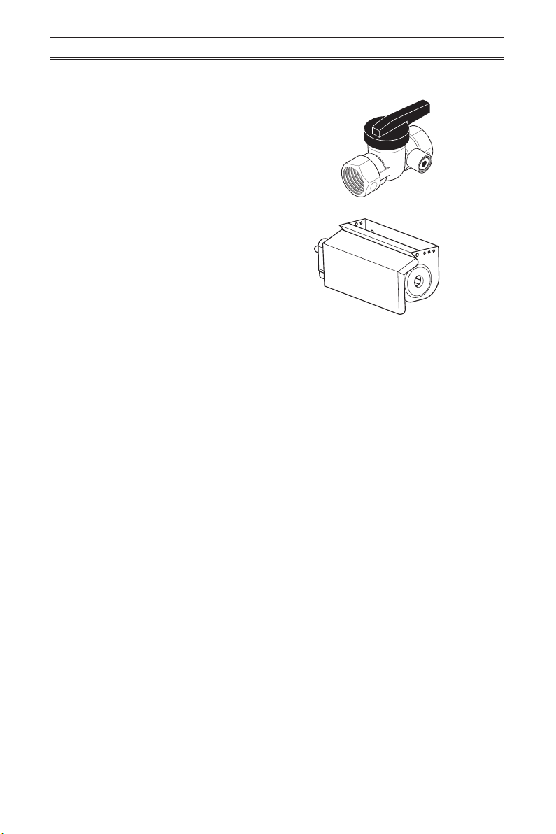
www.factorybuysdirect.com
35200253-01D
ACCESSORIES
Purchase these heater accessories from your local dealer. If they can not supply these acces-
sories, contact Factory Buys Direct at 1-855-607-6557 for information.
EQUIPMENT SHUTOFF VALVE
For all models. Equipment shutoff valve with
1/8" NPT tap.
OPTIONAL FAN KIT
Optional fan kit part FIB100. The fan has 3
settings ON/OFF/Auto.

200253-01
Rev. D
06/16
WARRANTY
KEEP THIS WARRANTY
Model _______________________________
Serial No. ____________________________
Date Purchased _______________________
Keep receipt for warranty verication.
REGISTER YOUR PRODUCT AT WWW.FACTORYBUYSDIRECT.COM
FACTORY BUYS DIRECT LIMITED WARRANTIES
New Products
Standard Warranty: Factory Buys Direct warrants this new product and any parts thereof to be free from
defects in material and workmanship for a period of one (1) year from the date of rst purchase from an
authorized dealer provided the product has been installed, maintained and operated in accordance with
Factory Buys Direct’s warnings and instructions.
For products purchased for commercial, industrial or rental usage, this warranty is limited to 90 days from
the date of rst purchase.
Factory Reconditioned Products
Limited Warranty: Factory Buys Direct warrants factory reconditioned products and any parts thereof to be
free from defects in material and workmanship for a period 30 days from the date of rst purchase from an
authorized dealer provided the product has been installed, maintained and operated in accordance with Factory
Buys Direct’s warnings and instructions. No return will be authorized. Parts will be provided to repair the product.
Terms Common to All Warranties
The following terms apply to all of the above warranties:
Always specify model number and serial number when contacting the manufacturer. To make a claim under
this warranty, the bill of sale or other proof of purchase must be presented.
This warranty is extended only to the original retail purchaser when purchased from an authorized dealer,
and only when installed by a qualied installer in accordance with all local codes and instructions furnished
with this product.
This warranty covers the cost of part(s) required to restore this product to proper operating condition and
an allowance for labor when provided by a Factory Buys Direct Authorized Service Center or a provider ap-
proved by Factory Buys Direct. Warranty parts must be obtained through authorized dealers of this product
and/or Factory Buys Direct who will provide original factory replacement parts. Failure to use original factory
replacement parts will void this warranty.
Traveling, handling, transportation, diagnostic, material, labor and incidental costs associated with warranty
repairs, unless expressly covered by this warranty, are not reimbursable under this warranty and are the
responsibility of the owner.
Excluded from this warranty are products or parts that fail or become damaged due to misuse, accidents,
improper installation, lack of proper maintenance, tampering or alteration(s).
This is Factory Buys Direct’s exclusive warranty, and to the full extent allowed by law; this express warranty
excludes any and all other warranties, express or implied, written or verbal and limits the duration of any
and all implied warranties, including warranties of merchantability and tness for a particular purpose to one
(1) year on new products and 30 days on factory reconditioned products from the date of rst purchase.
Factory Buys Direct makes no other warranties regarding this product.
Factory Buys Direct’s liability is limited to the purchase price of the product and Factory Buys Direct shall not
be liable for any other damages whatsoever under any circumstances including direct, indirect, incidental,
or consequential damages.
Some states do not allow limitations on how long an implied warranty lasts or the exclusion or limitation of
incidental or consequential damages, so the above limitation or exclusion may not apply to you.
This warranty gives you specic legal rights, and you may also have other rights which vary from state to state.
Factory Buys Direct
500 Brown Industrial Parkway
Canton, GA 30114
1-855-607-6557