Loading ...
Loading ...
Loading ...
If used in mobile homes or if local codes DO
NOT permit connection of the frame grounding
conductor to the neutral (white) wire, separate
the white and bare copper ground wires that extend
out of the end of the supply cable of the appliance.
Connect the white wire from supply cable to the
neutral white wire in the junction box. Connect the
black and red wires from the supply cable to the
matching color wires in the junction box. The bare
wire must now be used to ground the appliance in
accordance with local electrical codes. Connect the
bare copper ground wire to the grounded lead in the
service panel. DO NOT ground to a gas supply pipe.
DO NOT connect to electrical power supply until
appliance is permanently grounded. Connect the
ground wire before turning on the power
(see Figure 5).
Cable from Power Supply
Ground Wire
_White Wire
Red_l\. _
_ Black
Ground Wire _t_--_ _ W,res
(Bare or Green Wire)_/_
/
rid,,,,,,,,_
White Wire
Junction Box _ _ U.L.-Listed Conduit
Connector (or CSA listed)
Cable from appliance
Figure 5
4-WIRE GROUNDED JUNCTION BOX
If connecting to a 4-wire electrical
system (mobile homes), the appliance frame MUST
NOT be connected to the neutral wire of the 4-wire
electrical system.
NOTE TO ELECTRICIAN: The armored cable leads
supplied with the appliance are CSA-recognized for
connection to larger gauge household wiring. The
insulation of the leads is rated at temperatures much
higher than temperature rating of household wiring. The
current carrying capacity of the conductor is governed by
the temperature rating of the insulation around the wire,
rather than the wire gauge alone.
Do not lift the oven by the door
handle.
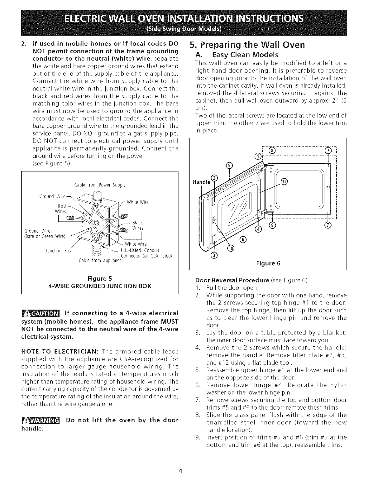
5. Preparing the Wall Oven
A. Easy dean Models
This wall oven can easily be modified to a left or a
right hand door opening. It is preferable to reverse
door opening prior to the installation of the wall oven
into the cabinet cavity. If wall oven is already installed,
removed the 4 lateral screws securing it against the
cabinet, then pull wall oven outward by approx. 2" (5
cm).
Two of the lateral screws are located at the low end of
upper trim; the other 2 are used to hold the lower trim
in place.
0D
Figure 6
Door Reversal Procedure (see Figure 6)
1. Pull the door open.
2. While supporting the door with one hand, remove
the 2 screws securing top hinge #1 to the door.
Remove the top hinge, then lift up the door such
as to clear the lower hinge pin and remove the
door.
3. Lay the door on a table protected by a blanket;
the inner door surface must face toward you.
4. Remove the 2 screws which secure the handle;
remove the handle. Remove filler plate #2, #3,
and #12 using a flat blade tool.
5. Reassemble upper hinge #I at the lower end and
on the opposite side of the door.
6. Remove lower hinge #4. Relocate the nylon
washer on the lower hinge pin.
7. Remove screws securing the top and bottom door
trims #5 and #6 to the door; remove these trims.
8. Slide the glass panel flush with the edge of the
enamelled steel inner door (toward the new
handle location).
9. Invert position of trims #5 and #6 (trim #5 at the
bottom and trim #6 at the top); reassemble trims.
Loading ...
Loading ...
Loading ...