Loading ...
Loading ...
Loading ...
English
4
The label on your tool may include the following symbols. The
symbols and their definitions are asfollows:
V ......................... volts
Hz .......................hertz
min ..................... minutes
or DC ......direct current
...................... Class I Construction
(grounded)
…/min ..............per minute
BPM .................... beats per minute
IPM ..................... impacts per minute
RPM .................... revolutions per
minute
sfpm ................... surface feet per
minute
SPM .................... strokes per minute
OPM .................... oscillations per
minute
A ......................... amperes
W ........................watts
or AC ...........alternating current
or AC/DC .... alternating or
direct current
...................... Class II
Construction
(double insulated)
n
o
.......................no load speed
n .........................rated speed
......................earthing terminal
.....................safety alert symbol
.....................visible radiation
..................... avoid staring at
light
..................... wear respiratory
protection
..................... wear eye
protection
..................... wear hearing
protection
..................... read all
documentation
IPXX .................... IP symbol
ASSEMBLY AND ADJUSTMENTS
WARNING: To reduce the risk of
serious personal injury, turn unit off and
disconnect it from power source before making
any adjustments or removing/installing
attachments or accessories. An accidental start-up
can causeinjury.
Motor
Be sure your power supply agrees with the nameplate
marking. Voltage decrease of more than 10% will cause loss
of power and overheating. These tools are factory tested; if
this tool does not operate, check power supply.
Intended Use
This appliance is designed for residential outdoor
trimmingapplications.
DO nOT use under wet conditions or in presence of
flammable liquids orgases.
DO nOT let children come into contact with the tool.
Supervision is required when inexperienced operators use
thistool.
WARNING: Unplug the trimmer before
attempting to attach the guard, EDGE GUIDE OR
HANDLE. NEVER OPERATE TOOL WITHOUT GUARD
FIRMLY IN PLACE. THE GUARD MUST ALWAYS BE ON
THE TOOL TO PROTECT THEUSER.
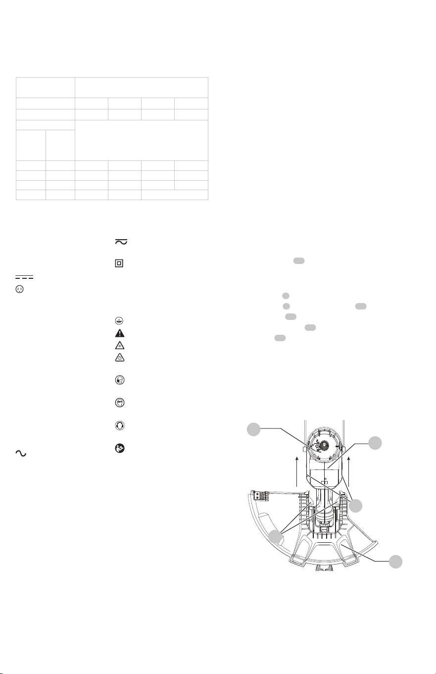
Attaching the Guard (Fig. C, D)
WARNING: NEVER OPERATE TRIMMER
WITHOUT GUARD FIRMLY IN PLACE.
1. Turn the trimmer upside down so that you are looking
down at the spool
10
.
2. Remove the screw from the guard with a
Phillipsscrewdriver.
3. Turn the guard
9
upside down and slide it fully onto the
motor housing
8
. Make sure the tabs
12
on the guard
engage the ribs
13
on the motor housing as shown in
Fig. D. The locking tab
14
should have snapped into the
housing slot
15
.
4. Continue to slide the guard on until you hear it “snap”
into place.
5. Insert the guard screw to complete the guard assembly.
6. Once the guard is installed, remove the covering from
the line cut-off blade, located on the edge of the guard.
minimum wire size. The following table shows the correct
size to use depending on cord length and nameplate
ampere rating. If in doubt, use the next heavier gauge. The
lower the gauge number, the heavier thecord.
Minimum gauge for Cord sets
Volts
Total length of Cord in Feet
(meters)
120 V 25 (7.6) 50 (15.2) 100 (30.5) 150 (45.7)
240 V 50 (15.2) 100 (30.5) 200 (61.0) 300 (91.4)
Ampere Rating
American Wire gauge
More
Than
not
More
Than
0 6 18 16 16 14
6 10 18 16 14 12
10 12 16 16 14 12
12 16 14 12 Not Recommended
12
Fig. C
10
8
13
9
Loading ...
Loading ...
Loading ...