Loading ...
Loading ...
Loading ...
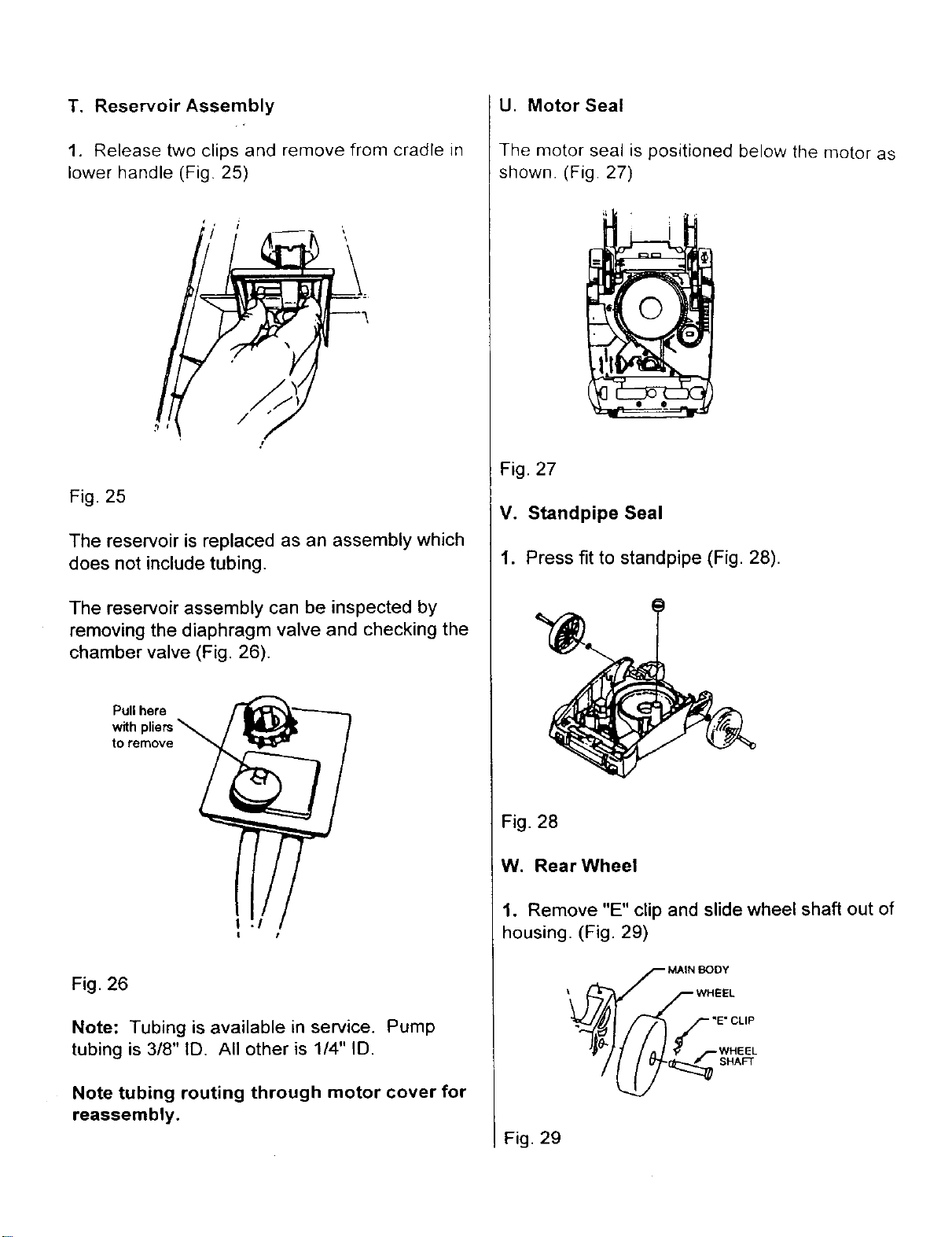
T. Reservoir Assembly
1. Release two clips and remove from cradle in
lower handle (Fig. 25)
Fig. 25
The reservoir is replaced as an assembly which
does not include tubing.
The reservoir assembly can be inspected by
removing the diaphragm valve and checking the
chamber valve (Fig. 26).
toremove __ /
t
Fig. 26
Note: Tubing is available in service. Pump
tubing is 3/8" ID. All other is 1/4" ID.
Note tubing routing through motor cover for
reassembly.
U. Motor Seal
The motor seal is positioned below the motor as
shown. (Fig. 27)
Fig. 27
V. Standpipe Seal
1. Press fit to standpipe (Fig. 28).
Fig. 28
W. Rear Wheel
1. Remove "E" clip and slide wheel shaft out of
housing. (Fig. 29)
F MAIN _)OY
Fig. 29
Loading ...
Loading ...
Loading ...