Loading ...
Loading ...
Loading ...
2. Remove (2)screws located at front of turbine.
3. Disconnect hose from turbine and lift out of
position.
K. Pump
1. Remove (1) screw located on pump
doghouse.
2. Release tab with flat blade screwdriver from
bottom of unit (Fig. 18).
Fig. 18
3. Disconnect hoses from pump.
L. Motor CoverNalve Assembly
1. Remove standpipe seal.
2. Remove (6) screws (Fig. 19)
3. To lift out of position flex outer walls of main
body to clear tabs.
4. Feed tubes through motor cover and remove.
M. Motor
1. Remove hood.
2. Remove recovery tank duct.
3. Remove hose connection at valve.
4. Remove valve lever.
5. Remove turbine assembly.
6. Remove motor cover/valve assembly.
7. Disconnect all lead wires.
8. Lift motor out of position.
Note: Motor is replaced as an assembly only.
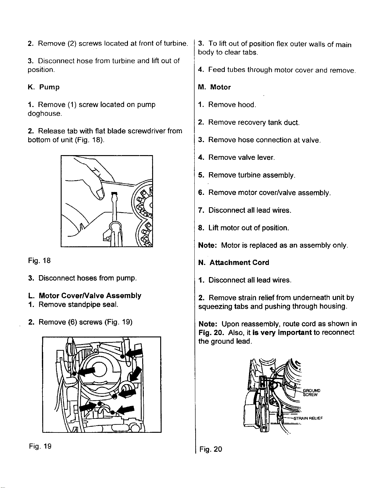
N. Attachment Cord
1. Disconnect all lead wires.
2. Remove strain relief from underneath unit by
squeezing tabs and pushing through housing.
Note: Upon reassembly, route cord as shown in
Fig. 20. Also, it is very important to reconnect
the ground lead.
Fig. 19 Fig. 20
Loading ...
Loading ...
Loading ...