Loading ...
Loading ...
Loading ...
1. Check polarity of battery posts. Battery case will be marked by each post: POSITIVE (POS, P,
+) and NEGATIVE (NEG, N, -).
Note: The positive battery post usually has a larger diameter than the negative post.
2. Attach a 24-inch long (or longer) 6-gauge (AWG) insulated battery cable to NEGATIVE (NEG,
N, -) battery post. The 24-inch cable is necessary to avoid the possibility of a spark over the top
of the battery. 6-gauge is recommended because it is readily available at your auto parts store.
3. Connect POSITIVE (RED) charger clip to POSITIVE (POS, P, +) post battery. Rock clip back
and forth to make good connection.
4. Position yourself and free end of 24 inch cable as far away from battery as possible. Then
connect NEGATIVE (BLACK) charger clip to free end of cable.
Warning: Do not face battery when making final connection. Rock clip back and forth to make a
good connection.
5. Select amperage.
6. Plug charger AC cord into a 120 volt grounded outlet.
7. Warning: Be sure area around battery is well ventilated while battery is being charged.
8. Continue charging battery until charger's ammeter needle shows half the rate of charge.
9. When battery is fully charged, unplug charger from AC power source.
10. When battery is fully charged and charger is unplugged,
1
st
remove clip from end of Negative end of cable, and,
2
nd
remove clip from Positive battery post, in that order.
11. Clean and store battery charger.
70549
- FIG 8
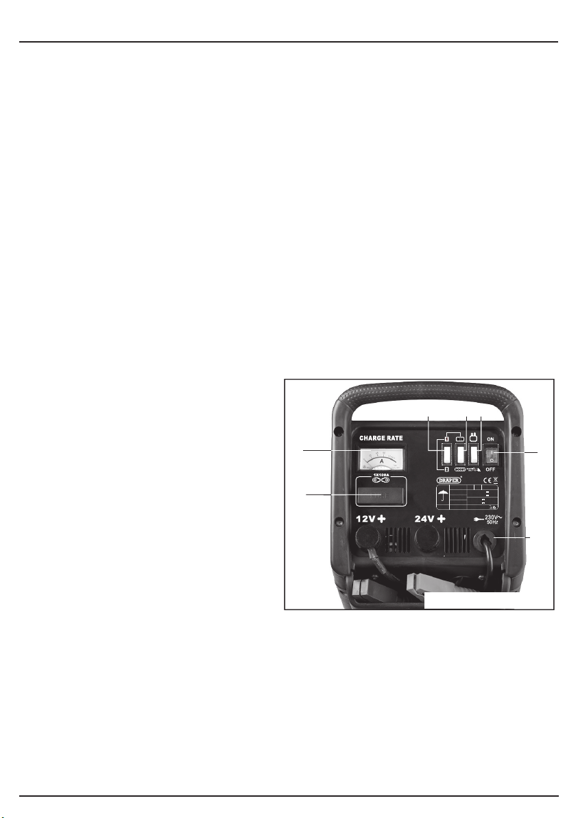
Output voltage selection is achieved by
connecting the positive (+) red clamp cable to
the appropriate terminal 12V or 24V.
Connect the cable to the terminal and securely
tighten locking knob.
Position switch to charge to select the
battery charging mode. The battery terminal not
connected to the chassis has to be connected
first. The other connection is to be made to the
chassis, remote from the battery and fuel line.
The battery charger is then to be connected to
the supply mains.
Position switch to the ON position to
begin current output. To select the one of the 4
output amperage/charge speed settings select
the switch combination as applicable.
Min. + 1 Low amperage/charge speed
Min. + 2 Medium/Low amperage/charge speed
Max. + 1 Medium/High amperage/charge speed
Max. + 2 High amperage/charge speed
Position switch to 1 or 2 and switch to MIN and observe the output current. Select the
combination with the output amperage approaching the 10% figure (5% for deep discharge).
Should the setting exceed 10% (5% for deep discharge) switch down until a suitable output is
attained and begin charging.
After charging, disconnect the battery charger from the supply mains. Then remove the chassis
connection and then the battery connection.
Stock No.70549
START
P. MAX
P.M A X
1.0KW
6.0KW
Output Fuse 100A x1
EN 60335-2-29
3s ON/120s OFF-5cycle
230V~1ph
50 Hz
U
1
CHARGE
START 12V
CHARGE 12V
Cmin 20 AhIP 20 cl H
30A
30A
CHARGE 24V
START 24V
180A(1V/e)
180A(1V/e)
FIG.8
Stock No.70549 shown
9. OPERATION AND USE
- 18 -
Loading ...
Loading ...
Loading ...