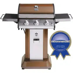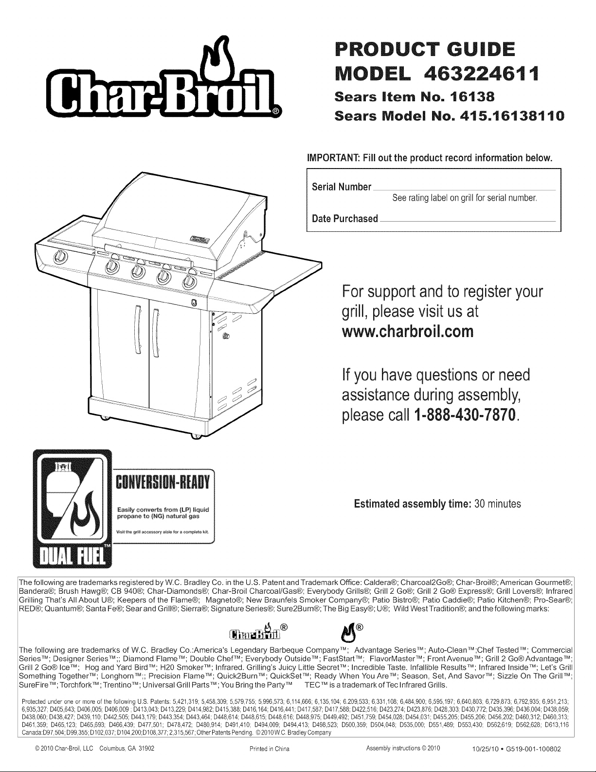
PRODUCT GUIDE
MODEL 46322461 t
Sears Item No, 16138
Sears Model No, 415,16138110
IMPORTANT: Fill out the product record information below.
Serial Number
Date Purchased
Seeratinglabelongrillfor serialnumber.
Forsupportandto registeryour
grill, pleasevisit us at
www.charbroil.com
If you havequestionsor need
assistanceduringassembly,
pleasecall 1-888-430-7870.
Estimated assembly time: 30 minutes
The following are trademarks registered by W.C. Bradley Co. in the U.S. Patent and Trademark Office: Caldera@; Charcoal2Go®; Char-Broil@; American Gourmet®;
Bandera®; Brush Hawg®; CB 940®; Char-Diamonds®; Char-Broil Charcoal/Gas@; Everybody Grills®; Grill 2 Go®; Grill 2 Go® Express®; Grill Lovers®; Infrared
Grilling That's All About U®; Keepers of the Flame®; Magneto@; New Braunfels Smoker Company®; Patio Bistro@; Patio Caddie®; Patio Kitchen®; Pro-Sear®;
RED@; Quantum@; Santa Fe@; Sear and Grill@; Sierra@; Signature Series®; Sure2Burn@; The Big Easy@; U@; Wild West Tradition@; and the following marks:
The following are trademarks of W.C. Bradley Co.:America's Legendary Barbeque CompanyTM; Advantage SeriesTM; Auto-Clean TM ;Chef Tested TM; Commercial
Series TM;Designer Series TM ;; Diamond Flame TM;Double ChefTM; Everybody Outside TM ; FastStartTM; FlavorMaster TM ; Front Avenue TM ; Grill 2 Go® Advantage TM;
Grill 2 Go® IceTM; Hog and Yard BirdTM; H20 SmokerTM; Infrared. Grilling's Juicy Little SecretTM; Incredible Taste. Infallible ResultsTM; Infrared InsideTM; Let's Grill
Something TogetherTM; LonghornTM;; Precision FlameTM; Quick2BurnTM; QuickSetTM; Ready When You AreTM; Season, Set, And SavorTM; Sizzle On The GrilITM;
SureFireTM; TorchforkTM ; TrentinoTM; Universal Grill PartsTM; You Bring the Party TM TEC TMis a trademark of Tec Infrared Grills.
Protected under one or more of the following U,S, Patents: 5,421,319;5,458,309; 5,579,755;5,996,573; 6,114,666;6,135,104;6,209,533;6,331,108; 6,484,900; 6,595,197;6,640,803;6,729,873; 6,792,935; 6,951,213;
6,935,327;D405,643;D406,005;D406,009 ; D413,043;D413,229;D414,982;D415,388;D416,164;D416,441;D417,587;D417,588;D422,516; D423,274;D423,876;D428,303;D430,772;D435,396;D436,004;D438,059;
D438,060;D438,427; D439,110;D442,505; D443,179;D443,354;D443,464;D448,614;D448,615; D448,616;D448,975;D449,492;D451,759;D454,028;D454,031; D455,205;D455,206;D456,202;D460,312; D460,313;
D461,359; D465,123; D465,693; D466,439; D477,501; D478,472; D480,914; D491,410; D494,009; D494,413; D498,523; D500,359; D504,048; D535,000; D551,489; D553,430; D562,619; D562,628; D613,116
Canada:D97,504;D99,355;D102,037;D104,200;D108,377;2,315,567;OtherPatentsPending,@2010W.C.BradleyCompany
@2010Char-Broil,LLC Columbus,GA 31902 Printed in China Assemblyinstructions@2010 10/25/10 QG519-001-100802
For Your Safety .................................... 2-3
Use and Care ..................................... 4-9
Limited Warranty .................................... 10
Parts List .......................................... 11
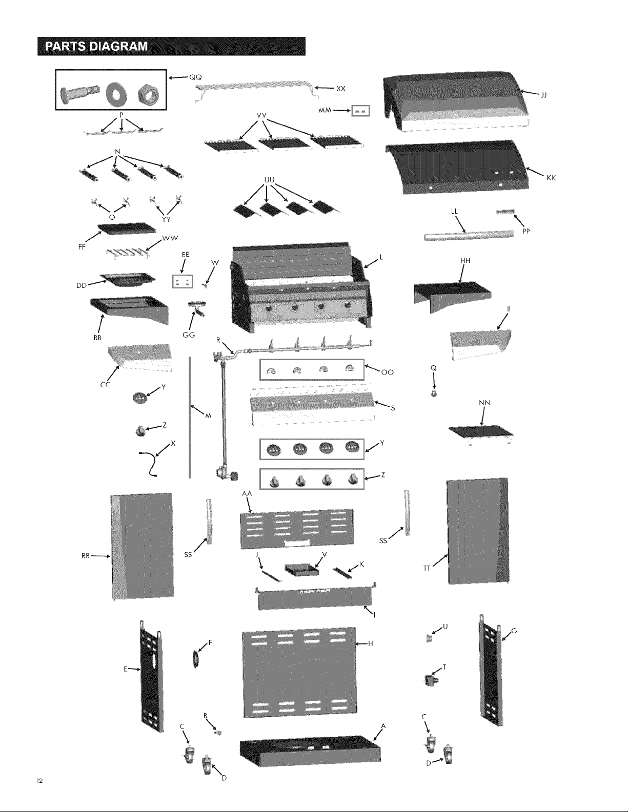
Parts Diagram...................................... 12
Assembly ....................................... 13-24
Troubleshooting .................................. 25-27
Registration Card ................................... 31
Safety Symbols
The symbols and boxesshown below explain what each heading
means. Read and follow all of the messages found throughout
the manual.
WARNING: Indicates an potentially hazardous situation
which, if not avoided, could result in death or serious injury.
CAUTioN
CAUTION: Indicatesa potentially hazardoussituation or
unsafe practicewhich, if not avoided, may result in minor
or moderate injury,
DANGER: Indicates an imminently hazardous situation
which, if not avoided, will result in death or serious injury.
If you smell gas:
1. Shut off gas to the appliance.
2. Extinguish any open flame.
3. Open lid.
4. If odor continues, keep away from the
appliance and immediately call your gas
supplier or your fire department.
1. Do not store or use gasoline or other
flammable liquids or vapors in the vicinity of
this or any other appliance.
2. An LP cylinder not connected for use shall not
be stored in the vicinity of this or any other
appliance.
CAUTION
For residential use only. Do not use for commercial
cooking.
CAUTION-
Read and follow all safety statements,assembly
instructions, and use and care directions before attempting
to assemble and cook.
|NSTALLER/ASSEMBLER:
Leave this manual with consumer.
CONSUMER"
Keep this manual for future reference.
WARNING=
Failure to follow all manufacturer's instructions could result
in serious personal injuryand/or property damage.
CAUTION:
Some parts may contain sharp edges - especially as noted
in the manual!Wear protective gloves if necessary.
CALIFORNIAPROPOSITION65
1.Combustionby-productsproducedwhenusing
thisproductcontainchemicalsknownto theStateof
Californiato causecancer,birthdefects,andother
reproductiveharm.
2.Thisproductcontainschemicals,including lead
and lead compounds, known to the State of
California to cause cancer, birth defects or other
reproductive harm.
Wash your hands after handling this product.
Installation Safety Precautions
* Use grill, as purchased, only with LP (propane) gas and the
regulator/valve assembly supplied. Ifyour grill is Dual Fuel ready,
a conversion kit must be purchased for use with natural gas.
, Grill installation must conform with local codes, or in their
absence of local codes, with either the National Fuel Gas
Code,ANSI Z223.1/NFPA 54, Natural Gas and Propane
Installation Code, CSA B149.1, or Propane Storage and
Handling Code, B149.2, or the Standard for Recreational
Vehicles,ANSI A 119.2/NFPA1192, and CSA Z240 RV Series,
Recreational Vehicle Code,as applicable.
, All electrical accessories (such as rotisserie) must be
electrically grounded in accordance with local codes, or
National Electrical Code,ANSI/NFPA 70 or Canadian
Electrical Code, CSA C22.1. Keep any electrical cords and/or
fuel supply hoses away from any hot surfaces.
o This grill is safety certified for use in the United States and/or
Canada only. Do not modify for use in any other location.
Modification will result in a safety hazard.
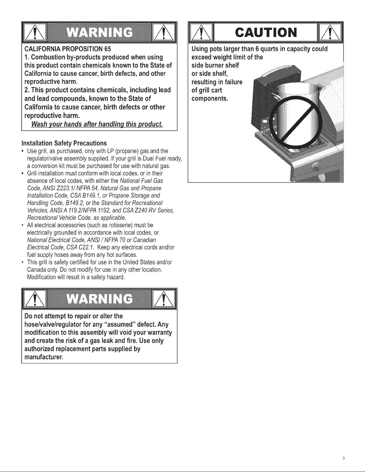
CAUTION
Using pots larger than 6 quarts in capacity could
exceed weight limit of the
side burner shelf
or side shelf,
resulting in failure
of grill cart
components.
Do not attempt to repair or alter the
hoseNalve/regulator for any "assumed" defect. Any
modification to this assembly will void your warranty
and create the risk of a gas leak and fire. Use only
authorized replacement parts supplied by
manufacturer.
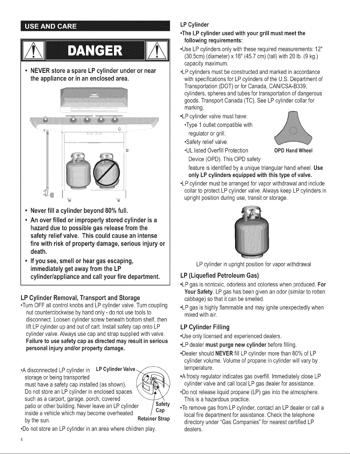
• NEVERstore a spare LP cylinder under or near
the appliance or in an enclosed area.
• Never fill a cylinder beyond 80% full.
• An over filled or improperly stored cylinder is a
hazard due to possible gas release from the
safety relief valve. This could cause an intense
fire with risk of property damage, serious injury or
death.
If you see, smell or hear gas escaping,
immediatelyget away from the LP
cylindedappliance and call your fire department.
LP Cylinder Removal, Transport and Storage
•Turn OFF all control knobs and LP cylinder valve. Turn coupling
nut counterclockwise by hand only - do not use tools to
disconnect. Loosen cylinder screw beneath bottom shelf, then
lift LP cylinder up and out of cart. Install safety cap onto LP
cylinder valve. Always use cap and strap supplied with valve.
Failure to use safety cap as directed may result in serious
personal injury and/or property damage.
•Adisconnected LP cylinder in LPCylinder
storage or being transported
must have a safety cap installed (as shown).
Do not store an LP cylinder in enclosed spaces
such as a carport, garage, porch, covered
patio or other building. Never leave an LP cylinder Safety
inside a vehicle which may become overheated Cap
by the sun. RetainerStrap
•Do not store an LP cylinder in an area where children play.
LP Cylinder
•The LP cylinder used with your grill must meet the
following requirements:
•Use LP cylinders only with these required measurements: 12"
(30.5cm) (diameter) x 18" (45.7 cm) (tall) with 20 lb. (9 kg.)
capacity maximum.
•LP cylinders must be constructed and marked in accordance
with specifications for LP cylinders of the U.S. Department of
Transportation (DOT) or for Canada, CAN/CSA-B339,
cylinders, spheres and tubes for transportation of dangerous
goods. Transport Canada (TC). See LP cylinder collar for
marking.
•LP cylinder valve must have:
•Type 1 outlet compatible with
regulator or grill.
•Safety relief valve.
•UL listed Overfill Protection OPDHandWheel
Device (OPD). This OPD safety
feature is identified by a unique triangular hand wheel. Use
only LP cylinders equipped with this type of valve.
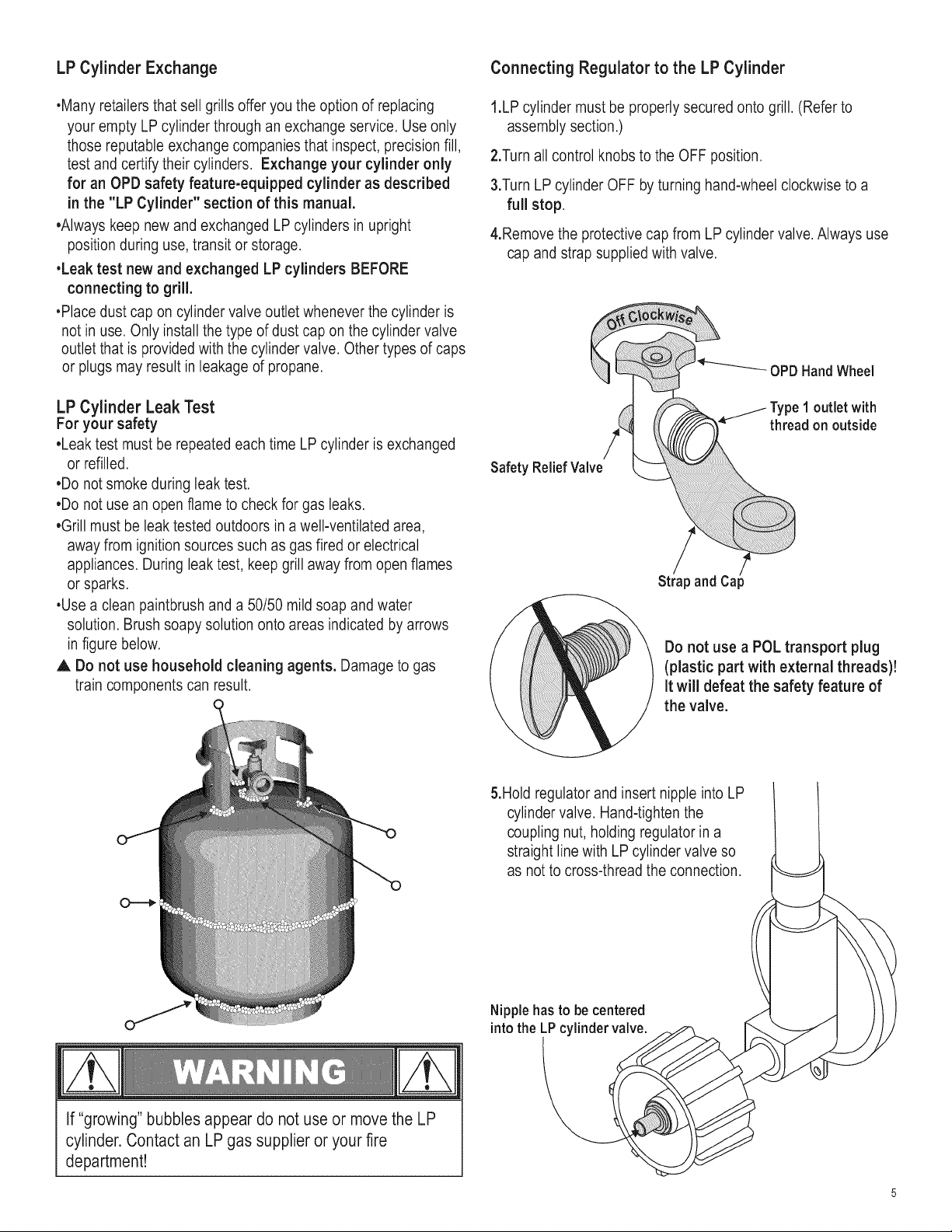
•LP cylinder must be arranged for vapor withdrawal and include
collar to protect LP cylinder valve. Always keep LP cylinders in
upright position during use, transit or storage.
LP cylinder in upright )osition for vapor withdrawal
LP (Liquefied Petroleum Gas)
•LP gas is nontoxic, odorless and colorless when produced. For
Your Safety, LP gas has been given an odor (similar to rotten
cabbage) so that it can be smelled.
•LP gas is highly flammable and may ignite unexpectedly when
mixedwith air.
LP Cylinder Filling
•Use only licensed and experienced dealers.
•LP dealer must purge new cylinder before filling.
•Dealer should NEVER fill LP cylinder more than 80% of LP
cylinder volume. Volume of propane in cylinder will vary by
temperature.
•A frosty regulator indicates gas overfill. Immediately close LP
cylinder valve and call local LP gas dealer for assistance.
•Do not release liquid propane (LP) gas into the atmosphere.
This is a hazardous practice.
•To remove gas from LP cylinder, contact an LP dealer or call a
local fire department for assistance. Check the telephone
directory under "Gas Companies" for nearest certified LP
dealers.
LP Cylinder Exchange Connecting Regulator to the LP Cylinder
•Many retailers that sell grills offer you the option of replacing
your empty LP cylinder through an exchange service. Use only
those reputable exchange companies that inspect, precision fill,
test and certify their cylinders. Exchange your cylinder only
for an OPD safety feature-equipped cylinder as described
in the "LP Cylinder" section of this manual.
•Always keep new and exchanged LP cylinders in upright
position during use, transit or storage.
•Leak test new and exchanged LP cylinders BEFORE
connecting to grill.
•Place dust cap on cylinder valve outlet whenever the cylinder is
not in use. Only install the type of dust cap on the cylinder valve
outlet that is provided with the cylinder valve. Other types of caps
or plugs may result in leakage of propane.
LP Cylinder Leak Test
For your safety
•Leak test must be repeated each time LP cylinder is exchanged
or refilled.
•Do not smoke during leak test.
•Do not use an open flame to check for gas leaks.
•Grill must be leak tested outdoors in a well-ventilated area,
away from ignition sources such as gas fired or electrical
appliances. During leak test, keep grill away from open flames
or sparks.
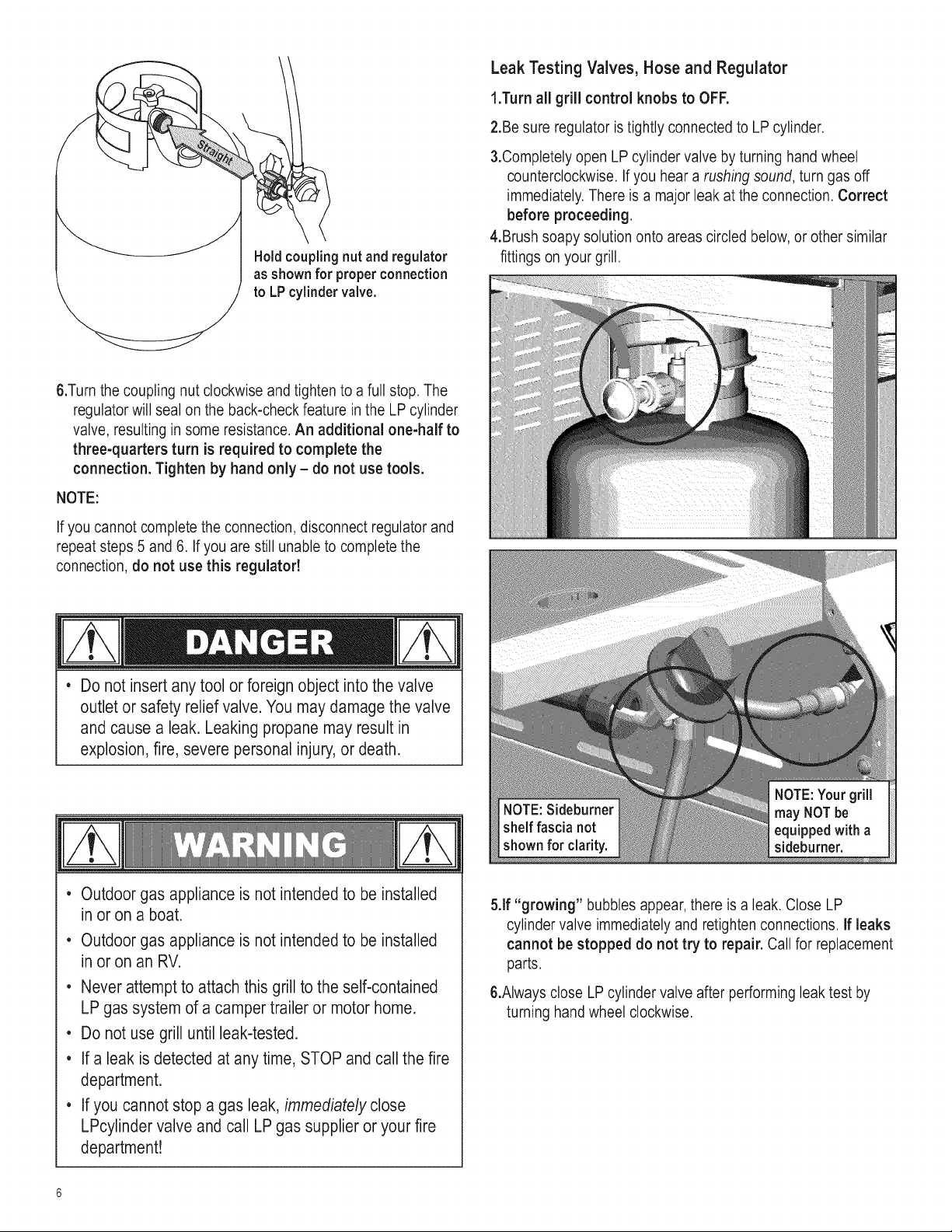
•Use a clean paintbrush and a 50/50 mild soap and water
solution. Brush soapy solution onto areas indicated by arrows
in figure below.
A Do not use household cleaning agents. Damage to gas
train components can result.
1.LP cylinder must be properly secured onto grill. (Refer to
assembly section.)
2.Turn all control knobs to the OFF position.
3.TurnLP cylinder OFF by turning hand-wheel clockwise to a
full stop.
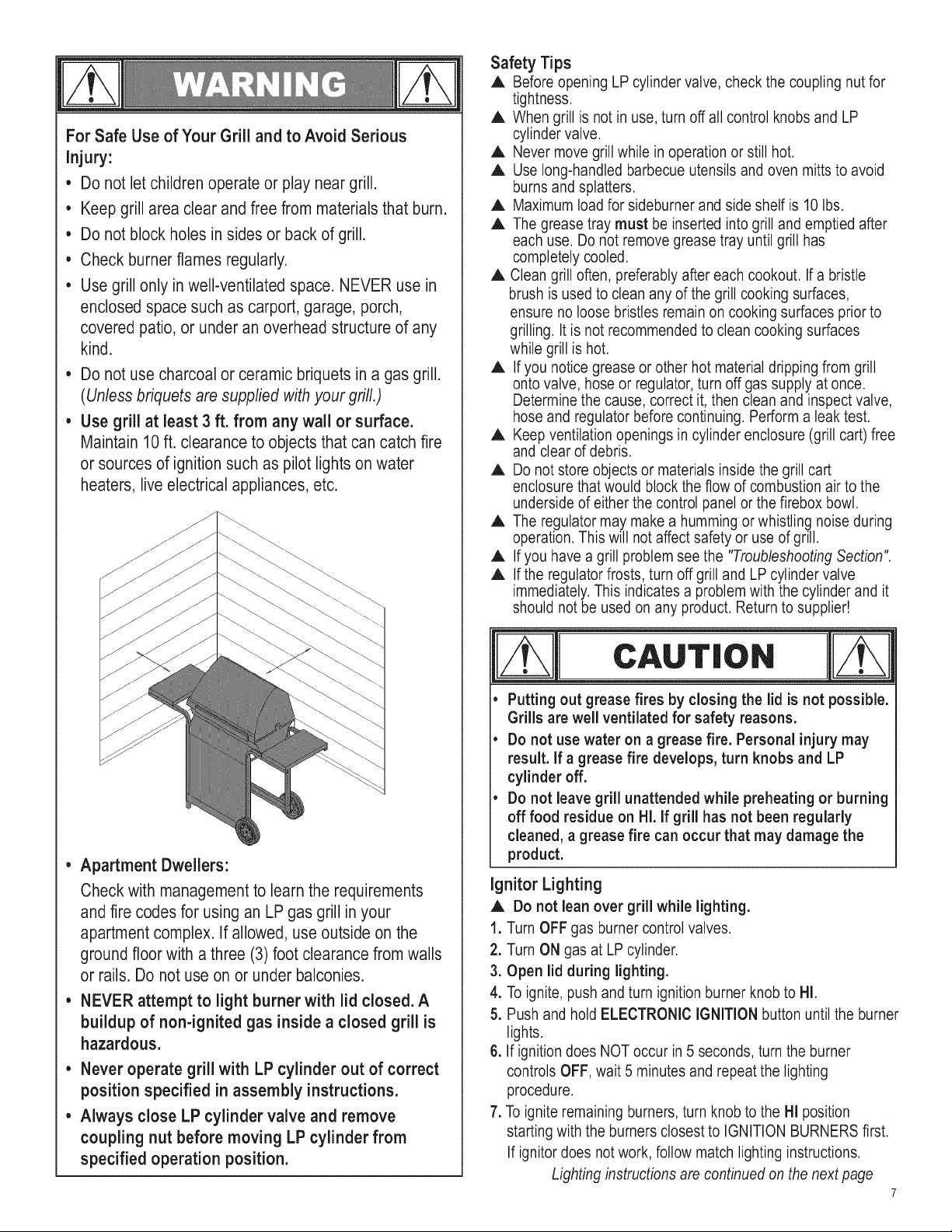
4.Remove the protective cap from LP cylinder valve. Always use
cap and strap supplied with valve.
OPDHandWheel
j Type1 outlet with
thread on outside
Safety ReliefValve
!
Strap and Cap
Do not use a POL transport plug
(plastic part with external threads)!
It will defeat the safety feature of
the valve.
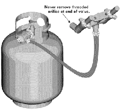
5.Hold regulator and insert nipple into LP
cylinder valve. Hand-tighten the
coupling nut, holding regulator in a
straight line with LP cylinder valve so
as not to cross-thread the connection.
Nipple has to be centered
intothe LP cylinder valve.
If "growing" bubbles appear do not use or move the LP
cylinder. Contact an LP gas supplier or your fire
department!
Hold coupling nut and regulator
as shown for properconnection
to LP cylinder valve.
Leak Testing Valves, Hose and Regulator
1.Turn all grill control knobs to OFF.
2.Be sure regulator is tightly connected to LP cylinder.
3.Completely open LP cylinder valve by turning hand wheel
counterclockwise. If you hear a rushing sound, turn gas off
immediately. There is a major leak at the connection. Correct
before proceeding.
4.Brush soapy solution onto areas circled below, or other similar
fittings on your grill.
6.Turn the coupling nut clockwise and tighten to a full stop. The
regulator will seal on the back-check feature in the LP cylinder
valve, resulting in some resistance. An additional one-half to
three-quarters turn is required to complete the
connection. Tighten by hand only - do not use tools.
NOTE:
If you cannot complete the connection, disconnect regulator and
repeat steps 5 and 6. If you are still unable to complete the
connection, do not use this regulator!
Do not insert any tool or foreign object into the valve
outlet or safety relief valve. You may damage the valve
and cause a leak. Leaking propane may result in
explosion,fire, severe personal injury,or death.
Outdoor gas appliance is not intended to be installed
in or on a boat.
Outdoor gas appliance is not intended to be installed
in or on an RV.
, Never attempt to attach this grill to the self-contained
LP gas system of a camper trailer or motor home.
, Do not use grill until leak-tested.
, If a leak is detected at any time, STOP and call the fire
department.
, If you cannot stop a gas leak, immediately close
LPcylinder valve and call LP gas supplier or your fire
department!
5.If "growing" bubbles appear, there is a leak. Close LP
cylinder valve immediately and retighten connections. If leaks
cannot be stopped do not try to repair. Call for replacement
parts.
6.Always close LPcylinder valve after performing leak test by
turning hand wheel clockwise.
For Safe Use of YourGrill and to Avoid Serious
injury:
• Do not let children operate or play near grill.
• Keep grill area clear and free from materials that burn.
• Do not block holes in sides or back of grill.
• Check burnerflames regularly.
• Use grill only inwell-ventilated space. NEVER use in
enclosed space such as carport, garage, porch,
covered patio, or under an overhead structure of any
kind.
Do not use charcoal or ceramic briquets in a gas grill.
(Unless briquets are supplied with your grill.)
Use grill at least 3 ft. from any wall or surface.
Maintain 10 ft. clearance to objects that can catch fire
or sources of ignition such as pilot lights on water
heaters, live electrical appliances, etc.
• Apartment Dwellers:
Check with managementto learn the requirements
and fire codes for using an LP gas grill in your
apartment complex. If allowed, use outside on the
ground floor with a three (3) foot clearance from walls
or rails. Do not use on or under balconies.
• NEVER attempt to light burner with lid closed.A
buildup of non-ignited gas inside a closed grill is
hazardous.
• Never operate grill with LP cylinder out of correct
positionspecified in assembly instructions.
• Always close LP cylinder valve and remove
coupling nut before moving LP cylinder from
specified operation position.
Safety Tips
A Before opening LP cylinder valve, check the coupling nut for
tightness.
A When grill is not in use, turn off all control knobs and LP
cylinder valve.
A Never move grill while in operation or still hot.
A Use long-handled barbecue utensils and oven mitts to avoid
burns and splatters.
A Maximum load for sideburner and side shelf is 10 Ibs.
A The grease tray must be inserted into grill and emptied after
each use. Do not remove grease tray until grill has
completely cooled.
A Clean grill often, preferably after each cookout. If a bristle
brush is used to clean any of the grill cooking surfaces,
ensure no loose bristles remain on cooking surfaces prior to
grilling. It is not recommended to clean cooking surfaces
while grill is hot.
A If you notice grease or other hot material dripping from grill
onto valve, hose or regulator, turn off gas supply at once.
Determine the cause, correct it, then clean and inspect valve,
hose and regulator before continuing. Perform a leak test.
A Keep ventilation openings in cylinder enclosure (grill cart) free
and clear of debris.
A Do not store objects or materials inside the grill cart
enclosure that would block the flow of combustion air to the
underside of either the control panel or the firebox bowl.
A The regulator may make a humming or whistling noise during
operation. This will not affect safety or use of grill.
A If you have a grill problem see the "Troubleshooting Section".
A If the regulator frosts, turn off grill and LP cylinder valve
immediately. This indicates a problem with the cylinder and it
should not be used on any product. Return to supplier!
CAUT'O.
• Putting out grease fires by closing the lid is not possible.
Grills are well ventilated for safety reasons.
• Do not use water on a grease fire. Personal injury may
result, if a grease fire develops, turn knobs and LP
cylinder off.
• Do not leave grill unattended while preheating or burning
off food residue on HI. if grill has not been regularly
cleaned, a grease fire can occur that may damage the
product.
ignitor Lighting
A Do not lean over grill while lighting.
1. Turn OFF gas burner control valves.
2. Turn ON gas at LP cylinder.
3. Open lid during lighting.
4. To ignite, push and turn ignition burner knob to HI.
5. Push and hold ELECTRONIC IGNITION button until the burner
lights.
6. If ignition does NOT occur in 5 seconds, turn the burner
controls OFF, wait 5 minutes and repeat the lighting
procedure.
7. To ignite remaining burners, turn knob to the HI position
starting with the burners closest to IGNITION BURNERS first.
If ignitor does not work, follow match lighting instructions.
Lighting instructions are continued on the next page
7
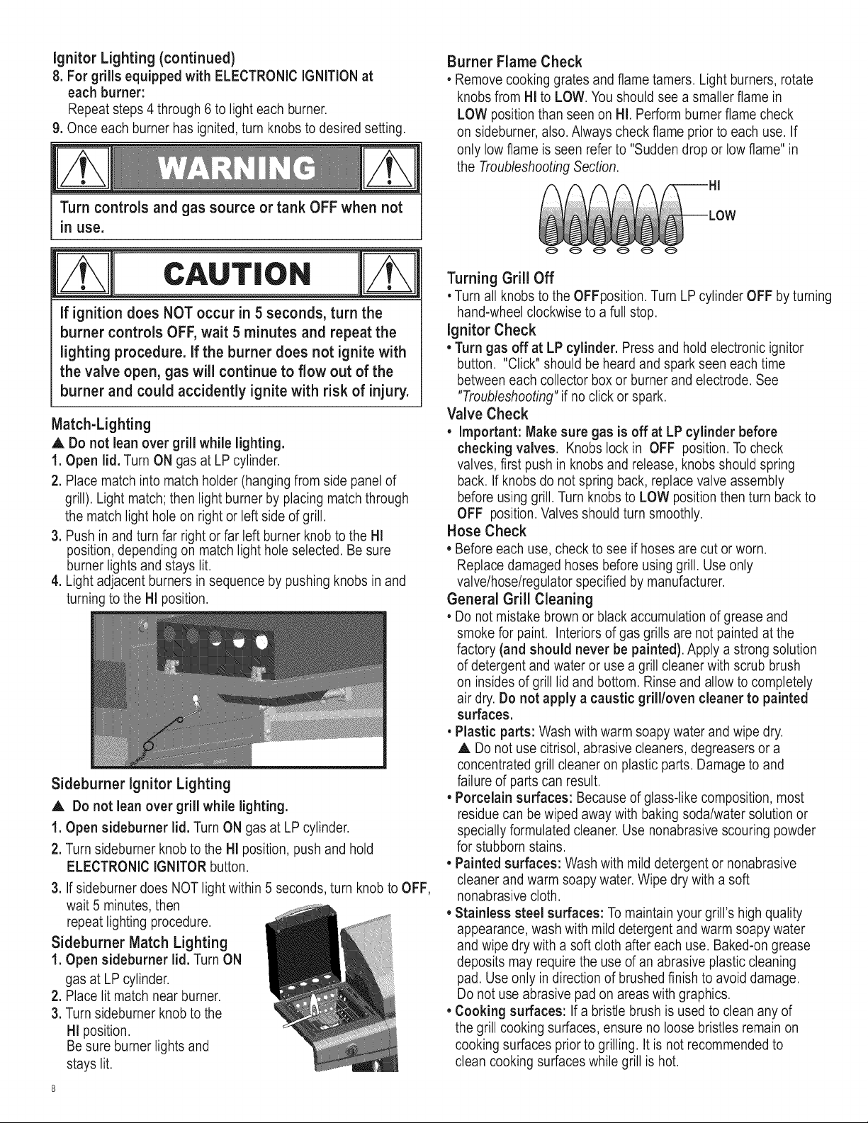
Ignitor Lighting (continued)
8. For grills equipped with ELECTRONIC IGNITION at
each burner:
Repeat steps 4 through 6 to light each burner.
9. Once each burner has ignited, turn knobs to desired setting.
Turn controls and gas source or tank OFF when not
in use.
cAuT,o.
If ignition does NOT occur in 5 seconds, turn the
burner controls OFF, wait 5 minutes and repeat the
lighting procedure. If the burner does not ignite with
the valve open, gas will continue to flow out of the
burner and could accidently ignite with risk of injury.
Match-Lighting
,& Do not lean over grill while lighting.
1. Open lid. Turn ON gas at LP cylinder.
2. Place match into match holder (hanging from side panel of
grill). Light match; then light burner by placing match through
the match light hole on right or left side of grill.
3. Push in and turn far right or far left burner knob to the HI
position, depending on match light hole selected. Be sure
burner lights and stays lit.
4. Light adjacent burners in sequence by pushing knobs in and
turning to the HI position.
Sideburner ignitor Lighting
A Do not lean over grill while lighting.
1. Open sideburner lid. Turn ON gas at LP cylinder.
2. Turn sideburner knob to the Hi position, push and hold
ELECTRONIC IGNITOR button.
3. If sideburner does NOT light within 5 seconds, turn knob to OFF,
wait 5 minutes, then
repeat lighting procedure.
Sideburner Match Lighting
1. Open sideburner lid. Turn ON
gas at LP cylinder.
2. Place lit match near burner.
3. Turn sideburner knob to the
HI position.
Be sure burner lights and
stays lit.
8
Burner Flame Check
• Remove cooking grates and flame tamers. Light burners, rotate
knobs from Hi to LOW. Youshould see a smaller flame in
LOW position than seen on HI. Perform burner flame check
on sideburner, also. Always check flame prior to each use. If
only low flame is seen refer to "Sudden drop or low flame" in
the Troubleshooting Section.
Turning Grill Off
• Turn all knobs to the OFFposition. Turn LP cylinder OFF by turning
hand-wheel clockwise to a full stop.
Ignitor Check
• Turn gas off at LP cylinder. Press and hold electronic ignitor
button. "Click" should be heard and spark seen each time
between each collector box or burner and electrode. See
"Troubleshooting" if no click or spark.
Valve Check
• important: Make sure gas is off at LP cylinder before
checking valves. Knobs lock in OFF position. To check
valves, first push in knobs and release, knobs should spring
back. If knobs do not spring back, replace valve assembly
before using grill. Turn knobs to LOW position then turn back to
OFF position. Valves should turn smoothly.
Hose Check
• Before each use, check to see if hoses are cut or worn.
Replace damaged hoses before using grill. Use only
valve/hose/regulator specified by manufacturer.
General Grill Cleaning
• Do not mistake brown or black accumulation of grease and
smoke for paint. Interiors of gas grills are not painted at the
factory (and should never be painted). Apply a strong solution
of detergent and water or use a grill cleaner with scrub brush
on insides of grill lid and bottom. Rinse and allow to completely
air dry. Do not apply a caustic grill/oven cleaner to painted
surfaces.
• Plastic parts: Wash with warm soapy water and wipe dry.
A Do not use citrisol, abrasive cleaners, degreasers or a
concentrated grill cleaner on plastic parts. Damage to and
failure of parts can result.
• Porcelain surfaces: Because of glass-like composition, most
residue can be wiped away with baking soda/water solution or
specially formulated cleaner. Use nonabrasive scouring powder
for stubborn stains.
• Painted surfaces: Wash with mild detergent or nonabrasive
cleaner and warm soapy water. Wipe dry with a soft
nonabrasive cloth.
• Stainless steel surfaces: To maintain your grill's high quality
appearance, wash with mild detergent and warm soapy water
and wipe dry with a soft cloth after each use. Baked-on grease
deposits may require the use of an abrasive plastic cleaning
pad. Use only in direction of brushed finish to avoid damage.
Do not use abrasive pad on areas with graphics.
• Cooking surfaces: If a bristle brush is used to clean any of
the grill cooking surfaces, ensure no loose bristles remain on
cooking surfaces prior to grilling. It is not recommended to
clean cooking surfaces while grill is hot.
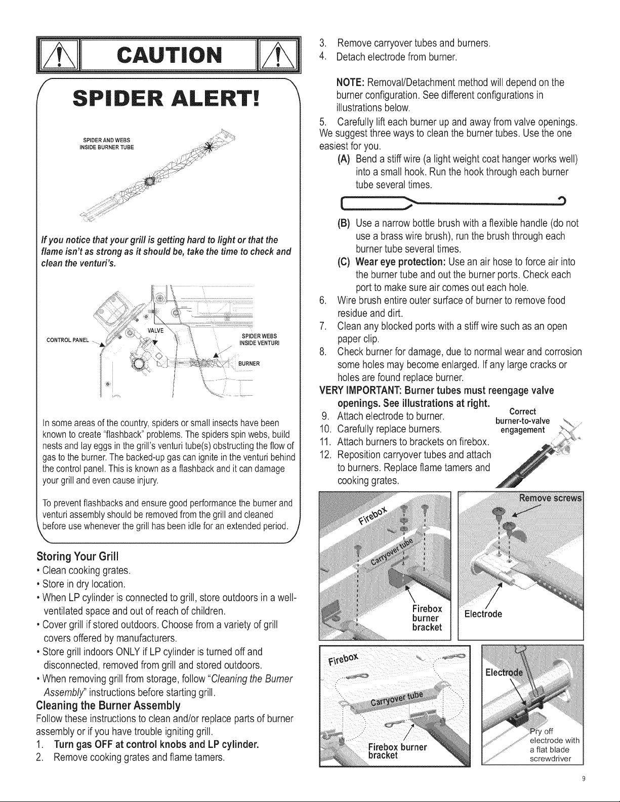
cAuTioN
f
SPIDER ALERT!
If you notice thatyour grill is getting hard to light or thatthe
flame isn't as strong as it should be, takethe time to check and
clean the ventud's.
CONTROLPANEL
sPIDER WEBS
INSIDE VENTURI
!
i BURNER
In someareasof the country,spidersor smallinsectshavebeen
knownto create"flashback"problems.The spidersspinwebs,build
nestsand layeggs in the grill'sventuritube(s)obstructingthe flow of
gasto the burner.Thebacked-upgascan ignitein the venturibehind
thecontrolpanel.Thisis knownasa flashbackandit candamage
yourgrillandevencauseinjury.
Topreventflashbacksand ensuregoodperformancethe burnerand
venturiassemblyshouldbe removedfromthe grillandcleaned
_b,,eforeusewheneverthe grill hasbeenidlefor anextendedperiod, j
J
Storing Your Grill
• Clean cooking grates.
• Store in dry location.
• When LP cylinder is connected to grill, store outdoors in a well-
ventilated space and out of reach of children.
• Cover grill if stored outdoors. Choose from a variety of grill
covers offered by manufacturers.
• Store grill indoors ONLY if LP cylinder is turned off and
disconnected, removed from grill and stored outdoors.
• When removing grill from storage, follow "Cleaning the Burner
Assembly" instructions before starting grill.
Cleaning the Burner Assembly
Follow these instructions to clean and/or replace parts of burner
assembly or if you have trouble igniting grill.
1. Turn gas OFF at control knobs and LP cylinder,
2. Remove cooking grates and flame tamers.
3. Remove carryover tubes and burners.
4. Detach electrode from burner.
NOTE: Removal/Detachment method will depend on the
burner configuration. See different configurations in
illustrations below.
5. Carefully lift each burner up and away from valve openings.
We suggest three ways to clean the burner tubes. Use the one
easiest for you.
(A) Bend a stiff wire (a light weight coat hangerworks well)
into a small hook. Run the hook through each burner
tube several times.
r.._.,... _-
(B) Use a narrow bottle brush with a flexible handle (do not
use a brass wire brush), run the brush through each
burner tube several times.
(C) Wear eye protection: Use an air hose to force air into
the burner tube and out the burner ports. Check each
port to make sure air comes out each hole.
6. Wire brush entire outer surface of burner to remove food
residue and dirt.
7. Clean any blocked ports with a stiff wire such as an open
paper clip.
8. Check burner for damage, due to normal wear and corrosion
some holes may become enlarged. If any large cracks or
holes are found replace burner.
VERY IMPORTANT:Burner tubes must reengage valve
openings. See illustrations at right.
9. Attach electrode to burner. Correct
burner-to-valve
10. Carefully replace burners, engagement
11. Attach burners to brackets on firebox.
12. Reposition carryover tubes and attach
to burners. Replace flame tamers and
cooking grates.
bracket
Firebox
burner Electrode
bracket
screwdriver
This warranty only applies to units purchased fiom an authorized retailer. ManuPacturer warrants to the original cunsumer-purchaser only that this
product shall be fiec from defects in workmanship and materials alter correct assembly and under normal and reasonable home use for the periods
indicated below beginning on the date of purchase*. The manuPacturer reserves the right to require that defective parts be returned, postage and or
freight pre-paid by the consumer for review and examination.
SCOPE OF COVERAGE PERIOD OF COVERAGE TYPE OF FAILURE COVERAGE
Burner
Firebox
All Other Parts
3 ,/ears from date of purchase*
2 years from date of purchase*
l year from date of purchase*
PERFORATION, MANUFACTURING,
AND MATERIAL DEFECTS ONLY
*Note: A dated sales reciept WILL be required for walTanty service.
The original consumer-purchaser will be responsible for all shipping charges for parts replaced under the terms of this limited warranty.
This limited warranty is applicable in the United States and Canada only; is only available to the original owner of the product and is not transferable.
Manufacturer requires proof of your date of purchase. Theretbre, you should retain your sales slip or invoice. Registering your product is not a
substitute for proof of purchase and the manuPacturer is not responsible for or required to retain proof of purchase records.
This limited wananty applies to the functionality of the product ONLY and does not cover cosmetic issues such as scratches, dents, corrosions or
discoloring by heat, abrasive and chemical cleaners or any tools used in the assembly or installation of the appliance, surt:ace rust, or the
discoloration of stainless steel surfiaces. RUST is not considered a manufacturing or materials defect.
This limited warranty will not reimburse you for the cost of any inconvenience, food, personal injury or property damage.
ITEMS MAN UFACTURER WILL NOT PAY FOR:
1. Shipping cost, standard or expedited, for warranty and replacement parts
2. Service calls to your home.
3. Repairs when your product is used for other than normal, single-family household or residential use.
4. Damage, failures, or operating difficulties resulting from accident, alteration, careless handling, misuse, abuse, fire, flood,
acts of God, improper installation or maintenance, installation not in accordance with electrical or plmnbing codes, or use
of products not approved by the manufacturer.
5. Any food loss due to product failures or operating difficulties.
6. Replacement parts or repair labor costs for units operated outside the United States or Canada.
7. Pickup and delivery of your product.
8. Repairs to parts or systems resulting from unauthorized modifications made to the product.
9. The removal and/or reinstallation of your product.
DISCLAIMER OF IMPLIED WARRANTIES and LIMITATION OF REMEDIES
Repair or replacement of defective parts is your exclusive remedy under the terms of this limited warranty. In the event of parts availability issues,
the manufacturer reserves the right to substitute like or similar parts that are equally functional.
Manufacturer will not be responsible for any consequential or incidental damages arising fiom the breach of either this limited warranty or any
applicable implied warranty; or for failure or damage resulting from acts of God, improper care and maintenance, grease fire, accident, alteration,
replacement of parts by anyone other than Manufacturer, misuse, transportation, commercial use, abuse, hostile environments (inclement weather,
acts of nature, animal tampering), improper installation or installation not in accordance with local codes or printed manufacturer instructions.
THIS LIMITED WARRANTY IS THE SOLE EXPRESS WARRANTY GIVEN BY THE MANUFACTURER. NO PRODUCT PERFORMANCE
SPECIFICATION OR DESCRIPTION WHEREVER APPEARING IS WARRANTED BY MANUFACTURER EXCEPT TO THE EXTENT SET
FORTH IN THIS LIMITED WARRANTY. ANY IMPLIED WARRANTY PROTECTION ARISING UNDER THE LAWS OF ANY S'IWFE,
INCLUDING IMPLIED WARRANTY OF MERCHANTABILITY OR FITNESS FOR A PAt_FICULAR PURPOSE OR USE, IS HEREBY
LIMITED IN DURATION TO THE DURATION OF THIS LIMITED WARRANTY.
Neither dealers nor the retail establishment selling this product has any authority to make any additional warranties or to promise remedies
in addition to or inconsistent with those stated above. Manufacturer's maxhnum liability, in any event, shall not exceed the purchase price of the
product paid by the original consumer.
NOTE: Some states do not allow an exclusion or limitation of incidental or consequential damages, so some of the above limitations or exclusions
may not apply to you. This limited warranty gives you specific legal rights as set foth herein. You may also have other rights which vary from state
to state. In the state of California only; if refinishing or replacement of the product is not commercially practicable, the retailer selling this product or
the Manufacturer will refund the purchase price paid for the product, less the amount directly attributable to use by the original consumer-purchaser
prior to discovery of the nonconformity. In addition, in the state of California only; you may take the product to the retail establishment selling this
product in order to obtain performance under this limited wananty.
if you wish to obtain performance of any obligation under this limited warranty, you should
write to:
Consumer Relations
P. O. Box 1240
Columbus, GA 31902-1240
Consumer returns will not be accepted unless a valid Return Authorization is first acquired. Authorized returns are clearly marked on the outside of
the package with an RA number and the package is shipped freight/postage pre-paid. Consumer returns that do not meet these standards will be
refused.
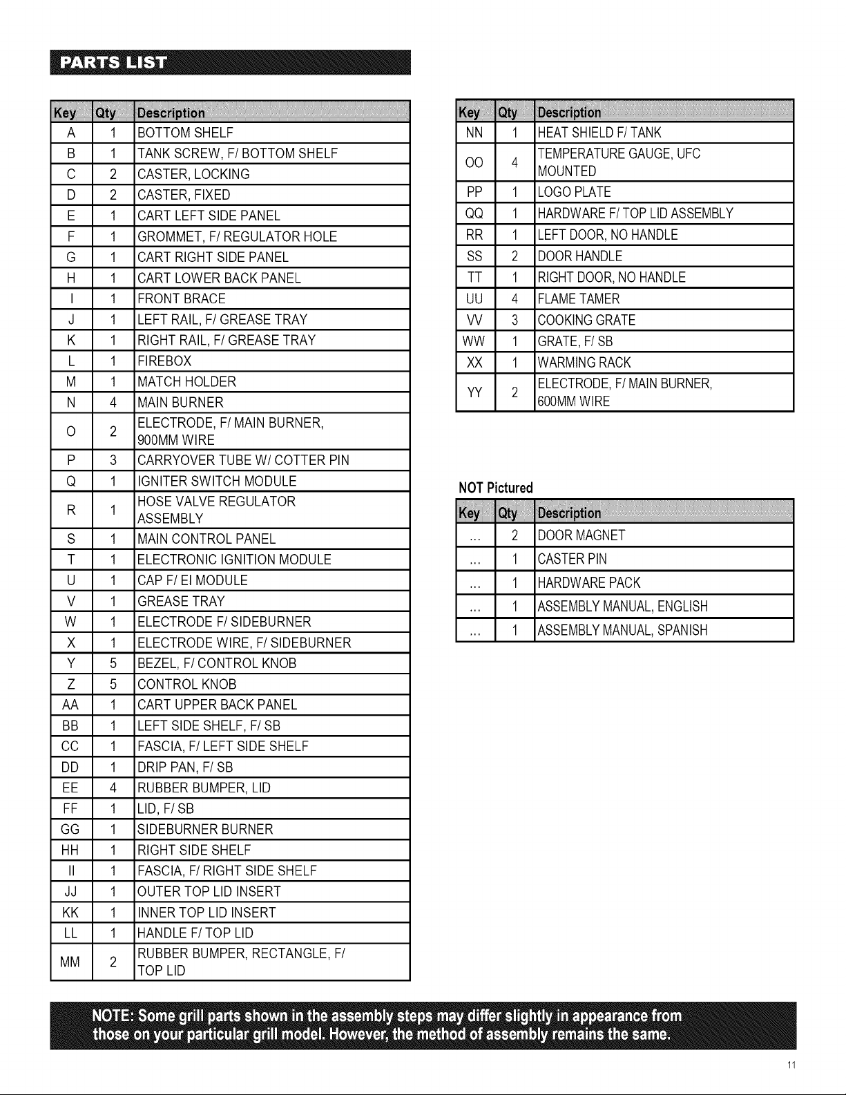
A 1 BOTTOM SHELF
B 1 TANK SCREW, F/BOTTOM SHELF
C 2 CASTER, LOCKING
D 2 CASTER, FIXED
E 1 CART LEFT SIDE PANEL
F 1 GROMMET, F/REGULATOR HOLE
G 1 CART RIGHT SIDE PANEL
H 1 CART LOWER BACK PANEL
I 1 FRONT BRACE
J 1 LEFT RAIL, F/GREASE TRAY
K 1 RIGHT RAIL, F/GREASE TRAY
L 1 FIREBOX
M 1 MATCH HOLDER
N 4 MAIN BURNER
O 2 ELECTRODE, F/MAIN BURNER,
900MM WIRE
P 3 CARRYOVER TUBE W/COTTER PIN
Q 1 IGNITER SWITCH MODULE
HOSEVALVE REGULATOR
R 1
ASSEMBLY
S 1 MAIN CONTROL PANEL
T 1 ELECTRONIC IGNITION MODULE
U 1 CAP F/El MODULE
V 1 GREASE TRAY
W 1 ELECTRODE F/SlDEBURNER
X 1 ELECTRODE WIRE, F/SlDEBURNER
Y 5 BEZEL, F/CONTROL KNOB
Z 5 CONTROL KNOB
AA 1 CART UPPER BACK PANEL
BB 1 LEFT SIDE SHELF, F/SB
CC 1 FASCIA, F/LEFT SIDE SHELF
DD 1 DRIP PAN, F/SB
EE 4 RUBBER BUMPER, LID
FF 1 LID, F/SB
GG 1 SlDEBURNER BURNER
HH 1 RIGHT SIDE SHELF
II 1 FASCIA, F/RIGHT SIDE SHELF
JJ 1 OUTER TOP LID INSERT
KK 1 INNER TOP LID INSERT
LL 1 HANDLE F/TOP LID
RUBBER BUMPER, RECTANGLE, F/
MM 2
TOP LID
NN 1 HEAT SHIELDF/TANK
TEMPERATUREGAUGE,UFC
CO 4
MOUNTED
PP 1 LOGO PLATE
QQ 1 HARDWAREF/TOP LID ASSEMBLY
RR 1 LEFT DOOR,NO HANDLE
SS 2 DOORHANDLE
TT 1 RIGHT DOOR,NO HANDLE
UU 4 FLAMETAMER
VV 3 COOKINGGRATE
WW 1 GRATE,F/SB
XX 1 WARMINGRACK
YY 2 ELECTRODE,F/MAIN BURNER,
600MMWIRE
NOTPictured
,,, 2
iiii!ilii!i!iliiliil llllllllllllllllllllllllllllllllllllllllllllll
DOORMAGNET
CASTERPIN
HARDWAREPACK
ASSEMBLYMANUAL,ENGLISH
ASSEMBLYMANUAL,SPANISH
11
I
N
©
j_
FF
¥Y
EE
/
BB
GG
W
VV
UU
××
LL _
HH
II
/
cc
K_M
.....I/°T_ _i_,,_ii_ _i _i_i¸¸_i_'_'/°ii_' i¸¸_¸¸¸¸'_¸II_,
©
1
G
NN
AA
J
C
\
B
\
A
/
c
\
12
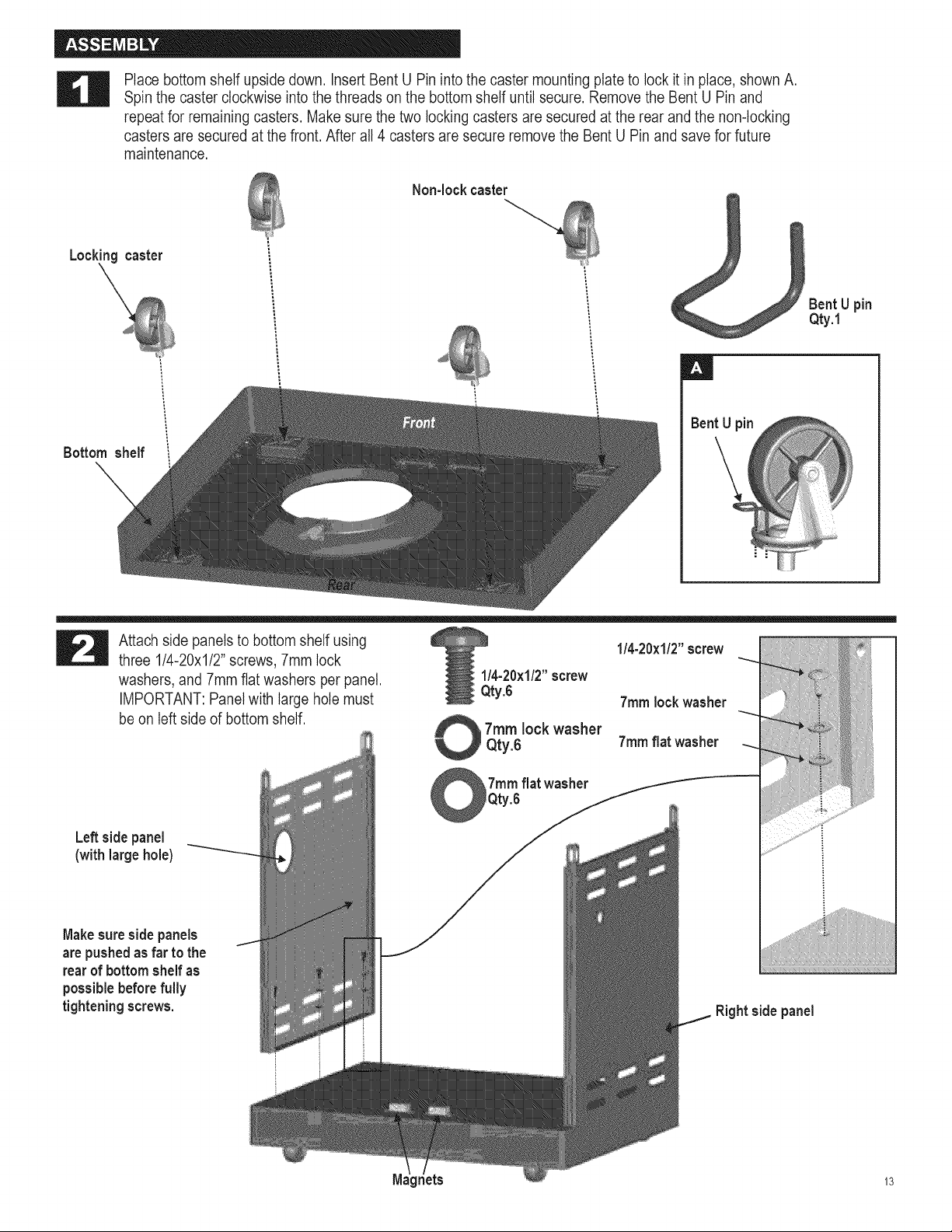
Place bottom shelf upside down. Insert Bent U Pin into the caster mounting plate to lock it in place, shown A.
Spin the caster clockwise into the threads on the bottom shelf until secure. Remove the Bent U Pin and
repeat for remaining casters. Make sure the two locking casters are secured at the rear and the non-locking
casters are secured at the front. After all 4 casters are secure remove the Bent U Pin and save for future
maintenance.
Non-lock caster
Lockingcaster
Bottom shelf !
Bent U pin
Qty.1
Bent U pin
Attach side panels to bottom shelf using
three 1/4-20xl/2" screws, 7mm lock
washers, and 7mm flat washers per panel.
IMPORTANT: Panelwith large hole must
be on left side of bottom shelf.
Leftsidepanel
(with large hole)
Makesuresidepanels
arepushedas far to the
rear of bottom shelfas
possiblebeforefully
tightening screws.
1/4-20×1/2"screw
Qty.6
7ram lock washer
Qty.6
7ram flat washer
Qty.6
1/4-20×1/2"screw
7ram lock washer
7ram flat washer
Right side panel
M _ts 13
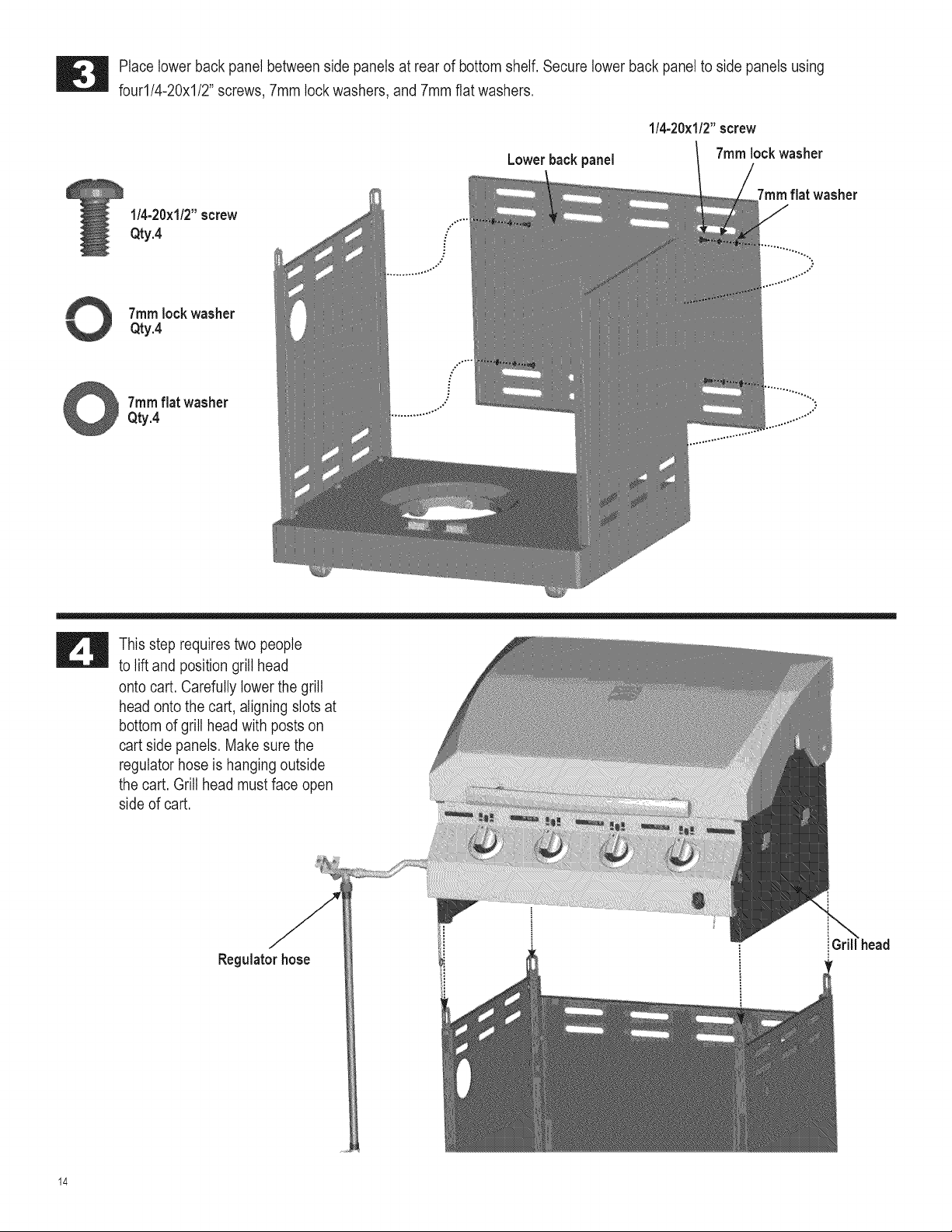
Place lower back panel between side panels at rear of bottom shelf. Secure lower back panel to side panels using
four1/4-20x1/2" screws, 7mm lock washers, and 7mm flat washers.
Lowerbackpanel
1/4-20×1/2"screw
7ram lock washer
1/4-20×1/2"screw
Qty.4 ..."
7ramflat washer
7ram lock washer
Qty.4
7ramflat washer ................
Qty.4 ......"
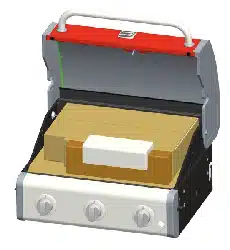
This step requires two people
to lift and position grill head
onto cart. Carefully lower the grill
head onto the cart, aligning slots at
bottom of grill head with posts on
cart side panels. Make sure the
regulator hose is hanging outside
the cart. Grill head must face open
side of cart.
Regulatorhose
14
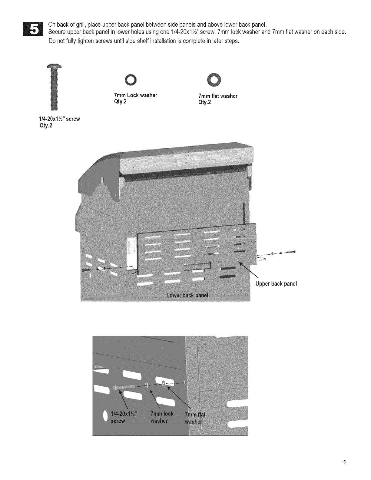
On back of grill, place upper back panel between side panels and above lower back panel.
Secure upper back panel in lower holes using one 1/4-20x1½" screw, 7mm lock washer and 7mm flat washer on each side.
Do not fully tighten screws until side shelf installation is complete in later steps.
7ramLockwasher 7ramflat washer
Qty.2 Qty.2
1/4-20×11/2"screw
Qty.2
Upperbackpanel
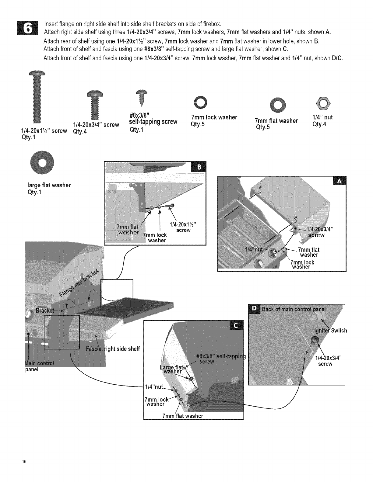
Insert flange on right side shelf into side shelf brackets on side of firebox.
Attach right side shelf using three 1/4-20x3/4" screws, 7turn lock washers, 7ram flat washers and 1/4" nuts, shown A.
Attach rear of shelf using one l/4-20xllA '' screw, 7ram lock washer and 7ram flat washer in lower hole, shown B.
Attach front of shelf and fascia using one #8x3/8" self-tapping screw and large flat washer, shown C.
Attach front of shelf and fascia using one 1/4-20x3/4" screw, 7ram lock washer, 7ram flat washer and 1/4" nut, shown D/C.
1/4-20×11/2"screw
Qty.1
@
large flat washer
Qty.1
#8×3/8" 7ram lock washer 1/4" nut
1/4-20×3/4" screw self-tapping screw Qty.5 7ram flat washer
Qty.4 Qty.1 Qty.5 Qty.4
l/4-20xlW'
screw
turn lock
washer
7ram flat
washer
'ram lock
washer
|
panel
washer
16
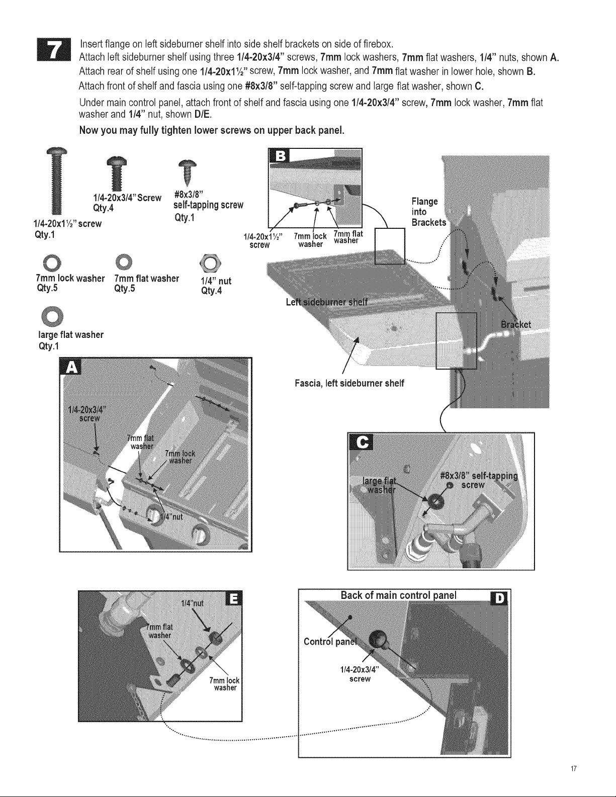
Insert flange on left sideburner shelf into side shelf brackets on side of firebox.
Attach left sideburner shelf using three 1/4-20x3/4" screws, 7ram lock washers, 7ram flat washers, 1/4" nuts, shown A.
Attach rear of shelf using one l/4-20xllA '' screw, 7ram lock washer, and 7ram flat washer in lower hole, shown B.
Attach front of shelf and fascia using one #8x3/8" self-tapping screw and large flat washer, shown C.
Under main control panel, attach front of shelf and fascia using one 1/4-20x3/4" screw, 7ram lock washer, 7ram flat
washer and 1/4" nut, shown DIE.
Now you may fully tighten lower screws on upper back panel.
l/4-20x3/4"Screw #8x3/8"
Qty.4 self-tappingscrew Flange
1/4-20x11/2"screw Qty.1 into
Qty.1 1/4-20x11/2"
screw
7ram lock washer 7ram flat washer 1/4" nut
Qty.5 Qty.5 Qty.4
largeflat washer
Qty.1
Fascia,left sideburnershelf
7mmlock
washer
Back of main control
1/4-20x3/4"
screw
17

IT!
First,removethe two screwsand lockwashers factory attachedto the sideburnervalve bracket.Positionsideburner
valvebracketbeneathsidebumershelffasciaso thatvalvestemcomesthroughlargercenterholeinfascia.Alignthe holes
onvalvebracketwithleftandrightholeson fascia. Secureusinglockwashersandscrewsthatwere removedfrom bracket.
Next,placesideburnerbezelovervalvestemonfront sideoffascia.Alignsmallholeson bezelwithupperandlowerholeson
fascia,makingsure "OFF"ison thetop.Attachusingtwo#8-32x3/8"screwsand4ram lockwashers.Presssidebumer
controlknob ontovalvestem.
Note: Use left and right
holes on fascia to
attach valve bracket
ScrewsandWashers
removedfrom valvebracket
Valvestem
Sideburner
valve bracket
b 8-32x3/8"screw
Qty.2
0 4ramlockwasher
Qty.2
Installbezelwith"OFF"attop.
Note:Use upperand lower
holeson fasciato attachbezel
Controlknob
#8-32x3/8"screw
Controlknobbeze
lockwasher _
D Pull out thefour knobs from controlpanel. Inserttemperaturegaugestem into the bigger hole aboveknob bezel,shownA.
Makesure the gauge is pushedin as far as it will go, then push the gauge downwarduntil it clips intothe panel, as shown
in B/C. Re-installthe knobs. Tem ire gauge stem
18
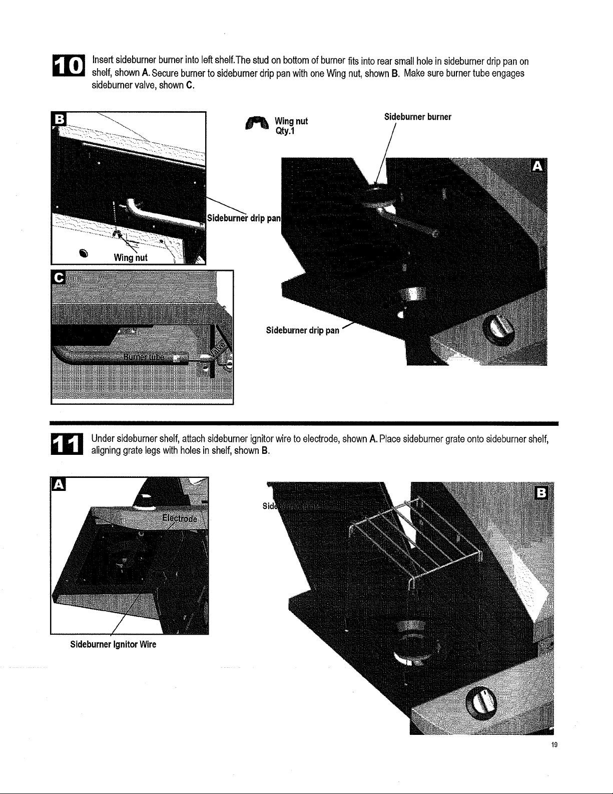
Insertsideburnerburnerinto left shelf.The stud on bottomof burner fits into rear smallholein sideburnerdrippanon
shelf,shownA. Secureburner to sideburnerdrip pan with one Wing nut,shownB. Makesure burnertube engages
sideburnervalve, shown C.
_1_ Wingnut
Qty.1
Sideburnerburner
drippan
Wingnut
Sideburnerdrippan
Undersideburnershelf,attach sideburnerignitorwire to electrode,shownA. Placesideburnergrate onto sideburnershelf,
aligninggrate legs with holesin shelf, shownB.
SideburnerIgnitorWire
19
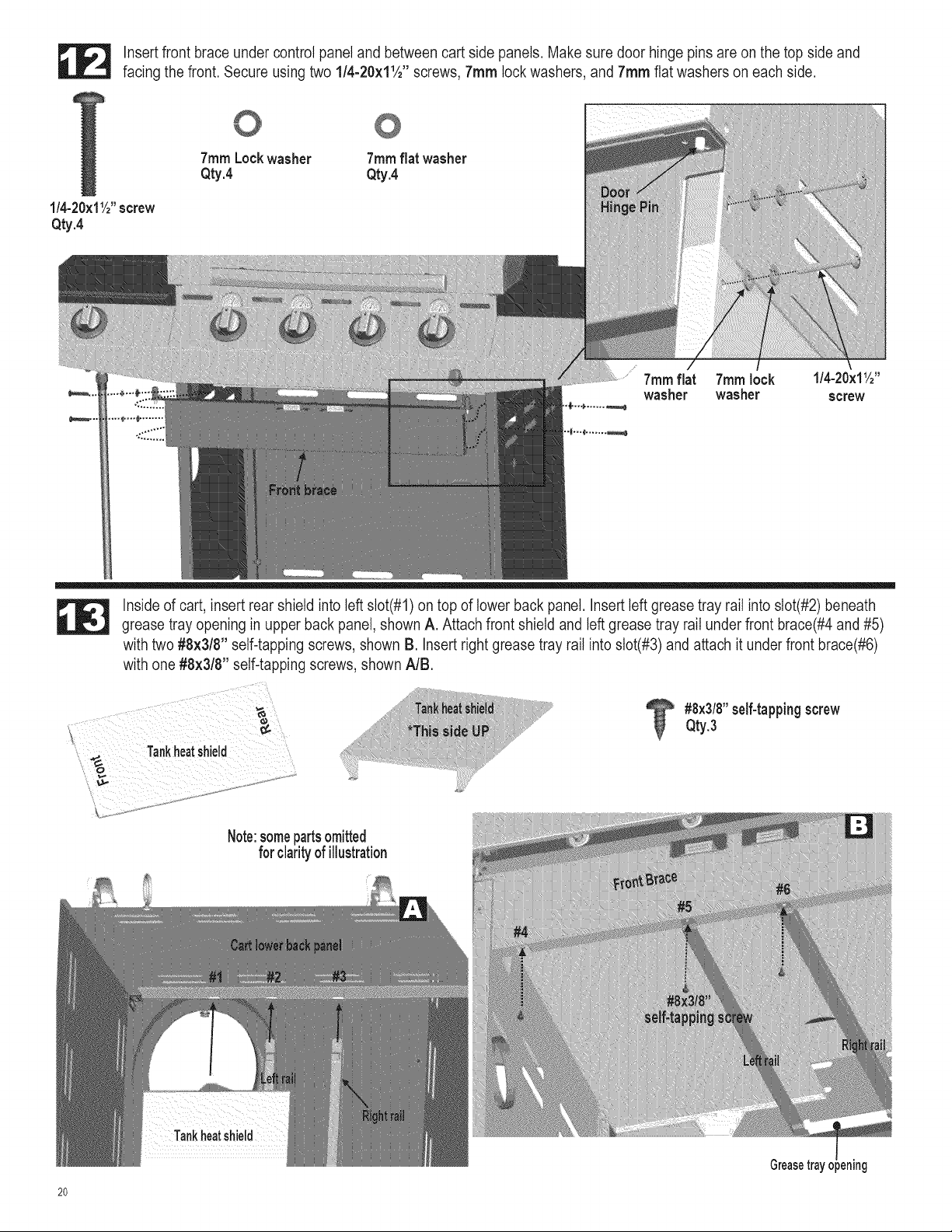
Insert front brace under control panel and between cart side panels. Make sure door hinge pins are on the top side and
facing the front. Secure using two l/4-20xllA '' screws, 7ram lock washers, and 7ram flat washers on each side.
7ram Lockwasher 7ram flat washer
Qty.4 Qty.4
1/4-20×11/2"screw
Qty.4
7ramflat 7ramlock 1/4-20×11/2''
washer washer screw
Inside of cart, insert rear shield into left slot(#1) on top of lower back panel. Insert left grease tray rail into slot(#2) beneath
grease tray opening in upper back panel, shown A. Attach front shield and left grease tray rail under front brace(#4 and #5)
with two #8x3/8" self-tapping screws, shown B. Insert right grease tray rail into slot(#3) and attach it under front brace(#6)
with one #8x3/8" self-tapping screws, shown NB.
#8x3/8"self-tappingscrew
Qty.3
Tankheatshield
Note:somepartsomitted
for clarityof illustration
20
Greasetrayopening
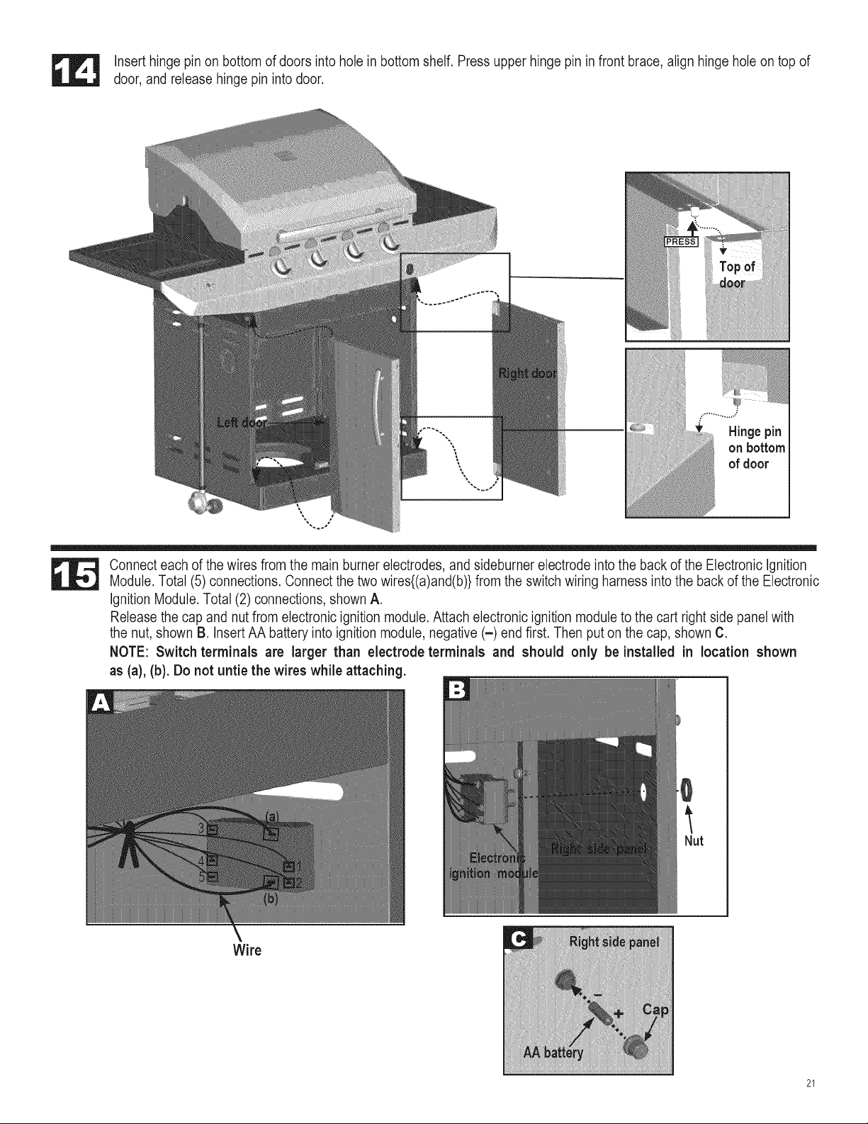
Insert hinge pin on bottom of doors into hole in bottom shelf. Press upper hinge pin in front brace, align hinge hole on top of
door, and release hinge pin into door.
Hinge pin
on bottom
of door
Connect each of the wires from the main burner electrodes, and sideburner electrode into the back of the Electronic Ignition
Module. Total (5) connections. Connect the two wires{(a)and(b)} from the switch wiring harness into the back of the Electronic
Ignition Module. Total (2) connections, shown A.
Release the cap and nut from electronic ignition module. Attach electronic ignition module to the cart right side panel with
the nut, shown B. Insert AA battery into ignition module, negative (-) end first. Then put on the cap, shown C.
NOTE: Switch terminals are larger than electrode terminals and should only be installed in location shown
as (a), (b). Do not untie the wires while attaching.
0
Nut
Wire
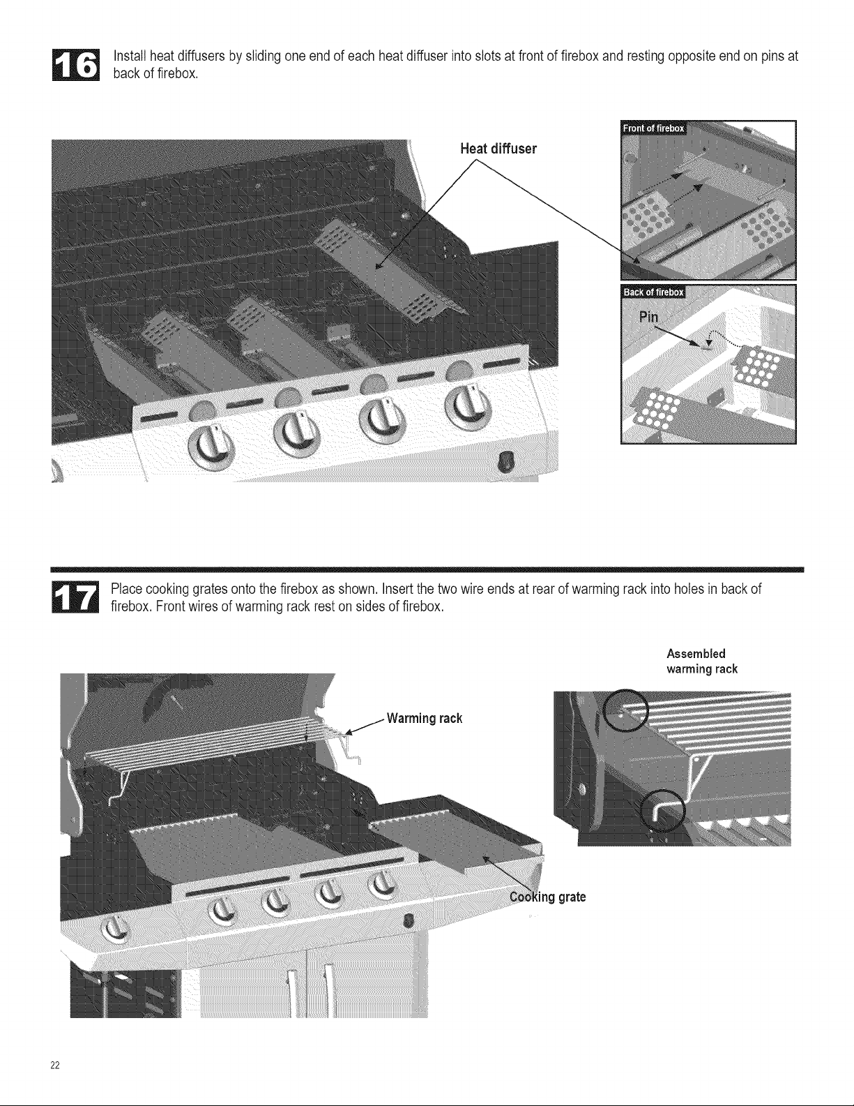
Installheatdiffusersbyslidingoneendofeachheatdiffuserintoslotsatfrontoffireboxandrestingoppositeendonpinsat
backoffirebox.
Heat diffuser
Place cooking grates onto the firebox as shown. Insert the two wire ends at rear of warming rack into holes in back of
firebox. Front wires of warming rack rest on sides of firebox.
Assembled
warming rack
rack
ing grate
22
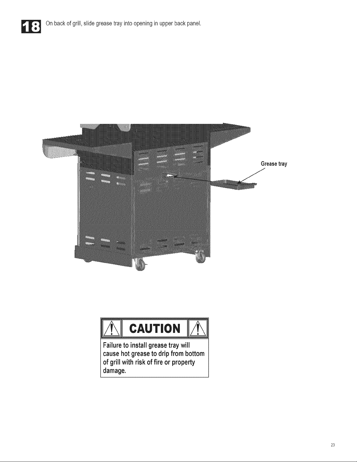
On back of grill, slide grease tray into opening in upper back panel.
Greasetray
m
Failureto installgreasetray will
causehotgreaseto drip from bottom
of grillwith risk of fire or property
damage.
23
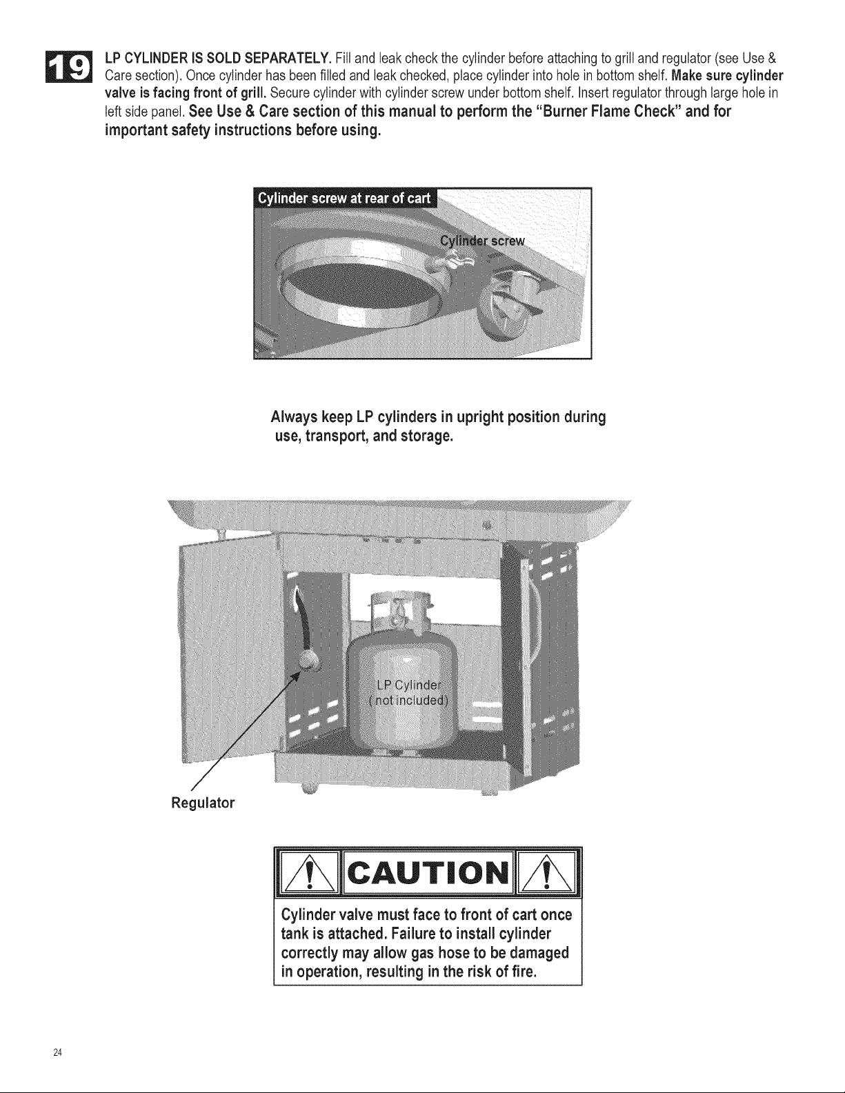
LP CYLINDER iS SOLD SEPARATELY. Fill and leak check the cylinder before attaching to grill and regulator (see Use &
Care section). Once cylinder has been filled and leak checked, place cylinder into hole in bottom shelf. Make sure cylinder
valve is facing front of grill. Secure cylinder with cylinder screw under bottom shelf. Insert regulator through large hole in
left side panel. See Use & Care section of this manual to perform the "Burner Flame Check" and for
important safety instructions before using.
Always keep LP cylinders in upright position during
use, transport, and storage.
Regulator
_ m
CAUT,o.
Cylinder valve must face to front of cart once
tank is attached. Failure to install cylinder
correctly may allow gas hose to be damaged
=noperation, resulting in the risk of fire.
24
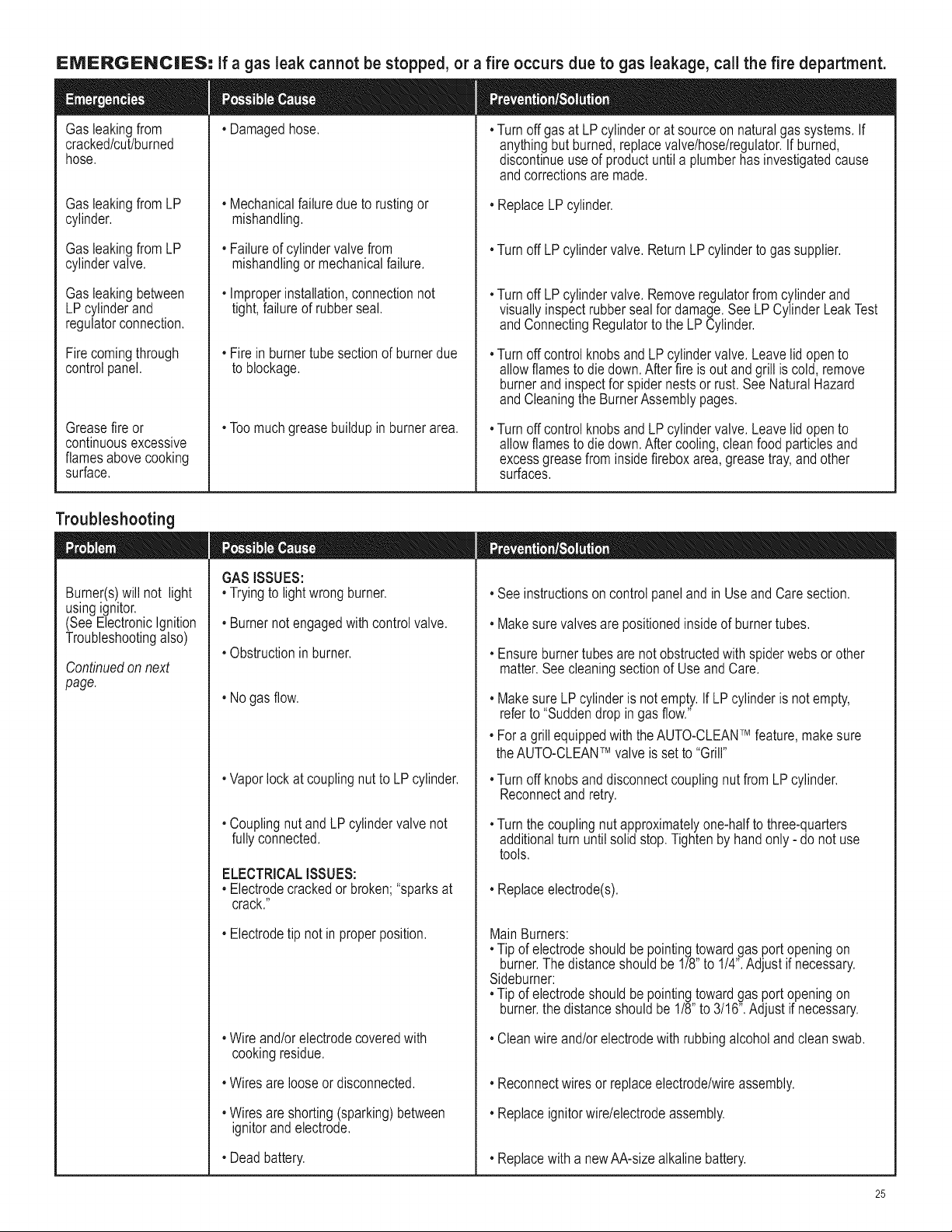
EIVlERGENCIIES= if a gas leak cannot be stopped, or a fire occurs due to gas leakage, call the fire department.
Gasleakingfrom
cracked/cut/burned
hose.
Gasleakingfrom LP
cylinder.
Gasleakingfrom LP
cylindervalve.
Gasleakingbetween
LPcylinderand
regulatorconnection.
Firecomingthrough
controlpanel.
Greasefire or
continuousexcessive
flamesabovecooking
surface.
, Damagedhose.
, Mechanicalfailuredue to rustingor
mishandling.
, Failureof cylindervalvefrom
mishandlingormechanicalfailure.
, Improperinstallation,connectionnot
tight,failureof rubberseal.
, Firein burnertube sectionof burnerdue
to blockage.
, Toomuchgreasebuildupin burnerarea.
, Turnoffgas at LP cylinderor at sourceon naturalgassystems.If
anythingbut burned,replacevalve/hose/regulator.If burned,
discontinueuseof productuntila plumberhas investigatedcause
andcorrectionsare made.
, ReplaceLP cylinder.
, Turnoff LP cylindervalve.ReturnLPcylinderto gassupplier.
, Turnoff LP cylindervalve.Removeregulatorfromcylinderand
visuallyinspectrubbersealfor damage.See LP CylinderLeakTest
andConnectingRegulatorto the LP Cylinder.
, TurnoffcontrolknobsandLPcylindervalve.Leavelidopento
allowflamesto diedown.Afterfire is outand grill is cold,remove
burnerandinspectfor spidernestsor rust.See NaturalHazard
andCleaningthe BurnerAssemblypages.
, TurnoffcontrolknobsandLPcylindervalve.Leavelidopento
allowflamesto diedown.Aftercooling,cleanfood particlesand
excessgreasefrom insidefireboxarea,greasetray,andother
surfaces.
Troubleshooting
Burner(s)will not light
usingignitor.
(SeeElectronicIgnition
Troubleshootingalso)
Continuedon next
page.
GASiSSUES:
, Tryingto lightwrongburner.
, Burnernot engagedwith controlvalve.
, Obstructioninburner.
, Nogas flow.
, Vaporlockat couplingnutto LP cylinder.
, Couplingnut andLPcylindervalve not
fullyconnected.
ELECTRICALISSUES:
, Electrodecrackedor broken;"sparksat
, Seeinstructionsoncontrolpanelandin UseandCaresection.
, Makesurevalvesare positionedinsideof burnertubes.
, Ensureburnertubesare not obstructedwith spiderwebsor other
matter.See cleaningsectionof UseandCare.
, MakesureLPcylinderis not empty.If LP cylinderis notempty,
referto "Suddendrop in gasflow."
, Fora grill equippedwith theAUTO-CLEANTM feature,makesure
theAUTO-CLEANTM valveis setto "Grill"
, Turnoff knobsand disconnectcouplingnut fromLPcylinder.
Reconnectandretry.
, Turnthe couplingnutapproximatelyone-halfto three-quarters
additionalturn untilsolidstop.Tightenby handonly- do not use
tools.
, Replaceelectrode(s).
crack."
, Electrodetip notin properposition.
, Wire and/orelectrodecoveredwith
cookingresidue.
, Wiresarelooseordisconnected.
, Wiresareshorting(sparking)between
ignitorandelectrode.
, Deadbattery.
MainBurners:
, Tip of electrodeshouldbepointingtowardgasport openingon
burner.The distanceshouldbe 118"to 114".Adjustif necessary.
Sideburner:
, Tip of electrodeshouldbepointingtowardgasport openingon
burner,the distanceshouldbe 118"to 3116".Adjustif necessary.
, Cleanwireand/orelectrodewithrubbingalcoholand cleanswab.
, Reconnectwiresor replaceelectrode/wireassembly.
, Replaceignitorwire/electrodeassembly.
, Replacewith a newAA-sizealkalinebattery.
25
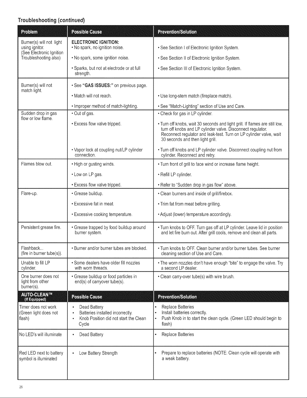
Troubleshooting(continued)
Burner(s)will not light
usingignitor.
(SeeElectronicIgnition
Troubleshootingalso)
Burner(s)will not
matchlight.
Suddendropin gas
floworlow flame.
Flamesblowout.
Flare-up.
ELECTRONICIGNITION:
• Nospark,noignitionnoise.
• Nospark,someignitionnoise.
, Sparks,but notat electrodeorat full
strength.
• See"GAS ISSUES:"onpreviouspage.
• Matchwill not reach.
• Impropermethodof match-lighting.
Unableto fill LP
cylinder.
Oneburnerdoes not
lightfromother
burner(s).
Timerdoesnot work
(Greenlightdoesnot
flash)
, Outof gas.
• Excessflow valvetripped.
•Vaporlockat couplingnut/LPcylinder
connection.
• Highorgustingwinds.
• LowonLPgas.
• Excessflow valvetripped.
• Greasebuildup.
• Excessivefat in meat.
• Excessivecookingtemperature.
• Greasetrappedby foodbuilduparound
burnersystem.
• SeeSectionI of ElectronicIgnitionSystem.
• SeeSectionII of ElectronicIgnitionSystem.
• SeeSectionIII of ElectronicIgnitionSystem.
, Uselong-stemmatch(fireplacematch).
• See"Match-Lighting"sectionof UseandCare.
• Checkfor gasin LPcylinder.
•Turnoff knobs,wait30secondsandlightgrill. Ifflamesarestilllow,
turnoff knobsand LP cylindervalve.Disconnectregulator.
Reconnectregulatorand leak-test.Turnon LP cylindervalve,wait
30secondsand thenlightgrill.
•Turnoff knobsandLPcylindervalve.Disconnectcouplingnutfrom
cylinder.Reconnectandretry.
•Turnfrontof grill to facewindor increaseflameheight.
• RefillLPcylinder.
• Referto "Suddendropin gasflow"above.
• Cleanburnersand insideof grilltfirebox.
•Trimfatfrommeatbeforegrilling.
•Adjust(lower)temperatureaccordingly.
•Turnknobsto OFF.Turngas off at LPcylinder.Leavelid in position
andlet fire burnout.After grill cools,removeandcleanall parts.
Persistentgreasefire.
Flashback... • Burnerand/orburnertubesare blocked. •Turnknobsto OFF.Cleanburnerand/orburnertubes.See burner
(firein burnertube(s)), cleaningsectionof Use and Care.
• Somedealershaveolderfill nozzles •The wornnozzlesdon'thaveenough"bite"to engagethe valve.Try
withworn threads, a secondLPdealer.
• Cleancarry-overtube(s)with wirebrush.
• Greasebuildupor foodparticlesin
end(s)of carryovertube(s).
• DeadBattery
• Batteriesinstalledincorrectly.
• Knob Positiondid notstart the Clean
Cycle
• ReplaceBatteries
• Installbatteriescorrectly.
• PushKnobin to startthe cleancycle.(GreenLEDshouldbeginto
flash)
No LED'swill illuminate • DeadBattery • ReplaceBatteries
• LowBatteryStrengthRedLED nextto battery
symbolis illuminated
• Prepareto replacebatteries(NOTE:Cleancyclewill operatewith
a weak battery.
26
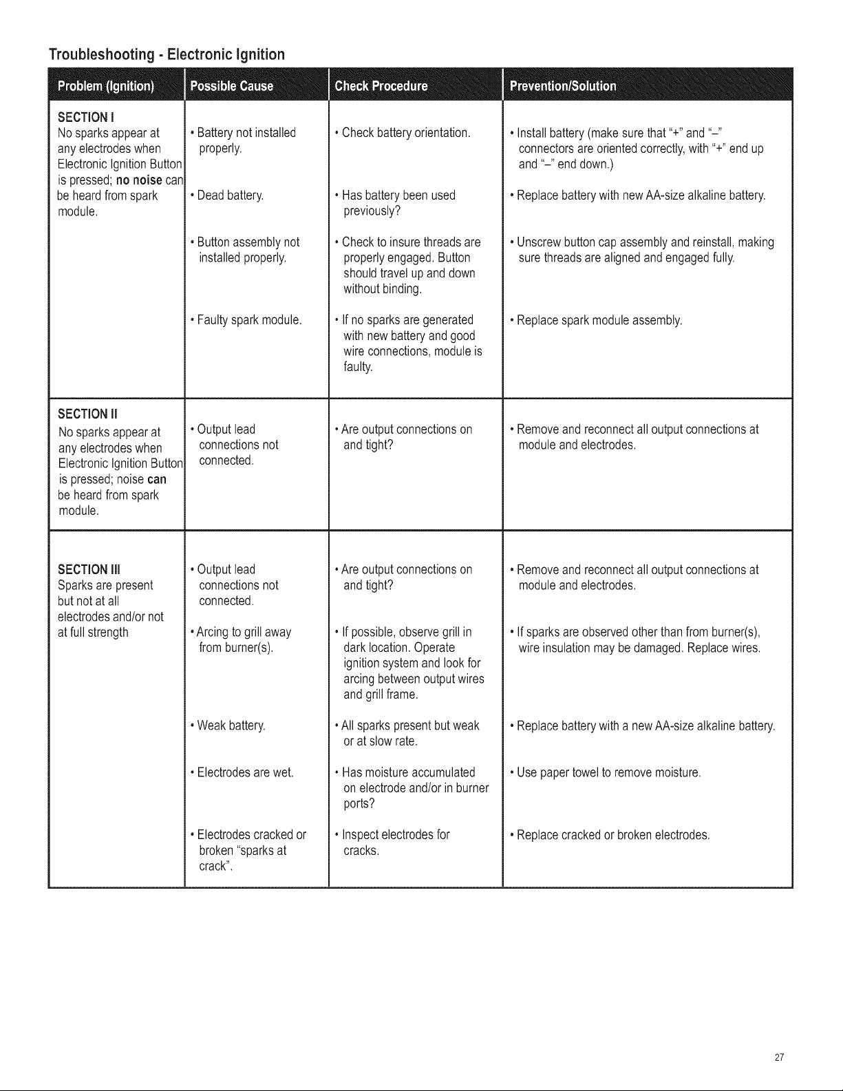
Troubleshooting - Electronic Ignition
• Batterynot installed
properly.
SECTIONI
Nosparksappearat
anyelectrodeswhen
ElectronicIgnitionButton
is pressed;no noise can
be heardfromspark
module.
SECTIONII
Nosparksappearat
any electrodeswhen
ElectronicIgnitionButton
is pressed;noisecan
beheardfromspark
module.
SECTIONill
Sparksare present
butnot at all
electrodesand/ornot
at fullstrength
, Checkbatteryorientation. • Installbattery(makesurethat "+"and"-"
connectorsare orientedcorrectly,with "+"endup
, Deadbattery. , Hasbatterybeenused
previously?
and"-" enddown.)
• Replacebatterywith newAA-sizealkalinebattery.
, Buttonassemblynot
installedproperly.
, Faultysparkmodule.
• Outputlead
connectionsnot
connected.
Checkto insurethreadsare
properlyengaged.Button
shouldtravelupanddown
withoutbinding.
If no sparksare generated
withnew batteryand good
wire connections,moduleis
faulty.
, Are outputconnectionson
andtight?
, Unscrewbuttoncap assemblyand reinstall,making
sure threadsarealignedandengagedfully.
, Replacespark moduleassembly.
, Removeandreconnectall outputconnectionsat
moduleandelectrodes.
• Outputlead
connectionsnot
connected.
, Arcingto grill away
fromburner(s).
, Weakbattery.
, Electrodesarewet.
, Electrodescrackedor
broken"sparksat
crack".
, Are outputconnectionson
andtight?
If possible,observegrillin
dark location.Operate
ignitionsystemandlookfor
arcingbetweenoutputwires
andgrillframe.
All sparkspresentbutweak
or at slow rate.
Hasmoistureaccumulated
on electrodeand/orin burner
ports?
Inspectelectrodesfor
cracks.
, Removeandreconnectall outputconnectionsat
moduleandelectrodes.
• If sparksareobservedotherthan fromburner(s),
wire insulationmaybedamaged.Replacewires.
, Replacebatterywitha newAA-sizealkalinebattery.
, Usepapertowelto removemoisture.
, Replacecrackedor brokenelectrodes.
27

28

29

30
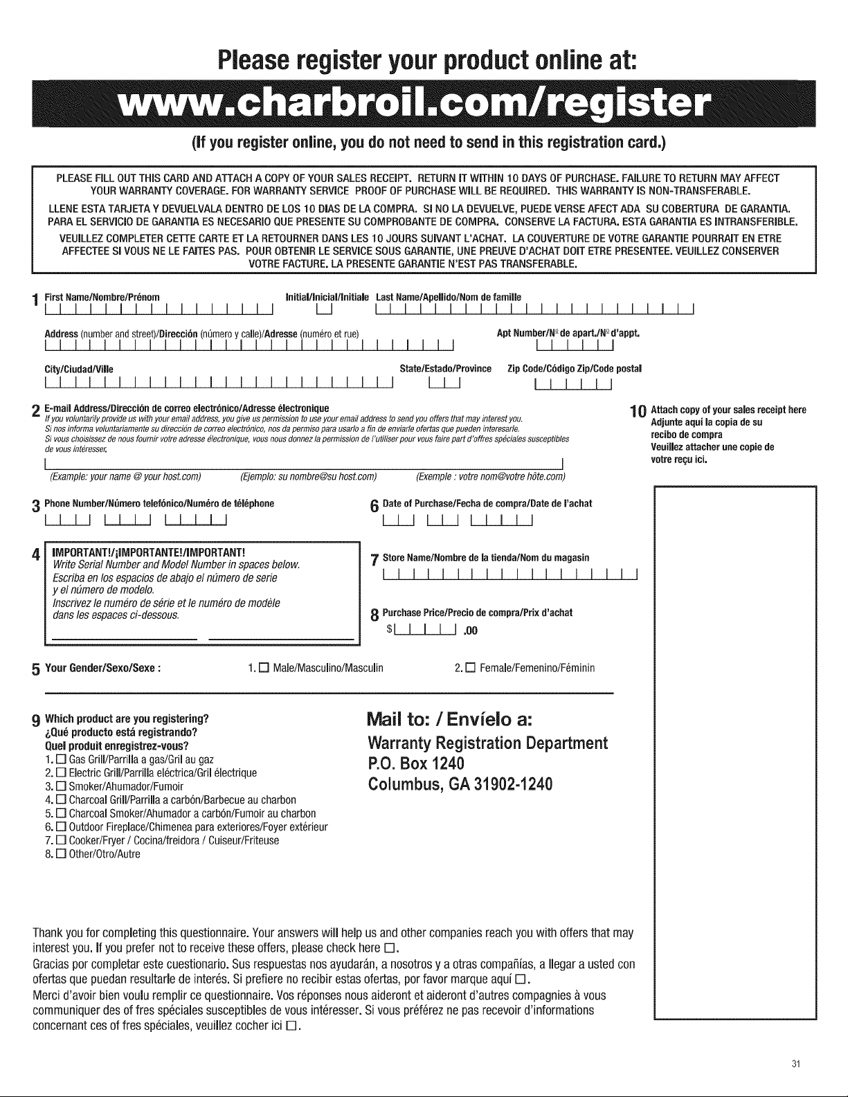
Pleaseregisteryourproductonline at:
(if you register online, you do not need to send in this registration card,)
PLEASEFiLL OUT THiS CARDAND ATTACH A COPYOF YOURSALES RECEIPT. RETURNiT WiTHiN t0 DAYS OF PURCHASE.FAILURETO RETURNMAYAFFECT
YOURWARRANTYCOVERAGE.FORWARRANTYSERVICE PROOFOF PURCHASEWiLL BE REQUIRED. THiS WARRANTYiS NON-TRANSFERABLE.
LLENE ESTATARJETAY DEVUELVALADENTRODE LOS 10 DIAS DE LACQMPRA. SI NO LADEVUELVE,PUEDEVERSEAFECTADA SU COBERTURA DE GARANTIA.
PARA EL SERVIClODE GARANTIAESNECESARIOQUE PRESENTESU COMPROBANTEDE COMPRA. CONSERVELA FACTURA.ESTA GARANTIAES INTRANSFERIBLE.
VEUILLEZCOMPLETERCETTECARTE ET LARETOURNERDANS LES 10 JOURS SUIVANT L'ACHAT. LA COUVERTUREDEVOTREGARANTIEPOURRAITEN ETRE
AFFECTEESI VOUS NE LE FAITESPAS. POUR OBTENIRLE SERVICESOUS GARANTIE, UNE PREUVED'ACHAT DOlT ETRE PRESENTEE.VEUILLEZCONSERVER
VOTRE FACTURE,LA PRESENTEGARANTIEN'EST PAS TRANSFERABLE,
1 FirstName/Nornbre/Pr6nom Initia|l|nicialllnitia|eLastNamelApellido/Nomdefamifle
I I I I I I I I I I I I I I I I L_J I I I I I I I I I I I I I I I I I I I I I I
Address(numberandstreet)/Direccibn(n0meroy calle)/Adresse(num6roet rue) AptNumber/N_deapart,INnd'appt,
I! II II II !! III!1 II !! II II III II II II II
City/Ciudad/Vi|le State/Estado/Pravince Zip Code/C6digaZip/Codepasta|
I ! I I I I I I I I I I ! I I I I I I I I ! ! I L_J_J I I I I I I
2 E=mailAddress/Direcci6ndecoffeeelectr6nice/Adresse61ectronique
If you voluntarily provide us with your email address, you give us permission to use your email address to send you offers that may interest you.
Sinos informa voluntariamente su direccion de coffee electr6nico, nos da permiso para usarlo a fin de enviarle ofertas qua pueden interesarle.
Si vous choisissez de nous fournir votre adresse e/ectronique, vous nous donnez la permission de I'utiliser pour vous faire part d'offres specialee susceptibles
de vous int_resser.
I I
(Example:yourname@yourhost.cam) (Ejemplo:su nombre@suhost.cam) (Example: votrenom@votrehSte.com)
3 PhoneNumber/N_meratelef6nico/Num6rede t61_phone 6 Dateof Purchase/Fechade compra/Datede I'achat
I I I I L___L__LJ_ I I I I I I I I I I I
IM PORTANT!/iIMPORTANTE!/IMPORTANT!
Write Serial Number and Model Number in spaces below.
Escriba en los espacios de abajo el nEsmerode serie
y el nEsmerode modelo.
Inscrivez le numero de s_rie et le num_ro de mod_le
dans los espaces ci-dessou&
7 Store Name/Nombrede la tienda/Norndu magasin
I I II I !! I I I II I ! !
8 PurchasePrice/Preciede compra/Prixd'achat
$1 I I I I .oo
I I
1 {} Attachcopyof yoursalesreceipthere
Adjunteaqui la capiadesu
recihedecornpra
VeuiHezattacher unecopiede
vatrerec;uici.
5 Your6ender/Sexo/Sexe:
1. [] Male/Masculino/Masculin 2. [] Female/Femenino/F_minin
9 Which product are you registering?
i,Qu_ producte est_ registrando?
Quel produit enregistrez-vous?
1. [] GasGdll/Parrilla a gas/Gril au gaz
2. [] Electric Grill/Parrilla el6ctrica/Gril 61ectrique
3. [] Smoker/Ahumador/Fumoir
4. [] Charcoal Grill/Parrilla a carb6n/Barbecue au charbon
5. [] Charcoal SmokeriAhumador a carb6n/Fumoir au charbon
6. [] Outdoor Fireplace/Chimenea para exteriores/Foyer ext6rieur
7. [] Cooker/Fryer/ CocinaJfreidora/ Cuiseur/Friteuee
8. [] OtheriOtro/Autre
Mail to: /Envielo a:
Warranty Registration Department
P.O.Box 1240
Columbus, GA 31902-1240
Thank you for completing this questionnaire. Youranswers will help us and other companies reach youwith offers that may
interest you. if you prefer not to receive these offers, please check here [].
Graciaspar completar este cuestionario. Sus respuestasnos ayudar&n,a nosotros y a otras compaSias, a Ilegar a usted con
ofertas que puedan resultade de inter6s. Si prefiere no recibir estas ofertas, par favor marque aqui [].
Merci d'avoir bienvoulu remplir ce questionnaire. Vos r@onses nous aideront et aideront d'autres compagnies _,vous
communiquer des of fres speciales susceptibles de vous int6resser. Si vous pr6f6rez ne pas recevoir d'informations
concernant ces of fres sp6ciales, veuillez cocher ici [].
31

Register your product :o receive a special offer
www.charbroil.com/registe
\
\
\
.,%
, ,,,,,,,,,,,,,,,,,,,,,,,,,,,,,,,.,,,,,,,,,,,,,,,,,,,,..........
_J
• Product information
• Grilling accessories
• Replacement parts
• Reliable customer
support
• Delicious recipes
• Grilling tips from
expert chefs
• Exciting events and
promotions
• Share your grilling
secrets
• Browse the on-line
store
• And much more!