Loading ...
Loading ...
Loading ...
12
© 2021 United States Stove Company
CONNECT GAS LINE
WARNING:
USE NEW BLACK IRON OR STEEL PIPE.
INTERNALLY TINNED COPPER OR COPPER
TUBING CAN BE USED PER NATIONAL FUEL
CODE, SECTION 2.6.3, PROVIDING GAS MEETS
HYDROGEN SULFIDE LIMITS, AND WHERE
PERMITTED BY LOCAL CODES. GAS PIPING
SYSTEM MUST BE SIZED TO PROVIDE MINIMUM
INLET PRESSURE (LISTED ON DATA PLATE) AT
THE MAXIMUM FLOW RATE (BTU/HR). UNDUE
PRESSURE LOSS WILL OCCUR IF THE PIPE IS
TOO SMALL.
A MANUAL SHUTOFF VALVE MUST BE
INSTALLED UPSTREAM OF THE APPLIANCE.
UNION TEE AND PLUGGED 1/8” NPT PRESSURE
TAPPING POINT SHOULD BE INSTALLED
UPSTREAM OF THE APPLIANCE. A SEDIMENT
TRAP SHOULD BE INSTALLED UPSTREAM TO
PREVENT MOISTURE AND CONTAMINANTS
FROM PASSING THROUGH THE PIPE TO
APPLIANCE CONTROLS AND BURNERS.
FAILURE TO DO SO COULD PREVENT THE
APPLIANCE FROM OPERATING RELIABLE.
NOTICE: A qualied gas appliance installer must
connect the heater to the gas supply. Consult all
local codes.
IMPORTANT: Hold heater valve rmly with a
wrench to prevent movement when connecting
to inlet pipe. Always use an external regulator for
all propane/LPG heaters and high pressure one to
two-pound systems only, to reduce the supply tank
pressure to a maximum of 13” w. This is in addition
to the internal regulator in the heater valve.
CHECK GAS TYPE: The gas supply must be the same
as stated on the heater’s rating plate. If the gas
supply is different, DO NOT INSTALL THE HEATER.
Contact your dealer for the correct model.
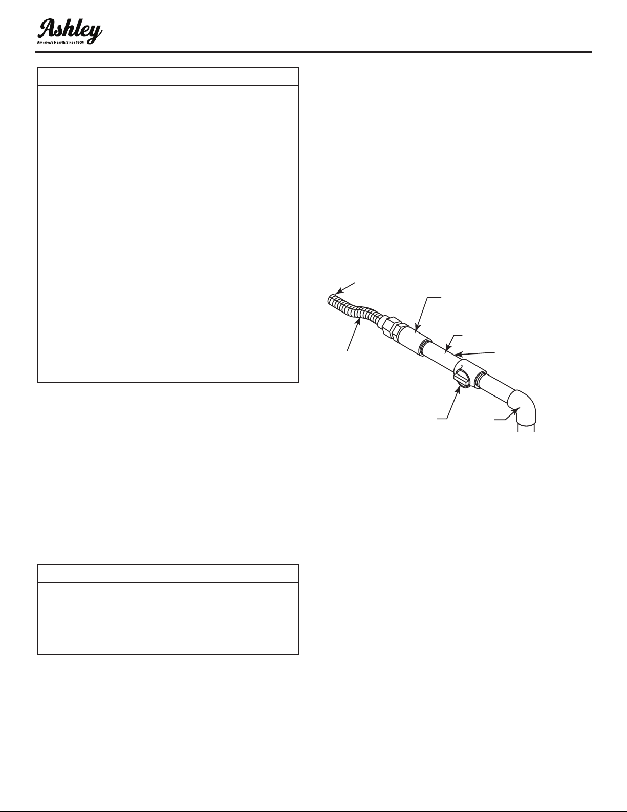
Pipe Coupling
To Heater
Valve
Gas
Supply
Inlet
Manual Shutoff Valve
Pipe
Stainless
Flexible
Tube
Locations that the
Pressure T
apping
Point May Be
Installed
ELECTRICAL WIRING (MILLIVOLT)
The millivolt valve is a self-powered combination
gas control THAT DOES NOT REQUIRE 110V AC TO
OPERATE.
CAUTION:
LABEL ALL WIRES PRIOR TO DISCONNECTION
WHEN SERVICING CONTROLS. WIRING ERRORS
CAN CAUSE IMPROPER AND DANGEROUS
OPERATION. VERIFY PROPER OPERATION
AFTER SERVICING.
CONNECT OPTIONAL WALL SWITCH
1. Use 18 AWG, two-wire cable, 15 feet maximum
length.
2. At one end of the cable, connect both wires to
the wall switch. At the other end, connect one
wire to TP/TH and one wire to TH, or connect the
wall switch to the two male (0.25”) terminals on
the left side of the unit.
CHECK SYSTEM OPERATION
The millivolt system and individual components
may be checked with a millivolt meter having a
0-1000 mV range. Conduct each check shown in
chart below by connection meter test leads to
terminals as indicated.
A. Complete Millivolt System Check (“A” Reading
- Thermostat contacts closed - Control Knob
“ON” - Main burner should turn on)
• If the reading is more than 100 millivolts and the
automatic valve still does not come on, replace
the control.
• If the closed circuit reading (“A” reading) is less
than 100 millivolts, determine cause for low
reading, proceed to section B below.
Loading ...
Loading ...
Loading ...