Loading ...
Loading ...
Loading ...
INSTALLATION – WATER HEATER
46
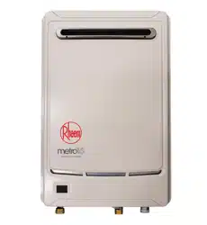
This water heater must be installed vertically upright with the
water, gas and power connections on the underside, pointing
toward the ground. The back of the water heater can be either
against a wall or supported by a frame.
Note: The water heater must be well secured to the wall or
frame using two fasteners each at the top and bottom of the
unit (refer to pages 54 and 55 for the
weight of the water heater
and
mounting hole positions). Use the screws provided only if
they are suitable for the wall or frame type. Otherwise select
and use alternative fasteners suitable for the application. The
fasteners must be capable of bearing the full weight of the
water heater so it may not work loose nor impose any load on
the gas and water pipe work connected to the water heater.
Refer to the fastener manufacturer’s information and
recommendations for the type of fastener to use for the wall or
frame type and load bearing requirements.
Alternatively the water heater can be recessed into a wall (refer to
“Recess Installation” on page 48).
For a single water heater installation, refer to the
typical installation diagram on page 58.
For a dual water heater installation using the EZ Link system, refer to
“EZ Link System Dual Installation” on
page 63 and the
typical installation diagram on page 67.
The water heater must not be installed in an area with a corrosive atmosphere where chemicals are stored or
where aerosol propellants are released. Remember the air may be safe to breathe, but when it goes through
a flame, chemical changes take place which may attack the water heater.
A secondary flue is not required. The water heater must not be installed indoors or in a confined space.
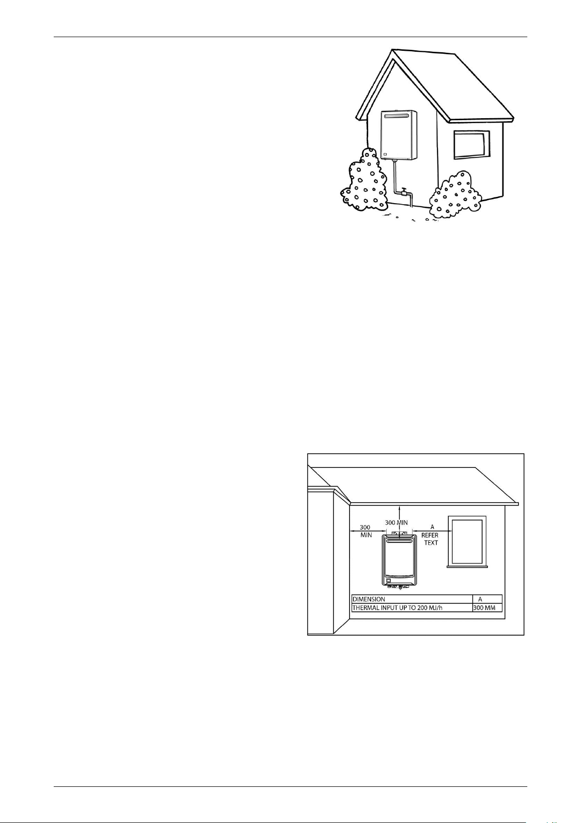
The water heater must be located to ensure that the location of the flue terminal complies with the requirements
of AS 5601 or AS/NZS 5601.1, as applicable under local regulations. As a guide the following requirements
are extracted from the Gas Installations Standard. The distances are measured along the wall behind the water
heater.
At least 300 mm between the top of the flue
terminal and the eaves.
At least 300 mm between the flue terminal and the
edge of any opening into the building, such as an
openable door or window, measured horizontally*.
At least 1500 mm between the top of the flue
terminal and the edge of any opening into the
building, such as an openable window, measured
vertically.
At least 300 mm between the flue terminal and a
return wall or external corner, measured
horizontally*.
At least 1500 mm between the flue terminal and
any opening into a building, in the direction of the
flue discharge.
At least 500 mm between the flue terminal and a fence, wall or other obstruction, in the direction of the
flue discharge.
Note: * If these horizontal distances cannot be achieved, AS/NZS 5601.1 states an equivalent horizontal
distance measured diagonally from the nearest discharge point of the flue terminal to the opening may be
deemed to comply. Check with the local regulator.
Loading ...
Loading ...
Loading ...