Loading ...
Loading ...
3
31-1000561 Rev. 2
This instruction provides for the installation of a Statement or Minimalist
handle collection on a ½” flush inset custom panel.
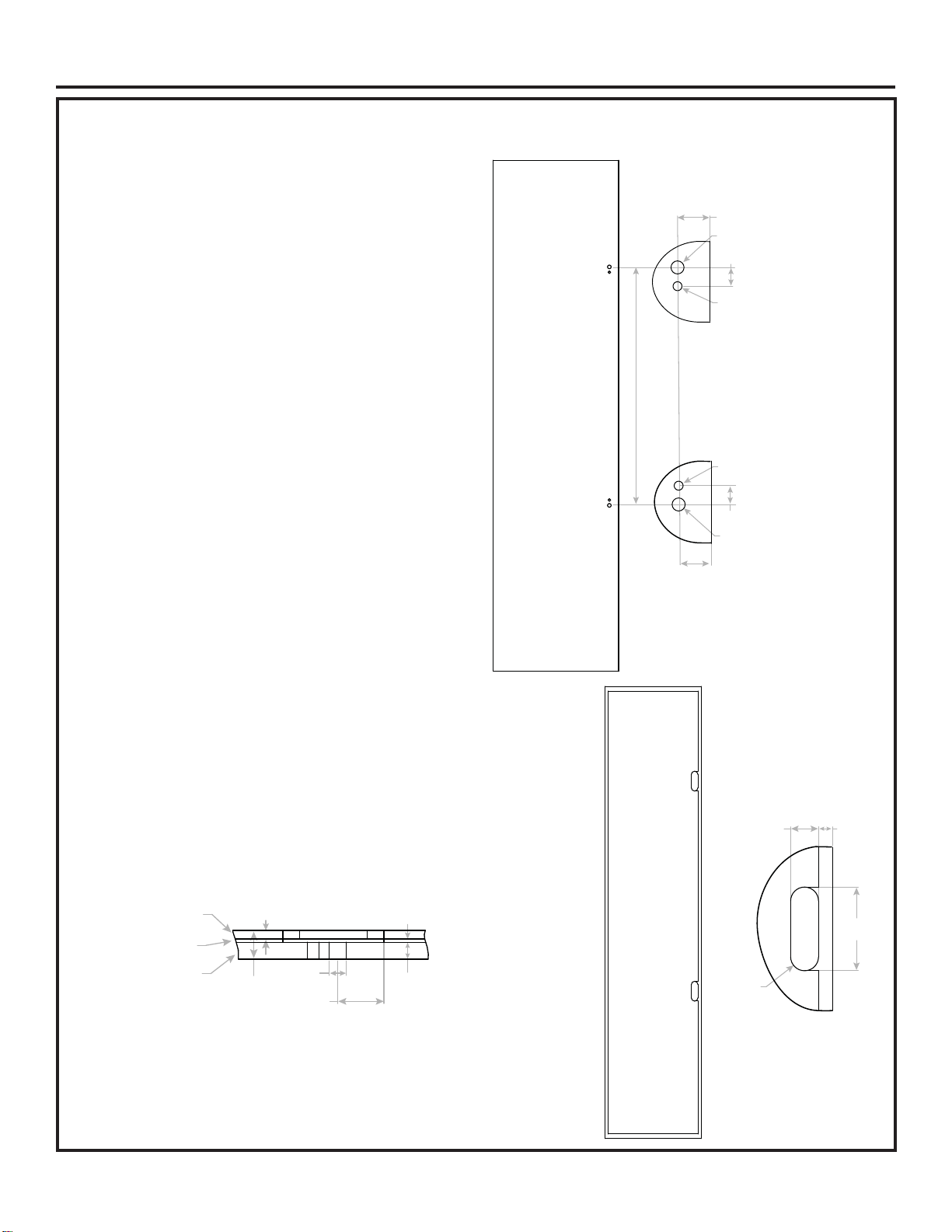
DRILL PILOT HOLES ON 1/2” PANEL
• Measure, mark and draw a line 1-1/4” (3.18 cm) from
the handle side edge, top to bottom.
• Please refer to Table 1 in page 1 for1/2” (1.27cm) holes
center to center distance (L)
• Center punch to mark hole locations.
• Drill 1/2” (1.27cm) pilot holes from the appearance side
and through the entire panel thickness.
• Drill 11/32” (0.87cm) pilot holes from the appearance
side and through the entire panel thickness. (On vertical
handle panels, drill hole 0.720” (1.83cm) below the 1/2”
(1.27cm) hole on top side of the door panel and 0.720”
(1.83cm) above the 1/2” (1.27cm) hole on bottom side
of the door panel. On Horizontal handle panels, drill
hole 0.720” (1.83cm) towards the center of the door
from 1/2” (1.27cm) hole.)
Routing Details for ¼” Backer Panel and 0.100”
Spacer
• Use a 1” (2.54cm) router bit to route on ¼” backer
panel and 0.100” spacer. See illustration
Hinge side
or Drawer Bottom
Handle side
View from
Nonappearance side
1"
(2.54cm)
3"
(7.62cm)
R1/2"
(1.27cm)
1/2"
(1.27cm)
1-1/4"
(3.18cm)
23/32"
(1.83cm)
11/32"
(0.87cm)
1/2"
(1.27cm)
23/32"
(1.83cm)
11/32"
(0.87cm)
1/2"
(1.27cm)
1-1/4"
(3.18cm)
center to center distance (L)
Hinge side
or Drawer Bottom
Handle side
View from
Nonappearance side
Detail Top Side
Detail Bottom Side
1/2"
(1.27cm)
1-3/8"
(3.49cm)
From the center of 1/2" hole
to the edge of the routing
.850"
(2.16cm)
.100"
(0.25cm)
1/2"
(1.27cm)
1/4"
(0.64cm)
1/4" Backer
Panel
0.100" Spacer
1/2" Panel
Installation Instructions
Loading ...
Loading ...
Loading ...