Loading ...
2
31-1000561 Rev. 2
Installation Instructions
This instruction provides for the installation of a Statement or Minimalist
handle collection on a 3/4” standard or flush inset custom panel.
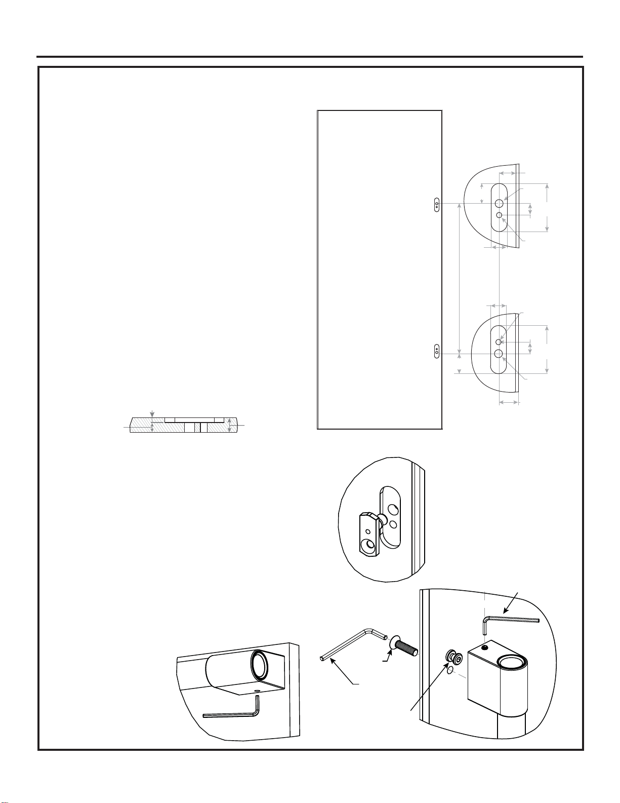
DRILL PILOT HOLES
• Measure, mark and draw a line 1-1/4” (3.18 cm) from
the handle side edge, top to bottom.
• Please refer to Table 1 in page 1 for1/2” (1.27cm) hole
center to center distance (L)
• Center punch to mark hole locations.
• Drill 1/2” (1.27cm) pilot holes from the appearance side
and through the entire panel thickness.
• Drill 11/32” (0.87cm) pilot holes from the appearance
side and through the entire panel thickness. (On
vertical handle panels, drill hole 0.720” (1.83cm) below
the 1/2” (1.27cm) hole on top side of the door panel
and 0.720” (1.83cm) above the 1/2” (1.27cm) hole on
bottom side of the door panel. On Horizontal handle
panels, drill hole 0.720” (1.83cm) towards the center of
the door from 1/2” (1.27cm) hole.)
• Use a 1” (2.54cm) router bit to route 1/4” (0.64 cm)
deep on a 3/4” (1.91 cm) panel. See illustration.
NOTE: The routing counter bore in the rear of the
decorative panel must ensure 1/2” (1.27 cm) material
thickness remains for handle support.
HANDLE ASSEMBLY
• Insert Handle Mounting Fastener assembly E from the
nonappearance side of the panel.
• Place the handle caps over the insert Handle Mounting
Fastener on the door. Take care to support the handle
so it doesn’t fall and scratch the appliance finish.
Make sure both handle caps are resting on the face
of the door.
• Lock one end of the handle into position by tightening the
countersunk screw D with the Allen wrench provided.
• Keep supporting the handle as you lock the other end of
the handle into position by tightening the countersunk
screw D.
• Finally tighten the set screw in the handle caps using the
Allen wrench provided in the handle kit. DO NOT over
tighten the set screw using a power tool.
NOTE: Set screw location
in end cap will vary by
model.
When installing horizontal
handles, position the handle
so that the set screws are
facing downward.
1-1/4"
(3.18cm)
1-1/4"
(3.18cm)
1/2"
(1.27cm)
11/32"
(0.87cm)
.720"
(1.83cm)
3"
(7.62cm)
1-1/4"
(3.18cm)
1"
(2.54cm)
.720"
(1.83cm)
3"
(7.62cm)
1-1/4"
(3.18cm)
1"
(2.54cm)
center to center distance (L)
1/2"
(1.27cm)
11/32"
(0.87cm)
Hinge side
or Drawer Bottom
Handle side
View from
Nonappearance side
Detail Top Side
Detail Bottom Side
1/4"
(0.64cm)
1/2"
(1.27cm)
3/4"
(1.91cm)
D
Allen wrench
provided in
the kit
Insert Assembly E
Allen Key provided
with handle kit
Tighten the set screw in the
handle cap after tightening
screw D
Loading ...
Loading ...
Loading ...