—
Do not store or use gasoline or other
flammable vapors and liquids in the
vicinity of this or any other appliance.
— WHAT TO DO IF YOU SMELL GAS
• Do not try to light any appliance.
•
Do not touch any electrical switch; do not
use any phone in your building.
• Immediately call your gas supplier from a
neighbor’s phone. Follow the gas
supplier’s instructions.
• If you cannot reach your gas supplier, call
the fire department.
—
Installation and service must be performed
by a qualified installer, service agency or
the gas supplier.
This appliance may be installed in an
aftermarket, permanently located,
manufactured home (USA only) or
mobile home, where not prohibited by
local codes.
This appliance is only for use with the type
of gas indicated on the rating plate. This
appliance is not convertible for use with
other gases, unless a certified kit is used.
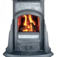
Mini Franklin Gas Stove
WARNING!:
FIRE OR EXPLOSION HAZARD
F
a
i
l
u
r
e
t
o
f
o
l
l
o
w
s
a
f
e
t
y
w
a
r
n
i
n
g
s
e
x
a
c
t
l
y
c
o
u
l
d
r
e
s
u
l
t
i
n
s
e
r
i
o
u
s
i
n
j
u
r
y
,
d
e
a
t
h
,
o
r
p
r
o
p
e
r
t
y
d
a
m
a
g
e
66 Airpark Road, West Lebanon, NH 03784 Tel: 800-866-4344
Rev6 (1809)
INSTALLER: Leave this manual with the
appliance.
CONSUMER: Retain this manual for future
reference.
TESTED AND LISTED BY
A barrier designed to reduce the risk of burns
from the hot viewing glass is provided with this
appliance and shall be installed for the protection
of children and other at-risk individuals.
DANGER!
p
!
HOT GLASS WILL
CAUSE BURNS.
DO NOT TOUCH GLASS
UNTIL COOLED.
NEVER ALLOW CHILDREN
TO TOUCH GLASS.
Model 208
CERTIFIED TO AMERICAN NATIONAL
STANDARD Z21.88-2017
AND APPLICABLE PORTIONS OF UL307b
p
!
OWNER’S MANUAL

SAFETY PRECAUTIONS
u This appliance is only for use with the type of gas
indicated on the rating plate. This appliance may not be
converted to use with other gasses unless a certified kit is used.
u This appliance is designed to burn either natural gas or
propane. Do not attempt to burn wood, trash, or any other
material in this appliance.
u This appliance may not be connected to a chimney
serving a separate solid fuel-burning appliance.
_____________________________________________________
u Due to high temperatures, the appliance should be
located out of traffic and away from furniture and draperies.
u Children and adults should be alerted to the hazards of
high surface temperature and should stay away to avoid burns
or clothing ignition.
u Young children should be carefully supervised when
they are in the same room as the appliance. Toddlers, young
children, and others may be susceptible to accidental contact
burns. A physical barrier is recommended if there are at-risk
individuals in the house. To restrict access to a fireplace or
stove, install an adjustable safety gate to keep toddlers, young
children, and other at-risk individuals out of the room and
away from hot surfaces.
u Clothing or other flammable material should not be
placed on or near the appliance.
u The appliance area must be kept clear and free from
combustible materials, gasoline, and other flammable vapors
and liquids.
u WARNING! Do not operate appliance with the glass
front removed, cracked or broken. Replacement of the glass
should be done by a licensed or qualified service person.
u The flow of combustion and ventilation air must not be
obstructed.
_____________________________________________________
u Any safety screen or guard removed for servicing an
appliance should be replaced prior to operating the appliance.
u Do not use this appliance if any part has been under
water. Immediately call a qualified service technician to inspect
the appliance and to replace any part of the control system and
gas control which has been under water.
u CAUTION! Label all wires prior to disconnection
when servicing controls. Wiring errors can cause improper and
dangerous operation.
u Verify proper operation after servicing.
NOTICE! The installation of the
Mini
Franklin
Gas Stove must conform with local codes, or in the
absence of local codes, with the National Fuel Gas
Code, ANSI Z233.1/NFPA 54.
The Mini Franklin Gas Stove must be vented
with approved “direct-vent” pipe. Direct-Vent pipe
has two concentric passageways which draw outside
air in for combustion, and let exhaust gasses out.
Installation or replacement of gas piping,
the gas stove, and repair or servicing of equipment
shall be performed only by a qualified agency. The
term “qualified agency” means any individual, firm,
corporation, or company that either in person or
through a representative is engaged in and is
responsible for (a) installation or replacement of gas
piping or (b) the connection, installation,
repair or servicing of gas utilization equipment, who
is experienced in such work, familiar
with all precautions required, and has complied with
all the requirements of the authority having
jurisdiction.
Installation and repair should be done by a
qualified service person. The appliance should be
inspected before use and at least annually by a
professional service person. More frequent
cleaning may be required due to excessive lint
from carpeting, bedding material, et cetera. It is
imperative that control compartments, burners
and circulating air passageways of the appliance
be kept clean.
The Mini Franklin Gas Stove and its main gas
supply valve must be disconnected from the gas
supply piping system during any pressure testing of
that system at test pressures in excess of 1/2 psi (3.5
kPa).
The Mini Franklin Gas Stove must be isolated
from the gas supply piping system by closing its
equipment shutoff valve during any pressure testing
of the gas supply piping system at test pressures
equal to or less than 1/2 psi (3.5 kPa).
An inlet pressure test point is provided on the gas
control valve, immediately upstream of the gas
supply connection to the Fireplace. An outlet
pressure test point is also provided.
The Mini Franklin Gas Stove, when installed in a
mobile home, must be electrically grounded in
accordance with local codes or, in the absence of
local codes, with the National Electrical Code,
ANSI/NFPA 70.
A barrier designed to reduce the risk of
burns from the hot viewing glass is
provided with this appliance and shall be
installed for the protection of children
and other individuals at risk.

First, thank you from all of us at Woodstock Soapstone Co. for installing this
Franklin Fireplace for one of our customers. If you have any questions about
installation, please call us at 800-866-4344. Technical Support will be available
from 9:00AM to 5:00PM Eastern Time, Monday through Saturday. At any other
time, you may leave a message with our answering service with your phone
number and the best time to call, and we will return your call during the next
business day.
Please also take the time to go through the Warranty Checklist with the
owner. This will validate the warranty, assure us and the owner that the
installation was performed to local and national codes, and help familiarize the
owner with the safe operation of this gas Fireplace.
Installation must conform to these instructions and local codes
or, in the absence of local codes, with the current National Fuel Gas Code
ANSI Z233.1.
We at Woodstock Soapstone Company are proud to manufacture top
quality hearth products. When you install this Fireplace, we ask that you
maintain our tradition of conscientious effort to make our customers happy
with our product and service.
-------------------------------------------------------------------------------------------------------------------------------------------------------------------------------------------------------- 1
-------------------------------------------------------------------------------------------------------------------------------------------------------------------------- Table Of Contents
QUESTIONS:
800-866-4344
9:00 AM to 5:00 PM
Eastern Time
WARNING: This unit
must be installed by a
qualified gas technician in
accordance with local codes
or in the absence of local
codes, with the most current
edition of the National Fuel
Gas Code ANSI
Z223.1/NFPA 54.
TO THE INSTALLING TECHNICIAN:
TABLE OF CONTENTS
Section Page
1) Code Approvals..........................................................2
2) Specifications.............................................................2
3) Tools Needed to Install the Fireplace........................3
4) Approved Venting/Chimney Materials .....................3
5) Approved Clearances for Inside Locations...............4
6) Approved Venting/Chimney Configurations ...........6
7) Approved Venting/Chimney Terminal Clearances .10
8) Assembling the Mini Franklin Gas Fireplace.........11
9) Pre-Installation Inspection Checklist ......................12
10) Connecting the Gas Supply/Testing the Flame.......12
11) Air Shutter Adjustment / Screen Barrier............13-14
12) Testing Check List and Warranty Registration........ (insert)
Section Page
13) Troubleshooting - Installer only............................16
14) Operating your Gas Fireplace...............................17
15) Lighting Instructions.............................................18
16) Safety Instructions ................................................21
17) Remote Control.....................................................22
18) Lighting the Fire for Remote Control Owners.....24
19) Routine Maintenance ............................................25
20) Annual Inspection .................................................27
21) Troubleshooting - Owner......................................28
22) Warranty ................................................................30
Appendix A - Parts List...............................................31
Appendix B - Remote Control Installation ................33
SAFETY ALERT INDEX
• DANGER! INDICATES A HAZARDOUS SITUATION WHICH, IF NOT AVOIDED WILL RESULT IN DEATH OR SERIOUS INJURY.
• WARNING! INDICATES A HAZARDOUS SITUATION WHICH, IF NOT AVOIDED COULD RESULT IN DEATH OR SERIOUS INJURY.
• CAUTION! INDICATES A HAZARDOUS SITUATION WHICH, IF NOT AVOIDED, COULD RESULT IN MINOR OR MODERATE INJURY.
• NOTICE: USED TO ADDRESS PRACTICES NOT RELATED TO PERSONAL INJURY.
p
!
The Woodstock
Mini
Franklin Gas Stove is listed as a direct vent appliance.
This type of appliance draws all of its air for combustion from outside of
the dwelling through specially designed pipe. It can be used with natural
gas or LPG (liquid propane gas).
Approved to: American National Standard Z21.88-2017
For The Woodstock
Mini
Franklin Gas Stove:
Fuel .......................................................Liquefied Petroleum Gas (LPG)
..............................................................................Natural Gas (NG)
Manifold Pressure, LPG ...........................................................10.5" w.c.
Manifold Pressure, NG. .............................................................3.5" w.c.
Minimum inlet supply pressure for input
adjustment LPG................................................................11.0" w.c.
Minimum inlet supply pressure for input
adjustment NG ...................................................................4.0" w.c.
Maximum inlet supply pressure LPG......................................14.0" w.c.
Maximum inlet supply pressure NG .......................................14.0" w.c.
Input, Btu/Hr LPG Max. .........................................................8,349
(0 – 2,000 ft.) Min. ...........................................................6,677
NG Max. .......................................................10,201
Min. ..........................................................7,349
Output, Btu/Hr LPG Max. ..........................................................5,458
Min. ..........................................................4,435
NG Max. .........................................................6,648
Min. ......................................................... 4,654
Orifice size, LPG
Sea level to 3000' .......................................................#66 (0.0330)
3001' to 6000' ........................................................#68 (0.0310)
6001' to 9000' ........................................................#70 (0.0280)
Orifice size: NG
Sea level to 2000' ........................................................#53 (0.0595)
2001' to 5000' ........................................................#54 (0.0550)
5001' to 9000' ........................................................#55 (0.0520)
AFUE: (Annual Fuel Utilization Efficiency)LPG ..........(77% minimum)
AFUE: (Annual Fuel Utilization Efficiency)NG ............(72% minimum)
Glass Panel..............................................High temperature ceramic glass
Weight, Fireplace only ....................................................................75 lbs.
shipping..............................................................................88 lbs.
Ignition.................................................Standing pilot with Piezo ignition
-------------------------------------------------------------------------------------------------------------------------------------------------------------------------------------------------------- 2
--------------------------------------------------------------------------------------------------------------------------------------------------------------------------------- Specifications
1. CODE APPROVALS • Direct Vent • Natural Gas • LPG
2. SPECIFICATIONS
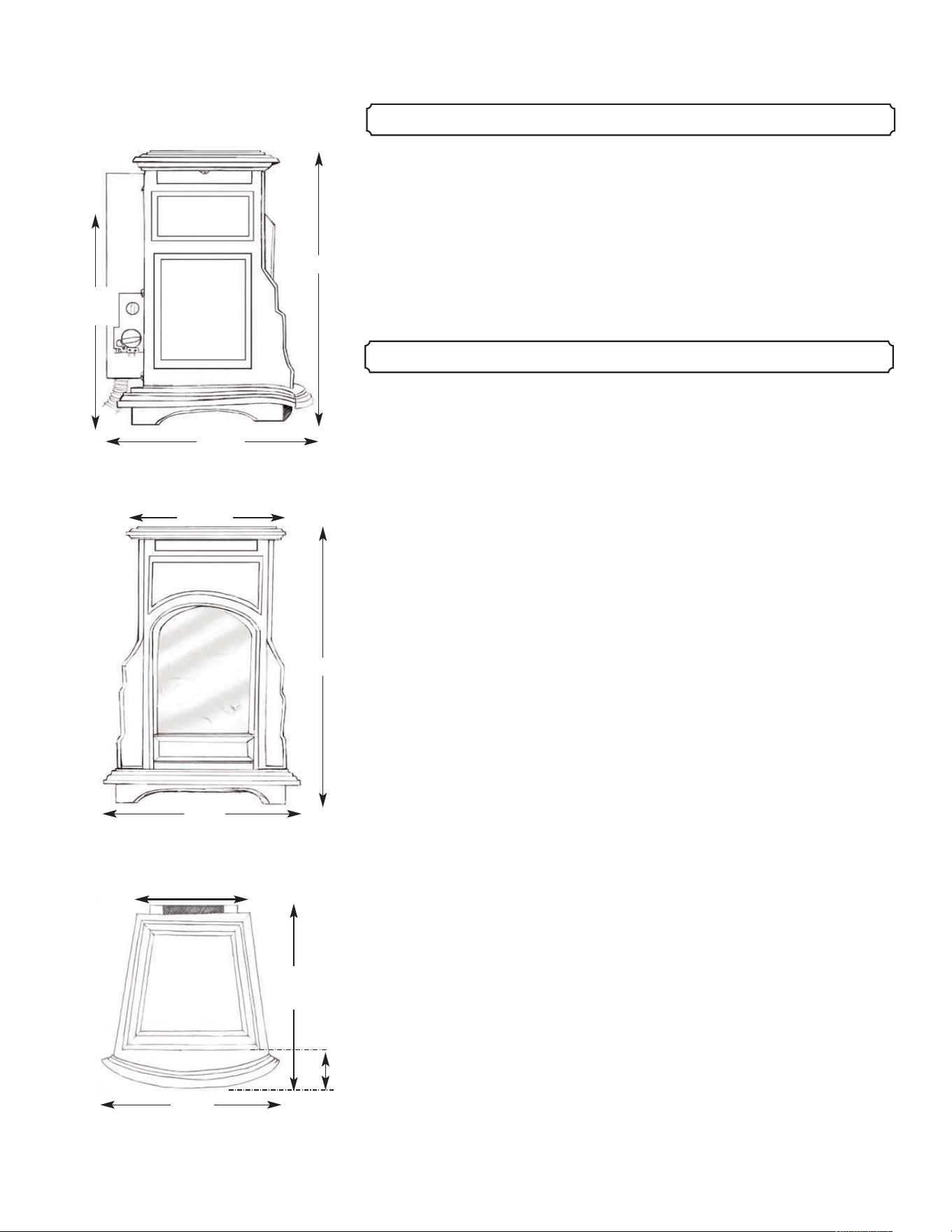
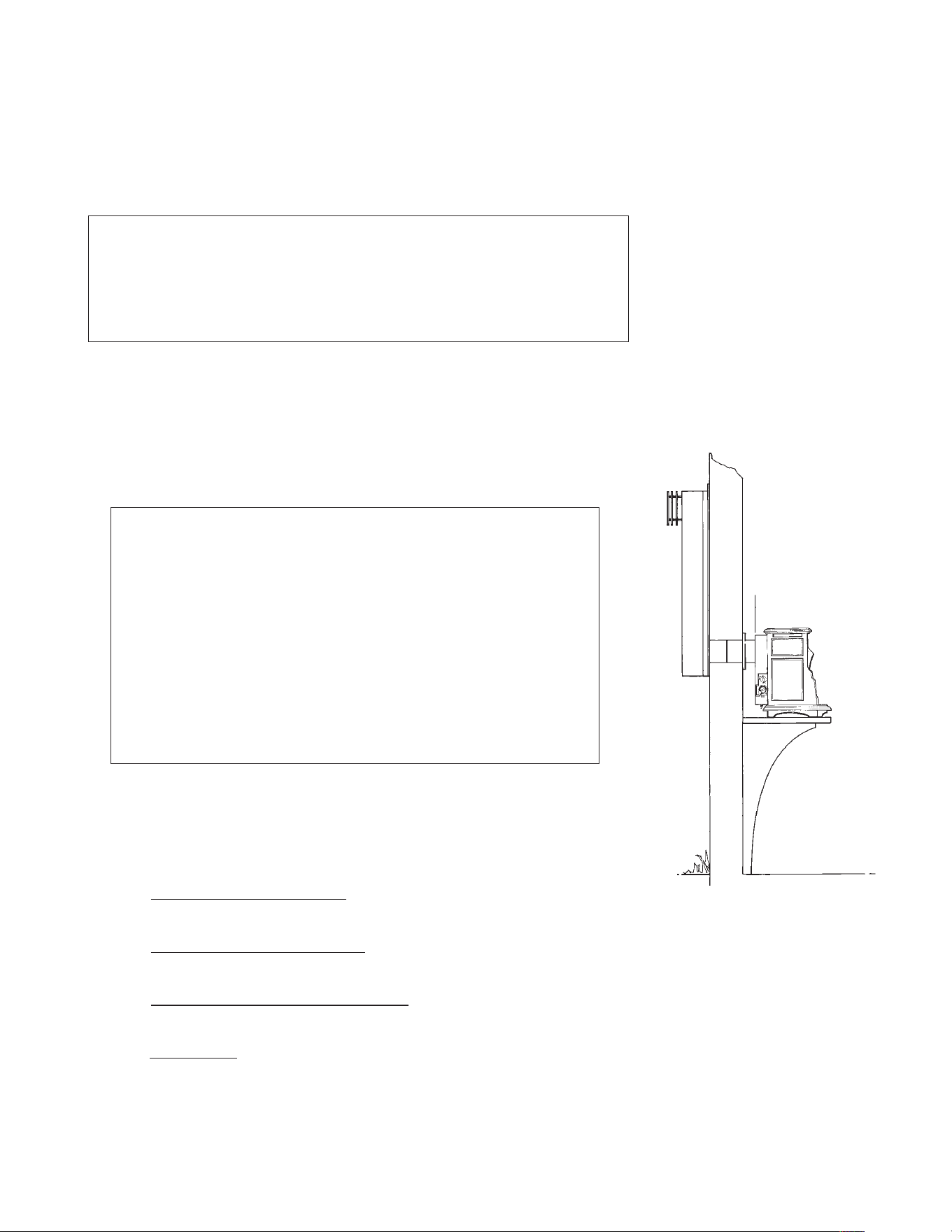
Illustration 2.1 Side View.
Illustration 2.2 Front View.
Illustration 2.3 Top View.
17"
17"
14
1
/
2
"
14
1
/
2
"
14
1
/
2
"
14
1
/
2
"
3
3
/
4
"
8
3
/
4
"
11
1
/
8
"
13
1
/
2"
Hearth: The hearth immediately under the Stove should be constructed of
non-combustible material - ceramic tile (not vinyl), stone, or metal. Protect
wood, carpet or any combustible surface with a hearth that covers an area
equal to the full width and depth of the Stove (14
1
/
2
" x 14
1
/
2
") or greater.
A hearth pad of size 16 x 16 inch is recommended
Clearance to combustible materials
Front of Firebox .............................................................................20"
Sides of Stove...................................................................................2"
Rear of Stove ....................................................................................2"
Rear Corners of Stove ...................................................................1.5"
Rear of 90 Degree Elbow.................................................................3"
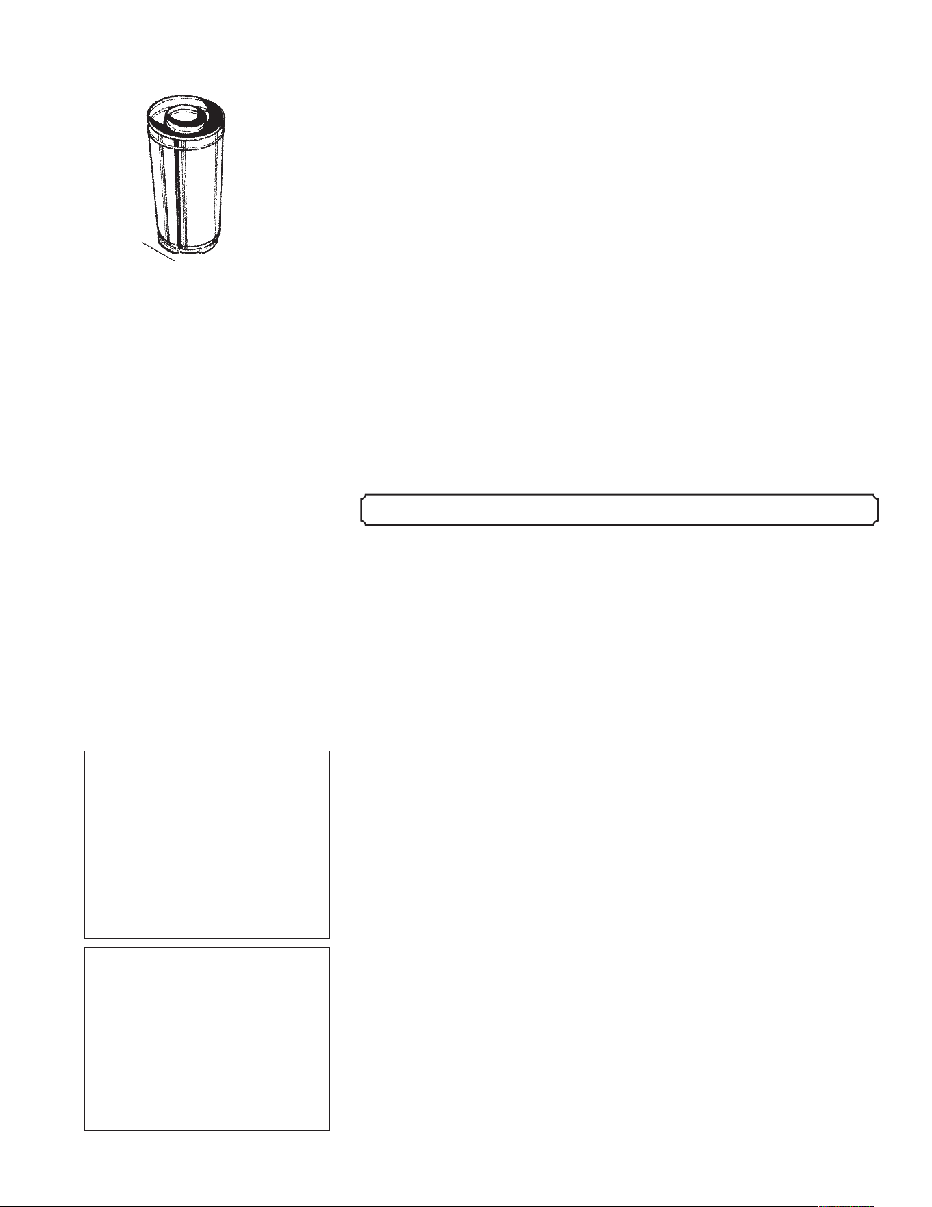
The venting/chimney system for your Mini Franklin Gas Stove must be
constructed of Simpson Dura-Vent 3” x 4
5
/8” direct vent gas pipe. Direct
vent pipe brings fresh air into the stove and vents exhaust gasses at the
same time (see illustration 4.1). The Mini Franklin Gas Stove must be
installed with this pipe to conform to safety requirements. The Mini
Franklin Gas Stove may not be connected to a flue serving any other
appliance.
Approved venting materials are available only from Woodstock
Soapstone Company. No other manufacturer makes a residential gas stove
of this size, so the pipe is unique to the Mini Franklin Gas Stove. Approved
components are listed below.
Description Dura-Vent No.
Standard Direct Vent Kit consists of:
1 4
5
/8" x 9” S traight P ipe 34 GSS-0 9
1 4
5
/8" Wall Thimble 34 GSS-3 14 3I
1 4
5
/8" Wall Thimble C over 34 GSS-3 14 3O
1 4
5
/8" Sno rkel Termina ti on 34GSS-SNK30
Other Available Pipe:
4
5
/8" x 6" Straight Pipe 34GSS-06B
4
5
/8" x 9" Straight Pipe 34GSS-09B
4
5
/8" x 12" Straight Pipe 34GSS-12B
-------------------------------------------------------------------------------------------------------------------------------------------------------------------------------------------------------- 3
------------------------------------------------------------------------------------------------------------------------------------ Installation Tools and Materials Needed
3. TOOLS NEEDED TO INSTALL THE FIREPLACE
4. APPROVED VENTING/CHIMNEY MATERIALS
EXHAUST OUT
AIR IN
AIR IN
Multi-meter ( millivolt )
Strap Wrench for Pipe Installation
Manometer
Gas Sniffer
Phillips Screwdriver
Glass Cleaner and Towels
Flashlight
Drill/Driver to install screws in first section of vent pipe
5/32” Allen Wrench*
* To install and adjust leveling screws in stove base
Illustration 4.1 Direct-vent pipe
sends exhaust out and brings air in
at the same time.
4
5
/8" x 24" Straight Pipe 34GSS-24B
4
5
/8" x 36" Straight Pipe 34GSS-36B
4
5
/8" x 48" Straight Pipe 34GSS-48B
4
5
/8" x 11"- 14-5/8" Adjustable Pipe 34GSS-1114B
4
5
/8" x 17 - 24" Adjustable Pipe 34GSS-1724B
4
5
/8" x 45 Degree Elbow (Swivel) 34GSS-S45B
6
5
/8" x 90 Degree Elbow (Swivel) 34GSS-S45B
Horizontal Termination Cap 34GSS-HZC
Snorkel Termination Cap
30" Ris
e 34GSS-SNK30
Vinyl Siding Standoff 34GSS-VSS
Support Box 34GSS-SB
Storm Collar 34GSS-SC
Adj Roof Flashing (0/12-6/12 pitch) 34GSS-06ARF
Adj Roof Flashing
(7/12-12/12 steep pitch) 34GSS-712ARF
Vertical Termination Cap 34GSS-VTC
WARNING! Due to high temperatures, the Mini Franklin Gas Stove
should be placed out of traffic and away from furniture, draperies and other
combustibles.
The Mini Franklin Gas Stove is approved for venting in three
configurations:
(1) Up vertically and then elbow through an outside wall with a
maximum verical rise of 6 feet and maximum horizontal run of 3
feet The ratio of rise to run must be a minimum of 2:1. Minimum
specifications are 36 inch rise and 6 inch run.
(2) Straight out the back through an outside wall and into a 30” vertical
snorkel termination cap (maximum 2’ horizontal run, with 1/4” rise
per foot of run; a rear vent may include a 45 degree elbow for
corner installation).
(3) Straight up, with a maximum of a 10 foot rise above the flue outlet.
NOTE: Details for these three configurations start on page 5. No
two installations are exactly alike. If you have any questions please
call a customer service representative for assistance at 1-800-866-
4344.
-------------------------------------------------------------------------------------------------------------------------------------------------------------------------------------------------------- 4
--------------------------------------------------------------------------------------------------------------------------------- Approved Clearances for Inside Locations
Illustration 4.2 All approved
Simpson Dura-Vent Pipe has an
inside passage to vent exhaust
gasses, and an outside passage
used to bring in fresh air for
combustion.
5. APPROVED CLEARANCES FOR INSIDE LOCATIONS
CLEARANCES TO
COMBUSTIBLE
MATERIALS
Front of Firebox ..............20"
Sides of Stove....................2"
Rear of Fireplace ...............2"
Rear Corners...................1.5"
Rear of 90 Degree Elbow..3"
WARNING: This unit
must be installed by a
qualified gas technician in
accordance with local codes or
in the absence of local codes,
with the most current edition
of the National Fuel Gas Code
ANSI Z223.1/NFPA 54.
-------------------------------------------------------------------------------------------------------------------------------------------------------------------------------------------------------- 5
--------------------------------------------------------------------------------------------------------------------------------- Approved Clearances for Inside Locations
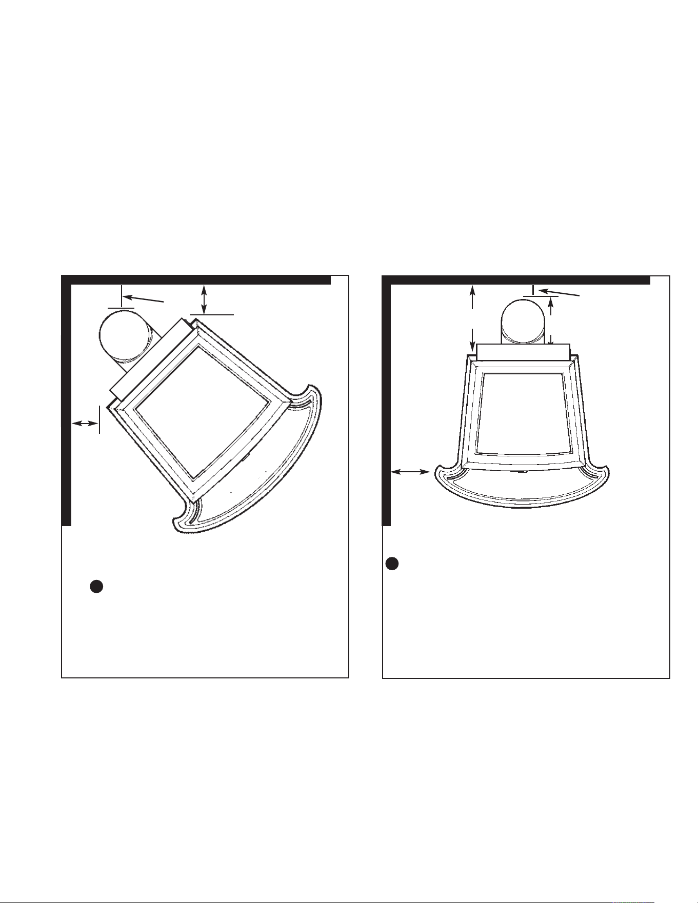
Corner Installation
Minimum Clearances
Min. Clearance from corners to
both side walls ......................1.5"
Pipe to wall
(Vertical Vent)..........................3"
Parallel Installation
Minimum Clearances
Min. Clearance from back of pipe to wall......3"
Min. Clearance from Fireplace to side wall
(Vertical vent)..................................................2"
Min. clearance from back of stove to wall
(Straight vent)...............................................11"
Illustration 5.1 Minimum Clearances: Corner
Installation
Illustration 5.2 Minimum Clearances:
Parallel Installation
3"
3"
2"
1.5"
1.5"
The surface of the Mini Franklin Gas Stove is hot when the appliance is in use. A safe installation requires that
there be adequate clearances between the Mini Franklin Gas Stove and nearby combustible materials, so that
combustible materials are not overheated. The diagrams that follow show minimum clearances between the Mini
Franklin and nearby combustible materials.
Clearances for vent terminal locations are indicated in the diagram and chart on page 10.
Refer to the manufacturer’s instructions regarding installation of your venting system through walls or ceilings.
Use only Simpson Dura-Vent GS Direct-Vent Flue Systems.
A
B
Min. 11”
8"
-------------------------------------------------------------------------------------------------------------------------------------------------------------------------------------------------------- 6
-------------------------------------------------------------------------------------------------------------------------------- Approved Venting/Chimney Configurations
Refer to Simpson Dura-Vent instructions regarding installation of your
Direct-Vent System.
Please note the following considerations for the location of the vent
terminal:
1. The horizontal run must rise
a minimum of 1/4" per foot of run
toward the vent termination.
2. The termination must not be recessed
into the exterior wall or
siding.
3. Clearances must be maintained
around the vent termination. See
illustrations on page 10.
4. Vinyl Siding
requires protection from vented heat above the
termination. Use Simpson Dura-vent Vinyl Siding Heat Shield
Kit, part 34GSS-VSS.
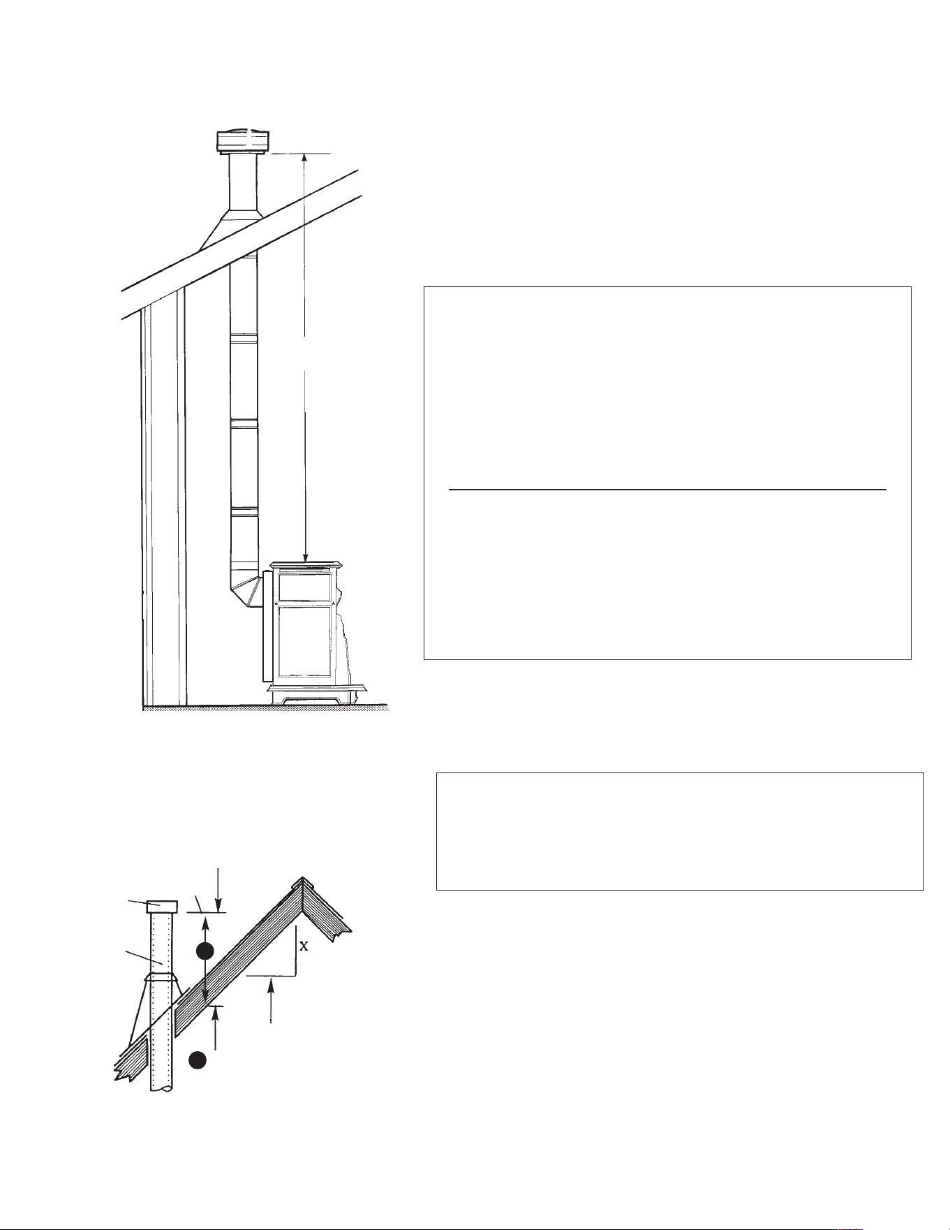
MINIMUM AND MAXIMUM DISTANCES
• Maximum rise ..............................................................6 feet
• Maximum recomended run ..........................................3 feet
• Maximum number of 90 deg elbows..................................2
(one attached to flue outlet; one to go out through wall)
Note 1. The ratio of rise to run should be a minimum of 2:1
• Wall Opening:
Masonry wall......... ..............................................7" opening
Non-masonry wall.................................framed to 10" x 10"
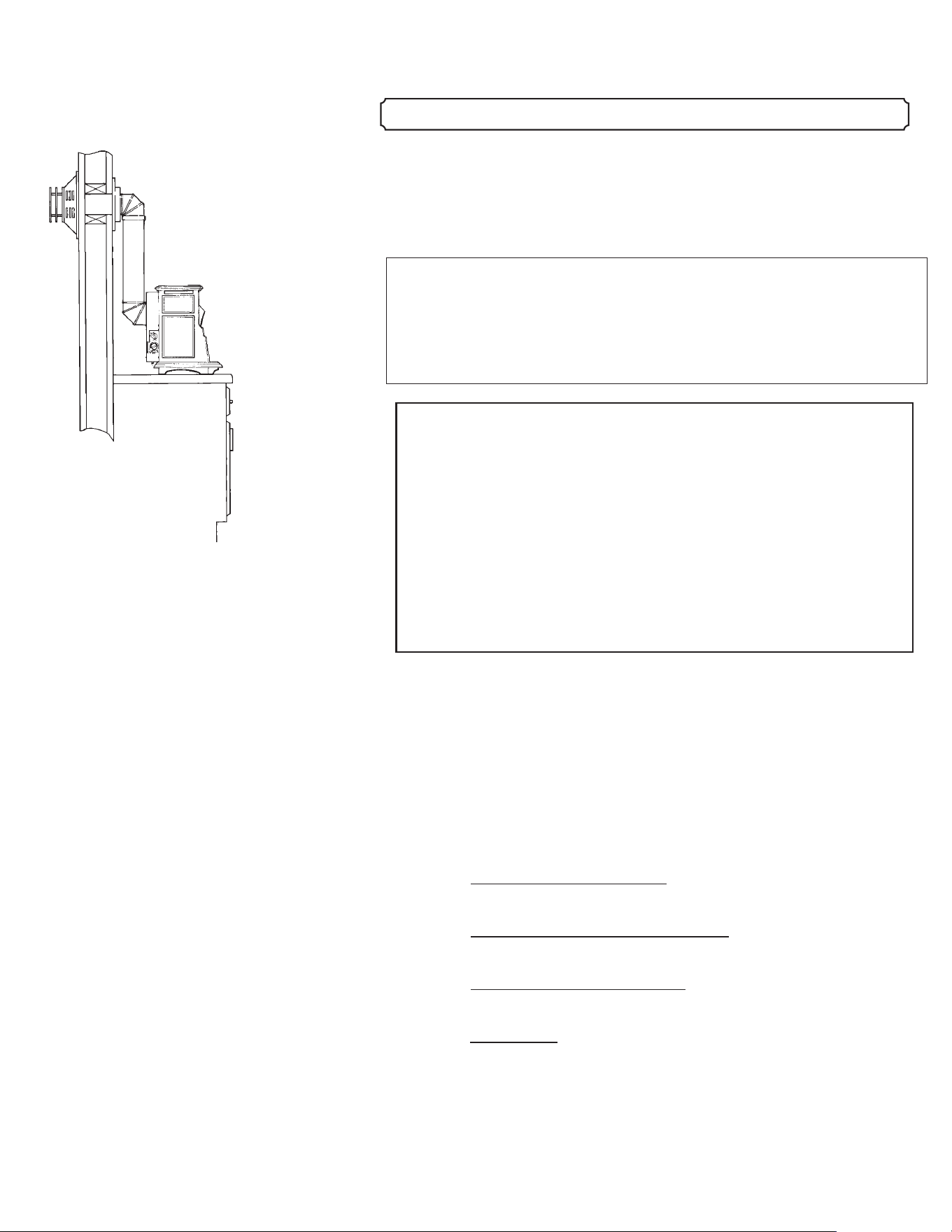
A. Side Wall Venting
In this venting configuration, the pipe rises directly from the back of
the Stove. The exhaust travels up, through two elbows, and out through a
side wall. See illustration at left.
ALL VENT CLEARANCES MUST BE MAINTAINED.
CHECK YOUR VENT CLEARANCES AGAINST THE
ILLUSTRATIONS ON PAGE 10.
!
Illustration 6.1
Side wall venting configuration.
6. APPROVED VENTING/CHIMNEY CONFIGURATIONS
-------------------------------------------------------------------------------------------------------------------------------------------------------------------------------------------------------- 7
-------------------------------------------------------------------------------------------------------------------------------- Approved Venting/Chimney Configurations
Illustration 6.2
If stove is vented straight
back, Snorkel attachment is
required.
The venting should be located so that people cannot be burned by
accidentally touching hot vent surfaces while the Stove is in operation.
The vent termination must be placed so that it cannot be damaged by
automobile doors, lawn mowers or yard equipment, or falling ice and snow.
Refer to the Simpson Dura-Vent instructions regarding installation of
your Direct-Vent system.
Please note the following considerations for the location of the vent
terminal:
1. The horizontal run must rise
a minimum of 1/4" per foot of run
toward the vent termination.
2. Clearances must be maintained
around the vent termination. See
illustrations on page 12.
3. The termination must not be recessed
into the the exterior wall or
siding.
4. Vinyl Siding
requires protection from vented heat above the
termination. Use Simpson Dura-vent Vinyl Siding Heat Shield Kit,
part #950.
MINIMUM AND MAXIMUM DISTANCES
• Maximum run ........................................................24 inches
Note: Use of a 45 deg. elbow to install in a corner location is
allowed
• Minimum Distance between the inside wall and the
back of Fireplace ...............................................................2"
• Wall Opening:
Masonry wall .......................................................7" opening
Non-masonry wall.................................framed to 10" x 10"
ALL VENT CLEARANCES MUST BE MAINTAINED.
CHECK YOUR VENT CLEARANCES AGAINST THE
ILLUSTRATIONS ON PAGE 10.
B. Side Wall Venting (straight back through wall into snorkel)
In this venting configuration, the pipe runs directly out the back of the
Stove, through an outside wall and then up with a snorkel termination cap.
See illustration at lower right.
!
-------------------------------------------------------------------------------------------------------------------------------------------------------------------------------------------------------- 8
-------------------------------------------------------------------------------------------------------------------------------- Approved Venting/Chimney Configurations
Lowest
Discharge
Opening
Listed
Cap
Listed
Gas
Vent
12"
Roof Pitch is X/12
Minimum Height
from Roof to Lowest
Discharge Opening
10' Max.
A
A
Illustration 6.3
Vertical venting configuration.
(Max height 10’)
Illustration 6.4
C. Vertical Venting (straight up through roof)
In this venting configuration, the pipe rises directly from Stove
and goes up through the roof, terminating above the roof. See
illustration 6.3.
MINIMUM AND MAXIMUM DISTANCES
• Maximum vertical rise .....................................................10'
Height of termination above roof must conform to chart
below
Roof Pitch A Minimum height from roof
to lowest discharge opening
Flat to 6/12 1.0 feet
6/12 to 8/12 2.0 feet
8/12 to 10/12 3.0 feet
10/12 to 12/12 4.0 feet
*Max rise is 10’. No additional elbows are allowed.
ALL VENT CLEARANCES MUST BE MAINTAINED.
CHECK YOUR VENT CLEARANCES AGAINST THE
ILLUSTRATIONS AT LEFT, AND PAGE 10.
!

-------------------------------------------------------------------------------------------------------------------------------------------------------------------------------------------------------- 9
-------------------------------------------------------------------------------------------------------------------------------- Approved Venting/Chimney Configurations
MANUFACTURED HOUSING INSTALLATION
The Mini Franklin Gas Stove may be installed in Manufactured Housing with
the following supplemental requirements:
(1) The appliance must be securely bolted to the floor or wall mount with steel
straps secured to the leg bolts and to the floor with minimum 1/4” lag bolts.
Contact Woodstock Soapstone Company for steel straps.
(2) The appliance must be grounded to the manufactured home trailer frame with
a No. 8 (minimum) solid conductor.
The Mini Franklin Gas Stove is currently approved only for venting with the
components listed previously on pages 3 and 4. Install the vent system according to
the manufacturer’s instructions, which are included with the components.
Note: A manufactured home (USA only) or mobile home OEM
installation must conform with the Manufactured Home
Construction and Safety Standard, Title 24 CFR, Part 3280, or, when
such a standard is not applicable, the Standard for Manufactured
Home Installations, ANSI/NCSBCS A225.1, or Standard for Gas
Equipped Recreational Vehicles and Mobile Housing, CSA Z240.4
WARNING! This unit must be installed by a qualified gas
technician in accordance with local codes or in the absence
of local codes, with the most current edition of the National
Fuel Gas Code ANSI Z223.1/NFPA 54.
!
------------------------------------------------------------------------------------------------------------------------------------------------------------------------------------------------------ 10
----------------------------------------------------------------------------------------------------------------------------------------------------------------------------------------------------- 10
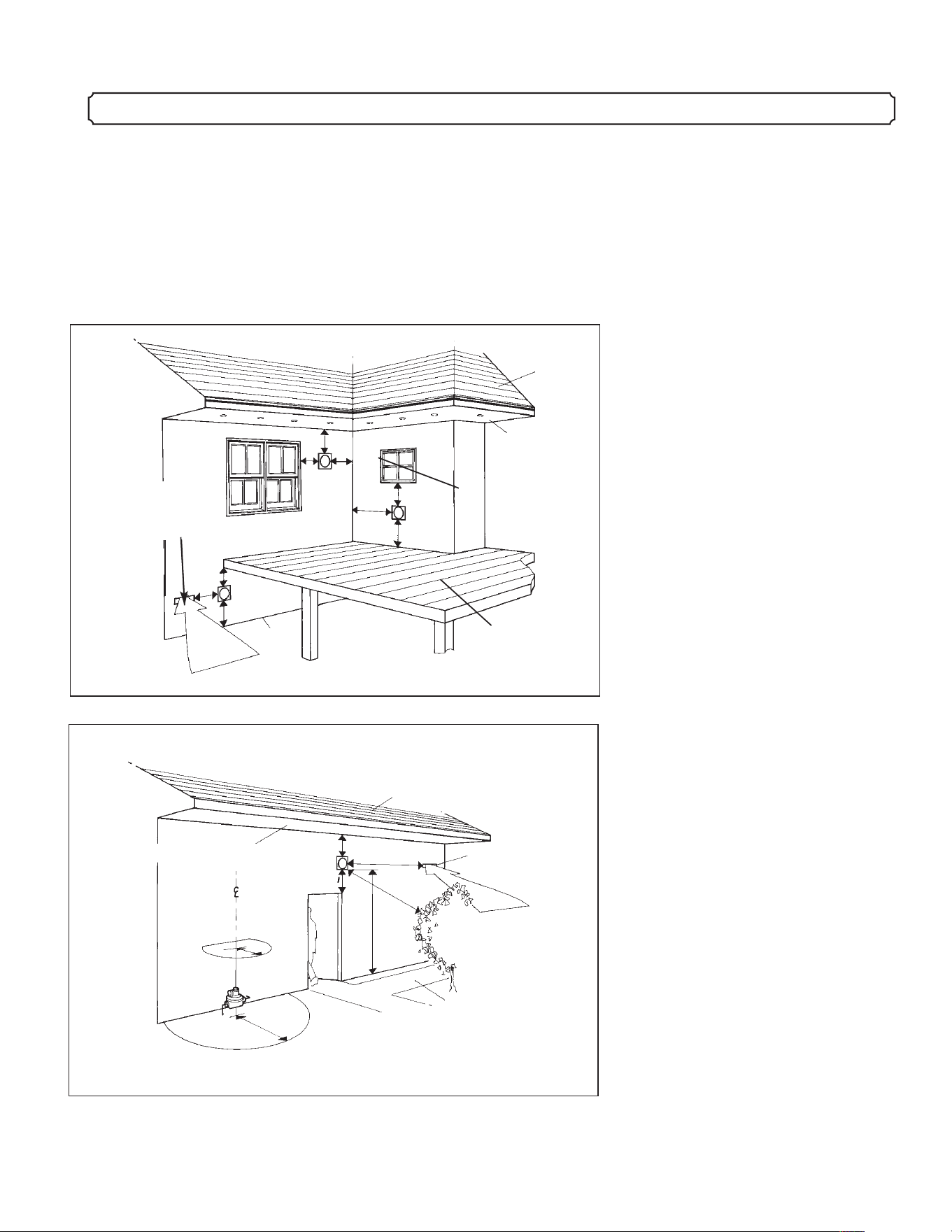
7. APPROVED VENTING/CHIMNEY TERMINAL CLEARANCES
Grade
Air
Non
Mechanical
Air Supply
G
D
H
E
C
Roof
Ventilated
Soffit
Fixed
Window
Deck
A
E
B
C
Mechanical
Air Supply
Vegetation
Roof
K
I
L
J
F
B
M
Nonventilated
Soffit
Public Sidewalk or
Driveway
A. Clearance to a permanently
closed window..................12"
B. Clearance to a window or door
that may be opened ..........12"
C. Clearance above grade. Also,
clearance over deck,
porch,
veranda or balcony .............12"
D. Clearance to non-mechanical
air supply inlet or combustion
air inlet of any other
appliance..........................12"
E. Clearance to inside corner or
adjacent wall.....................12"
F. Clearance to a non-ventilated
soffit .................................12"
G. Clearance below deck,
porch, veranda, or balcony
if completely open on two
sides..................................18"
H. Clearance to ventilated soffit
located above the terminal
within a horizontal distance
of 2 feet from the center of the
terminal.............................18"
I. Clearance around a center line
above service regulator.3 feet
J. Clearance to vegetation..3 feet
K. Clearance around a service
regulator vent outlet......6 feet
L. Clearance to a mechanical air
supply............................6 feet
M. Clearance above a paved
sidewalk or driveway on
public property. May not
terminate above a sidewalk
or driveway which is
between two single family
dwellings and serves both
dwellings.......................7 feet
Illustration 7.1
Illustration 7.2
------------------------------------------------------------------------------------------------------------------------------------------------------------------------------------------------------ 11
----------------------------------------------------------------------------------------------------------------------------------------------------------------------------------------------------- 11
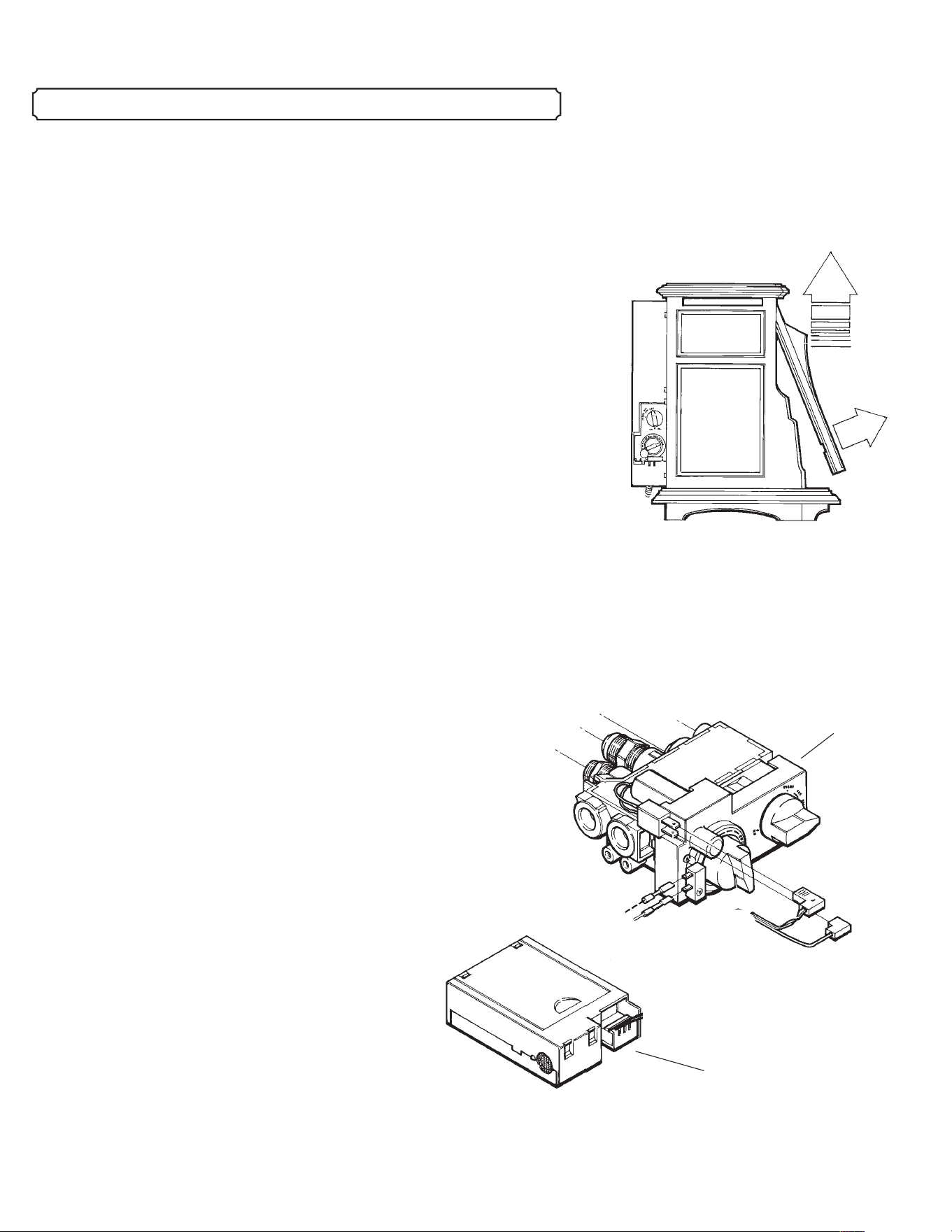
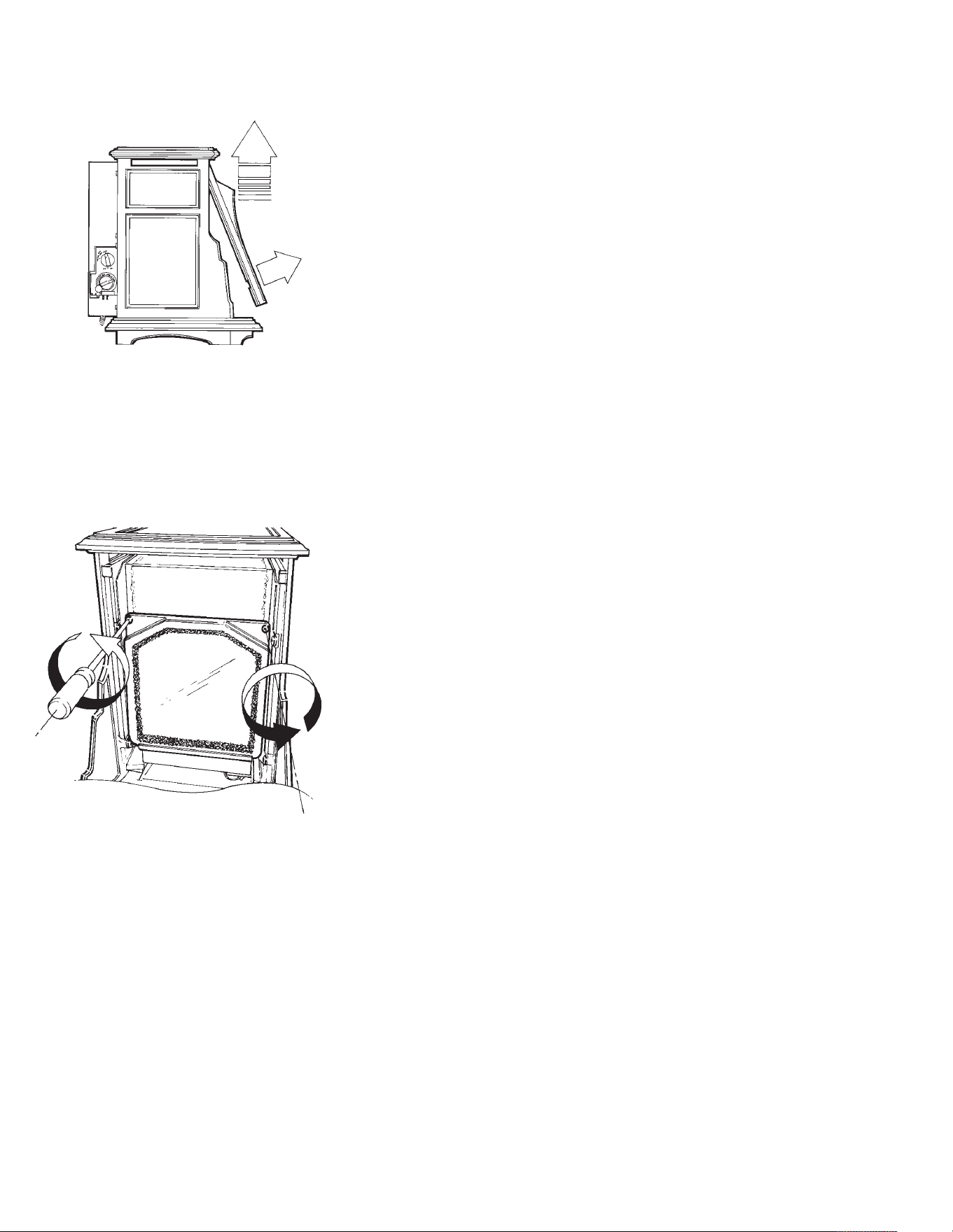
Illustration 8.1 To remove the front
casting, lift straight up under the lip
that extends over the top of the
glass.
1. INSTALLING THE LOGSET
Your Mini Franklin Gas Stove has been carefully assembled by our
craftsmen. Because of the fragile nature of the ceramic logset it is
packaged separately to ensure safe shipping, and requires minor
assembly. Please use to the following instructions to ensure proper
placement of the logset.
Remove the front casting by lifting straight up under the lip that
extends over the glass panel.
The glass panel is held in place with two screws at the top and a rail at
the bottom. Remove the two screws, and then remove the front glass
panel and frame.
The burner pan is installed in the bottom of the firebox and is secured
in place to ensure safe shipping. The logs should be placed on the
burner using the locating pins in the burner to secure them to the burner.
2. REPLACE GLASS FRONT/FRONT CASTING
Once the tile and logset have been assembled the glass panel may be
reinstalled. Be sure the bottom edge of panel fits snugly into bottom rail
and clips are fastened securely. Replace the front casting.
3. INSTALLING OPTIONAL EQUIPMENT:
Installing optional remote control:
The Mini Franklin Gas stove may be equipped with an optional
remote control. The remote has several
functions. It can turn the burner on or off,
regulate flame height or act as a
timer/thermostat. The remote control
system includes the remote transmitter, the
remote receiver, and connecting wires.
If a remote control is added, the receiver
must be wired to the gas controller. See
complete instructions in Appendix B on
page 33. Refer also to instructions for
operation packaged with the remote control
system.
8. ASSEMBLING THE FIREPLACE
Remote receiver
Gas control
valve

------------------------------------------------------------------------------------------------------------------------------------------------------------------------------------------------------ 12
----------------------------------------------------------------------------------------------------------------------------------------------------------------------------------------------------- 12
9. PRE-INSTALLATION INSPECTION
CHECKLIST FOR INSTALLER
1. Check that both intake and exhaust venting are clear of any debris or other
obstruction at the back of the Stove.
2. Check that the gas manifold is connected to both the controller and the
orifice at the back wall of the Stove and is free from damage.
3. Check that the pilot gas tube, and thermocouple are properly connected to
both the pilot assembly and gas controller.
4. Check that the piezo wire is connected to the pilot assembly.
Push in and turn right gas control knob counterclockwise to test for spark
in the Firebox near the pilot.
1. CHECK THE GAS LINE PRESSURE BEFORE CONNECTING THE STOVE TO
THE GAS LINE
The stove and its main gas valve must be disconnected from the gas supply piping system
during any pressure testing of that system at test pressures in excess of 1/2 psa (3.5kPa). If
the gas line pressure is too high it will rupture the gas control valve on the Stove.
Isolate the stove from the gas supply piping system by closing the shut-off valve during
any pressure testing of the gas supply piping system at test pressures in excess of 1/2 psa
(3.5kPa).
2. ATTACH GAS LINE TO THE CONTROL VALVE
The gas supply line is connected to the Stove gas control valve through a 1/2" flexible
connector pre-attached to the valve using a
3
/8" male NPT fitting. The gas supply line for
either propane (LPG) or natural gas (NG) should be large enough to support (25,000 Btu)
and should be connected with a male 1/2" 45 degree flare fitting. Consult local building
codes to properly size the gas supply line.
3. TEST FOR LEAKS
Test for leaks using a sniffer, soapy water or an approved leak testing spray. Check each
joint or connection from the main supply valve to the Stove. Check the connections on the
control valve as well as those in the Stove in case one loosened in shipment. Again, never
test with an open flame.
4. TEST PRESSURE THROUGH CONTROL VALUE
Test pressure to and through the control valve using a manometer on the test gauge taps
on the control valve. The line must be tested as follows:
Propane (LPG or LP):
10.5" w.c. manifold pressure
10. CONNECTING THE GAS SUPPLY/
TESTING THE FLAME

11.0" w.c. minimum inlet supply for adjustment
Natural gas:
3.5" w.c. manifold pressure
4.0" w.c. minimum inlet supply for adjustment
5. LIGHT THE STOVE, FOLLOWING LIGHTING DIRECTIONS ON
PAGE 21. (FRONT GLASS AND FRONT CASTING MUST BE IN
PLACE PRIOR TO LIGHTING)
6. The Air Shutter covers the end of the venturi opening at the base of the
Burner Pan and controls the air/fuel mixture. The Shutter has been pre-set to
provide an optimum yellow flame at sea level when the Logset is warmed up.
If you are operating a Natural Gas Stove at an elevation other than sea level,
it may be necessary to adjust the position of the air shutter. Wait fifteen minutes
after first lighting the Burner to see if the flame changes from mostly blue to
bright yellow. If it remains blue than there is too much air getting into the mix.
If the flame turns orange or smoky then there is too little air getting into the
mix.
Note: Allow Stove to cool before handling.
------------------------------------------------------------------------------------------------------------------------------------------------------------------------------------------------------ 13
----------------------------------------------------------------------------------------------------------------------------------------------------------------------------------------------------- 13
To adjust the amount of air, remove front casting, glass panel and logset assembly.
Carefully lift the burner pan up and out of the firebox, avoid damaging the orifice at the rear. The air
shutter is located at the end of the venturi tube attached to the bottom of the burner pan.
Adjust the shutter by loosening the attachment screw which holds it to the venturi tube. Slidet the shutter
open to allow more air into the venturi or closed to restrict the amount of air. Tighten screw.
Replace the burner pan by inserting the venturi under the back edge of the firebox and pushing it carefully
over the orifice. Note: When the burner pan is properly located it will sit squarely in the firebox with equal
space approximately 1/4" between the pan and the sides of the firebox.
WARNING: This unit must be installed by a qualified gas technician in
accordance with local codes or in the absence of local codes, with the most current
edition of the National Fuel Gas Code ANSI Z223.1/NFPA 54.
11. AIR SHUTTER ADJUSTMENT
!
------------------------------------------------------------------------------------------------------------------------------------------------------------------------------------------------------ 14
----------------------------------------------------------------------------------------------------------------------------------------------------------------------------------------------------- 14
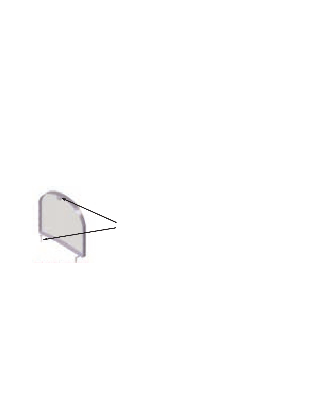
The Screen Barrier for the Glass Front
A screen barrier has been installed on the front of your Mini Franklin Gas Stove to reduce the risk of
burn from the hot viewing glass, It has been installed at the factory for the protection of children and
other at-risk individuals. It should not be removed.
If the screen barrier becomes damaged, it shall be replaced with the barrier made by Woodstock
Soapstone Company for the Mini Franklin Gas Stove. The screen barrier is attached to the front
casting, and should not be removed even to service the stove.
Installation and repair should be done by a qualified service person. The stove should be inspected
before use and at least annually by a professional service person. More frequent cleaning might be
required due to excessive lint from carpeting, bedding material, and so on. It is imperative that control
compartments, burners and circulating air passageways be kept clean.
Note: clothing or other flammable material should not be placed on or near the appliance. Do not
attempt to dry mittens or gloves by placing them on the stove.
The screen barrier is pictured below.
The screen barrier is held
permanently in place with
two clips at the bottom
and one at the top.

--------------------------------------------------------------------------------------------------------------------------------------------------------------------Warranty Registration
12. TESTING CHECK LIST AND WARRANTY REGISTRATION
TESTING CHECK LIST Installer Owner
1. Check all gas connections, use soapy water or mechanical
sniffer to check for leaks:
a. Control valve connection ______ ______
b. Main gas line valve ______ ______
c. (other?) ______ ______
2. Glass front:
a. No damage to glass ______ ______
b. All latches functioning properly ______ ______
c. Glass securely in place in frame ______ ______
d. Gasket even, snug against firebox ______ ______
3. Safety controls:
a. Pilot failure shuts off main valve ______ ______
b. Pressure relief lid on the back of
the firebox is properly seated, and
not open. ______ ______
4. Operate all valves and controls: ______ ______
a. Main supply line valve ______ ______
b. Pilot control valve ______ ______
c. Ignitor ______ ______
d. Main burner ______ ______
e. Flame HI-LO ______ ______
f. Remote Thermostat ______ ______
Installer Owner
5. Flame:
a. Fifteen minutes after ignition, flames should
have a blue/yellow appearance and with the
flame control set on HIGH, the flames
should be about 2" to 6" high. ______ ______
(1). If the flames are totally blue, reduce the
amount of air by adjusting the burner air shutter.
(2). Orange-smoky flames: increase the amount
of air to the burner by opening the burner air
shutter.
b. After up to one hour's burn, there should be
no sign of soot. ______ ______
If during that test burn the flame lengthens and
becomes smoky, is more orange-yellow than yellow,
or there is some collected soot after an hour, do the
following:
(1). Check that the log set is securely in place.
If the logset is not exactly in the right place,
the flame impingement will be wrong.
(2). If log set is properly placed, adjust burner air
shutter setting.
This installation has been performed safely and to our satisfaction, signed:
_________________________________________ ___________________________________________
Installer, Date Owner, Date
Please fold so that our return address shows. Tape the edges together and mail.
No postage is necessary.
WARRANTY REGISTRATION
Owner Name: __________________________________ Telephone: ____________________
Address: ____________________________________________________________________
___________________________________________________________________________
Installer Name:_______________________________________________________________
Company_______________________________________Telephone: ___________________
Address: ____________________________________________________________________
___________________________________________________________________________
Stove Model: ________________________________________________________________
Serial #: _______________________________________LPG ___________NG ___________
Purchase Date: _________________________Installation Date: ________________________
-------------------------------------------------------------------------------------------------------------------------------------------------------------------------------------------------------16
------------------------------------------------------------------------------------------------------------------------------------------------- Troubleshooting – Installer Only
13. TROUBLESHOOTING – INSTALLER ONLY
(CERTIFIED GAS TECHNICIAN ONLY)
Pilot will not
light despite
repeated clicking
of ignitor.
1. Air in gas lines.
2. No ignitor spark, either
checked visually or proven
by lighting the pilot with a
match.
3. Low gas pressure.
a. Bleed gas lines.
a. Check for loose or disconnected wires.
b. Ignition wire is broken or corroded: replace.
c. Misaligned electrode, wrong gap: gap should be 1/8".
d. Electrode insulator is cracked or tip is corroded: replace electrode.
a. Wrong inlet pressure; adjust inlet pressure regulator to 4" w.c. for
NG, 11" w.c. for LP.
a. Adjust inlet pressure regulator to 4" w.c. for NG, 11"w.c. for LP.
a. It must be placed so that the top 3/8" is engulfed in flame from the
pilot.
a. Clean with fine emery cloth.
a. Check open circuit voltage with volt meter, should be between 18mV
and 28mV with induced heat source applied. If less than 18mV, replace.
a. Verify open-circuit thermocouple voltage is between 18mV and 28mV
with induced heat source applied. If so, electromagnet is faulty and
valve must be replaced.
a. Check venting for blockage, loose connections, and that configuration
meets requirements for the stove.
a. Call Woodstock Soapstone Company for windguard options designed
for your stove and installation.
a. Check that gas control knob is “ON”.
a. Increase set temperature on remote, go to manual mode, increase gas
flow manually with switch, or knob on valve.
a. Remove and blow out with compressed air or clean out with brush.
PROBLEM CAUSE SOLUTION
Pilot will not
stay lit.
1. Low gas pressure.
2. Thermocouple not properly
inserted in pilot assembly.
3. Thermocouple has dirty tip.
4. Defective thermocouple.
5. Defective electromagnet,
check operation as follows:
6. Lack of oxygen.
7. High wind.
Pilot burning,
main burner will
not light.
1. Gas Control knob in wrong
position.
2. Temperature set in remote
transmitter is lower than
room temperature, and remote
set to Auto.
3. Gas supply orifice is
clogged.
*Optional Equipment
------------------------------------------------------------------------------------------------------------------------------------------------------------------------------------------------------ 17
------------------------------------------------------------------------------------------------------------------------------------------------- Troubleshooting – Installer Only
Delayed Ignition
of burner.
1. Burner pan is not in
correct position (pilot cannot
ignite fuel).
2. High Wind.
3. Low manifold pressure.
4. Low pilot flame.
5. Flame Impingement
(logset position).
1. Venting is blocked or
interrupted.
2. Low gas pressure.
1. High wind.
2. Pressure relief lid out of
position.
1. Pressure relief lids not
seated correctly.
2. Curing of paint and gasket
cement.
a. Reseat the burner pan following the instructions in the manual
ensuring that the venturi is positioned over the orifice and pilot flame is
running over the top suface of the burner pan.
a. Call Woodstock Soapstone Company for wind guard options designed
for your stove and installation.
a. Use manometer to check output from controller. Must be 3.5" w.c. for
N.G. and 10.5" w.c. for LP. (Check inlet pressure first).
a. Adjust the setting of the “pilot” valve on the controller. (Check inlet
pressure first).
a. If the logset is covering the pilot output contact Woodstock Soapstone
for information.
a. Confirm pressure relief lids on top of and at the rear of firebox are
properly seated.
a. It is normal to experience an odor for the first few hours of constant
use; this will discontinue with normal use.
a. Check that the pipe joints are locked together and free from
obstruction.The inner pipe is more critical than the outer wall.
b. Be sure that the pipe system is completely without interruptions from
the fireplace to the outside termination cap.
a. Confirm inlet pressure.
b. Make sure the gas storage tank is not too low. (Under 20%).
c. Check for moisture in gas supply system.
d. Check for contaminants in gas supply system.
a. Shut off fireplace system and wait for wind to die down.
b. Call Woodstock Soapstone Company for wind guard options designed
for your stove and installation.
a. Confirm pressure relief lid at the rear of firebox is properly seated.
PROBLEM CAUSE SOLUTION
Odor.
Low flame or
flame goes out
after a short
burn.
Sporadic
changes of flame
level/lifting of
flame.
BEFORE YOU USE YOUR GAS FIREPLACE
1. Determine that the gas shut-off valve is in the open position
(there may be more than one shut-off valve between the
Fireplace and the main gas supply; make sure all are turned on).
2. If the Fireplace has not been used for some time, there will
be air in the gas supply line. This will be automatically
purged when you light the pilot.
3. Smell for gas, especially near the floor if you are using LPG
(propane) as it is a heavy gas and any leaked gas would stay
near the floor. Natural gas is lighter than air and will rise. If
you smell gas, do not attempt to light the appliance. Follow
“What to do if you smell gas” instructions shown on the
cover of the manual.
14. OPERATING YOUR GAS FIREPLACE
----------------------------------------------------------------------------------------------------------------------------------------------------- Operating Your Gas Fireplace
FOR YOUR SAFETY READ BEFORE LIGHTING
WARNING: IF YOU DO NOT FOLLOW THESE INSTRUCTIONS
EXACTLY, A FIRE OR EXPLOSION MAY RESULT CAUSING
PROPERTY DAMAGE, PERSONAL INJURY OR LOSS OF LIFE.
This appliance has a pilot. When lighting the pilot, follow these
instructions exactly.
BEFORE OPERATING, smell all around the appliance area for gas.
Be sure to smell next to the floor because LP gas is heavier than air
and will settle on the floor.
WHAT TO DO IF YOU SMELL GAS:
Do not try to light any gas appliance.
Do not touch any electric switch; do not use any phone in your
building.
Immediately call your gas supplier from a neighbor’s phone.
Follow the gas supplier’s instructions.
If you cannot reach your gas supplier, call the fire department.
Use only your hand to push in or turn the gas control knob. Never
use tools. If the knob will not push in or turn by hand, don’t try to
repair it. Call a qualified service technician. Force or attempted
repair may result in fire or explosion.
Do not use this appliance if any part has been under water.
Immediately call a qualified service technician to inspect the
appliance and to replace any part of the control system and any gas
control that has been under water.
TO LIGHT THE PILOT
1. PUSH THE GAS CONTROL KNOB IN COMPLETELY AND
WHILE THE KNOB IS PUSHED IN, TURN IT REPEATEDLY
COUNTERCLOCKWISE FROM "IGN" TO "PILOT". EACH TIME
YOU TURN THE KNOB TO "PILOT" YOU WILL HEAR A CLICK
AS IT PRODUCES A SPARK.
– When you push the control knob in, you are letting gas into the firebox.
– Each time you turn the knob to the left and hear a click, you are
producing a spark.
2. IF THE PILOT DOES NOT LIGHT IN THE FIRST 5-6
SECONDS, STOP.
– Turn the control knob to the "OFF" position. Wait 5 minutes for the
15. LIGHTING INSTRUCTIONS
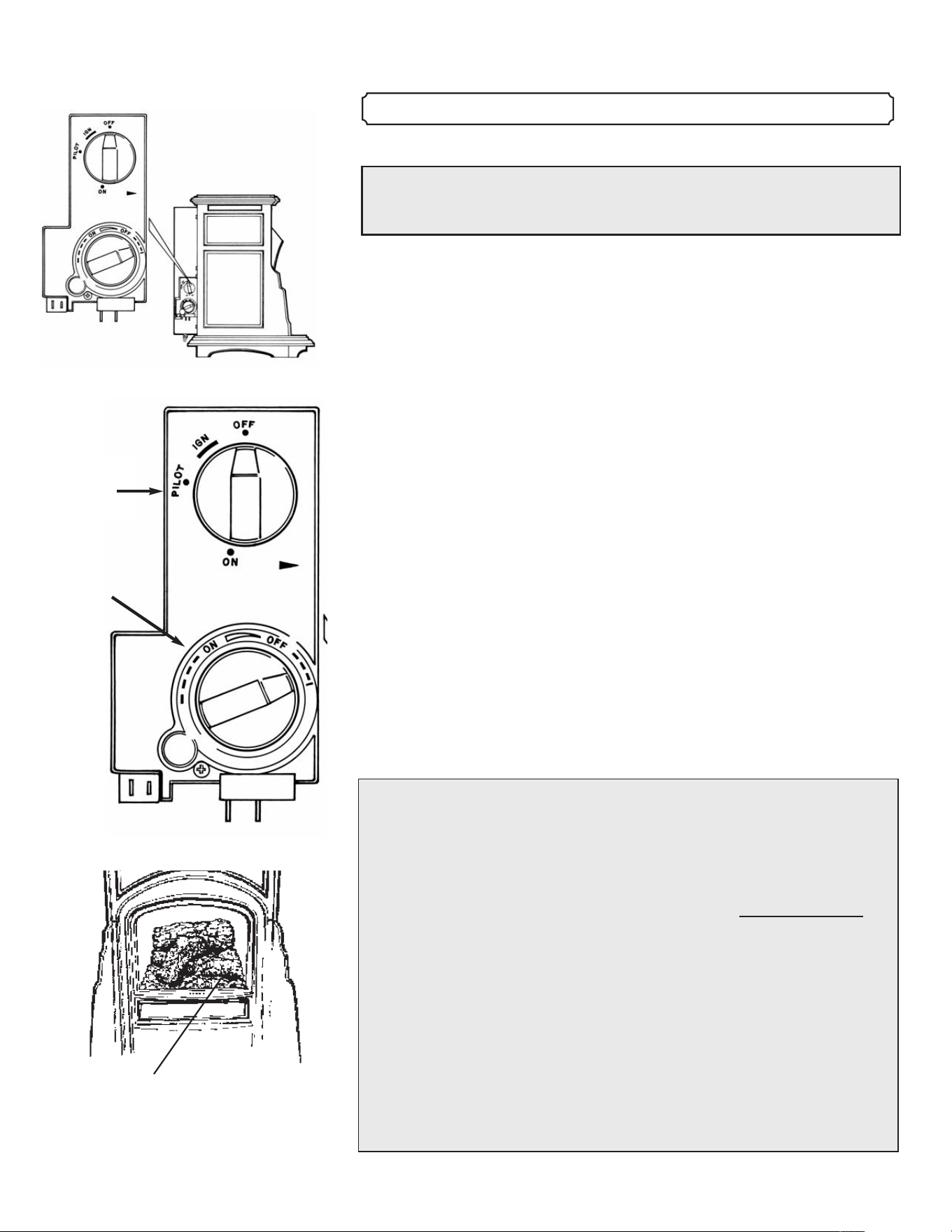
------------------------------------------------------------------------------------------------------------------------------------------------------------------------------------------------------ 18
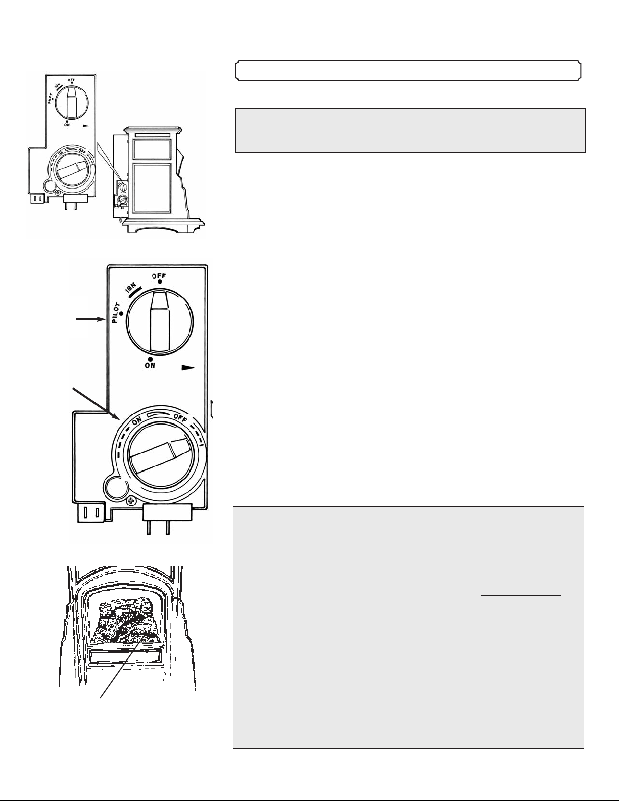
Look for Pilot
here.
BEFORE LIGHTING YOUR STOVE READ THESE
INSTRUCTIONS CAREFULLY!
DO NOT LIGHT THE STOVE IF YOU SMELL GAS!
TO LIGHT THE PILOT
1. PUSH THE GAS CONTROL KNOB IN COMPLETELY AND
WHILE THE KNOB IS PUSHED IN, TURN IT REPEATEDLY
COUNTERCLOCKWISE FROM "IGN" TO "PILOT". EACH
TIME YOU TURN THE KNOB TO "PILOT" YOU WILL HEAR
A CLICK AS IT PRODUCES A SPARK.
– When you push the control knob in, you are letting gas into the firebox.
– Each time you turn the knob to the left and hear a click, you are
producing a spark.
2. IF THE PILOT DOES NOT LIGHT IN THE FIRST 5-6
SECONDS, STOP.
– Turn the control knob to the "OFF" position. Wait 5 minutes for
the gas to dissipate before attempting to light the stove again.
Flame
adjustment
knob
Gas
control
knob
------------------------------------------------------------------------------------------------------------------------------------------------------------------------------------------------------ 19
– If you attempt to light the stove too soon the accumulated gas will
ignite, causing an explosion.
3. WHEN THE PILOT LIGHTS, CONTINUE TO HOLD THE
KNOB IN FOR 10 SECONDS SO THE PILOT WILL STAY LIT.
– When the pilot lights a small flame will be visible below the logset
at the right front corner of the firebox.
– Depressing the gas control for 10 seconds after the pilot is lit
warms the thermocouple.
– Release the knob. The pilot will remain lit.
TO LIGHT THE BURNER
1. CONFIRM THE PILOT IS LIT.
– The pilot must be lit before the burner will light.
– Follow instructions above if pilot is not lit.
2. TURN THE GAS CONTROL KNOB COUNTERCLOCKWISE
FROM "PILOT" TO "ON". THE BURNER WILL IGNITE
– If flames do not appear in 10 seconds it may be necessary to turn
the flame adjustment (left) knob counterclockwise until flames
appear.
NOTE: Flame height can be controlled manually at the control panel
using the left knob; at the rear of the stove using the HI/LO -
ON/OFF switch; or with the optional remote control.
NOTE: Knob cannot be turned from "PILOT" to "OFF" unless
depressed slightly. Do not force or use tools.
TO TURN OFF GAS TO APPLIANCE
To turn the main burner off manually turn the ON-PILOT-OFF knob
clockwise to pilot. In this position the flames from the main burner will be
extinguished, but the pilot will remain lit. The left flame adjustment knob may
also be used to turn the burner off by turning it clockwise until it stops. The
optional remote control can also extinguish the main burner by simply holding
the flame adjustment button in the LO position until the flames go out.
CAUTION: HOT WHILE IN OPERATION. DO NOT TOUCH. KEEP
CHILDREN, CLOTHING, FURNITURE, GASOLINE AND OTHER
LIQUIDS HAVING FLAMMABLE VAPORS AWAY.
WARNING: Improper installation, adjustment, alteration, service or
maintenance can cause injury or property damage. Refer to the owner’s
information manual provided with this appliance. For assistance or additional
information consult a qualified installer, service agency or the gas supplier.
CAUTION: Do not operate this appliance with glass removed, cracked or
broken. Replacement of the panel(s) should be done by a licensed or qualified
service person.
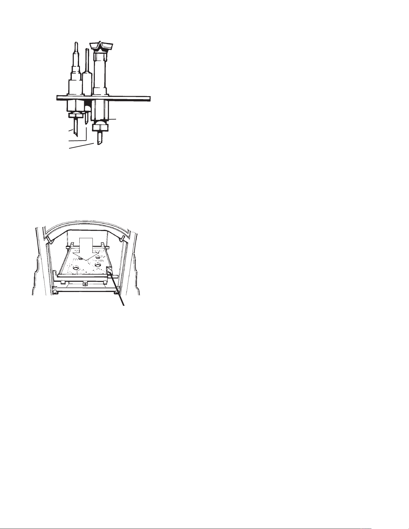
--------------------------------------------------------------------------------------------------------------------------------------------------------------------- Lighting Instructions
Illustration 15.3 The pilot is
located next to the thermocouple.
The pilot flame is visible on the
right side of the firebox.
Thermocouple
Pilot
--------------------------------------------------------------------------------------------------------------------------------------------------------------------- Lighting Instructions
------------------------------------------------------------------------------------------------------------------------------------------------------------------------------------------------------- 20
Technical Note:
HOW THE PILOT SAFETY CONTROL WORKS: When lit, the pilot
flame warms a thermocouple. The heated thermocouple produces a small
electrical current that activates an electromagnet which keeps the pilot gas
supply valve open. When you hold down the control knob after the pilot
initially lights, you are manually keeping open the gas supply until the
thermocouple warms up enough to automatically keep the gas supply valve
open.
Should the pilot blow out, the thermocouple will cool and the
electromagnet will close the gas supply valve and shut off the supply of gas. If
pilot goes out after being lit long enough to warm the thermocouple, the
thermocouple must cool down before the electromagnet will allow the gas
valve to reopen. This safety mechanisim can take up to 30 seconds and
produces an audible “click”.
ADDITIONAL NOTES
1. Check that the flames are evenly distributed. In LP burning stoves
they will be mostly blue for the first 15 minutes and then will change
to yellow/orange. NG stoves will remain very blue/translucent. There
may be a slight amount of condensation on the glass. This will
disappear when the fireplace heats up.
2. If this is the first time you have burned your new fireplace for any
length of time, you may smell the fireplace paint curing. This is
normal and will go away within a few hours.
3. The adhesive on the window gasket will also take a few days to
cure. This process will create an unpleasant odor. This is normal
and will go away after about 10 to 12 hours of use on High.
4. To completely shut off the Stove, including the pilot, turn the Gas
Control Knob to the “OFF” position. It is a good idea to turn the Gas
Control Knob to “OFF” and turn the manual gas valve on the supply
line to “OFF” if the stove will not be used for any length of time.
This turns off the pilot, the burner, and the gas supply.
WARNING
Do not attempt to decrease flame size or heat output by closing the manual
gas supply valve. This valve should always be in a fully open position while
the appliance is in operation.
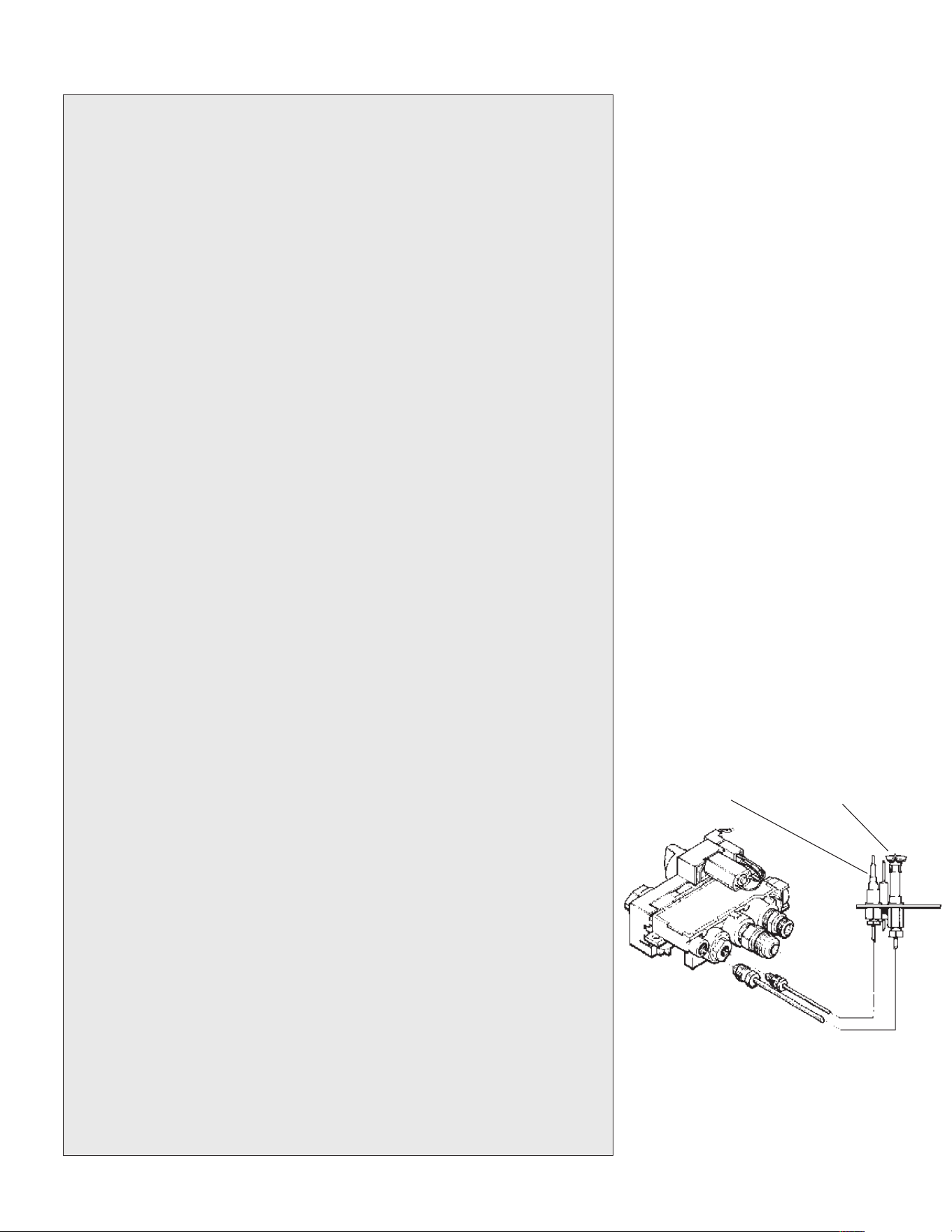
Illustration 15.4 The pilot assembly
is located on the right side of the
firebox.
Thermocouple
Spark Electrode
Pilot
Illustration 15.5 When the pilot is
lit, the flame will be clearly visible
at the right side of the firebox,
just to the right side of the burner
pan.
Pilot
------------------------------------------------------------------------------------------------------------------------------------------------------------------------------------------------------ 21
--------------------------------------------------------------------------------------------------------------------------------------------------------------------------Safety Instructions
WARNING: If you do not follow these instructions exactly, a fire or explosion may result causing property
damage, personal injury, or loss of life.
16. SAFETY INSTRUCTIONS
FOR YOUR SAFETY READ BEFORE OPERATING
A. This appliance has a pilot that must be
lighted by hand. When lighting the pilot,
follow these instructions exactly.
B. BEFORE OPERATING smell all around
the appliance area for gas. Be sure to
smell next to the floor because some gas
is heavier than air and will settle on
the floor.
WHAT TO DO IF YOU SMELL GAS
• Do not try to light any gas appliance.
• Do not touch any electric switch; do not use
any phone in your building.
• Immediately call your gas supplier from a
neighbor’s phone. Follow the gas supplier’s
instructions.
• If you cannot reach your gas supplier. Call
the fire department.
C. Use only your hand to push in or turn the
gas control knob. Never use tools. If the
knob will not push in or turn by hand, don’t
try to repair it. Call a qualified service
technician. Force or attempted repair may
result in a fire or explosion.
D. Do not use this appliance if any part has
been under water. Immediately call a
qualified service technician to inspect the
appliance and to replace any part of the
control system and any gas control that has
been under water.
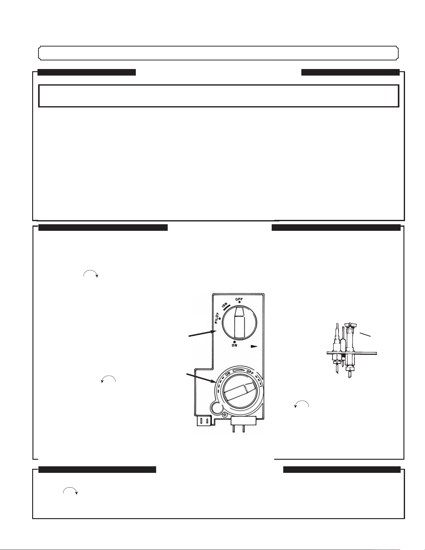
LIGHTING INSTRUCTIONS
1. STOP! Read the safety information on the
panel above.
2. Push in gas control knob slightly and
turn clockwise to “OFF”.
NOTE: Knob cannot be turned from “PILOT”
to “OFF” unless knob is pushed in slightly.
Do not force.
3. Wait five (5) minutes to clear out any gas.
Then smell for gas, including near the floor.
If you then smell gas. STOP! Follow “B” in
the safety information above on this label.
If you don’t smell gas, go to the next step.
4. Push gas control knob in completely and
turn counterclockwise repeatedly
from “IGN” to “PILOT” (audible click)
5. Find pilot. The pilot is located below the
logset in the forward right corner area of
the firebox.
6. Continue to hold the control knob in for
about 10 seconds after the pilot is lit.
Release knob and it will pop back up.
Pilot should remain lit. If it goes out,
repeat steps 4 and 5.
* If knob does not pop up when released,
stop and immediately call your service
technician or gas supplier.
* If the pilot will not stay lit after several
tries, turn the gas control knob to “OFF”
and call your service technician or gas
supplier.
7. Turn gas control knob counter clockwise
to ON, turn flame adjustment knob
counter clockwise until flames appear.
TO TURN OFF GAS TO APPLIANCE
Push in gas control knob slightly and turn
clockwise to “OFF.”
NOTE: Knob cannot be turned from “PILOT” to
‘OFF” unless knob is pushed in slightly. Do not
force.
Turn manual gas supply valve off if stove
will not be used for an extended length of
time.
Pilot
Burner
Assembly
Pilot
Flame
adjustment
knob
Gas
control
knob
------------------------------------------------------------------------------------------------------------------------------------------------------------------------------------------------------ 22
-------------------------------------------------------------------------------------------------------------------------------------------------------------------------- Optional Controls
REMOTE CONTROL UNIT
The Mini Franklin gas stove is available with an optional remote control.
The remote can adjust flame height, turn the main burner on and off when pilot
is lit, as well as function as a timer or thermostat for your stove.
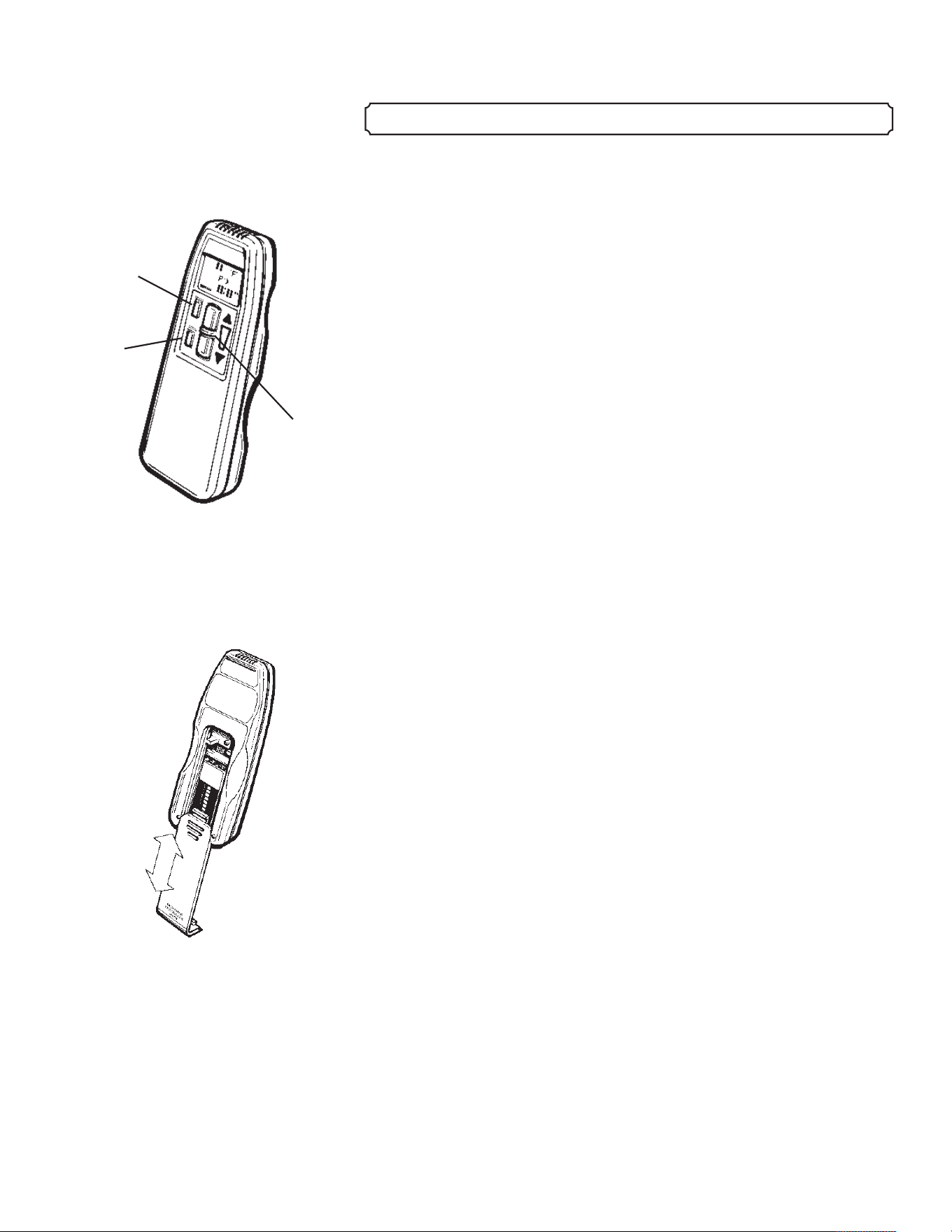
The remote control unit has two main components, a remote transmitter
(see diagram 17.1) and a receiver.
The battery operated remote control has two main parts:
1. The Remote Transmitter
(1- 9 volt battery)
2. The Remote Receiver
(4 AA batteries)
THE REMOTE TRANSMITTER HAS THE FOLLOWING
FEATURES:
Main Control Pad
“ON-OFF” “HI-LO” buttons
Mode indicators
Ambient temperature read out
Thermostat temperature setting
Clock
Timer
Battery condition
Detailed instructions for setting and operating the remote control unit
are located under the sliding cover on the back of the transmitter.
The 9V battery is also located under the cover. Further instructions
are included from the manufacturer.
A wiring diagram for installation can be found on page 33 in
this manual. ( Appendix B)
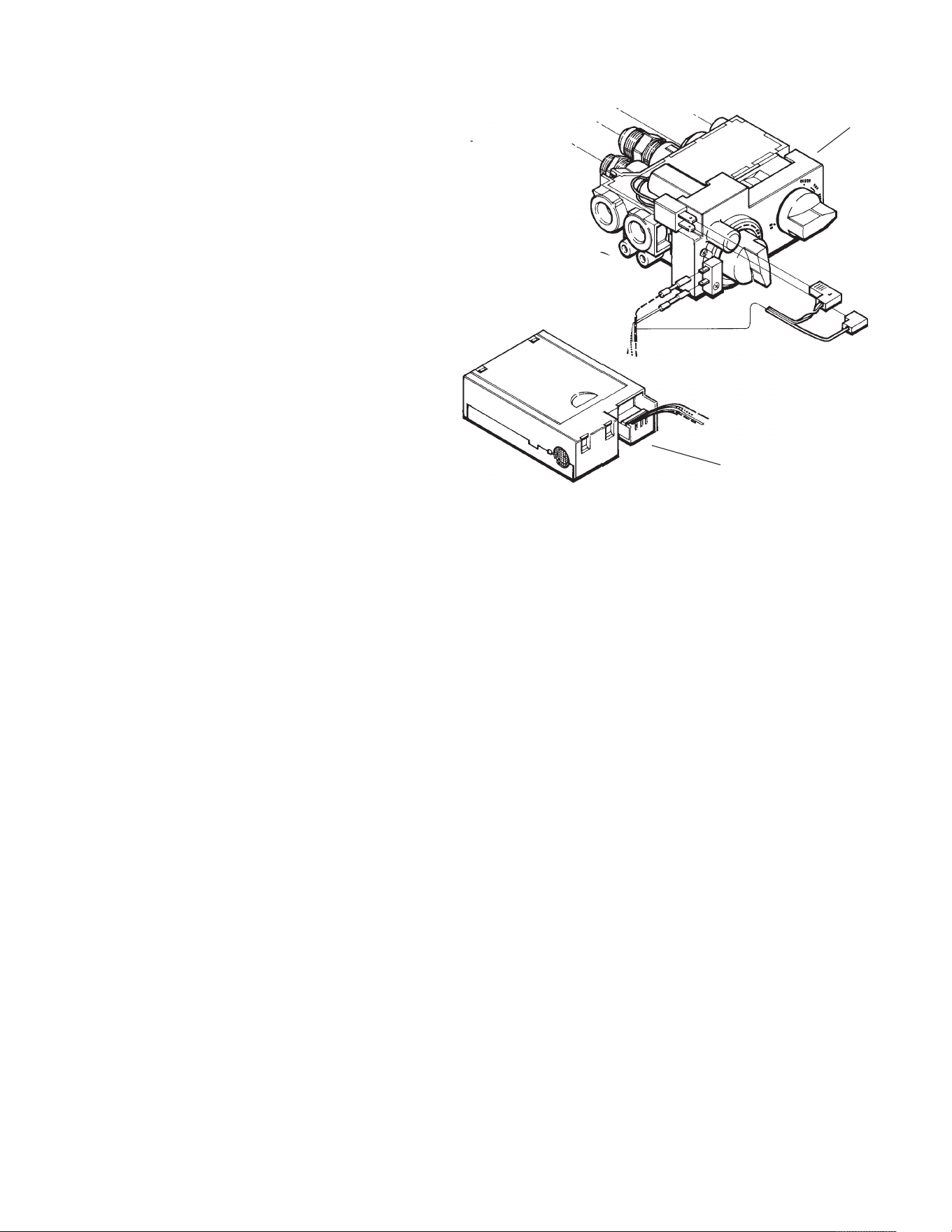
The Remote Receiver must be installed in order to operate the
Fireplace using a Remote Transmitter.
Once the remote control receiver has been wired into the control
valve, and the transmitter has been properly set it can be used to
control the stove in several ways.
• Flame adjustment - the height of the flames can be adjusted up and
down using the large buttons on the transmitter. This will regulate the
heat output of the stove. If the flame is adjusted to the minimum the
main burner flame will be extinguished. The burner will re-ignite
when the flame adjustment is increased.
• As a thermostat - A specific temperature can be maintained
automatically using the remote control unit. Once a desired
17. REMOTE CONTROL
Illustration 17.1 The remote
transmitter controls flame height,
and acts as a thermostat.
ON/OFF
Switch
UP/DOWN
Thermostat
Control
Buttons
Auto
Timer
Illustration 17.2 The transmitter
battery (9V) and programming
instructions are under the
sliding cover.
temperature has been set in the transmitter
the stove will automatically cycle on and
off and/or adjust flame height to maintain
it.
• As a timer - specific on and off times
can be pre-set in the transmitter and will
be maintained in this mode.
NOTE: If either set of batteries fail
in the Transmitter or Receiver the
Remote Transmitter will not function.
CAUTION: If the batteries fail in
either your Remote Transmitter or the
Remote Receiver, the Fireplace will
continue doing whatever it was doing when the batteries failed. If it
was burning, it will continue burning until you manually turn it off.
If it was off, it will remain off. There is no immediate danger in this
situation. You could come home to either a very warm house or, if
the Fireplace is your sole source of heat, a very cold house which
offers the eventual danger of frozen water pipes.
-------------------------------------------------------------------------------------------------------------------------------------------------------------------------------------------------------23
-------------------------------------------------------------------------------------------------------------------------------------------------------------------------- Optional Controls
Illustration 17.3 Remote
Receiver Wiring
Remote receiver
Gas control
valve
Diode
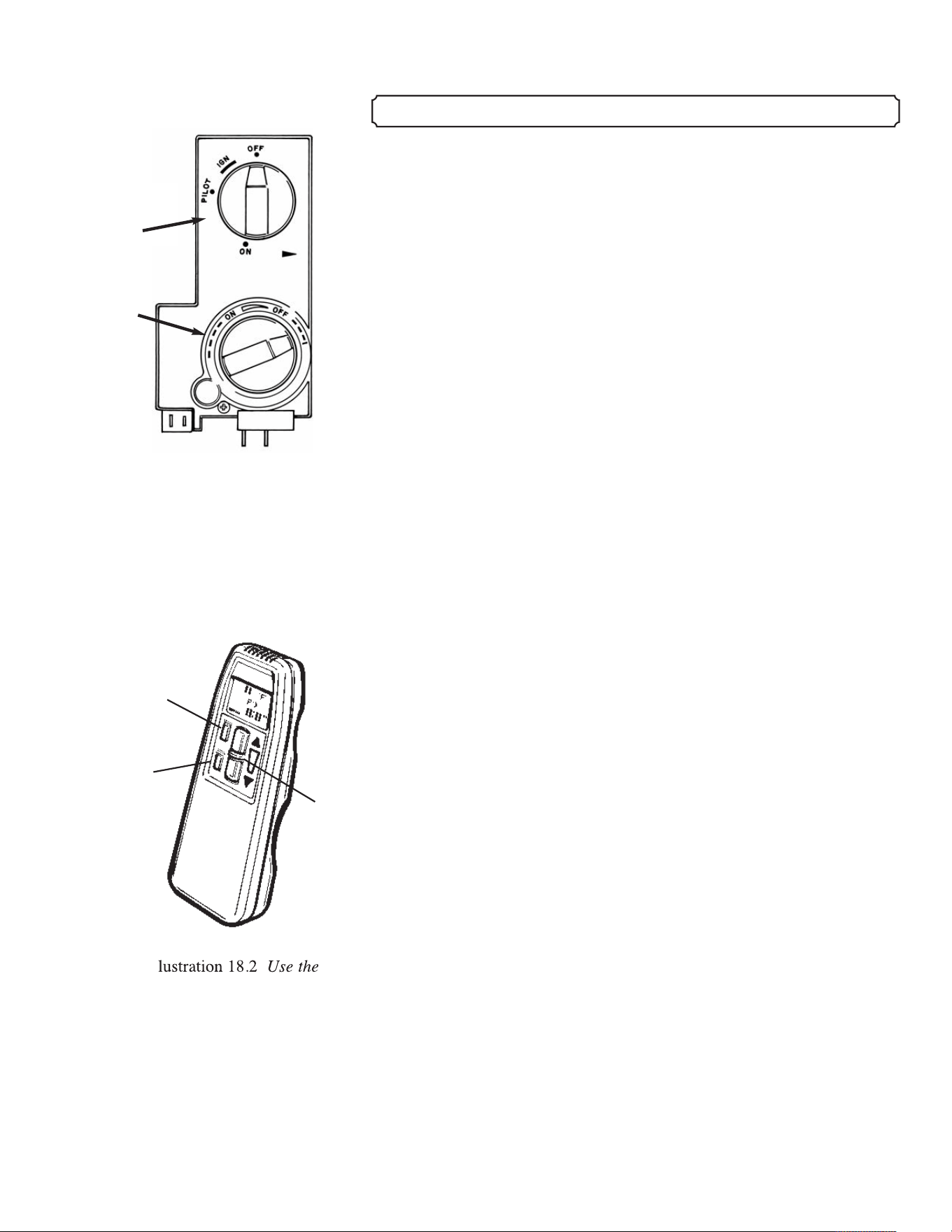
Illustration 18.1 To light
the main burner with the
remote the pilot must be lit
and the gas control knob
turned to ON.
Illustration 18.2 Use the
large buttons to turn the
main burner ON or OFF
and control flame height.
--------------------------------------------------------------------------------------------------------------------------- Lighting the Fire for Remote Control Owners
To light the main burner with the optional remote:
Confirm the pilot is lit. If not lit, follow instructions for
lighting pilot on page 21.
Turn the right gas control knob counterclockwise to the ON
position.
Use the flame adjustment button on the remote to increase gas
flow until flames appear. If flames appear immediately when
the gas control knob is turned to the ON position the remote
can then be used to control the flame height and turn the
burner ON or OFF with the large flame adjustment buttons.
Check that the flames are evenly distributed. They will be
mostly blue for the first 15 minutes and then will change to
yellow/orange. There may be a slight amount of condensation
on the glass. This will disappear when the fireplace heats up.
Flame height can be controlled manually at the control
panel using the left knob; at the rear of the stove using the
HI/LO - ON/OFF switch; on with the optional remote control.
If this is the first time you have burned your new fireplace
for any length of time, you may smell the fireplace paint
curing. This is normal and will go away within a few hours.
SHUTTING THE FIRE OFF FOR REMOTE CONTROL
OWNERS
You may use any one of the following methods to shut the
fire off:
To turn the burner off using the remote simply adjust the flame
to the minimum until it is extinguished. To turn off the pilot
as well as the main burner, the gas control knob must be
pushed in and turned from the ON position through PILOT to
OFF. If the stove will not be used for any length of time, it is a
good idea to shut off the valve on the gas supply line. This
turns off the burner, pilot, and gas supply.
------------------------------------------------------------------------------------------------------------------------------------------------------------------------------------------------------ 24
18. LIGHTING THE FIRE FOR REMOTE CONTROL OWNERS
ON/OFF
Switch
Flame control
Auto
Timer
Flame
adjustment
knob
Gas
control
knob
Before performing any maintenance, turn the gas control knob to
the “off” position. This will extinguish both the fire and the pilot
flame. Wait until the Fireplace is cold before cleaning.
CLEANING THE EXTERIOR CAST IRON OR SOAPSTONE
The metal and soapstone exterior of the Mini Franklin Gas Stove
may be cleaned with a damp cloth. Any scratches on the soapstone
surface may be removed with number 000 or 0000 steel wool. If you
polish the surface of the soapstone, remove the dust with a vacuum
cleaner rather than a damp cloth.
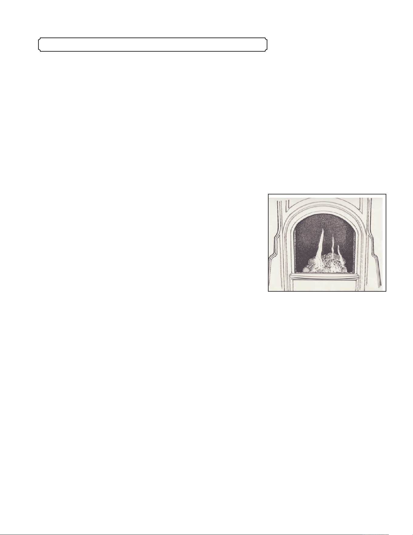
CHECK THE PILOT FLAME AND GAS LOG FLAMES
PERIODICALLY
The flame pattern should be relatively even. One of the pilot
flames should hit the thermocouple and the middle flame should
angle up toward the main burner pan at the right front corner. Black
carbon deposits on the logset are common, especially in LP-burning
stoves. Excessive loose build-up may have an impact on flame
appearance. See “Cleaning the inside of the firebox” for cleaning
instructions.
CLEANING THE GLASS
Do not clean the glass when it is hot. Always allow it to cool to
room temperature.
It will be necessary to clean the ceramic glass occasionally. It is
normal for condensation to form on the inside of the glass during a
cold start-up. Sometimes dust or lint clings to the condensation.
Residue from the initial paint curing inside the firebox can also leave
a residue on the inside of the glass.
We recommend that you clean the glass after the first couple
weeks of use. After the initial cleaning, the inside of the glass should
require cleaning no more than once or twice a year.
To clean the glass, use a mild glass cleaner and a soft cloth. Do
not use abrasive cleaners. Lift the front casting up, and pull the
bottom of the casting out from the Fireplace. Remove the glass front
by rotating the two spring loaded clips that hold the frame in place.
WARNING: Do not strike the glass front. Do not operate the
Mini Franklin Gas Stove with the glass front removed, cracked,
or broken. Replacement of the glass front should be done by a
licensed or qualified person. Do not use substitute materials
when replacing the front glass and frame assembly.
------------------------------------------------------------------------------------------------------------------------------------------------------------------------------------------------------ 25
-------------------------------------------------------------------------------------------------------------------------------------------------------------------- Routine Maintenance
19. ROUTINE MAINTENANCE
When theMini is operating properly, the
flame pattern will look approximately like
the drawing above.
------------------------------------------------------------------------------------------------------------------------------------------------------------------------------------------------------ 26
Use only the correct Woodstock Soapstone Company part
#G-140 Robax Ceramic Glass/Frame Assembly.
If the ceramic front glass becomes cracked or damaged, follow
the instructions below to remove the frame and damaged glass.
INSTRUCTIONS TO CLEAN, REMOVE OR REPLACE
GLASS FRONT:
The glass front on the Franklin Gas Stove consists of a fully
gasketed piece of ceramic glass, fastened with RTV Silicone adhesive
to a steel frame. If glass needs cleaning, use regular glass cleaner or,
for stubborn film,we offer a gas window cleaner. Do not use abrasive
cleaners. Never clean the glass when the glass is hot.
To replace the glass front and frame:
(1)Remove the front casting. Lift up the front casting, and swing the
bottom out. (See illustration 19.2.)
(2)Remove the two screws that hold the glass frame in place. (See
illustration 19.3.)
(3) Lift frame and glass out of Glass Window Retainer.
(4) Insert new or replacement frame and glass into Glass Window
retainer. The Glass Frame will line up with the edge of the
Firebox Frame. Keep the edges properly aligned to achieve the
best seal.
(5) Screw the new frame in place.
(6) Replace front casting. Slide top tab up under the top frame, and
then swing the bottom in behind the arched retaining rail.
CLEANING THE INSIDE OF THE FIREBOX
The firebox should be cleaned annually. Follow these steps:
1. Turn off gas supply.
2. Remove glass front (See illustration 19.2/3.).
3. The logset and burner are fragile and must be handled with
care. A soft bristle brush may be used delicately to remove
any dust or lint or loose black carbon deposits which may
accumulate. Do not use a vacuum on the logs.or ember bed.
4. Vacuum the inside of the firebox thoroughly.
5. Check that all gas ports are clear.
5. If glass needs cleaning, use regular glass cleaner or, for
stubborn film,we offer a gas window cleaner. Do not use
abrasive cleaners. Never clean the glass when the glass is
hot.
6. Replace log set and glass.
Illustration 19.2 To remove the
front casting, lift straight up under
the lip that extends over the top of
the glass.
Illustration 19.3 The glass front is
held in place by two screws
--------------------------------------------------------------------------------------------------------------------------------------------------------------- Routine Maintenance

------------------------------------------------------------------------------------------------------------------------------------------------------------------------------------------------------ 27
-------------------------------------------------------------------------------------------------------------------------------------------------------------------------- Annual Inspection
20. ANNUAL INSPECTION
ANNUAL INSPECTION
The Mini Franklin Gas Stove and venting system should be
inspected before use, and at least annually by a qualified field
service person to ensure that the flow of combustion and ventilation
air is not obstructed, the venting components are in good condition,
and that the appliance is working properly.
The technician should inspect and ensure that the lighting of the
main burner occurs within 4 seconds of the main gas valve opening.
Visual inspecion should match that outlined on page 25.
The technician should also check all gas tubes, connection, pipes
and other components for leaks.
Glass Cleaning
Clean the glass window with a suitable fireplace glass cleaner.
Abrasive cleaners must not be used. Be careful not to scratch the
glass when cleaning.
Annual Burner and Pilot Inspection and Cleaning
In order to properly clean the burner and pilot assembly, you will
have to turn off the gas supply to the appliance, and remove the front
casting, the glass front, the logs and ceramic burner assembly to
expose the pilot assembly.
Clean all foreign materials from the top of the burner and from the
pilot assembly with a soft brush. Vacuum any dust, lint or debris.
Check to be sure the burner and burner orifice are clean. If the pilot
orifice becomes plugged, disassembly may be required.
The technician should check to be sure that the flame safety
system works, and that the safety shutoff occurs within 30 seconds of
flame failure.
Annual Vent System Inspection
During the annual servicing, a qualified technician should inspect
the vent pipe to be sure that both the inside exhaust channel and the
outside air intake channel are clean and free of obstructions. All
parts should be checked for wear, corrosion, or deterioration. At the
end of inspection the venting components should be reassembled and
re-sealed according the the Simpson Dura-Vent instructions.
21. TROUBLESHOOTING – OWNER
These are troubleshooting problems you could check before
calling a technician. If these do not work, you must call in a qualified
gas technician.
PROBLEM SOLUTION
• Pilot will not light even though gas
control knob has been depressed and
turned repeatedly. Wait five minutes
for gas to dissipate, then do the
following before retrying.
• Pilot will not stay lit when first trying
to light it.
• Burner refuses to light, pilot is
working.
• Burner flame too low.
• Glass has white residue on inside.
1. Confirm that you are following the pilot lighting
instructions on page 21.
2. Make certain the gas supply is turned on.
3. If you are using propane, make sure tank is not too low.
(Under 20%)
4. Verify the ignitor wire is properly connected and
undamaged.
5. The ignitor spark may be checked visually at the right
front of the firebox with the logset removed.
1. Gas control knob not held down long enough for
thermocouple to heat up to keep pilot gas valve
turned on. (About 10 seconds after being lit).
2. Pilot gas knob not fully depressed.
1. Turn left flame adjustment knob counterclockwise until
flames appear.
2. Be sure temperature set in remote control is higher than
room temperature; adjust flame height with remote, flame
adj. Knob, or switch on back of stove.
3. If options 1 and 2 have been checked turn off the pilot
immediately. Orifice or manifold may be obstructed. Turn
the left flame adjustment knob to “off” and call a
qualified technician to remove either part and clear
obstruction.
1. Flame adjustment knob set at “LO”, Turn knob counter-
clockwise to increase.
2. Check vent pipe for possible blockage or loose
connections.
3. Call a qualified technician to check gas pressures.
1. Usual causes are contaminants in the combustion air.
Contaminants (called aldehydes) could be from garden
fertilizers or sprays, paint, any dust that is combustible.
-------------------------------------------------------------------------------------------------------------------------------------------------------------- Troubleshooting - Owner
------------------------------------------------------------------------------------------------------------------------------------------------------------------------------------------------------ 28

------------------------------------------------------------------------------------------------------------------------------------------------------------------------------------------------------ 29
-------------------------------------------------------------------------------------------------------------------------------------------------------------- Troubleshooting - Owner
PROBLEM SOLUTION
• Glass has white residue on inside
(continued)
• Glass has brown residue inside.
• Pungent odor.
• Soot accumulating up on walls or
furniture.
• If you have a Carbon Monoxide (CO)
sensor alarm, and it sounds.
2. Contaminants from paints or sealants used in
manufacturing the Fireplace. Clean with glass cleaner.
1. Over long periods of time (months), this may occur if
you are burning LP gas because it has more impurities
than natural gas. You will need to clean the glass more
often.
2. This can result rapidly if the flame is not properly
adjusted or there are other conditions that generate soot.
Adjustments should be made by a service technician.
1. Confirm pressure relief lids on top of and at the rear of
firebox are properly seated.
2. Partial burning of aldehydes (See “Glass has white
residue...” immediately above).
3. This condition may mean that carbon monoxide is
present.
4. Call gas technician to check gas connection and
installation.
Note: During the first few days of operation, there will be
an odor generated by the curing process. This is normal
and will abate.
1. Your gas Fireplace and venting system are sealed so
that it is virtually impossible for soot to come from
them. The most common source for this complaint turns
out to be from burning candles.
2. If you do not ever burn candles or do not have other
open flames, check for the presence of soot in your
Fireplace's firebox. If there is, look for a gasket leak
around the glass or where the vent pipe exits the
Fireplace. If there is a leak, there would likely be soot
evident in the area of the leak.
1. Incomplete or interrupted combustion of aldehydes
a.Ventilate room until aldehydes are all burned off, that
is, until the pungent odor is gone.
b. A gas technician should check gas connection and
installation.

------------------------------------------------------------------------------------------------------------------------------------------------------------------------------------------------------ 30
----------------------------------------------------------------------------------------------------------------------------------------------------------------------------------------- Warranty
Your Woodstock Soapstone Gas Fireplace has been carefully tested and
inspected prior to shipment to you. We take pride in every Fireplace we build but
our greatest satisfaction comes from our customers' continued happiness with
their Woodstock Soapstone Stoves. In addition to this limited warranty, you have
our assurance that we will be here to assist you in the installation, operation and
maintenance of your Woodstock Soapstone Stove for the life of the Fireplace. Our
customer service team is always happy to answer your questions.
Should you discover a defect, please call us for instruction about return and
replacement of the defective part. We will replace free of cost any part that is
defective in material or workmanship for one year from date of shipment. If you
take delivery during the late spring or summer, we will extend the warranty start
date to Thanksgiving of that year. If you find that you will be starting up your
Fireplace later than Thanksgiving, please let us know by calling or writing us and
giving us your projected installation and start up date. We will then confirm to
you, in writing, an extended warranty expiration date.
We further warrant that each Fireplace is exactly as we have represented
it. If you
are not completely satisfied with the appearance, quality or performance of your
Fireplace, you may return it within 30 days of delivery.
If your Fireplace is shipped by common carrier, it is insured against damage in
transit. We will repair or replace any Fireplace damaged in transit. Please inspect
your Fireplace carefully on receipt and report any damage to us within three days
of receipt.
This Warranty does not cover damage caused by abuse or neglect or if your
Fireplace was installed or used contrary to the instructions in your owner's
manual.
Woodstock Soapstone Company employees have no authority to offer any
warranty or remedy that varies from those covered here. This Warranty is not
transferable.
Woodstock Soapstone Company will not be liable for incidental and
consequential damages. (This may not apply to you if you live in a state that does
not allow the exclusion of incidental and consequential damages).
This warranty gives you specific legal rights. You may have other rights which
vary from state to state.
This limited warranty is in strict accordance with the Moss-Magnuson
Warranty Act.
22. WARRANTY
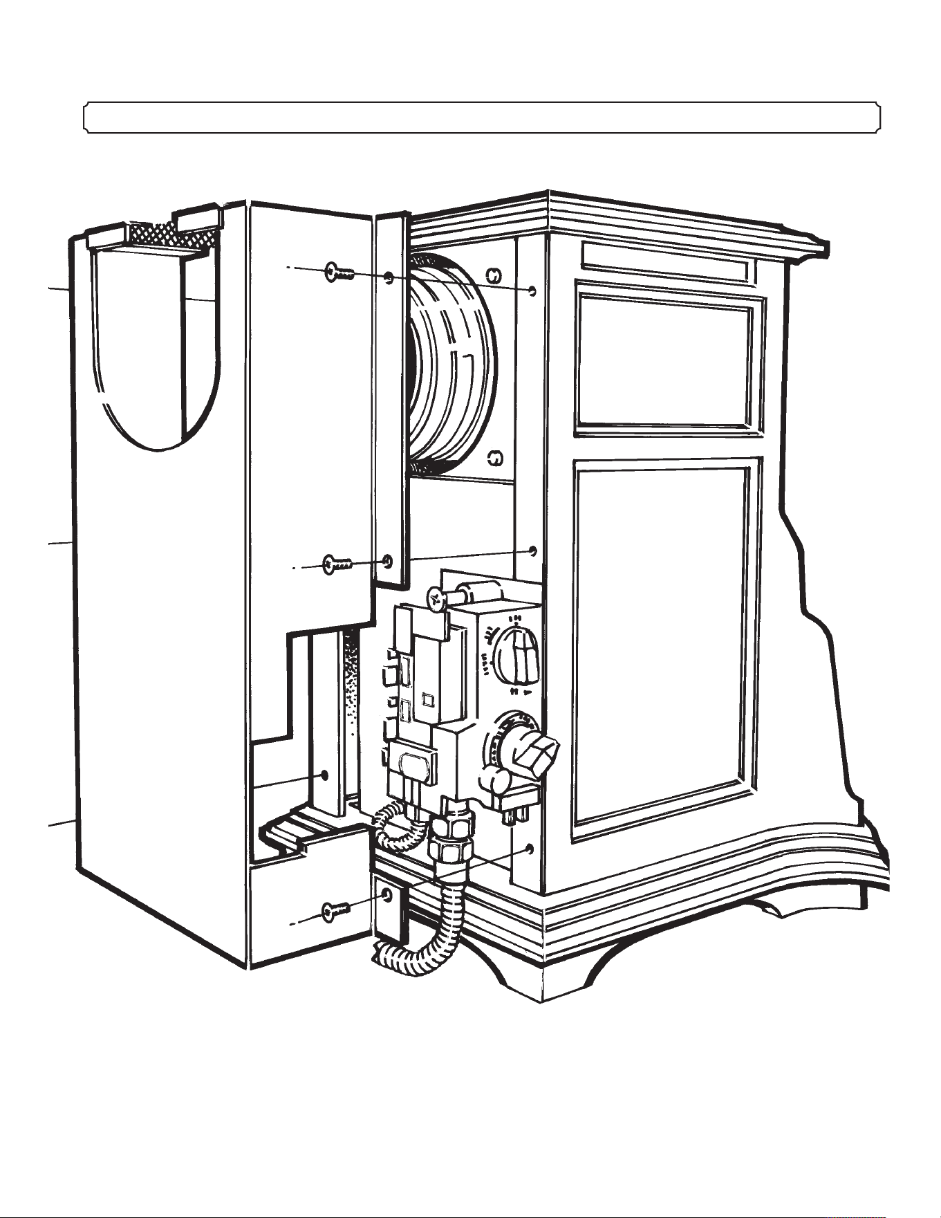
-------------------------------------------------------------------------------------------------------------------------------------------------------------------------------------------------------31
-------------------------------------------------------------------------------------------------------------------------------------------------------------------------------------- Appendix A
APPENDIX A. PARTS LIST AND REAR EXPLODED VIEW DIAGRAM

STONE
G-307 Top Soapstone
G-307A Front Soapstone (upper)
G-307B Front Soapstone (lower)
G-308A Right Side Soapstone (set)
G-308B Right Side Soapstone (set)
CAST IRON
G-301 Base
G-302 Left Side Wall
G-303 Right Side Wall
G-304 Top
G-305 Front
SHEET METAL
G-306 Firebox
G-310 Pressure Relief Door
G-312 Control Valve Mounting Plate
G-313 Outer DV Flue Adapter
G-314 Inner Sleeve Adapter
G-316 Window Frame
G-317 Top Stone Retainer
G-318 Top Heat Shield
G-319L Left Inner Side Shield
G-319R Right Inner Side Shield
G-320 Outer Side Heat Shield
G-321 Under Front Stone Retainer
G-322 Under Front Heat Shield
G-323 Over Front Heat Shield
G-324 Rear Panel with Grille
G-334 Bottom Heat Shield
MISCELLANEOUS
G-272/273 Pilot Assembly
G-20d/e/f Cap Orifice
G-325 Venturi Tube
G-326 Manifold Tube
G-330 Flex Line w/ Coupler
G-331 MF C1 Burner Pan Gasket
G-332a Ember Bed
G-332b Logset
G-333 Maxitrol Valve w/ 4 port option
G-336 Aluminum Port Plugs/Caps
G-337a LP-Minimum Rate Screw
G-337b NG-Minimum Rate Screw
GLASS
G-315 Glass
GASKET
G-2101 .375MX Fiberplass
G-2102 .187 Fiberglass Gasket
G-2103 .500 Fiberglass Gasket
G-2104 Flat Fiberglass Gasket
G-2105 Fiberglass Window Gasket
G-335 Pilot Assembly Gasket
ACCESSORIES
G-475 Remote Control (Maxitrol) & Receiver
G-476 Connecting Cable for Remote
Parts List
Mini Franklin Direct Vent Fireplace WARNING: Do not use substitute materials.
---------------------------------------------------------------------------------------------------------------------------------------------------------------------------------------- Parts List
To order parts, or for
information about parts or
service, please contact:
Woodstock Soapstone Company, Inc.
66 Airpark Road
West Lebanon, NH 03784
Tel: 800-866-4344
Fax: 603-298-5958
------------------------------------------------------------------------------------------------------------------------------------------------------------------------------------------------------ 32
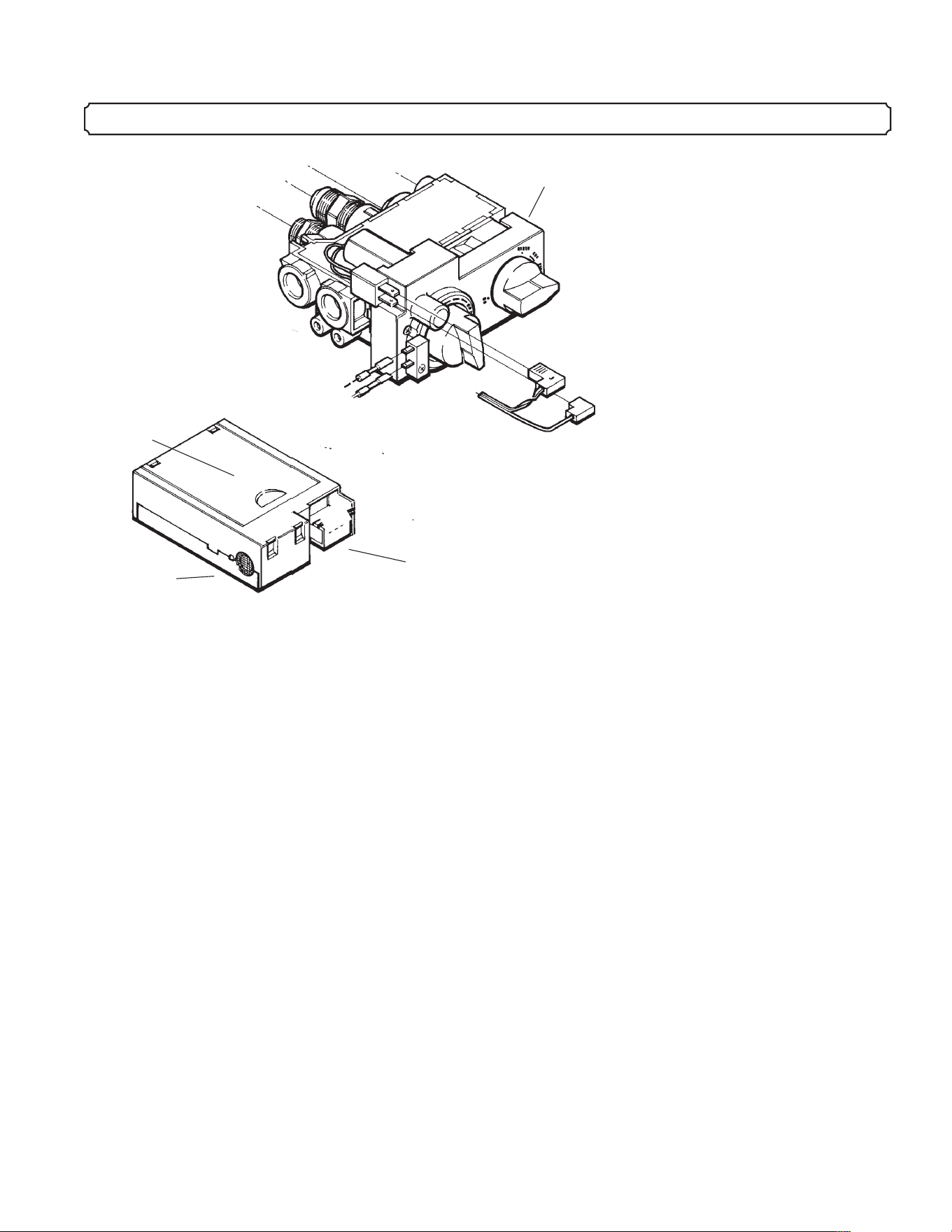
------------------------------------------------------------------------------------------------------------------------------------------------------------------------------------------------------- 33
------------------------------------------------------------------------------------------------------------------------------------------------------------------------------------ Appendix B
INSTALLATION INSTRUCTIONS
FOR OPTIONAL REMOTE CONTROL RECEIVER
If you choose the optional remote control unit, installation is as easy as
connecting the remote receiver and installing batteries in the transmitter
and receiver.
Note: Removal of front casting will make installation easier.
Connecting the Remote Receiver:
The remote control unit consists of two components: A) the remote transmitter
(requires one 9V battery); B) the remote receiver (requires four AA
batteries). Connection to the stove is made with a wiring harness also
included.
1.) Locate the wiring harness and the two “L” shaped blade connectors.
Connect the larger “L” shaped connector to the larger male blade
connector on the control valve as shown above. Connect the smaller “L”
shaped connector to the smaller male blade connector just below the larger
one.
2.) The two smaller female connectors on the wiring harness correspond to
the two male connectors located on the left side of the control valve next
to the left flame adjustment knob. Firmly attach the connectors on the
wiring harness to the control valve. It makes no difference which is on
top.
3.) Connect the wiring harness to the receiver. The wiring harness used to
connect the receiver has a large plastic plug on one end, and four smaller
connectors at the other. With the sensor opening facing toward you at the
APPENDIX B. WIRING DIAGRAM - REMOTE CONTROL UNIT
Remote Receiver
Gas Control
Valve
Sensor
Battery
Compartment
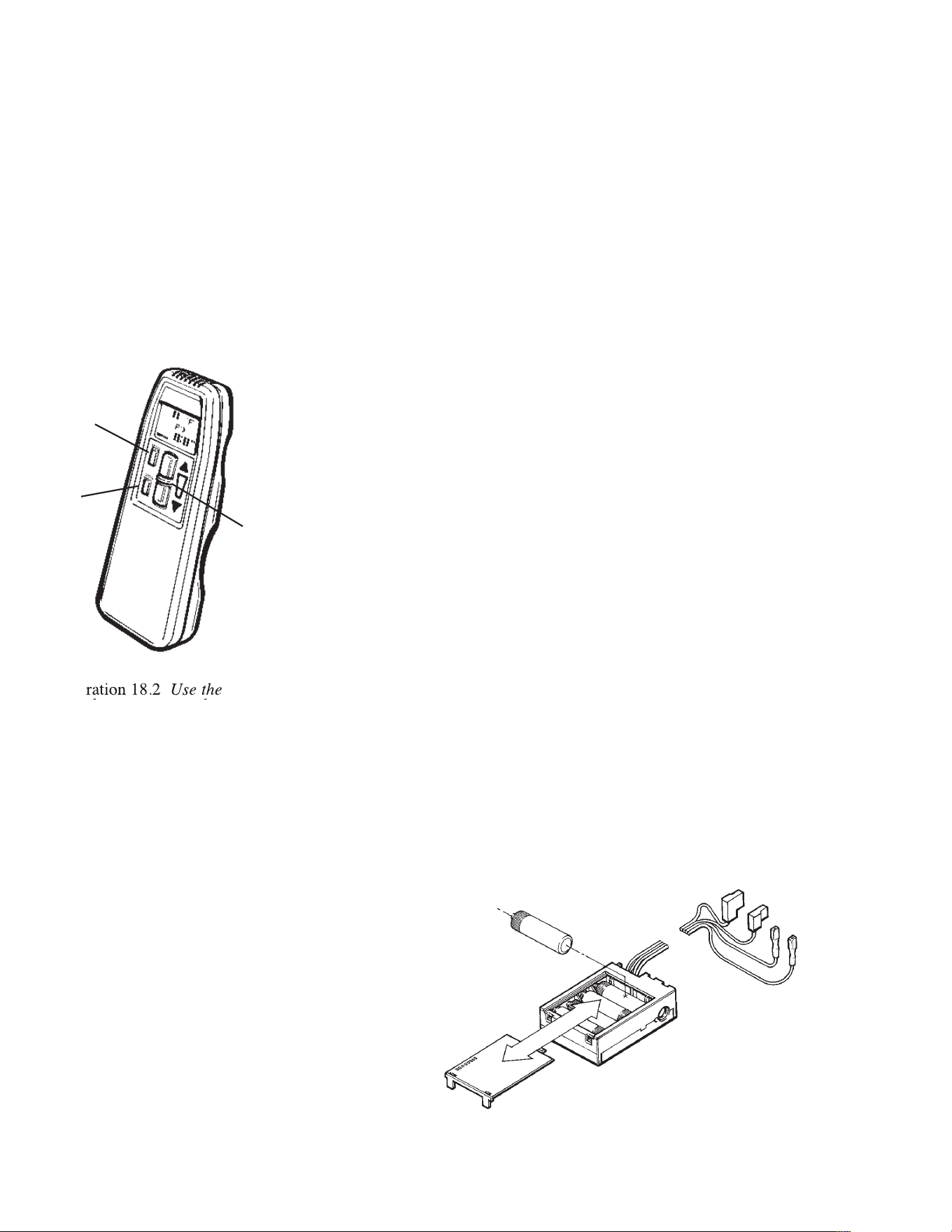
right end of the receiver, slide the large plastic plug (wire side
pointing up) firmly over the green tab on the right side of the
receiver. Note: Plug will fit securely in only one position.
4.) Install required batteries after all wire connections have been
made. The 9V battery for the transmitter is placed under the
sliding cover on the back. There is also a battery compartment
under the sliding cover on the receiver for the four AA batteries.
Alkaline batteries are recommended.
5.) Test your remote. The green LED on the receiver should light
when a signal is received from the transmitter. Try pressing the
large flame adjustment buttons on the transmitter. The left flame
adjustment knob on the control valve should turn up or down as
the buttons are pressed.
If the LED does not light or the flame adjustment knob does not
turn when buttons are pressed check all connections and/or
battery strength. The receiver sensor opening must be able to
receive sound waves, be sure it is not obstructed.
------------------------------------------------------------------------------------------------------------------------------------------------------------------------------------------------------ 34
------------------------------------------------------------------------------------------------------------------------------------------------------------------------------------- Appendix B
Illustration 18.2 Use the
large buttons to turn the
main burner ON or OFF
and control flame height.
Illustration 18.3
Remember that both the
remote control and the
remote receiver need
batteries!
ON/OFF
Switch
Flame Control
Auto
Timer