
Operator's Manual
CRRFTSMRN
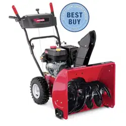
24" SNOW THROWER
Model No. 247.88957
CAUTION: Before using
this product, read this
manual and follow all
safety rules and operating
instructions.
o SAFETY
ASSEMBLY
OPERATION
MAINTENANCE
PARTS LIST
o ESPANOL
Sears, Roebuck and Co., Hoffman Estates, IL 60179, U.S.A.
Visit our website: www.craftsman.com FORMNO.769-05095
12/29/2009
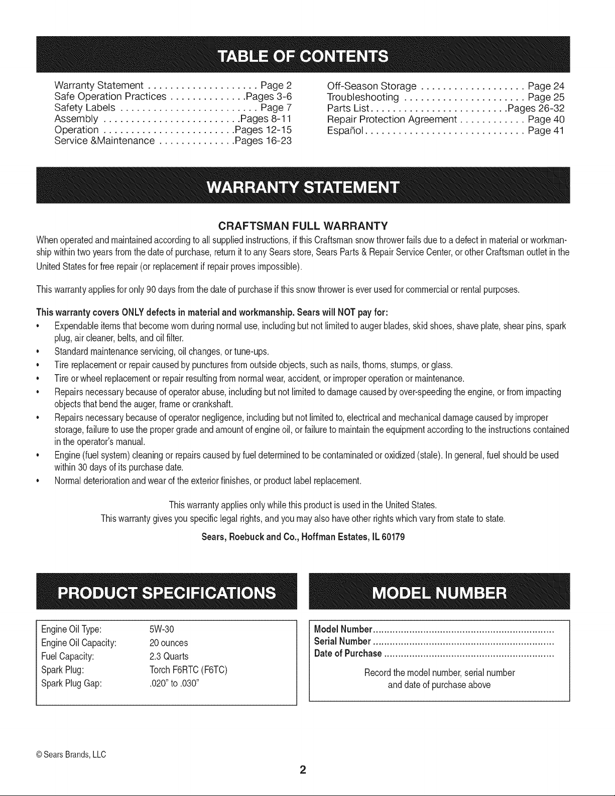
WarrantyStatement.................... Page2
SafeOperationPractices.............. Pages3-6
SafetyLabels......................... Page7
Assembly......................... Pages8-11
Operation........................ Pages12-15
Service&Maintenance.............. Pages16-23
Off-SeasonStorage................... Page24
Troubleshooting...................... Page25
PartsList......................... Pages26-32
RepairProtectionAgreement............ Page40
Espa_ol............................. Page41
CRAFTSMANFULLWARRANTY
Whenoperatedandmaintainedaccordingtoallsuppliedinstructions,ifthisCraftsmansnowthrowerfailsduetoadefectinmaterialorworkman-
shipwithintwoyearsfromthedateofpurchase,returnittoanySearsstore,SearsParts&RepairServiceCenter,orotherCraftsmanoutletinthe
UnitedStatesforfreerepair(orreplacementifrepairprovesimpossible).
Thiswarrantyappliesforonly90daysfromthedateofpurchaseifthissnowthroweriseverusedforcommercialorrentalpurposes.
Thiswarranty coversONLYdefects in material andworkmanship. Sears will NOTpay for:
• Expendableitemsthatbecomewornduringnormaluse,includingbutnot limitedto augerblades,skidshoes,shaveplate, shearpins,spark
plug,aircleaner,belts,andoilfilter.
• Standardmaintenanceservicing,oilchanges,or tune-ups.
Tire replacementor repaircausedby puncturesfromoutsideobjects,suchas nails,thorns,stumps,or glass.
• Tireor wheelreplacementor repairresultingfrom normalwear,accident,orimproperoperationor maintenance.
Repairsnecessarybecauseof operatorabuse, includingbutnot limitedto damagecausedby over-speedingthe engine,or from impacting
objectsthat bendthe auger,frameor crankshaft.
• Repairsnecessarybecauseof operatornegligence,includingbut not limitedto,electricaland mechanicaldamagecausedby improper
storage,failureto usethe propergradeandamountof engineoil, or failureto maintainthe equipmentaccordingto the instructionscontained
inthe operator'smanual.
• Engine(fuelsystem)cleaningor repairscausedbyfuel determinedto becontaminatedoroxidized(stale).In general,fuel shouldbe used
within30 daysof itspurchasedate.
Normaldeteriorationandwearof the exteriorfinishes,or productlabelreplacement.
Thiswarrantyappliesonly whilethisproductis usedinthe UnitedStates.
Thiswarrantygivesyou specificlegal rights,andyou mayalso haveotherrightswhichvaryfromstateto state.
Sears, Roebuck and Co., Hoffman Estates, IL 60179
EngineOilType: 5W-30
EngineOilCapacity: 20ounces
FuelCapacity: 2.3Quarts
SparkPlug: TorchF6RTC(F6TC)
SparkPlugGap: .020"to .030"
Model Number.................................................................
Serial Number .................................................................
Dateof Purchase.............................................................
Recordthe modelnumber,serialnumber
anddateof purchaseabove
© Sears Brands,LLC
2
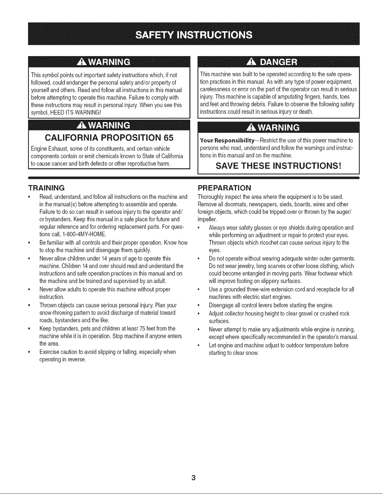
Thissymbolpointsout importantsafetyinstructionswhich,if not
followed,couldendangerthepersonalsafetyand/orpropertyof
yourselfand others. Readandfollowall instructionsin this manual
beforeattemptingto operatethismachine.Failureto complywith
theseinstructionsmay resultin personalinjury.Whenyou seethis
symbol,HEEDITSWARNING!
CALIFORNIA PROPOSITION 65
EngineExhaust,someof itsconstituents,andcertainvehicle
componentscontainoremitchemicalsknownto Stateof California
to causecancerandbirthdefectsorotherreproductiveharm,
Thismachinewasbuiltto beoperatedaccordingto the safeopera-
tion practicesinthis manual.As withanytypeof powerequipment,
carelessnessor error on the partof the operatorcan resultin serious
injury.Thismachineis capableof amputatingfingers,hands,toes
andfeetandthrowingdebris.Failureto observethe followingsafety
instructionscouldresultin seriousinjuryor death.
Your Responsibility--Restrict the useof this powermachineto
personswho read,understandandfollowthewarningsand instruc-
tionsin thismanualand on the machine,
SAVE THESE INSTRUCTIONS!
TRAiNiNG
• Read,understand,and followall instructionson the machineand
in themanual(s)beforeattemptingto assembleandoperate.
Failureto do socan resultin serious injuryto the operatorand/
orbystanders.Keepthis manualin a safe placeforfuture and
regularreferenceandfor orderingreplacementparts. Forques-
tionscall,1-800-4MY-HOME.
• Befamiliarwith all controlsandtheir properoperation.Knowhow
to stopthe machineanddisengagethemquickly.
Neverallowchildrenunder 14 yearsof age to operatethis
machine.Children14andover shouldreadandunderstandthe
instructionsand safe operationpracticesin this manualandon
the machineandbe trainedand supervisedby anadult.
Neverallowadultsto operatethis machinewithoutproper
instruction.
• Thrownobjectscan causeseriouspersonalinjury. Planyour
snow-throwingpatternto avoiddischargeof materialtoward
roads,bystandersandthe like.
Keepbystanders,pets and childrenat least75feetfromthe
machinewhile itisinoperation.Stopmachineifanyoneenters
the area.
Exercisecautionto avoidslippingor falling,especiallywhen
operatingin reverse.
PREPARATION
Thoroughlyinspecttheareawherethe equipmentis to beused.
Removeall doormats,newspapers,sleds,boards,wires and other
foreignobjects,whichcouldbe trippedoveror thrownby the auger/
impeller.
Alwayswear safetyglassesor eyeshieldsduringoperationand
while performingan adjustmentor repairto protectyoureyes.
Thrownobjectswhichricochetcancauseseriousinjuryto the
eyes.
Donot operatewithoutwearingadequatewinteroutergarments.
Donot wearjewelry,long scarvesor otherlooseclothing,which
could becomeentangledin movingparts.Wearfootwearwhich
will improvefootingonslipperysurfaces.
Usea groundedthree-wireextensioncordand receptaclefor all
machineswith electricstartengines.
Disengageall controlleversbeforestartingthe engine.
Adjustcollectorhousingheightto cleargravelorcrushedrock
surfaces.
Neverattemptto makeanyadjustmentswhileengineis running,
exceptwherespecificallyrecommendedinthe operator'smanual.
Letengineandmachineadjustto outdoortemperaturebefore
startingto clearsnow.
3
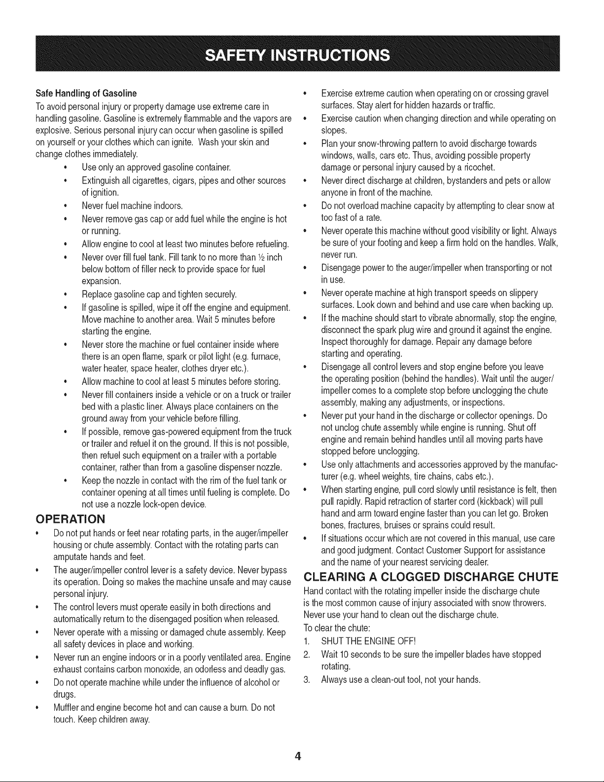
Safe Handling of Gasoline
Toavoidpersonalinjuryor propertydamageuseextremecare in
handlinggasoline.Gasolineis extremelyflammableandthe vaporsare
explosive.Seriouspersonalinjurycan occurwhengasolineis spilled
onyourselfor yourclotheswhichcan ignite.Washyour skinand
changeclothesimmediately.
• Useonly an approvedgasolinecontainer.
• Extinguishall cigarettes,cigars,pipesand other sources
of ignition.
• Neverfuelmachineindoors.
• Neverremovegas capor add fuel whilethe engineis hot
or running.
• Allowengineto coolat leasttwo minutesbeforerefueling.
• Neveroverfill fueltank. Filltank to no morethan1/2inch
belowbottomof filler neckto providespacefor fuel
expansion.
• Replacegasolinecap andtightensecurely.
• If gasolineis spilled,wipeit off the engineand equipment.
Movemachineto anotherarea.Wait5 minutesbefore
startingthe engine.
• Neverstorethe machineor fuel containerinsidewhere
thereis anopenflame,sparkor pilotlight (e.g.furnace,
waterheater,spaceheater,clothesdryer etc.).
• Allowmachineto cool at least5 minutesbeforestoring.
• Neverfill containersinsidea vehicleor ona truckor trailer
bedwitha plasticliner.Alwaysplacecontainersonthe
groundawayfromyourvehiclebeforefilling.
• If possible,removegas-poweredequipmentfromthetruck
ortrailerand refuelit on the ground.If this is not possible,
then refuelsuch equipmenton a trailerwith a portable
container,ratherthan fromagasolinedispensernozzle.
• Keepthe nozzlein contactwith the rimof the fueltank or
containeropeningat alltimesuntil fuelingis complete.Do
notuse a nozzlelock-opendevice.
OPERATION
• Do not puthandsorfeetnear rotatingparts,in the auger/impeller
housingor chuteassembly.Contactwiththe rotatingpartscan
amputatehandsandfeet.
• Theauger/impellercontrolleveris a safetydevice.Neverbypass
itsoperation.Doingso makesthe machineunsafeand may cause
personalinjury.
• Thecontrol leversmustoperateeasilyin bothdirectionsand
automaticallyreturnto the disengagedpositionwhenreleased.
• Neveroperatewith a missingor damagedchuteassembly.Keep
all safetydevicesin placeand working.
• Neverrunan engine indoorsor ina poorlyventilatedarea. Engine
exhaustcontainscarbonmonoxide,an odorlessanddeadlygas.
• Do notoperatemachinewhileunderthe influenceof alcoholor
drugs.
• Mufflerandenginebecomehotandcan causea burn.Do not
touch.Keepchildrenaway.
• Exerciseextremecautionwhenoperatingon or crossinggravel
surfaces.Stay alertfor hidden hazardsor traffic.
• Exercisecautionwhenchangingdirectionandwhileoperatingon
slopes.
• Planyoursnow-throwingpatternto avoiddischargetowards
windows,walls,carsetc. Thus,avoidingpossibleproperty
damageor personalinjurycausedby a ricochet.
• Neverdirect dischargeat children,bystandersand petsor allow
anyoneinfrontof the machine.
• Donot overloadmachinecapacityby attemptingto clearsnowat
too fastof a rate.
• Neveroperatethis machinewithoutgoodvisibilityorlight.Always
be sureof yourfootingand keepa firmholdon the handles.Walk,
neverrun.
• Disengagepowerto theauger/impellerwhentransportingor not
in use.
• Neveroperatemachineat high transportspeedson slippery
surfaces.Lookdownand behindand usecare whenbackingup.
• If the machineshouldstart to vibrateabnormally,stopthe engine,
disconnectthe sparkplugwire andgroundit againstthe engine.
Inspectthoroughlyfor damage.Repairanydamagebefore
startingandoperating.
• Disengageall controlleversand stop enginebeforeyouleave
the operatingposition(behindthe handles).Wait untilthe auger/
impellercomesto a completestopbeforeuncloggingthechute
assembly,makingany adjustments,or inspections.
• Neverput yourhand in the dischargeor collectoropenings.Do
not unclogchuteassemblywhileengineis running.Shutoff
engineand remainbehindhandlesuntilall movingpartshave
stoppedbeforeunclogging.
• Useonly attachmentsand accessoriesapprovedby the manufac-
turer (e.g.wheelweights,tire chains,cabsetc.).
• Whenstartingengine,pullcord slowlyuntilresistanceis felt, then
pull rapidly.Rapidretractionof startercord(kickback)will pull
handandarmtowardenginefasterthan youcan let go. Broken
bones,fractures,bruisesor sprainscould result.
• If situationsoccur whichare notcoveredin this manual,use care
andgoodjudgment.ContactCustomerSupportfor assistance
andthe nameof your nearestservicingdealer.
CLEARING A CLOGGED DISCHARGE CHUTE
Handcontactwith the rotatingimpellerinsidethe dischargechute
is the mostcommoncauseof injuryassociatedwith snowthrowers.
Neveruse yourhandto cleanout thedischargechute.
Toclear thechute:
1. SHUTTHEENGINEOFF!
2. Wait 10secondsto be surethe impellerbladeshavestopped
rotating.
3. Alwaysusea clean-outtool, not yourhands.
4
MAINTENANCE & STORAGE
• Nevertamperwithsafetydevices.Checktheirproperoperation
regularly.Referto the maintenanceand adjustmentsectionsof
thismanual.
• Beforecleaning,repairing,or inspectingmachinedisengageall
controlleversandstopthe engine.Wait untilthe auger/impeller
cometo a completestop.Disconnectthe sparkplugwireand
groundagainsttheengineto preventunintendedstarting.
Checkboltsand screwsfor propertightnessat frequentintervals
to keepthe machineinsafeworkingcondition.Also, visually
inspectmachinefor anydamage.
Do notchangetheenginegovernorsettingor over-speedthe
engine.Thegovernorcontrolsthe maximumsafeoperatingspeed
of the engine.
Snowthrowershaveplatesand skid shoesare subjectto wear
anddamage.Foryoursafetyprotection,frequentlycheckall
componentsand replacewithoriginalequipmentmanufacturer's
(OEM)partsonly."Useof partswhichdo not meetthe original
equipmentspecificationsmayleadto improperperformanceand
compromisesafety!"
Checkcontrolleversperiodicallyto verifytheyengageanddisen-
gageproperlyand adjust,if necessary.Referto the adjustment
sectioninthisoperator'smanualfor instructions.
Maintainor replacesafetyandinstructionlabels,as necessary.
• Observeproperdisposallawsand regulationsfor gas,oil,etc. to
protectthe environment.
Priorto storing,run machinea few minutestoclear snowfrom
machineand preventfreezeup of auger/impeller.
Neverstorethe machineorfuel containerinsidewherethereisan
openflame,spark or pilot lightsuch as a waterheater,furnace,
clothesdryer etc.
Alwaysreferto the operator'smanualfor properinstructionson
off-seasonstorage.
Checkfuelline,tank, cap,andfittingsfrequentlyfor cracksor
leaks.Replaceif necessary.
Do notcrankenginewithsparkplugremoved.
Accordingto the ConsumerProductsSafetyCommission(CPSC)
andthe U.S.EnvironmentalProtectionAgency(EPA),this product
hasan AverageUsefulLifeof seven(7) years,or 60 hoursof
operation.At the endof theAverageUsefulLifehavethe machine
inspectedannuallybyan authorizedservicedealerto ensurethat
allmechanicaland safetysystemsare workingproperlyand not
wornexcessively.Failureto do so can resultinaccidents,injuries
ordeath.
DO NOT MODIFY ENGINE
Toavoidseriousinjuryor death,do not modifyengineinany way.
Tamperingwiththe governorsettingcanlead to a runawayengineand
causeit to operateat unsafespeeds.Nevertamperwithfactory setting
of enginegovernor.
NOTICE REGARDING EMiSSiONS
Engineswhich are certifiedtocomplywith Californiaand federal
EPAemissionregulationsfor SORE(SmallOff RoadEquipment)are
certifiedto operateon regularunleadedgasoline,and mayinclude
the followingemissioncontrol systems:EngineModification(EM),
OxidizingCatalyst(OC), SecondaryAir Injection(SAI)and ThreeWay
Catalyst(TWO)if so equipped.
SPARK ARRESTOR
Thismachineisequippedwithaninternalcombustionengineand
shouldnotbe usedon or nearany unimprovedforest-covered,
brush-coveredor grass-coveredland unlessthe engine'sexhaust
systemisequippedwith a sparkarrestermeetingapplicablelocalor
statelaws(if any)
Ifa sparkattesteris used,it shouldbemaintainedin effectiveworking
orderby theoperator.Inthe Stateof Californiathe aboveis required
bylaw (Section4442of the CaliforniaPublicResourcesCode).Other
statesmayhavesimilarlaws. Federallawsapplyon federallands.
A sparkarresterfor the muffleris availablethroughyournearestSears
PartsandRepairServiceCenter.
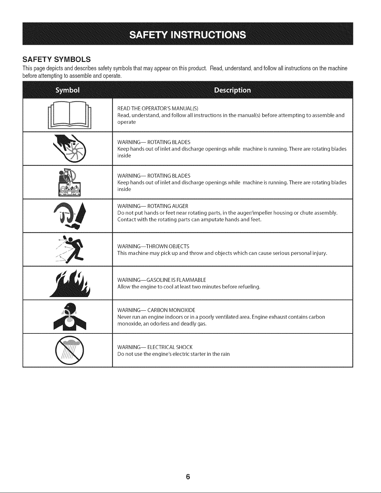
SAFETY SYMBOLS
Thispagedepictsanddescribessafetysymbolsthatmayappearonthisproduct. Read,understand,and followall instructionson the machine
beforeattemptingto assembleandoperate.
i
i
READ THE OPERATOR'S MANUAL(S)
Read, understand, and follow all instructions in the manual(s) before attempting to assemble and
operate
WARNING-- ROTATING BLADES
Keep hands out of inlet and discharge openings while machine is running. There are rotating blades
inside
WARNING-- ROTATING BLADES
Keep hands out of inlet and discharge openings while machine is running. There are rotating blades
inside
WARNING-- ROTATING AUGER
Do not put hands or feet near rotating parts, in the auger/impeller housing or chute assembly.
Contact with the rotating parts can amputate hands and feet.
WARNING--THROWN OBJECTS
This machine may pick up and throw and objects which can cause serious personal injury.
WARNING--GASOLINE IS FLAMMABLE
Allow the engine to cool at least two minutes before refueling.
WARNING-- CARBON MONOXIDE
Never run an engine indoors or in a poorly ventilated area. Engine exhaust contains carbon
monoxide, an odorless and deadly gas.
WARNING-- ELECTRICAL SHOCK
Do not use the engine's electric starter in the rain
6
r
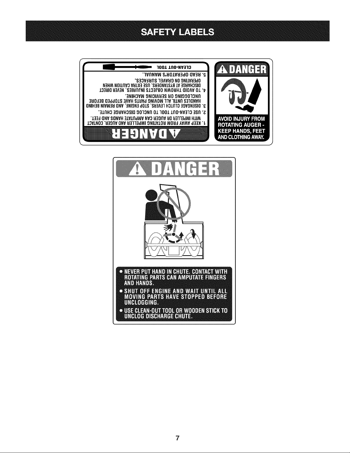
100/.LIIO-NV:IIO
"lVflNV_ S,UOIVU3dOQV3H"G
"S3OV_IJflS]3AVUONO9NIIV_J3dO
N3HMNOIIflVOVSIX] qsfl"S9]ONVIS181V]98VHOSIO
10381083A3N'S]IUflrNI SI03PgoNMOUHIQIOAV01 "_
"3NIHOV_ONIOIA83SUOONIOOO]ONfl
]UO_38O3ddOIS]AVHSlHPd9NIAOW11VlllNfl S]IQNVH
ONIH]8NIVW3UONV']NION]dOlS'88]A]1HOlnlo]9VON]SIO"8
"]lnHg ]gHVHOSIO9010Nfl01 1001 lflO-NP]lO ]Sfl "Z
"l]]d ONVSONVH]lPlnd_P NVOH3onvuo Hq]l]d_JIHIIM
IOVINO0"u39npONV_J3113dWI9NllVIOU_JOH_IVMV d]3H "L
7
NOTE:Referencesto rightorleft sideof the snowthrowerare
determinedfrombehindthe unit inthe operatingposition(standing
directlybehindthe snowthrower,facingthe handlepanel).
REMOVING FROM CARTON
1. Cut the cornersof thecarton and lay the sidesflat on the ground.
Removeand discard all packinginserts.
2. Movethe snowthrowerout of thecarton.
3. Makecertainthe carton has beencompletelyemptiedbefore
discardingit.
LOOSE PARTS
Tworeplacementaugershearpinsare includedinthe handlepanel.
Referto ReplacingShearPinsinthe Operationsectionfor more
informationregardingshearpin replacement.
ASSEMBLY
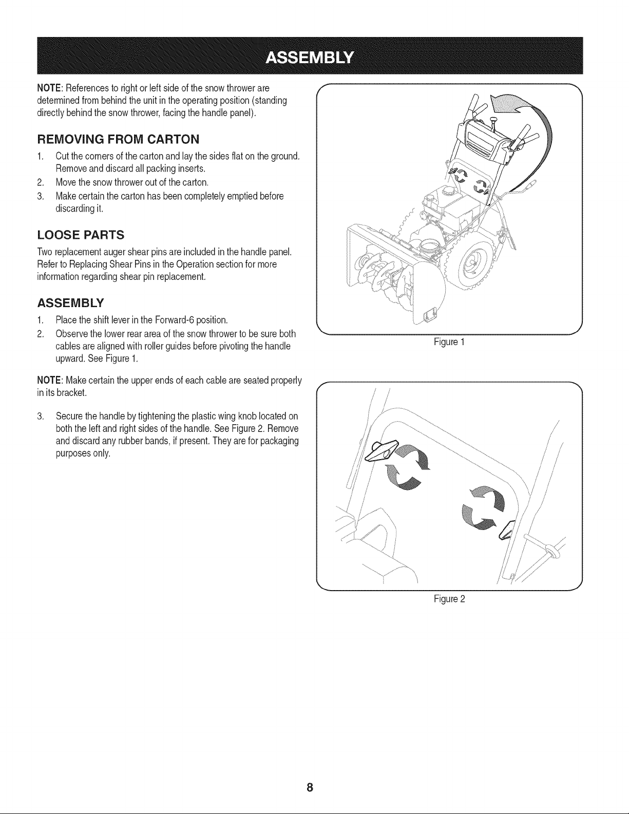
1. Placethe shiftleverin the Forward-6position.
2. Observethe lowerreararea of the snowthrowerto be sure both
cablesarealignedwith rollerguidesbeforepivotingthe handle
upward.See Figure1.
Figure1
NOTE:Makecertainthe upperends of eachcableare seatedproperly
in itsbracket.
.
Securethehandlebytighteningthe plasticwing knoblocatedon
boththe left andrightsidesof the handle.See Figure2. Remove
anddiscardany rubberbands,if present.They are for packaging
purposesonly.
f
!
/
/
/
Figure2
8
.
5.
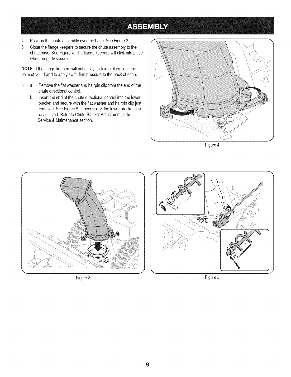
Positionthechuteassemblyoverthe base.See Figure3.
Closethe flangekeepersto securethechuteassemblyto the
chutebase.SeeFigure4. The flangekeeperswill click intoplace
whenproperlysecure.
NOTE:Ifthe flangekeeperswill noteasilyclickinto place,usethe
palmof yourhandto applyswift,firmpressureto the backof each.
.
a.
b.
Removetheflat washerand hairpinclip from the end of the
chutedirectionalcontrol.
Insertthe endof the chutedirectionalcontrolinto the lower
bracketand securewith the flat washerand hairpinclipjust
removed.See Figure5. If necessary,the lowerbracketcan
beadjusted.Referto ChuteBracketAdjustmentinthe
Service& Maintenancesection.
Figure4
f F
Figure3
\
J
Figure5
9
SET-UP
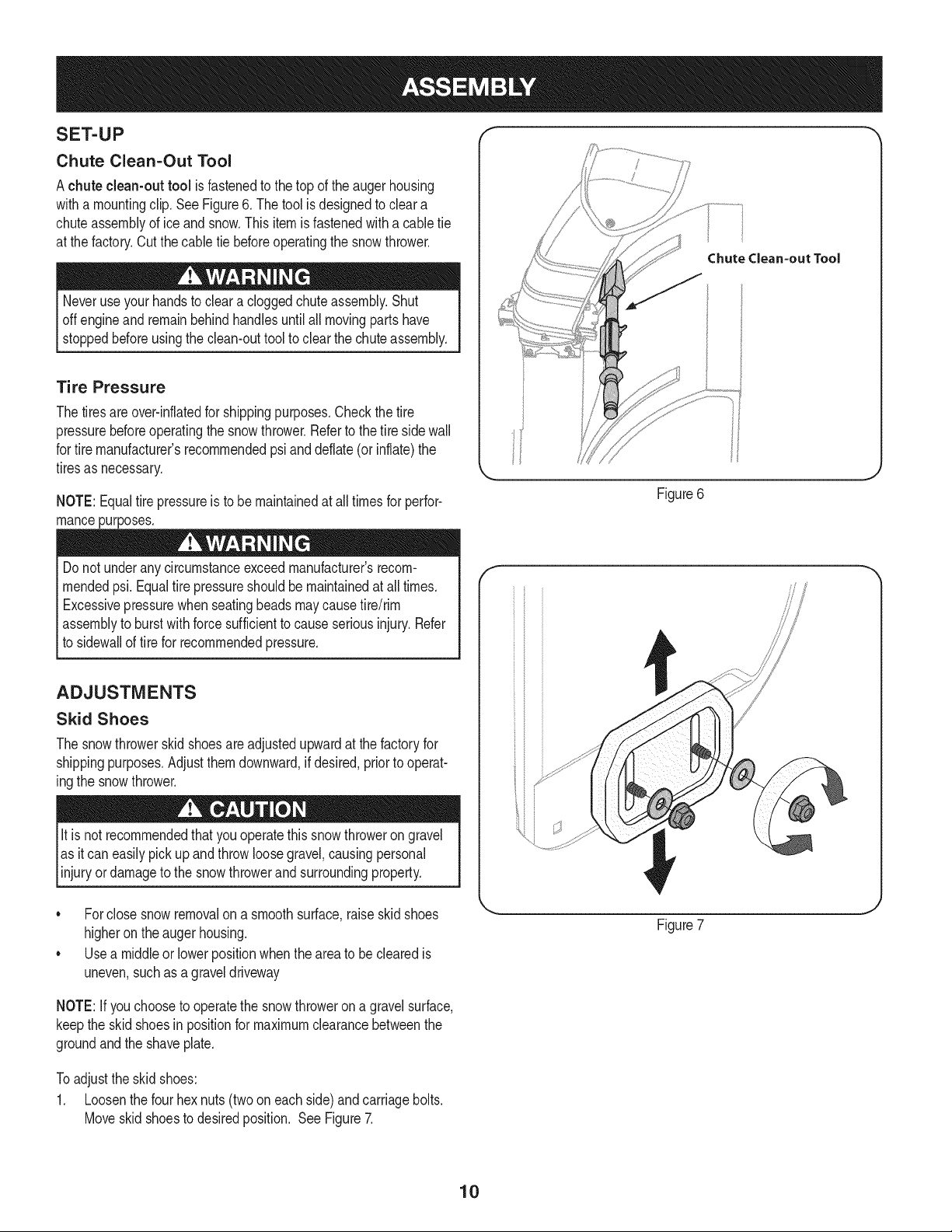
Chute Clean-Out Tool
Achute clean-out tool is fastenedto the top of the augerhousing
witha mountingclip.SeeFigure6. The tool is designedto cleara
chuteassemblyof ice andsnow.This item is fastenedwitha cabletie
at the factory.Cut thecable tie beforeoperatingthe snowthrower.
Neveruseyour handsto cleara cloggedchuteassembly.Shut
offengineand remainbehindhandlesuntilall movingpartshave
stoppedbeforeusingthe clean-outtool to clear thechute assembly.
Tire Pressure
Thetiresareover-inflatedfor shippingpurposes.Checkthetire
pressurebeforeoperatingthe snow thrower.Referto the tire sidewall
for tiremanufacturer'srecommendedpsiand deflate(or inflate)the
tiresas necessary.
NOTE:Equaltire pressureis to be maintainedat alltimesfor perfor-
mancepurposes.
Do not underanycircumstanceexceedmanufacturer'srecom-
mendedpsi. Equaltire pressureshouldbe maintainedat all times.
Excessivepressurewhenseatingbeadsmaycausetire/rim
assemblyto burstwithforcesufficientto causeseriousinjury. Refer
to sidewallof tirefor recommendedpressure.
ADJUSTMENTS
Skid Shoes
The snowthrowerskidshoesareadjustedupwardat thefactoryfor
shippingpurposes.Adjustthemdownward,ifdesired,priorto operat-
ingthe snowthrower.
It isnot recommendedthat youoperatethis snowthroweron gravel
as itcan easilypickup andthrowloosegravel,causingpersonal
njuryordamageto the snowthrowerand surroundng property.
• Forclosesnowremovalona smoothsurface,raiseskidshoes
higheronthe augerhousing.
Usea middleor lowerpositionwhentheareato be clearedis
uneven,suchas a graveldriveway
ChuteClean=outTool
Figure6
f
Figure7
NOTE:If youchooseto operatethe snowthroweron a gravelsurface,
keepthe skidshoesin positionfor maximumclearancebetweenthe
groundandthe shaveplate.
Toadjustthe skidshoes:
1. Loosenthe four hexnuts(twooneach side)andcarriagebolts.
Moveskidshoesto desiredposition. SeeFigure7.
10
2, Makecertain theentirebottomsurfaceof skidshoeis againstthe
groundto avoidunevenwearon the skid shoes,
3, Refightennutsandboltssecurely,
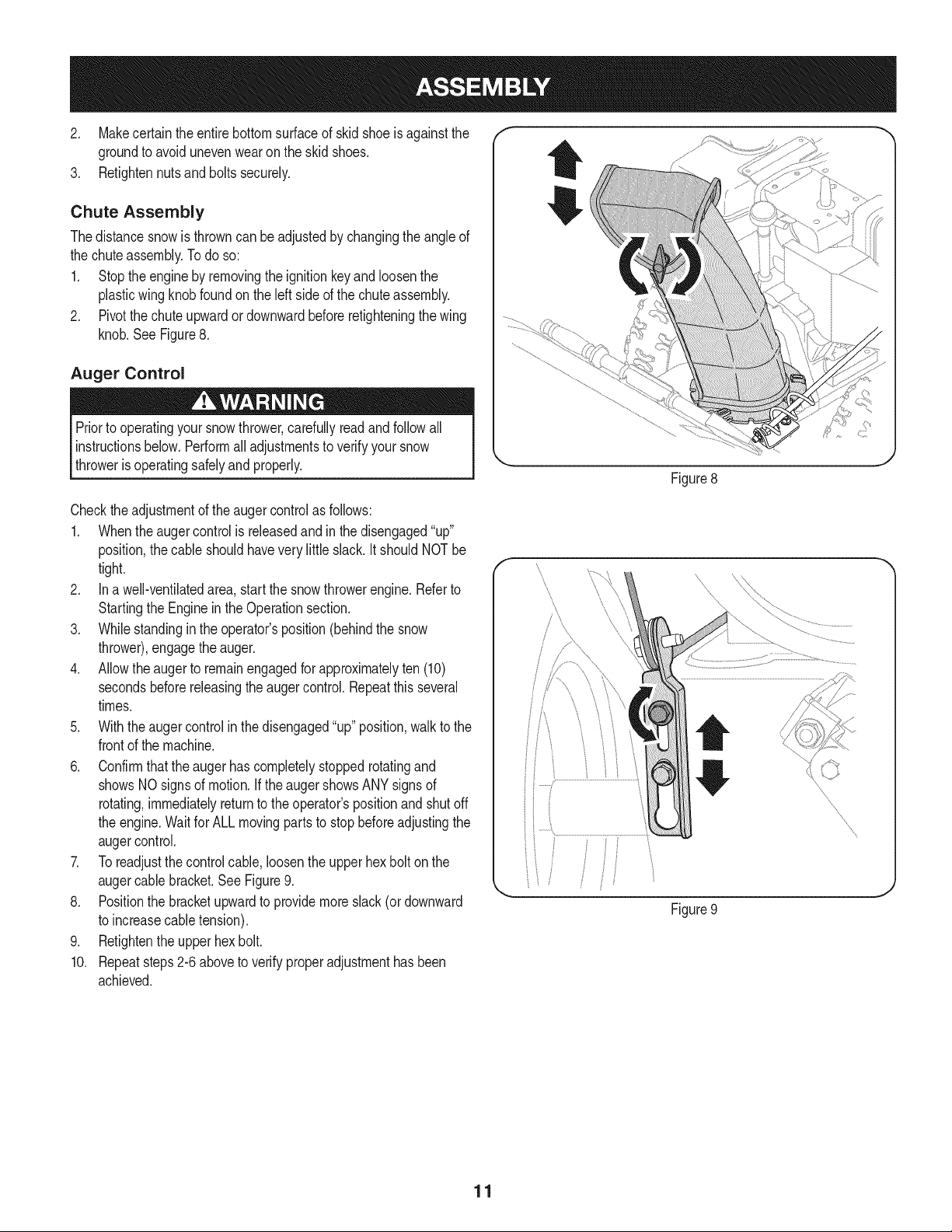
Chute Assembly
Thedistancesnowis throwncan beadjustedby changingthe angle of
the chuteassembly,Todo so:
1, Stopthe engineby removingthe ignitionkeyandloosenthe
plasticwingknobfoundonthe left sideof the chuteassembly.
2, Pivotthe chute upwardordownwardbeforeretighteningthewing
knob,See Figure8,
Auger Control
Priorto operatingyoursnowthrower,carefullyreadand follow all
instructionsbelow,Performall adjustmentsto verifyyour snow
throweris operatingsafelyand properly,
Figure8
Checktheadjustmentof the augercontrolas follows:
1. Whentheaugercontrolis releasedandin the disengaged"up"
position,the cableshouldhavevery little slack. It shouldNOTbe
tight.
2. In a well-ventilatedarea,start the snowthrowerengine.Referto
Startingthe Engineinthe Operationsection.
3. Whilestandingin the operator'sposition(behindthe snow
thrower),engagethe auger.
4. Allowtheauger to remainengagedfor approximatelyten (10)
secondsbeforereleasingthe augercontrol.Repeatthisseveral
times.
5. With theauger controlin thedisengaged"up" position,walkto the
frontof the machine.
6. Confirmthatthe augerhas completelystoppedrotatingand
showsNOsignsof motion.If the augershowsANYsignsof
rotating,immediatelyreturnto the operator'spositionandshutoff
the engine.Waitfor ALL movingparts to stop beforeadjustingthe
augercontrol.
7. Toreadjustthecontrolcable, loosentheupperhexbolt onthe
augercablebracket.SeeFigure9.
8. Positionthe bracketupwardto providemoreslack(or downward
to increasecabletension).
9. Retightenthe upperhex bolt.
10. Repeatsteps2-6 aboveto verifyproperadjustmenthasbeen
achieved.
11
f
Drive Control
ShiftLever
/
/
Auger Control
Gas Cap
Chute Assembly Oil Fill
\ \,
\
\
_ ChuteDirectionalControl
Clean Out
Tool
\
Augers
SkidShoe
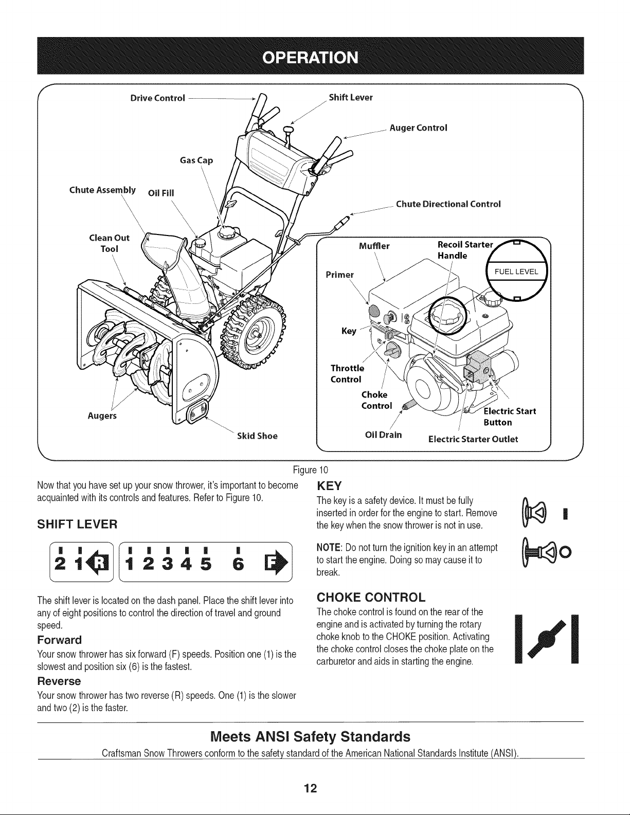
Nowthat youhavesetup yoursnowthrower,it'simportantto become
acquaintedwith itscontrolsand features.Referto Figure10.
SHIFT LEVER
Primer
Mumer Recoil Starter
_._andle
Key
Throttle
Control
Choke
Control
Oil Drain
:lectric Start
Button
Electric Starter Outlet
,.. j
Figure10
KEY
The keyis a safetydevice.It mustbefully
insertedin orderfor the engineto start. Remove
the keywhenthe snowthroweris not in use.
'
1 2345 6
NOTE: Donot turnthe ignitionkeyinan attempt
to startthe engine.Doingso may causeit to
break.
J
The shiftleveris locatedonthe dash panel.Placethe shift leverinto
anyof eight positionsto controlthe directionof travelandground
speed.
Forward
Yoursnowthrowerhas sixforward(F) speeds.Positionone(1)is the
slowestandpositionsix(6) is the fastest.
Reverse
Yoursnowthrowerhastwo reverse(R) speeds.One(1)is the slower
andtwo(2) is the faster.
CHOKE CONTROL
The chokecontrolis foundon the rearof the
engineand is activatedby turningthe rotary
chokeknobto the CHOKEposition.Activating
the chokecontrolclosesthe chokeplateon the
carburetorandaids in startingthe engine.
Meets ANSi Safety Standards
CraftsmanSnowThrowersconformto the safetystandardof the AmericanNationalStandardsInstitute(ANSI).
12
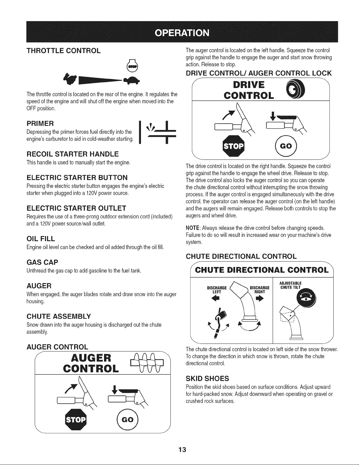
THROTTLE CONTROL
Thethrottlecontrolis locatedon the rearof the engine.It regulatesthe
speedof theengineandwill shutoff the enginewhenmovedintothe
OFFposition.
PRIMER I _TY-"-L
Depressingthe primerforcesfuel directlyintothe
engine'scarburetorto aid incold-weatherstarting.
RECOIL STARTER HANDLE
Thishandleis usedto manuallystartthe engine.
ELECTRIC STARTER BUTTON
Pressingthe electricstarterbuttonengagesthe engine'selectric
starterwhenpluggedintoa 120Vpowersource.
ELECTRIC STARTER OUTLET
Requiresthe useof athree-prongoutdoorextensioncord(included)
anda 120Vpowersource/walloutlet.
OIL FILL
Engineoil levelcan be checkedand oil addedthroughtheoil fill.
GAS CAP
Unthreadthe gascap to addgasolineto the fuel tank.
The augercontrolis locatedon the lefthandle.Squeezethe control
gripagainstthe handleto engagethe augerand startsnowthrowing
action.Releaseto stop.
DRIVE CONTROL/AUGER CONTROL LOCK
J DRIVE
CONTROL
The drivecontrolis locatedon the righthandle.Squeezethe control
gripagainstthe handleto engagethe wheeldrive.Releaseto stop.
The drivecontrolalso lockstheaugercontrolso youcan operate
the chutedirectionalcontrolwithoutinterruptingthe snowthrowing
process.If the augercontrolis engagedsimultaneouslywith the drive
control,the operatorcan releasethe augercontrol(onthe lefthandle)
andthe augerswill remainengaged.Releaseboth controlsto stop the
augersandwheeldrive.
NOTE:Alwaysreleasethedrivecontrolbeforechangingspeeds.
Failureto do so will result in increasedwearon yourmachine'sdrive
system.
CHUTE DIRECTIONAL CONTROL
_CHUTE DIRECTIONAL CONTROL
AUGER
Whenengaged,the auger bladesrotateand drawsnowintothe auger
housing,
CHUTE ASSEMBLY
Snowdrawninto theauger housingis dischargedout the chute
assembly.
AUGER CONTROL
/ AUGER
CONTROL
&
ADJUSTABLE
DISCHARGE CHUTETILTDISCHARGE
LEFT
#
_ J
The chute directional control is located on left side of the snow thrower,
Tochange the direction inwhich snow is thrown, rotate the chute
directional control.
SKID SHOES
Positionthe skidshoesbasedonsurfaceconditions.Adjustupward
for hard-packedsnow.Adjustdownwardwhenoperatingon gravelor
crushedrocksurfaces.
13
CLEAN-OUT TOOL
Neveruse yourhandsto cleara cloggedchute assembly.Shut
off engineandremainbehindhandlesuntilall movingpartshave
stoppedbeforeusingthe clean-outtoolto clear thechute assembly.
Thechuteclean-outtool is convenientlyfastenedto the rear of the
augerhousingwith a mountingclip. Shouldsnowandice become
lodgedin thechute assemblyduringoperation,proceedas followsto
safelycleanthechuteassemblyandchuteopening:
1. Releaseboththe AugerControland the DriveControl.
2. Stopthe engineby removingthe ignitionkey.
3. Removethe clean-outtoolfromthe clip whichsecuresit to the
rearof the augerhousing.
4. Use the shovel-shapedendof theclean-outtool to dislodgeand
scoopany snowand icewhichhasformedin and near thechute
assembly.
5. Refastenthe clean-outtool to the mountingclip onthe rearof
theaugerhousing,reinsertthe ignitionkeyandstartthe snow
thrower'sengine.
6. Whilestandingin the operator'sposition(behindthesnow
thrower),engagethe auger controlfora few secondsto clear any
remainingsnowand ice from thechute assembly.
BEFORE STARTING ENGINE
Read,understand,and followall instructionsandwarningson the
machineand in this manualbeforeoperating.
Oil
Theunit wasshippedwith oil in the engine.Checkoil levelbefore
eachoperationto ensureadequateoil inthe engine.Forfurther
instructions,refertothe stepson page16.
NOTE:Besureto checkthe engineon a levelsurfacewith the engine
stopped.
1. Removethe oil fillercap/dipstickandwipethe dipstickclean.
2. insertthe cap/dipstickintothe oil filler neck,butdo NOTscrewit
in.
3. Removethe oil fillercap/dipstick,ifthe levelislow,slowlyadd
oil (5%30, witha minimumclassificationof SF/SG)untiloil level
registersbetweenhigh (H) and low(L).
NOTE:Do notoverfill.Overfillingwithoil mayresultinenginesmoking,
hardstartingor spark plugfouling.
4. Replaceand tighten cap/dipstickfirmlybeforestartingengine.
Gasoline
Useautomotivegasoline(unleadedor low leadedto minimizecombus-
tionchamberdeposits)with a minimumof 87octane.Gasolinewith
upto 10%ethanolor 15%MTBE(MethylTertiaryButyl Ether)canbe
used.Neveruseanoil/gasolinemixtureor dirtygasoline.Avoidgetting
dirt,dust,or waterin thefuel tank. DO NOTuse E85gasoline.
• Refuelin a well-ventilatedarea with the enginestopped.Do not
smokeorallowflamesor sparksin the areawherethe engineis
refueledor wheregasolineisstored.
• Donot overfillthe fueltank.After refueling,makesurethe tank
cap is closedproperlyand securely.
• Be carefulnotto spillfuel whenrefueling.Spilledfuel or fuel vapor
mayignite,ifany fuelis spilled,makesurethe area isdry before
startingthe engine.
• Avoidrepeatedor prolongedcontact with skinor breathingof
)or.
Useextremecarewhen handlinggasoline.Gasolineis extremely
flammableand thevaporsare explosive.Never fuelthe machine
indoorsorwhilethe engineishotor running.Extinguishcigarettes,
cigars,pipesandothersourcesof ignition.
1. Cleanaroundfuel fill beforeremovingcap to fuel.
2. A fuel levelindicatorislocatedinthe fueltank. SeeFigure10
inset.Be carefulnotto overfill.Filltank untilfuel reachesthe fuel
levelindicatorto allowspacefor fuel expansion.
STARTING THE ENGINE
Alwayskeep handsandfeetclearof movingparts. Donot usea
pressurizedstartingfluid.Vaporsare flammable.
NOTE:Allowthe engineto warmupfor a fewminutesafter starting.
The enginewill notdevelopfull poweruntilit reachesoperating
temperatures.
1. Makecertainboththe augercontrol and drivecontrolarein the
disengaged(released)position.
2. insertkeyinto slot. Makesureit snaps intoplace. Donot attempt
to turn the key.
NOTE: Theenginecannotstartwithoutthe keyfullyinsertedintothe
ignitionswitch.
Electric Starter
The optionalelectricstarteris equippedwith a groundedthree-wire
powercordand plug,andis designedto operateon 120volt AC
householdcurrent.Itmustbe usedwitha properlygroundedthree-
prongreceptacleat all timesto avoidthe possibilityof electricshock.
Followall instructionscarefullypriorto operatingthe electricstarter.
DONOTuseelectricstarterinthe rain.
Determinethat yourhome'swiringis a three-wiregroundedsystem.
Aska licensedelectricianif you are notcertain.
Ifyou havea groundedthree-prongreceptacle,proceedas follows.
Ifyou donot havethe properhousewiring, DONOT usethe electric
starterunderanyconditions.
1. Plugthe extensioncord intothe outletlocatedon the engine's
surface.Plugthe otherend of extensioncord intoa three-prong
120-volt,grounded,AC outletina well-ventilatedarea.
14
2. Movethrottlecontrolto FAST(rabbit)_T position.
3. Movechoketo the CHOKE IJl position(coldenginestart).If
engineis warm,placechokein RUNposition.
4. Pushprimerthree (3)times,makingsureto coverventholein
primerbulbwhen pushing.If engineis warm,pushprimeronly
once.Alwayscover venthole whenpushing.Coolweathermay
requireprimingto be repeated.
5. Pushstarterbuttonto start engine.Oncethe enginestarts,im-
mediatelyreleasestarterbutton.Electricstarteris equippedwith
thermaloverloadprotection;systemwill temporarilyshut-downto
allowstarterto cool if electricstarterbecomesoverloaded.
6. As theenginewarms,slowlyrotatethe chokecontrol to RUN
position.If the enginefalters,restartengineandrunwithchoke
at half-chokepositionfor a short periodof time,and then slowly
rotatethe chokeinto RUNposition.
7. After engineis running,disconnectpowercordfromelectric
starter.Whendisconnecting,alwaysunplugthe endat the wall
outletbeforeunpluggingtheoppositeendfromthe engine.
Recoil Starter
Do notpullthe starterhandlewhilethe enginerunning.
1. Movethrottlecontrolto FAST(rabbit)_J_ position.
2. Movechoketo the CHOKE I,'_¢1position(coldenginestart). If
engineis warm,placechokein RUNposition.
3. Pushprimerthree (3)times,makingsureto coverventholewhen
pushing.Ifengineiswarm,push primeronlyonce. Alwayscover
ventholewhen pushing.Coolweathermayrequireprimingto be
repeated.
4. Pull gentlyon the starterhandleuntil it beginsto resist,then
pullquicklyandforcefullyto overcomethe compression.Do
not releasethe handleand allowit to snapback.Returnrope
SLOWLYto original position.If required,repeatthisstep.
5. As theenginewarms,slowlyrotatethe chokecontrol to RUN
position.If the enginefalters,restartengineandrunwithchoke
at half-chokepositionfor a short periodof time,and then slowly
rotatethe chokeinto RUNposition.
Toavoid unsupervisedengineoperation,neverleavethemachine
unattendedwith the enginerunning.Turnthe engineoff after use and
removekey.
STOPPING THE ENGINE
Afteryouhavefinishedsnow-throwing,runenginefora few minutes
beforestoppingto helpdry offany moistureon the engine.
1. Movethrottlecontrolto OFFposition.
2. Removethekey.Removingthe key will reducethe possibilityof
unauthorizedstartingof the enginewhileequipmentis notin use.
Keepthe keyina safeplace.The enginecannotstart withoutthe
key.
3. Wipeany moistureawayfromthe controlson theengine.
TO ENGAGE DRIVE
1. Withthe throttlecontrolinthe Fast(rabbit) '_ position,move
shiftleverintooneof thesix forward(F) positionsortwo reverse
(R) positions.Selecta speedappropriatefor the snowconditions
anda paceyou'recomfortablewith.
NOTE: When selectinga DriveSpeed,use the slowerspeedsuntil
you arecomfortableandfamiliarwiththe operationof the snow
thrower.
2. Squeezethe drivecontrolagainstthe handleandthe snow
throwerwill move.Releaseit anddrive motionwill stop.
NOTE:NEVERrepositionthe shiftlever(changespeedsordirection
of travel)withoutfirst releasingthe drivecontrol and bringingthe snow
throwerto a completestop.Doingsowill resultin prematurewearto
the snowthrower'sdrivesystem.
TO ENGAGE AUGER
1. Toengagethe augerand startthrowingsnow,squeezethe auger
controlagainstthe left handle.Releaseto stopthe auger.
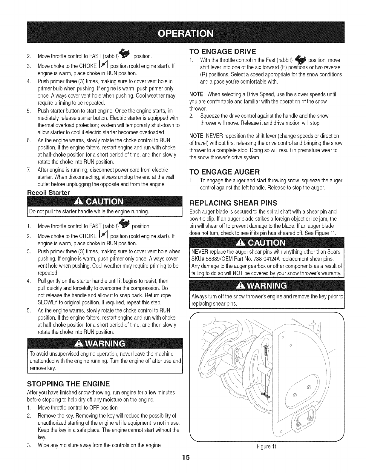
REPLACING SHEAR PINS
Eachauger blade is securedto the spiralshaftwith a shearpin and
bow-tieclip. Ifanaugerbladestrikesa foreignobjector icejam,the
pinwillshearoff to preventdamageto the blade.Ifanaugerblade
does notturn,checkto see if its pinhas shearedoff. SeeFigure11.
NEVERreplacethe auger shearpinswith anythingotherthanSears
SKU#88389/0EMPart No.738-04124Areplacementshearpins.
Anydamageto the augergearboxor othercomponentsas a resultof
[fa ngto doso w NOTbe coveredby yoursnow throwers warranty.
Alwaysturnoff the snowthrower'sengineandremovethe keypriorto
replacingshearpins.
s ¸......
iJ
Figure11
15
MAINTENANCE SCHEDULE
Beforeperforminganytypeofmaintenance/service,disengageall
controlsand stoptheengine.Waituntilallmovingpartshavecometo
acompletestop.Disconnectsparkplugwireandgrounditagainstthe
enginetopreventunintendedstarting.Alwayswearsafetyglassesduring
operationor whileperforminganyadjustmentsor repairs.
EachUseandevery5
hours
1st5 hours
Annuallyor 25 hours
Annuallyor 50 hours
Annuallyor 100 hours
BeforeStorage
1. Engineoil level
2. Looseor missinghardware
3. Unit and engine.
1. Engineoil
1. Sparkplug
2. Controllinkagesand pivots
3. Wheels
4. Gear shaftand Augershaft
1. Engineoil
1. Sparkplug
1. Fuelsystem
Followthe maintenanceschedulegiven below.This chart describes
serviceguidelinesonly.Usethe ServiceLogcolumnto keeptrackof
completedmaintenancetasks.To locate the nearest Sears Service
Centeror to scheduleservice,simplycontactSearsat
1-800-4-MY-HOME®.
1. Check
2. Tightenor replace
3. Clean
1. Change
1. Check
2. Lubewith light oil
3. Lubewith multipurposeautogrease
4. Lubewith light oil
1. Change
1. Change
1. Runengineuntilit stopsfrom lack
offuel
ENGINE MAINTENANCE
Checking Engine Oil
Beforelubricating,repairing,or inspecting,disengageall controls
Iandstopengine.Wait untilall movingpartshavecometo a complete
_stop.
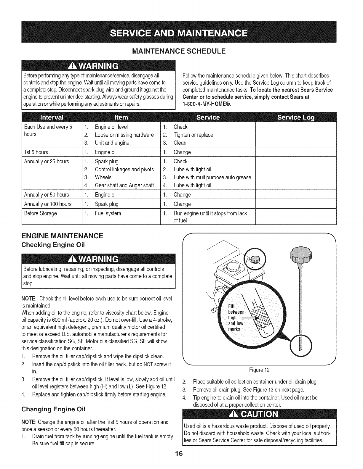
NOTE: Checktheoil levelbeforeeachuseto be surecorrectoil level
is maintained.
Whenaddingoilto the engine,referto viscositychart below.Engine
oilcapacityis 600ml (approx.20 oz.). Donot over-fill.Usea 4-stroke,
oran equivalenthighdetergent,premiumqualitymotoroilcertified
to meetorexceedU.S.automobilemanufacturer'srequirementsfor
serviceclassificationSG, SR MotoroilsclassifiedSG, SFwill show
thisdesignationonthe container.
1. Removethe oil fillercap/dipstickandwipethe dipstickclean.
2. Insertthe cap/dipstickintothe oilfiller neck,butdo NOTscrewit
in.
3. Removethe oil fillercap/dipstick.Iflevelislow,slowlyadd oil until
oil levelregistersbetweenhigh (H) and low (L). See Figure12.
4. Replaceand tighten cap/dipstickfirmlybeforestartingengine.
Changing Engine Oil
NOTE:Changethe engineoil after the first 5 hoursof operationand
oncea seasonor every 50 hoursthereafter.
1. Drainfuelfrom tank by runningengineuntilthe fuel tank isempty.
Besurefuel fill cap is secure.
Figure12
2. Placesuitableoil collectioncontainerunderoil drain plug.
3. Removeoil drain plug.SeeFigure13on nextpage.
4. Tip engineto drain oil intothe container.Usedoil mustbe
disposedof at a propercollectioncenter.
Usedoil isa hazardouswasteproduct.Disposeof usedoil properly.
IDo notdiscardwithhouseholdwaste.Checkwithyour localauthori-
lties or SearsService Centerfor safe disposal/recyclingfacilities.
16
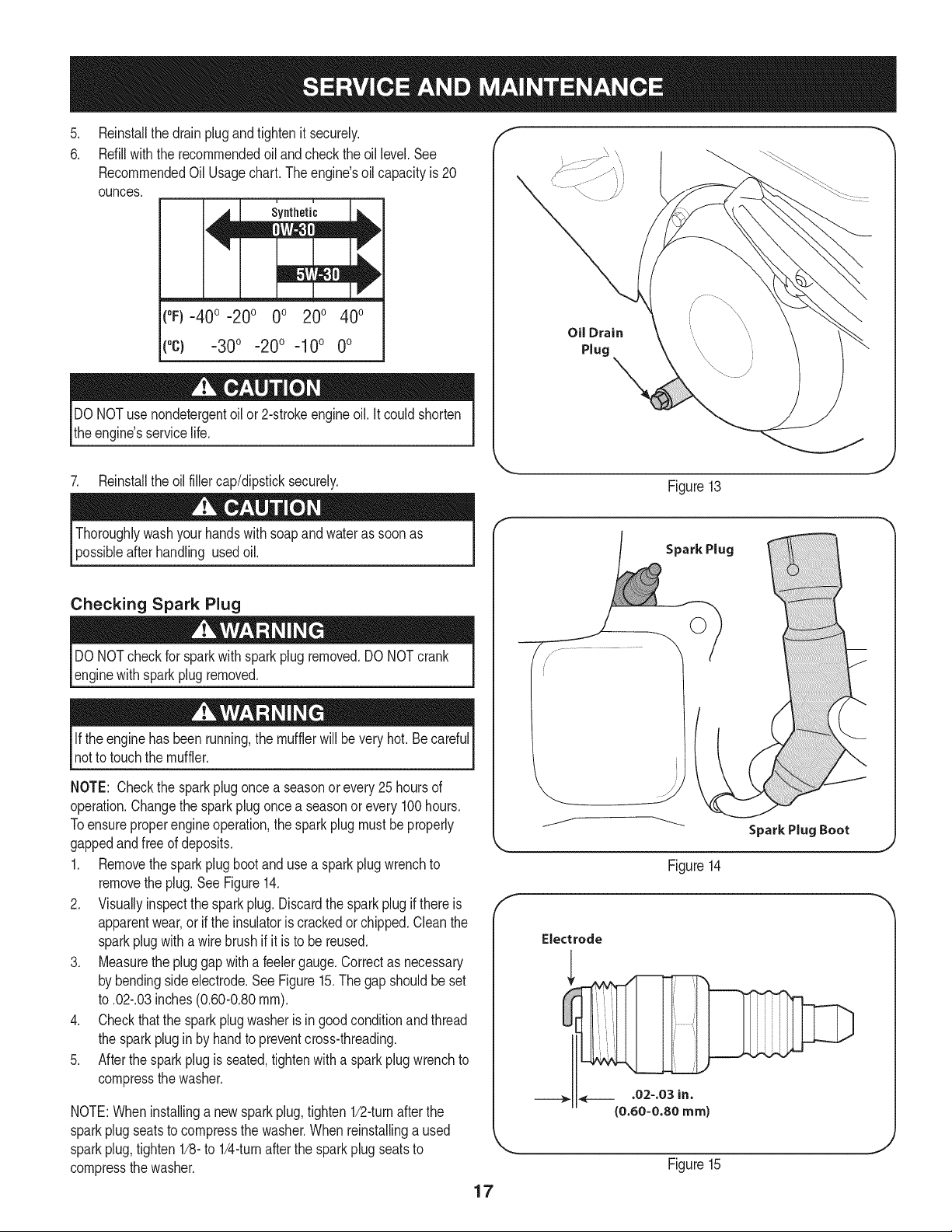
.
6.
Reinstallthe drain plugand tightenit securely.
Refillwiththe recommendedoil and checkthe oil level.See
RecommendedOil Usagechart.Theengine'soil capacityis 20
ounces.
(%-400 -200 0o 200 400
("c) -300 -200 -10° 0°
DONOTuse nondetergentoilor 2-strokeengineoil. itcould shorten
the engine'sservicelife.
7. Reinstallthe oilfillercap/dipsticksecurely.
Oil Drain
Plug
Figure13
afterhandling usedoil.
Checking Spark Plug
DO NOTcheckfor sparkwithsparkplugremoved.DO NOTcrank
enginewithsparkplugremoved.
Ifthe enginehasbeenrunning,the mufflerwill bevery hot.Becareful
notto touchthe muffler.
NOTE: Checkthe sparkplugoncea seasonor every 25 hoursof
operation.Changethe sparkplug oncea seasonor every100hours.
Toensureproperengineoperation,the sparkplugmustbe properly
gappedandfreeof deposits.
1. Removethesparkplugbootanduse a sparkplugwrenchto
removethe plug.See Figure14.
2. Visuallyinspectthe sparkplug.Discardthe spark plug if thereis
apparentwear,or if the insulatoris crackedor chipped.Cleanthe
sparkplugwitha wirebrush if it is to be reused.
3. Measurethe plug gap with a feelergauge.Correctas necessary
by bendingsideelectrode.See Figure15.The gapshouldbeset
to .02-.03inches(0.60-0.80ram).
4. Checkthatthe sparkplug washeris in good conditionandthread
the sparkplugin by handto preventcross-threading.
5. After thespark plug is seated,tightenwitha spark plugwrenchto
compressthe washer.
NOTE:Wheninstallinga newsparkplug,tighten1/2-turnafterthe
sparkplugseatsto compressthe washer.Whenreinstallinga used
sparkplug,tighten1/8-to 1/4-turnafter the sparkplug seatsto
compressthe washer.
17
Spark Plug
0
J
Figure14
Electrode
Figure15
become hotandcan inc.
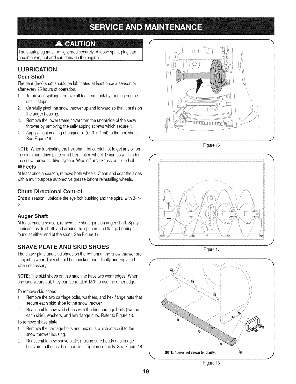
LUBRICATION
Gear Shaft
Thegear(hex)shaft shouldbe lubricatedat least oncea seasonor
afterevery25 hoursof operation.
1. Topreventspillage,removeall fuel fromtank by runningengine
until it stops.
2. Carefullypivotthe snowthrowerupandforwardso that it restson
theaugerhousing.
3. Removethe lowerframecover fromthe undersideof the snow
throwerby removingthe self-tappingscrewswhich secureit.
4. Applya lightcoatingof engineoil (or 3-in-1oil) to the hexshaft.
SeeFigure16.
NOTE:Whenlubricatingthe hexshaft, be carefulnotto get any oil on
thealuminumdriveplateor rubberfrictionwheel.Doingsowill hinder
the snowthrower'sdrive system.Wipeoff anyexcessor spilledoil.
Wheels
At leastoncea season,removebothwheels.Cleanandcoattheaxles
witha multipurposeautomotivegreasebeforereinstallingwheels.
Chute Directional Control
Oncea season,lubricatethe eye boltbushingand thespiralwith 3-in-1
oil.
Auger Shaft
At leastoncea season,removethe shearpinson augershaft. Spray
lubricantinsideshaft,andaroundthe spacersandflangebearings
foundat eitherendof the shaft.SeeFigure17.
f
Figure16
SHAVE PLATE AND SKID SHOES
The shaveplateand skid shoeson the bottomof the snowthrowerare
subjectto wear.They shouldbe checkedperiodicallyandreplaced
whennecessary.
NOTE:Theskidshoeson this machinehavetwo wearedges.When
onesidewearsout,theycan be rotated1800to usethe otheredge.
To removeskidshoes:
1. Removethe twocarriagebolts,washers,andhex flangenutsthat
secureeachskidshoeto the snowthrower.
2. Reassemblenew skid shoeswith the fourcarriagebolts(twoon
eachside),washers,andhex flangenuts.Referto Figure18.
To removeshaveplate:
1. Removethe carriageboltsand hexnutswhichattachit to the
snowthrowerhousing.
2. Reassemblenew shaveplate,makingsureheadsof carriage
boltsareto the insideof housing.Tightensecurely.See Figure18.
Figure17
NOTE:Augers not shown for clarity.
Figure18
/
/
/
/
18
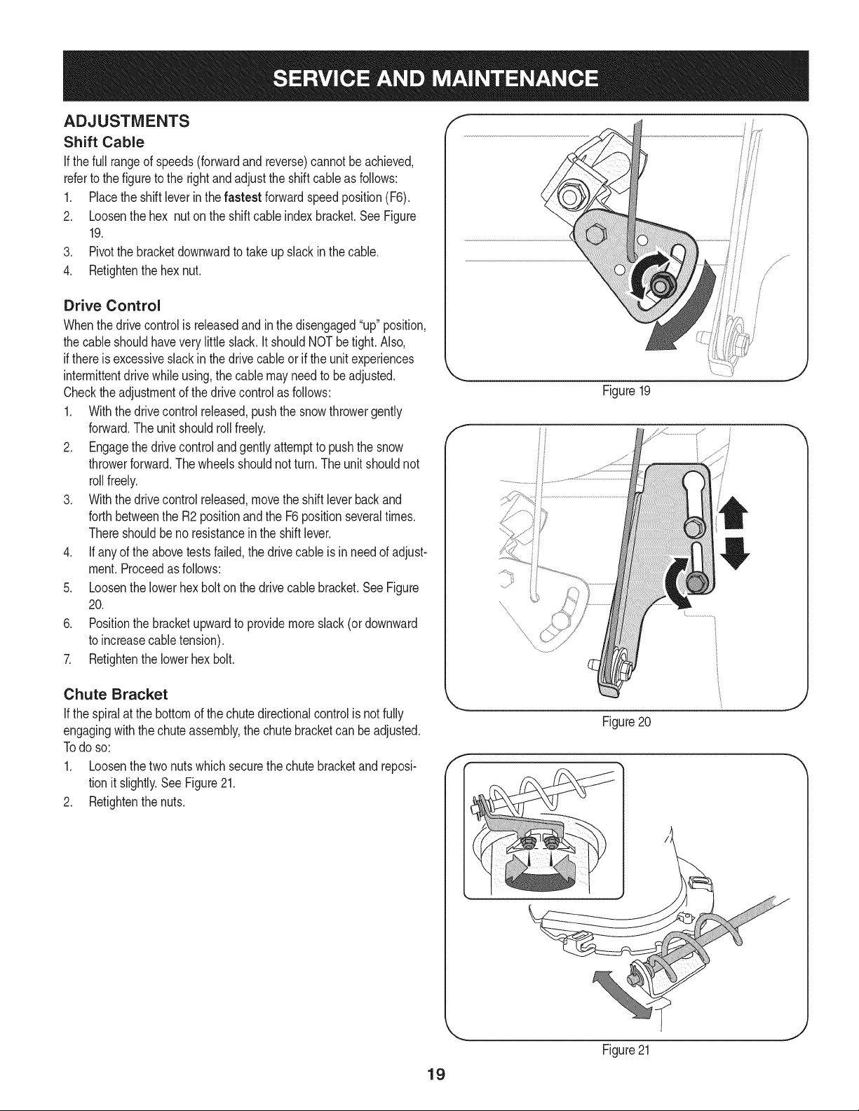
ADJUSTMENTS
Shift Cable
If thefull rangeof speeds(forwardandreverse)cannotbe achieved,
referto the figureto the rightandadjustthe shift cableas follows:
1. Placethe shiftleverin thefastest forward speedposition(F6).
2. Loosenthe hex nuton the shiftcable indexbracket.SeeFigure
19.
3. Pivotthe bracketdownwardto takeupslack inthe cable.
4. Retightenthehex nut.
Drive Control
Whenthedrivecontrolis releasedand in thedisengaged"up"position,
the cableshouldhavevery little slack.It shouldNOTbe tight. Also,
if thereis excessiveslackin thedrive cableor if the unitexperiences
intermittentdrivewhileusing,the cable mayneed to be adjusted.
Checktheadjustmentof the drivecontrolas follows:
1. Withthedrivecontrolreleased,pushthe snowthrowergently
forward.The unitshouldroll freely.
2. Engagethe drivecontroland gently attemptto pushthe snow
throwerforward.Thewheelsshouldnotturn.The unitshouldnot
rollfreely.
3. With thedrivecontrol released,movethe shift leverbackand
forthbetweenthe R2positionandthe F6 positionseveraltimes.
Thereshouldbeno resistancein the shiftlever.
4. If anyof the abovetestsfailed,the drivecable is in needof adjust-
ment.Proceedas follows:
5. Loosenthe lowerhexbolt onthe drivecable bracket.SeeFigure
20.
6. Positionthe bracketupwardto providemoreslack(or downward
to increasecabletension).
7. Retightenthe lowerhex bolt.
Chute Bracket
If the spiralat the bottomof the chutedirectionalcontrolis notfully
engagingwiththe chuteassembly,the chute bracketcan beadjusted.
Todo so:
1. Loosenthe two nuts which securethechutebracketand reposi-
tion it slightly.See Figure21.
2. Retightenthe nuts.
Figure19
f
/
Figure20
f
19
Figure21
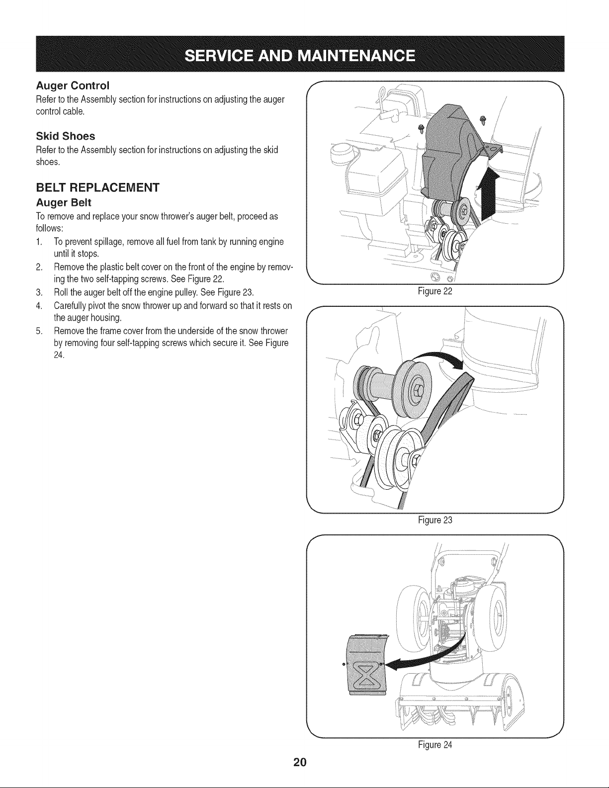
Auger Control
Referto the Assemblysectionfor instructionsonadjustingtheauger
controlcable.
Skid Shoes
Referto the Assemblysectionfor instructionsonadjustingthe skid
shoes.
BELT REPLACEMENT
Auger Belt
To removeandreplaceyoursnow thrower'saugerbelt,proceedas
follows:
1. Topreventspillage,removeall fuel fromtank by runningengine
until itstops.
2. Removethe plasticbelt coveron the front of the engineby remov-
ingthe twoself-tappingscrews.See Figure22.
3. Rollthe auger beltoff theengine pulley.See Figure23.
4. Carefullypivotthe snowthrowerupandforwardso that itrestson
theaugerhousing.
5. Removethe framecoverfromthe undersideof the snowthrower
by removingfourself-tappingscrewswhich secureit. See Figure
24.
f
Figure22
J
f
Figure 23
//
2O
Figure24
J
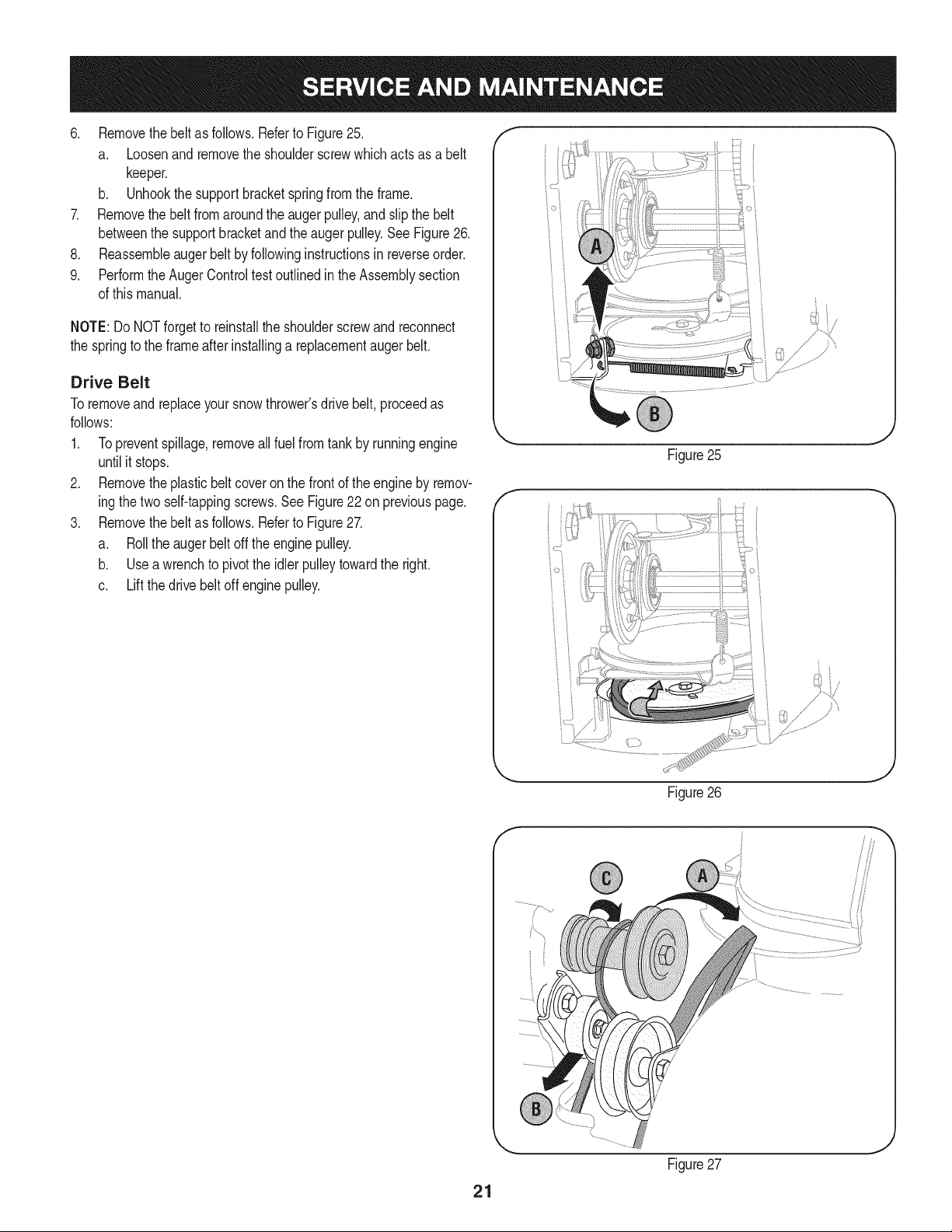
6. Removethebeltasfollows.RefertoFigure25.
a. Loosenandremovetheshoulderscrewwhichactsasabelt
keeper.
b. Unhookthesupportbracketspringfromtheframe.
7. Removethebeltfromaroundtheaugerpulley,andslipthebelt
betweenthesupportbracketandtheaugerpulley.SeeFigure26.
8. Reassembleaugerbeltbyfollowinginstructionsinreverseorder.
9. PerformtheAugerControltestoutlinedintheAssemblysection
ofthismanual.
NOTE:DoNOTforgettoreinstalltheshoulderscrewandreconnect
thespringtotheframeafterinstallingareplacementaugerbelt.
Drive Belt
Toremoveand replaceyoursnowthrower'sdrivebelt, proceedas
follows:
1. Topreventspillage,removeallfuel fromtankby runningengine
untilit stops.
2. Removetheplasticbelt coveronthe frontof the engineby remov-
ingthe twoself-tappingscrews.See Figure22 on previouspage.
3. Removethebelt as follows.Referto Figure27.
a. Rollthe auger beltoff theengine pulley.
b. Use a wrenchto pivotthe idlerpulleytowardthe right.
c. Liftthe drivebelt off enginepulley.
/" }
Figure25
Figure26
21
Figure27
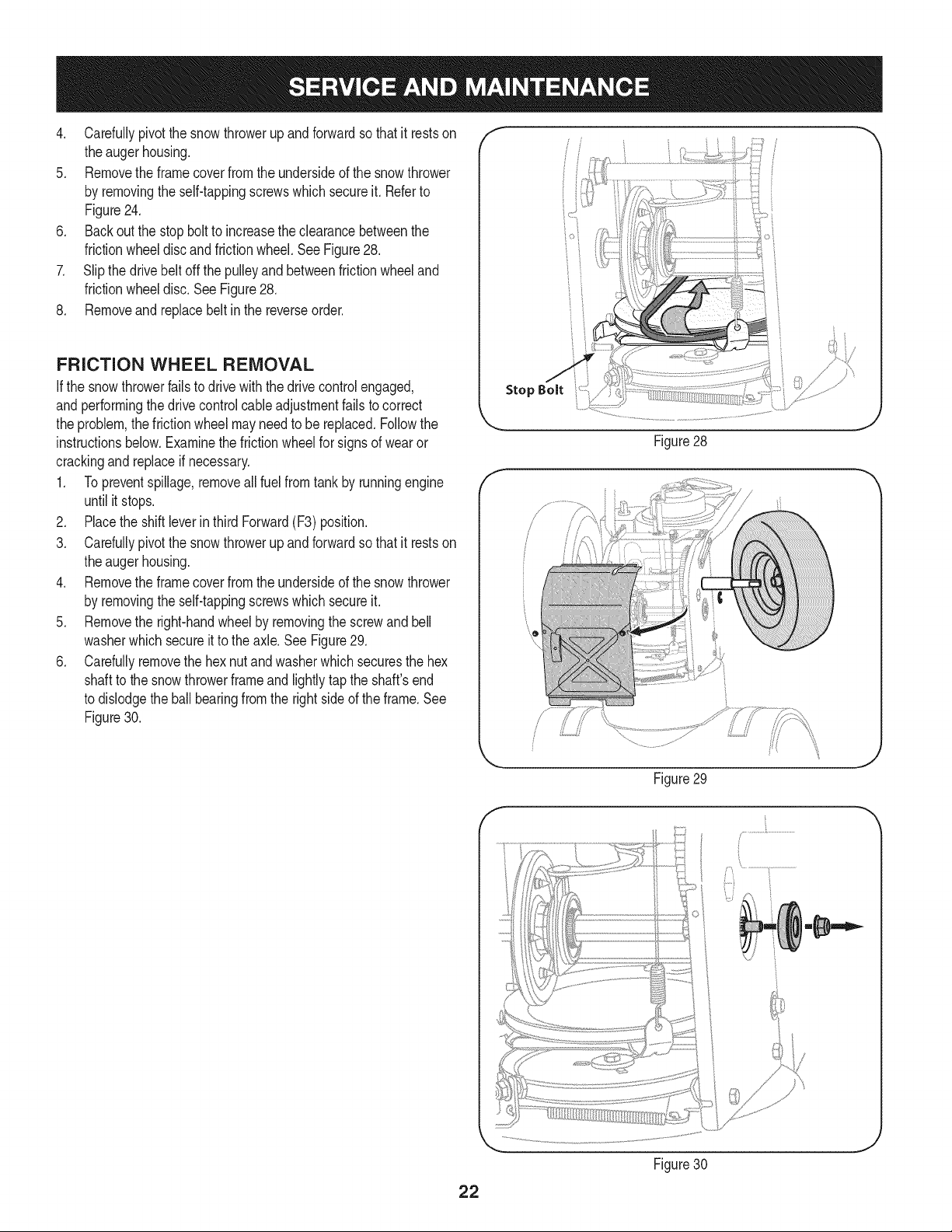
4, Carefullypivotthesnowthrowerupandforwardsothatitrestson
theaugerhousing.
5. Removetheframecoverfromtheundersideofthesnowthrower
byremovingtheself-tappingscrewswhichsecureit.Referto
Figure24,
6. Backoutthestopbolttoincreasetheclearancebetweenthe
frictionwheeldiscandfrictionwheel,SeeFigure28,
7. Slipthedrivebeltoffthepulleyandbetweenfrictionwheeland
frictionwheeldisc,SeeFigure28,
8, Removeandreplacebeltinthereverseorder,
FRiCTiON WHEEL REMOVAL
Ifthe snowthrowerfailsto drive withthedrivecontrolengaged,
andperformingthe drivecontrolcableadjustmentfailsto correct
the problem,the frictionwheelmayneedto be replaced.Followthe
instructionsbelow.Examinethe frictionwheelfor signsof wearor
crackingand replaceif necessary.
1. Topreventspillage,removeall fuel fromtank by runningengine
until it stops.
2. Placethe shiftleverin third Forward(F3) position.
3. Carefullypivotthe snowthrowerupandforwardso that it restson
theaugerhousing.
4. Removethe framecoverfromthe undersideof the snowthrower
by removingthe self-tappingscrewswhich secureit.
5. Removethe right-handwheelby removingthe screwandbell
washerwhichsecureit to theaxle.See Figure29.
6. Carefullyremovethe hexnut andwasherwhichsecuresthe hex
shaftto the snowthrowerframeand lightlytap the shaft'send
to dislodgethe ball bearingfrom the rightsideof theframe.See
Figure30.
Stop Bolt
Figure28
J
Figure29
f
Figure30
J
22
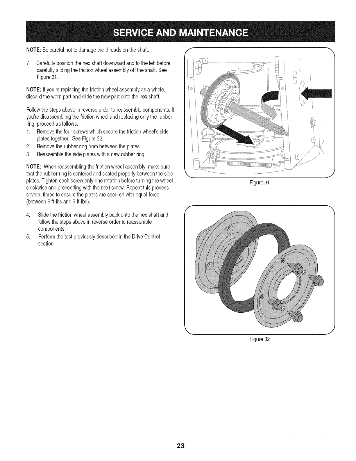
NOTE:Becarefulnot to damagethe threadson the shaft,
7. Carefullypositionthe hexshaftdownwardandto the left before
carefullyslidingthe frictionwheelassemblyoff the shaft.See
Figure31.
NOTE: Ifyou'rereplacingthe frictionwheelassemblyas a whole,
discardthe wornpartand slidethe newpart ontothe hexshaft.
Followthe stepsabovein reverseorder to reassemblecomponents.If
you'redisassemblingthe frictionwheeland replacingonly the rubber
ring,proceedas follows:
1. Removethefour screwswhich securethe frictionwheel'sside
platestogether. SeeFigure32.
2. Removethe rubberringfrombetweenthe plates.
3. Reassemblethe side plateswith a newrubberring.
NOTE: Whenreassemblingthe frictionwheelassembly,makesure
thatthe rubberringis centeredand seatedproperlybetweenthe side
plates.Tighteneachscrewonlyone rotationbeforeturningthe wheel
clockwiseand proceedingwiththe nextscrew.Repeatthisprocess
severaltimes toensurethe platesaresecuredwithequalforce
(between6 ft-lbsand 9 ft-lbs).
4. Slide the frictionwheelassemblybackonto the hexshaftand
followthestepsabovein reverseorder to reassemble
components.
5. Performthe testpreviouslydescribedin the DriveControl
section.
Figure31
... j
Figure32
23
Ifthe snowthrowerwillnot be usedfor30 daysor longer,or if it is the end of the snowseasonwhenthe last possibilityof snowis gone,the
equipmentneedsto bestoredproperly.Followstorageinstructionsbelowto ensuretop performancefrom the snowthrowerfor manymoreyears.
PREPARING ENGINE
Enginesstoredover30 daysneedto be drainedof fuel to prevent
deteriorationandgumfromforminginfuel systemor on essential
carburetorparts.If thegasolinein yourenginedeterioratesduring
storage,youmay needto havethe carburetor,and otherfuel system
components,servicedor replaced.
1. Removeall fuel fromtank by runningengineuntil it stops.
2. Changethe engineoil.
3. Removesparkplugandpourapproximately1 oz. (30 rnl) of clean
engineoil intothe cylinder.Pullthe recoilstarterseveraltimesto
distributetheoil, and reinstallthe spark plug.
4. Cleandebrisfromaroundengine,andunder,around,and behind
muffler.Applya lightfilm of oil on anyareasthatare susceptible
to rust.
• Storeina clean,dry andwellventilatedarea awayfrom anyap-
pliancethat operateswith a flameor pilotlight,suchas a furnace,
waterheater,or clothesdryer.Avoidany areawitha spark
producingelectricmotor,or wherepowertools are operated.
Neverstoresnowthrowerwithfuel intank indoorsor in poorlyventi-
latedareas,wherefuel fumesmay reachan openflame,spark or pilol
lightas ona furnace,water heater,clothesdryer orgas appliance.
• If possible,avoidstorageareaswith high humidity.
• Keepthe enginelevelin storage.Tiltingcan causefuel or oil
leakage.
PREPARING SNOW THROWER
Whenstoringthe snowthrowerin anunventilatedor metal stor-
age shed,careshouldbetakento rustprooftheequipment.Using
a light oilor silicone,coat theequipment,especiallyanychains,
springs,bearingsand cables.
• Removealldirt fromexteriorof engineandequipment.
• Followlubricationrecommendations.
• Storeequipmentin a clean,dry area.
24
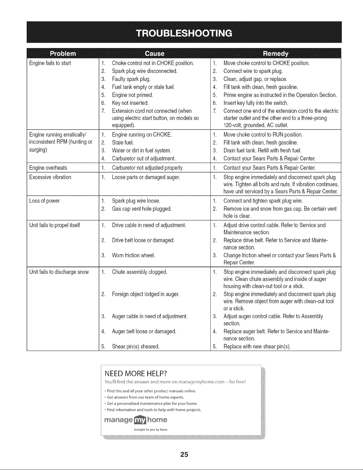
Enginefailsto start
Enginerunningerratically/
inconsistentRPM(huntingor
surging)
Engineoverheats
Excessivevibration
Lossof power
Unitfailsto propelitself
Unitfailsto dischargesnow
1. Chokecontrolnot in CHOKEposition.
2. Sparkplugwire disconnected.
3. Faultysparkplug.
4. Fueltank emptyor stale fuel.
5. Enginenotprimed.
6. Keynot inserted.
7. Extensioncordnot connected(when
usingelectricstartbutton,onmodelsso
equipped).
1. Enginerunningon CHOKE.
2. Stalefuel.
3. Wateror dirt in fuel system.
4. Carburetorout of adjustment.
1. Carburetornot adjustedproperly.
1. Loosepartsor damagedauger.
1. Sparkplugwire loose.
2. Gascap vent hole plugged.
1. Drivecable in need of adjustment.
2. Drivebelt looseor damaged.
3. Wornfrictionwheel.
1. Chuteassemblyclogged.
2. Foreignobjectlodgedinauger.
3. Augercablein needof adjustment.
4. Augerbelt looseor damaged.
5. Shearpin(s) sheared.
1. Movechokecontrolto CHOKEposition.
2. Connectwireto sparkplug.
3. Clean,adjustgap,or replace.
4. Filltank with clean, freshgasoline.
5. Primeengineas instructedinthe OperationSection.
6. Insertkeyfully intothe switch.
7. Connectoneendof the extensioncordto the electric
starteroutlet and the otherend to a three-prong
120-volt,grounded,ACoutlet.
1. Movechokecontrolto RUNposition.
2. Filltank with clean, freshgasoline.
3. Drainfueltank. Refillwith freshfuel.
4. ContactyourSearsParts& RepairCenter.
1. ContactyourSearsParts& RepairCenter.
1. Stopengineimmediatelyand disconnectsparkplug
wire.Tightenall boltsand nuts.If vibrationcontinues,
haveunitservicedbya SearsParts & RepairCenter.
1. Connectandtightensparkplugwire.
2. Removeice andsnowfromgascap.Becertainvent
holeis clear.
1. Adjustdrivecontrolcable. Referto Serviceand
Maintenancesection.
2. Replacedrive belt. Referto Serviceand Mainte-
nancesection.
3. Changefrictionwheelor contactyour SearsParts&
RepairCenter.
1. Stopengineimmediatelyand disconnectsparkplug
wire.Cleanchuteassemblyandinsideof auger
housingwith clean-outtool or a stick.
2. Stopengineimmediatelyand disconnectsparkplug
wire.Removeobjectfrom augerwith clean-outtool
ora stick.
3. Adjustaugercontrolcable. Referto Assembly
section.
4. Replaceauger belt. Referto Serviceand Mainte-
nancesection.
5. Replacewith new shearpin(s).
NEED MORE .HELP?
o Find this and all your other product manuals online.
, Get answers from our team of home experts. _}
o Get a personalized maintenance plan for your home.
Find information and tools to help with home projects.
25
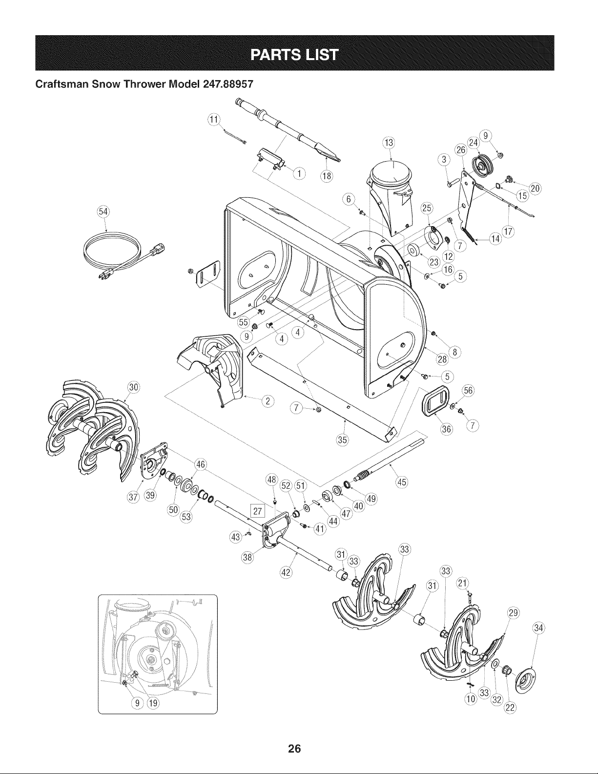
Craftsman Snow Thrower IViodel 247.88957
I
I
/
i
)i
26
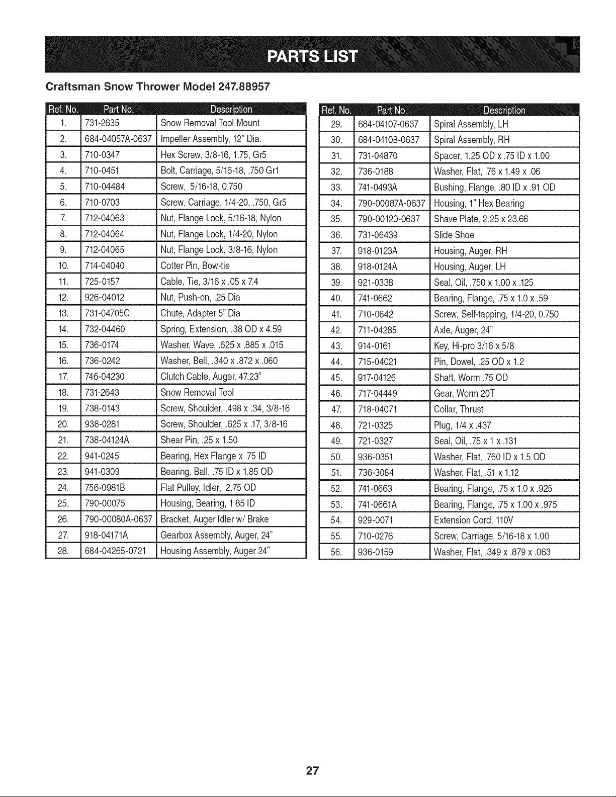
Craftsman Snow Thrower IViodel 247.88957
D = 0 0
731-2635 SnowRemovalToolMount
2. 684-04057A-0637 ImpellerAssembly,12"Dia.
3. 710-0347 HexScrew,3/8-16,1.75,Gr5
4. 710-0451 Bolt,Carriage,5/16-18,.750Grl
5. 710-04484 Screw, 5/16-18,0.750
6. 710-0703 Screw,Carriage,1/4-20,.750,Gr5
7. 712-04063 Nut,FlangeLock,5/16-18,Nylon
8. 712-04064 Nut,FlangeLock,1/4-20,Nylon
9. 712-04065 Nut,FlangeLock,3/8-16,Nylon
10. 714-04040 Cotter Pin,Bow-tie
11. 725-0157 Cable,Tie,3/16 x .05 x 7.4
12. 926-04012 Nut,Push-on,.25 Dia
13. 731-04705C Chute,Adapter5" Dia
14. 732-04460 Spring,Extension,.38 ODx 4.59
15. 736-0174 Washer,Wave,.625x .885x .015
16. 736-0242 Washer,Bell,.340x .872x .060
17. 746-04230 ClutchCable,Auger,47.23"
18. 731-2643 Snow RemovalTool
19. 738-0143 Screw,Shoulder,.498x .34,3/8-16
20. 938-0281 Screw,Shoulder,.625x .17,3/8-16
21. 738-04124A Shear Pin,.25 x 1.50
22. 941-0245 Bearing,HexFlangex .75ID
23. 941-0309 Bearing,Ball,.75IDx 1.85OD
24. 756-0981B FlatPulley,Idler, 2.75OD
25. 790-00075 Housing,Bearing,1.85ID
26. 790-00080A-0637 Bracket,AugerIdlerw/Brake
27. 918-04171A GearboxAssembly,Auger,24"
28. 684-04265-0721 HousingAssembly,Auger24"
D = O 0
684-04107-0637 SpiralAssembly,LH
30. 684-04108-0637 SpiralAssembly,RH
31. 731-04870 Spacer,1.25OD x .75 ID x 1.00
32. 736-0188 Washer,Flat, .76x 1.49x .06
33. 741-0493A Bushing,Flange,.80 IDx .91OD
34. 790-00087A-0637 Housing,1"HexBearing
35. 790-00120-0637 ShavePlate,2.25 x 23.66
36. 731-06439 SlideShoe
37. 918-0123A Housing,Auger,RH
38. 918-0124A Housing,Auger,LH
39. 921-0338 Seal,Oil, .750x 1.00x .125
40. 741-0662 Bearing,Flange,.75x 1.0x .59
41. 710-0642 Screw,Self-tapping,1/4-20,0.750
42. 711-04285 Axle,Auger,24"
43. 914-0161 Key,Hi-pro3/16x 5/8
44. 715-04021 Pin, Dowel,.25OD x 1.2
45. 917-04126 Shaft,Worm.75OD
46. 717-04449 Gear,Worm20T
47. 718-04071 Collar,Thrust
48. 721-0325 Plug,1/4 x .437
49. 721-0327 Seal,Oil, .75x 1x .131
50. 936-0351 Washer,Flat, .760ID x 1.50D
51. 736-3084 Washer,Flat, .51x 1.12
52. 741-0663 Bearing,Flange,.75x 1.0x .925
53. 741-0661A Bearing,Flange,.75x 1.00x .975
54. 929-0071 ExtensionCord,110V
55. 710-0276 Screw,Carriage,5/16-18x 1.00
56. 936-0159 Washer,Fiat, .349x .879x .063
27
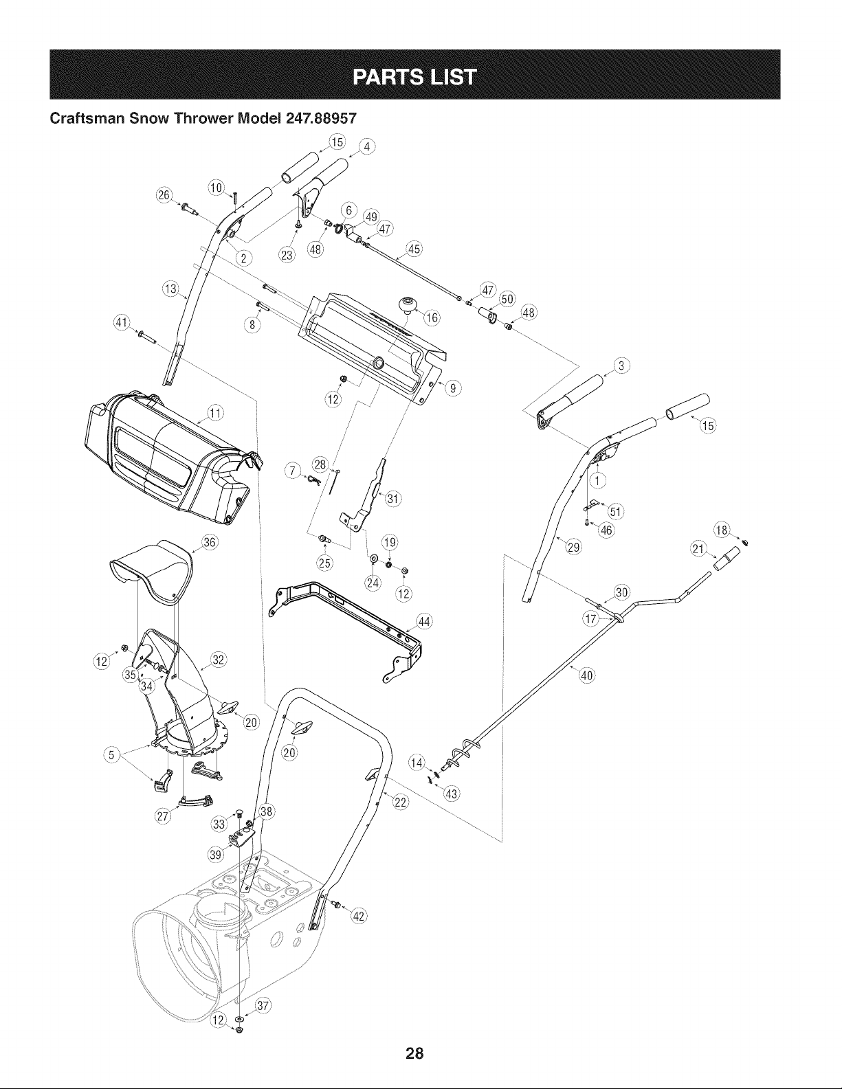
Craftsman Snow Thrower Model 247.88957
S_
,_1_i _4_
/
/
28
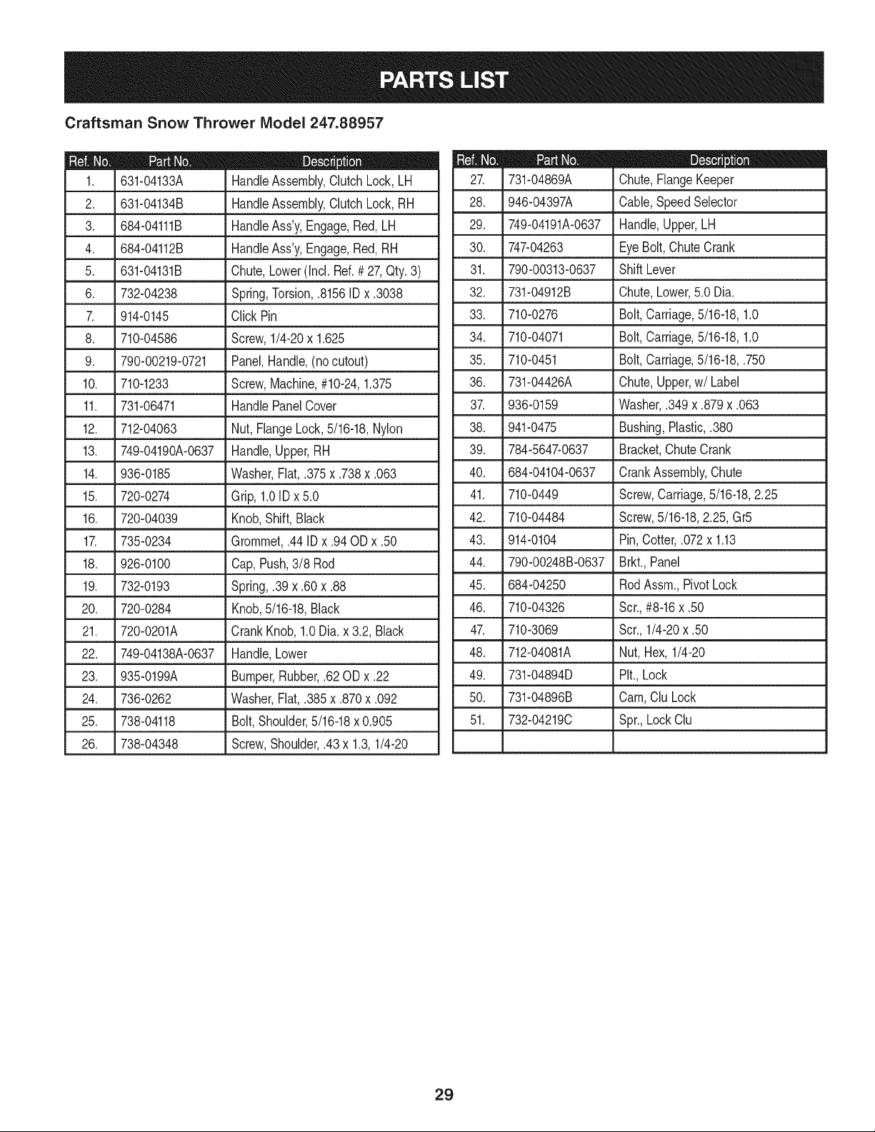
Craftsman Snow Thrower IViodel 247.88957
D = 0 !
631-04133A HandleAssembly,ClutchLock,LH
2. 631-04134B HandleAssembly,ClutchLock,RH
3. 684-04111B HandleAss'y,Engage,Red, LH
4. 684-04112B HandleAss'y,Engage,Red, RH
5: J 631-04131B _Chute.Lower(/ncl_Ref_#27,Qty. 3)
6. 732-04238 Spring,Torsion,.8156ID x .3038
7. 914-0145 ClickPin
8. 710-04586 Screw,1/4-20x 1.625
9. 790-00219-0721 Panel,Handle,(nocutout)
10. 710-1233 Screw,Machine,#10-24,1.375
11. 731-06471 HandlePanelCover
12. 712-04063 Nut,FlangeLock,5/16-18,Nylon
13. . 749-04190A-06371Hand!e,Upper,RH
14. 936-0185 Washer,Fiat,.375x .738x .063
15. 720-0274 Grip,1.0IDx 5.0
16. 720-04039 Knob,Shift, Black
17. 735-0234 Grommet,.44 IDx .94 ODx .50
18. 926-0100 Cap,Push,3/8 Rod
19. 732-0193 Spring,.39 x .60 x .88
20. 720-0284 Knob,5/16-18,Black
21. 720-0201A CrankKnob,1.0Dia.x 3.2, Black
22. 749-04138A-0637 Handle,Lower
23. 935-0199A Bumper,Rubber,.62 ODx .22
24. 736-0262 Washer,Fiat,.385x .870x .092
25. 738-04118 Bolt,Shoulder,5/16-18x 0.905
26. 738-04348 Screw,Shoulder,.43x 1.3,1/4-20
D = O O
731-04869A Chute,FlangeKeeper
28. 946-04397A Cable,SpeedSelector
29. 749-04191A-0637 Handle,Upper,LH
30. 747-04263 EyeBolt,ChuteCrank
31. 790-00313-0637 Shift Lever
32. 731-04912B Chute,Lower,5.0 Dia.
33. 710-0276 Bolt,Carriage,5/16-18,1.0
34. 710-04071 Bolt,Carriage,5/16-18,1.0
35. 710-0451 Bolt,Carriage,5/16-18,.750
36. 731-04426A Chute,Upper,w/Label
37. 936-0159 Washer,.349x .879x .063
38. 941-0475 Bushing,Plastic,.380
39. 784-5647-0637 Bracket,ChuteCrank
40. 684-04104-0637 CrankAssembly,Chute
41. 710-0449 Screw,Carriage,5/16-18,2.25
42. 710-04484 Screw,5/16-18,2.25, Gr5
43. 914-0104 Pin,Cotter,.072x 1.13
44. 790-00248B-0637 Brkt.,Panel
45. 684-04250 RodAssm.,PivotLock
46. 710-04326 Scr.,#8-16x .50
47. 710-3069 Scr.,1/4-20x .50
48. 712-04081A Nut,Hex, 1/4-20
49. 731-04894D Pit.,Lock
50. 731-04896B Cam,CluLock
51. 732-04219C Spr.,LockClu
29
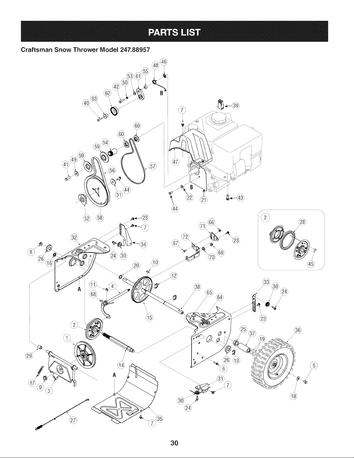
Craftsman Snow Thrower Model 247.88957
,_8h, _3L
i
//
/
/
30
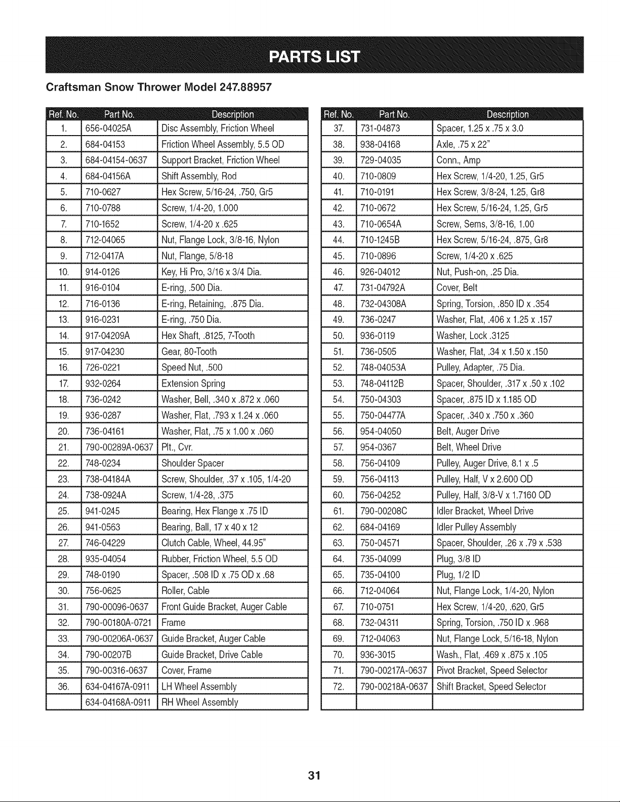
Craftsman Snow Thrower IViodel 247.88957
I = 0 0
656-04025A DiscAssembly,FrictionWheel
2. 684-04153 FrictionWheelAssembly,5.50D
3. 684-04154-0637 SupportBracket,FrictionWheel
4. 684-04156A ShiftAssembly,Rod
5. J 710-0627 J HexScrew,5/16-24,.750,Gr5
6. 710-0788 Screw,1/4-20,1.000
7. 710-1652 Screw,1/4-20x .625
8. 712-04065 Nut,FlangeLock,3/8-16,Nylon
9. 712-0417A Nut,Flange,5/8-18
10. 914-0126 Key,Hi Pro,3/16x 3/4 Dia.
11. 916-0104 E-ring,.500 Dia.
12. 716-0136 E-ring,Retaining, .875Dia.
13. 916-0231 E-ring,.750Dia.
14. 917-04209A HexShaft,.8125,7-Tooth
15. 917-04230 Gear,80-Tooth
16. .726-0221 Speed Nut,.500
17. 932-0264 ExtensionSpring
18. 736-0242 Washer,Bell,.340x .872x .060
19. 936-0287 Washer,Flat,.793x 1.24x .060
20. 736-04161 Washer,Flat,.75x 1.00x .060
21. 790-00289A-0637 Pit.,Cvr.
22. 748-0234 ShoulderSpacer
23. 738-04184A Screw,Shoulder,.37x .105,1/4-20
24. 738-0924A Screw,1/4-28,.375
L
25. 941-0245 Bearing,HexFlangex .75 ID
26. 941-0563 Bearing,Ball,17x 40x 12
27. 746-04229 ClutchCable,Wheel,44.95"
28. 935-04054 Rubber,FrictionWheel,5.50D
29. 748-0190 Spacer,.508IDx .75ODx .68
30. 756-0625 Roller,Cable
31. 790-00096-0637 FrontGuide Bracket,Auger Cable
32. 790-00180A-0721 Frame
33. 790-00206A-0637 GuideBracket,AugerCable
34. 790-00207B Guide Bracket,Drive Cable
35. 790-00316-0637 Cover,Frame
36. 634-04167A-0911 LHWheelAssembly
634-04168A-0911 RHWheelAssembly
D = O e
731-04873 Spacer,1.25x .75x 3.0
38. 938-04168 Axle,.75x 22"
39. 729-04035 Conn.,Amp
40. 710-0809 HexScrew,1/4-20,1.25,Gr5
41. 710-0191 HexScrew,3/8-24, 1.25,Gr8
42. 710-0672 HexScrew,5/16-24,1.25,Gr5
43. 710-0654A Screw,Seres,3/8-16, 1.00
44. 710-1245B HexScrew,5/16-24,.875,Gr8
45. 710-0896 Screw,1/4-20x .625
46. 926-04012 Nut, Push-on,.25 Dia.
47. 731-04792A Cover,Belt
48. 732-04308A Spring,Torsion,.850 IDx .354
49. 736-0247 Washer,Flat, .406x 1.25x .157
50. 936-0119 Washer,Lock.3125
51. 736-0505 Washer,Flat, .34x 1.50x .150
52. 748-04053A Pulley,Adapter,.75 Dia.
53. 748-04112B Spacer,Shoulder,.317x .50 x .102
54. 750-04303 Spacer,.875ID x 1.185OD
55. 750-04477A Spacer,.340x .750x .360
56. 954-04050 Belt,AugerDrive
57. 954-0367 Belt, WheelDrive
58. 756-04109 Pulley,Auger Drive,8.1x .5
59. 756-04113 Pulley,Half,V x 2.600OD
60. 756-04252 Pulley,Half,3/8-V x 1.7160OD
61. 790-00208C IdlerBracket,Wheel Drive
62. 684-04169 IdlerPulleyAssembly
63. 750-04571 Spacer,Shoulder,.26 x .79x .538
64. 735-04099 Plug,3/8 ID
65. 735-04100 Plug,1/2 ID
66. 712-04064 Nut,FlangeLock,1/4-20,Nylon
67. 710-0751 HexScrew,1/4-20,.620,Gr5
68. 732-04311 Spring,Torsion,.750ID x .968
69. 712-04063 Nut,FlangeLock,5/16-18,Nylon
70. 936-3015 Wash.,Flat, .469x .875x .105
71. 790-00217A-0637 PivotBracket,SpeedSelector
72. 790-00218A-0637 ShiftBracket,SpeedSelector
31
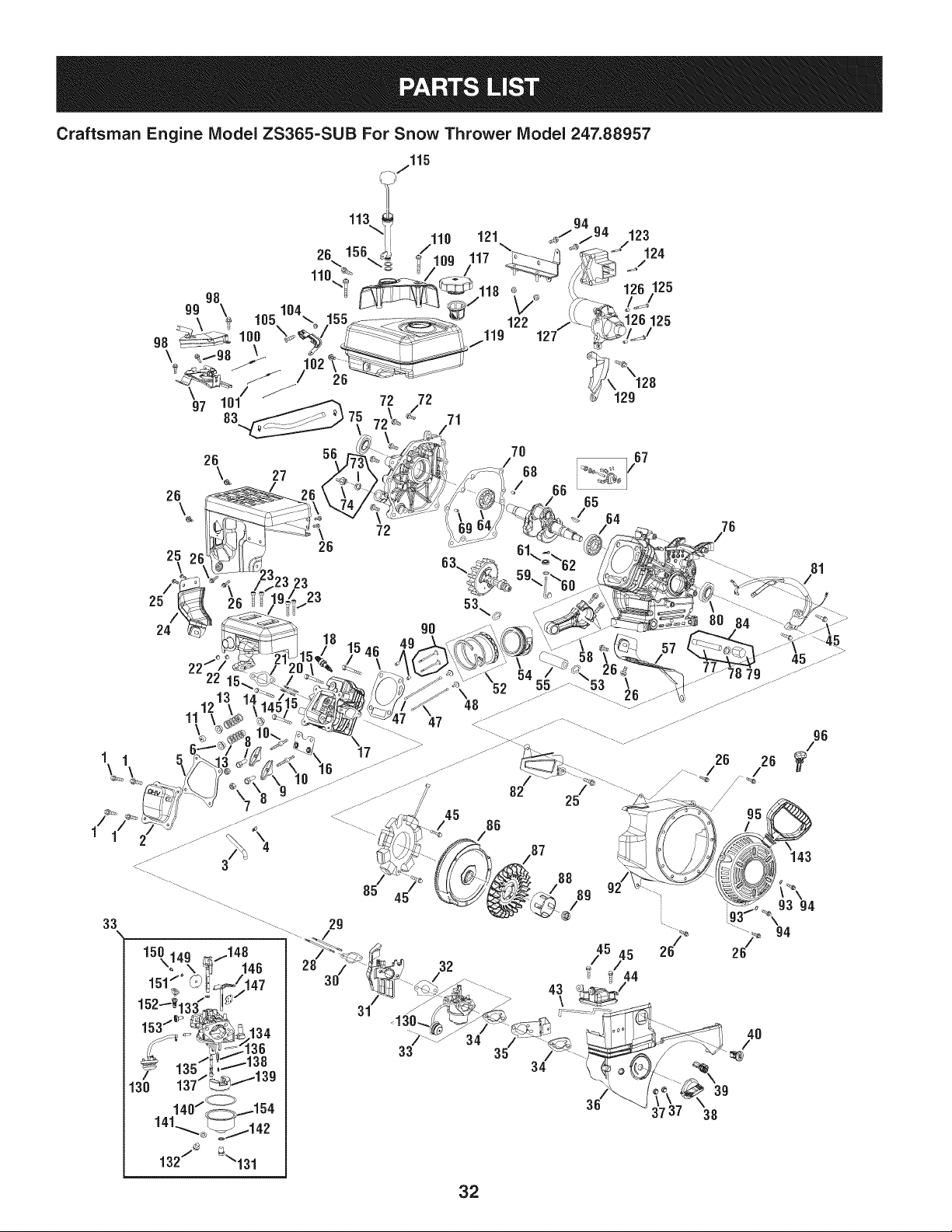
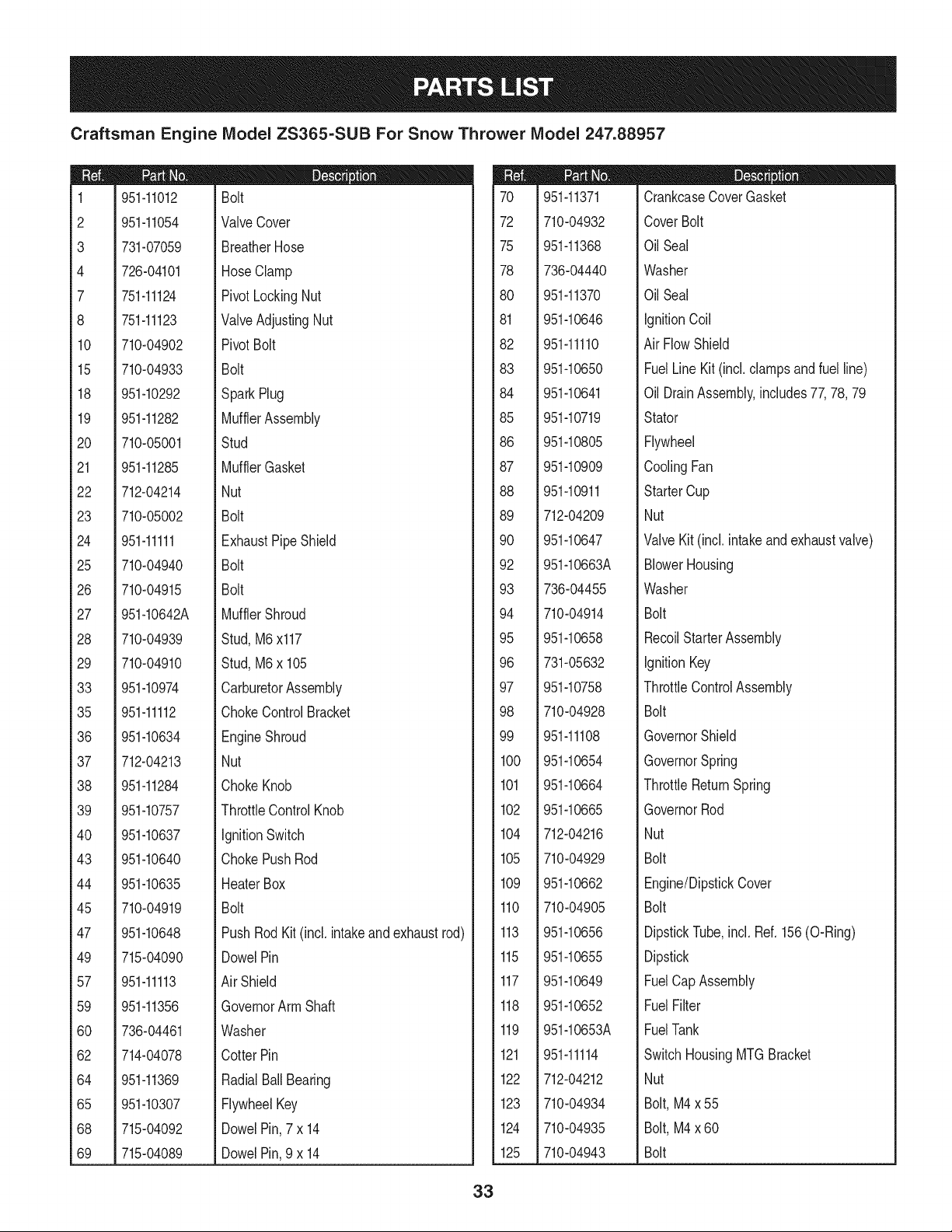
Craftsman Engine IViodel ZS365=SUB For Snow Thrower IViodel 247.88957
26 56
\_ 27
2_ 26 26 61\_\62
63_
!23 23
23
53_
24 90
/ 66
65
_/ 64
76
72 /
81
/
1/
3
33
150 149 /148
\° o\ _ 146
140/_..._154
141_b_._i_142
132/® _\131
29 \
94
26/_ 26/_
45 45
32 _/ /44
43 /
\
40
/
34
39
X
38
32
Craftsman Engine IViodel ZS365=SUB For Snow Thrower IViodel 247.88957
1
2
3
4
7
8
10
15
18
19
20
21
22
23
24
25
26
27
28
29
33
35
36
37
38
39
40
43
44
45
47
49
57
59
60
62
64
65
68
69
951-11012
951-11054
731-07059
726-04101
751-11124
751-11123
710-04902
710-04933
951-10292
951-11282
710-05001
951-11285
712-04214
710-05002
951-11111
710-04940
710-04915
951-10642A
710-04939
710-04910
951-10974
951-11112
951-10634
712-04213
951-11284
951-10757
951-10637
951-10640
951-10635
710-04919
951-10648
715-04090
951-11113
951-11356
736-04461
714-04078
951-11369
951-10307
715-04092
715-04089
Bolt
ValveCover
BreatherHose
HoseClamp
PivotLockingNut
ValveAdjustingNut
PivotBolt
Bolt
SparkPlug
MufflerAssembly
Stud
MufflerGasket
Nut
Bolt
ExhaustPipe Shield
Bolt
Bolt
MufflerShroud
Stud,M6x117
Stud,M6x 105
CarburetorAssembly
ChokeControlBracket
EngineShroud
Nut
ChokeKnob
ThrottleControlKnob
IgnitionSwitch
ChokePushRod
HeaterBox
Bolt
PushRod Kit(incl. intakeandexhaustrod)
DowelPin
Air Shield
GovernorArm Shaft
Washer
CotterPin
RadialBallBearing
FlywheelKey
DowelPin,7x 14
DowelPin,9 x 14
70
72
75
78
8O
81
82
83
84
85
86
87
88
89
90
92
93
94
95
96
97
98
99
100
101
102
104
105
109
110
113
115
117
118
119
121
122
123
124
125
951-11371
710-04932
951-11368
736-04440
951-11370
951-10646
951-11110
951-10650
951-10641
951-10719
951-10805
951-10909
951-10911
712-04209
951-10647
951-10663A
736-04455
710-04914
951-10658
731-05632
951-10758
710-04928
951-11108
951-10654
951-10664
951-10665
712-04216
710-04929
951-10662
710-04905
951-10656
951-10655
951-10649
951-10652
951-10653A
951-11114
712-04212
710-04934
710-04935
710-04943
CrankcaseCoverGasket
CoverBolt
OilSeal
Washer
OilSeal
IgnitionCoil
AirFlowShield
FuelLineKit (incl.clampsandfuel line)
OilDrainAssembly,includes77,78,79
Stator
Flywheel
CoolingFan
StarterCup
Nut
ValveKit (incl. intakeand exhaustvalve)
BlowerHousing
Washer
Bolt
RecoilStarterAssembly
IgnitionKey
ThrottleControlAssembly
Bolt
GovernorShield
GovernorSpring
ThrottleReturnSpring
GovernorRod
Nut
Bolt
Engine/DipstickCover
Bolt
DipstickTube,incl. Ref.156(O-Ring)
Dipstick
FuelCapAssembly
FuelFilter
FuelTank
SwitchHousingMTGBracket
Nut
Bolt,M4x 55
Bolt,M4x 60
Bolt
33
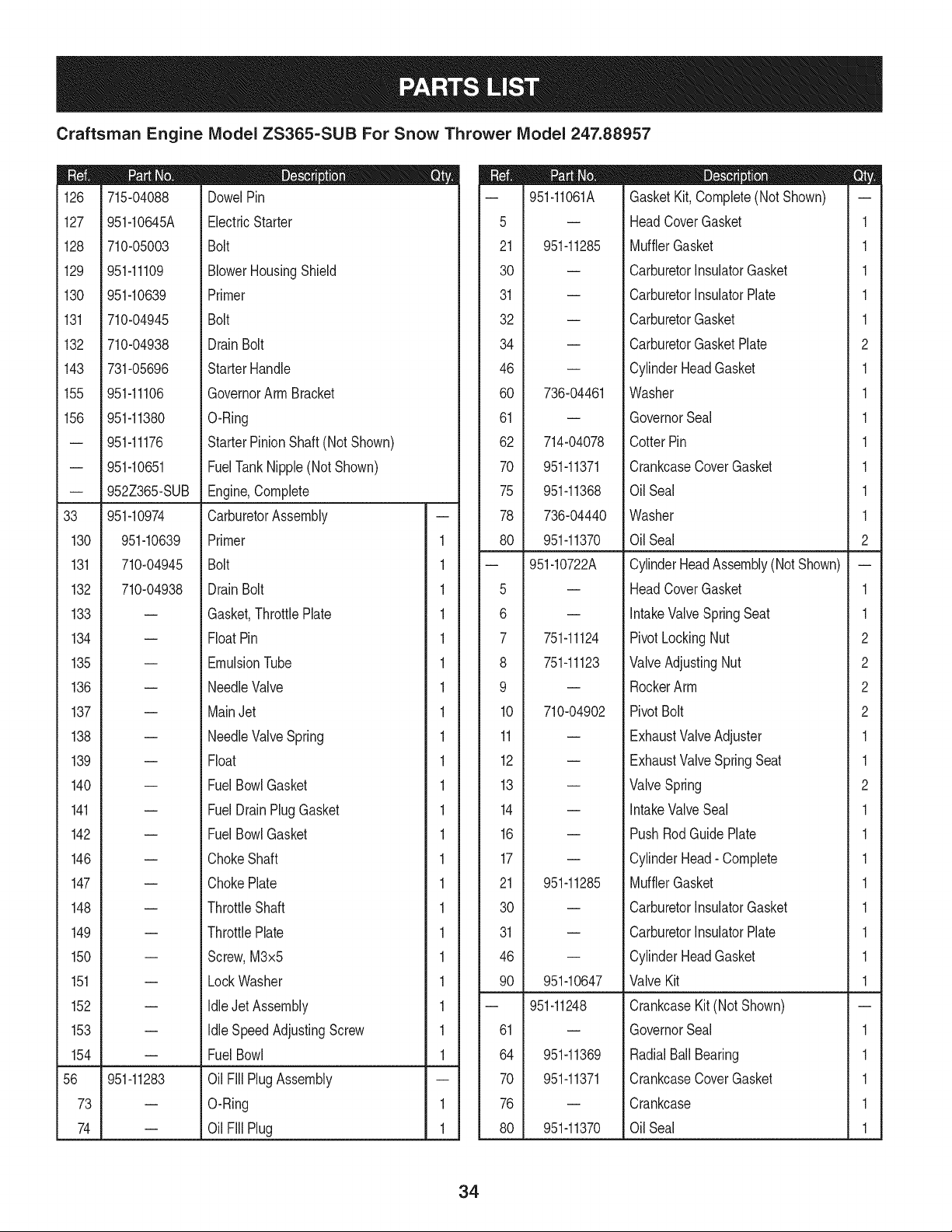
Craftsman Engine IViodel ZS365-SUB For Snow Thrower IViodel 247.88957
|= 0 o e
126 715-04088 DowelPin
127 951-10645A ElectricStarter
128 710-05003 Bolt
129 951-11109 BlowerHousingShield
130 951-10639 Primer
131 710-04945 Bolt
132 710-04938 Drain Bolt
143 731-05696 Starter Handle
155 951-11106 GovernorArm Bracket
156 951-11380 O-Ring
-- 951-11176 Starter PinionShaft(Not Shown)
-- 951-10651 FuelTankNipple(Not Shown)
-- 952Z365-SUB Engine,Complete
33 951-10974 CarburetorAssembly
130 951-10639 Primer 1
131 710-04945 Bolt 1
132 710-04938 Drain Bolt 1
133 -- Gasket,ThrottlePlate 1
134 -- FloatPin 1
135 -- EmulsionTube 1
136 -- NeedleValve 1
137 -- MainJet 1
138 -- NeedleValveSpring 1
139 -- Float 1
140 -- FuelBowlGasket 1
141 -- FuelDrain PlugGasket 1
142 -- FuelBowlGasket 1
146 -- ChokeShaft 1
147 -- ChokePlate 1
148 -- ThrottleShaft 1
149 -- ThrottlePlate 1
150 -- Screw,M3x5 1
151 -- Lock Washer 1
152 -- Idle Jet Assembly 1
153 -- Idle SpeedAdjustingScrew 1
154 -- Fuel Bowl 1
56 951-11283 Oil Fill PlugAssembly
73 -- O-Ring 1
74 -- Oil Fill Plug 1
D = O
-- 951-11061A GasketKit, Complete(NotShown) --
5 -- HeadCoverGasket 1
21 951-11285 MufflerGasket 1
30 -- CarburetorInsulatorGasket 1
31 -- CarburetorInsulatorPlate 1
32 -- CarburetorGasket 1
34 -- CarburetorGasketPlate 2
46 -- CylinderHeadGasket 1
60 736-04461 Washer 1
61 -- GovernorSeal 1
62 714-04078 CotterPin 1
70 951-11371 CrankcaseCoverGasket 1
75 951-11368 OilSeal 1
78 736-04440 Washer 1
80 951-11370 OilSeal 2
-- 951-10722A CylinderHeadAssembly(Not Shown) --
5 -- HeadCoverGasket 1
6 -- IntakeValveSpringSeat 1
7 751-11124 PivotLockingNut 2
8 751-11123 ValveAdjustingNut 2
9 -- RockerArm 2
10 710-04902 PivotBolt 2
11 -- ExhaustValveAdjuster 1
12 -- ExhaustValveSpring Seat 1
13 -- ValveSpring 2
14 -- IntakeValveSeal 1
16 -- PushRodGuidePlate 1
17 -- CylinderHead- Complete 1
21 951-11285 MufflerGasket 1
30 -- CarburetorInsulatorGasket 1
31 -- CarburetorInsulatorPlate 1
46 -- CylinderHeadGasket 1
90 951-10647 ValveKit 1
-- 951-11248 CrankcaseKit(NotShown) --
61 -- GovernorSeal 1
64 951-11369 RadialBallBearing 1
70 951-11371 CrankcaseCoverGasket 1
76 -- Crankcase 1
80 951-11370 OilSeal 1
34
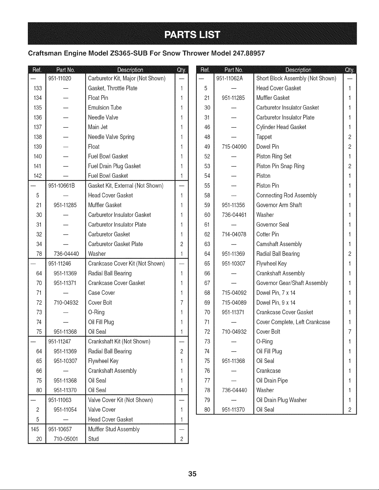
Craftsman Engine IViodel ZS365=SUB For Snow Thrower IViodel 247.88957
D = 0 0
-- 951-11020 CarburetorKit, Major(Not Shown) --
133 -- Gasket,ThrottlePlate 1
134 -- FloatPin 1
135 -- EmulsionTube 1
136 -- NeedleValve 1
137 -- MainJet 1
138 -- NeedleValveSpring 1
139 -- Float 1
140 -- Fuel BowlGasket 1
141 -- Fuel DrainPlugGasket 1
142 -- Fuel BowlGasket 1
-- 951-10661B GasketKit, External(Not Shown) --
5 -- HeadCoverGasket 1
21 951-11285 MufflerGasket 1
30 -- CarburetorInsulatorGasket 1
31 -- CarburetorInsulatorPlate 1
32 -- CarburetorGasket 1
34 -- CarburetorGasketPlate 2
78 736-04440 Washer 1
-- 951-11246 CrankcaseCoverKit (Not Shown) --
64 951-11369 RadialBall Bearing 1
70 951-11371 CrankcaseCoverGasket 1
71 -- CaseCover 1
72 710-04932 CoverBolt 7
73 -- O-Ring 1
74 -- Oil Fill Plug 1
75 951-11368 Oil Seal 1
-- 951-11247 CrankshaftKit (NotShown) --
64 951-11369 RadialBall Bearing 2
65 951-10307 FlywheelKey 1
66 -- CrankshaftAssembly 1
75 951-11368 Oil Seal 1
80 951-11370 Oil Seal 1
-- 951-11063 ValveCoverKit (Not Shown) --
2 951-11054 ValveCover 1
5 -- HeadCoverGasket 1
145 951-10657 MufflerStudAssembly
20 710-05001 Stud 2
m
5
21
30
31
46
48
49
52
53
54
55
58
59
60
61
62
63
64
65
66
67
68
69
70
71
72
73
74
75
76
77
78
79
80
951-11062A
951-11285
715-04090
951-11356
736-04461
714-04078
951-11369
951-10307
715-04092
715-04089
951-11371
710-04932
951-11368
736-04440
951-11370
D = 0 O
ShortBlockAssembly(NotShown)
HeadCoverGasket
MufflerGasket
CarburetorInsulatorGasket
CarburetorInsulatorPlate
CylinderHeadGasket
Tappet
DowelPin
PistonRingSet
PistonPinSnapRing
Piston
PistonPin
ConnectingRodAssembly
GovernorArm Shaft
Washer
GovernorSeal
CotterPin
CamshaftAssembly
RadialBallBearing
FlywheelKey
CrankshaftAssembly
GovernorGear/ShaftAssembly
DowelPin,7 x 14
DowelPin,9 x 14
CrankcaseCoverGasket
CoverComplete,LeftCrankcase
CoverBolt
O-Ring
OilFill Plug
OilSeal
Crankcase
OilDrainPipe
Washer
OilDrainPlugWasher
OilSeal
m
1
1
1
1
1
2
2
1
2
1
1
1
1
1
1
1
1
2
1
1
1
1
1
1
1
7
1
1
1
1
1
1
1
2
35
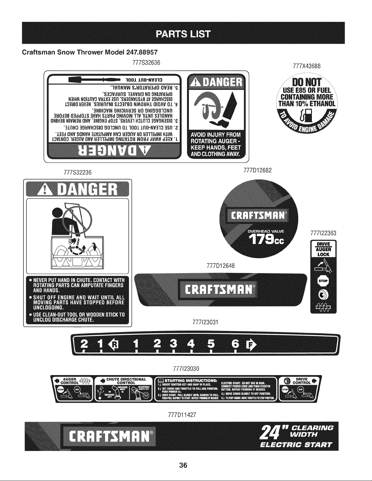
Craftsman Snow Thrower Model 247.88957
777S32636
777X43688
.....DOHOT...........
USEE85 ORFUEL
COHTAiHJHGMORE
THAH 10% ETHAHOL
J
777S32236 777D12682
777122363
777D12648
777123031
777123030
777Dl1427
36
MTD CONSUMER GROUP INC (MTD), the California Air Resources Board (CARB)
and the United States Environment Protection Agency (U. S. EPA)
Emission Control System Warranty Statement
(Owner's Defect Warranty Rights and Obligations)
EMISSIONCONTROLSYSTEMCOVERAGEIS APPLICABLETOCERTIFIEDENGINESPURCHASEDINCALIFORNIAIN 2005 ANDTHERE-
AFTER,WHICHARE USEDIN CALIFORNIA,ANDTO CERTIFIEDMODELYEAR2005ANDLATERENGINESWHICHARE PURCHASEDAND
USEDELSEWHEREIN THE UNITEDSTATES.
Californiaandelsewherein the UnitedStatesEmissionControlDefectsWarrantyCoverage
The CaliforniaAir ResourcesBoard(CARB),U.S. EPAandMTDarepleasedto explaintheemissionscontrol systemwarrantyon your modelyear
2006andlatersmalloff-roadengine.In California,new smalloff-roadenginesmustbe designed,builtand equippedto meet theStatesanti-smog
standards.Elsewhereinthe UnitedStates,newnon-road,spark-ignitionenginescertifiedfor model2005and later,mustmeetsimilarstandardsset
forthby the U.S. EPA.MTDmustwarrantythe emissioncontrolsystemonyourenginefor the periodof timelistedbelow,providedtherehasbeen
noabuse,neglector impropermaintenanceof your smalloff-roadengine.
Youremissioncontrolsystemmayincludepartssuchas the carburetor,fuel-injectionsystem,the ignitionsystem,andcatalyticconverter,fueltanks,
fuel lines,fuel caps,valves,canisters,filters,vaporhoses,clamps,connectors,andotherassociatedemission-relatedcomponents.
Wherea warrantableconditionexists,MTDwill repairyoursmall off-roadengineat no cost to yourincludingdiagnosis,partsand labor.
MANUFACTURER'S WARRANTY COVERAGE:
Thisemissionscontrolsystemis warrantedfor two years.If anyemission-relatedpart on yourengine is defective,the part will be repairedor
replacedby MTD.
OWNER'S WARRANTY RESPONSIBILITIES:
As the smalloff-roadengineowner,youare responsibleforthe performanceof the requiredmaintenancelistedinyour Owner'sManual.MTD
recommendsthatyou retainall yourreceiptscoveringmaintenanceson yoursmalloff-roadengine,but MTDcan not denywarrantysolelyfor the
lackof receiptsor foryour failureto ensurethe performanceto allscheduledmaintenance.
As the smalloff-roadengineowner,youshouldhoweverbeawarethat MTDmaydenyyour warrantycoverageif yoursmalloff-roadengineorpart
hasfaileddue toabuse, neglect,impropermaintenanceor unapprovedmodifications.
Youare responsiblefor presentingyour smalloff-roadengineto an AuthorizedMTDServiceDealeras soonas a problemexists.Thewarranted
repairsshouldbe completedina reasonableamountof time,notto exceed30 days.
Ifyou haveanyquestionsregardingyourwarrantyrightsand responsibilities,you shouldcontacta MTDServiceRepresentativeat 1-800-800-7310
andaddressis MTDCONSUMERGROUP,RO.Box361131,ClevelandOH,44136-0019.
DEFECTS WARRANTY REQUIREMENTS FOR 1995 AND LATER SMALL OFF-ROAD ENGINES:
Thissectionappliesto 1995andlater smalloff-roadengines.The warrantyperiodbeginsonthe datethe engineor equipmentis deliveredto an
ultimatepurchaser.
(a) GeneralEmissionsWarrantyCoverage
MTDmustwarrantto the ultimatepurchaserand eachsubsequentpurchaserthatthe engineis:
(1)Designed,built,and equippedsoas to conformwithallapplicableregulationsadoptedby the AirResourcesBoardpursuantto itsauthorityin
Chapters1 and 2,Part 5, Division26of the HealthandSafetyCode;and
(2) Freefrom defectsin materialsandworkmanshipthatcausethe failureof a warrantedpart to be identicalin all materialrespectsto the partas
describedin theenginemanufacturer'sapplicationfor certificationfora periodof two years.
(b)The warrantyon emissions-relatedpartswill be interpretedas follows:
(1)Anywarrantedpart thatis not scheduledfor replacementas requiredmaintenanceinthe writteninstructionsrequiredby Subsection(c)
mustbewarrantedfor the warrantyperioddefinedin Subsection(a)(2). Ifany suchpartfailsduringthe periodof warrantycoverage,it mustbe
repairedor replacedby MTDaccordingto Subsection(4)below.Anysuchpart repairedor replacedunderthewarrantymustbewarrantedfor
the remainingwarrantyperiod.
(2)Any warrantedpartthat is scheduledonlyfor regularinspectionin the writteninstructionsrequiredby Subsection(c) must bewarrantedfor
thewarrantyperioddefinedin Subsection(a)(2).A statementinsuchwritteninstructionsto the effectof "repairor replaceas necessary"will
not reducethe periodof warrantycoverage.Anysuch part repairedor replacedunderwarrantymustbe warrantedforthe remainingwarranty
period.
(3) Anywarrantedpartthat whichis scheduledfor replacementas requiredmaintenancein the writteninstructionsrequiredby Subsection(c)
mustbewarrantedfor the periodof timepriorto the first scheduledreplacementpointforthat part. If the part fails priorto thefirst scheduled
replacement,the part mustbe repairedor replacedby MTDaccordingto Subsection(4) below.Any suchpart repairedor replacedunder
warrantymustbe warrantedfor the remainderof the periodpriorto the first scheduledreplacementpointfor the part.
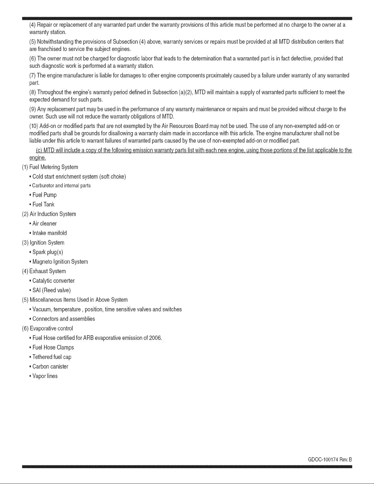
(4)Repairorreplacementofanywarrantedpartunderthewarrantyprovisionsofthisarticlemustbeperformedatnochargetotheownerata
warrantystation.
(5)NotwithstandingtheprovisionsofSubsection(4)above,warrantyservicesorrepairsmustbeprovidedatallMTDdistributioncentersthat
arefranchisedtoservicethesubjectengines.
(6)Theownermustnotbechargedfordiagnosticlaborthatleadstothedeterminationthatawarrantedpartisinfactdefective,providedthat
suchdiagnosticworkisperformedatawarrantystation.
(7)Theenginemanufacturerisliablefordamagestootherenginecomponentsproximatelycausedbyafailureunderwarrantyofanywarranted
part.
(8)Throughouttheengine'swarrantyperioddefinedinSubsection(a)(2),MTDwillmaintaina supplyofwarrantedpartssufficienttomeetthe
expecteddemandforsuchparts.
(9)Anyreplacementpartmaybeusedintheperformanceofanywarrantymaintenanceorrepairsandmustbeprovidedwithoutchargetothe
owner.SuchusewillnotreducethewarrantyobligationsofMTD.
(10)Add-onormodifiedpartsthatarenotexemptedbytheAirResourcesBoardmaynotbeused.Theuseofanynon-exemptedadd-onor
modifiedpartsshallbegroundsfordisallowingawarrantyclaimmadeinaccordancewiththisarticle.Theenginemanufacturershallnotbe
liableunderthisarticletowarrantfailuresofwarrantedpartscausedbytheuseofnon-exemptedadd-onormodifiedpart.
(c) MTDwill includea copy of the followingemissionwarrantypartslistwitheach newengine,usingthose portionsof the list applicableto the
e__&gine.
(1)FuelMeteringSystem
• Coldstart enrichmentsystem(soft choke)
,,Carburetorandinternalparts
• Fuel Pump
• FuelTank
(2)Air InductionSystem
• Air cleaner
• Intakemanifold
(3) IgnitionSystem
• Sparkplug(s)
• MagnetoIgnitionSystem
(4)ExhaustSystem
Catalyticconverter
• SAI (Reedvalve)
(5) MiscellaneousItemsUsedin AboveSystem
Vacuum,temperature, position,timesensitivevalvesand switches
Connectorsandassemblies
(6) Evaporativecontrol
• Fuel Hosecertifiedfor ARBevaporativeemissionof 2006.
• Fuel HoseClamps
Tetheredfuel cap
Carboncanister
Vaporlines
GD0C-100174Rev.B
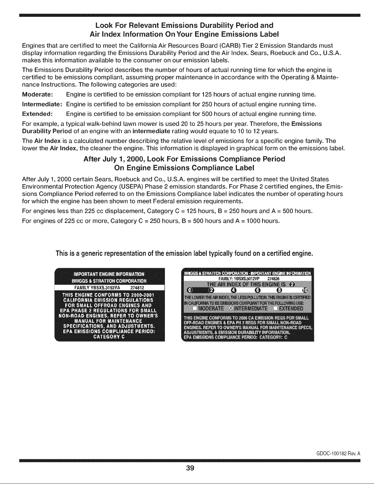
Look For Relevant Emissions Durability Period and
Air index information On Your Engine Emissions Label
Engines that are certified to meet the California Air Resources Board (CARB) Tier 2 Emission Standards must
display information regarding the Emissions Durability Period and the Air Index. Sears, Roebuck and Co., U.S.A.
makes this information available to the consumer on our emission labels.
The Emissions Durability Period describes the number of hours of actual running time for which the engine is
certified to be emissions compliant, assuming proper maintenance in accordance with the Operating & Mainte-
nance Instructions. The following categories are used:
Moderate: Engine is certified to be emission compliant for 125 hours of actual engine running time.
Intermediate: Engine is certified to be emission compliant for 250 hours of actual engine running time.
Extended: Engine is certified to be emission compliant for 500 hours of actual engine running time.
For example, a typical walk-behind lawn mower is used 20 to 25 hours per year. Therefore, the Emissions
Durability Period of an engine with an intermediate rating would equate to 10 to 12 years.
The Air Index is a calculated number describing the relative level of emissions for a specific engine family. The
lower the Air Index, the cleaner the engine. This information is displayed in graphical form on the emissions label.
After July 1,2000, Look For Emissions Compliance Period
On Engine Emissions Compliance Label
After July 1, 2000 certain Sears, Roebuck and Co., U.S.A. engines will be certified to meet the United States
Environmental Protection Agency (USEPA) Phase 2 emission standards. For Phase 2 certified engines, the Emis-
sions Compliance Period referred to on the Emissions Compliance label indicates the number of operating hours
for which the engine has been shown to meet Federal emission requirements.
For engines less than 225 cc displacement, Category C = 125 hours, B = 250 hours and A = 500 hours.
For engines of 225 cc or more, Category C = 250 hours, B = 500 hours and A = 1000 hours.
This is a generic representation of the emission label typically found on a certified engine.
FAMILYYSSXS.3192VA 274812
GDOC-100182Rev.A
39
Congratulationsonmakingasmartpurchase.YournewCraftsman®
productisdesignedandmanufacturedforyearsofdependableopera-
tion.Butlikeallproducts,itmayrequirerepairfromtimetotime.That's
whenhavingaRepairProtectionAgreementcansaveyoumoneyand
aggravation.
Here'swhattheRepairProtectionAgreement*includes:
* Expertservicebyour10,000professionalrepairspecialists
* Unlimitedserviceandnochargeforpartsandlaboronall
coveredrepairs
* Productreplacementupto$1500ifyourcoveredproductcan't be
fixed
* Discountof 10%from regularpriceof serviceand relatedinstalled
partsnotcoveredby theagreement;also, 10%off regularpriceof
preventivemaintenancecheck
* Fast help by phone- we call itRapidResolution- phonesupport
froma Searsrepresentative.Thinkof usas a "talkingowner's
manual."
Once youpurchasethe Agreement,a simplephonecall isall that it
takesfor youto scheduleservice.Youcan call anytimedayor night, or
schedulea serviceappointmentonline.
The RepairProtectionAgreementisa risk-freepurchase.Ifyou cancel
for any reasonduringthe productwarrantyperiod,wewill providea full
refund.Or,a proratedrefundanytimeafterthe productwarrantyperiod
expires.Purchaseyour RepairProtectionAgreementtoday!
Some limitations and exclusionsapply. For prices and additional
informationin the U.S.A. call 1-800-827-8855.
*Coverage inCanadavaries on some items.For full details call
Sears Canada at 1-800-381-8665.
Sears Installation Service
ForSearsprofessionalinstallationof homeappliances,garagedoor
openers,waterheaters,andothermajorhomeitems,in the U.S.A.or
Canadacall 1-800-4-MY-HOME®.
40
Declaraci6n de garantia ............................ Pagina 41
Practicas operaci6n seguras ..................... Pagina 42
Montaje ...................................................... Pagina 46
Operaci6n .................................................. Pagina 50
Servicio y Mantenimiento .......................... Pagina 54
Almacenamiento fuera de temporada ....... Pagina 62
Soluci6n de problemas .............................. Pagina 63
Acuerdo de protecci6n para reparaciones .... Pagina 68
Etiquetas de seguridad .............................. Pagina 7
Lista de piezas ........................................... Pagina 26
NOmero de servicio ................................... Cubierta
posterior
GARANTiA LIMITADA CRAFTSMAN
Dos Ahos en Lanzador de Nieve
Cuandohechofuncionary rnantenidosegQntodaslasinstruccionessurninistradas,si estelanzadorde nievefalla debidoa un defectoen mate-
rialo habilidaddentrode dosa_osde la fechade cornpra,regresara cualquiertiendaSears,SearspartesdelCentrode Servicioy Reparaci6n,
Artesanoo de otto tipo desalidaen los EstadosUnidosparala reparaci6ngratuita(si la reparaci6no lasustituci6nresulteirnposible).
Estagaranfias61otendr_validezdurante90 dias si esteproductose utilizaen cualquierrnornentoparafinescornercialeso de alquiler.
Esta garantiacubreSOLOdefectos en material y habilidad.Sears no pagar_para:
• Losarficulosprescindiblesque se hacenIlevadospuestosduranteel uso normal,incluso,perono lirnitadosparabarrenahojas,patinar
zapatos,platode afeitado,esquilanalfileres,buj[a,filtro de aire,cinturones,y filtro del aceite.
• Revisi6nde rnantenirnientoest_ndar,carnbiosdeaceite,o puestasa punto.
• Reernplazodeneurn_ticoo reparaci6ncausadapor pinchazosdesdefuerade objetos,cornou_as,espinas,tocones,o cristal.
• Neurn_ticoo reernplazode ruedao reparaci6nqueresultade ropanormal,accidente,u operaci6nirnpropiao rnantenirniento.
• Las reparacionesnecesariasdebidoal abusode operador,inclusoperono lirnitadoparada_arcausadoafectandoobjetosque doblanel
marcoo el cigOe_al,o el sobreexcesode velocidaddel motor.
• Reparacionesnecesariasdebidoa negligenciadel operador,incluyendoentre otros,da_osrnec_nicoy el_ctricoocasionadoporun
alrnacenarnientonoapropiado,falla por el usode aceitede grado y/o cantidadnoapropiadao fallapor nodarrnantenirnientoal equipode
acuerdocon las instruccionescontenidasen el manualdeloperador.
• Lirnpiezao reparacionesal motor(sisternadecombustible)provocadaspor un combustiblecontarninadou oxidado(viejo).En general,el
combustibledebeutilizarseen un perbdo no mayorde 30d[asa partirde su adquisici6n.
• Elernpejorarnientonormaly la ropade losfinesexteriores,o productoetiquetanel reernplazo.
Estagaranfias61otendrAvalidezrnientrasel productose utiliceen los EstadosUnidos.
Estagaranfialeotorgaderechoslegalesespedficos,peroustedpodr[agozarde otrosderechosen raz6nde su lugarde residencia.
Sears, Roebuck and Co., HoffmanEstates, IL 60179
Tipode aceitedel motor:
Capacidaddeaceitedel motor:
Capacidaddecombustible:
Bujfas:
Separaci6nde lasbujias:
5W-30
20 onzas
2.3 cuartos
Torch F6RTC (F6TC)
.020" a .030"
N_merode modelo ..........................................................
N_merode serie ..............................................................
Fechade compra .............................................................
Registrearriba el nOrnerodel rnodelo,elnOrnerode seriey lafecha
decornpra
© Sears Brands,LLC
41
Lapresenciade este sirnboloindicaque setrata de instrucciones
irnportantesde seguridadquese debenrespetarparaevitar
ponerenpeligrosu seguridadpersonaly/o materialy la de otras
personas.Lea y sigatodas lasinstruccionesdeestemanualantes
de poneren funcionarnientoestarn_.quina.Si no respetaestas
instruccionespodria provocarlesionespersonales.Cuandoveaeste
sirnbolo,ipresteatenci6na la advertencia!
PROPOSICI6N 65 DE CALIFORNIA
Elescapedel motorde este producto,algunosdesuscornponentes
y algunoscornponentesdelvehiculocontieneno liberansustancias
quirnicasqueelestadode Californiaconsideraque puedenproducir
c_.ncer,defectosde nacirnientou otros problernasreproductivos.
Estarn_.quinarueconstruidaparaseroperadadeacuerdocon
las reglasde seguridadcontenidasen este manual.AI igualque
concualquiertipo de equipo rnotorizado,undescuidoo error por
partedeloperadorpuedeproducirlesionesgraves.Estarn_.quina
es capazde arnputarrnanosy piesy dearrojarobjetoscon gran
fuerza.De norespetarlas instruccionesde seguridadsiguientesse
puedenproducirlesionesgraveso la rnuerte.
Su responsabilidad--Restrinja el usode estarn_.quina
rnotorizadaalas personasque lean,cornprendany respetenlas
advertenciase instruccionesqueaparecenenestemanualyen la
rn_.quina.
iGUARDEESTASINSTRUCCIONES!
CAPACITACION
• Lea,entienday curnplatodaslas instruccionesincluidasen
la rn_.quinayen los rnanualesantesde rnontarlay utilizarla.
Guardeestemanualen un lugarseguroparaconsultasfuturasy
peri6dicas,asi cornopara solicitarrepuestos.
• Leael Manualdel Operadory sigatodas las advertenciase
instruccionesde seguridad.El fracasode hacerasi puedecausar
la heridaseriaal operadory/o personaspresentes.Para Ilarnada
de preguntas,1-800-4MY-HOME.
• Farniliaricesecontodos los controlesy con el usoadecuado
de losrnisrnos.Sepa c6rnodetenerlarn_.quinay desactivarlos
controlesr_.pidarnente.
• No perrnitanuncaque losni_os rnenoresde 14a_osutilicen
estarn_.quina.Los ni_osde 14a_osenadelantedebenleery
entenderlas instruccionesde operaci6ny norrnasde seguridad
contenidasen este manual,yen la rn_.quinaydebenserentrena-
dosy supervisadospor un adulto.
• Nuncaperrnitaque los adultosoperenesta rn_.quinasin recibir
antesla instrucci6napropiada.
• Losobjetosarrojadospor la rn_.quinapuedenproducirlesiones
graves.Planifiqueel patr6nen el que va air arrojandonievepara
evitarquela descargade materialse realicehacialos carninos,
los observadores,etc.
• Mantengaa los observadores,ayudantes,rnascotasy ni_ospor
Io rnenosa 75 piesde la rn_.quinarnientrasla rnisrnaest,.en
funcionarniento.Detengala rn_.quinasialguiense acerca.
• Seaprecavidoparaevitarpatinarseo caerseespecialrnente
cuandoopera la rn_.quinaen reversa.
PREPARATIVOS
Inspeccionerninuciosarnenteel _.readondeutilizar_,el equipo.Saque
todoslos felpudos,peri6dicos,trineos,tablas,cablesy otrosobjetos
extra_oscon los que podriatropezaro que podrianser arrojadospor
la barrena/ irnpulsor.
• Paraprotegerselosojos utilice siernpreanteojoso antiparras
de seguridadrnientrasopera la rn_.quinao rnientrasla ajusta
o repara.Losobjetosarrojadosquerebotanpuedenproducir
lesionesocularesgraves.
• Noopere la rn_.quinasin la vestirnentaadecuadaparaestar al
aire libreen invierno.No utilicealhajas,bufandaslargasu otras
prendassueltasque podrianenredarseen las partesrn6viles.
Utiliceun calzadoespecialpara superficiesresbaladizas.
• Useun prolongadory un tornacorrientedetrescablescon
conexi6natierra paratodaslas rn_.quinascon rnotoresde
encendidoel_ctrico.
• Ajustelaalturade lacaja deltornacorrientepara lirnpiarla grava
o las superficiescon piedrastrituradas.
• Desengranetodas las palancasde controlantesde arrancarel
motor.
• Nuncaintenterealizarajustesrnientrasel motorest,. en rnarcha
exceptoen los casosespedficarnenterecornendadosenel
manualdel operador.
• Dejequeel motory la rn_.quinaseadaptena la ternperatura
exteriorantesdecornenzara sacarla nieve.
42
Manejo seguro de la gasolina
Paraevitarlesionespersonaleso daSosmaterialestengamucho
cuidadocuandotrabajecon gasolina.Lagasolinaes sumamente
infiamabley sus vaporespuedencausarexplosiones,Si se derrama
gasolinaencimao sobrela ropase puede lesionargravementeya que
se puedeincendiar,L&vesela piel y c&mbiesede ropade inmediato,
• Utilices61olos recipientesparagasolinaautorizados.
• Apaguetodoslos cigarrillos,cigarros,pipasy otras fuentesde
combusti6n.
• Nuncacarguecombustibleen la m_.quinaen unespado cerrado,
• Nuncasaquelatapa delcombustibleni agreguecombustible
mientrasel motorest&calienteo en marcha.
• Dejequeel motorse enfriepor Iomenosdos minutosantesde
volvera cargarcombustible,
• NuncaIleneenexcesoeldep6sitodecombustible.Lleneel
tanquea no m_.sde 1/2pulgadapordebajode la basedel cuello
deIlenadodejandoespacioparaladilataddn delcombustible,
• Vuelvaa colocarla tapade la gasolinay ajQstelabien,
• Limpieelcombustiblequese hayaderramadosobreel motory el
equipo.Trasladela m_.quinaa otra zona, Espere5 minutosantes
deencenderel motor,
• Nuncaalmacenela m_.quinao el redpientede combustibleen
unespaciocerradodonde hayafuego,chispaso luz piloto(por
ejemplo,hornos,calentadoresde agua,calefactores,secadores
de ropa,etc.),
Dejequela m&quinase enfrieporIo menos5 minutosantesde
guardarla,
• NuncaIlenelos recipientesen el interiorde unvehiculoo camidn
o cajade remolquecon recubrimientospl&sficos.Coloque
siemprelos redpientesenel pisoy lejosdelvehiculoantesde
Ilenarlos.
• Sies posiNe,retireel equipoa gasolinadelcami6no remolque
y II_neloen el suelo,Siestono es posiNe,Ileneel equipoen un
remolqueconcontenedorport_.til,en vez dedesdeunaboquilla
dispensadoradegasolina.
• Mantengala boquilladispensadoraen contactocon el hordedel
depdsitode combustibleo con la aberturadel recipienteen todo
momento,hastaterminarlacarga.No utiliceundisposifivode
apertura/derrede boquilh,
FUNCIONAMIENTO
• No pongalas manoso los piescercadelas piezas rotatorias,
enla cajade la barrena/ impulsoro en el montajedel canalde
descarga,Hacercontactocon piezasgiratoriaspuederesultaren
la amputacidnde manoso pies.
• La palancade controlde la barrena/ impulsores un disposifivo
deseguridad,Nuncaevitesu funcionamiento,De hacerlola
operad6ndela m_.quinaes riesgosay puedeocasionarlesiones,
• Las palancasdecontroldebenfuncionarbienen ambasdirec-
clonesy regresarautom_.ticamentea la posicidnde desengrane
cuandose las suelta,
Nuncaoperela m_.quinasi faltaunmontajedelcanalo si el
mismoest,. da_ado.Mantengatodoslosdispositivosde seguri-
daden su lugaryen funcionamiento.
• Nuncaenciendael motoren espacioscerradoso en una zona
con pocaventilaci6n.Elescapedel motorcontienemon6xidode
carbono,ungas inodoroy letal.
• Noutilice la m_.quinabajola influenciadel alcoholo las drogas.
• El silenciadory el motorse calientany puedencausarquemadu-
ras.Nolos toque.Mantengaa los ni_osalejados.
• Seasumamenteprecavidocuandooperelam_.quinasobreuna
superficiecon gravao cuandola cruce.Mant_ngasealerta por si
sepresentanpeligrosocultoso tr_.nsito.
• Tengacuidadocuandocambiede direcci6no cuandooperela
m_.quinaen pendientes.
• Planifiqueel patr6nen el que va air arrojandonieveparaevitar
que ladescargadematerialse produzcahacialas ventanas,
lasparedes,losautom6viles,etc.y evitarasi posiblesda_os
materialeso lesionesproducidaspor los rebotes.
• Nuncadirija la descargahacialos ni_os,los observadoreso las
mascotasni deje que nadiese pare delantede la m_.quina.
• Nosobrecarguela capacidadde la m_.quinatratandode sacarla
nievemuy r_.pidamente.
• Nuncaopere esta m_.quinasin buenavisibilidado iluminaci6n.
Siempredebe estar segurode que est,. bien afirmadoy su-
jetandofirmementelasmanijas.Camine,nuncacorra.
• Cortela corrientea la barrena/ impulsorcuandotransportela
m_.quinao cuandola mismanoest,.en uso.
• Nuncaopere la m_.quinaa alta velocidadde desplazamiento
sobresuperficiesresbaladizas.Mirehaciaabajoy haciaatr_.sy
tengacuidadocuandovayamarchaatr_.s.
• Si la m_.quinacomenzaraa vibrarde maneraanormal,detengael
motor,desconecteel cablede la bujiay p6ngalade maneraque
hagamasacontrael motor.Inspeccionela m_.quinaminuciosa-
menteparavet si est,.da_ada.Reparetodoslos da_osantesde
encendery operarla m_.quina.
• Desengranetodaslas palancasde controly detengael motor
antesdedejarla posici6nde operaci6n(detr_.sde las manijas).
Esperea que la barrena/ impulsorse detengaporcompleto
antesdedestaparel montajedelcanalo realizarajustese
inspecciones.
• Nuncapongalas manosen lasaberturasde descargao de
recolecci6n.Utilicesiemprelaherramientadelimpiezaquese
adjuntaparadestaparla aberturadedescarga.Nodestapeel
montajedelcanal mientrasel motorest,. en funcionamiento.
Antesdedestaparlo,apagueel motory permanezcadetr_.sde las
manijashastaquetodaslas partesm6vilesse hayandetenido.
• Uses61ounionesy accesoriosaprobadosporelfabricante(por
ejemplo,pesasparalas ruedas,cadenasparalos neum_.ticos,
cabinas,etc.).
43
• Paraencenderel motor,jab de la cuerdalentarnentehastaque
sientaresistencb, luegojab r_.pidarnente.El replieguer_.pidode
lacuerdade arranque(tensbn de retroceso)lejalar_,la rnanoy
el brazohaciaelmotorrn_.sr_.pidodeIo queustedpuedesoltar.
El resultadopuedenserhuesosrobs, fracturas,hernatornaso
esguinces.
• Si se presentansituacionesqueno est&nprevistasen este
manual,seacuidadosoy useel sentidocornQn.P6ngaseen
contactocon Asistenciaal Clienteparasolicitarayuday el
nornbredeldistribuidorde serviciorn_.scercano.
MANTENIMIENTO Y ALMACENAMIENTO
Nuncaalterelos dispositivosde seguridad.Controleperi6dica-
rnenteque funcionencorrectarnente.Rernitasealas secciones
de rnantenirnientoy ajustede este manual.
• Antesde realizarla lirnpieza,repararo revisarla rn_.quina,
desengranetodaslas palancasde controly detengael motor.
Esperea que la barrena/ irnpulsorsedetengaporcornpleto.
Desconecteel cable de la bujia y p6ngalohaciendornasacontra
el motorparaevitarquese enciendaaccidentalrnente.
Controlefrecuenternentequetodoslospernosy tornillosest_n
bienajustadosparacornprobarquela rn_.quinase encuentra
encondicionessegurasde funcionarniento.Adern_.s,hagauna
inspecci6nvisualde la rn_.quinaparaverificarsi est,. daSada.
• Nocarnbielaconfiguraci6ndel reguladordel motorni acelere
dernasiadoel rnisrno.El reguladordelmotorcontrolala veloddad
rn_.xirnaseguradefuncionarnientodel motor.
• Las placasde raspadoy las zapatasantideslizantesquese
usancon la rn_.quinaquitanievese desgastany se daSan.
Paraprotegersuseguridad,verifiquefrecuenternentetodos los
cornponentesy reernpl&celoss61ocon partesde losfabricantes
deequiposoriginales(OEM)."iEI usode piezasque no curnplen
con lasespecificacionesdelequipooriginalpuederesultaren
rendirnientoinadecuadoadern_.sde poneren riesgola seguri-
dad!"
Reviselas palancasde controlperi6dicarnentepara verificar
queengraneny desengranenadecuadarnentey ajOstelossi es
necesario.Consultela secci6nde ajustesde este manualdel
operadorparaobtenerinstrucciones.
Mantengao reernplacelasetiquetasde seguridade instrucciones
segOnseanecesario.
Respetelas norrnasreferentesa ladisposici6ncorrectay las
reglarnentacionessobregasolina,aceite,etc. para protegerel
medicarnbiente.
Antesde alrnacenarlarn_.quinaenci_ndalaunosrninutospara
sacarlanievequehayaquedadoen la rnisrnay paraevitarasi
quese congelela barrena/ irnpulsor.
• SegOnlaCornisi6nde Seguridadde Productosparael Consu-
rnidorde los EstadosUnidos(CPSC)y la Agenciade Protecci6n
Arnbientalde los EstadosUnidos(EPA),este productotieneuna
vida Qtilmediade siete(7)a_os,6 60 horasdefuncionarniento.
AI finalizarla vidaOtilmedia,adquieraunarn_.quinanuevao
hagainspeccionaranualrnente_stapor un distribuidorde servicio
autorizadoparacerciorarsede que todoslos sisternasrnec_.nicos
y deseguridadfuncionancorrectarnentey notienenexcesivo
desgaste.SinoIo hace,puedenproducirseaccidentes,lesiones
o rnuerte
• Nuncaalrnacenela rn_.quinao el recipientede combustibleen un
espaciocerradodonde hayafuego,chispaso luz pilotocornopor
ejernplo,calentadoresde agua,hornos,secadoresde ropa,etc.
• Consultesiernpreel manualdel operadorparaobtener
instruccionesadecuadaspara el almacenarnientofuerade
ternporadaVerifiquefrecuenternentelalineadecombustible,el
tanque,el tap6n,y losaccesoriosbuscandorajaduraso perdidas.
Reernplacede ser necesario.
• Nod_ arranqueal motorsi no est,. la bujia de encendido.
NO MODIFIQUE EL MOTOR
Paraevitarlesionesgraveso la rnuerte,no rnodifiqueel motorbajo
ningunacircunstancia.Si carnbialaconfiguraci6ndel reguladorel
motorpuededescontrolarsey operara velocidadesinseguras.Nunca
carnbiela configuraci6ndef_.bricadel reguladordelmotor.
AVISO REFERIDO A EIVlISIONES
Losrnotoresqueest_.ncertificadosy curnplencon las regulaciones
de ernisionesfederalesEPAy de CaliforniaparaSORE(Equipos
peque_ostodoterreno)est_.ncertificadosparaoperarcongasolina
cornQnsin plornoy puedenincluirlos siguientessisternasde control
de ernisiones:Modificaci6nde motor(EM) y catalizadorde tresvbs
(TWO)siest_.nequipadosde esa rnanera.
GUARDACHISPAS
Estarn_.quinaest,.equipadacon un motorde cornbusti6ninternay
nodebeser utilizadaen o cercade un terrenoagrestecubiertopor
bosque,rnalezaso hierbaexceptosi el sisternade escapedelmotor
est,.equipadocon unarnortiguadorde chispasquecurnplacon las
byes localeso estatalescorrespondientes,encasode haberlas.
Si se utilizaunarnortiguadorde chispasel operadorIo debernantener
en condicionesde usoadecuadas.Enel Estadode Californialas
rnedidasanteriorrnenternencionadassonexigidasporIcy (Arficulo
4442del C6digode RecursosPOblicosde California).Esposible
queexistanbyes sirnilaresen otros estados.Lasbyes federalesse
aplicanenterritoriosfederales.
Puedeconseguirelarnortiguadorde chispasparael silenciadora
travesdesu distribuidorautorizadode rnotoreso poni_ndoseen
contactoconel departarnentode servicios.
44
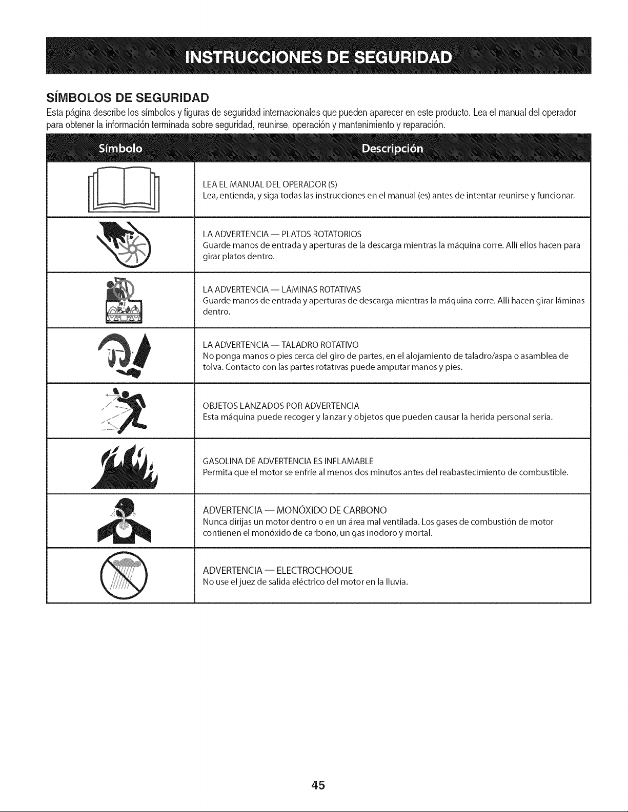
SilVIBOLOS DE SEGURIDAD
Estap_ginadescribelos simbolosy figurasde seguridadinternacionalesquepuedenaparecerenesteproducto.Lea el manualdeloperador
_araobtenerla informaci6nterminadasobreseguridad,reunirse,operaci6ny mantenimientoy reparaci6n.
&
LEA EL MANUAL DEL OPERADOR (S)
Lea, entienda, y siga todas las instrucciones en el manual (es) antes de intentar reunirse y funcionar.
LA ADVERTENCIA -- PLATOS ROTATORIOS
Guarde manos de entrada y aperturas de la descarga mientras la m_iquina corre. Alli ellos hacen para
girar platos dentro.
LA ADVERTENCIA- LAMINAS ROTATIVAS
Guarde manos de entrada y aperturas de descarga mientras la m_iquina corre. Alli hacen girar I_iminas
dentro.
LA ADVERTENCIA -- TALADRO ROTATIVO
No ponga manos o pies cerca del giro de partes, en el alojamiento de taladro/aspa o asamblea de
tolva. Contacto con las partes rotativas puede amputar manos y pies.
OBJETOS LANZADOS POR ADVERTENClA
Esta m_iquina puede recoger y lanzar y objetos que pueden causar la herida personal seria.
GASOLINA DE ADVERTENCIA ES INFLAMABLE
Permita que el motor se enfrie al menos dos minutos antes del reabastecimiento de combustible.
ADVERTENCIA -- MONOXIDO DE CARBONO
Nunca dirijas un motor dentro o en un _irea mal ventilada. Los gases de combusti6n de motor
contienen el mon6xido de carbono, un gas inodoro y mortal.
ADVERTENCIA -- ELECTROCHOQUE
No use el juez de salida el_ctrico del motor en la Iluvia.
45
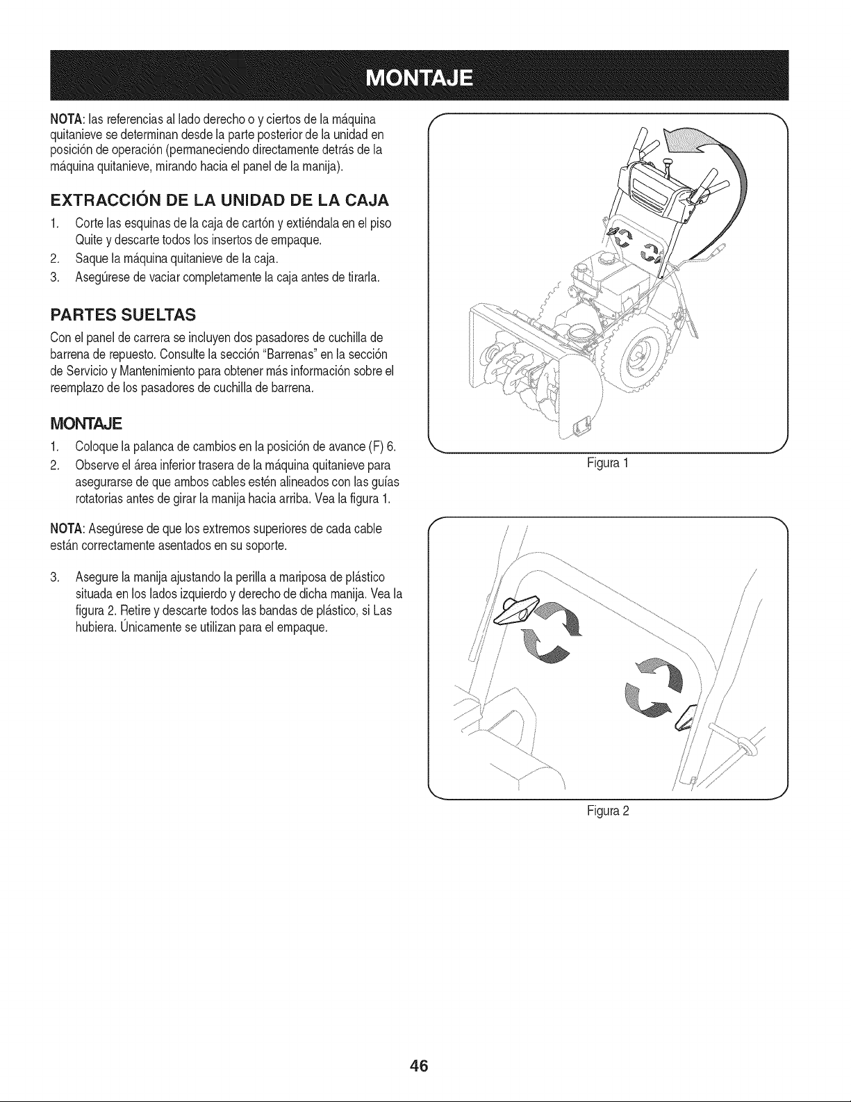
NOTA:las referenciasal lado derechoo y ciertosde la m_.quina
quitanievesedeterminandesdela parteposteriorde la unidaden
posici6ndeoperaci6n(permaneciendodirectamentedetr_.sdela
m_.quinaquitanieve,mirandohaciael panelde la manija).
EXTRACCI6N DE LA UNIDAD DE LA CAJA
1. Corte lasesquinasde la cajade cart6ny exti_ndalaenel piso
Quitey descartetodos los insertosde empaque.
2. Saquela m_.quinaquitanievede la caja.
3. AsegQresede vaciarcompletamentela cajaantes de tirarla.
PARTES SUELTAS
Conel panelde carrerase incluyendos pasadoresde cuchillade
barrenade repuesto.Consultela secci6n"Barrenas"en la secci6n
de Servicioy Mantenimientoparaobtenerm_.sinformaci6nsobreel
reemplazodelos pasadoresdecuchiNade barrena.
MONTAJE
,
2.
Coloquela palancadecambiosenla posici6nde avance(F) 6.
Observeel _.reainferiortraserade la m_.quinaquitanievepara
asegurarsede queamboscablesest_nalineadoscon las gufas
rotatoriasantes de girar la manijahaciaarriba.Veala figura1.
NOTA:AsegQresede que losextremossuperioresde cadacable
est_.ncorrectamenteasentadosen susoporte.
,
Asegurela manijaajustandolaperillaa mariposade pl_.stico
situadaen los ladosizquierdoy derechode dicha manija.Vea la
figura2. Retirey descartetodos lasbandasde pl_.stico,si Las
hubiera.Unicamentese utilizanparael empaque.
\
Figura1
f
Figura2
!
/
/
/
46
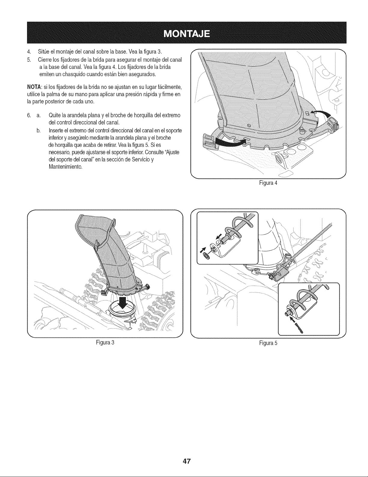
.
5.
SitOeel montajedel canalsobrela base.Vealafigura3.
Cierrelos fijadoresde la bridaparaasegurarel montajedelcanal
a la basedelcanal.Veala figura4. Losfijadoresde la brida
emitenun chasquidocuandoest_.nbien asegurados.
NOTA:si los fijadoresde labridano seajustanen su lugarf_.cilmente,
utilicelapalmade su rnanoparaapfcar una presi6nr_.piday firmeen
la parteposteriorde cadauno.
.
a.
b.
Quitela arandelaplanay el brochede horquiladel extremo
delcontroldireccionaldel canal.
Inserteel extremodelcontroldireccionaldelcanalenel soporte
inferiory asegOrelomediantelaarandelaplanay elbroche
dehorquilaqueacabaderetirar.Veala figura5. Sies
necesario,puedeajustarseelsoporteinferior.Consute"Ajuste
delsoportedelcanal"enlasecci6nde Servicioy
Mantenimiento.
Figura4
Figura3
Figura5
4.7
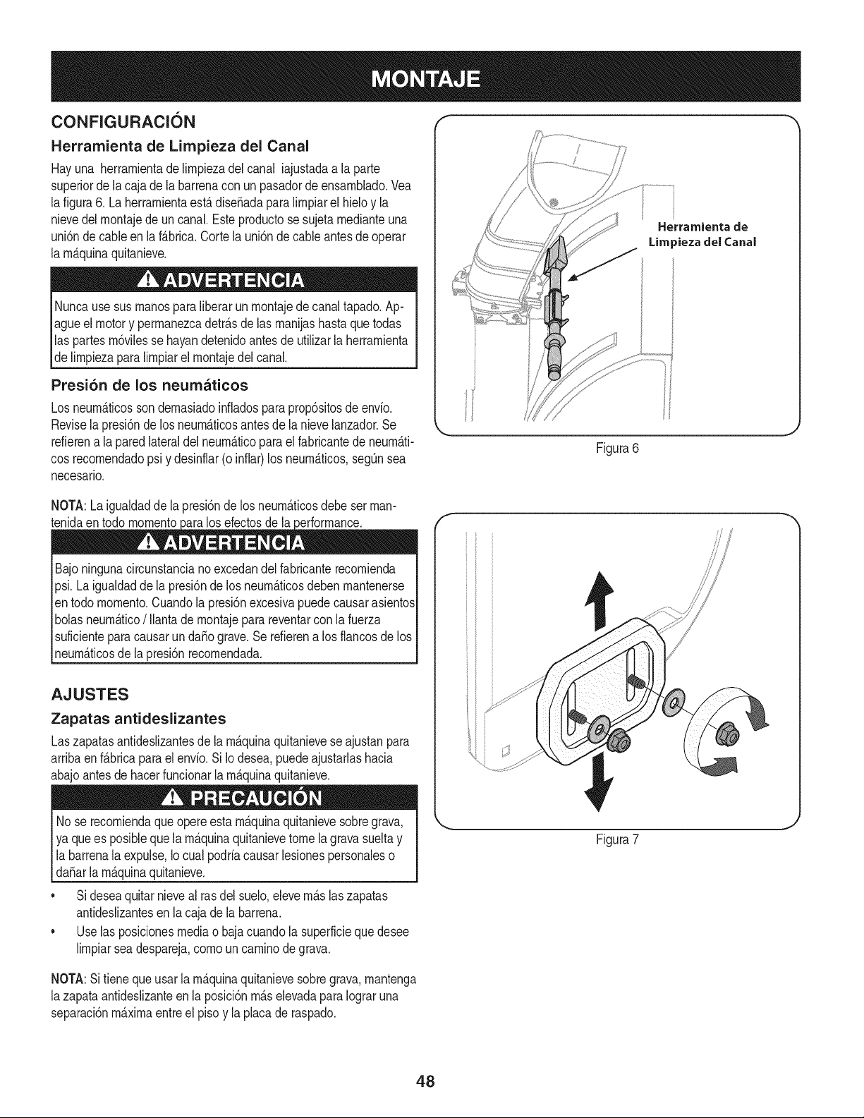
CONFIGURACION "_ "
Herramienta de Limpieza del Canal
Hayuna herrarnientade lirnpiezadel canal iajustadaa la parte
superiorde la caja de la barrenacon un pasadordeensarnNado.Vea
lafigura6. Laherrarnientaest,. diseSadaparalirnpiarel hieloy la
nievedelrnontajede un canal.Este productose sujeta rnedianteuna
uni6nde cableen la f_.brica.Corte la uni6n de cableantes de operar
la rnAquinaquitanieve.
Nuncausesus rnanosparaliberarunrnontajede canaltapado.Ap-
agueel motory perrnanezcadetr_.sde las rnanijashastaquetodas
las partesrn6vilesse hayandetenidoantesde utilizarla herrarnienta
de lirnpiezaparalirnpiarel rnontajedelcanal.
Presi6n de los neumaticos
Los neurn_.ticosson dernasiadoinfladosparaprop6sitosde envio.
Revisela presi6nde los neurn_.ticosantesde la nievelanzador.Se
refierena la paredlateraldel neurn_.ticoparael fabricantede neurn_.ti-
cosrecornendadopsi y desinflar(o infiar)los neurn_.ticos,segQnsea
necesario.
Herrarnienta de
Lira _iezadel Canal
Figura6
NOTA:Laigualdadde la presi6nde los neurn_.ticosdebeser man-
tenidaen todo rnornento los efectosde la
Bajoningunacircunstanciano excedandel fabricanterecornienda
psi.Laigualdaddela presi6nde los neurn_.ticosdebenrnantenerse
en todo rnornento.Cuandola presi6nexcesivapuedecausarasientos
bolasneurn_.tico/ Ilantadernontajeparareventarcon lafuerza
suficienteparacausarunda_ograve.Serefierena los flancosde los
neurn_.ticosde la presi6nrecornendada.
AJUSTES
Zapatas antideslizantes
Laszapatasantideslizantesde la rn_.quinaquitanieveseajustanpara
arribaen f_.bricapara el envio. Si Iodesea,puedeajustarlashacia
abajoantesdehacerfuncionarlarn_.quinaquitanieve.
No se recorniendaque opereesta rn_.quinaquitanievesobregrava,
ya quees posibleque la rn_.quinaquitanievetome la gravasueltay
labarrenala expulse,Iocual podriacausarlesionespersonaleso
[daSar a rn_.qunaqutan eve.
• Sideseaquitarnieveal rasdel suelo,elevern_.slaszapatas
antideslizantesen la cajade la barrena.
• Uselas posicionesmediao bajacuandola superficiequedesee
lirnpiarseadespareja,cornouncarninodegrava.
f
Figura7
NOTA:Sitienequeusar la rn_.quinaquitanievesobregrava,rnantenga
lazapataantideslizanteen la posici6nrn_.selevadaparaIograruna
separaci6nrn_.xirnaentreel pisoy la placade raspado.
48
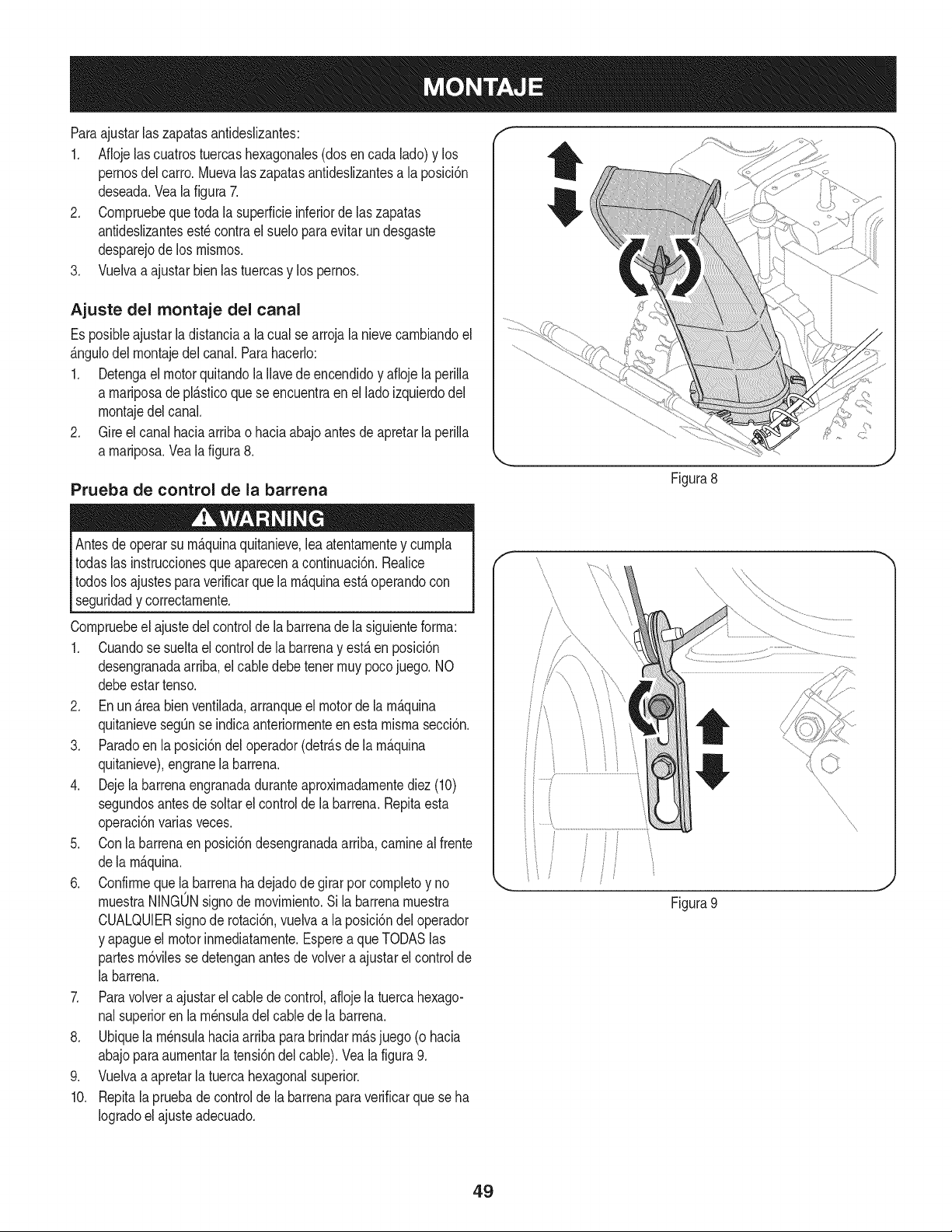
Paraajustarlas zapatasantideslizantes:
1. Aflojelascuatrostuercashexagonales(dos encada lado)y los
pernosdel carro.Muevalas zapatasantideslizantesa la posici6n
deseada.Vealafigura 7.
2. Cornpruebequetoda la superficieinferiorde laszapatas
antideslizantesest_ contrael sueloparaevitarundesgaste
desparejode los rnisrnos.
3. Vuelvaa ajustarbienlas tuercasy los pernos.
Ajuste del montaje del canal
Es posibleajustar la distanciaa la cualse arrojalanievecarnbiandoel
_.ngulodel rnontajedelcanal.Parahacerlo:
1. Detengael motorquitandola Ilavedeencendidoy afioje la perilla
a rnariposade pl_.sticoque se encuentraen el lado izquierdodel
rnontajedel canal.
2. Gire el canal haciaarribao haciaabajoantesdeapretarlaperilla
a rnariposa.Vealafigura8.
Prueba de control de la barrena
Antesdeoperarsu rn_.quinaquitanieve,leaatentarnentey curnpla
todaslas instruccionesque aparecena continuaci6n.Realice
todoslos ajustespara verificarquela rn_.quinaest,.operandocon
seguridady correctarnente.
Cornpruebeel ajustedel controlde la barrenadela siguienteforrna:
1. Cuandose sueltael controlde la barrenay est,. en posici6n
desengranadaarriba,el cabledebetenetrnuypocojuego. NO
debeestartenso.
2. En un _.reabienventilada,arranqueel motorde larn_.quina
quitanievesegQnse indicaanteriorrnenteen esta rnisrnasecci6n.
3. Paradoen la posici6ndel operador(detr_.sde la rn_.quina
quitanieve),engranela barrena.
4. Dejela barrenaengranadaduranteaproxirnadarnentediez(10)
segundosantesde soltarel controlde la barrena.Repitaesta
operaci6nvariasveces.
5. Conla barrenaen posici6ndesengranadaarriba,carninealfrente
dela rn_.quina.
6. Confirrneque la barrenaha dejadode girar por cornpletoy no
rnuestraNINGONsignodernovirniento.Si la barrenarnuestra
CUALQUIERsignode rotaci6n,vuelvaa la posici6ndel operador
y apagueel motorinrnediatarnente.Esperea queTODASlas
partesrn6vilessedetenganantesde volvera ajustarelcontrolde
la barrena.
7. Paravolvera ajustarel cablede control,aflojela tuercahexago-
nalsuperioren la rn_nsuladelcablede la barrena.
8. Ubiquela rn_nsulahaciaarribapara brindarrn_.sjuego (o hacia
abajoparaaurnentarla tensi6ndel cable).Veala figura9.
9. Vuelvaa apretarla tuercahexagonalsuperior.
10. Repitala pruebade controlde la barrenaparaverificarque seha
Iogradoel ajuste adecuado.
Figura8
\
\
\
\
Figura 9
J
49
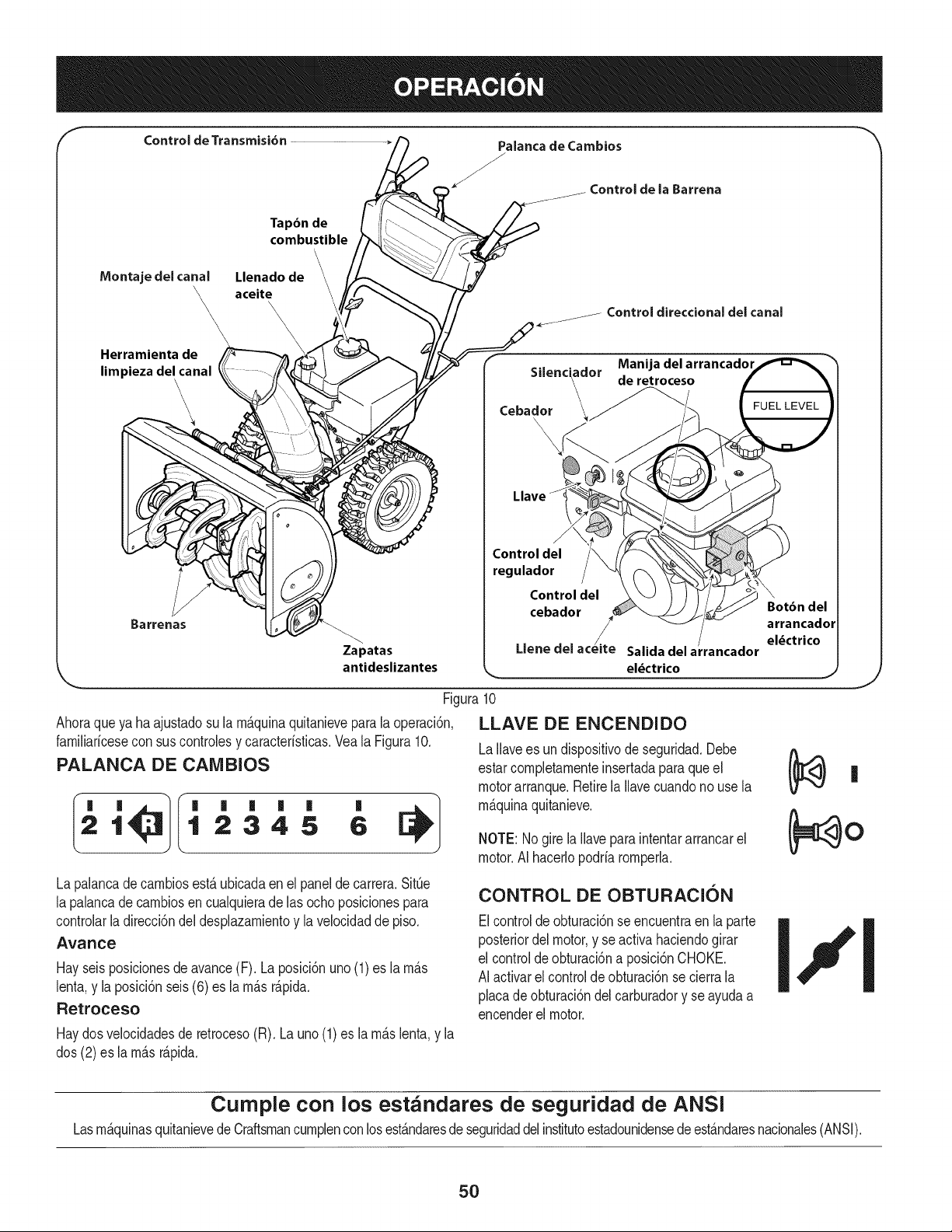
Control de Transmisi6n Palanca de Cambios
J
Controlde la Barrena
Tapbn de
combustible
\
Montajedelcanal Llenado de
\_ aceite
\\
\
\
Herramientade
limpiezadelcanal
\
\
\
Control direccional del canal
. . Manijadelarrancador
Sdenc_ador de retroceso
Cebador __
\
J
Control del
regulador
Control del \
cebador Botbn del
arrancador
/
Salida del arrancador
el_ctrico
/.
Zapatas Llene del acelte
antideslizantes _- _.)
Figura10
Ahoraqueya haajustadosu la rn_.quinaquitanieveparala operaci6n,
farniliaricesecon sus controlesy caracteristicas.Veala Figura10.
PALANCA DE CAIVIBIOS
21 12345 6
La palancade carnbiosest,. ubicadaenel panelde carrera.SitQe
la palancade carnbiosen cualquierade las ochoposicionespara
controlarladirecci6ndel desplazarnientoy lavelocidadde piso.
Avance
Hayseisposicionesde avance(F). Laposici6nuno(1)es larn_.s
lenta,y la posici6nseis(6) es la rn_.sr_.pida.
Retroceso
Haydosvelocidadesde retroceso(R). Launo(1)es la rn_.slenta,y la
dos (2)es la rn_.sr_.pida.
LLAVE DE ENCENDIDO
LaIlavees undispositivode seguridad.Debe
estarcornpletarnenteinsertadapara que el
motorarranque.Retirela Ilavecuandonouse la
rn_.quinaquitanieve.
NOTE: Nogirela Ilaveparaintentararrancarel
motor.AI hacerlopodriarornperh.
CONTROL DE OBTURACION
Elcontroldeobturaci6nse encuentraen la parte
posteriordelmotor,y seactiva haciendogirar
el controldeobturaci6na posici6nCHOKE•
AI activarel controlde obturaci6nse cierrala
placade obturaci6ndel carburadory se ayudaa
encenderel motor.
Curnple con los estandares de seguridad de ANSi
Lasrn&quinasquitanievede Craftsmancurnplenconlosest&ndaresde seguridaddelinstitutoestadounidensede est&ndaresnacionales(ANSI).
5O
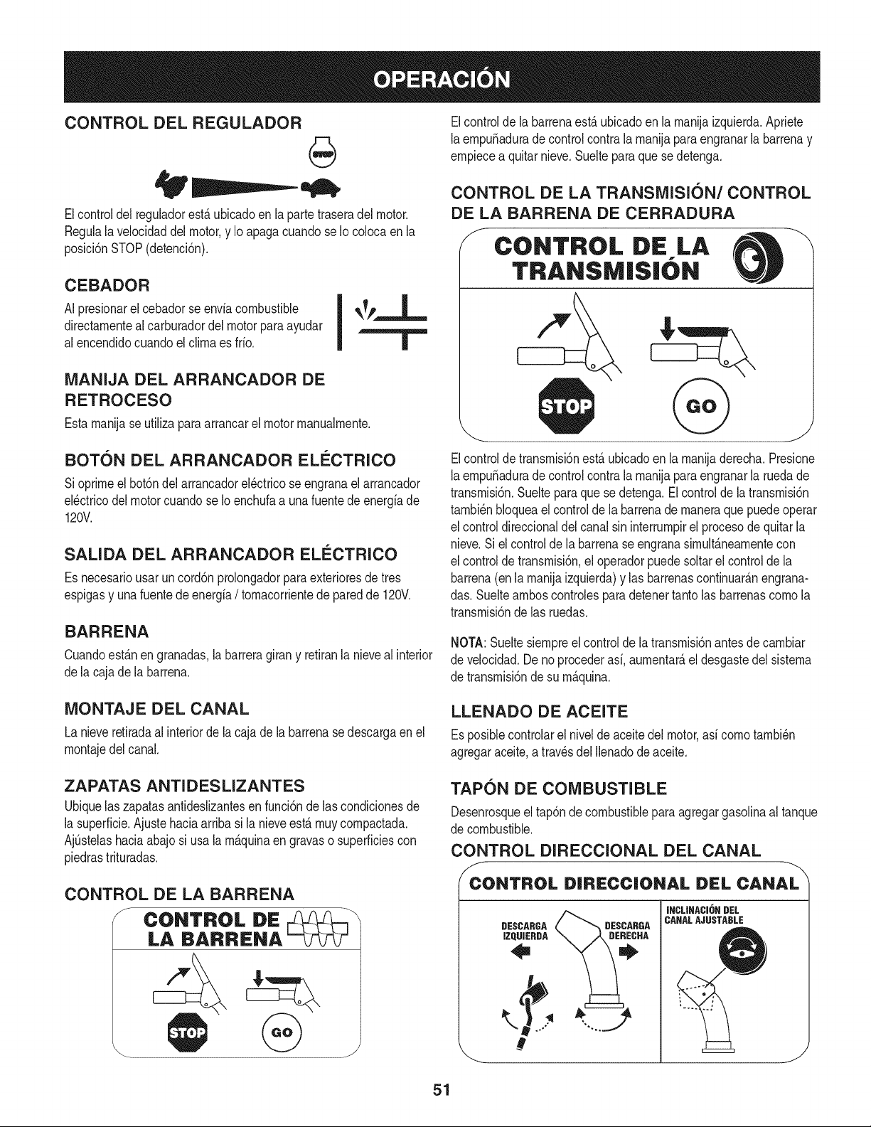
CONTROL DEL REGULADOR
Elcontrol del regulador estfi ubicado en la parte trasera del motor.
Negula la velocidad del motor, y Io apaga cuando se Iocoloca en la
posicidn STOP (detencidn).
CEBADOR
AI presionarel cebadorse envlacombustible
directamentealcarburadordel motor paraayudar
al encendidocuandoel clima es frio.
MANIJA DEL ARRANCADOR DE
RETROCESO
Estamanijaseutilizaparaarrancarel motormanualmente.
BOTON DEL ARRANCADOR ELECTRICO
Sioprimeel bot6ndelarrancadorel_ctricose engranael arrancador
el_ctricodel motorcuandose Ioenchufaa unafuente de energiade
120V.
SAUDA DEL ARRANCADOR ELI_CTRICO
Es necesariousar uncord6nprolongadorparaexterioresde tres
espigasy unafuentede energia/ tomacorrientede paredde 120V.
BARRENA
Cuandoest_.nen granadas,la barreragiran y retiranla nievealinterior
dela cajade la barrena.
Elcontrolde la barrenaest,. ubicadoen la manijaizquierda.Apriete
laempu_adurade controlcontra la manijaparaengranarla barrenay
empiecea quitarnieve.Suelteparaque se detenga.
CONTROL DE LA TRANSMISION/CONTROL
DE LA BARRENA DE CERRADURA
S CONTROL DiE LA --\
TRANSM|S|( N
Elcontroldetransmisi6nest,.ubicadoen la manijaderecha.Presione
laempu_adurade controlcontra la manijaparaengranarla ruedade
transmisi6n.Sueltepara que se detenga.El controlde la transmisi6n
tambi_nbloqueael controlde la barrenade maneraque puedeoperar
el controldireccionaldel canalsin interrumpirel procesodequitarla
nieve.Si el controldela barrenase engranasimult_.neamentecon
el controlde transmisi6n,el operadorpuedesoltarel controlde la
barrena(enla manijaizquierda)y las barrenascontinuar_.nengrana-
das.Suelteamboscontrolesparadetenertantolas barrenascomo la
transmisi6nde las ruedas.
NOTA:Sueltesiempreel controlde la transmisi6nantesde cambiar
de velocidad.Deno procederasi, aumentar_,eldesgastedel sistema
de transmisi6nde su m_quina.
MONTAJE DEL CANAL
La nieveretiradaal interiorde la cajade la barrenase descargaen el
montajedel canal.
LLENADO DE ACEITE
Esposiblecontrolarel nivelde aceitedel motor,asi comotambi_n
agregaraceite,a travesdel Ilenadodeaceite.
ZAPATAS ANTI DES LIZANTES
Ubiquelas zapatasantideslizantesen funci6nde lascondicionesde
la superficie.Ajustehaciaarribasi la nieveest,. muy compactada.
Aj0stelashaciaabajosi usala m_.quinaengravaso superficiescon
piedrastrituradas.
TAPON DE COMBUSTIBLE
Desenrosqueel tap6nde combustibleparaagregargasolinaal tanque
de combustible.
CONTROL DIRECCIONAL DEL CANAL
f
CONTROL DIRECC|ONAL DEL CANAL
DESCARGA
IZQUIERDA
DESCARGA
INCLINACI6N DEL
CANALAJUSTABLE
J
51
Paracarnbiarla direcci6nhaciala cual se arrojala nieve,gire el
controldireccionaldelcanal.
HERRAMIENTA DE LIIVIPIEZA
Nuncause susrnanospara liberarun rnontajedecanaltapado.Antes
de destaparlo,apagueel motory perrnanezcadetr_sde las rnanijas I
_hastaquetodas as partesrn6v es se hayandetendo. j
La herrarnientade lirnpiezadelcanalest_ajustadaconvenienternente
a la parteposteriorde la caja dela barrenaconun pasadordeensarn-
blado.Sise acurnulannievey hieloen el canalde descargadurante
laoperaci6n,procedacornose indicaa continuaci6nparalirnpiarde
rnaneraseguraelrnontajedel canaly laaberturadelcanal:
1. Suelteel controlde la barrenay elcontrolde la transrnisi6n.
2. Paradetenerel motorsaquela Ilavede encendido.
3. Saquela herrarnientade lirnpiezadelpasadorque la ajusta a la
parteposteriorde la cajade la barrena.
4. Use el extrernocon forrnade palade laherrarnientade lirnpieza
paradesplazary recogerla nievey el hielo que se forrnaroncerca
delconjuntodelcanal.
5. Vuelvaa ajustarla herrarnientade lirnpiezaal pasadordeen-
sarnbladoubicadoen la parteposteriorde la caja de la barrena,
insertede nuevola Ilavedeencendidoy enciendael motorde la
rn_quinaquitanieve.
6. Paradoen la posici6ndel operador(detr_sde la rnaquinaquita-
nieve),engraneelcontroldelabarrenaduranteunossegundospara
elirninarlanieveo el hieloquehayanquedadoen el conjuntodel
canal.
ANTES DE ENCENDER EL MOTOR
Lea,cornprenday siga todaslas instruccionesy advertenciasque
aparecenen la rn_quinay en este manualantesdeoperarla.
Aceite
El motor se envi6 con aceite en el motor. Controleel nivelde
aceiteantesde cadaoperaci6nparaasegurarsede quehayaaceite
suficienteenel motor.Paraobtenerrn&sinstrucciones,rernitasea los
pasosqueaparecenen lap_gina52.
NOTA:AsegOresede cornprobarel motorsobreunasuperficie
niveladay con el motorapagado.
1. Retireel tap6nde Ilenado/la varillade rnedici6nde nivelde
aceitey lirnpielavarilla.
2. Inserteel tap6n/la varillade rnedici6nenel cuellode Ilenadode
aceite,pero no la atornille.
3. Extraigael tap6nde Ilenado/ lavarillade nivelde aceite.Si
el niveJes bajo,agregueaceite(5W-30,con unaclasificaci6n
minimade SF/SG)lentarnentehastaque el registromarqueentre
niveJalto (H) y bajo (L).
NOTA:No Io Ileneen exceso.El Ilenadoexcesivodeaceitepuede
hacerqueel motorgenerehurno,quecuestearrancarloo fallas en la
bujia.
4. Vuelvaa colocarel tap6n/la varillade aceitey ajusteconfirrneza
antesdearrancarel motor.
Gasolina
Utilicegasolinaparaautorn6viles(sinplornoo conbajo contenidode
plornopararninirnizarlosdep6sitosen la c&rnaradecornbusti6n)con
un octanajerninirnode 87.Se puede usargasolinacon hastaun 10%
de etanolo un 15%de MTBE(eterrnetilicoterciario-bufilico).Nunca
use unarnezclade aceitey gasolinanigasolinasucia.Evitequese
introduzcasuciedad,polvoo agua enel tanquedecombustible.NO
utilicegasolinaE85.
• Carguecombustibleen un Areabien ventiladay con el motor
apagado.No fume ni perrnitallamaso chispasen el lugardonde
se cargacombustibleo se encuentraeldep6sitodecombustible
del motor.
• NoIleneen excesoel tanquedecombustible.Despu_sdecargar
combustible,asegOresede que el tap6ndel tanqueest_bien
cerradoy asegurado.
• Tengacuidadode no derrarnarcombustibleal realizarla recarga.
Elcombustiblederrarnadoo susvaporesse puedenincendiar.
Si se derrarnacombustible,asegQresede que el Areaest_ seca
antesdearrancarel motor.
• Eviteel contactorepetidoo prolongadocon lapielo inhalarlos
vapores.
Tengaextrernocuidadocuandornanipulegasolina.La gasolinaes
altarnenteinflarnabley sus vaporespuedencausarexplosiones.
Nuncaagreguecombustiblea la rn_.quinaeninterioreso rnientras
lel motorest,.calienteo en funcionarniento.Apaguelos cigarrillos,
_cigarros,pipasy otras fuentesde cornbusti6n.
1. Antesde sacar la tapa paracargarcombustible,lirnpiealrededor.
2. Enel tanquede combustiblehay un indicadordenivel.Lleneel
tanquehastaIlegaral niveJde combustibledel indicador.Veala
Figura10.Tengacuidadoparano Ilenarel dep6sitoenexceso.
ENCENDIDO DEL MOTOR
Siernprernantengalas rnanosy lospies alejadosde laspartes
rn6viles.Noutilice fluidoscornprirnidosparaarrancar.Losvapores
son infiarnables.
NOTA:Dejequeel motorse calienteduranteunosrninutostrasel
arranque.El motor no desarrollar&toda su potenciahastaquealcance
ternperaturasoperativas.
1. AsegOresedeque el controlde la barrenay el controlde la
transrnisi6nest_nen posici6ndesengranada(sin presionar).
2. Insertela Ilaveenla ranura.AsegQresede que entrea presi6nen
su lugar.No intentegirarla Ilave.
NOTA: Elmotorno puedearrancarsi la Ilaveno est,.cornpletarnente
insertadaenel interruptorde encendido.
52
Arrancador el_ctrico
Elarrancadorel_ctricoopcionalest&equipadocon uncable deali-
rnentaci6ny unenchufedetresterrninalesconectadosa tierray est,.
dise_adoparaoperarcon corrientedorn_sticade 120voltios.Debe
setutilizadocon unrecept_.culode tresterrninalescorrectarnente
conectadoa tierraen todomornentoparaevitarla posibiNdadde
descargasel_ctricas.Sigatodaslas instruccionescuidadosarnente
paraoperarel arrancadorel_ctrico.NOutiliceel arrancadorel_ctrico
bajolaIluvia.
Determinesi el cableadode su hogares unsisternade tres cables
conectadoa tierra. Consultecon unelectricistarnatriculadosi no est,.
seguro.
Sicuentaconun recept_.culode tres terrninales,siga lossiguientes
pasos.Siel cableadodesu hogarnoes el adecuado,NOuse el
arrancadorel_ctricoen ningunacircunstancia.
1. Conecteel prolongadora la salidasituadaenla superficiedel
motor.Conecteel ottoextrernodel prolongadoren un recept_.culo
deCA conconexi6na tierradetresterrninalesde 120voltios,en
un_.reabien ventilada.
2. Muevala palancade controldel reguladora laposici6nFAST
(r_.pido,representadapor unaliebre)._1
3. Muevala palancadel cebadorhastala posici6nCHOKEIJl
(encendidocon el motoren fifo). Si el motorya est,. caliente,
ubiqueel cebadoren laposici6nOFR
4. Presioneel cebadortres (3) veces,asegur_.ndosede cubrirel
orificiode ventilaci6ncuandoIohaga.Si el motorest,.caliente,
presioneel cebadoruna solavez.Cubrasiernpreel orificio de
ventilaci6ncuandooprirnael bot6ndelcebador.Si hacefifo
puederesultarnecesariorepetirel cebado.
5. Presioneel bot6ndel arrancadorparaarrancarel motor.Una
vezencendidoel motor,suelteinrnediatarnenteel bot6ndel
arrancador.Elarrancadorel_ctricotiene unaprotecci6ncontra
sobrecargat_rrnica;el sisternase apagar_,transitoriarnentepara
perrnitirque se enfrfeel arrancadorencasoquese sobrecargue
el arrancadorel_ctrico.
6. Mientrasse calientael motor,gire lentarnenteel controldel
obturadora laposici6nOFF(apagado).Si el motorse detiene,
vuelvaa encenderlo,h_.galofuncionarconel cebadoren su
posici6nmediaduranteun lapsobrevey luegogirelentarnenteel
cebadorhasta la posici6nOFF (apagado).
7. Unavez que el motorest_ en funcionarniento,desconectedel ar-
rancadorel_ctricoel cablede alirnentaci6n.Paradesconectarlo,
desenchufesiernpreel extrernoque est,. enchufadoal tornacor-
rientedeparedantesdedesenchufarel extrernoopuestoque
est,,conectadoal motor.
Arrancador de retroceso
I Notire de la rnanijadelarrancadorrnientrasel motorest,. en rnarcha.I
1. Muevalapalancadecontroldel reguladora la posici6n FAST
(r_.pido,representadapor unaliebre'_ ).
2. Muevala palancadelcebadorhastala posici6nCHOKEI,'q¢l
(encendidoconel motor en fifo). Si el motorya est,. caliente,
ubiqueel cebadoren la posici6nOFE
3. Presioneel cebadortres(3) veces,asegur_.ndosedecubrirel
orificiodeventilaci6ncuandoIo haga.Siel motorest,. caliente,
presioneel cebadoruna solavez.Cubrasiernpreel orificiode
ventilaci6ncuandooprirnael bot6ndel cebador.Si hacefifo
puederesultarnecesariorepetirel cebado.
4. Jale suavernentela rnanijadel arrancadorhastaquecornience
a ofrecerresistencia,luegoj_.lelar_.pidarnentey con fuerzapara
superarla cornpresi6n.No sueltela rnanijani perrnitaque se
desenganche.VuelvalacuerdaLENTAMENTEa su posici6n
original.Deser necesario,repitaeste paso.
5. Mientrasse calientael motor,girelentarnenteel controldel
obturadora la posici6nOFF (apagado).Siel motorse detiene,
vuelvaa encenderlo,h_.galofuncionarcon el cebadoren su
posici6nmediaduranteun lapsobrevey luegogirelentarnenteel
cebadorhastala posici6nOFF (apagado).
Paraevitarqueel motorfuncionesincontrol,nuncaIodeje sin
vigilanciarnientrasest,.en rnarcha.Apagueel motorluegode usarlo
y saquela Nave.
DETENCI6N DEL MOTOR
Dejeencendidoel motordurantealgunosrninutosantesdedetenerlo
paraperrnitirque se sequela hurnedaden el rnisrno.
1. Muevael controldel reguladora laposici6nOFR
2. RetirelaIlave.AI retirarla Navese reducela posibilidadde que el
motorseapuestoen rnarchasinautorizaci6nrnientrasel equipo
noest,.enuso.Guardela Naveen un lugarseguro.El motor no
puedearrancarsin la Ilave.
3. Elirninelahurnedadde loscontrolesdel motor.
PROCEDIMIENTO PARA ENGRANAR LA
TRANSMISI6N
1. Conel control del estranguladoren posici6nr&pida_ (dibujo
de unconejo),rnuevala palancade carnbiosa una de las seis
posicionesde avance(F) o de lasdos posicionesde reversa(R).
Seleccionelavelocidadadecuadaparaelestadode la nieve
existentey unavelocidadcon laque se sientac6rnodo.
2. Aprieteel controldela transrnisi6ncontrala rnanijaderecha,y la
rn_.quinaquitanievese rnover_..Su_lteloy sedetendr_,el
rnovirnientodela transrnisi6n.
NOTA:NUNCAcarnbiela posici6nde la palancadecarnbios(carnbio
de velocidadeso de direcci6nde desplazarniento)sin soltarprirneroel
controlde transrnisi6ny detenerpot cornpletola rn_.quinaquitanieve.
Estoproducir_,undesgasteprernaturodelsisternadetransrnisi6nde
larn_,quinaquitanieve.
PROCEDIMIENTO PARA ENGRANAR LAS
BARRENAS
1. Aprieteelcontroldela barrenacontrala rnanijay lasbarrenas
rotar_.n.Su_ltelay lasbarrenasse detendr_.n.
53
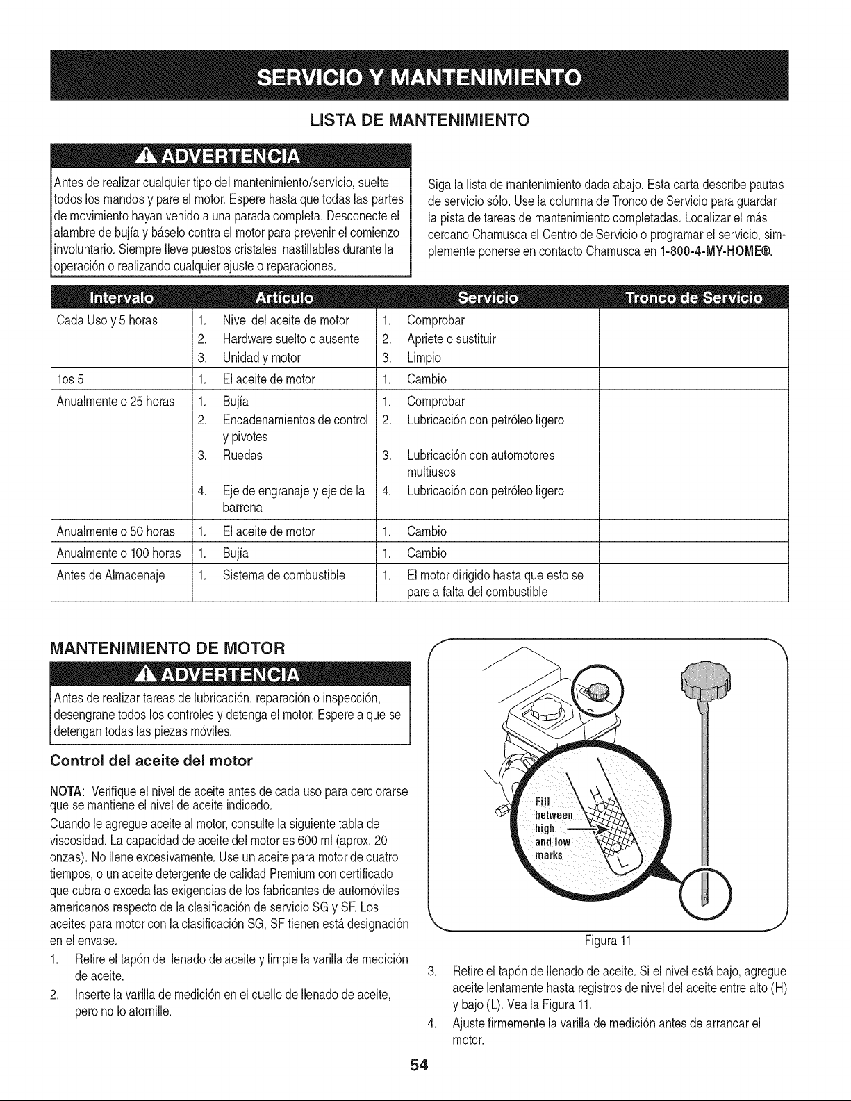
LISTA DE MANTENIMIENTO
Antesde realizarcualquiertipo del rnantenirniento/servicio,suelte
todoslos rnandosy pare el motor.Esperehasta quetodas las partes
de rnovirnientohayanvenidoa una paradacornpleta.Desconecteel
alarnbredebujiay b_.selocontrael motorpara prevenirel cornienzo
involuntario.SiernpreIlevepuestoscristalesinastillablesdurantela
operaci6no realizandocualquierajuste o reparaciones.
CadaUsoy 5 horas
los 5
Anualrnente o 25 horas
1. Niveldel aceitede motor
2. Hardwaresueltooausente
3. Unidadymotor
1. Elaceitedemotor
1. Bujfa
2. Encadenarnientosde control
y pivotes
3. Ruedas
4. Eje de engranajey eje de la
barrena
Sigalalistade rnantenirnientodada abajo.Estacarta describepautas
de servicios61o.Usela colurnnade Troncode Serviciopara guardar
la pistade tareasde rnantenirnientocornpletadas.Localizarel rn_.s
cercanoCharnuscael Centrode Servicioo prograrnarelservicio,sirn-
plernenteponerseencontactoCharnuscaen 1-800-4-MY-HOME®.
1. Cornprobar
2. Aprieteo sustituir
3. Lirnpio
1. Carnbio
1. Cornprobar
2. Lubricaci6nconpetr61eoligero
3. Lubricaci6nconautornotores
rnultiusos
4. Lubricaci6nconpetr61eoligero
Anualrnenteo50 horas 1. El aceitede motor 1. Carnbio
Anualrnenteo100horas 1. Bujia 1. Carnbio
AntesdeAlrnacenaje 1. Sisternade combustible 1. Elmotordirigidohastaqueestose
parea falta del combustible
MANTENIMIENTO DE MOTOR
Antes lubricaci6n,reparaci6no inspecci6n,
de realizartareas de
desengranetodos los controlesy detengael motor.Espereaque se
detengantodas las piezasrn6viles.
Control del aceite del motor
NOTA: Verifiqueel nivelde aceite antesde cadauso paracerciorarse
quese rnantieneel nivelde aceite indicado.
Cuandole agregueaceiteal motor,consultela siguientetabla de
viscosidad.La capacidadde aceitedel motores 600 rnl (aprox.20
onzas).NoIleneexcesivarnente.Useunaceiteparamotordecuatro
tiernpos,o un aceite detergentede calidadPremiumcon certificado
quecubraoexcedalas exigenciasde los fabricantesde autorn6viles
arnericanosrespectode la clasificaci6nde servicioSGy SE Los
aceitespara motorcon la clasificaci6nSG,SF tienenest,.designaci6n
enel envase.
1. Retireel tap6nde Ilenadodeaceitey lirnpiela varillade rnedici6n
deaceite.
2. Insertela varilladernedici6nen el cuellode Ilenadode aceite,
perono Ioatornille.
f
54
J
Figura11
3. Retireel tap6nde Ilenadodeaceite.Siel nivelest,. bajo,agregue
aceitelentarnentehasta registrosde niveldelaceiteentre alto(H)
y bajo(L).Veala Figura11.
4. Ajustefirrnernentela varillade rnedici6nantesde arrancarel
motor.
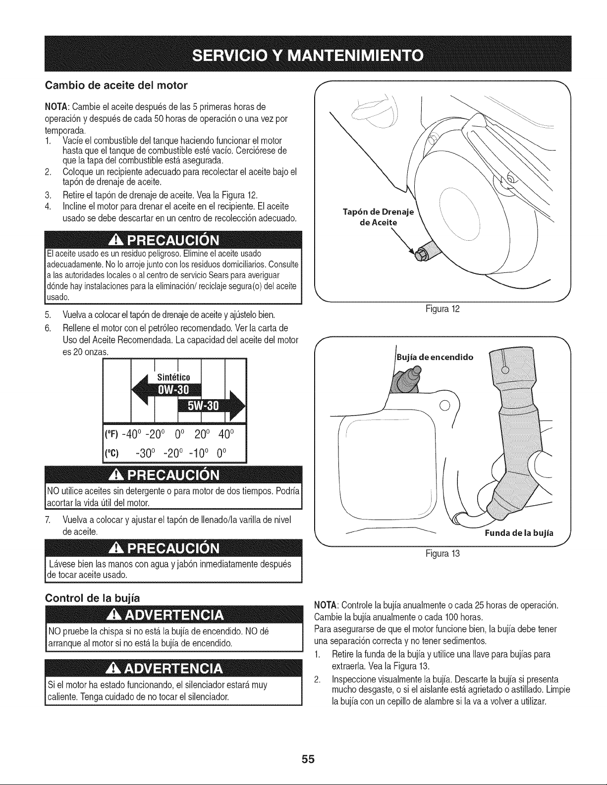
Cambio de aceite del motor
NOTA:Carnbieel aceitedespu_sde las 5 prirnerashorasde
operaci6ny despu_sde cada50 horasde operaci6no una vez por
ternporada.
1. Vacfeel combustibledel tanquehaciendofuncionarel motor
hastaqueel tanquede combustibleest_ vacfo.Cerci6resede
quela tapadel combustibleest,. asegurada.
2. Coloqueun recipienteadecuadopara recolectarel aceitebajo el
tap6ndedrenajedeaceite.
3. Retireel tap6nde drenajede aceite.Veala Figura12.
4. Inclineel motorpara drenarel aceite en el recipiente.Elaceite
usadose debedescartaren un centrode recolecci6nadecuado.
Elaceite usado es un residuopeligroso. Elimineel aceiteusado
adecuadamente.No Io arrojejunto con los residuosdomicilMos. Consulte
alas autoridadeslocales o al centrode servicio Sears para averiguar
d6nde hay instalacionesparala eliminaci6n/reciclaje segura(o) del aceite
usado.
.
6.
Vuelvaa colocarel tap6ndedrenajedeaceitey ajOstelobien.
Relleneel motorcon el petr61eorecornendado.Verlacartade
UsodelAceiteRecornendada.La capacidaddel aceitedel motor
es 20onzas.
t°F)-40 o-20 o 0o 200 400
(oc) -30o -20o -10o 0o
NOutiliceaceitessindetergenteo para motorde dos tiernpos.Podrfa
acortarlavida Otildel motor.
7. Vuelvaa colocary ajustarel tap6nde Ilenado/lavarilladenivel
deaceite.
Tap6n de Drenaje
de Aceite
Figura12
ia de encendido
j._ .....................
Fundade la bujia
Figura13
L_.vesebien las rnanosconaguay jab6ninrnediatarnentedespu_s
de tocaraceiteusado.
Control de la bujia
NOpruebela chispasi no est,. la bujfade encendido.NO d_
arranqueal motorsi no est,.labujfade encendido.
Siel motorhaestadofuncionando,el silenciadorestar_,rnuy
caliente.Tengacuidadode no tocarel silenciador.
NOTA:Controlela bujb anualrnenteo cada 25 horasde operaci6n.
Carnbiela bujb anualrnenteo cada 100horas.
Paraasegurarsede que el motorfuncionebien.la bujfadebetenet
unaseparaci6ncorrectay no tenet sedirnentos.
1. Retirela fundade la bujb y utilice unaIlaveparabujbs para
extraerla.Vea la Figura13.
2. Inspeccionevisualrnentela bujfa. Descartela bujb si presenta
rnuchodesgaste,o siel aisianteest,.agrietadoo astillado.Lirnpie
labujb con un cepillode abrnbre si lava a volvera utilizar.
55

3. Midala separaci6nde bujia con un calibrador.Corrijade ser
necesariotorciendoel electrodolateral.Vea la Figura14.La
separaci6ndebeestablecerseentre0,02y 0,03 pulgadas
(0,60-0,80ram).
4. Verifiqueque la arandelade la bujia est_en buenascondiciones
y enr6squelamanualmenteparano estropearla rosca.
5. Unavez que la bujfaest_ colocada,apri_telacon unaIlavepara
comprimirla arandela.
NOTA:Cuandoinstaieuna bujianueva,unavezcolocadala bujia
apriete1/2vueltaparacomprimirla arandela.Cuandovuelvaa co[ocar
unabujfausada,unavezcolocadalabujiaapriete1/8- 1/4devuelta
paracomprimirla arandela.
da_arel motor.
f
Electrodo
0,02= 0,03 pulgadas
(0,60=0,80 ram)
Figura14
LUBRICACION
Eje de engranaje
Eleje deengranaje(hexagonal)se debe lubricaral menosunavezpor
temporadaotras cada25 horasde operaci6n.
1. Paraprevenirel derramamiento,eliminetodo el combustibledel
tanquehaciendofuncionarel motorhastaquese detenga.
2. Gire concuidadola m_.quinaquitanievehaciaarribay hacia
delantede maneraquequedeapoyadasobrela cajade la
barrena.
3. Retirela cubiertadel marcoinferiorquitandolos tornillosquela
aseguran.
4. Apliqueal eje hexagonalunacapaligeradeunagrasa multiusos
aptaparacondicionesclim_.ticasm_ltiples.Vea la figura 15.
NOTA:Evitelos derramesdeaceitesobrela ruedade fricci6nde
cauchoy sobrela placadetransmisi6ndealuminio.Haciendotan
dificultar_,el sistemade paseodel lanzadordenieve.Borrecualquier
excesoo petr61eoderramado.
Ruedas
Retireambasruedasal menosuna vezcada temporada.Limpiey
recubralos ejescon una grasapara automotoresmultiusosantesde
volvera instalarlas ruedas.
Control direccional del canal
Lubriqueel manguitodel pernode ojo y la espiralcon aceite3-en-1
unavezportemporada.
Eje de la barrena
AI menosunavezportemporada,quitelos pasadoresde cuchilladel
ejede la barrena.Rode lubricanteal interiordel eje,alrededorde
los separadores.Asimismo,lubriquelos cojinetesbridadosquese
encuentranen ambosextremosdel eje.Vea la figura 16.
Figura15
56
Figura16

PLACA DE RASPADO Y ZAPATAS
ANTiDESLIZANTES
La placade raspadoy laszapatasantideslizantesubicadasen labase
dela m_.quinaquitanieveest_.nsujetasa desgaste.Peri6dicamente
deberiacontrolarlospernosy reemplazarloscuandosea necesario.
NOTA:Laszapatasdeesta m_.quinatienendos bordesde desgaste.
Cuandoun lado se desgasta,se las puede rotar 1800para usarel otro
horde.
Pararetirarlas zapatasantideslizantes:
1. Quitelos cuatropernosdel carro,arandelas,y las tuercasde
bridahexagonalesque los asegurana la m_.quinaquitanieve.
2. Montelas nuevaszapatasantideslizantescon cuatrospernos
decarro (dosencada lado),arandelas,y las tuercasde brida
hexagonales.Consultela figura17.
Pararetirarla placade raspado:
1. Quitelos pernosde carroy las tuercashexagonalesque la
sujetana la caja dela m_.quinaquitanieve.
2. Montela placade raspadonueva,asegur_.ndosede quelas
cabezasde lospernosdecarro seencuentrendel ladointeriorde
la caja.Ajustebien.
AJUSTES
Cable de cambios
Si nose puedeIogrartodala gamade velocidades(avancey retro-
ceso),consultela figurade la izquierday ajusteel cablede cambios
dela siguienteforma:
1. Coloquela palancadecambiosenla terceraposici6nm_.sr_.pida
deavance.
2. Aflojela tuerca hexagonaldel soportede posicionamientodel
cabledecambios.Vealafigura 18.
3. Gire el soportehaciaabajoparareducirel juegodel cable.
4. Vuelvaa apretarla tuercahexagonal.
Control de la transmisi6n
Cuandose sueltael controlde la transmisi6ny est&en posici6n
desenganchadaarriba,el cabledebetenor muypocojuego. NOdebe
estartenso.Tambi_n,si hay excesivoflojoen el cable de paseoo si
la unidadexperimentael paseointermitenteusando,elcable puede
tenorqueser ajustado.
Compruebeel ajustedel controlde la transmisi6nde la siguiente
forma:
1. Cuandosuelteel controlde latransmisi6n,empujesuavemente
la m_.quinaquitanievehaciadelante.Launidaddeberiaavanzar
libremente.
2. Engancheel controlde la transmisi6ne intenteempujarsuave-
montela m_.quinaquitanievehaciadelante.Las ruedasno deben
girar.Launidadnodebeavanzarlibremente.
3. Conel controlde la transmisi6nsuelto,muevala palancade
cambioshaciaatr_.sy haciadelanteentre laposici6nR2 y la
posici6nF6variasveces.Nodeberiahaberresistenciaen la
palancade cambios.
4. Si falla cualquierade las pruebasanteriores,es necesarioajustar
el cabledela transmisi6n.Procedade la siguientemanera:
5. Aflojela tuerca hexagonalinferiordel soportedelcablede la
transmisi6n.Yeala figura 19. ,57
/'
\
,\
NOTA:Las barreoas no se muestraa para mayor ¢laridad.
Figura17
i /
i
f
.........ii
Figura18
Figura19
,J
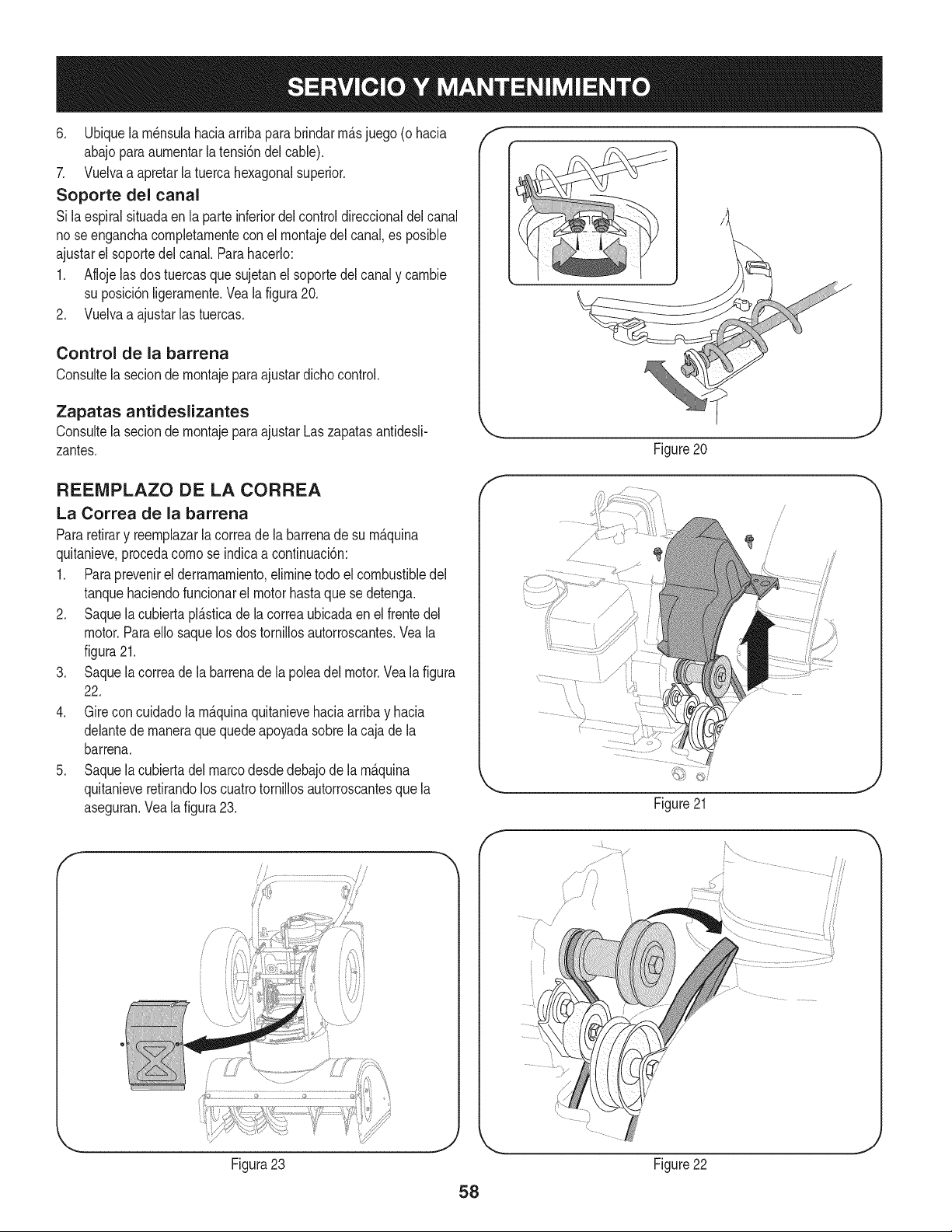
6. Ubiquela rn_nsulahaciaarribaparabrindarrn_.sjuego (o hacia
abajoparaaurnentarla tensi6ndel cable).
7. Vueivaa apretarla tuercahexagonalsuperior.
Soporte del canal
Si laespiralsituadaenla parteinferiordel controldireccionaldel canal
no seenganchacompletarnenteconel rnontajedel canal,es posible
ajustarel soportedelcanal.Parahacerlo:
1. Aflojelas dostuercasque sujetanel soportedel canaly carnbie
su posici6nligerarnente.Vealafigura20.
2. Vuelvaa ajustarlas tuercas.
Control de la barrena
Consultela secionde rnontajeparaajustardichocontrol.
Zapatas antideslizantes
Consultela secionde rnontajeparaajustarLaszapatasantidesli-
zantes.
f
Figure20
J
REENIPLAZO DE LA CORREA
La Correa de la barrena
Pararetirary reernplazarla correade la barrenade su rn_quina
quitanieve,procedacornose indicaacontinuaci6n:
1. Paraprevenirel derrarnarniento,elirninetodo elcombustibledel
tanquehaciendofuncionarel motorhastaquese detenga.
2. Saquela cubiertapl_.sticade la correaubicadaen el frentedeJ
motor.Paraello saquelos dos tornillosautorroscantes.Veala
figura21.
3. Saquela correade la barrenade la poleadel motor.Vealafigura
22.
4. Gire concuidadola rn_quinaquitanievehaciaarribay hacia
delantede rnaneraque quedeapoyadasobrela cajade la
barrena.
5. Saquela cubiertadel marcodesdedebajode la rn_.quina
quitanieveretirandoloscuatrotornillosautorroscantesquela
aseguran.Veala figura23.
f
Figura23
f
\
/
Figure21
Figure22
58
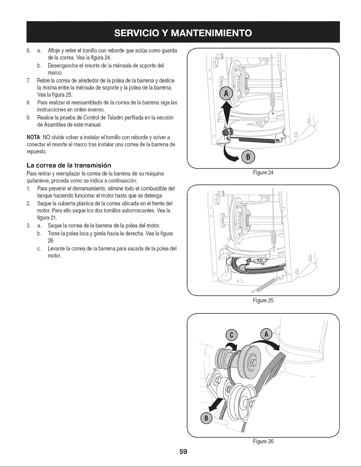
6. a. Aflojey retireel tornillocon rebordequeactOacomoguarda
dela correa.Vealafigura24.
b. Desengancheel resortede la m_nsulade soportedel
marco.
7. Retirela correade alrededorde la poleade la barrenay deslice
la mismaentre la m_nsulade soportey la polea de la barrena.
Vealafigura25.
8. Pararealizarel reensambladode lacorreade labarrenasiga las
instruccionesen orden inverso.
9. Realicela pruebade Controlde Taladroperfiladaen lasecci6n
deAsambleadeestemanual.
NOTA:NOolvidevolvera instalarel tornillocon rebordey volvera
conectarel resorteal marcotras instalaruna correade la barrenade
repuesto.
La correa de la transmisi6n
Pararetirary reemplazarla correade la barrenade su m&quina
quitanieve,procedacomose indicaacontinuaci6n:
1. Paraprevenirel derramamiento,eliminetodoel combustibledel
tanquehaciendofuncionarel motorhastaque sedetenga.
2. Saquela cubiertapl_.sticade la correaubicadaen el frentedel
motor.Paraello saquelosdos tornillosautorroscantes.Veala
figura21.
3. a. Saquela correade la barrenade la poleadelmotor.
b. Tomela polea Iocay girela haciala derecha.Vealafigura
26.
c. Levantela correade la barrenaparasacarlade la polea del
motor.
f
/" }
Figure24
t j
Figure25
59
f
Figure26
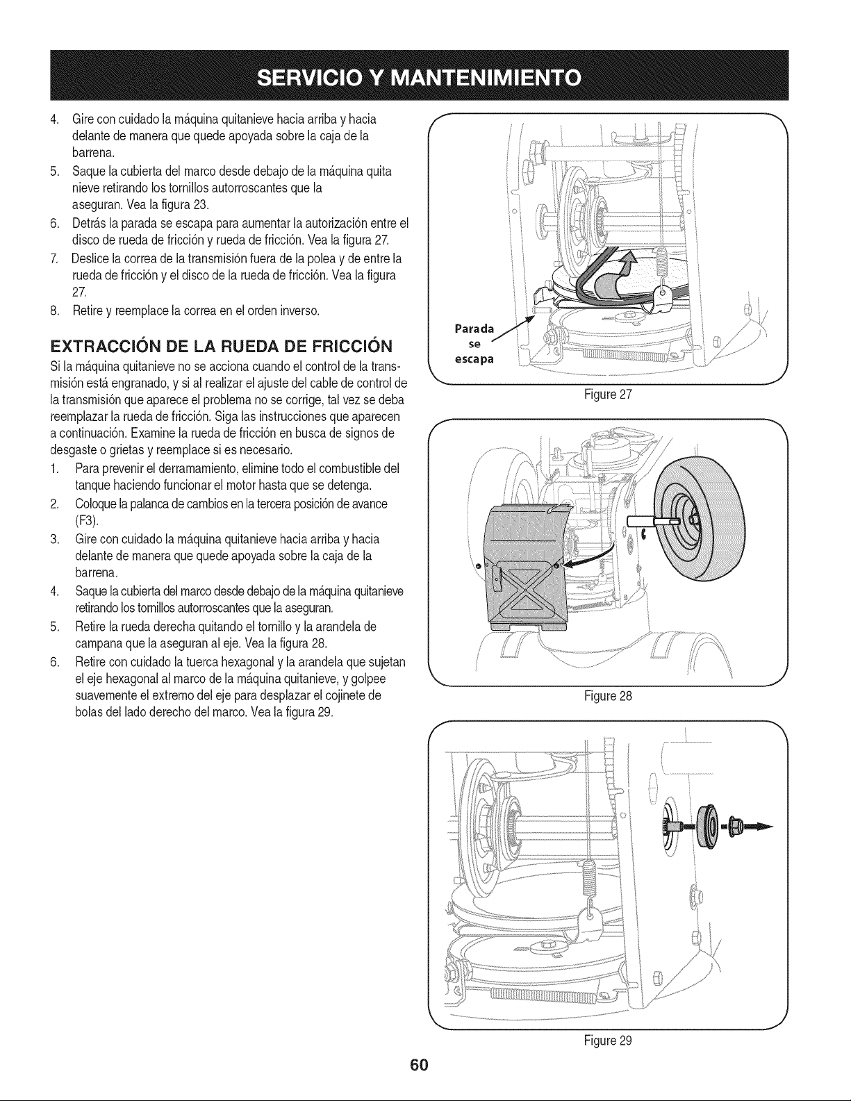
4. Gireconcuidadolarn_.quinaquitanievehaciaarribayhacia
delantedernaneraquequedeapoyadasobrelacajadela
barrena.
5. Saquelacubiertadelmarcodesdedebajodelarn_.quinaquita
nieveretirandolostorniNosautorroscantesquela
aseguran.Vealafigura23.
6. Detr_.slaparadaseescapaparaaurnentarlaautorizaci6nentreel
discoderuedadefricci6nyruedadefricci6n.Vealafigura27.
7. Deslicelacorreadelatransrnisi6nfueradelapoleaydeentrela
ruedadefricci6nyeldiscodelaruedadefricci6n.Vealafigura
27.
8. Retireyreernplacelacorreaenelordeninverso.
EXTRACCI6N DE LA RUEDA DE FRICCI6N
Si larn&quinaquitanievenose accionacuandoel controlde la trans-
rnisi6nest,. engranado,y sial realizarel ajustedel cabledecontrolde
latransrnisi6nque apareceel problernanose corrige,tal vezse deba
reernplazarla ruedade fricci6n.Siga las instruccionesqueaparecen
acontinuaci6n.Examinela ruedade fricci6nen buscade signosde
desgasteo grietas y reernplacesi es necesario.
1. Paraprevenirel derrarnarniento,elirninetodo elcombustibledel
tanquehaciendofuncionarel motorhastaquese detenga.
2. Coloquelapalancade carnbiosen la terceraposici6nde avance
(F3).
3. Gire concuidadola rn_.quinaquitanievehaciaarribay hacia
delantede rnaneraque quedeapoyadasobrela cajade la
barrena.
4. Saquela cubiertadel marcodesdedebajodelarn_.quinaquitanieve
retirandolostornillosautorroscantesquelaaseguran.
5. Retirela ruedaderechaquitandoel tornilloy la arandelade
carnpanaque la aseguranal eje. Veala figura28.
6. Retirecon cuidadola tuercahexagonaly la arandelaque sujetan
eleje hexagonalal marcode la rn_.quinaquitanieve,y golpee
suavernenteel extrernodel eje para desplazarel cojinetede
bolasdel ladoderechodel marco.Vea la figura29.
f
Parada
escapa
Figure27
Figure28
j...................................
J
6O
Figure29
J
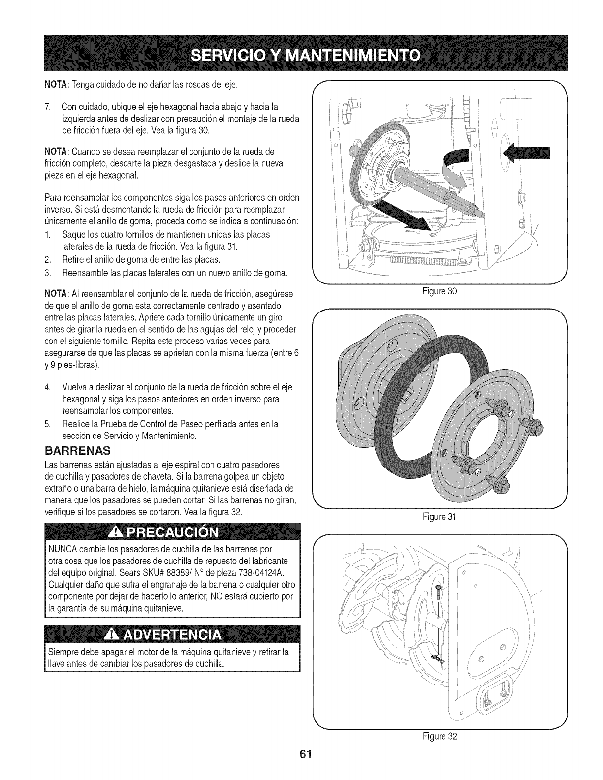
NOTA:TengacuidadodenodaSarlasroscasdeleje. f
7. Concuidado,ubiqueelejehexagonalhaciaabajoyhaciala
izquierdaantesdedeslizarconprecauci6nelrnontajedelarueda
defricci6nfueradeleje.Vealafigura30.
NOTA:Cuandosedeseareernplazarelconjuntodelaruedade
fricci6ncornpleto,descartelapiezadesgastadaydeslicelanueva
piezaenelejehexagonal.
Parareensarnblarloscornponentessigalospasosanterioresenorden
inverso.Siest,.desrnontandolaruedadefricci6nparareernplazar
Onicarnenteelanillodegorna,procedacornoseindicaacontinuaci6n:
1. Saqueloscuatrotornillosdernantienenunidaslasplacas
lateralesdelaruedadefricci6n.Vealafigura31.
2. Retireelanillodegornadeentrelasplacas.
3. Reensarnblelasplacaslateralesconunnuevoanillodegorna.
NOTA:AIreensarnblarelconjuntodelaruedadefricci6n,asegOrese
dequeelanillodegornaestacorrectarnentecentradoyasentado
entrelasplacaslaterales.AprietecadatornilloQnicarnenteungiro
antesdegirarlaruedaenelsentidodelasagujasdelrelojyproceder
conelsiguientetornillo.Repitaesteprocesovariasvecespara
asegurarsedequelasplacasseaprietanconlarnisrnafuerza(entre6
y9pies-libras).
4. Vuelvaadeslizarelconjuntodelaruedadefricci6nsobreeleje
hexagonalysigalospasosanterioresenordeninversopara
reensarnblarloscornponentes.
5. RealicelaPruebadeControldePaseoperfiladaantesenla
secci6ndeServicioyMantenirniento.
BARRENAS
Las barrenasest_.najustadasal eje espiralcon cuatropasadores
decuchillay pasadoresde chaveta.Si la barrenagolpea un objeto
extraSoo unabarrade hielo,la rn_.quinaquitanieveest,.diseSadade
rnaneraquelos pasadoresse puedencortar.Si las barrenasnogiran,
verifiquesi los pasadoresse cortaron.Vea la figura32.
NUNCAcarnbielos pasadoresde cuchillade las barrenaspor
otracosaque lospasadoresde cuchillade repuestodel fabricante
delequipooriginal,SearsSKU#88389/NOde pieza738-04124A.
CualquierdaSoque sufra el engranajedela barrenao cualquierotro
cornponentepordejardehacerloIoanterior,NOestarAcubiertopor
la garantiade su rn_.quinaquitanieve.
Siernpredebeapagarel motorde la rn_.quinaquitanievey retirarla
Ilaveantesde carnbiarlos pasadoresdecuchilla.
Figure30
J
f
Figure31
Figure32
J
61
Sinosevaa utilizael equipodurante30dfasorn_.s,o sies elfinalde la ternporadadenievey ya noexisteposibilidaddeque nieve,es necesario
alrnacenarel equipode rnaneraadecuada.Sigalasinstruccionesdealrnacenarnientoquese indicana continuaci6nparagarantizarelrendirniento
rn_.xirnodelarn_.quinaquitanieveduranternuchosa_os.
PREPARACI6N DEL MOTOR
Losrnotoresquese alrnacenandurantern&sde 30 dfas necesitan
serdrenadosde combustiblepara evitarquese deterioreny se forrne
gornaenel sisternade combustibleoen las piezasprincipalesdel
carburador.Si lagasoNnade su motorse deterioraduranteel alrnace-
narniento,es posibleque deba repararo reernplazarelcarburadory
otroscornponentesdel sisternade combustible.
1. Elirninetodoel combustibledel tanquehaciendofuncionarel
motorhastaquese detenga.
2. Carnbieel aceitedel motor.
3. Extraigala bujfade encendidoy viertaen el cilindroaproxirna-
darnente1 onza(30 rnl)de aceiteparamotorNrnpio.Tire varias
vecesdel arrancadorde retrocesoparadistribuirelaceitey
reinstalela bujfa.
4. Lirnpielos residuosde alrededordel motor,y debajo,alrededor,
y detr_.sdel silenciador.ApNqueunacapa delgadade aceiteen
todaslas _.reasquepuedenNegara oxidarse.
• Alrnaceneenun sectorlirnpio,secoy bienventilado,lejosde
cualquierartefactoque funcioneconunaNarnao luz pilotocorno
unhomo,calentadordeaguao secadorde ropa.Evitecualquier
sectorcon un motorel_ctricoqueproduzcachispaso dondese
utilicenherrarnientasel_ctricas.
Nuncaalrnacenela rn_.quinaquitanieveconcombustibleenel
tanqueenun espaciocerradoo en _.reascon pocaventilaci6n,
dondelosgasesdelcombustiblepuedanalcanzarel fuego,chispas
o unaluz pilotocornola que tienenalgunoshornos,calentadoresde
agua,secadoresde ropa o algQnotto dispositivoa gas.
PREPARACION DE LA iVlAQUINA QUITANIEVE
1. Cuandoalrnacenelarn&quinaquitanieveen un galp6nde
dep6sitornet_.licoo con pocaventilaci6n,tengaespecialcuidado
de realizarleun tratarnientoanti- oxidanteal equipo.Useaceite
ligeroo silic6npararecubrirel equipo,especialrnentelas
cadenas,los resortes,loscojinetesy loscables.
2. Elirninetodo el polvodel exteriordel motory del equipo.
3. Siga las recornendacionesde lubricaci6nen la secci6nde
mantenirnientode este manual.
4. Alrnaceneel equipoen un _.readespejaday seca.
• Si es posible,evite sectoresde alrnacenarnientocon rnucha
hurnedad.
• Mantengael motorniveladoen el alrnac_n.La inclinaci6ndel
motorpuedecausarperdidasde combustibleo aceite.
62

El motornoarranca
El motorfundonade manera
err_.fica
1. La palancade obturaci6nnoest,.en la
posici6nON(encendido)
2. Se ha desconectadoel cablede la bujia
3. La bujfano funcionacorrectamente
4. El tanquede combustibleest,. vado oel
combustiblees viejo
5. El motor no est,. cebado
6. La Ilaveno seencuentraenel encendido
delmotor
7. Cablede extensi6nno conectado(cuando
se usael bot6ndearranqueel_ctrico,en
los modelosequipados).
1. La unidadest,. funcionandoenla posici6n
CHOKE(obturaci6n)
2. EIcombustibleesviejo
3. Aguao suciedaden el sistemadel combus-
tible
4. Es necesarioajustarel carburador
El motorrecalienta 1. El carburadornoest,.ajustadocorrecta-
mente
1. Pongael interruptorenla posici6nCHOKE(obtura-
ci6n).
2. Conecteelcable a labujfa.
3. Limpie.ajuste la distanciadisruptivao cambie.
4. Lleneel tanquecon gasolinalimpiay fresca.
5. Cebeel motortal y como se indicaen la secci6nde
operaci6n.
6. Insertela Ilavetotalmentedentrodelinterruptor.
7. Conecteunextremodel cablede extensi6na la
salidadearranqueel_ctricoy el otroextremoa un
triplede 120-voltios.detierra,tomade CA.
1. Cambiela palancade obturaci6na la posici6nOFF
(apagado).
2. Lleneel tanquecon gasolinalimpiay fresca.
3. Vacieel tanquedelcombustible.Vuelvaa Ilenarlo
concombustiblelimpio.
4. Contactecon sucentro de partes y reparaciones
Sears.
1. Contactecon un centrode partesy servicioSears.
63
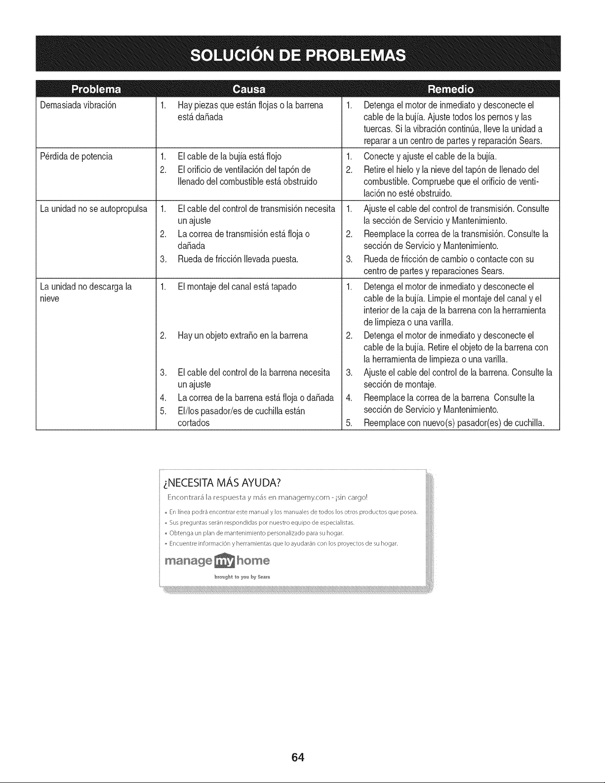
Dernasiadavibraci6n
1. Hay piezasque est_.nflojaso la barrena
estB.dafiada
1. El cablede la bujfaest,.fiojo
2. El orificio de ventilaci6ndel tap6nde
Ilenadodel combustibleest,.obstruido
1. El cabledel controlde transrnisi6nnecesita
unajuste
2. La correade transrnisi6nest,.fiojao
dafiada
3. Ruedadefricci6n Ilevadapuesta.
1. El rnontajedelcanalest,.tapado
2. Hay un objetoextrafioen la barrena
P@didade potencia
Launidadnose autopropulsa
Launidadnodescargala
nieve
Elcabledel controlde la barrenanecesita.
4.
5.
unajuste
Lacorreadela barrenaest,. flojao dafiada
El/lospasador/esde cuchillaest_.n
cortados
1. Detengael motorde inrnediatoy desconecteel
cablede la bujia.Ajustetodos los pernosy las
tuercas.Sila vibraci6ncontinOa.Ilevela unidada
reparara un centrode partesy reparaci6nSears.
1. Conectey ajusteel cablede la bujfa.
2. Retireel hieloy la nievedeltap6nde Ilenadodel
combustible.Cornpruebequeel orificiode venti-
laci6nnoest_obstruido.
1. Ajusteel cabledel controlde transrnisi6n.Consulte
la secci6nde Servicioy Mantenirniento.
2. Reernplacela correade la transrnisi6n.Consultela
secci6nde Servicioy Mantenirniento.
3. Ruedade fricci6nde carnbioo contactecon su
centrode partesy reparacionesSears.
1. Detengael motorde inrnediatoy desconecteel
cablede la bujia. Lirnpieel rnontajedel canaly el
interiorde la caja de la barrenaconla herrarnienta
delirnpiezao unavarilla.
2. Detengael motorde inrnediatoy desconecteel
cablede la bujia. Retireel objetode la barrenacon
la herrarnientade lirnpiezao una varilla.
3. Ajusteel cabledel controlde la barrena.Consultela
secci6nde rnontaje.
4. Reernplacela correade la barrena Consultela
secci6nde Servicioy Mantenirniento.
5. Reernplacecon nuevo(s)pasador(es)de cuchilla.
_NECESITA MAS AYUDA?
iMii/IIi
=En linea podr4 encontrar este marlual y los rT/anualesde todos los otros productos que posea,
,,Sus preguntas ser4r/respondidas pot nuestro equipo de espedalistas,
Obtenga un plan de mantenimiento personalizado para su hogar,
= Encuentre information y herramientas que Io ayudar_n con los proyectos de su hogar.
maHage_Home
64
MTD CONSUMER GROUP, iNC. (MTD), el Bordo de Recursos de Aire de California (CARB)
y la Agencia de Protecci6n Medioambiental de Estados Unidos (U. S. EPA)
Declaraci6n de Garantia del Sistema de Control de Emisiones
(Derechos y obligaciones del propietario seg_n la garantia contra defectos)
LACOBERTURADESISTEMADECONTROLDEEMISIONESAPLICABLEA MOTORESCERTIFICADOSCOMPRADOSENCALIFORNIA
EN2005Y A PARTIRDE ENTONCES,QUESON USADOSEN CALIFORNIA,Y HASTAANO2005DE MODELOCERTIFICADOY MOTORES
POSTERIORESQUESON COMPRADOSY USADOSENOTRAPARTEEN LOSESTADOSUNIDOS.
Californiayen otra parteen la Coberturade Garantiade DefectosdeControlde Emisi6nde los EstadosUnidos
El Bordode Recursosde Aire de California(CARB),la U.S. EPAy MTDsecomplacenen explicarla garantiadel sistemade controldeemisiones
de su motorparaequipotodo terreno,modelo,aSo2005y versionesposteriores.En California,los nuevosmotorespequeSosparaequipotodo
terrenose debendise5ar,fabricary equiparparacumplir conest_.ndaresde antinieblat6xicade estados.Enotraparteen los EstadosUnidos,
el nuevono camino,motoresdeignici6ndechispacertificadosparaelmodelo2005y m_.starde,debeencontrarel juego de est_.ndaressimilar
adelantepor los EstadosUnidos.EPA.MTDdebe garantizarel sistemade controlde emisionesdesu motorpor el periodode tiempoindicadom&s
abajo,siemprey cuandono hayaexistidousoincorrecto,negligencianimantenimientoinadecuadode su motorpequeBoparaequipotodoterreno.
El sistemadecontrolde emisionespuedeincluirpiezascomo,porejemplo,el carburador,sistemadeinyecci6nde combustible,el sistemade
encendido,el catalizador,losdep6sitosde combustible,abastecedecombustiblelineas,gorrasde combustible,v&lvulas,latas,filtros,mangueras
devapor,abrazaderas,conectoresy otroscomponentesrelacionadoscon lasemisiones.
Dondeexistauna condici6ncubiertaporla garantia,MTDreparar&su motor pequeBoparaequipotodoterrenosincostoalgunoincluyendoel
diagn6stico,laspiezasy la manode obra.
COBERTURA DE LA GARANTJA DEL FABRICANTE:
Estesistemade controlde emisionesse garantizaporel t@rminodedos a5os.Si algunapiezade su motorrelacionadacon lasemisioneses
defectuosa,MTD reparar&o sustituir&dichapieza.
RESPONSABJLIDADES DEL PROPIETARIO SEGUN LA GARANTJA:
Comopropietariode un motorpequeSode equipotodoterreno,ustedes responsablede realizarel mantenimientonecesarioquefigura en el
manualdel propietario. MTDle recomiendaque conservetodoslos recibosquecubrenlos serviciosdemantenimientodel motorpeque5opara
equipotodoterreno,noobstanteIo cual MTDno podr&denegarel cumplimientode la garantiaQnicamenteporlafaltade reciboso por su imposi-
bilidaddeasegurarque se realizar_.ntodos los serviciosde mantenimientoprogramado.
Comopropietariodel motorpeque5oparaequipotodo terreno,sinembargo,ustedtambi@ndebesaberque MTDpuededenegarlacoberturadela
garantiasi su motorpeque5opara equipotodoterrenoo unapiezadel mismofallandebidoa usoincorrecto,negligencia,mantenimientoindebido
o a modificacionesno aprobadas.
Ustedes responsablede presentarlacortadoradecespedal centrode distribuci6no de mantenimientode MTDCONSUMERGROUP,INC.tan
prontocomo aparecierael problem& Lasreparacionescubiertaspor lagarantiasedebenIlevaracabo enun lapsorazonableque no excedade
30dias.Si desearealizaralgunaconsultacon respectoa la coberturade lagarantia,debeponerseen contactocon su distribuidorlocalde MTD.
Paracomunicarseconla Linea de Asistenciaal Clientede Distribuidoresde MTD,Ilameal nQmero(877)282-8684.
REQUERJMJENTOS DE GARANTJA SOBRE DEFECTOS PARA MOTORES PEQUENOS DE EQUJPO TODO TERRENO
DE 1995YVERSJONES POSTERJORES:
Estasecci6nse aplicaa motorespeque5osde equipotodo terrenode 1995y versionesposteriores.El periododegarantiacomienzaa partirde la
fechaen que el motoro el equipo seentreganal compradorfinal.
(a) Coberturade la garantiacontraemisionesgenerales
MTDgarantizaal compradorfinaly acada compradorsubsiguienteque el motor:
(1)hasido diseSado,construidoy equipadode maneraquecumplacontodaslas regulacionesvigentesadoptadaspor el Departamentodelos
RecursosdeAire envirtuda suautoridadconferidaen los capitulos1y 2, Parte5, Divisi6n26del C6digode Saludy Seguridad;y
(2)est,. librede defectosen los materialesyen la manode obra que causenla falla de una piezabajo garantiaque seaid@nticaen todos los
aspectosmaterialesa la piezacomo aparecedescriptaen laaplicaci6ndelfabricantedel motorpara certificaci6npor unperiododedos a5os.
_arantia sobre piezasrelacJonadasconemisJonesse interpretar_,de la sJguientemanera:
(1)Cualquierpiezacubierta por garantiaquenoest@programadaparasu reemplazosegQnel mantenimientorequeridoen las instrucciones
escritasdela Subsecci6n(c) debeestargarantizadapor unperiodode garantiadefinidoen la Subsecci6n(a) (2). Si la piezafalladurante
el periododecoberturadela garantia,la mismaser_.reparadao reemplazadapor MTD de acuerdocon la Subsecci6n(4) a continuaci6n.
Cualquierpiezareparadao reemplazadasegQnlagarantiasegarantizarB,porel restodelperiodode garantia.
(2) Cualquierpiezacubiertapor garantiaqueest@programadasolopara inspecci6nregularen las instruccionesescritasde la Subsecci6n
(c) debeestargarantizadaporun periododegarantiadefinidoenla Subsecci6n(a) (2). Unadeclaraci6nen dichasinstruccionespor escrito
alefectode "reparaci6no reemplazosegQnseanecesario"no reducir_,el periodode coberturade la garantia.Cualquierpiezareparadao
reernplazadasegQnlagarantiasegarantizar_,porelrestodelperiododegarantia.
(3) Cualquierpiezagarantizadaqueest_prograrnadaparareernplazosegQnelrnantenirnientorequeridodeconforrnidadconlasinstruc-
clonesescritasdelaSubsecci6n(c)segarantizaporelperiododetiernpoanterioralaprirnerafechadereernplazoprograrnadaparaesa
pieza.Silapiezafallaantesdelprimerreernplazoprogramatic,larnisrnaser_.reparadaoreernplazadaporMTDdeacuerdoconlaSubsecci6n
(4)acontinuaci6n.Cualquierpiezareparadaoreernplazadabajogaranfiasegarantizar_,porelrestodelperiodoanterioralprimerreernplazo
programaticpuntualparaesapieza.
(4)Lareparaci6noelreernplazodecualquierpiezagarantizadadeconforrnidadconlasdisposicionesdelagaranfiaqueaquiseestipulase
deberealizarenuncentrodegaranfiasincostoalgunoparaelpropietario.
(5)SinperjuiciodelasdisposicionesdelaSubsecci6n(4)anterior,losserviciosoreparacionescubiertosporlagaranfiadebensersurnin-
istradosportodosloscentrosdedistribuci6ndeMTDquetenganlafranquiciapararealizarreparacionesyrnantenirnientoalosrnotoresen
cuesti6n.
(6)ElpropietarionodebeafrontarningQncargoparatrabajosdediagn6sticoqueIlevenalaconclusi6ndequeunapiezabajogaranfiapresenta
efectivarnentedefectos,siernpreycuandodichodiagn6sticoseaIlevadoacaboenuncentrocubiertoporlagarantia.
(7)Elfabricantedelmotoresresponsableporda_oscausadosaotroscornponentesdernotoresderivadosdelafallabajogaranfiadecualquier
piezagarantizada.
(8)DurantetodoelperiododegaranfiadelmotordefinidoenlaSubsecci6n(a)(2),MTDrnantendr_,unsurninistrodepiezascubiertaspor
garantiasuficienteparasatisfacerladernandaesperadaparatalespiezas.
(9)Cualquierpiezadereernplazosepodr_,usarparaelcurnplirnientodelrnantenirnientooreparacionesbajogaranfia,ysesurninistrar_,sin
cargoalpropietario.Dichousonoreducir_,lasobligacionesdegarantiadeMTD.
(10)Nosepodr_.nusarpiezasadicionalesnirnodificadasquenoest_nexentasdeacuerdoconelDepartarnentodelosRecursosdelAire(Air
ResourcesBoard).Elusodepiezasadicionalesornodificadasnoexentasser_.causasuficienteparaanularunreclarnobajogaranfiarealizado
deacuerdoconestearticulo.Elfabricantedelmotornotendr_,responsabilidad,enconforrnidadconestearticulo,degarantizarfallasdepiezas
garantizadasquefuerencausadasporelusodeunapiezanoexentaadicionalornodificada.
.(c)MTDincluir_,unacopiade la siguientelistade piezasbajo garantiacontraernisionescon cadanuevomotor,utilizandolas partesde la lista
a_plicablesal motor.
(1)Sisternadernedici6nde combustible
• Sisternade rnejoraparainicioenfrio (cebadosuave)
• Carburadory cornponentesinternos
• Bornbade combustible
• Dep6sitodecombustible
(2) Sisternadeinducci6ndeaire
• Filtrode aire
• Colectordeentrada
(3) Sisternadeencendido
• Bujia(s)
• Sisternadeencendidopor magneto
(4)Sisternadeescape
• Catalizador
• SAI (v_Jvulade Ca_a)
(5) Cornponentesvarios utilizadosen el sisternaanterior
• V_Jvulase interruptoresde vado, ternperatura,posici6nsensiblesal tiernpo
• Conectoresy rnontajes
(6)Controlde Evaporative
• Manguerade CombustiblecertificadaparaARB evaporativeernisi6nde 2006.
• Abrazaderasde Manguerade Combustible
• Gorrade combustibleatada
• Latade carb6n
• Lineasdevapor
GD0C-100174Rev.B
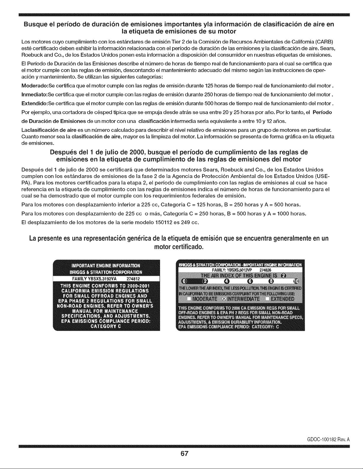
Busque el periodo de duraci6n de emisiones importantes yla informaci6n de clasificaci6n de aire en
la etiqueta de emisiones de su motor
Los motores cuyo cumpiimiento con los estAndares de emisi6n Tier 2 de la Comisi6n de Recursos Ambientales de California (CARB)
est6 certificado deben exhibir la informaci6n relacionada con el perJodo de duraci6n de las emisiones y la clasificaci6n de aire. Sears,
Roebuck and Co., de los Estados Unidos ponen esta informaci6n a disposici6n deJ consumidor en nuestras etiquetas de emisiones.
El Periodo de Duraci6n de las Emisiones describe el nQmero de horas de tiempo real de funcionamiento para el cual se certifica que
el motor cumple con las reglas de emisi6n, descontando el mantenimiento adecuado deJ mismo segQn las instrucciones de oper-
aci6n y mantenimiento. Se utilizan las siguientes categorias:
Moderado:Se certifica que el motor cumpie con las reglas de emisi6n durante 125 horas de tiempo real de funcionamiento deJ motor.
Inmediato:Se certifica que el motor cumple con las reglas de emisi6n durante 250 horas de tiempo real de funcionamiento deJ motor.
Extendido:Se certifica que el motor cumple con las reglas de emisi6n durante 500 horas de tiempo real de funcionamiento deJmotor.
Por ejemplo, una cortadora de c6sped tJpica que se empuja desde atrAs se usa entre 20 y 25 horas por afio. Por Io tanto, el Periodo
de Duraci6n de Emisiones de un motor con una clasificaci6n intermedia seria equivalente a entre 10 y 12 afios.
Laclasificaci6n de aJre es un nQmero calculado para describir eJnivel reiativo de emisiones para un grupo de motores en particular.
Cuanto menor sea Jaclasificaci6n de aire, mayor es JaJimpieza deJ motor. La informaci6n se presenta de forma gr&fica en Jaetiqueta
de emisiones.
Despu_s del 1 de julio de 2000, busque el periodo de cumplimiento de las reglas de
emisiones en la etiqueta de cumplimiento de las reglas de emisiones del motor
Despu_s deJ 1 de julio de 2000 se certificar_, que determinados motores Sears, Roebuck and Co., de los Estados Unidos
cumpien con los estAndares de emisiones de la fase 2 de la Agencia de Protecci6n Ambiental de los Estados Unidos (USE-
PA). Para los motores certificados para la etapa 2, el periodo de cumpiimiento con las reglas de emisiones al cual se hace
referencia en la etiqueta de cumpiimiento con las reglas de emisiones indica el nQmero de horas de funcionamiento para el
cuaJ se ha demostrado que el motor cumpie con los requerimientos federales de emisi6n.
Para los motores con desplazamiento inferior a 225 cc, Categoria C = 125 horas, B = 250 horas y A = 500 horas.
Para los motores con desplazamiento de 225 cc o mAs, Categoria C = 250 horas, B = 500 horas y A = 1000 horas.
El despiazamiento de los motores de la serie modelo 150112 es 249 cc.
La presente es una representaci6n gen_rica de la etiqueta de emisi6n que se encuentra generaimente en un
motor certificado.
GDOC-100182Rev.A
67
Felicitacionespor haberrealizadounaadquisici6ninteligente.El
productoCraftsman@queha adquiridoest_dise_adoy fabricado
parabrindarrnuchosa_osde funcionarnientoconfiable.Perocorno
todoslos productosa vecespuederequerirde reparaciones.Esen
esernornentocuandoel disponerde unAcuerdode protecci6npara
reparacionesle puedeahorrardineroy problernas.
A continuaci6nsedetallanlos puntosincluidosen el Acuerdo:
• Servicio experto prestadopor nuestros10,000especialistasen
reparacionesprofesionales
• Servicio ilirnitadosincargoparalaspiezasy la rnanodeobraen
todaslas reparacionescubiertas
• Reernplazodel productohasta1500d61aressi no es posible
repararel productocubierto
• Descuentode 10%del precionormaldel servicioy de las piezas
relacionadascon el rnisrnoque no est_ncubiertasporel acuerdo;
adern&s,10%del precionormalde laverificaci6nde rnanten-
irnientopreventivo
• Ayudar_pidapottel_fono- IoIlarnarnosResoluci6nR_pida- el
apoyotelef6nicode un Charnuscaal representante.Pienseen
nosotroscornoel manual"de un due_ohablador."
Unavezadquiridoel Acuerdo,puedeprograrnarel serviciocon
tan s61orealizarunaIlarnadatelef6nica.PuedeIlarnarencualquier
mornentodeldia o dela nocheo prograrnarun servicioen linea.
ElAcuerdode Protecci6nde Reparaci6nes unacornprasin riesgo.
Siustedanulaporalgunaraz6nduranteel periodode garantiade
producto,proporcionarernosun reernbolsoIleno.O,un reernbolso
prorrateadoen cualquiermornentodespu_sdelperiodode garantia
de productoexpira,iAdquieraboysu acuerdode protecci6npara
reparaciones!
Seaplican deterrninadaslirnitaciones y exclusiones.Paraobtener
inforrnaci6nadicional y preciosen los Estados UnidosIlarne al
1-800-827-6655.
El*Coverage en Canad_variaen algunosarticulos. Paradetalles
Ilenosla IlarnadaCharnuscaCanad_en 1-800-361-6665.
Servicio de instalaci6nde Sears
Sideseasolicitarla instalaci6nprofesionalde Searsde aparatos
dorn_sticos,dispositivosparaabrirportones,calentadoresde agua
y otrosarficulosdorn_sticosirnportantes,en los EstadosUnidoso
Canad_Ilarneal 1-800-4-MY-HOME®.
68

69

70

71

Your Home
For expert troubleshooting and home solutions advice:
www.managemyhome.com
For repair - in your home - of all major brand appliances,
lawn and garden equipment, or heating and cooling systems,
no matter who made it, no matter who sold it!
For the replacement parts, accessories and
owner's manuals that you need to do-it-yourself.
For Sears professional installation of home appliances
and items like garage door openers and water heaters.
1-800-4-MY-HOME ® (1-800-469-4663)
Call anytime, day or night (U.S.A. and Canada)
www.sears.com www.sears.ca
Our Home
For repair of carry-in items like vacuums, lawn equipment,
and electronics, call anytime for the location of your nearest
Sears Parts & Repair Service Center
1-800-488-1222 (U.S.A.) 1-800-469-4663 (Canada)
www.sears.com www.sears.ca
To purchase a protection agreement on a product serviced by Sears:
1-800-827-6655 (U.S.A.) 1-800-361-6665 (Canada)
Para pedir servicio de reparaci6n
a domicilio, y para ordenar piezas:
1-888-SU-HOGAR ®
(1-888-784-6427)
Au Canada pour service en fran£ais:
1-800-LE-FOYER M°
(1-800-533-6937)
www.sears.ca
® Registered Trademark / TMTrademark / SM Service Mark of Sears Brands, LLC
SM
® Marca Registrada / TMMarca de F&brica / Marca de Servicio de Sears Brands, LLC
MCMarque de commerce / MD Marque depos6e de Sears Brands, LLC © Sears Brands, LLC


