Loading ...
Loading ...
Loading ...
Maintenance(Continued)
e,,,
t_
.m
_E
WARNING
DONOTattempt any maintenance,adjustments or service
with engine and blade running. STOPengineand blade.
Disconnectspark plug wire and secure awayfrom spark
plug. Engineand components are HOT.Avoid serious
burns, allow sufficient time for all components to cool.
Driven Disc Replacement (Continued)
2. Using needlenose pliers, unhook the drive spring (A,
Figure 31) and slide the driven disc assembly off the
hex shaft.
3. Removethe two snap rings (A, Figure 32) which secure
the rubber driven disc (B) to the driven disc assembly.
4. Install a new rubber driven disc onto the driven disc
assembly,and secure with the retaining rings.
5. Reversethe above proceduresfor reassemblyand
installation ofthe driven disc assembly.
Figure31. Removingthe driven disc assembly
Driven Disc Bearing Replacement
IMPORTANT:Thebearing on these machinesis stakedinto
the thrust plate. The bearingwill haveto be driven out with a
mallet and a large punch. A new bearing with four retaining
screws will haveto be purchasedto replaceexisting bearing.
If the driven disc bearing requires replacement,replacethe
bearing as follows:
1. Removethe driven disc assembly. Referto the Section
entitled "Driven Disc Replacement".
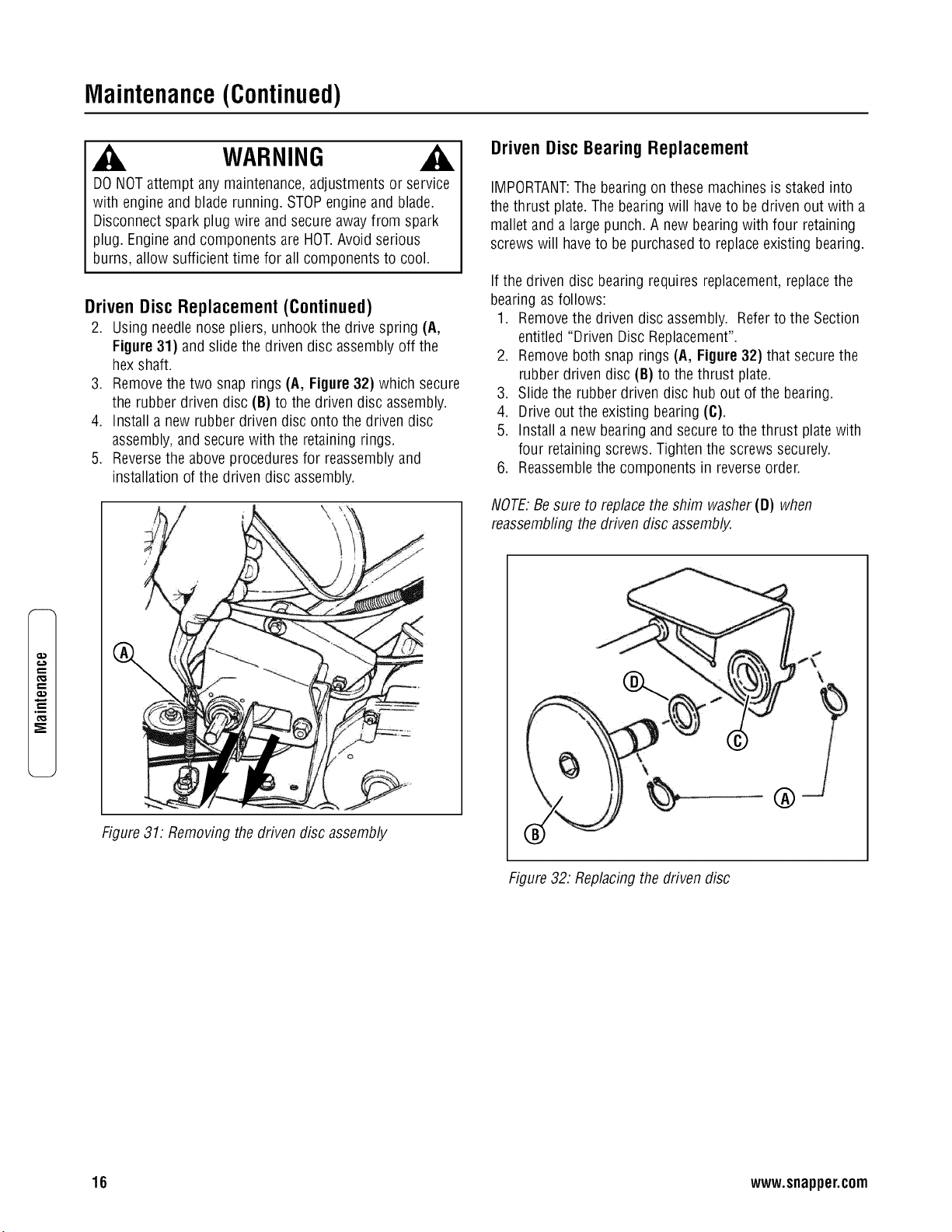
2. Removeboth snap rings (A, Figure 32) that secure the
rubber driven disc (B) to the thrust plate.
3. Slide the rubber driven disc hub out of the bearing.
4. Drive out the existing bearing (C).
5. Install a new bearing and secure to the thrust platewith
four retaining screws. Tighten the screws securely.
6. Reassemblethe components in reverseorder.
NOTE:Besure to replacethe shim washer(D) when
reassembfingthe driven disc assembly.
®
Figure32. Replacing the driven disc
16 www.snapper.com
Loading ...
Loading ...
Loading ...