USER’S MANUAL
Model No. NTEX02117NB.6
Serial No.
Write the serial number in the space
above for reference.
CAUTION
Read all precautions and
instructions in this manual before
using this equipment. Keep this
manual for future reference.
nordictrack.com
To register your product and
activate your warranty today,
go to my.nordictrack.com.
For service at any time, go to
support.nordictrack.com.
Or call 1-800-TO-BE-FIT
(1-800-862-3348)
Mon.–Fri. 6 a.m.–6 p.m. MT
Sat. 8 a.m.–12 p.m. MT
Please do not contact the store.
ACTIVATE YOUR
WARRANTY
CUSTOMER CARE
Serial Number
Decal
2
WARNING DECAL PLACEMENT . . . . . . . . . . . . . . . . . . . . . . . . . . . . . . . . . . . . . . . . . . . . . . . . . . . . . . . . . . . . . . .2
IMPORTANT PRECAUTIONS ..................................................................3
BEFORE YOU BEGIN. . . . . . . . . . . . . . . . . . . . . . . . . . . . . . . . . . . . . . . . . . . . . . . . . . . . . . . . . . . . . . . . . . . . . . . .6
PART IDENTIFICATION CHART. . . . . . . . . . . . . . . . . . . . . . . . . . . . . . . . . . . . . . . . . . . . . . . . . . . . . . . . . . . . . . . .7
ASSEMBLY . . . . . . . . . . . . . . . . . . . . . . . . . . . . . . . . . . . . . . . . . . . . . . . . . . . . . . . . . . . . . . . . . . . . . . . . . . . . . . . .8
HOW TO PLUG IN THE POWER CORD ........................................................16
HOW TO USE THE STUDIO CYCLE ...........................................................17
HOW TO USE THE CONSOLE. . . . . . . . . . . . . . . . . . . . . . . . . . . . . . . . . . . . . . . . . . . . . . . . . . . . . . . . . . . . . . . .19
FCC INFORMATION . . . . . . . . . . . . . . . . . . . . . . . . . . . . . . . . . . . . . . . . . . . . . . . . . . . . . . . . . . . . . . . . . . . . . . . .30
MAINTENANCE AND TROUBLESHOOTING .....................................................31
EXERCISE GUIDELINES ....................................................................34
PART LIST. . . . . . . . . . . . . . . . . . . . . . . . . . . . . . . . . . . . . . . . . . . . . . . . . . . . . . . . . . . . . . . . . . . . . . . . . . . . . . . .36
EXPLODED DRAWING. . . . . . . . . . . . . . . . . . . . . . . . . . . . . . . . . . . . . . . . . . . . . . . . . . . . . . . . . . . . . . . . . . . . . .38
ORDERING REPLACEMENT PARTS. . . . . . . . . . . . . . . . . . . . . . . . . . . . . . . . . . . . . . . . . . . . . . . . . . . Back Cover
LIMITED WARRANTY. . . . . . . . . . . . . . . . . . . . . . . . . . . . . . . . . . . . . . . . . . . . . . . . . . . . . . . . . . . . . . . Back Cover
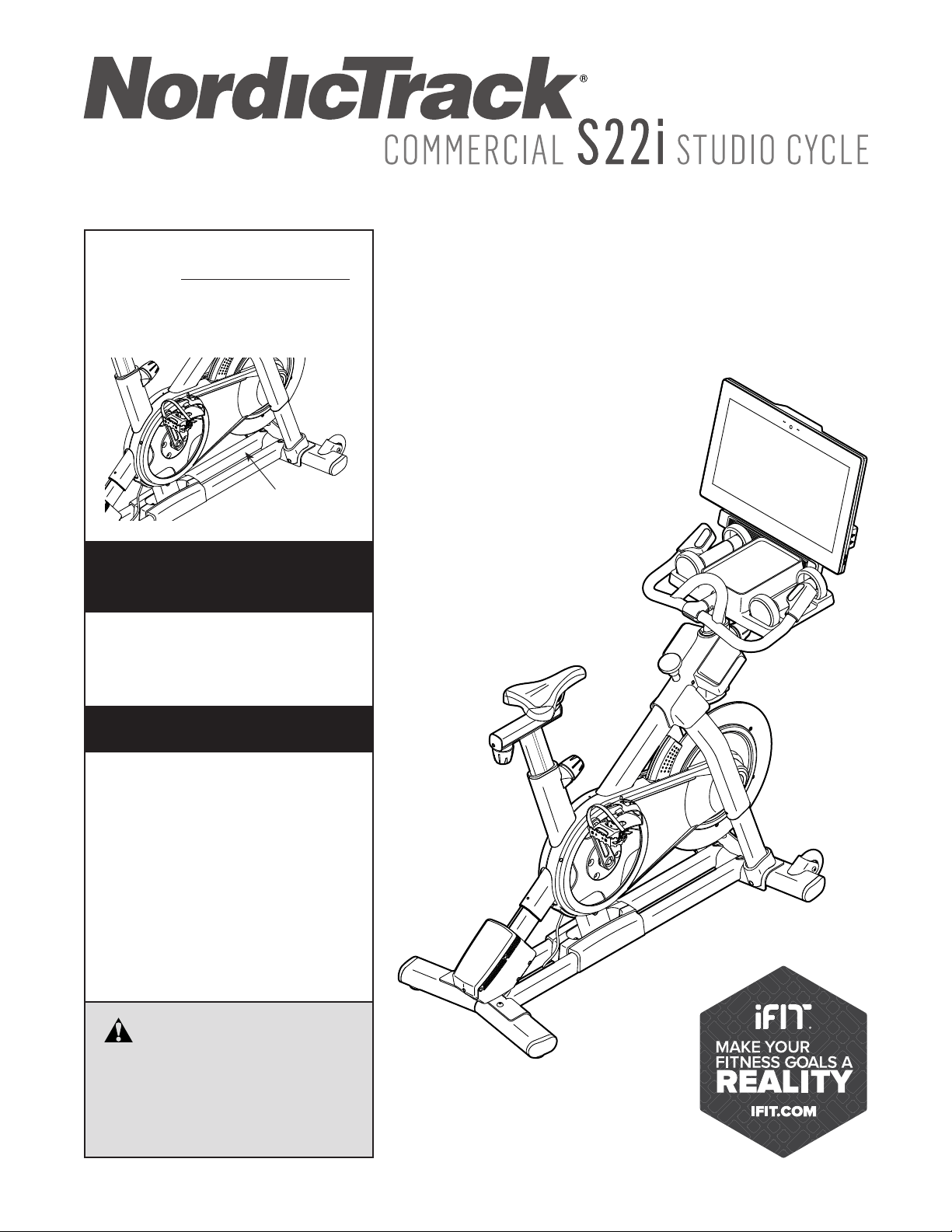
WARNING DECAL PLACEMENT
TABLE OF CONTENTS
This drawing shows the location(s) of the warning
decal(s). If a decal is missing or illegible, see
the front cover of this manual and request a
free replacement decal. Apply the decal in the
location shown. Note: The decal(s) may not be
shown at actual size.
NORDICTRACK and IFIT are registered trademarks of ICON Health & Fitness, Inc. The Bluetooth
®
word mark
and logos are registered trademarks of Bluetooth SIG, Inc. and are used under license. Google Maps is a trade-
mark of Google LLC. Wi-Fi is a registered trademark of Wi-Fi Alliance. WPA and WPA2 are trademarks of Wi-Fi
Alliance.

3
IMPORTANT PRECAUTIONS
WARNING: To reduce the risk of burns, fire, electric shock, or injury to persons, read all
important precautions and instructions in this manual and all warnings on your studio cycle before
using your studio cycle. ICON assumes no responsibility for personal injury or property damage
sustained by or through the use of this product.
1. It is the responsibility of the owner to ensure
that all users of the studio cycle are ade-
quately informed of all precautions.
2. Before beginning any exercise program,
consult your physician. This is especially
important for persons over age 35 or persons
with pre-existing health problems.
3. The studio cycle is not intended for use by
persons with reduced physical, sensory, or
mental capabilities or lack of experience and
knowledge, unless they are given supervi-
sion or instruction about use of the studio
cycle by someone responsible for their
safety.
4. Use the studio cycle only as described in this
manual.
5. The studio cycle is intended for home use
only. Do not use the studio cycle in a com-
mercial, rental, or institutional setting.
6. Keep the studio cycle indoors, away from
moisture and dust. Do not put the studio
cycle in a garage or covered patio, or near
water.
7. Place the studio cycle on a level surface with
at least 2 ft. (0.6 m) of clearance around the
studio cycle. To protect the floor or carpet
from damage, place a mat under the studio
cycle.
8. Inspect and properly tighten all parts each
time the studio cycle is used. Replace any
worn parts immediately.
9. Keep children under age 16 and pets away
from the studio cycle at all times.
10. When connecting the power cord (see
page 16), plug the power cord into a
grounded circuit.
11. Do not modify the power cord or use an
adapter to connect the power cord to an
improper receptacle. Keep the power cord
away from heated surfaces. Do not use an
extension cord.
12. Do not operate the studio cycle if the power
cord or plug is damaged, or if the studio
cycle is not working properly.
13. DANGER: Always unplug the power
cord and press the power switch to the off
position when the studio cycle is not in
use and before cleaning the studio cycle.
Servicing other than the procedures in this
manual should be performed by an autho-
rized service representative only.
14. Wear appropriate clothes while exercising;
do not wear loose clothes that could become
caught on the studio cycle. Always wear ath-
letic shoes for foot protection.

4
15. The studio cycle should not be used by
persons weighing more than 350 lbs.
(159 kg).
16. Be careful when mounting and dismounting
the studio cycle.
17. Always keep your back straight while using
the studio cycle; do not arch your back.
18. The studio cycle does not have a freewheel;
the pedals will continue to move until the
flywheel stops. Reduce your pedaling speed
in a controlled way.
19. To stop the flywheel quickly, press the brake
knob downward.
20. Over exercising may result in serious injury
or death. If you feel faint, if you become short
of breath, or if you experience pain while
exercising, stop immediately and cool down.
SAVE THESE INSTRUCTIONS
5
STANDARD SERVICE PLANS
6
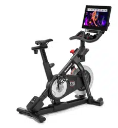
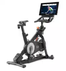
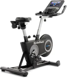
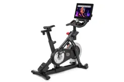
Congratulations for selecting the revolutionary
NORDICTRACK
®
COMMERCIAL S22I STUDIO
CYCLE. The COMMERCIAL S22I STUDIO CYCLE is
unlike any ordinary exercise bike.
With full adjustability, an interactive wireless touch-
screen console, an incline system that simulates
real-world terrain, and an array of other features, the
COMMERCIAL S22I STUDIO CYCLE provides an
immersive in-home studio cycling experience.
For your benefit, read this manual carefully before
you use the studio cycle. If you have questions after
reading this manual, please see the front cover of this
manual. To help us assist you, note the product model
number and serial number before contacting us. The
model number and the location of the serial number
decal are shown on the front cover of this manual.
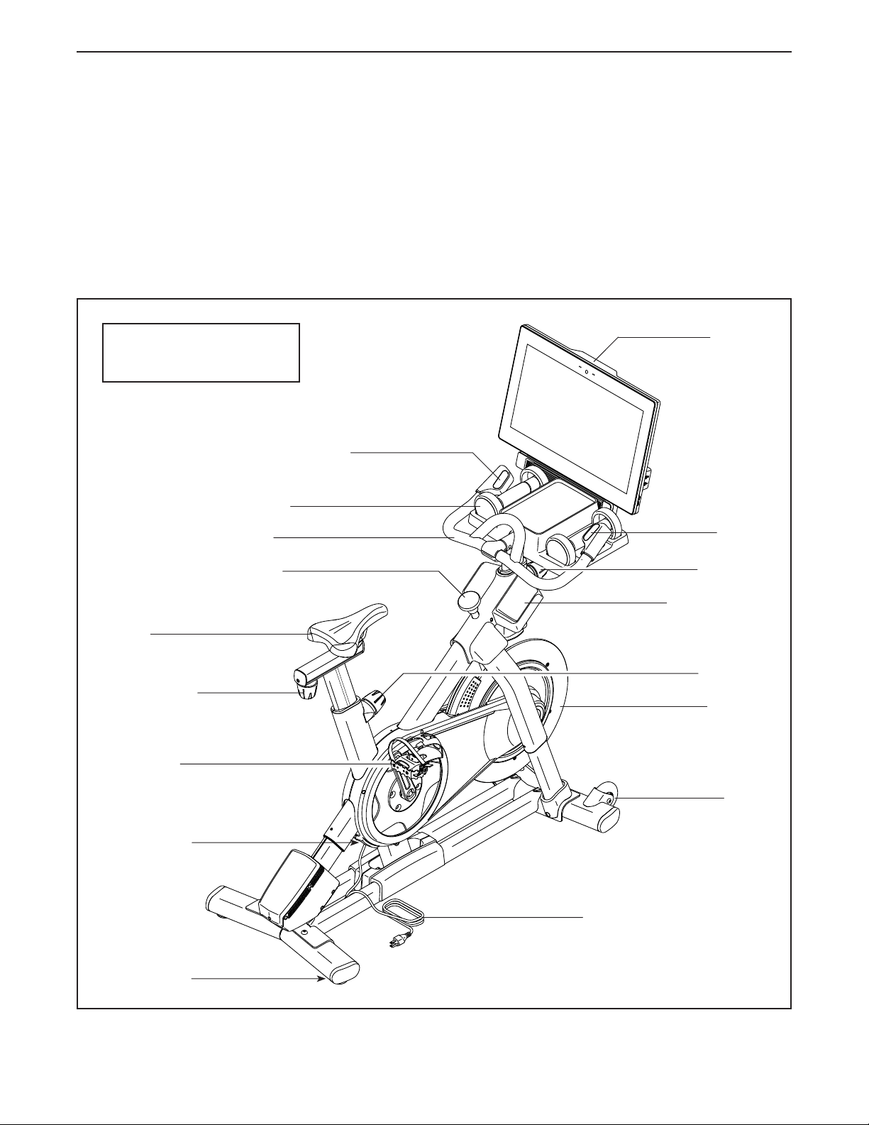
Before reading further, please familiarize yourself with
the parts that are labeled in the drawing below.
Carriage Knob
Post Knob
Post Knob
Pedal/Strap
Flywheel
BEFORE YOU BEGIN
Wheel
Power Cord
Leveling Foot
Power Switch
Length: 2 ft. 11 in. (89 cm)
Width: 1 ft. 10 in. (56 cm)
Saddle
Console
Accessory Tray
Hand Weight
Handlebar
Incline/Decline Control
Resistance
Control
Brake Knob
7
PART IDENTIFICATION CHART
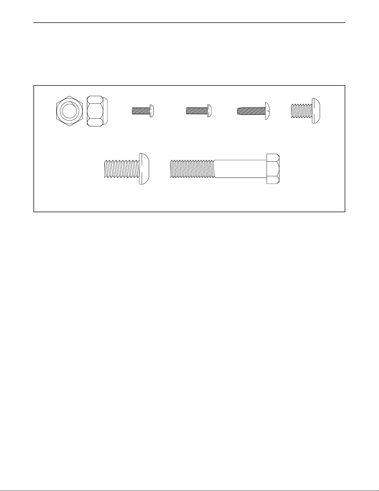
Use the drawings below to identify the small parts needed for assembly. The number in parentheses below each
drawing is the key number of the part, from the PART LIST near the end of this manual. The number following the
key number is the quantity needed for assembly. Note: If a part is not in the hardware kit, check to see if it
has been preassembled. Extra parts may be included.
M10 x 20mm
Screw (105)–12
M10 x 55mm Bolt (94)–1
M4 x 12mm
Machine
Screw (102)–4
M8 x 12mm
Patch Screw
(93)–4
M4 x 10mm
Screw (103)–2
#8 x 5/8"
Screw (17)–4
M10 Locknut
(135)–1
8
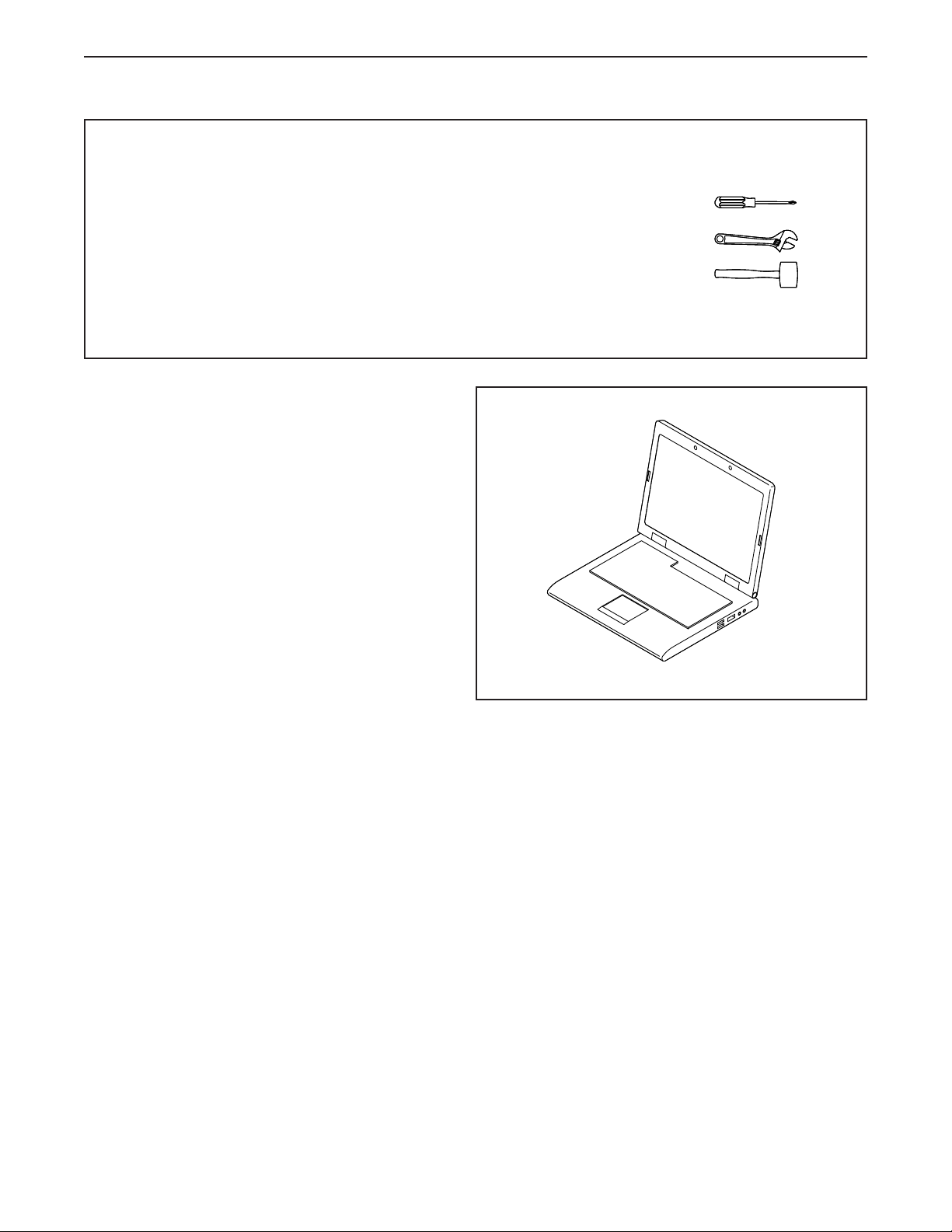
• Assembly requires two persons.
• Place all parts in a cleared area and remove the
packing materials. Do not dispose of the packing
materials until you complete all assembly steps.
• To identify small parts, see page 7.
• To avoid damaging parts, do not use power tools.
• In addition to the included tool(s), assembly
requires the following tool(s):
one Phillips screwdriver
one adjustable wrench
one rubber mallet
Assembly may be easier if you have a set of
wrenches.
ASSEMBLY
1
1. Go to my.nordictrack.com on your computer
and register your product.
• documents your ownership
• activates your warranty
• ensures priority customer support if assistance
is ever needed
Note: If you do not have internet access, call
Customer Care (see the front cover of this
manual) and register your product.
9
2
3
105
105
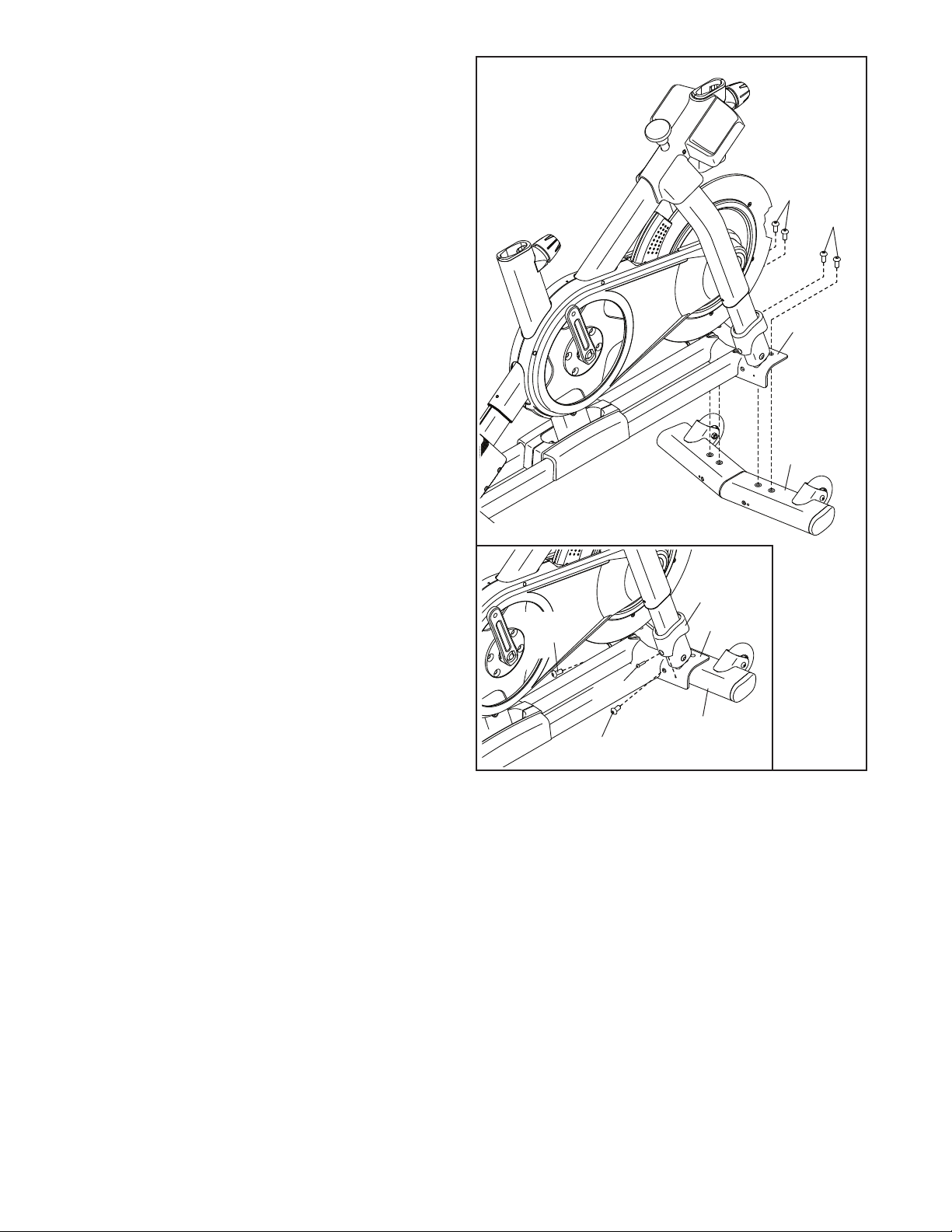
2. Attach the Front Stabilizer (3) to the Base (2)
with four M10 x 20mm Screws (105); do not
fully tighten the Screws yet.
See the inset drawing. Finish attaching
the Front Stabilizer (3) with two additional
M10 x 20mm Screws (105).
Then, fully tighten all six M10 x 20mm
Screws (105).
See the inset drawing. Press the right Leg
Cover (64) downward and attach it to the Base
(2) with an M4 x 10mm Screw (103). Then,
attach the left Leg Cover (not shown) in the
same way.
105
103
64
2
105
2
3
10
3
4
105
105
3. Attach the Rear Stabilizer (4) to the Base (2)
with four M10 x 20mm Screws (105); do not
fully tighten the Screws yet.
See the inset drawing. Finish attaching
the Rear Stabilizer (4) with two additional
M10 x 20mm Screws (105).
Then, fully tighten all six M10 x 20mm
Screws (105).
2
105
4
105
4
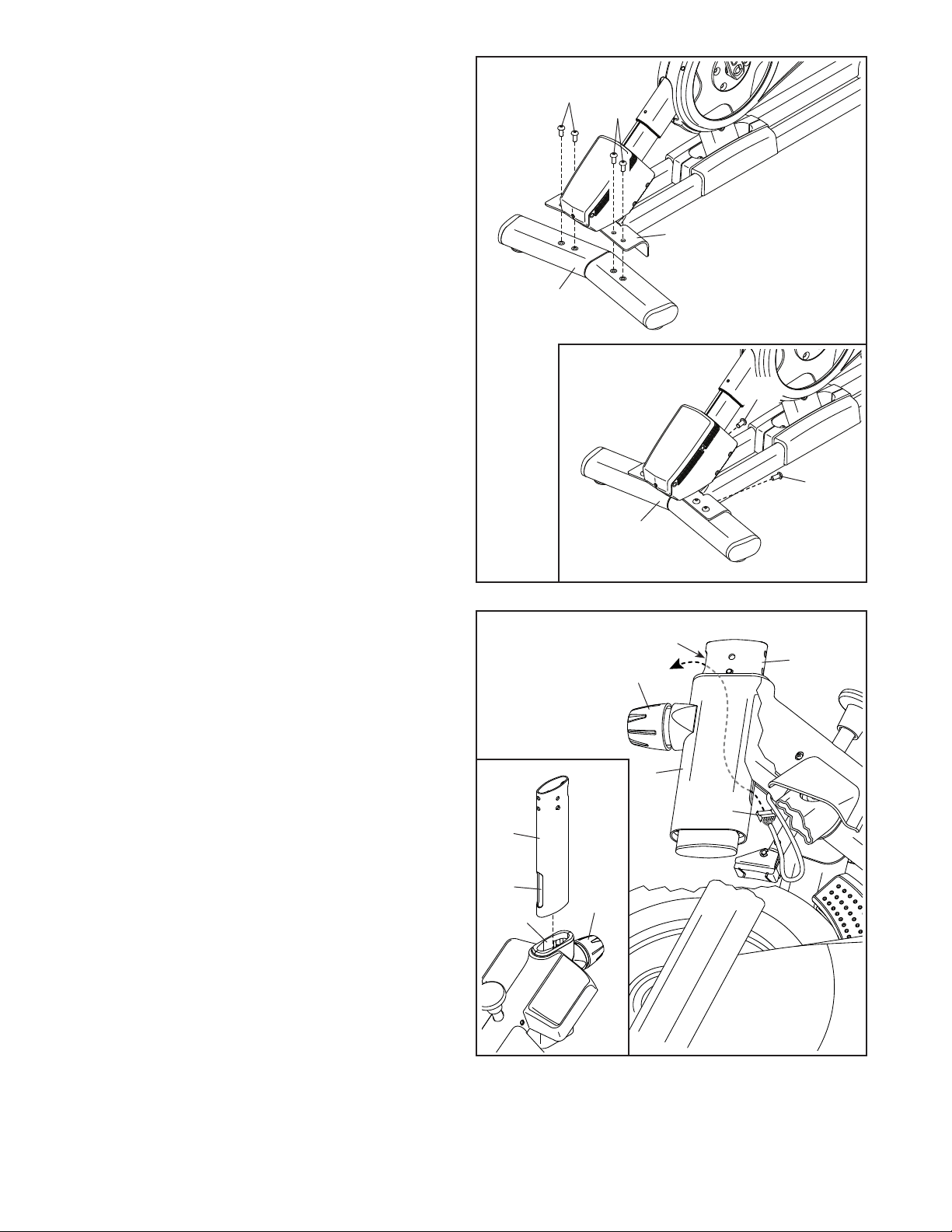
4. See the inset drawing. Orient the Handlebar
Post (7) so that the lower slot (A) is on the side
shown.
Next, loosen the indicated Post Knob (100) and
insert the Handlebar Post (7) into the Frame
(1) until the lower end of the Handlebar Post is
below the Frame. Then, tighten the Post Knob.
Then, insert the end of the Lower Wire (122) into
the Frame (1) and the Handlebar Post (7) and
pull it out of the upper slot (B) in the Handlebar
Post as shown by the dashed line at the right.
100
100
122
7
A
B
1
7
1
11
5
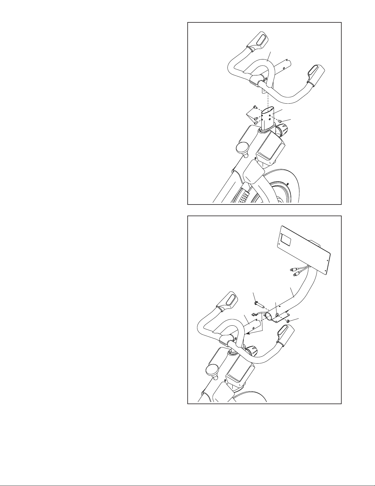
6. Tip: Avoid pinching the wires (C). Slide the
Console Support (8) onto the Handlebar (97).
Attach the Console Support (8) with an
M10 x 55mm Bolt (94) and an M10 Locknut
(135); make sure that the Locknut is in the
hexagonal hole (D). Do not fully tighten the
Bolt yet.
Avoid pinching
the wires (C)
6
D
C
94
8
97
135
5. Insert the Handlebar (97) into the Handlebar
Post (7). Attach the Handlebar with four
M8 x 12mm Patch Screws (93); start all the
Patch Screws, and then tighten them.
97
7
93
93
12
7. Look under the Console Support (8) and identify
the Upper/Yellow Wire (123), which has a larger
connector than the Extension/Red Wire (124).
Connect the Upper/Yellow Wire (123) to the
Lower Wire (122) extending from the Handlebar
Post (7). Then, insert the connectors on both
Wires into the Handlebar Post.
Next, connect the Extension/Red Wire (124)
to the Control Wire (125) extending from the
Handlebar (97). Then, insert the connectors on
both Wires into the Handlebar.
8
7
97
122
125
124
7
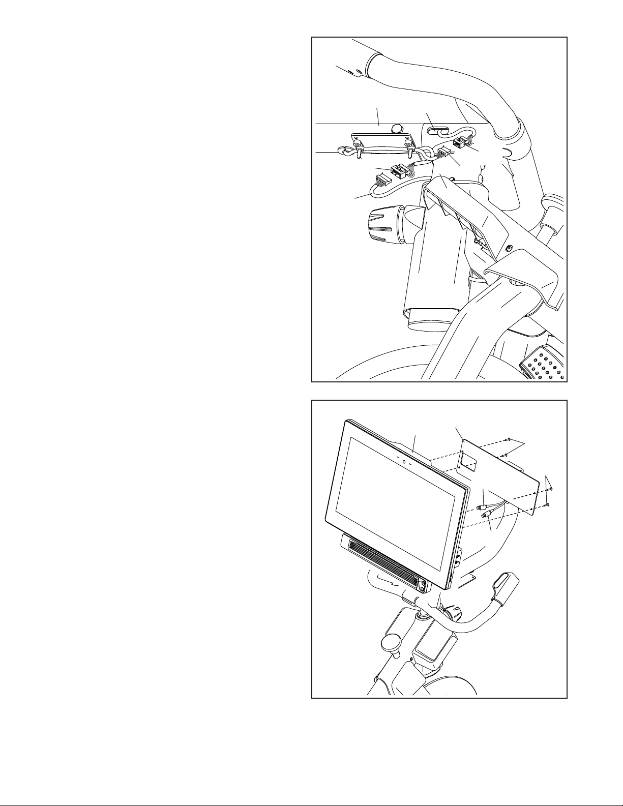
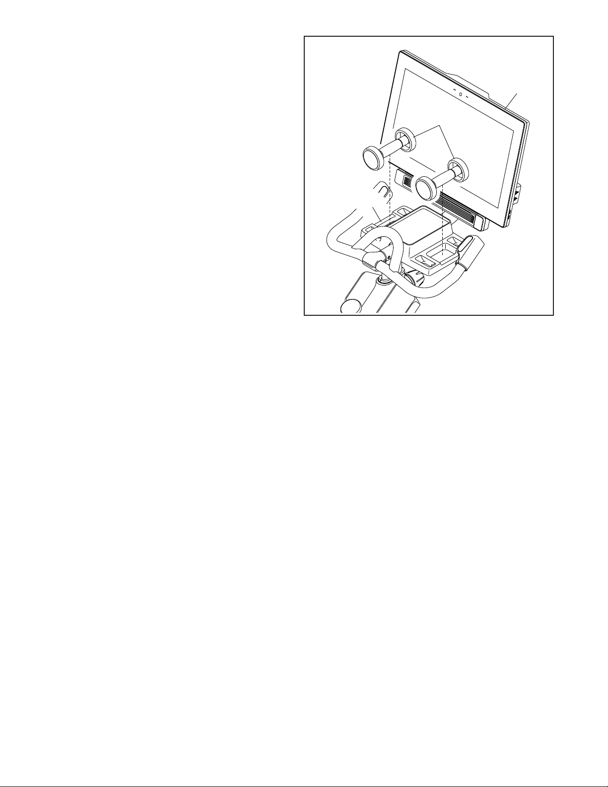
8. Have a second person hold the Console (10)
near the Console Bracket (11).
Plug the Upper/Yellow Wire (123) and the
Extension/Red Wire (124) into the receptacles
on the back of the Console (10); make sure
to plug the Wire marked with red into the
receptacle marked with red, and plug the
Wire marked with yellow into the receptacle
marked with yellow.
Tip: Avoid pinching the wires. If necessary,
tilt the Console Bracket (11) upward to make
this step easier. Attach the Console (10) to the
Console Bracket with four M4 x 12mm Machine
Screws (102); start all the Machine Screws,
and then tighten them.
Avoid pinching
the wires
8
102
11
10
102
123
124
123
13
10
17
C
94
9
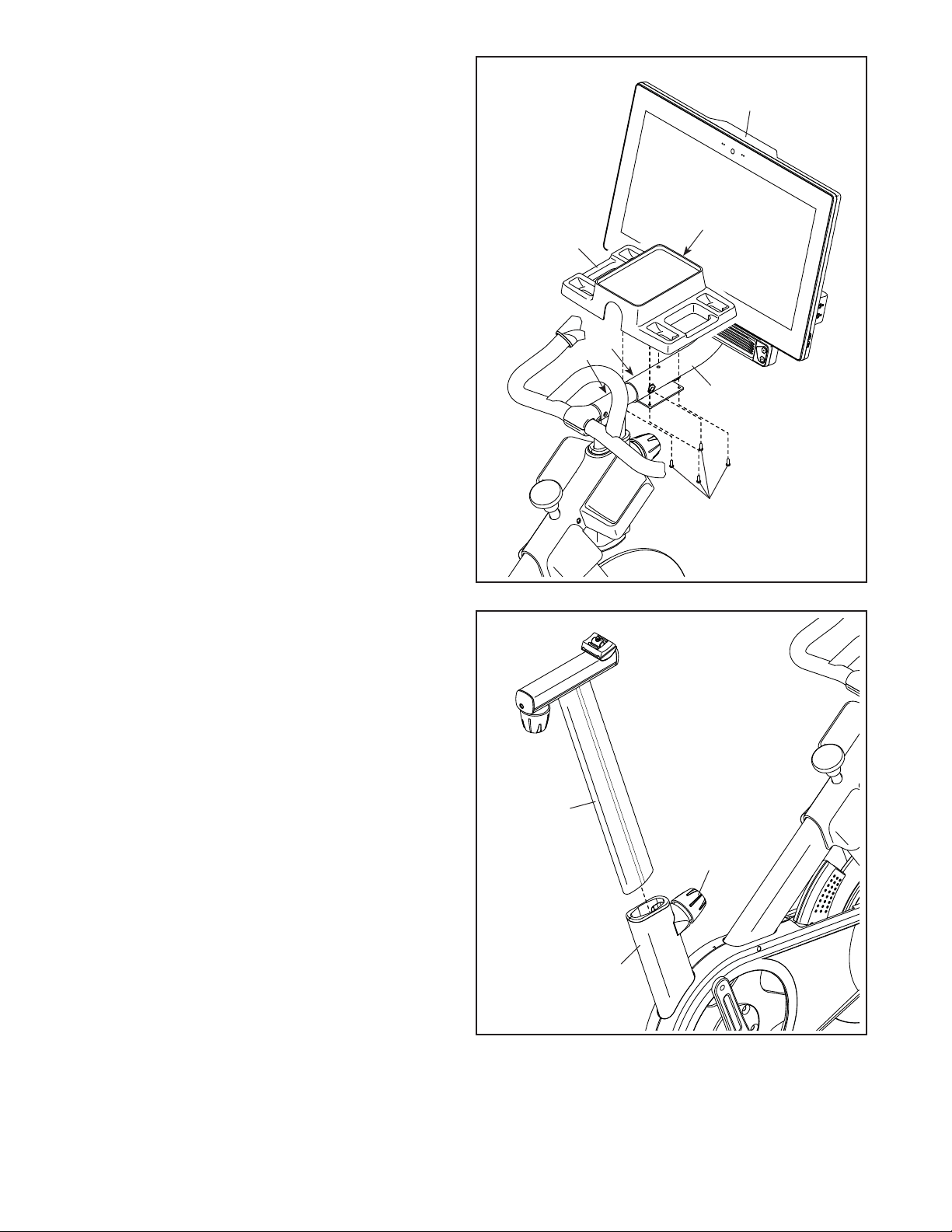
9. IMPORTANT: Have a second person move the
Console (10) from side to side, if necessary,
so that it is level. While the second person
holds the Console still, firmly tighten the
M10 x 55mm Bolt (94).
Next, orient the Hand Weight Tray (38) so that
the largest opening (E) is facing forward.
Tip: Avoid pinching the wires (C). Attach the
Hand Weight Tray (38) to the Console Support
(8) with four #8 x 5/8" Screws (17); start all the
Screws, and then tighten them.
Avoid
pinching
the wires
(C)
8
38
E
13
1
100
10
10. Orient the Saddle Post (13) as shown.
Loosen the indicated Post Knob (100). Next,
insert the Saddle Post (13) into the Frame (1),
and slide the Saddle Post to the desired height.
Then, tighten the Post Knob.
14
41
54
53
52
F
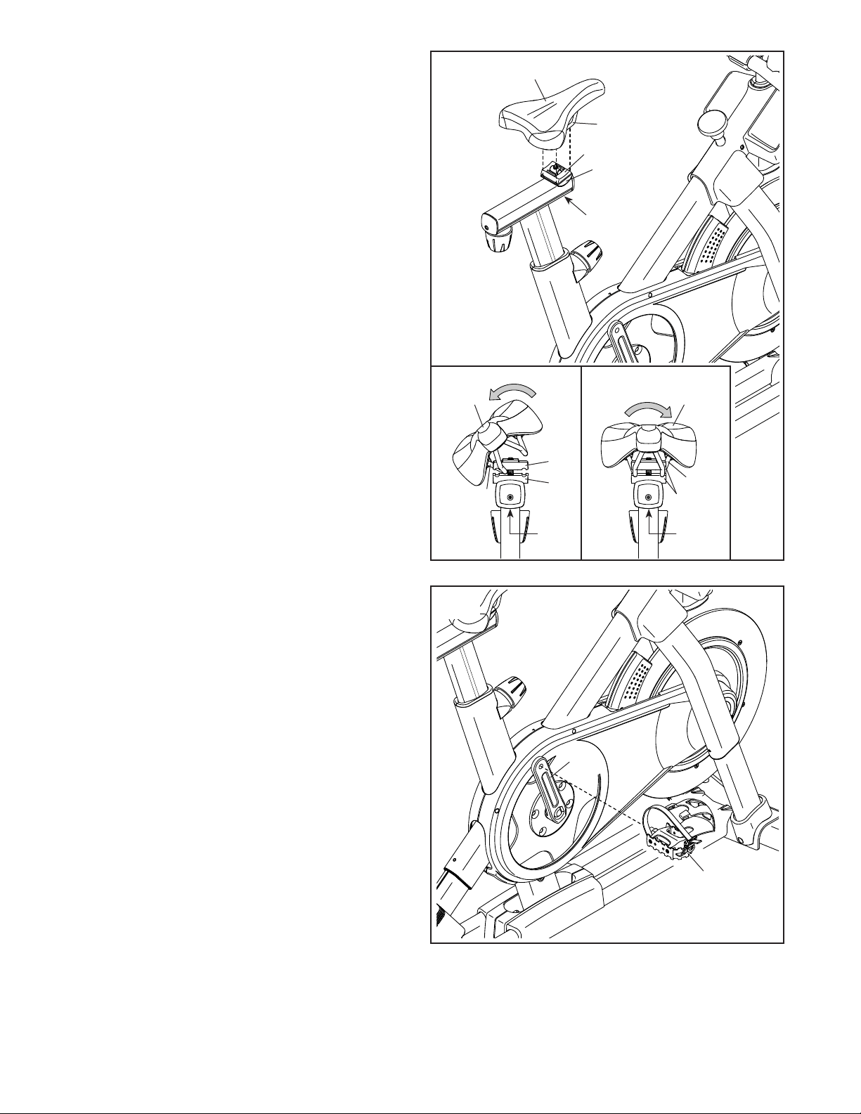
11. Note: You can attach your own saddle if
desired.
See inset drawing a. Tip the Saddle (54) to
one side and slide one of the rails (F) as far as
possible between the Lower Saddle Clamp (52)
and the Upper Saddle Clamp (53). If necessary,
further loosen the M8 Saddle Screw (41).
See inset drawing b. Tip the Saddle (54)
downward as shown and slide the other rail (F)
between the Saddle Clamps (52, 53). Make
sure that both rails are in the grooves in the
Saddle Clamps and that the Saddle is straight
and level. Then, firmly tighten the Saddle
Screw (41).
11
54
54
a
b
53
52
52, 53
F
F
41
41
56
12. Note: You can attach your own pedals if
desired.
Identify the right Pedal (56). Using an adjustable
wrench or the included tool, firmly tighten the
right Pedal clockwise into the Right Crank
Arm (19).
Firmly tighten the left Pedal (not shown)
counterclockwise into the Left Crank Arm
(not shown). IMPORTANT: You must turn the
left Pedal counterclockwise to attach it.
12
19
15
14
10
13. Set the two Hand Weights (14) in the Hand
Weight Tray (38).
IMPORTANT: Make sure not to hit the
Console (10) with the Hand Weights (14)
when you set the Hand Weights in the Hand
Weight Tray (38) after each use.
13
14. After the studio cycle is assembled, inspect it to make sure that it is assembled correctly and that it
functions properly. Make sure that all parts are properly tightened before you use the studio cycle.
Extra parts may be included. Place a mat beneath the studio cycle to protect the floor.
38
16
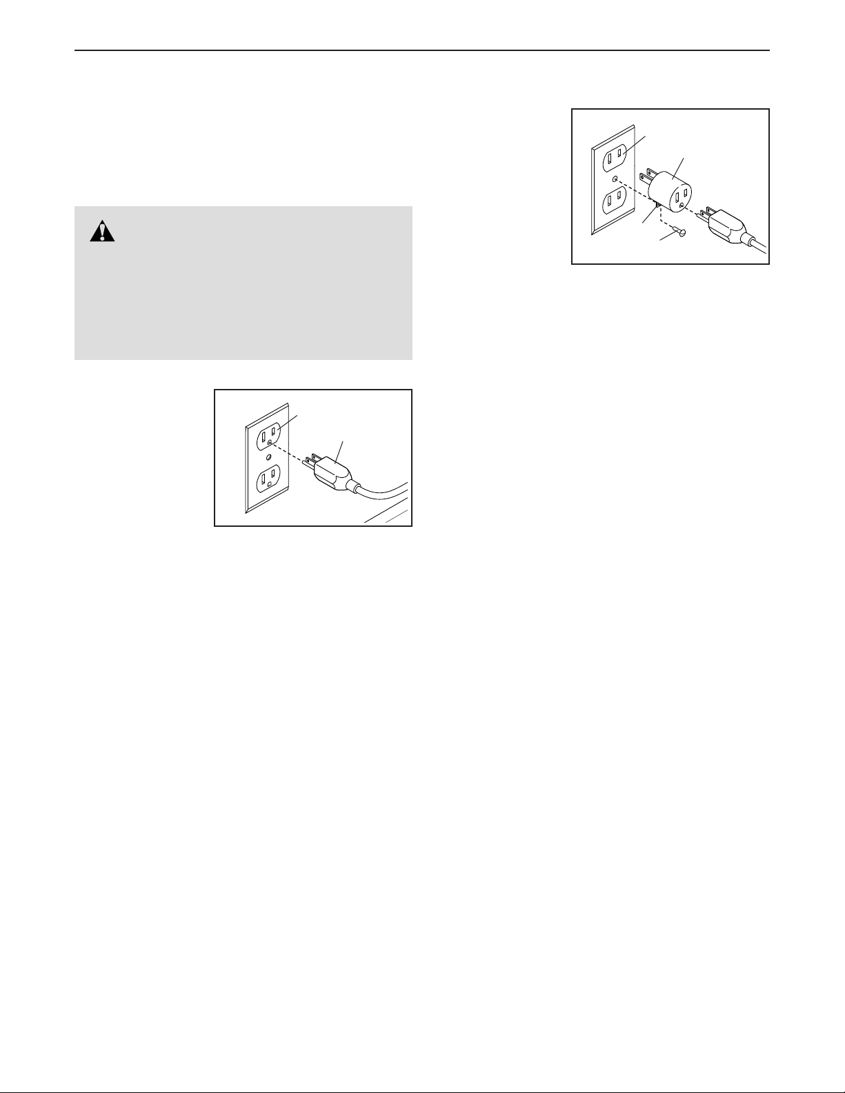
HOW TO PLUG IN THE POWER CORD
This product must be grounded. If it should mal-
function or break down, grounding provides a path of
least resistance for electric current to reduce the risk
of electric shock. The power cord has a plug with a
grounding pin.
Plug the power
cord (A) into
an appropriate
outlet (B) that is
properly installed
and grounded in
accordance with
all local codes and
ordinances. The
outlet must be
on a nominal 120-volt circuit.
A temporary
adapter (C) may
be used to con-
nect the power
cord to a 2-pole
receptacle (D)
as shown at the
right if a properly
grounded outlet is
not available.
The lug (E) or wire extending from the adapter must
be connected with a metal screw (F) to a permanent
ground such as a properly grounded outlet box cover.
Some 2-pole receptacle outlet box covers are not
grounded. Before using an adapter, contact a
qualied electrician to determine whether the out-
let box cover is grounded before using an adapter.
The temporary adapter should be used only until
a properly grounded outlet can be installed by a
qualied electrician.
B
A
DANGER: Improper connection of
the power cord increases the risk of electric
shock. Do not modify the plug—if it will not fit
an outlet, have a proper outlet installed by a
qualified electrician. If you are unsure whether
the product is properly grounded, contact a
qualified electrician.
D
C
E
F
17
FEATURES OF THE STUDIO CYCLE
Measuring Watts
Each studio cycle is calibrated to measure your power
output and to allow you to monitor your watts and
RPMs directly on the console.
By monitoring your watts and RPMs, you can see
how hard you are training and make sure that you are
challenging yourself and improving.
The Incline System
The studio cycle can incline and decline to realistically
simulate outdoor terrain. When you use or create map
workouts of training routes with iFit
®
(see the console
instructions beginning on page 19 for more informa-
tion), the studio cycle will automatically incline and
decline to match the real-world terrain.
Interactive Wireless Touchscreen Console
The wireless touchscreen console works with iFit to
provide an interactive and immersive in-home studio
experience that allows you to participate virtually in
group studio classes led by personal trainers and to
experience workouts around the world.
HOW TO ADJUST THE GEOMETRY OF THE
STUDIO CYCLE
The studio cycle can be adjusted to match the geom-
etry of your road bike to promote correct form and to
ensure proper training of the muscles. Make adjust-
ments in small increments, and then pedal the
studio cycle to test the adjustments.
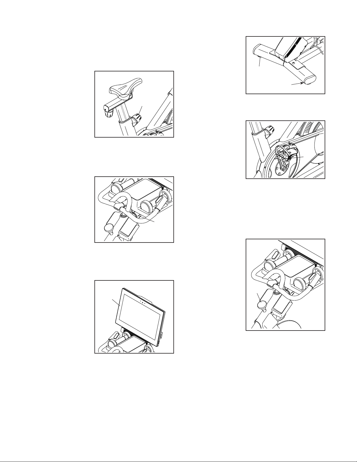
How to Adjust the Angle of the Saddle
You can adjust the angle of the saddle to the posi-
tion that is most comfortable. You can also adjust the
saddle forward or backward for increased comfort or to
adjust the distance to the handlebar.
To adjust the sad-
dle, first loosen the
saddle screw (A) in
the carriage a few
turns. Next, tilt the
saddle upward or
downward or slide
the saddle forward
or backward to the
desired position.
Then, retighten the saddle screw.
Note: You can remove the saddle and attach your
own saddle to the studio cycle if desired.
How to Adjust the Saddle Carriage
To adjust the posi-
tion of the carriage,
loosen the carriage
knob (B), move the
saddle carriage for-
ward or backward to
the desired posi-
tion, and then firmly
tighten the carriage
knob.
A
B
HOW TO USE THE STUDIO CYCLE
18
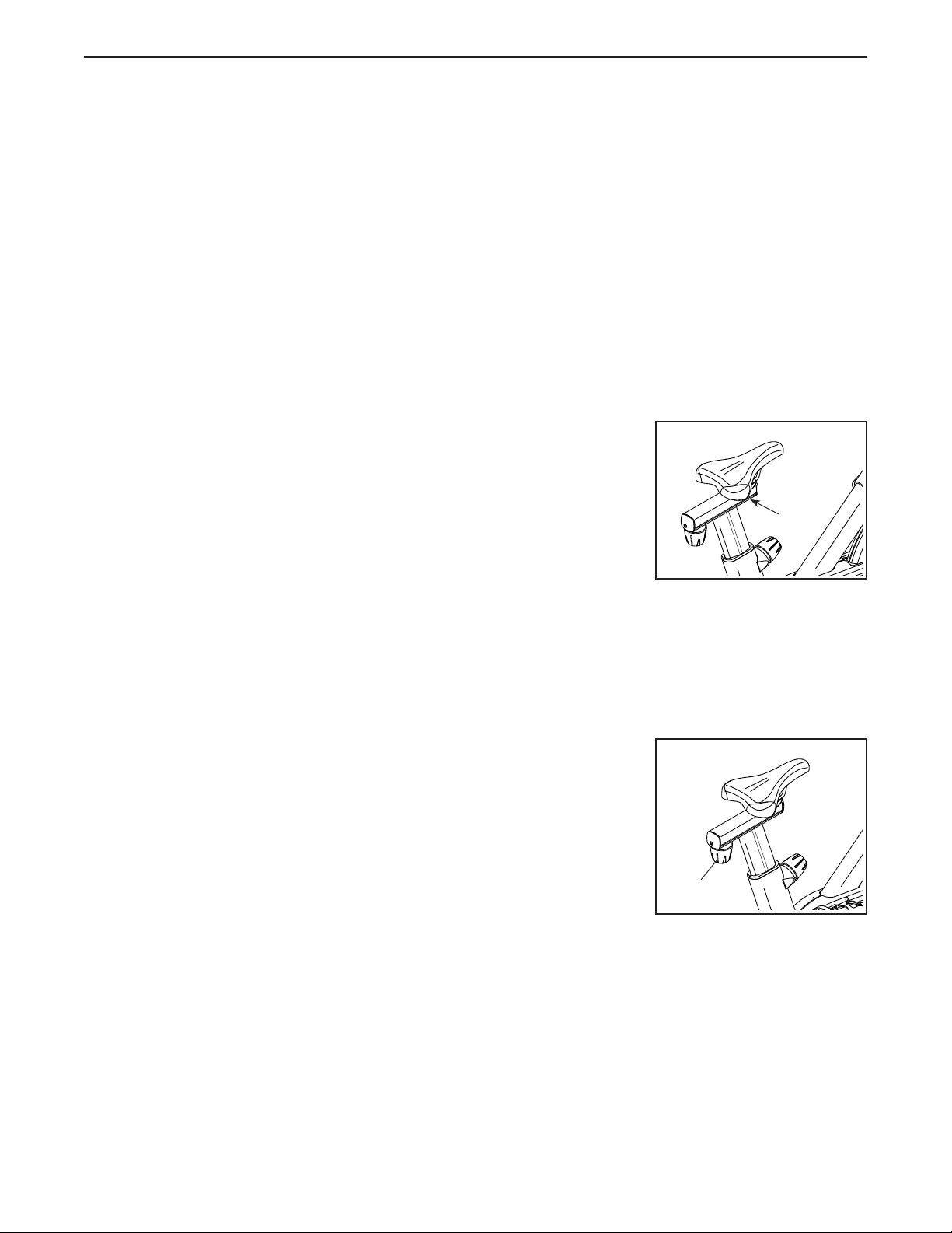
How to Adjust the Saddle Post
For effective training, the saddle should be at the
proper height. As you pedal, there should be a slight
bend in your knees when the pedals are in the lowest
position.
To adjust the saddle
post, loosen the
post knob (C),
move the saddle
post upward or
downward, and
then firmly tighten
the post knob.
IMPORTANT: Do
not raise the sad-
dle post beyond
the “MAX” mark on the saddle post.
How to Adjust the Handlebar Post
To adjust the han-
dlebar post, loosen
the post knob (D),
move the handle-
bar post upward
or downward, and
then firmly tighten
the post knob.
IMPORTANT:
Do not raise the
handlebar post
beyond the “MAX” mark on the handlebar post.
How to Adjust the Position of the Console
The console (E) can
be adjusted upward,
downward, or to
the side. To adjust
the position of the
console, simply
hold the sides of the
console and press
it to the desired
position. You can
pivot the console all
the way to the side
so that you can view it while standing next to the studio
cycle to perform hand weight exercises or other floor
exercises.
HOW TO LEVEL THE STUDIO CYCLE
If the studio cycle
rocks slightly on
your floor during
use, turn one or
both of the leveling
feet (F) beneath the
rear stabilizer until
the rocking motion
is eliminated.
HOW TO USE THE PEDALS
To use the pedals,
insert your shoes
into the toe cages
and pull the ends
of the toe straps.
To adjust the toe
straps, press and
hold the tabs (G) on
the buckles, adjust
the toe straps to the
desired position, and then release the tabs.
Note: You can remove the pedals and attach your
own pedals to the studio cycle if desired.
HOW TO USE THE BRAKE KNOB
To change the
resistance of the
pedals, press the
buttons on the right
handlebar (see step
3 on page 22). To
stop the flywheel,
push the brake
knob (H). The
flywheel will quickly
come to a complete
stop.
C
E
F
F
G
H
D
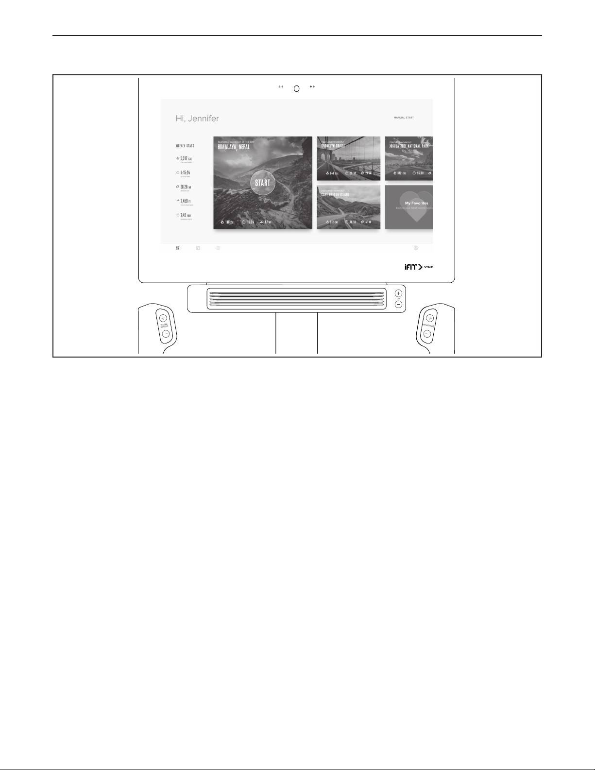
19
CONSOLE
DIAGRAM
FEATURES OF THE CONSOLE
The advanced console offers an array of features
designed to make your workouts more effective and
enjoyable.
The console features wireless technology that enables
the console to connect to iFit. With iFit, you can access
a large and varied workout library, create your own
workouts, track your workout results, and access many
other features.
In addition, the console features a selection of onboard
workouts. Each workout automatically controls the
resistance of the pedals and the incline of the frame as
it guides you through an effective exercise session.
When you use the manual mode of the console, you
can change the resistance of the pedals and the incline
of the frame with the touch of a button.
While you exercise, the console will display continuous
exercise feedback. You can even measure your heart
rate using a compatible heart rate monitor.
You can also listen to your favorite workout music or
audio books with the console sound system while you
exercise.
To turn on the power, see page 20. To learn how
to use the touch screen, see page 20. To set up
the console, see page 21.
HOW TO USE THE CONSOLE

20
HOW TO TURN ON THE POWER
IMPORTANT: If the studio cycle has been exposed
to cold temperatures, allow it to warm to room tem-
perature before you turn on the power. If you do
not do this, you may damage the console or other
electrical components.
Plug in the power cord (see
HOW TO PLUG IN THE POWER
CORD on page 16). Next,
locate the power switch on the
frame near the power cord.
Press the power switch to the
reset position (A).
The console will then turn on and be ready for use.
Note: When you turn on the power for the rst time,
the incline system may calibrate automatically. The
frame will move upward and downward as it calibrates.
When the frame stops moving, the incline system is
calibrated.
IMPORTANT: If the incline system does not
calibrate automatically, see step 6 on page 21
and manually calibrate the incline system.
HOW TO USE THE TOUCH SCREEN
The console features a tablet with a full-color touch
screen. The following information will help you use the
touch screen:
• The console functions similarly to other tablets. You
can slide or flick your finger against the screen to
move certain images on the screen, such as the
displays in a workout.
• To type information into a text box, first touch the text
box to view the keyboard. To use numbers or other
characters on the keyboard, touch ?123. To view
more characters, touch ~[<. Touch ?123 again to
return to the number keyboard. To return to the letter
keyboard, touch ABC. To use a capital character,
touch the shift button (upward-facing arrow symbol).
To use multiple capital characters, touch the shift
button again. To return to the lowercase keyboard,
touch the shift button a third time. To clear the last
character, touch the clear button (backward-facing
arrow with an X symbol).
A

21
HOW TO SET UP THE CONSOLE
Before you use the studio cycle for the first time, set up
the console.
1. Connect to your wireless network.
To use iFit workouts and to use several other
features of the console, the console must be con-
nected to a wireless network. Follow the prompts
on the screen to connect the console to your wire-
less network.
2. Customize settings.
Follow the prompts on the screen to set the desired
unit of measurement and your time zone.
Note: To change these settings later, see HOW TO
CHANGE CONSOLE SETTINGS on page 27.
3. Log into or create an iFit account.
Follow the prompts on the screen to log into your
iFit account or to create an iFit account.
4. Tour the console.
The first time you use the console, a tour
presentation will guide you through the features of
the console.
5. Check for firmware updates.
First, touch the menu button (three horizontal lines
symbol), touch Settings, touch Maintenance, and
then touch Update. The console will check for firm-
ware updates. For more information, see HOW TO
CHANGE CONSOLE SETTINGS on page 27.
6. Calibrate the incline system.
First, touch the menu button (three horizontal lines
symbol), touch Settings, touch Maintenance, and
then touch Calibrate Incline. The frame will rise
and lower as it calibrates. For more information,
see HOW TO CHANGE CONSOLE SETTINGS on
page 27.
The console is now ready for you to begin working out.
The following pages explain the workouts and other
features that the console offers.
To use the manual mode, see page 22. To use
a featured workout or an onboard workout, see
page 23. To create a draw-your-own-map work-
out, see page 25. To use an iFit workout, see
page 26.
To change console settings, see page 27. To
connect to a wireless network, see page 28. To
use the sound system, see page 29. To connect
an HDMI cable, see page 29.
Note: If there is a sheet of plastic on the screen,
remove the plastic.

22
HOW TO USE THE MANUAL MODE
1. Touch the screen or press any button on the
console to turn on the console.
See HOW TO TURN ON THE POWER on
page 20. Note: It may take a few moments for
the console to be ready for use.
2. Select the main menu.
When you turn on the console, the main menu will
appear on the screen after the console boots up.
If you are in a workout, touch the screen and follow
the prompts to end the workout and return to the
main menu. If you are in the settings menus, touch
the back button (arrow symbol) and then touch the
close button (x symbol) to return to the main menu.
3. Change the resistance of the pedals and the
incline of the frame as desired.
Touch Manual Start and begin pedaling.
You can change the resistance of the pedals by
pressing the Resistance increase and decrease
buttons on the right handlebar.
You can also change the incline of the frame by
pressing the Incline/Decline increase and decrease
buttons on the left handlebar.
Note: After you press a button, it will take a
moment for the pedals to reach the selected
resistance level or for the frame to reach the
selected incline level.
Note: When the studio cycle is declined or
extremely inclined, the range of resistance
levels may decrease.
4. Follow your progress.
The console offers several display modes. The
display mode that you select will determine which
workout information is shown.
Drag upward on the screen to enter the fullscreen
display mode. Drag downward on the screen to
view the workout information displays.
Touch the various workout information displays
to view more options. Touch the more button
(+ symbol) to view statistics or charts. Touch the
center of the screen to view even more display
mode options.
If desired, adjust the volume level by pressing the
volume increase and decrease buttons on the right
side of the console.
To pause the workout, simply touch the screen
or stop pedaling. To continue the workout, simply
resume pedaling.
To end the workout session, first touch the screen
to pause the workout. Next, touch End; a workout
summary will appear on the screen. If desired, you
can publish your results using one of the options on
the screen. Then, touch Finish to return to the main
menu.
5. Wear a compatible heart rate monitor and
measure your heart rate if desired.
You can wear a compatible heart rate monitor to
measure your heart rate. Note: The console is
compatible with all Bluetooth
®
Smart heart rate
monitors.
A compatible chest heart rate monitor is included
with some models. If a chest heart rate monitor
is included, see THE CHEST HEART RATE
MONITOR in this manual to learn how to use it.
If this model does not include a compatible heart
rate monitor, see page 29 for information about
ordering one.
The console will connect to your compatible heart
rate monitor automatically. When your heartbeat is
detected, your heart rate will be shown.

23
6. Turn on the fan if desired.
The fan has several speed settings,
including an auto mode. While the
auto mode is selected, the speed of
the fan will automatically increase
or decrease as your pedaling speed
increases or decreases. Press the
Fan increase and decrease buttons repeatedly to
select a fan speed or to turn off the fan.
Note: If the pedals are not moved for a while when
the main menu is selected, the fan will turn off
automatically.
7. When you are finished exercising, unplug the
power cord.
When you are finished exercising, press the power
switch to the off position and unplug the power
cord. IMPORTANT: If you do not do this, the elec-
trical components of the studio cycle may wear
prematurely.
HOW TO USE A FEATURED WORKOUT OR AN
ONBOARD WORKOUT
1. Touch the screen or press any button on the
console to turn on the console.
See HOW TO TURN ON THE POWER on
page 20. Note: It may take a few moments for
the console to be ready for use.
2. Select the main menu or the workout library.
When you turn on the console, the main menu will
appear on the screen after the console boots up.
If you are in a workout, touch the screen and follow
the prompts to end the workout and return to the
main menu. If you are in the settings menus, touch
the back button (arrow symbol) and then touch the
close button (x symbol) to return to the main menu.
Touch the buttons at the bottom of the screen to
select either the main menu (Home button) or the
workout library (Browse button).
3. Select a workout.
To select a workout from the main menu or the
workout library, simply touch the desired workout
button on the screen. Slide or flick the screen to
scroll upward or downward if necessary.
Note: To use a featured workout, the console must
be connected to a wireless network (see HOW
TO CONNECT TO A WIRELESS NETWORK on
page 28).
The featured workouts on your console will change
periodically. To save one of the featured workouts
for future use, you can add it as a favorite by touch-
ing the favorites button (heart symbol). You must
be logged into your iFit account to save a featured
workout (see step 3 on page 26).
To draw your own map for a workout, see HOW TO
CREATE A DRAW-YOUR-OWN-MAP WORKOUT
on page 25.
When you select a workout, the screen will show
an overview of the workout that includes details
such as the duration and distance of the workout
and the approximate number of calories you will
burn during the workout.
4. Start the workout.
Touch Start Workout to start the workout.
The workout will function in the same way as the
manual mode (see page 22).
During some workouts, an iFit coach will guide you
through a video workout. Touch the sound button
(music notes symbol) to select music, trainer voice,
and volume options for the workout.
During some workouts, the screen will show a map
of the route and a marker indicating your prog-
ress. Touch the buttons on the screen to select the
desired map options.

24
During some workouts, the screen may show a
target speed. As you exercise, keep your pedaling
speed near the target speed shown on the screen.
A message may appear prompting you to increase,
decrease, or maintain your pedaling speed.
IMPORTANT: The target speed is intended only
to provide motivation. Your actual pedaling
speed may be slower than the target speed.
Make sure to pedal at a speed that is comfort-
able for you.
If the resistance level and/or incline level is too high
or too low, you can manually override the setting
by pressing the Resistance buttons or the Incline/
Decline buttons. If you press a Resistance but-
ton, you can then manually control the resistance
level (see step 3 on page 22). If you press an
Incline/Decline button, you can then manually
control the incline level (see step 3 on page 22).
To return to the programmed resistance and/or
incline settings of the workout, touch Follow
Workout.
Note: The calorie goal shown in the workout
description is an estimate of the number of
calories that you will burn during the workout.
The actual number of calories that you burn
will depend on various factors, such as your
weight. In addition, if you manually change the
resistance level or incline level of the frame
during the workout, the number of calories you
burn will be affected.
To pause the workout, simply touch the screen
or stop pedaling. To continue the workout, simply
resume pedaling.
To end the workout, touch the screen to pause the
workout, and then follow the prompts on the screen
to end the workout and return to the main menu.
When the workout ends, a workout summary will
appear on the screen. If desired, you can select
options such as adding the workout to your sched-
ule (see HOW TO USE AN IFIT WORKOUT on
page 26) or adding the workout to your favorites
list. Then, touch Save Workout to return to the main
menu.
5. Follow your progress.
See step 4 on page 22.
6. Wear a compatible heart rate monitor and
measure your heart rate if desired.
See step 5 on page 22.
7. Turn on the fan if desired.
See step 6 on page 23.
8. When you are finished exercising, unplug the
power cord.
See step 7 on page 23.

25
HOW TO CREATE A DRAW-YOUR-OWN-MAP
WORKOUT
1. Touch the screen or press any button on the
console to turn on the console.
See HOW TO TURN ON THE POWER on
page 20. Note: It may take a few moments for
the console to be ready for use.
2. Select a draw-your-own-map workout.
When you turn on the console, the main menu will
appear on the screen after the console boots up.
If you are in a workout, touch the screen and follow
the prompts to end the workout and return to the
main menu. If you are in the settings menus, touch
the back button (arrow symbol) and then touch the
close button (x symbol) to return to the main menu.
To select a draw-your-own-map workout, touch the
Create button at the bottom of the screen.
3. Draw your map.
Navigate to the area on the map where you want
to draw your workout by typing in the search box
or by sliding your fingers on the screen. Touch
the screen to add the start point for your workout.
Then, touch the screen to add the end point for
your workout.
If you want to start and end your workout at the
same point, touch Close Loop or Out & Back in the
map options. You can also select whether you want
your workout to snap to the road.
If you make a mistake, touch Undo in the map
options.
The screen will display the elevation and distance
statistics for your workout.
4. Save your workout.
Touch Save New Workout to save your workout. If
desired, enter a title and description for your work-
out. Then, touch the continue button (> symbol).
5. Start the workout.
Touch Start Workout to start the workout. The
workout will function in the same way as a featured
workout or an onboard workout (see page 23).
6. Follow your progress.
See step 4 on page 22.
7. Wear a compatible heart rate monitor and
measure your heart rate if desired.
See step 5 on page 22.
8. Turn on the fan if desired.
See step 6 on page 23.
9. When you are finished exercising, unplug the
power cord.
See step 7 on page 23.

26
HOW TO USE AN IFIT WORKOUT
To use an iFit workout, the console must be connected
to a wireless network (see HOW TO CONNECT TO A
WIRELESS NETWORK on page 28). An iFit account
is also required.
1. Add workouts to your schedule on iFit.com.
On your computer, smartphone, tablet, or other
device, open an internet browser, go to iFit.com,
and log in to your iFit account.
Next, navigate to Menu > Library on the website.
Browse the workout programs in the library and join
the desired workouts.
Then, navigate to Menu > Schedule to view your
schedule. All of the workouts that you have joined
will appear on your schedule; you can arrange or
delete the workouts on your schedule as desired.
Take time to explore the iFit.com website before
you log out.
2. Select the main menu.
When you turn on the console, the main menu will
appear on the screen after the console boots up.
If you are in a workout, touch the screen and follow
the prompts to end the workout and return to the
main menu. If you are in the settings menus, touch
the back button (arrow symbol) and then touch the
close button (x symbol) to return to the main menu.
3. Log in to your iFit account.
If you have not already done so, touch the menu
button (three horizontal lines symbol) on the screen
and then touch Log in to log in to your iFit account.
Follow the prompts on the screen to enter your
username and password.
To switch users within your iFit account, touch
the menu button, touch Settings, and then touch
Manage Accounts. If more than one user is associ-
ated with the account, a list of users will appear.
Touch the name of the desired user.
4. Select an iFit workout that you have previously
added to your schedule on iFit.com.
IMPORTANT: Before iFit workouts will load, you
must add them to your schedule on iFit.com
(see step 1).
To load an iFit workout from iFit.com to the
console, touch the Calendar button at the bottom of
the screen.
When you load a workout, the screen will show an
overview of the workout that includes details such
as the duration and distance of the workout and
the approximate number of calories you will burn
during the workout.
5. Start the workout.
Touch Start Workout to start the workout. The
workout will function in the same way as a featured
workout or an onboard workout (see page 23).
6. Follow your progress.
See step 4 on page 22.
7. Wear a compatible heart rate monitor and
measure your heart rate if desired.
See step 5 on page 22.
8. Turn on the fan if desired.
See step 6 on page 23.
9. When you are finished exercising, unplug the
power cord.
See step 7 on page 23.
For more information about iFit, go to iFit.com.

27
HOW TO CHANGE CONSOLE SETTINGS
IMPORTANT: Some of the settings and features
described may not be enabled. Occasionally, a
firmware update may cause your console to function
slightly differently.
1. Select the settings main menu.
First, turn on the power (see HOW TO TURN ON
THE POWER on page 20). Note: It may take a
few moments for the console to be ready for use.
Next, select the main menu (Home button). When
you turn on the console, the main menu will appear
on the screen after the console boots up. If you
are in a workout, touch the screen and follow the
prompts to end the workout and return to the main
menu. If you are in the settings menus, touch the
back button (arrow symbol) and then touch the
close button (x symbol) to return to the main menu.
Then, touch the menu button (three horizontal lines
symbol) on the screen, and then touch Settings.
The settings menu will appear on the screen.
2. Navigate the settings menus and change
settings as desired.
Slide or flick the screen to scroll upward or down-
ward if necessary. To view a settings menu, simply
touch the menu name. To exit a menu, touch the
back button (arrow symbol). You may be able to
view and change settings in the following settings
menus:
Account
• MyProle
• In Workout
• Manage Accounts
Equipment
• Equipment Info
• Equipment Settings
• Maintenance
• Wi-Fi
About
• Legal
3. Customize workout settings.
To customize workout settings, touch In Workout,
and then touch the desired settings. It is
recommended that you enable the option to show
slider controls on the screen, if available.
4. Customize the unit of measurement and other
settings.
To customize the unit of measurement, the time
zone, or other settings, touch Equipment Info or
Equipment Settings, and then touch the desired
settings.
The console can display speed and distance in
either standard or metric units of measurement.
5. View machine information or console app
information.
Touch Equipment Info, and then touch Machine
Info or App Info to view information about your
studio cycle or about the console app.
6. Update the console firmware.
For the best results, regularly check for
firmware updates. Touch Maintenance, and then
touch Update to check for firmware updates using
your wireless network. The update will begin auto-
matically. IMPORTANT: To avoid damaging the
studio cycle, do not turn off the power while the
firmware is being updated.
The screen will show the progress of the update.
When the update is complete, the studio cycle will
turn off and then turn back on. If it does not, press
the power switch into the off position. Wait for sev-
eral seconds, and then press the power switch into
the reset position. Note: It may take a few minutes
for the console to be ready for use.
Note: Occasionally, a firmware update may cause
the console to function slightly differently. These
updates are always designed to improve your
exercise experience.

28
7. Calibrate the incline system.
To calibrate the incline system, touch Maintenance,
touch Calibrate Incline, and then touch Begin. The
frame will automatically rise to the maximum incline
level, lower to the minimum incline level, and then
return to the starting position. This will calibrate
the incline system. When the incline system is
calibrated, touch Finish.
IMPORTANT: Keep pets, feet, and other objects
away from the studio cycle while the incline
system is calibrating.
8. Exit the settings main menu.
If you are in a settings menu, touch the back
button. Then, touch the close button (x symbol) to
exit the settings main menu.
HOW TO CONNECT TO A WIRELESS NETWORK
To use iFit workouts and to use several other features
of the console, the console must be connected to a
wireless network.
1. Select the main menu.
First, turn on the power (see HOW TO TURN ON
THE POWER on page 20). Note: It may take a
few moments for the console to be ready for use.
Next, select the main menu (Home button). When
you turn on the console, the main menu will appear
on the screen after the console boots up. If you
are in a workout, touch the screen and follow the
prompts to end the workout and return to the main
menu. If you are in the settings menus, touch the
back button (arrow symbol) and then touch the
close button (x symbol) to return to the main menu.
2. Select the wireless network menu.
Touch the menu button (three horizontal lines
symbol), and then touch Wi-Fi to select the wire-
less network menu.
3. Enable Wi-Fi.
Make sure that Wi-Fi
®
is enabled. If it is not
enabled, touch the Wi-Fi toggle to enable it.
4. Set up and manage a wireless network
connection.
When Wi-Fi is enabled, the screen will show a
list of available networks. Note: It may take a few
moments for the list of wireless networks to appear.
Note: You must have your own wireless network
and an 802.11b/g/n router with SSID broadcast
enabled (hidden networks are not supported).
When a list of networks appears, touch the desired
network. Note: You will need to know your network
name (SSID). If your network has a password, you
will also need to know the password.
Follow the prompts on the screen to enter your
password and connect to the selected wireless
network. (To use the keyboard, see HOW TO USE
THE TOUCH SCREEN on page 20.)
When the console is connected to your wireless
network, a checkmark will appear next to the
wireless network name.
If you are having problems connecting to an
encrypted network, make sure that your password
is correct. Note: Passwords are case-sensitive.
Note: The console supports unsecured and
secured (WEP, WPA™, and WPA2™) encryption.
A broadband connection is recommended; perfor-
mance depends on connection speed.
Note: If you have questions after following
these instructions, go to support.iFit.com for
assistance.
5. Exit the wireless network menu.
To exit the wireless network menu, touch the back
button (arrow symbol).

29
HOW TO USE THE SOUND SYSTEM
Connect with an Audio Cable
To play music or audio books through the console
sound system while you exercise, plug a 3.5 mm male
to 3.5 mm male audio cable (not included) into the
jack on the right side of the console and into a jack on
your personal audio player; make sure that the audio
cable is fully plugged in. Note: To purchase an
audio cable, see your local electronics store.
Next, press the play button on your personal audio
player. Adjust the volume level by pressing the volume
increase and decrease buttons on the right side of the
console or the volume control on your personal audio
player.
Connect Your Device with Bluetooth
If the console has a Bluetooth Audio button, you can
connect your Bluetooth-compatible device to play
audio through the console sound system.
1. Place or hold your Bluetooth-compatible device
near the console.
2. Enable the Bluetooth setting on your device.
3. Pair your device to the console.
Press and hold the Bluetooth Audio button on the
console for 3 seconds. The Bluetooth Audio button
will begin flashing and the console will enter pair-
ing mode. When your device and the console pair
successfully, the audio from your device will play
through the console sound system.
Note: The console can save 8 devices in its
memory. If you have previously paired your device
to the console, you can simply press the Bluetooth
Audio button to connect your device to the console.
4. Erase the console device memory if necessary.
If you need to erase all the Bluetooth-compatible
devices saved in the console memory, press and
hold the Bluetooth Audio button for 10 seconds.
Connect Your Headphones
If the console has a headphones jack, you can plug
your headphones into the headphones jack to listen to
audio from the console through your headphones.
Connect Your Headphones with Bluetooth
If the console is enabled with this feature, you can
connect your Bluetooth-compatible headphones
to listen to audio from the console through your
headphones.
To connect your headphones to the console, first turn
on your headphones and place them near the console.
Next, select a featured workout (see page 23) or
an iFit workout (see page 26). Then, touch Connect
Bluetooth Headphones when this option appears on
the screen.
To pair your headphones to the console, select
your headphones from the list on the screen. When
your headphones and the console pair successfully,
the audio from the console will play through your
headphones.
HOW TO CONNECT AN HDMI CABLE
To show your console screen on a TV or monitor, plug
an HDMI cable (not included) into the port on the con-
sole and into a port on your TV or monitor; make sure
that the HDMI cable is fully plugged in. Note: To
purchase an HDMI cable, see your local electronics
store.
THE OPTIONAL CHEST HEART RATE MONITOR
Whether your
goal is to
burn fat or to
strengthen your
cardiovascular
system, the key
to achieving the
best results is
to maintain the
proper heart
rate during your
workouts. The optional chest heart rate monitor will
enable you to continuously monitor your heart rate
while you exercise, helping you to reach your personal
fitness goals. To purchase a chest heart rate moni-
tor, please see the front cover of this manual.
Note: The console is compatible with all Bluetooth
Smart heart rate monitors.

30
FCC INFORMATION
This equipment has been tested and found to comply with the limits for a Class B digital device, pursuant to part
15 of the FCC Rules. These limits are designed to provide reasonable protection against harmful interference
in a residential installation. This equipment generates, uses, and can radiate radio frequency energy and, if not
installed and used in accordance with the instructions, may cause harmful interference to radio communications.
However, there is no guarantee that interference will not occur in a particular installation. If this equipment does
cause harmful interference to radio or television reception, which can be determined by turning the equipment off
and on, try to correct the interference by one or more of the following measures:
• Reorient or relocate the receiving antenna.
• Increase the separation between the equipment and the receiver.
• Connect the equipment into an outlet on a circuit different from that to which the receiver is connected.
• Consult the dealer or an experienced radio/TV technician for help.
FCC CAUTION: To assure continued compliance, use only shielded interface cables when connecting to
computer or peripheral devices. Changes or modifications not expressly approved by the party respon-
sible for compliance could void the user’s authority to operate this equipment.
IMPORTANT: To satisfy exposure compliance requirements, the antenna and transmitter in the console
must be at least 8 in. (20 cm) from all persons and must not be near or connected to any other antenna or
transmitter.
Note: The console contains FCC ID: SMFOMC360526A.
31
MAINTENANCE
Regular maintenance is important for optimal
performance and to reduce wear. Inspect and properly
tighten all parts each time the studio cycle is used.
Replace any worn parts immediately.
To clean the studio cycle, use a damp cloth and a small
amount of mild soap. IMPORTANT: To avoid damage
to the console, keep liquids away from the console
and keep the console out of direct sunlight.
CONSOLE TROUBLESHOOTING
If the console does not turn on, make sure that the
power cord is fully plugged in and that the power
switch is in the reset position. If there are exterior wires
on the console, make sure that the connectors on the
wires are oriented correctly and are connected firmly.
If you are having problems connecting the console
to a wireless network or if you are having problems
with your iFit account or iFit workouts, go to
support.iFit.com.
If the Console (10) does not stay in place when it is
moved to the desired position, tighten the indicated M8
Locknut (99) slightly until the Console stays in place.
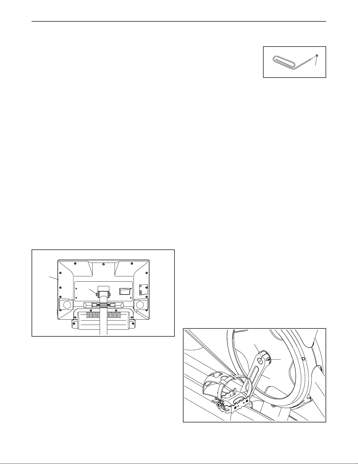
If the console does not boot
up properly, or if the con-
sole freezes and does not
respond, reset the console
to the factory default set-
tings. IMPORTANT: Doing
this will erase all custom settings you have made
to the console. Resetting the console requires two
people. First, press the power switch and unplug the
power cord. Next, locate the small reset opening (A)
near the USB port on the console. Using a bent paper
clip, press and hold the reset button inside the open-
ing, and have a second person plug in the power cord
and press the power switch. Continue holding the reset
button until the console turns on. When the reset oper-
ation is complete, the console will turn off and then turn
back on. If it does not, press the power switch off and
then on again. Once the console turns on, check for
rmwareupdates(seeHOW TO CHANGE CONSOLE
SETTINGS on page 27). Note: It may take a few
minutes for the console to be ready for use.
INCLINE SYSTEM TROUBLESHOOTING
If the frame does not move to the correct incline level,
see HOW TO CHANGE CONSOLE SETTINGS on
page 27 and calibrate the incline system.
Note: When the studio cycle is declined or extremely
inclined, the range of resistance levels may decrease.
HOW TO ADJUST THE LEFT CRANK ARM
If the Left Crank Arm (21) feels loose while you are
pedaling, tighten the two M6 x 25mm Screws (96).
Note: If you have a torque wrench, tighten one Screw
to 20 Nm (14.75 ft-lbs.), tighten the second Screw to
20 Nm, and then tighten each Screw a second time
to 20 Nm.
10
99
96
21
96
MAINTENANCE AND TROUBLESHOOTING
A
32
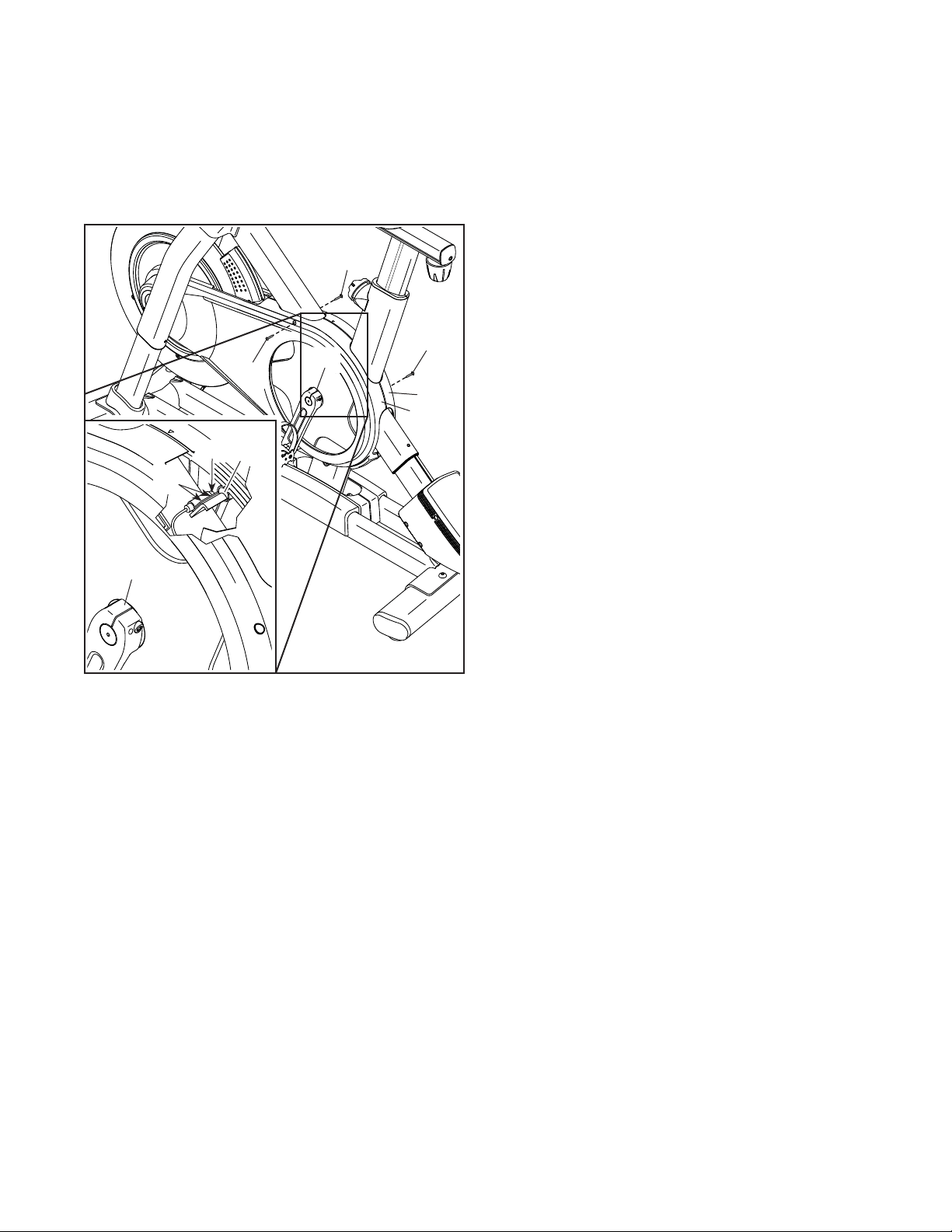
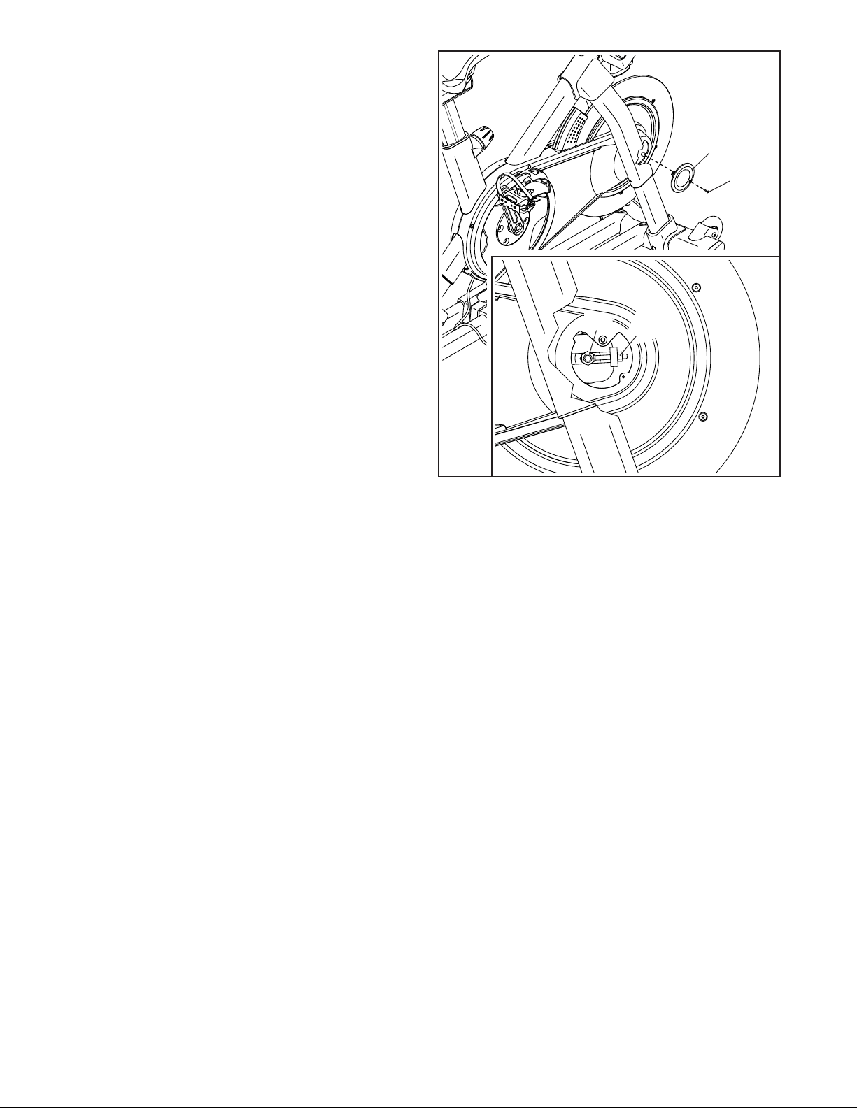
HOW TO ADJUST THE REED SWITCH
If the console does not display correct feedback, the
reed switch should be adjusted.
To adjust the reed switch, first unplug the power
cord. Next, remove the three indicated #8 x 5/8"
Screws (17) from the Right and Left Shields (30, 32).
Then, carefully pull the tops of the Right and Left
Shields (30, 32) apart a few inches.
See the inset drawing. Slightly loosen the two indi-
cated #8 x 1/2" Screws (57). Next, rotate the Left
Crank Arm (21) until a Pulley Magnet (137) is aligned
with the Reed Switch (115). Slide the Reed Switch
slightly toward or away from the Pulley Magnet. Then,
retighten the Screws.
Plug in the power cord and rotate the Left Crank Arm
(21) for a moment. Repeat these actions until the con-
sole displays correct feedback.
When the reed switch is correctly adjusted, reattach
the Right and Left Shields (30, 32).
17
30
32
17
17
21
115
83
21
137
115
57
33
HOW TO ADJUST THE DRIVE BELT
If you can feel the pedals slip while you are pedaling,
even when the resistance is adjusted to the highest
setting, the drive belt may need to be adjusted.
To adjust the drive belt, first unplug the power cord.
Then, follow the instructions below. Note: The drawings
show only the right side of the studio cycle.
Remove the indicated #8 x 5/8" Screw (17) and the
Shield Cover (31) from each side of the studio cycle.
Next, loosen the M10 Axle Nut (27) on each side of
the studio cycle, and tighten the Adjustment Nut (26)
on each side of the studio cycle one half turn. Then,
firmly retighten the M10 Axle Nuts.
Plug in the power cord and pedal the studio cycle to
test the adjustment. If necessary, repeat the above
actions until the pedals no longer slip.
When the drive belt is properly adjusted, reattach the
shield covers.
17
31
26
27
34
These guidelines will help you to plan your exercise
program. For detailed exercise information, obtain a
reputable book or consult your physician. Remember,
proper nutrition and adequate rest are essential for
successful results.
EXERCISE INTENSITY
Whether your goal is to burn fat or to strengthen your
cardiovascular system, exercising at the proper inten-
sity is the key to achieving results. You can use your
heart rate as a guide to find the proper intensity level.
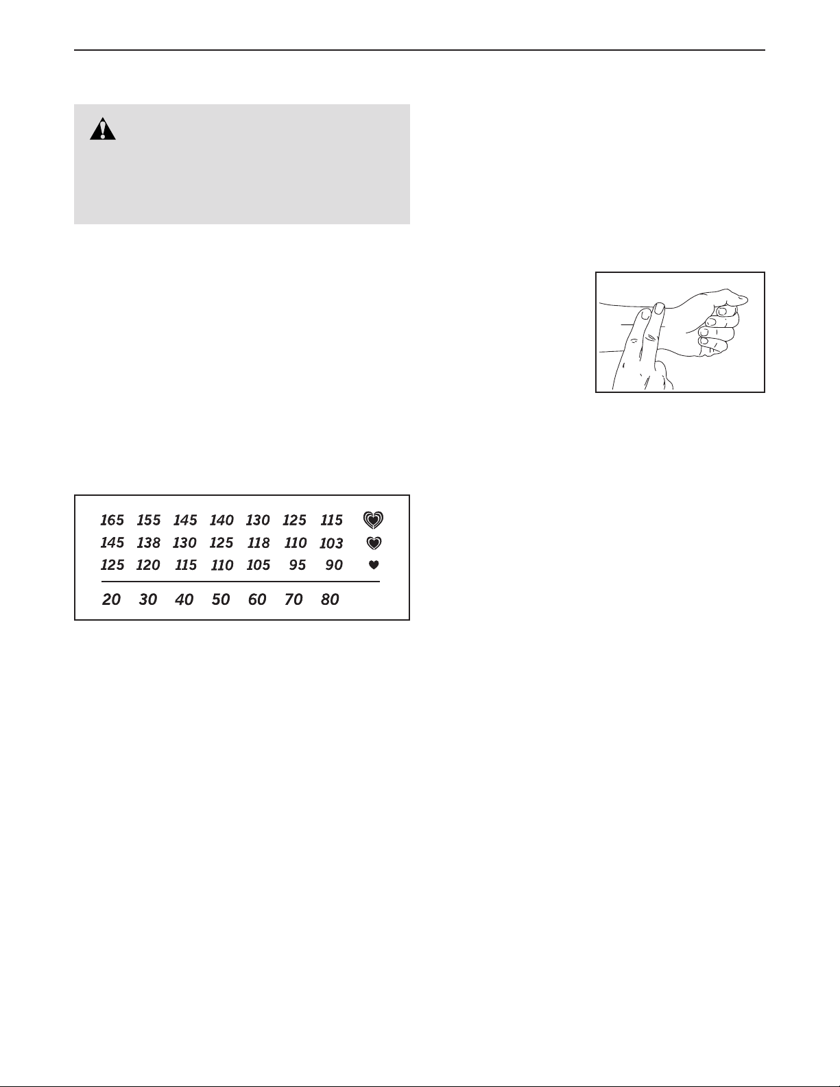
The chart below shows recommended heart rates for
fat burning and aerobic exercise.
To find the proper intensity level, find your age at the
bottom of the chart (ages are rounded off to the near-
est ten years). The three numbers listed above your
age define your “training zone.” The lowest number is
the heart rate for fat burning, the middle number is the
heart rate for maximum fat burning, and the highest
number is the heart rate for aerobic exercise.
Burning Fat—To burn fat effectively, you must exer-
cise at a low intensity level for a sustained period of
time. During the first few minutes of exercise, your
body uses carbohydrate calories for energy. Only
after the first few minutes of exercise does your body
begin to use stored fat calories for energy. If your
goal is to burn fat, adjust the intensity of your exer-
cise until your heart rate is near the lowest number in
your training zone. For maximum fat burning, exercise
with your heart rate near the middle number in your
training zone.
Aerobic Exercise—If your goal is to strengthen your
cardiovascular system, you must perform aerobic
exercise, which is activity that requires large amounts
of oxygen for prolonged periods of time. For aerobic
exercise, adjust the intensity of your exercise until
your heart rate is near the highest number in your
training zone.
HOW TO MEASURE YOUR HEART RATE
To measure your heart
rate, exercise for at
least four minutes.
Then, stop exercis-
ing and place two
fingers on your wrist
as shown. Take a
six-second heartbeat
count, and multiply the
result by 10 to find your heart rate. For example, if your
six-second heartbeat count is 14, your heart rate is 140
beats per minute.
WORKOUT GUIDELINES
Warming Up—Start with 5 to 10 minutes of stretch-
ing and light exercise. A warm-up increases your body
temperature, heart rate, and circulation in preparation
for exercise.
Training Zone Exercise—Exercise for 20 to 30 min-
utes with your heart rate in your training zone. (During
the first few weeks of your exercise program, do not
keep your heart rate in your training zone for longer
than 20 minutes.) Breathe regularly and deeply as you
exercise; never hold your breath.
Cooling Down—Finish with 5 to 10 minutes of stretch-
ing. Stretching increases the flexibility of your muscles
and helps to prevent post-exercise problems.
EXERCISE FREQUENCY
To maintain or improve your condition, complete
three workouts each week, with at least one day of
rest between workouts. After a few months of regular
exercise, you may complete up to five workouts each
week, if desired. Remember, the key to success is to
make exercise a regular and enjoyable part of your
everyday life.
WARNING: Before beginning this
or any exercise program, consult your physi-
cian. This is especially important for persons
over age 35 or persons with pre-existing
health problems.
EXERCISE GUIDELINES
35
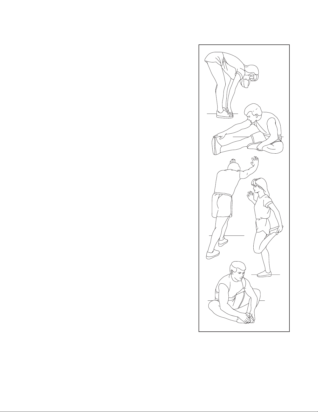
SUGGESTED STRETCHES
The correct form for several basic stretches is shown at the right. Move slowly as you stretch; never bounce.
1. Toe Touch Stretch
Stand with your knees bent slightly and slowly bend forward from
your hips. Allow your back and shoulders to relax as you reach down
toward your toes as far as possible. Hold for 15 counts, then relax.
Repeat 3 times. Stretches: Hamstrings, back of knees and back.
2. Hamstring Stretch
Sit with one leg extended. Bring the sole of the opposite foot toward
you and rest it against the inner thigh of your extended leg. Reach
toward your toes as far as possible. Hold for 15 counts, then relax.
Repeat 3 times for each leg. Stretches: Hamstrings, lower back and
groin.
3. Calf/Achilles Stretch
With one leg in front of the other, reach forward and place your hands
against a wall. Keep your back leg straight and your back foot flat on
the floor. Bend your front leg, lean forward and move your hips toward
the wall. Hold for 15 counts, then relax. Repeat 3 times for each leg.
To cause further stretching of the achilles tendons, bend your back leg
as well. Stretches: Calves, achilles tendons and ankles.
4. Quadriceps Stretch
With one hand against a wall for balance, reach back and grasp one
foot with your other hand. Bring your heel as close to your buttocks as
possible. Hold for 15 counts, then relax. Repeat 3 times for each leg.
Stretches: Quadriceps and hip muscles.
5. Inner Thigh Stretch
Sit with the soles of your feet together and your knees outward.
Pull your feet toward your groin area as far as possible. Hold for 15
counts, then relax. Repeat 3 times. Stretches: Quadriceps and hip
muscles.
1
2
3
4
5

36
Key No. Qty. Description Key No. Qty. Description
PART LIST
Model No. NTEX02117NB.6 R0320B
1 1 Frame
2 1 Base
3 1 Front Stabilizer
4 1 Rear Stabilizer
5 1 M6 Shoulder Screw
6 2 Inner Leg Sleeve
7 1 Handlebar Post
8 1 Console Support
9 1 M8 x 32mm Screw
10 1 Console
11 1 Console Bracket
12 4 M4 x 8mm Machine Screw
13 1 Saddle Post
14 2 Hand Weight
15 1 M6 Crank Screw
16 1 Pulley
17 34 #8 x 5/8" Screw
18 4 M10 x 20mm Flat Head Bolt
19 1 Crank/Right Crank Arm
20 1 Pivot Axle
21 1 Left Crank Arm
22 1 Flywheel Assembly
23 1 Handlebar Cap
24 2 Pivot Bushing
25 1 Drive Belt
26 2 Adjustment Assembly
27 2 M10 Axle Nut
28 2 Post Clamp
29 1 Right Base Cover
30 1 Right Shield
31 2 Shield Cover
32 1 Left Shield
33 1 Right Disc
34 1 Right Incline Motor Cover
35 1 Left Incline Motor Cover
36 1 Upper Incline Motor Cover
37 1 Left Disc
38 1 Hand Weight Tray
39 1 Handlebar Post Cap
40 1 Accessory Tray
41 1 M8 Saddle Screw
42 1 Saddle Nut
43 2 Carriage Cap
44 3 One-wire Grommet
45 1 Right Saddle Post Sleeve
46 1 Left Saddle Post Sleeve
47 1 Right Handlebar Post Sleeve
48 1 Left Handlebar Post Sleeve
49 2 Wheel
50 1 Adjustment Arm
51 1 Resistance Disc
52 1 Lower Saddle Clamp
53 1 Upper Saddle Clamp
54 1 Saddle
55 6 Anchored Zip Tie
56 1 Pedal Set
57 18 #8 x 1/2" Screw
58 2 Upper Leg
59 2 Lower Leg
60 4 #8 x 1/3" Screw
61 4 M8 x 15mm Screw
62 2 Outer Leg Sleeve
63 2 Frame Bearing
64 2 Leg Cover
65 1 Ground Screw
66 4 Large Leg Bushing
67 1 Carriage
68 2 Leg Spacer
69 4 Small Leg Bushing
70 1 Right Grip
71 1 Left Grip
72 1 Right Control
73 1 Left Control
74 1 Shaft Cover
75 1 Shaft Cover Sleeve
76 4 Stabilizer Cap
77 2 Foot
78 2 Leveling Foot
79 1 Controller
80 1 Controller Cover
81 4 M3 x 6mm Machine Screw
82 1 Resistance Motor
83 2 M10 x 38mm Washer
84 1 M12 x 25mm Cap Screw
85 2 Post Knob Cap
86 3 Clip Nut
87 2 Incline Motor Bushing
88 1 Incline Motor Spacer
89 1 Incline Motor
90 1 Magnet Bracket
91 1 Right Magnet Bracket Cover
92 1 Left Magnet Bracket Cover
93 4 M8 x 12mm Patch Screw
94 1 M10 x 55mm Bolt
95 2 M4 Set Screw
96 2 M6 x 25mm Screw
97 1 Handlebar
98 2 M8 x 50mm Bolt
99 3 M8 Locknut
100 2 Post Knob

37
101 1 Carriage Knob
102 4 M4 x 12mm Machine Screw
103 2 M4 x 10mm Screw
104 2 Incline Motor Sleeve
105 12 M10 x 20mm Screw
106 1 M8 x 83mm Bolt
107 2 M4 x 15mm Machine Screw
108 3 M6 Washer
109 1 Bracket Mount
110 2 Two-wire Grommet
111 2 Upper/Lower Pivot Disc
112 1 Center Pivot Disc
113 2 Inner Pivot Disc
114 2 Outer Pivot Disc
115 1 Reed Switch/Wire
116 1 Reed Switch Clip
117 1 Left Base Cover
118 1 Power Switch
119 1 Power Cord Grommet
120 1 Power Cord
121 1 Upper Brake Bushing
122 1 Lower Wire
123 1 Upper/Yellow Wire
124 1 Extension/Red Wire
125 1 Control Wire
126 2 M8 x 12mm Screw
127 8 M8 Large Washer
128 2 M5 Nut
129 1 M5 x 8mm Screw
130 1 #6 x 5/8" Screw
131 1 Adjustment Block
132 2 M4 x 10mm Blunt Screw
133 2 M10 x 20mm Hex Screw
134 1 Plastic Spacer
135 6 M10 Locknut
136 1 Shoe Pin
137 2 Pulley Magnet
138 2 M6 x 15mm Screw
139 1 Thrust Washer
140 1 Brake Knob Cap
141 1 M6 Locknut
142 1 Lower Brake Knob
143 1 Lower Brake Bushing
144 1 Spring Stop
145 1 Brake Spring
146 2 M4 x 6mm Screw
147 1 Brake Shaft
148 1 Roll Pin
149 1 E-ring
150 1 Brake Shoe
* – User’sManual
* – Assembly Tool
Key No. Qty. Description Key No. Qty. Description
Note: Specifications are subject to change without notice. For information about ordering replacement parts, see
the back cover of this manual. *These parts are not illustrated.
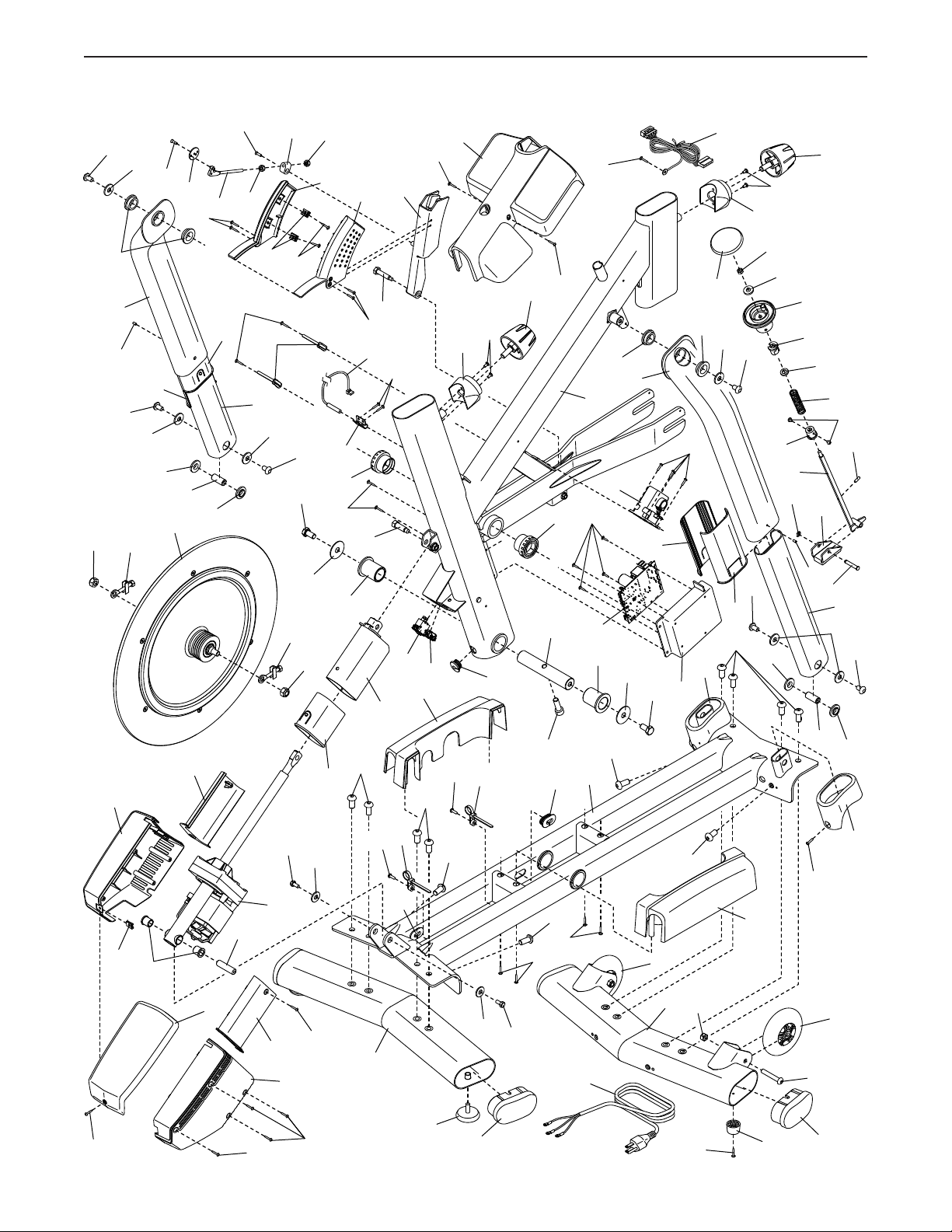
38
EXPLODED DRAWING A
Model No. NTEX02117NB.6 R0320B
1
12
12
9
20
26
26
22
24
24
83
84
83
6
133
6
79
81
82
62
59
80
2
27
27
36
35
17
87
88
89
34
17
17
17
77
17
103
64
64
69
69
4
3
78
76
76
98
99
49
29
120
17
17
105
105
138
138
108
108
86
40
44
44
74
75
58
59
66
66
58
126
143
149
147
150
136
95
148
146
145
126
61
61
127
127
127
127
66
68
62
69
69
57
55
55
65
63
63
17
17
17
17
85
85
100
57
57
115
116
118
117
119
133
104
104
49
5
50
51
128
129
130
128
131
60
60
90
92
86
57
91
100
105
105
105
105
105
127
61
61
68
57
144
121
142
108
141
140
122
44
55
95
39
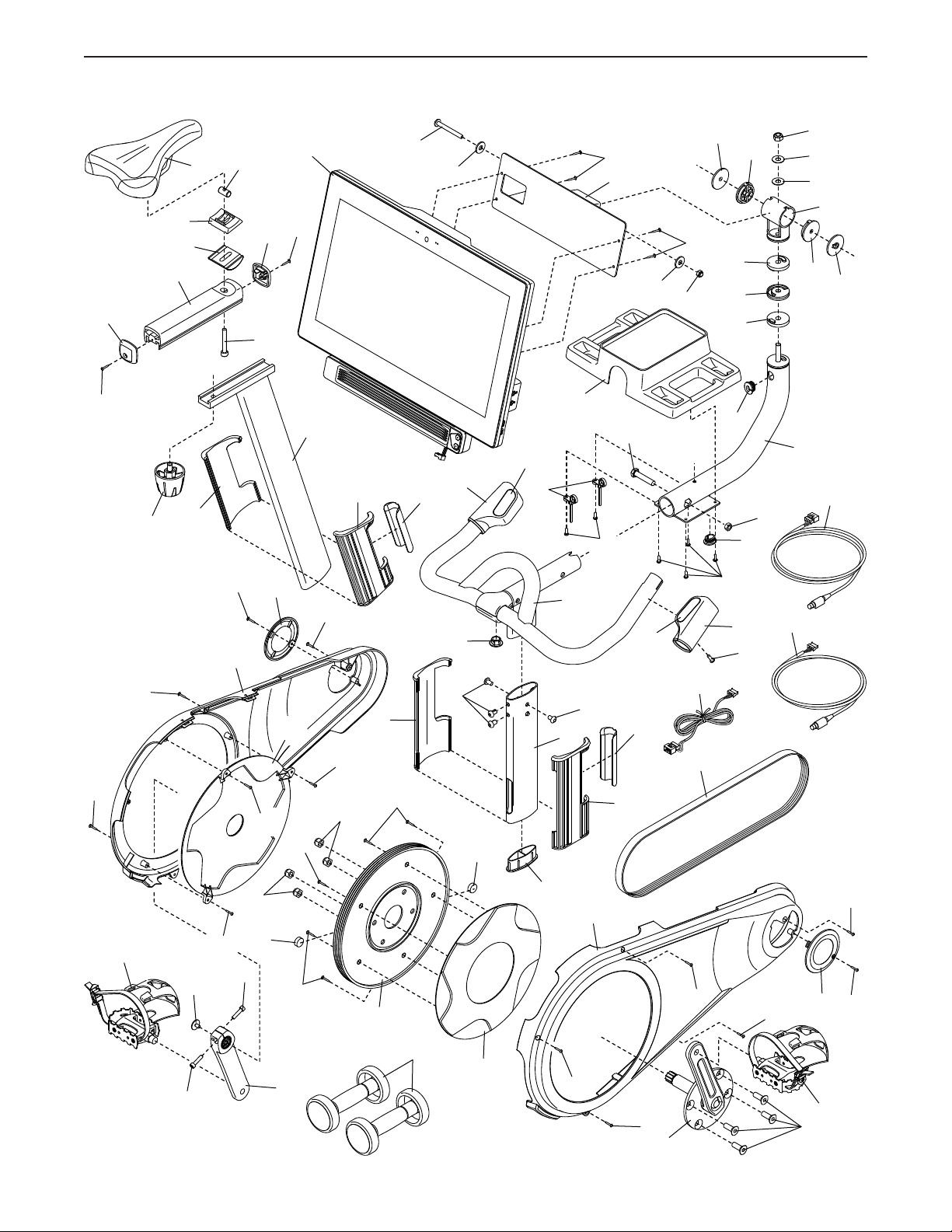
EXPLODED DRAWING B
Model No. NTEX02117NB.6 R0320B
107
101
46
45
28
107
102
11
43
42
43
52
54
53
67
41
13
10
106
99
127
127
110
110
102
113
113
135
139
134
114
114
109
123
17
8
17
70
72
71
73
97
55
94
38
111
111
112
124
17
132
132
125
28
47
25
39
30
17
17
17
17
31
17
14
33
16
135
135
21
57
57
57
32
96
96
15
56
19
56
18
17
17
17
31
48
7
93
93
23
137
137
57
57
57
37
135