Loading ...
Loading ...
Loading ...
VGZ-029 / 20120113.0 TR009 PERFORMER™ / Page 7
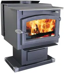
LOCATING STOVE
1. The stove must be placed on solid concrete, solid
masonry, or when installed on a combustible floor,
on an Underwriters Laboratories Listed Type 2
floor protector listed to UL standard UL 1618,
such as Hy-C or Imperial Model UL3648BK (US)
or UL4049BK (CAN). Floor protector must be
1/2˝/13mm minimum thickness (R value = 0.84,
see page 23 for calculation formulas) non-com-
bustible material or equivalent. US Requirements:
The floor protector must extend at least 16˝/41cm
beyond the front of the access door, 6˝/15.3cm
to the sides, 8˝/21cm beyond the rear and must
extend under and 2˝/50mm beyond either side of
the stove pipe connector if it is elbowed towards a
wall. (See figures 10 &11 and consult local building
codes and fire protection ordinances.) Canadian
Requirements: The floor protector must extend at
least 18˝/46cm beyond the front of the access door,
8˝/21cm to the sides, 8˝/21cm beyond the rear and
must extend under and 2˝/50mm beyond either side
of the stove pipe if it is elbowed towards a wall. (See
figures 10 & 12 and consult local building codes
and fire protection ordinances.)
CAUTION: FIRE HAZARD. CARPETING AND
OTHER COMBUSTIBLE MATERIAL SHALL
NOT COVER THE FLOOR PROTECTOR. THESE
MATERIALS MUST REMAIN OUTSIDE OF COM-
BUSTIBLE CLEARANCES, SEE FIG. 10-12
2. The room in which the stove is installed must have
a minimum floor to ceiling height of 7 ft. (2.2 m).
3. The stove must have its own flue. Do not con-
nect this unit to a chimney flue serving other
appliances. DO NOT CONNECT TO ANY AIR
DISTRIBUTION DUCT OR SYSTEM.
4. After observing the clearances to combus-
tible materials (figures 10–12), locate your floor
protector accordingly (figure 10) and care-
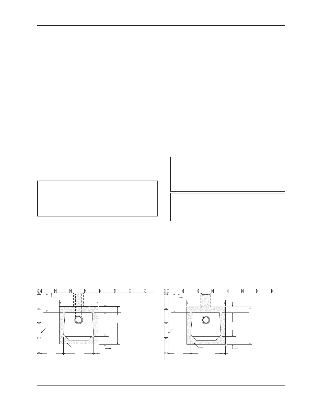
Fig. 10 – TOP VIEW Minimum Clearance Dimensions from Combustible Surfaces
FLOOR
PROTECTOR
DASHED LINES SHOW HORIZONTAL CHIMNEY CONNECTOR
AND ADDITIONAL FLOOR PROTECTOR REQUIRED BENEATH
AND EXTENDING 2” BEYOUND EACH SIDE
COMBUSTIBLE CONSTRUCTION IN ACCORDANCE WITH US NFPA 211
BACKWALL
SIDEWALL
8"min.
23"
47"
16"min.
6"min.24"
20"
min.
11"min
TOP VIEW | USA CLEARANCES
36"
Minimum
Clearances
according to
UL 1482-2006
fully place the stove in your selected location.
Install connector pipe, elbows, and thimble as
required, utilizing either a recently cleaned and
inspected 6˝/152mm lined masonry chimney or a
6˝/152mm i.d. UL 103 HT/ULC-S629 listed manu-
factured chimney.
5. Use round 6˝/152mm dia., minimum 24 MSG black
or 26 MSG blue steel stove pipe to connect the
stove to the chimney. Do not use galvanized stove
pipe. Secure connector pipe to the flue collar with
three (3) sheet metal screws. Use three screws in
each stove pipe and/or elbow joint to firmly hold the
pipe sections together. DO NOT connect this stove
to any air distribution or duct system.
6. Recheck clearances from the stove, con-
nector stove pipe, and corner clearances
using the illustrations in figures 10–12 and
your local building codes or fire protection
ordinances.
NOTE: ANY WALL CONTAINING COMBUSTI-
BLE MATERIAL SUCH AS WOODEN STUDS OR
DRYWALL AND FACED WITH BRICK OR STONE
MUST BE CONSIDERED A COMBUSTIBLE
SURFACE.
7. DO NOT install this stove in a mobile home,
Manufactured Home, Tent or trailer – NO
EXCEPTIONS! (HUD Federal Standard: 24 CFR
Ch.xx)
8. The clearances provided are minimum
dimensions set by UL standard 1482-2010 &
ULC-S627-00, tested and applied by OMNI-Test
Laboratories, Inc. the manufacturer’s testing
agency. Installation of this stove must comply
with the latest edition of NFPA 211 for reduced
clearances and/or your local building code
continued on next page
FLOOR
PROTECTOR
DASHED LINES SHOW HORIZONTAL CHIMNEY CONNECTOR
AND ADDITIONAL FLOOR PROTECTOR REQUIRED BENEATH
AND EXTENDING 2” BEYOUND EACH SIDE
COMBUSTIBLE CONSTRUCTION IN ACCORDANCE WITH US NFPA 211
BACKWALL
SIDEWALL
23"/58cm
49"/125cm
18"/46cm min.
8"/21cm min.
8"/21cm min.
24"/61cm
24"/61cm
min.
16"/
41cm
min
TOP VIEW | CANADIAN CLEARANCES
40"/
102cm
Minimum
Clearances
for Canadian
installation
according to
ULC S627
Loading ...
Loading ...
Loading ...