Loading ...
Loading ...
Loading ...
VGZ-029 / 20120113.0 TR009 PERFORMER™ / Page 5
ASSEMBLY INSTRUCTIONS
TOOLS AND MATERIALS REQUIRED
FOR INSTALLATION
tools
• Pencil
• 6 ft/2m Folding Rule or Tape Measure
• Tin Snips
• Drill: Hand or Electric
• 1/8”/3mm dia. Drill Bit (for sheet metal screws)
• Screwdrivers (blade and Phillips type)
• 10mm Nut Driver or Ratchet with 10mm Socket
• 11/16” socket or wrench
• Safety Glasses
• Gloves
materials
(NOTE: The following items are NOT included with your stove)
Flooring Protection: as specified (see page 7)
Connector Pipe: 6”/152mm dia. minimum 24 MSG black or 26
MSG blue steel straight stove pipe or elbow(s).
1/2”/13mm Sheet Metal Screws
Chimney: Existing 6”/152mm Code-approved Lined Masonry
Chimney or 6”/152mm Inside Dia. UL/ULC Listed Type HT
manufactured chimney.
Furnace Cement (manufacturer recommends Rutland Code 78
or equivalent)
CAUTION: STOVE IS HEAVY. MAKE SURE YOU
HAVE ADEQUATE HELP AND USE PROPER
LIFTING TECHNIQUES WHENEVER MOVING
STOVE.
1. Uncrate the stove and remove all cardboard and
styrofoam packing materials and protective poly
bag. Remove pedestal base, sides, front, top, ash
drawer and ash drawer support from the carton.
(Save packing materials for further assembly.)
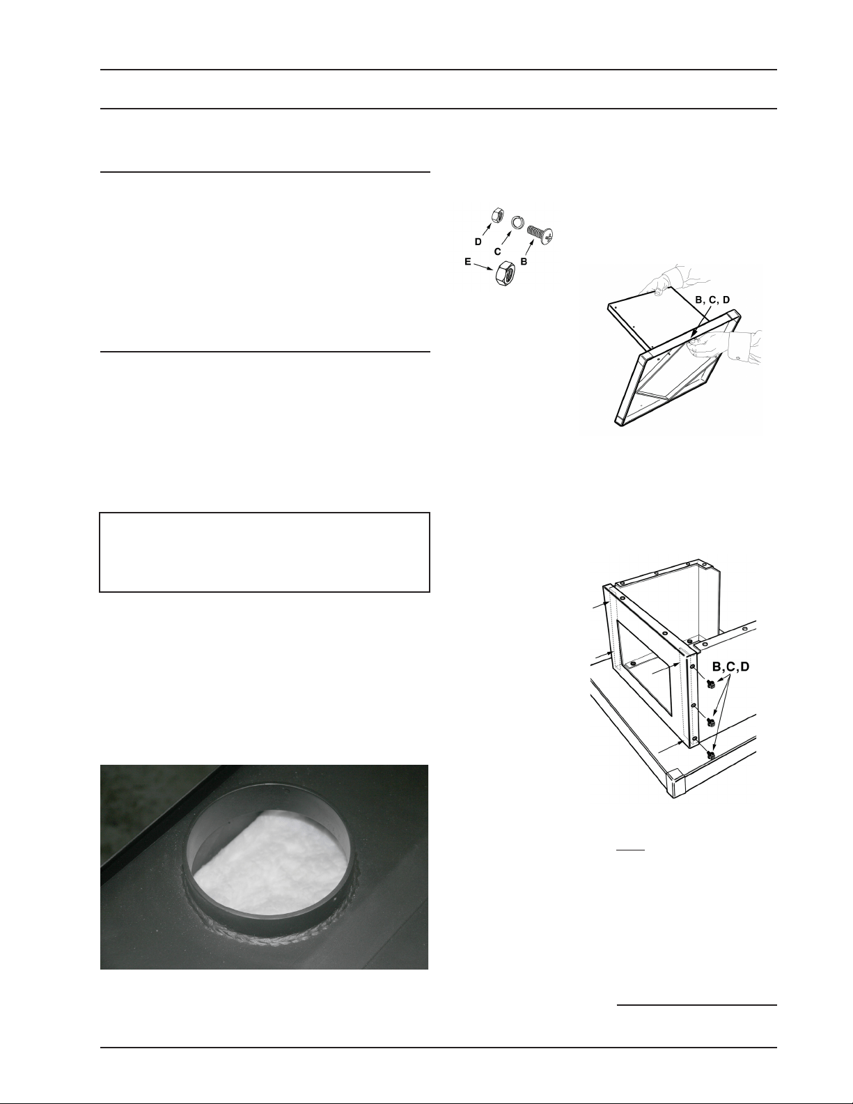
NOTICE: DO NOT remove ceramic blanket
material from inside stove pipe opening (Fig. 1).
This blanket provides an air seal on the side walls
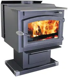
4. Attach the pedestal front frame to the sides. The
pedestal front should go over (not inside of) the side
panels. Use three (3) machine screws, lockwash-
ers & hex nuts (provided in the hardware pack) on
each side to attach both pedestal sides (#31) to the
pedestal front (#32).
5. Position ash drawer support into assembled ped-
estal (Figure 5) and secure from rear with two
(2) machine screws, lock washers and hex nuts.
Tighten all pedestal hardware.
of the stove to direct combustion gasses over the
secondary combustion tubes before exiting via the
chimney. DO NOT REMOVE the ceramic blanket
or your stove will not operate properly.
Figure 2 – Pedestal Assembly
Hardware. 1/4-20 machine screws,
lock washers & hex nuts
Figure 3 –
Assemble
sides to base
Figure 4 – Attach Pedestal
Front Frame to Sides.
(Note– front goes OVER
the side panels.)
Figure 1 – DO NOT remove ceramic blanket from
inside stove pipe opening. This is NOT packing
material but an integral component of the stove
combustion system.
NOTICE: Vogelzang International Corp. grants no warranty, stated or implied, for the installation or
maintenance of your wood stove and assumes no responsibility of any incidental or consequential damages.
2. Remove parts and hardware pack located inside
firebox.
3. Align the hole pattern of one of the pedestal sides
to the holes in the base and secure with four (4)
machine screws, lock washers and hex nuts. As-
semble the opposite side to the base. (Note: Sides
are interchangeable.)
continued on next page
DO NOT
REMOVE!
Loading ...
Loading ...
Loading ...