Loading ...
Loading ...
Loading ...
Page 10 / TR009 PERFORMER™ VGZ-029 / 20120113.0
CONNECTOR PIPE INSTALLATION
Connector pipe is used to make the connection
from the final positioning of your stove to an approved
chimney. Connector pipe is NOT included as part of
the stove. Connector pipe must be 6”/152mm diameter
minimum of 24 MSG (minimum standard gauge) black
or 26 MSG blue steel stove pipe. Any connector pipe
used must be in good condition. Replace if necessary
before using stove. Connector pipe is not rated to pro-
vide close contact to combustible materials and must
have proper clearance from combustible materials
as shown in the clearance diagrams on the previous
pages. Connector pipe should never be used in place
of a chimney. If proper clearances are not observed a
house fire could result.
INSTALLATION INSTRUCTIONS
Please Note: Installation of a flue damper is NOT
recommended. Combustion control is regulated by the
intake of combustion air, not the exhaust.
1. The crimped end of the stovepipe fits inside the
stove flue collar. Secure with three (3) sheet metal
screws. The first section of connector pipe must be
single walled to properly attach to the stove collar.
Install additional pipe and elbow with the crimped
end towards the stove. This will allow any conden-
sation in the flue to run back into the firebox.
2. Horizontal pipe runs must slope upwards
towards the chimney at least 1/4”(6.4mm) per foot
of horizontal run.
3. You must have at least 18˝/457mm of
clearance between any horizontal piping and the
ceiling.
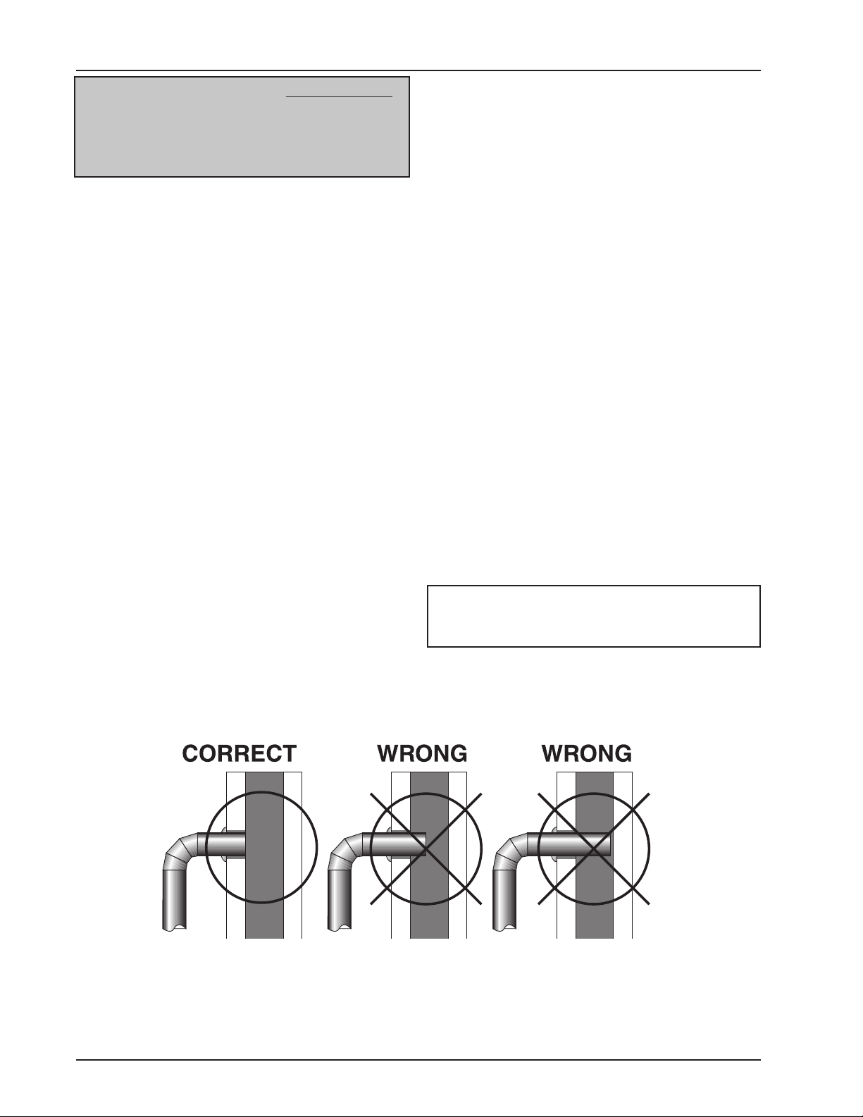
4. The pipe cannot extend into the chimney flue
(figure 14).
5. Secure pipe/elbow sections with three sheet metal
screws at each joint to make the piping rigid. Screws
may be no more than a maximum of 3˝/76mm apart.
6. It is recommended that no more than two (2)
90° bends be used in the stovepipe installa-
tion. The use of more than two 90° bends may
decrease the amount of draw and possibly
cause smoke spillage. Where possible, use only
corrugated (non adjustable) elbows. These
provide a better seal.
7. The connector pipe must not pass through an
attic or roof space, trusses, closet, or any con-
cealed space, floor, ceiling, wall, or combustible
construction. (See Chimney Connector Systems
& Clearances, page 14.) A UL 103 HT (USA)/
ULC-S629 (CDN) Listed chimney system must be
used from the first penetration of ceiling or wall to
the chimney cap.
Where passage through a wall or partition of com-
bustible construction is desired, the installation shall
conform to NFPA 211 (USA) or CAN/CSA-B365
(Canada).
WARNING: DO NOT USE SINGLE WALL CON-
NECTOR PIPE AS A CHIMNEY - A HOUSE FIRE
COULD RESULT.
Figure 14 – Stovepipe/Flue Connections
NOTE: CONNECTOR PIPE IS NOT INCLUDED.
TO PURCHASE, VISIT YOUR LOCAL HARD-
WARE, HOME, OR BUILDING CENTER.
SEE “LOCATING STOVE” PAGE 7 FOR
ADDITIONAL SPECIFICATIONS.
Loading ...
Loading ...
Loading ...