PROJECTION COLOR TV
OPERATING GUIDE
_ w
IMPORTANT SAFEGUARDS
FIRST TIME USE
THE GENIUS
REMOTE CONTROL
2-4
5-18
19-30
ULTRATEC BIT-MAP
ON-SCREEN DISPLAY
31-59
__,_ _"
USEFUL INFORMATION INDEX 60-67
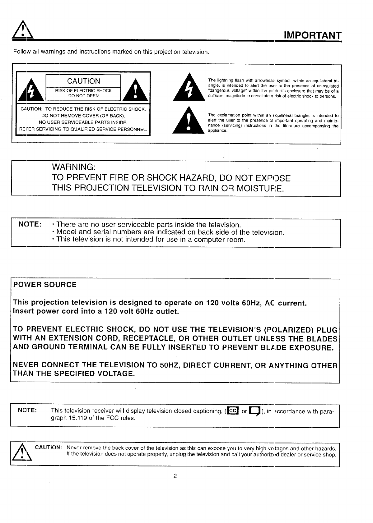
Follow all warnings and instructions marked on this projection television.
IMPORTANT
[__t CAUTION ],_
RISK OF ELECTRIC SHOCK
DO NOT OPEN
CAUTION: TO REDUCE THE RISK OF ELECTRIC SHOCK,
DO NOT REMOVE COVER (OR BACK).
NO USER SERVICEABLE PARTS INSIDE.
REFER SERVICING TO QUALIFIED SERVICE PERSONNEL.
The lightning flash with arrowheacl symbol, within an equilateral tri-
angle, is intended to alert the us_=rto the presence of uninsulated
"dangerous voltage" within the prcduct's enclosure that may be of a
sufficient magnitude 1oconstitute a risk of electric shock to persons.
The exclamation point within an equilateral triangle, is intended to
alert the user to the presence of important operating and mainte-
nance (servicing) instructions in the literature accompanying the
appliance.
WARNING:
TO PREVENT FIRE OR SHOCK HAZARD, DO NOT EXPOSE
THIS PROJECTION TELEVISION TO RAIN OR MOISTLIRE.
NOTE:
• ]here are no user serviceable parts inside the television.
• Model and serial numbers are indicated on back side of the television.
• ]his television is not intended for use in a computer room.
POWER SOURCE
This projection television is designed to operate on 120 volts 60Hz, AC: current.
Insert power cord into a 120 volt 60Hz outlet.
TO PREVENT ELECTRIC SHOCK, DO NOT USE THE TELEVISION'S (POLARIZED) PLUG
WITH AN Ex"rENSlON CORD, RECEPTACLE, OR OTHER OUTLET UNL.ESS THE BLADES
AN[) GROUND TERMINAL CAN BE FULLY INSERTED TO PREVENT BLADE EXPOSURE.
NEVER CONNECT THE TELEVISION TO 50HZ, DIRECT CURRENT, OR ANYTHING OTHER
THAN THE SPECIFIED VOLTAGE.
NOTE: This television receiver will display television closed captioning, (r_ or E_), in accordance with para- _1
graph 15.119 of the FCC rules.
I
,_. _ CAUTION: N_v_rr_m_v_th_ba_kc_v_fth_t_vi_i_na_thiscanexp_y_ut_v_ryhighv_tag_an_therh_z_r_ I
If the television does not operate properly, unplug the television and call your authorized dealer or service shop.
2
SAFETY TIPS
IMPORTANT SAFEGUARDS
CAUTION:
• Read all of these instructions.
• Save these instructions for later use.
• Follow all warnings and instructions marked
on the television.
SAFETY POINTS YOU SHOULD KNOW ABOUT
YOUR HITACHI PROJECTION TELEVISION
Our reputation has been built on the quality, performance, and ease of service of HITACHI televisions
Safety i.,;also foremost in our minds in the design of these units. To help you operate these products properly, this section illustrates safety tips which
will be of benefit to you. Please read it carefully and apply the knowledge you obtain from it to the proper operation of your HITACHI television.
Please fill out your warranty card and mail it to HITACHI. This will enable HITACHI to notify you promptly in the impr3bable event that a safety
problem should be discovered in your product model.
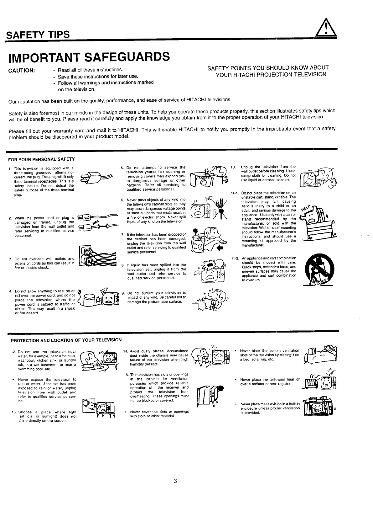
FOR YOUR PERSONAL SAFETY
1. This leevision is equippecl with a
three-plong grounded, alternating-
current ine plug. This plug will fit only
three terminal receptacles. This is a
safety :eature. Do not defeat the
safety purpose of the three terminal
plug.
......r'--"_ _
2. When the power cord or plug is
damag,.=d or frayed, unplug the
television from the wall outlet and
refer s,_rvicing to qualified service
personnel.
3. Do nol overload wall outlets and
extensi 3n cords as this can result in
fire or electric shock.
4. Do not allow anything to rest on or
roll over the power cord, and do not 9.
place the television wl'ere the
power cord is subject to traffic or
abuse. This may result in a shock
or fire ;_azard.
Do not attempt to service the
television yoursetl as opening or
removing covers may expose you
to dangerous voltage or other
hazards. Refer all servicing to
qualified service personnel.
Never push objects of any kind into
the television's cabinet slots as they
may touch dangerous voltage points
or short out parts that could result in
a fire or electric shock. Never spill
liquid of any kind on the television.
If the television has been dropped or
the cabinet has been damaged,
unplug the television from the wall
outlet and refer servicing to qualified
service personnel.
If liquid has been spilled into the
television set, unplug it from the
wall outlet and refer service to
qualified service personnel.
Do not subject your television to
impact of any kind. Be careful not to
damage the picture tube surface.
10. Unplug the televisio'l from the 1----_.
wall outlet before cle_ning. Use a
damp cloth for ceaning+ Do not
use liquid or aerosol ,_leaners.
11-1. Do not place the tele/ision on an
_.,_OI. unstable cart, stand, <)rtable. The
__ television may fa I, causing
serious injury to a child or an
adult, and serious damage to the _x"_l[ _
appliance. Use o3ly with a cart or
stand recommendE!d by the .B,/_#.-_ j|li_.. "
manufacturer, or scld with the
television. Wall o,"sh _ff mounting
should lollow the m_nufacturer's
instructions, and should use a
mounting kLt appro/ed by the
manufacturer.
1t-2. An appliance and carl combination
ocf_ _) should be moved with care.
o _ Qu_ck stops, excessi_,e force, and
_;.t" .'- <" _1ol| uneven surfaces may cause the
appliance and cart combination
to overturn.
PROTEI3TION AND LOCATION OF YOUR TELEVISION
12. Do rot use the television near
water, for example, near a bathlub,
wash:_owl, kitchen sink, or laundry
tub, i3 a wet basement, or near a
swim'ning pool, etc.
Never expose the '_elevision to
rain or water. If the set has been
expo_,ed to rain or water, unplug
television from wall oJtlet and
refer to qualified service person-
nel.
13 Choose a place where Fight
(artilcia] or sunlight) does not
shine directly on the screen.
14.
15.
dust inside the chassis may cause
failure of the television when high
humidity persists.
The television has slots or opemngs
in the cabinet for ventilation
purposes which provide reliable
operation of the receiver and
protect the television trom
overheating. These openings must
not be blocked or covered.
Never cover the slots or openings
with cloth or other material.
• Never block the bottom ventilation r I_i,_1_
slots of the television by placing it on
a bed. sofa, rug, etc.
• Never place the :e]e','ision near or __
over a radiator or hea: register.
Never place the teevi., ion in a built-in
enclosure unless pro;_er ventilation
is provided.
/.k
PROTECTION AND LOCATION OF YOUR TELEVISION
SAFETY TIPS
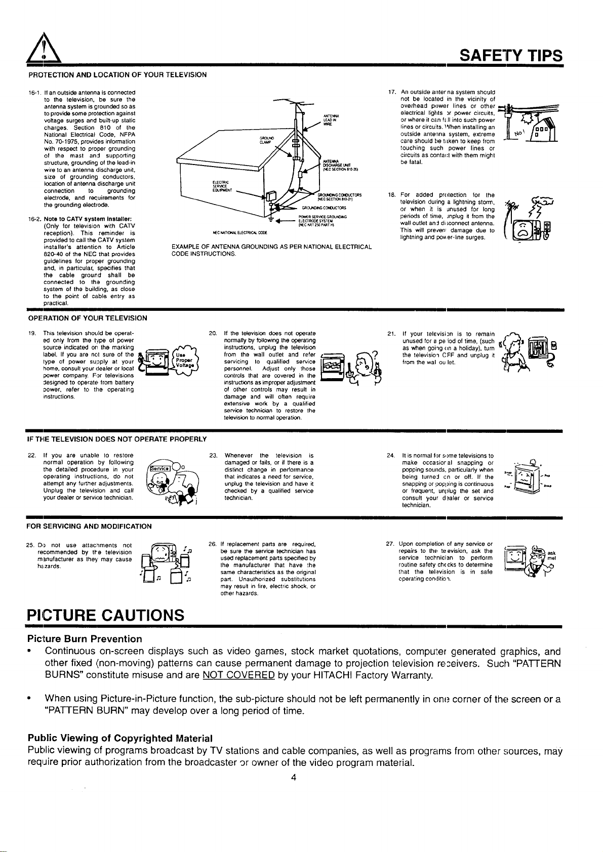
16-1. Ifan outside antenna is connected
to the television, be sure the
antenna system is grounded so as
to provide some protection against
voltage surges and built-up static
charges. Section 810 of the
National Electrical Cede, NFPA
No. 70-1975, provides information
with respect to proper grounding
of the mast and supporting
structure, grounding of the lead-in
wire to an antenna discharge unit,
size of grounding conductors,
location of antenna discharge unit
connection to grounding
electrode, and requirements for
the grounding electrode.
16-2. Note to CATV system installer:
(Only for television with CATV
reception). This reminder is
provided to call the CATV system
installer's attention to Article
820-40 of the NEC that provides
guidelines for proper grounding
and, in particular, specifies that
the cable ground shall be
connected to the grounding
system of the building, as close
to the point of cable entry as
practical.
_rrEt_W
[_so._R6_UNIT
(NE¢ 9ECTICt_ 810-_ I
C4_OUNO_G¢_O_:TO_S
_ECSEC1_ONate-21)
GROUNO_CO_DOCT_$
_R SERVI(_¢,_JNO_
ELECTRCOIE SYSTEM
{NEC _T 250 PART H)
NEC _TK_L ELECTR_.AL
EXAMPLE OF ANTENNA GROUNDING AS PER NATIONAL ELECTRICAL
CODE INSTRUCTIONS.
17. An outside allferna system should
not be located in the vicinity of
overhead power lines or other ,__
electrical lights :,r power circuits, [_
or where il C_Lnf_ll into such power _" _
Iines or circuits. When installing an U ._, fouo_
outside antenna system, extreme L_° ...L_,_
care should f)e f=Lkento keep from
touching such power lines or
circuits as conta(:t with them might
be fatal.
18. For added pr(Itection for the
television duzing a lightning storm,
or when it is unused for long
periods of time, Jnplug it from the
wall outlet an::l di:;connect antenna.
This will precen_ damage due to
lightning and pov,er-line surges.
OPERATION OF YOUR TELEVISION
19. This television should be operat-
ed only from the type of power
source indicated on the marking
label. If you are not sure of the
lype of power su;_ply at your
home, consult your dealer or local
power company. For televisions
Jesigned to operate from battery
Dower, refer to the operating
instructions.
20. Ifthe letevision does not operate
normally by following the operating
instructions, unplug the lelevision
from the wall Outlet and refer
servicing Io qualilied service
personnel. Adjust only those
controls that are covered in the
instructions as improper adjustment
of other controls may result in
damage and will often require
extensive work by a qualified
service technician to restore the
television to normal operation.
21. If your television is to remain __~r'_ __,
unused for a pe iod of time, (such
as when going (m a holiday), turn
the television CFF and unplug it "
from the wal ou let.
IF THE TELEVISION DOES NOT OPERATE PROPERLY
22. If you are unable to restore
normal operation by following
the detailed procedure in your
operating instructions, do not
attempt any further adjustments.
Unplug the television and call
your dealer or servh..e technician.
23. Whenever the television is
damaged or fails, or if there is a
distinct change in performance
that indicates a need for service.
unplug the television and have it
checked by a qualified service
technician.
24. It is normal for some televisions to
make occasioral snapping or
popping sounds, particularly when
being turne:l cn or off. If the
snapping or i.;,opping is continuous
or frequent, unplug the set and
consult your d_aler or service
technician.
FOR SERVICING AND MODIFICATION
25. DO not use attaclnments not
recommended by tl'e television
manufacturer as they may cause
h_zards.
,,f_ 26. If replacement parts are required, 27. Upon completion of any service or l ""
'[_ be sure the service technician has repairs to the teevislen, ask the ,c.--...-_ . ask
used replacement parts specified by service technician to perform me!
the manufacturer that have the routine safety ch,_cks to determine
same characteristics as the original that the television is in safe
part. Unaulhorized substitutions operating condition.
may resull in fire, electric shock, or
other hazards.
PICTURE CAUTIONS
Picture Burn Prevention
e Continuous on-screen displays such as video games, stock market quotations, compule_ generated graphics, and
other fixed _inon-moving) patterns can cause permanent damage to projection television re;eivers. Such "PATTERN
BURNS" constitute misuse and are NOT COVERED by your HITACHI Factory Warranty.
* When using Picture-in-Picture function, the sub-picture should not be left permanently in one corner of the screen or a
"PATTERN BURN" may develop over a long period of time.
Public Viewing of Copyrighted Material
Public viewing of programs broadcast by TV stations and cable companies, as well as programs from other sources, may
require prior authorization from the broadcaster 9r owner of the video program rnaterial.
4
ACCESSORIES
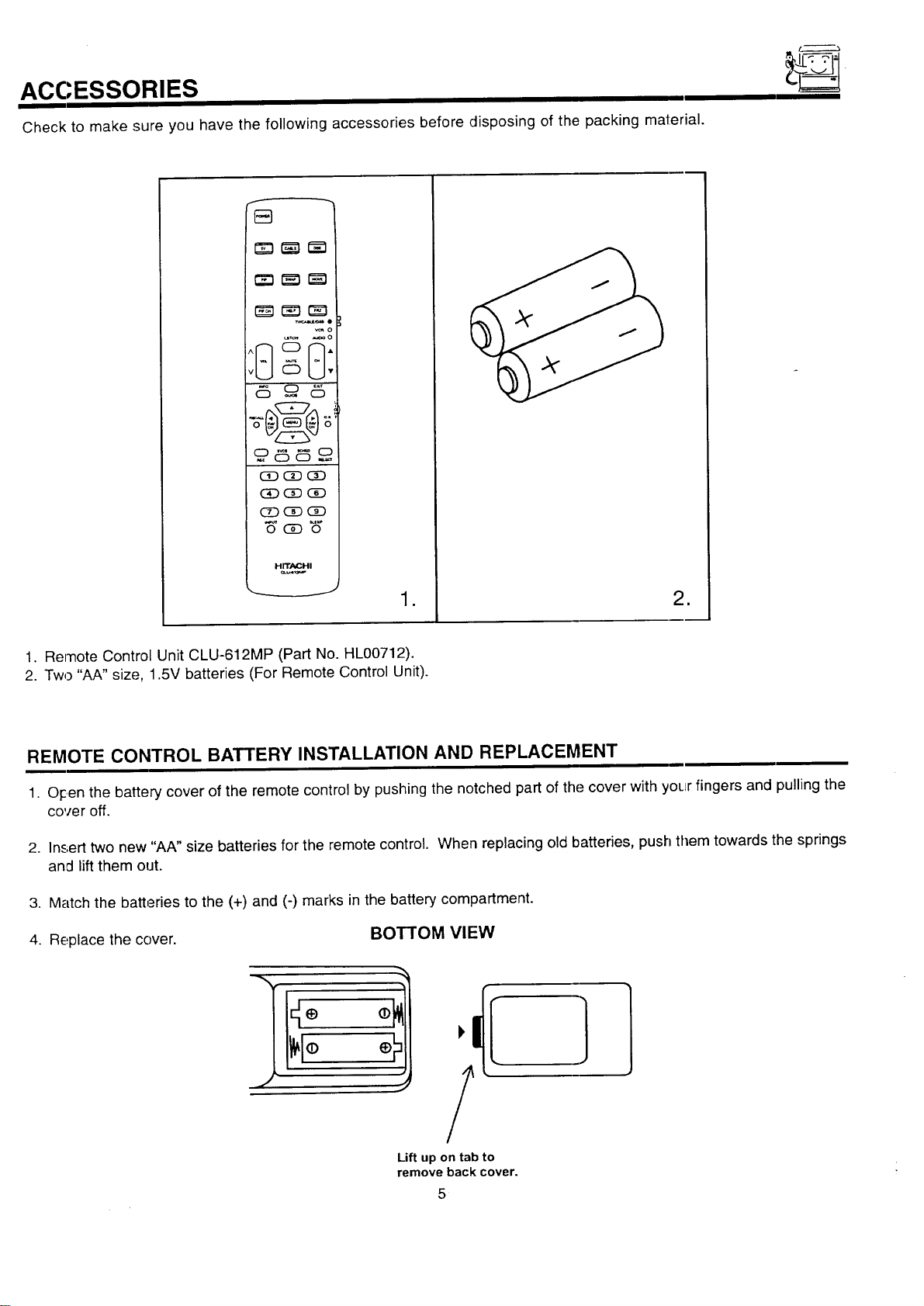
Check to make sure you have the following accessories before disposing of the packing material.
_o
_o
_ _ o
_ CiDCD
_CiD_
H rrAP_l-ii
,._ .J
o
=
1. Remote Control Unit CLU-612MP (Part No. HL00712).
2. Two "AA" size, 1.5V batteries (For Remote Control Unit).
REMOTE CONTROL BATTERY INSTALLATION AND REPLACEMENT
1. O_centhe battery cover of the remote control by pushing the notched part of the cover with your fingers and pulling the
cover off.
2. Insert two new "AA" size batteries for the remote control. When replacing old batteries, push them towards the springs
and lift them out.
3. Match the batteries to the (+) and (-) marks in the battery compartment.
4. Replace the cover. BOTTOM VIEW
:!1,/IE
Lift up on tab to
remove back cover.
5
ANTENNA
HOW TO SET UP YOUR NEW HITACHI PROJECTION TV
Unless your TV is connected to a cable TV system or to a centralized antenna system, a good outdoor color "TV antenna is
rec:ommended for best performance. However, if you are located in an exceptionally good signal area ":h_.tisfree from interference and
mLJltipleimage ghosts, an indoor antenna may be sufficient.
LOCATION
Select an area where sunlight or bright indoor illumination will not fall directly on the picture, screen. Also, be sure that the location
selected allows a free flow of air to and from the perforated back cover of the set.
To avoid cabinet warping, cabinet color changes, and increased chance of set failure,, do not place the TV where temperatures can
become excessively hot, for example, in direct sunlight or near a heating appliance, etc.
VIFWING
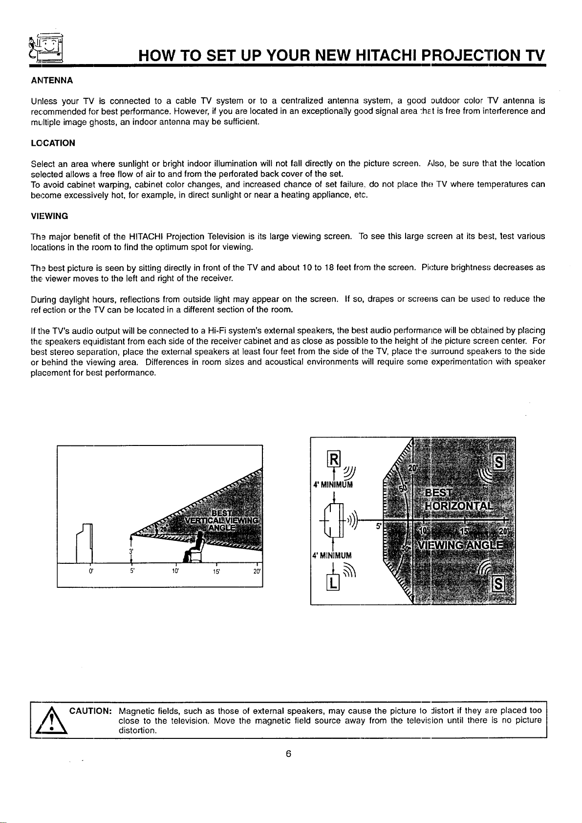
Th_ major benefit of the HITACHI Projection Television is its large viewing screen. "Tosee this large screen at its beast,test various
locations in the room to find the optimum spot for viewing.
Th_= best picture is seen by sitting directly in front of the TV and about 10 to 18 feet from the screen. Pi_'ture brightness decreases as
the viewer moves to the left and right of the receiver.
During daylight hours, reflections from outside light may appear on the screen. If so, drapes or screens can be usecl to reduce the
refection or the TV can be located in a different section of the room.
Ifthe TV's audio output will be connected to a Hi-Fi system's external speakers, the best audio performance will be obtained by placing
the speakers equidistant from each side of the receiver cabinet and as close as possible to the height of Lhepicture screen center. For
be=3tstereo separation, place the external speakers at least four feet from the side of the TV, place the :surround speakers to the side
or behind the viewing area. Differences in room sizes and acoustical environments will require some experimentation with speaker
placement for best performance.
0' 5' 10'
4' MINIMUM
4' MINIMUM
I
A CAUTION: Magnetic fields, such as those of external speakers, may cause the picture lo :listort if they are placed too I
close to the television. Move the magnetic field source away from the television until there is no picture
I
_";.,.._ distortion.
HOOK-UP CABLES AND CONNECTORS
Most video/audio connections between components can be made with shielded video and audio cables that have phono connectors.
For be.,;tperformance, video cables should use 75-Ohm coaxial shielded wire. Cables can be purchased from most stores that sell
audio/video products. Below are illustrations and names of common connectors. Before purchasing any cables, be sure of the output
and input connector types required by the various components and the length of each cable.
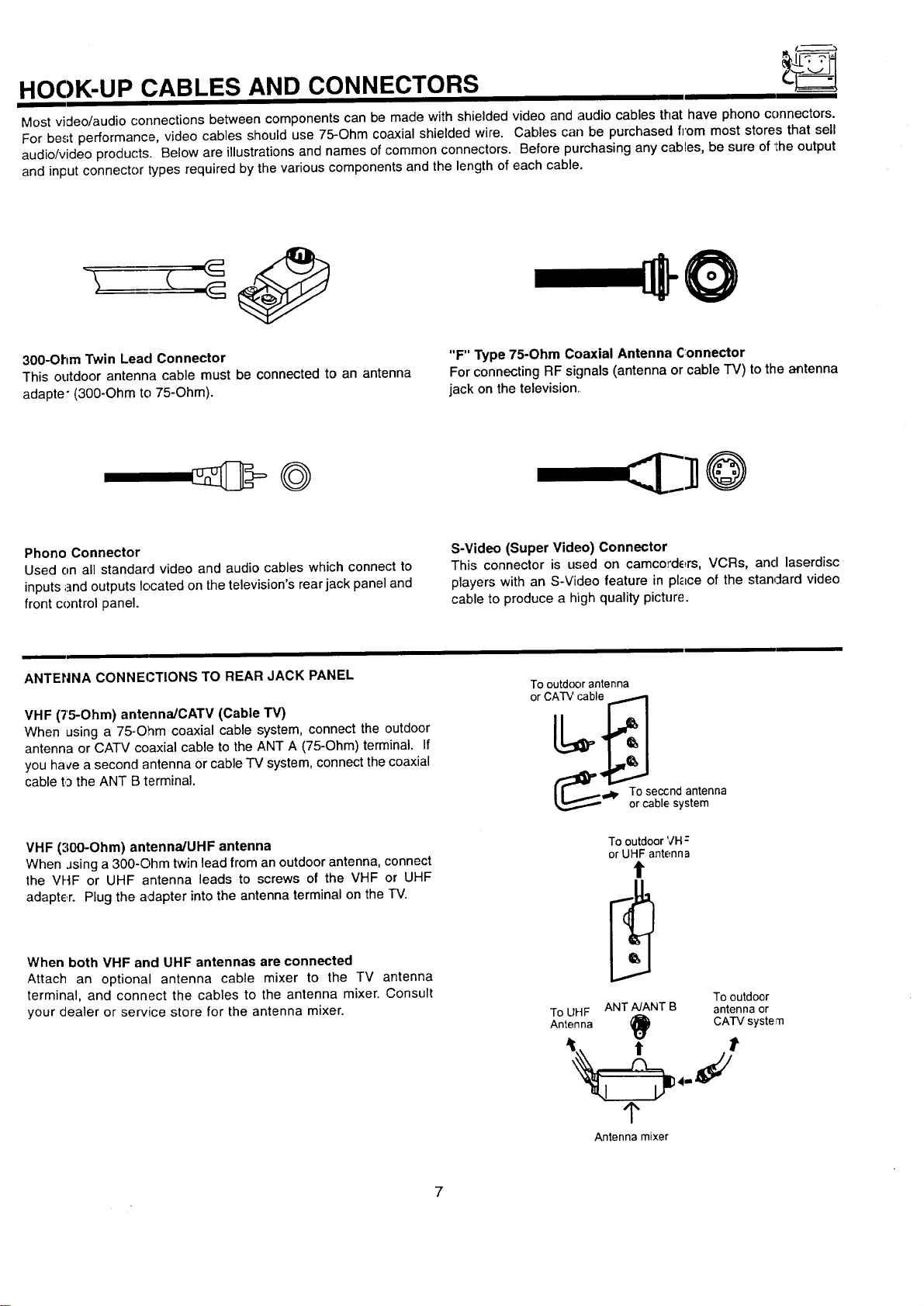
300-Ohm Twin Lead Connector
This outdoor antenna cable must be connected to an antenna
adapter (300-Ohm to 75-Ohm).
"F" Type 75-Ohm Coaxial Antenna Connector
For connecting RF signals (antenna or cable "IV) to the antenna
jack on the television.,
Phono Connector
Used on all standarcl video and audio cables which connect to
inputs ;]nd outputs located on the television's rear jack panel and
front control panel.
S-Video (Super Video) Connector
This connector is used on camcorders, VCRs, and laserdisc
players with an S-Video feature in place of the stan4ard video
cable to produce a high quality picture.
ANTENNA CONNECTIONS TO REAR JACK PANEL
VHF (75-Ohm) antenna/CATV (Cable "rv)
When using a 75-Ohm coaxial cable system, connect the outdoor
antenna or CATV coaxial cable to the ANT A (75-Ohm) terminal. If
you hace a second antenna or cable TV system, connect the coaxial
cable to the ANT B terminal.
VHF ('100-Ohm) antenna/UHF antenna
When Jsinga 300-Ohm twin lead from an outdoor antenna, connect
the VHF or UHF antenna leads to screws of the VHF or UHF
adapter. Plug the adapter into the antenna terminal on the TV.
When both VHF and UHF antennas are connected
Attach an optional antenna cable mixer to the TV antenna
terminal, and connect the cables to the antenna mixer. Consult
your dealer or service store for the antenna mixer.
Tooutd(_orantenna
orCATVcable
(_' oT°¢_qeb,c_:nsysatntenna
To outdoor VH:
or UHF antenna
t
Tooutdoor
ToUHF ANTNANT B antennaor
Antenna _) CATV systern
_r
Antenna mixer
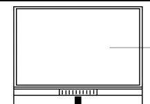
FRONT PANEL CONTROLS
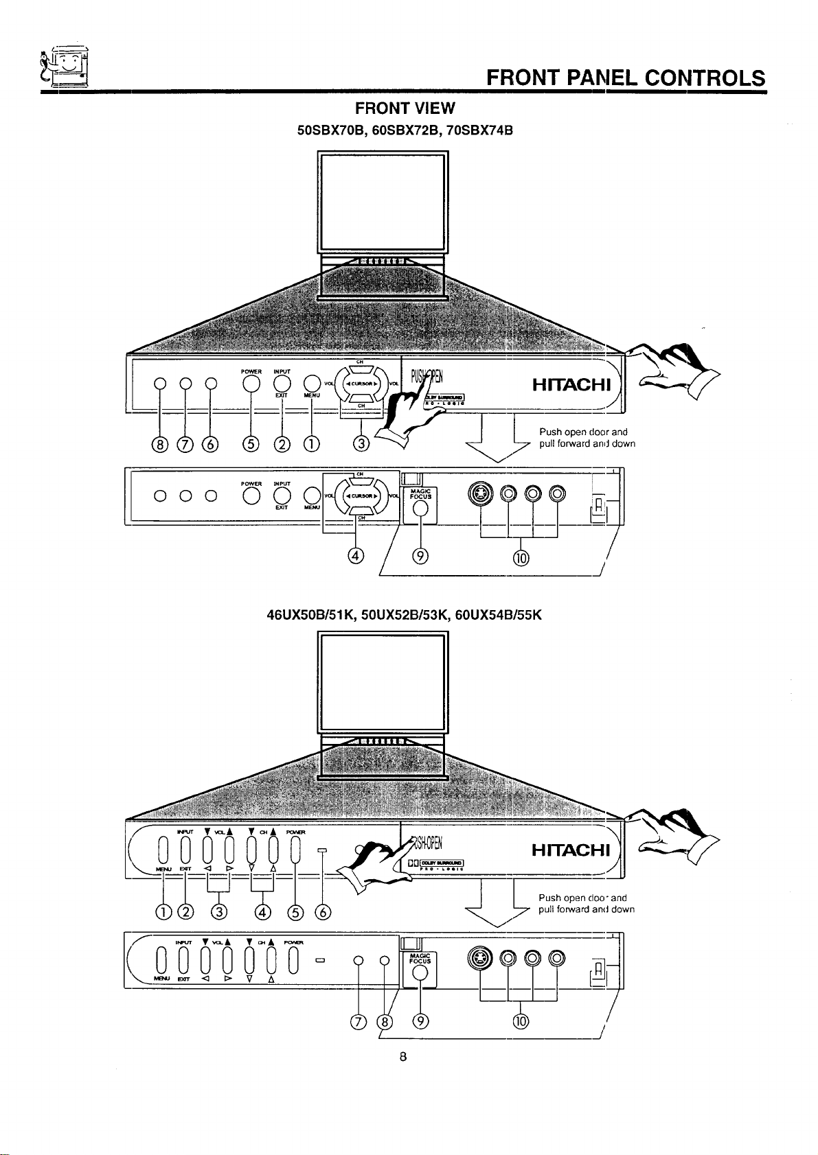
FRONT VIEW
50SBX70B, 60SBX72B, 70SBX74B
HITACHI
O O O
pOWER
O
INPUT
O
E.Y3T
Push open door and
pull forward and down
I
/
46UX50B/51K, 50UX52B/53K, 60UX54B/55K
HITACHI
.[
Push open doo" and
/7 pull forward and down
I
FRC)NT PANEL CONTROLS
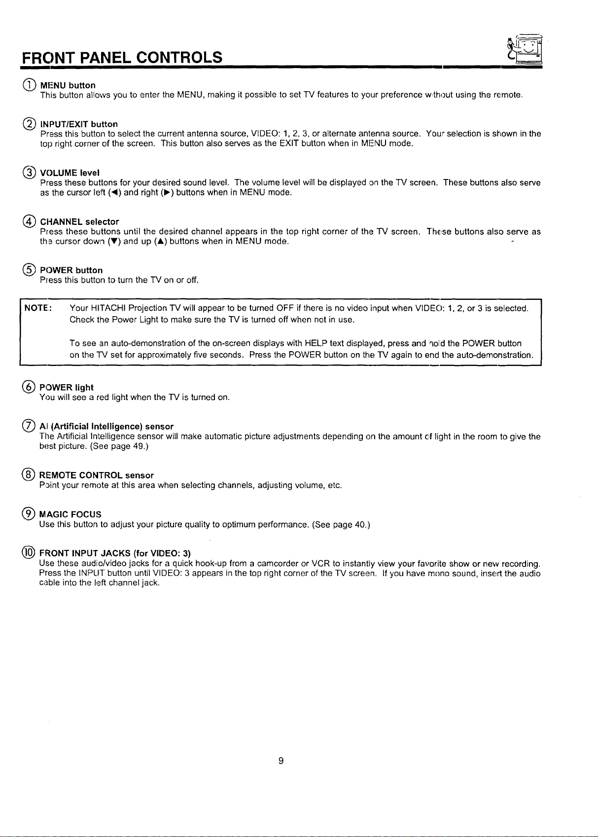
(_ MF-NU button
This button allows you to enter the MENU, making it possible to set -IV features to your preference w,thout using the remote.
(_) INPUT/EXIT button
Press this button to select the current antenna source, VIDEO: 1, 2, 3, or alternate antenna source. Your selection is shown in the
top right corner of the screen. This button also serves as the EXIT button when in MFNU mode.
____VOLUME level
Press these buttons for your desired sound level. The volume level will be displayed on the "IV screen. These buttons also serve
as the cursor left ('4) and right (1_) buttons when in MENU mode.
(_) CI-IANNEL selector
Press these buttons until the desired channel appears in the top right corner of the TV screen. "l"hE_sebuttons also serve as
th_ cursor dowl'l (Y) and up (A) buttons when in MENU mode.
(_) POWER button
Press this button to turn the TV on or off.
NOTE:
Your HITACHI Projection TV will appear to be turned OFF if there is no video input when VIDE(): 1, 2, or 3 is selected.
Check the Power Light to make sure the TV is turned off when not in use.
To see an auto-demonstration of the on-screen displays with HELP text displayed, press and qold the POWER button
on the "I-V set for approximately five seconds. Press the POWER button on the TV again to end the auto-demonstration.
(_ POWER light
You will see a red light when the -IV is turned on.
/_ AI (Artificial Intelligence) sensor
The Artificial Intelligence sensor will make automatic picture adjustments depending on the amount of light in the room to give the
best picture. (See page 49.)
(_ REMOTE CONTROL sensor
Point your remote at this area when selecting channels, adjusting volume, etc.
Q MAGIC FOCUS
Use this button to adjust your picture quality to optimum performance. (See page 40.)
(_ FRONT INPUT JACKS (for VIDEO: 3)
Use these audio/video jacks for a quick hook-up from a camcorder or VCR to instantly view your favorite show or new recording.
Press the INPLIT button until VIDEO: 3 appears in the top right corner of the IV screen. If you have mono sound, insert the audio
c;]ble into the left channel jack.
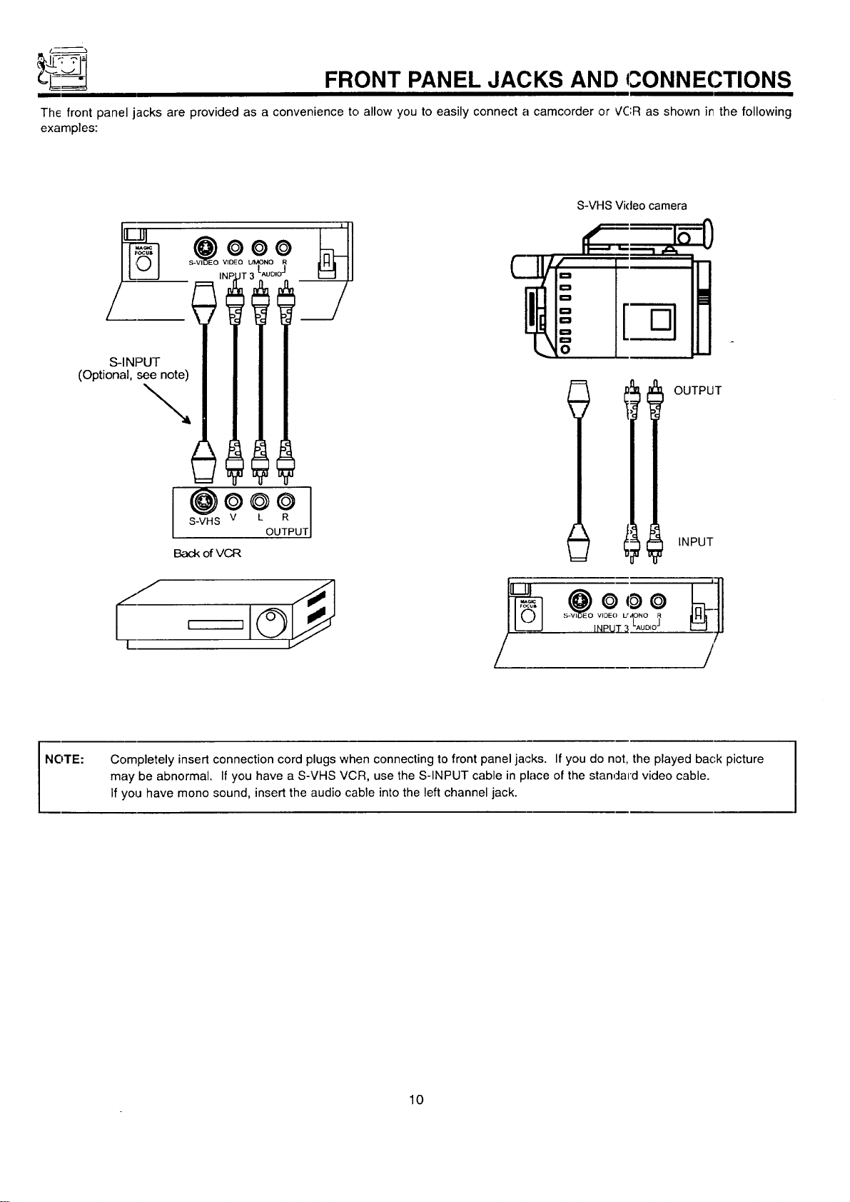
__ FRONT PANEL JACKS AND CONNEC.TIONS
The front panel jacks are provided as a convenience to allow you to easily connect a camcorder or VCR as shown it7the following
examples:
°
• i_ =°E° __
(Optional se__
I@o*o
S-VHS V L R
OUTPUT
Back ofVCR
S-VHS Video camera
J •
t ,-,
D
D
D
0
0
t
OUTPUT
INPUT
-7
NOTE:
Completely insert connection cord plugs when connecting to front panel jacks. If you do not, the played bac,k picture
may be abnormal• If you have a S-VHS VCR, use the S-INPUT cable in place of the standard video cable.
If you have mono sound, insert the audio cable into the left channel jack.
10
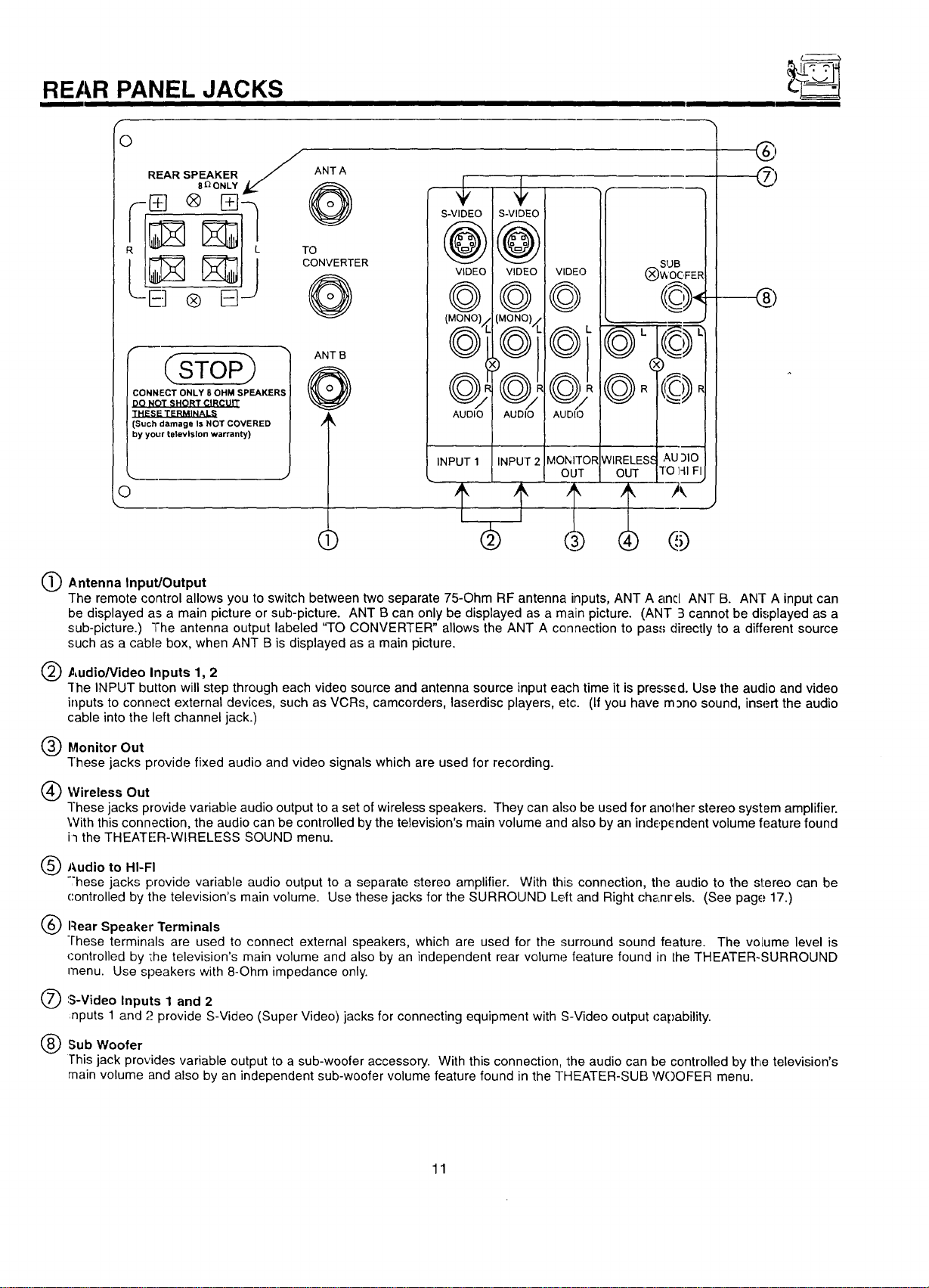
REAR PANEL JACKS
O
/
REAR SPEAKER / ANTA
® 15]J
CSTOP
CONNECT ONLY 8 OHM SPEAKERS
DO NOT SHORT CIRCUIT
THESE TERMINALS
(Such damage Is NOT COVERED
by yoL)r television warranty)
O
ANT B
> @
()
6"16°
©,©/,G
M'
(i
SUB
@=1@
1'-2'_-
® @
Antenna Input/Output
The remote control allows you to switch between two separate 75-Ohm RF antenna inputs, ANT A and ANT B. ANT A input can
be displayed as a main picture or sub-picture. ANT B can only be displayed as a main picture. (ANT 3 cannot be displayed as a
sub-picture.) "The antenna output labeled "TO CONVERTER" allows the ANT A connection to pass directly to a different source
such as a cable box, when ANT B is displayed as a main picture.
Audio/Video Inputs 1, 2
-[he INPUT button will step through each video source and antenna source input each time it is pressed. Use the audio and video
inputs to connect external devices, such as VCRs, camcorders, laserdisc players, etc. (If you have m_no sound, insert the audio
cable into the left channel jack.)
@Monitor Out
These jacks provide fixed audio and video signals which are used for recording.
Wireless Out
These jacks provide variable audio output to a set of wireless speakers. They can also be used for anolher stereo system amplifier.
With this connection, the audio can be controlled by the television's main volume and also by an indep_ ndent volume feature found
i'l the THEATER-WIRELESS SOUND menu.
@Audio to HI-FI
"'hese jacks provide variable audio output to a separate stereo amplifier. With this; connection, the audio to the stereo can be
controlled by the television's main volume. Use these jacks for the SURROUND Left and Right chanrels. (See page 17.)
Rear Speaker Terminals
These terminals are used to connect external speakers, which are used for the surround sound feature. The volume level is
(:ontrolled by ';he television's main volume and also by an independent rear volume feature found in the THEATER-SURROUND
menu. Use speakers with 8-Ohm impedance only.
'S-Video Inputs 1 and 2
nputs 1 and "._provide S-Video (Super Video) jacks for connecting equipment with S-Video output capability.
Sub Woofer
This jack provides variable output to a sub-woofer accessory. With this connection, the audio can be controlled by the television's
main volume and also by an independent sub-woofer volume feature found in the THEATER-SUB NOOFER menu.
11
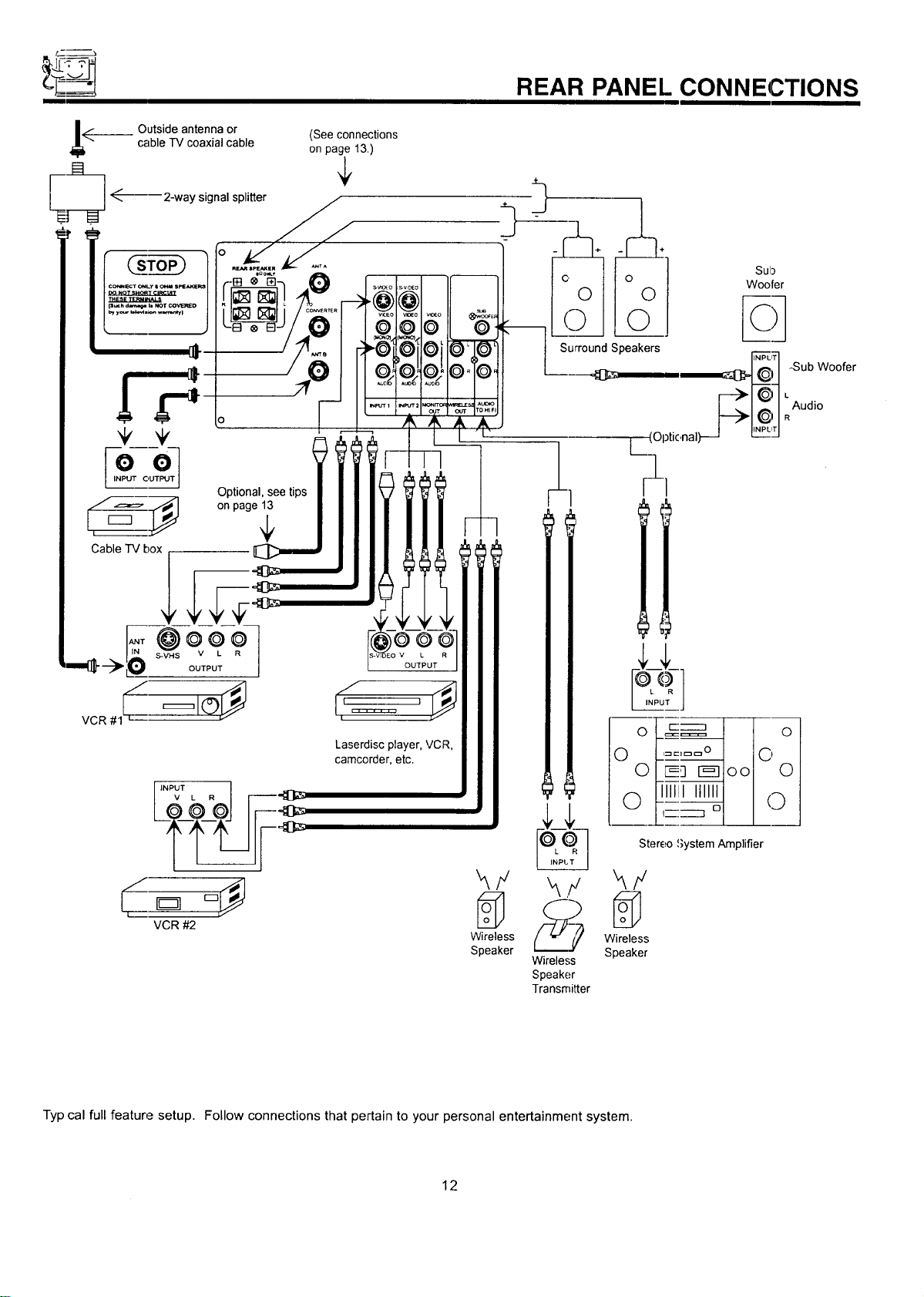
REAR PANEL CONNECTIONS
__ Outside antenna or (See connections
cable TV coaxial cable on page 13.)
_------ 2-way signal splitter
.
ooJ
INPUT OUTPUT
Optional, see tips
,_=_=- ::_ on page 1_
Cable TV box
Laserdisc player. VCR,
camcorder, etc.
VCR #2
Wireless Wireless
Speaker Speaker
Wireless
Speaker
Transmitter
!_1 Iol
'::_ °1 I I
Stereo System Amplifier
Typ cal full feature setup. Follow connections that pertain to your personal entertainment system.
12
REAR SPEAKER TERMINAL CONNECTIONS
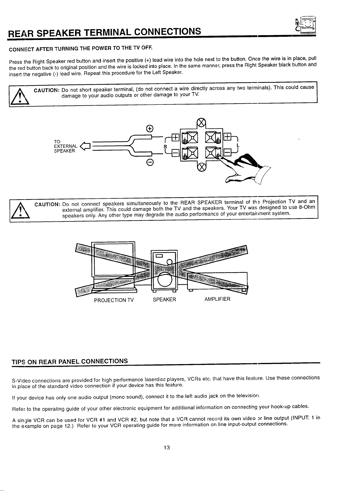
CONNI-'CT AFTER TURNING THE POWER TO THE TV OFF.
Press the Right Speaker red button and insert the positive (+) lead wire into the hole next to the button. Once the wire is in place, pull
the red button back to original position and the wire is locked into place. In the same manner, press the Right Speaker black button and
insert the negative (-) lead wire. Repeat this procedure for the Left Speaker.
l,#_e _, CAUTION: Do not short speaker terminal, (do not connect a wire directly across any two terminals). This could cause
damage to your audio outputs or other damage to your TV.
TO
EXTERNAL<_
SPEAKER
CAUTION: Do not connect speakers simultaneously to the REAR SPEAKER terminal of th_ Projection TV and an
external amplifier. This could damage both the TV and the speakers. Your TV was designed to use 8-Ohm
speakers only. Any other type may degrade the audio performance of your entertainment system.
I
PROJECTION TV SPEAKER AMPLIFIER
TIPS, ON REAR PANEL CONNECTIONS
S-Video connections are provided for high performance laserdisc players, VCRs etc. that have this feature. Use these connections
in place of the standard video connection if your device has this feature.
If your device has only one audio output (mono sound), connect it to the left audio jack on the television.
Refer to the operating guide of your other electronic equipment for additional information on connecting your hook-up cables.
A single VCR can be used for VCR #1 and VCR #2, but note that a VCR cannot record its own video or line output (INPUT: 1 in
the e:<ample on page 12.) Refer to your VCR operating guide for more information on line input-output connections.
13
-p____--
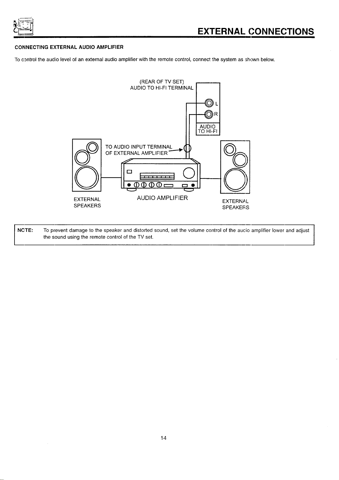
CONNECTING EXTERNAL AUDIO AMPLIFIER
To control the audio level of an external audio amplifier with the remote control, connect the system as shown below.
EXTERNAL CONNECTIONS
(REAR OF TV SET)
AUDIO TO HI-FI TERMINAL
TO AUDIO INPUT TERMINAL _ (
OF EXTERNAL AMPLIFIER '''-'_
----_ L
EXTERNAL AUDIO AMPLIFIER
EXTERNAL
SPEAKERS SPEAKERS
NCITE:
I
To prevent damage to the speaker and distorted sound, set the volume control of the aucio amplifier lower and adjust I
the sound using the remote control of the TV set.
I
14
CONNECTING EXTERNAL VIDEO SOURCES
The exacl arrangement: you use to connect the VCR, camcorder, and laserdisc player to your TV set is dependent on the model and
features c,feach component. Check the owner's manual of each component for the location of video and audic inputs and outputs.
The following connection diagrams are offered as suggestions. However, you may need to modify them to accommodate your particular
assortment of components and features. For best performance, video and audio cables should be made trorn coaxial shielded wire.
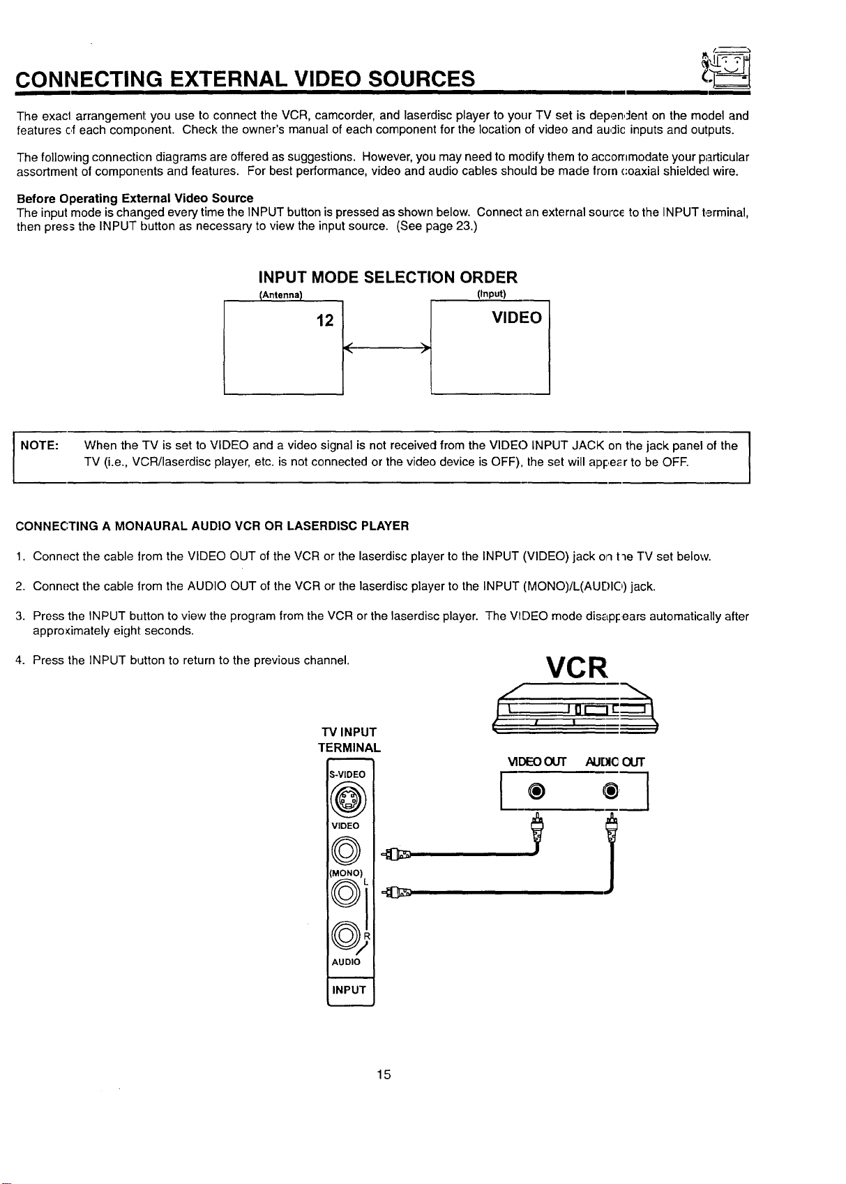
Before Operating External Video Source
The input mode is changed every time the INPUT button ispressed as shown below. Connect an external sourc_ to the INPUT terminal,
then press the INPUT button as necessary to view the input source. (See page 23.)
INPUT MODE SELECTION ORDER
I NOTE:
I
When the TV is set to VIDEO and a video signal is not received from the VlDEC) INPUT JACK on the jack panel of the
TV (i.e., VCR/laserdisc player, etc. is not connected or the video device is OFF), the set will apl:,e_r to be OFF.
CONNECTING A MONAURAL AUDIO VCR OR LASERDISC PLAYER
1. Connect the cable lrom the VIDEO OUT of the VCR or the laserdisc player to the INPUT (VIDEO) jack on t'le TV set below.
2. Connect the cable lrom the AUDIO OUT of the VCR or the laserdisc player to the INPUT (MONO)/L(AUF)IO) jack.
3. Press the INPUT button to view the program from the VCR or the laserdisc player. The V_I)EO mode dis_LpFears automatically after
approximately eight seconds.
4. Press the INPUT button to return to the previous channel.
TV INPUT
TERMINAL
S-VIDEC
((r,_.._,
VIDEO
(MONO)
\,,__J j,,
((r-_'_
\\_JW
AUDIO
I
INPU1
VCR
l ,
[
VIDEOOUT AUDIC OUT
® ® ]
15
CONNECTING EXTERNAL VIDEO SOURCES
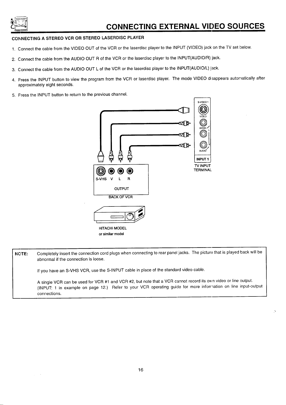
COhINECTING A STEREO VCR OR STEREO LASERDISC PLAYER
1. Connect the cable from the VIDEO OUT of the VCR or the laserdisc player to the INPUT (VIDEO) jack on the TV set below.
2. Connect the cable from the AUDIO OUT R of the VCR or the laserdisc player to the INPUT(AUDIO/R) jack.
3. Connect the cable from the AUDIO OUT L of the VCR or the laserdisc player to the INPUT(AUDIO/L) jack.
4. Press the INPUT button to view the program from the VCR or laserdisc player. The mode VIDEO disappears automatically after
approximately eight seconds.
5. Fress the INPUT button to return to the previous channel.
@®®®
S-VHS V L R
OUTPUT
S-VIDEO 1
(@)
VIDEO
f...-.-_%
fuo_1 •
(_
AUL)IU
INPUT I
TV INPUT
TERMINAL
BACK OFVCR
S I
I
HITACHI MODEL
or similar model
NOTE: Completely insert the connection cord plugs when connecting to rear panel jacks. The picture that is played back will be
abnormal if the connection is loose.
If you have an S-VHS VCR, use the S-INPUT cable in place of the standard video cable.
A single VCR can be used for VCR #1 and VCR #2, but note that a VCR cannot record its own video or line output.
(INPUT: 1 in example on page 12.) Refer to your VCR operating guide for more inforr_ation on line input-output
connections.
16
AUDIO SYSTEM SETUP
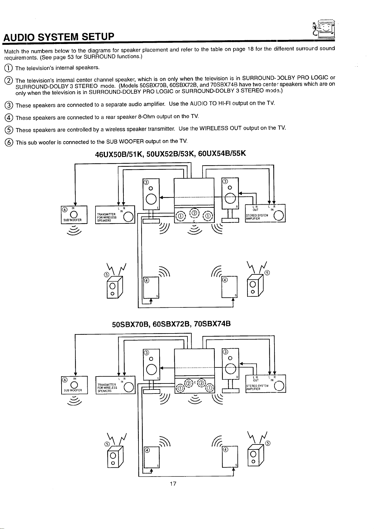
Match the numbers below to the diagrams for speaker placement and refer to the table on page 18 for the different surrour,d sound
requirem,_nts. (See page 53 for SURROUND functions.)
O The television's internal speakers.
(_) The television's internal center channel speaker, which is on only when the television is in SURROUND-9OLBY PRO LOGIC or
SURROUND-DOL.BY 3 STEREO mode, (Models 50SBX70B, 60SBX72B, and 70SBX740 have two center speakers which are on
only when the television is in SURROUND-DOLBY PRO LOGIC or SURROUND-DOLBY 3 STEREO mod,_.)
Q These speakers are connected to a separate audio amplifier. Use the AUDIO TO HI-FI output on the TV.
(_) These speakers are connected to a rear speaker 8-Ohm output on the TV.
Q The,';e speakers are controlled by a wireless speaker transmitter. Use the WIRELESS C)UT output on the TV.
(_ This sub woofer is connected to the SUB WOOFER output on the TV.
46UX50B/51K, 50UX52B/53K, 60UX54B/55K
50SBX70B, 60SBX72B, 70SBX74B
]!
FORWIRELESS
$PEA_ERS
ill11
17
AUDIO SYSTEM SETUP
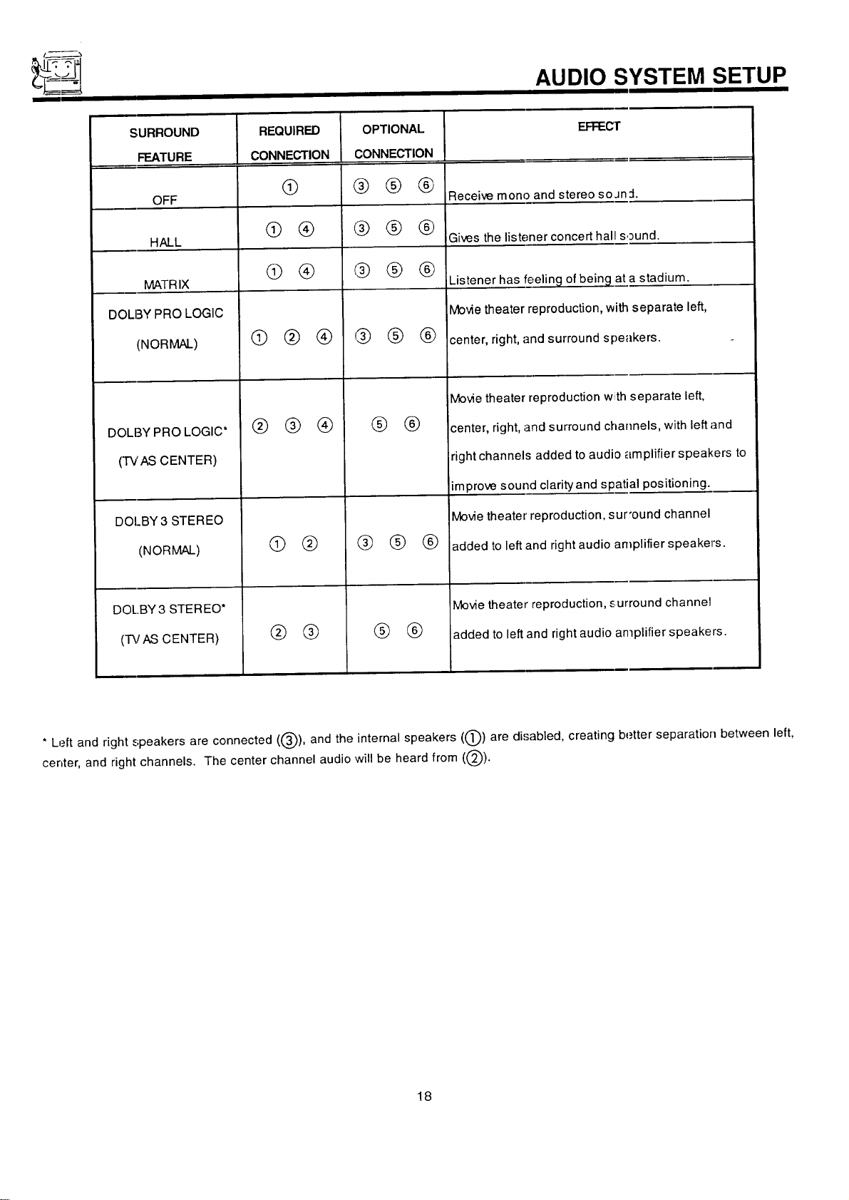
SURROUND EFFEC'I"
FEATURE
OFF Receive mono and stereo so Jn :1.
HALL Gives the listener concert hal sound.
MATRIX
DOLBY PRO LOGIC
(NORMAL)
DOLBY PRO LOGIC*
(TVAS CENTER)
DOI_BY3 STEREO
(NORMAL)
DOL.BY 3 STEREO*
(-I'_fAS CENTER)
REQUIRED
CONNECTION
@
@ ®
@ @
@@®
@ @®
® @
® ®
OPTIONAL
CONNECTION
@@®
@@ @
@@@
@@®
® ®
@ @ ®
® ®
Listener has feeling of being at a stadium.
Movie theater reproduction, _ separate left,
center, right, and surround s :_eakers.
Movie theater reproduction w separate left,
center, right, and surround channels, with left and
right channels added to audi plifier speakers to
improve sound clarityand spatial positioning.
Movie theater reproduction, sur'ound channel
added to left and right audio amplifier speaker's.
Movie theater reproduction, surround channel
added to left and right audio amplifier speakers.
* Left and right speakers are connected ((_), and the internal speakers ((_)) are disabled, creating better separation between left,
center, and right channels. The center channel audio will be heard from ((_).
18
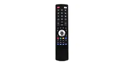
THE GENIUS REMOTE CONTROL (CLU-612MP)
In additi3n to controlling all the functions on your HITACHI
Projection TV, the remote control is designed to operate different
types of VCRs, CATV (cable TV)/satellite converters, and audio
equipment with one touch. Basic operation keys are grouped
together in one area. All other controls are separated from them
and arranged in MULrI-PAGE sections, with a display that can
be switched to cover any of the three pages. Functions are
arrangecl and properly categorized into windows, making opera-
tion simple when multiple functions are to be controlled.
To operate your TV, slide the MULTI-PAGE select switch on the
side of the remote to TV/CABLE/DSS mode. Press the TV button
and the remote will now control your television.
To operate your cable box, slide the MULTI-PAGE select switch
on the side of the remote to TV/CABLE/DSS mode. Press the
CABLE button and the remote will now control your cable box.
(See page 28 for instructions on how to program the remote to
control your cable box.)
To operate your satellite box, slide the MULTI-PAGE select
switch on the side of the remote to TV/CABLE/DSS mode. Press
the DSS button and the remote will now control your satellite box.
(See page 28 for instructions on how to program the remote to
control your satellite box.)
Tooperate your VCR, slide the MULTI-PAGE select switch on the
side of the remote to VCR mode. The remote will now control
your VC :L (See page 27 for instructions on how to program the
remote t3 control your VCR.)
To oper_Lteyour audio equipment, slide the MULTI-PAGE select
switch on the side oil the remote to AUDIO mode. Press the
button which corresponds to the component you would like to
control (,_.MP,CD, TAPE). The remote will now control your audio
equipment. (See page 29 for instructions on how to program the
remote to control your audio equipment.)
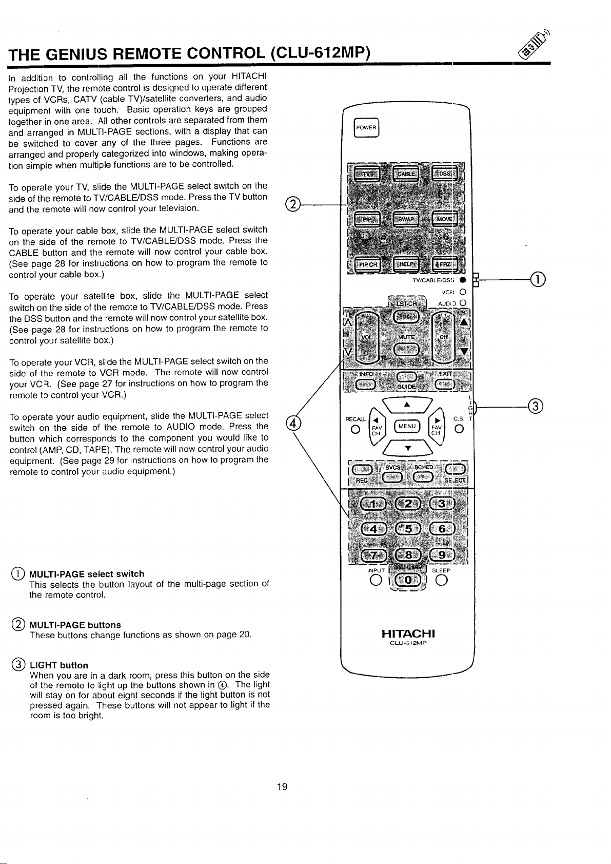
O MULTI-PAGE select switch
Thi.'; selects the button layout of the multi-page section of
the remote control.
Q MULTI-PAGE buttons
These buttons change functions as shown on page 20.
Q LIGHT button
When you are in a dark room, press this button on the side
of t,ne remote to bightup the buttons shown in (_). The light
will stay on for about eight seconds if the light button is not
pressed again. These buttons will not appear to light if the
room is too bright.
®
TV/CABLE_DS,(; •
INPU_F SLE EP
C) C)
H ITAG H I
CLU_I 21VIP
J
®
®
19
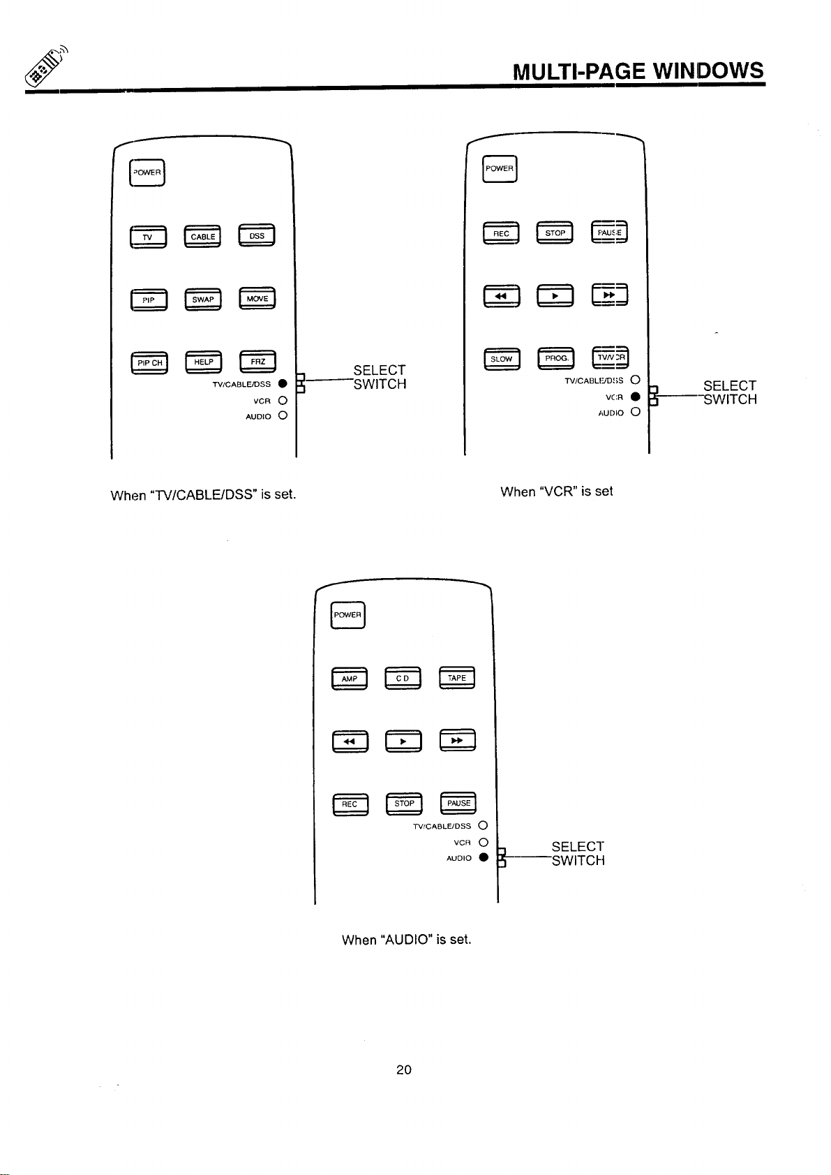
MULTI-PAGE WINDOWS
TV/CABLE/DSS •
VCR O
AUDIO O
SELECT
SWITCH
TV/CABLIUD ,{;S 0
VCR •
AUDIO 0
SELECT
SWITCH
When "TV/CABLE/DSS" is set.
When "VCR" is set
TV/CABLFJDSS O
VCR O
AUDIO •
SELECT
SWITCH
When "AUDIO" is set.
2O
HOW TO USE THE GENIUS REMOTE TO CONTROL YOUR TV
®
@
®
%
TV/CABLF_JDSS •
INFO O EXIT
CZ) Gu,oECZ)
L
I
c
C.S. T
0
SVCS SCHED SELC_ECT
(Z) CZD
INPUT
0
HITACHI
CLLJ-61_P
@
®
--®
J
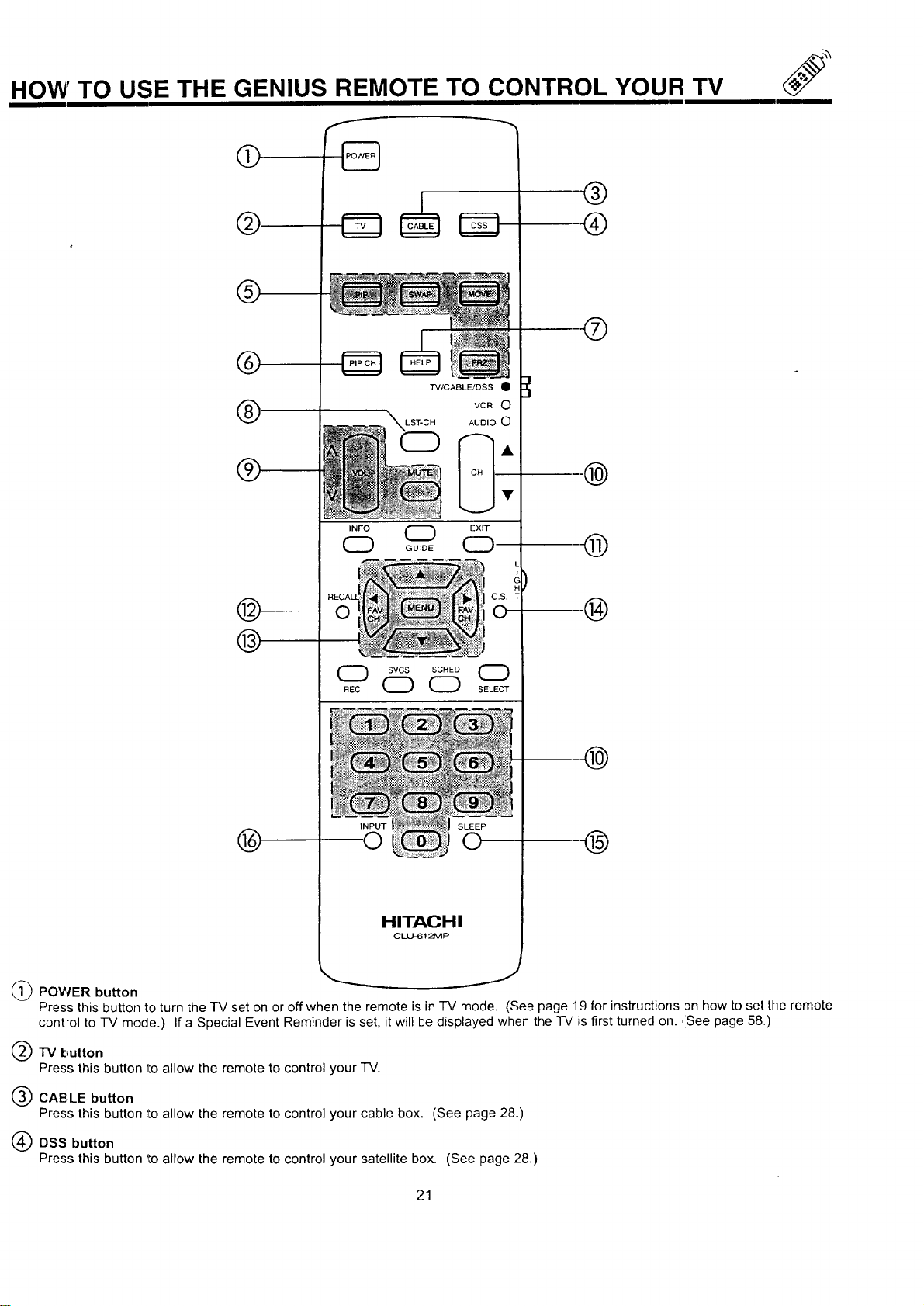
@POWER button
Press this button to turn the "IV set on or off when the remote is in -IV mode. (See page 19 for instructions an how to set the remote
cont'ol to TV mode.) If a Special Event Reminder is set, it will be displayed when the "rv is first turned on. ISee page 58.)
TV button
Press this button 1:oallow the remote to control your TV.
CAE',LE button
Press this button to allow the remote to control your cable box. (See page 28.)
DSS button
Press this button to allow the remote to control your satellite box. (See page 28.)
21
HOW TO USE THE GENIUS REMOTE TO CONTROL YOUR TV
I I I
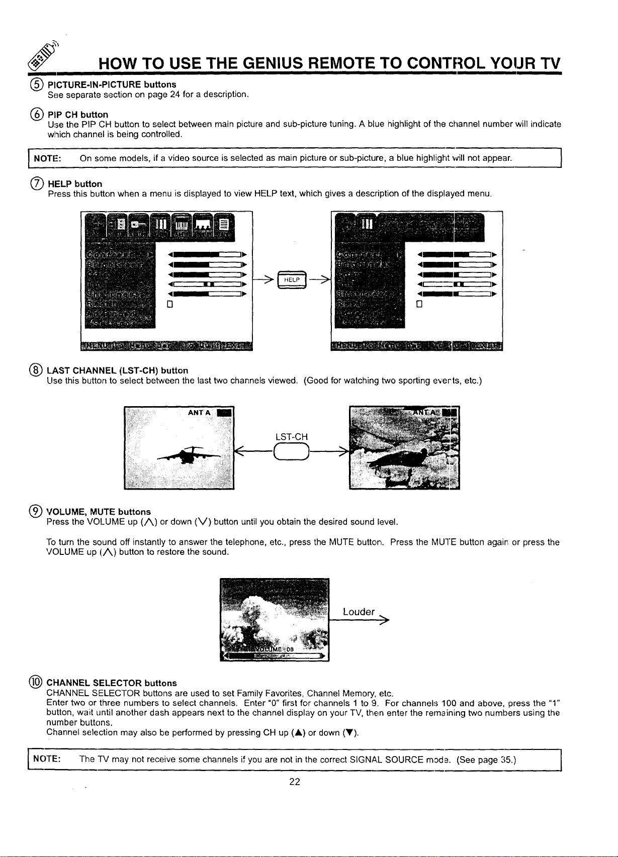
PICTURE-IN-PICTURE buttons
See separate section on page 24 for a description.
(_) PIP CH button
Use the PIP CH button to select between main picture and sub-picture tuning. A blue highlight of the channel number will indicate
which channel is being controlled.
I NOTE': On some models, if a video source is selected as main picture or sub-picture, a blue highlight will not
appear.
HELP button
Press this button when a menu is displayed to view HELP text, which gives a description of the displayed menu.
LAST CHANNEL (LST-CH) button
Llse this button to select between the last two channels viewed. (Good for watching two sporting everts, etc.)
LST-CH
C
@VOLUME, MUTE buttons
Press the VOLUME up (/_) or down (V) button until you obtain the desired sound level.
Fo turn the sound off instantly to answer the telephone, etc., press the MUTE button. Press the MUTE button agair or press the
VOLUME up (/_) button to restore the sound.
Louder
>
CHANNEL SELECTOR buttons
CHANNEL SELECTOR buttons are used to set Family Favorites, Channel Memory, etc.
Enter two or three numbers to select channels. Enter "0" first for channels 1 to 9. For channels 100 and above, press the "1"
button, wait until another dash appears next to the channel display on your TV, then enter the remaining two numbers using the
number buttons.
Channel selection may also be performed by pressing CH up (A) or down (llF).
NOTE: "IV may not receive some channels if you are not in the correct SIGNAL SOURCE mode. (See page 35.)
The
22
TO USE THE REMOTE TO CONTROL YOUR TV
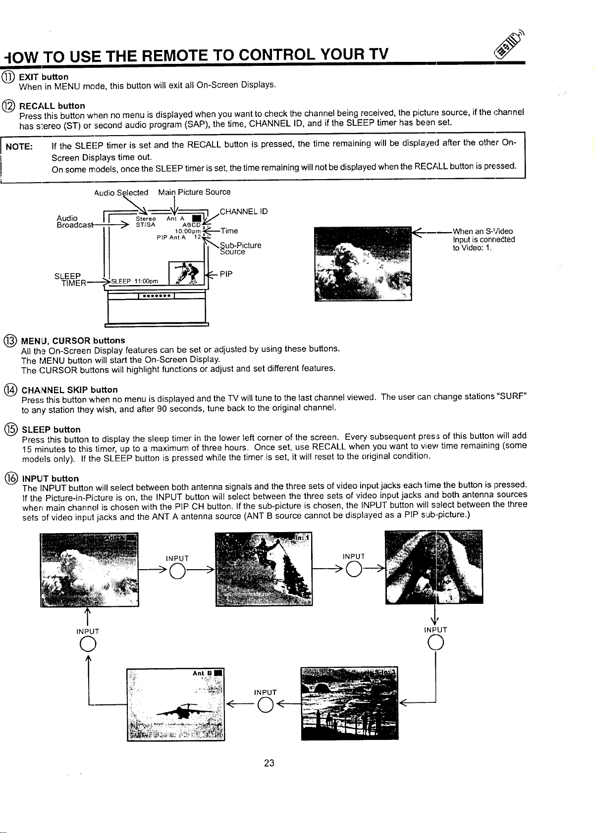
EXIT button
When in MENU mode, this button will exit all On-Screen Displays.
(_ RECALL button
Press this button when no menu is displayed when you want to check the channel being received, the picture source, if the channel
has s'Lereo (ST) or second audio program (SAP), the time, CHANNEL ID, and if the SLEEP timer has be,_n set.
If the SLEE'P timer is set and the RECALL button is pressed, the time remaining will be displa'./ed after the other On-
Screen Displays time out.
On some models, once the SLEEP timer is set, the time remaining will not be displayed when the REC,_LL button is pressed.
I NOTE:
i
!
i
.AudioSelected Main Picture Source
Audio _ Stereo Ant A [] 3.r_,ICHANNEL
ID
_roaacast--- _ ST/SA ABCD
10:O0pm _----Time
PIP Ant A 12
_ub-Picture
bource
SLEEP I ,"'_' "--PIP
TIMER m- SLEEP 11:0Oprn
I ""°°'° I
|.
Q MENLI, CURSOR buttons
All th,_ On-Screen Display features can be set or adjusted by using these buttons.
The MENU button will start the On-Screen Display.
The CURSOR buttons will highlight functions or adjust and set different features.
(_ CHAI_INEL SKIP button
hen an S-Video
Input is connected
to Video: I.
Pres.';this button when no menu is displayed and the -IV will tune to the last channel viewed. The user can change stations "SURF"
to any station they wish, and after 90 seconds, tune back to the original channel.
O SLEE'P button
Pres=_this button to display the sleep timer in the lower left corner of the screen. Every subsequent press of this button will add
15 minutes to this timer, up to a maximum of three hours. Once set, use RECALL when you want to view time remaining (some
models only)• If the SLEEP button is pressed while the timer is set, it will reset to the original condition.
Q INPIJIT button
The INPUT button will select between both antenna signals and the three sets of video inputjacks each time the button is pressed.
If the Picture-in-Picture is on, the INPUT button will select between the three sets of video input jacks ancJboth antenna sources
when main channel is chosen with the PIP CH button. If the sub-picture is chosen, the INPUT button will s_lect between the three
sets of video input jacks and the ANT A antenna source (ANT B source cannot be displayed as a PIP sijb..picture.)
INPUT
INPUT
INPUT
©
_ _ _ ;_ _L_
INPUT
,t"
INPUT
0
23
PICTURE-IN-PICTURE (PIP)
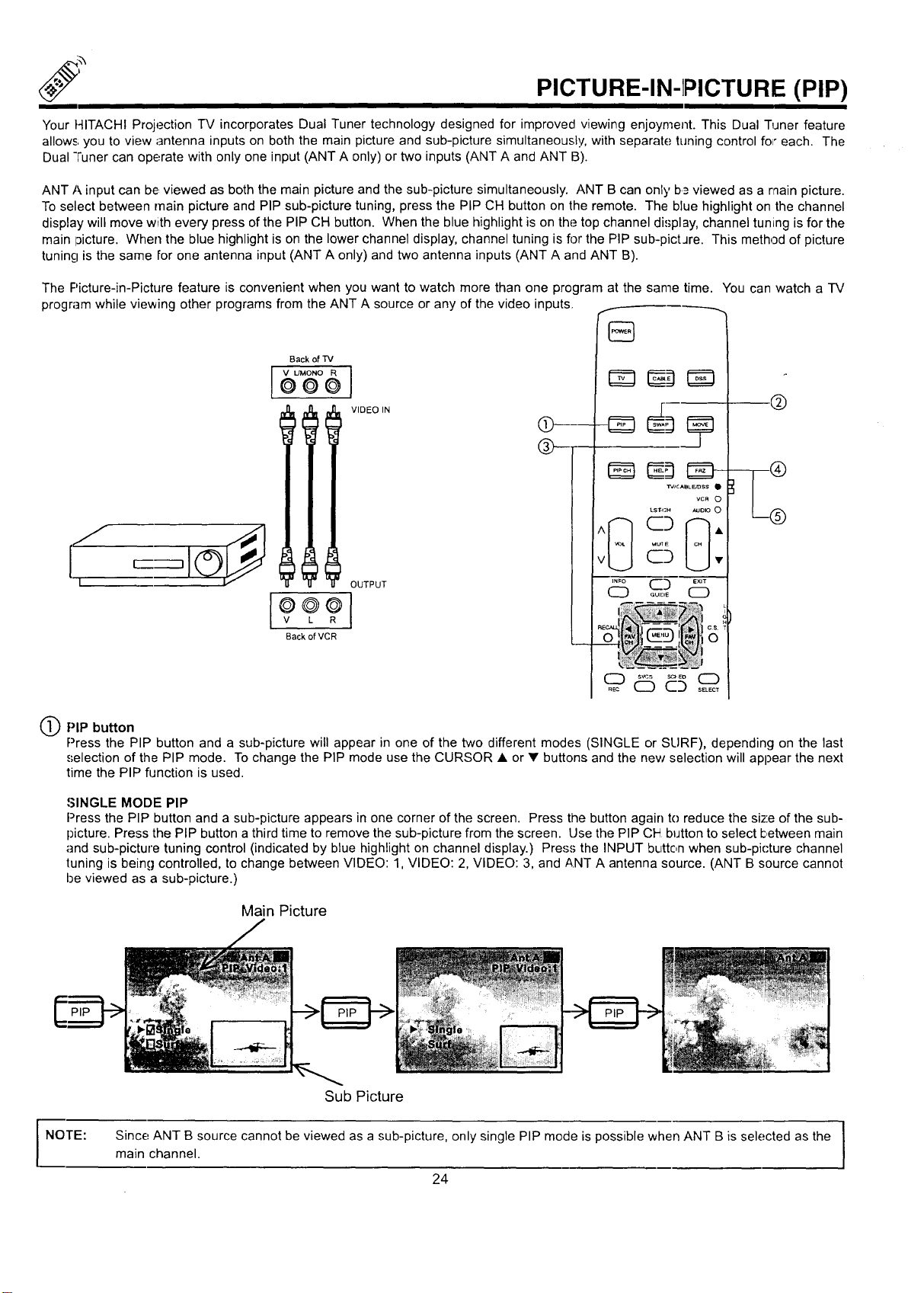
Your t41TACHI Projection TV incorporates Dual Tuner technology designed for improved viewing enjoyment. This Dual Tuner feature
allows you to view antenna inputs on both the main picture and sub-picture simultaneoust!t, with separate tuning control fo="each. The
Dual "Funercan operate with only one input (ANT A only) or two inputs (ANT A and ANT B).
ANT A input can be viewed as both the main picture and the sub-picture simultaneously. ANT B can only b.=viewed as a main picture.
To select between main picture and PIP sub-picture tuning, press the PIP CH button on the remote. The blue highlight on the channel
display will move with every press of the PIP CH button. When the blue highlight is on the top channel di.';play, channel tuning is for the
main 13icture. When the blue highlight is on the lower channel display, channel tuning is fl3rthe PIP sub-pictJre. This method of picture
tuning is the same for one antenna input (ANT A only) and two antenna inputs (ANT A and ANT B).
The F'icture-in-Picture feature is convenient when you want to watch more than one program at the same time. You can watch a TV
program while viewing other programs from the ANT A source or any of the video inputs. .--
I
Back of TV
VIDEO IN
OUTPUT
I÷÷91
Back of VCR
[]
/vJc AeL E,'BSS Q
VCR O
LST-,;H _JO_ O
C3 ,,
d5
@
QPIP button
Press the PIP button and a sub-picture will appear in one of the two different modes (SINGLE or SURF), depending on the last
.,;election of the PIP mode. To change the PIP mode use the CURSOR • or • buttons and the new selection will appear the next
time the PIP function is used.
•'_INGLE MODE PIP
Press the PIP button and a sub-picture appears in one corner of the screen. Press the button again to reduce the size of the sub-
picture. Press the PIP button a third time to remove the sub-picture from the screen. Use the PIP CI4 button to select I:,etween main
and sub-picture tuning control (indicated by blue highlight on channel display.) Press the INPUT button when sub-pi('ture channel
tuning is being controlled, to change between VIDEO: 1, VIDEO: 2, VIDEO: 3, and ANT A antenna source. (ANT B source cannot
be viewed as a sub-picture.)
Main Picture
NOTE:
Sub Picture
Since ANT B source cannot be viewed as a sub-picture, only single PIP mode is possible when ANT B is selected as the
main channel.
24
PICTURE-IN-PICTURE (PIP)
PICTURE-IN-PICTURE" CONT,
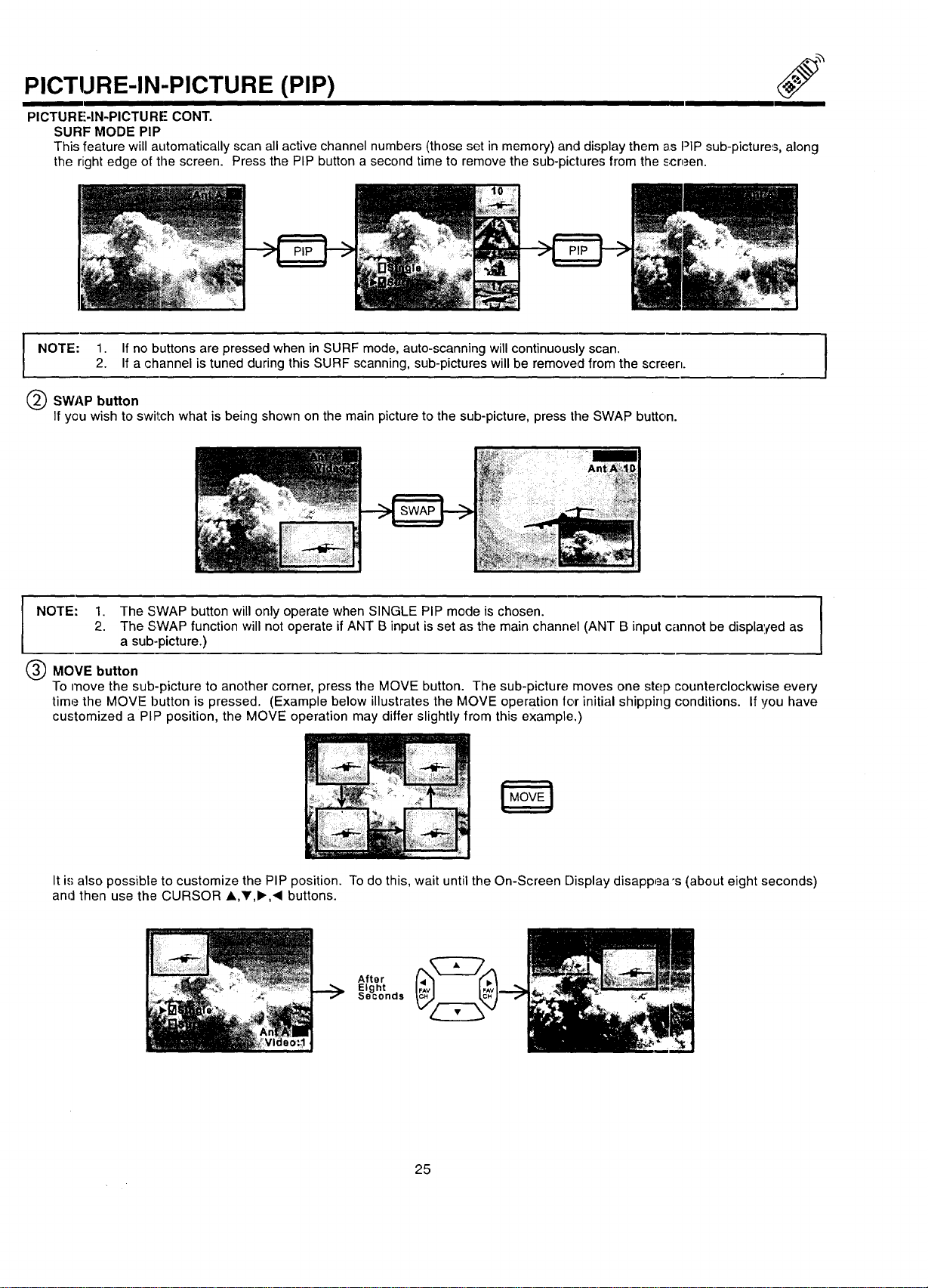
SURF MODE PIP
This feature will automatically scan all active channel numbers (those set in memory) and display them as PiP sub-pictures, along
the right edge of the screen. Press the PIP button a second time to remove the sub-pictures from the screen.
I OTE: 1. If no buttons are pressed when in SURF mode, auto-scanning will continuously scan.2. If a channel is tuned during this SURF scanning, sub-pictures will be removed from the screen.
@SWAP button
If you wish to switch what is being shown on the main picture to the sub-picture, press the SWAP button.
NOTE: 1. The SWAP button will only operate when SINGLE PIP mode is chosen.
2. The SWAP function will not operate if ANT B input is set as the main channel (ANT B input cannot be displayed as
a sub-picture.)
MOVE button
To move the sub-picture to another corner, press the MOVE button. The sub-picture moves one step counterclockwise every
time the MOVE button is pressed. (Example below illustrates the MOVE operation tor initial shipping conditions. If you have
customized a PIP position, the MOVE operation may differ slightly from this example.)
It i,,,"also possible to customize the PIP position. To do this, wait until the On-Screen Display disappea "s (about eight seconds)
and then use the CURSOR ,,V,_.,< buttons.
After
Eight .
Seconas
25
PICTURE-IN-PICTURE (PIP)
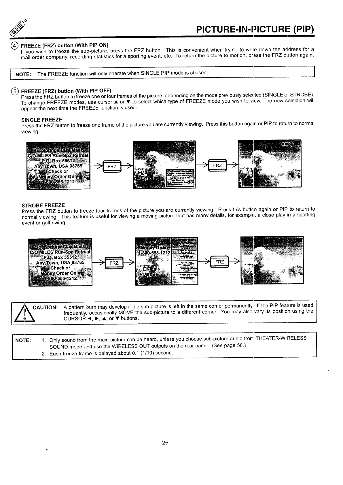
FREEZE (FRZ) button (With PIP ON)
If you wish to freeze the sub-picture, press the FRZ button. This is convenient when trying to wrile down the address for a
mail order company, recording statistics for a sporting event, etc. To return the picture to motion, press the FRZ button again.
NOTE: The FREEZE function will only operate when SINGLE PIP mode is chosen.
(_) FREEZE (FRZ) button (With PIP OFF)
Press the FRZ button to freeze one or four frames ofthe picture, depending on the mode previously selected (SINGLE or STROBE).
"5_change FRI--EZE modes, use cursor • or • to select which type of FREEZE mode you wish tc view. The new selection will
appear the nex't time the FREEZE function is used.
SINGLE FREEZE
Press the FRZ button to freeze one frame of the picture you are currently viewing. Press this button again or PIP to return to normal
viewing.
STROBE FREEZE
Press the FRZ button to freeze four frames of the picture you are currently viewing. Press this b_ttcn again or PIP to return to
normal viewing. This feature is useful for viewing a moving picture that has many details, for example, a close play in a sporting
event or golf swing.
I /kCAUTION: A pattern burn may develop if the sub-picture is left in the same comer permanently. If the PIP fealure is used I
u
frequently, occasionally MOVE the sub-picture to a different corner. You may also vary its position using the
(
/ qD \ CURSOR "q, I_, •, or • buttons.
NOTRE: 1. Only sound from the main picture can be heard, unless you choose sub-picture audio frorr THEATER-WIRELESS
SOUND mode and use the WIRELESS OUT outputs on the rear panel. (,'Seepage 56.)
2. Each freeze frame is delayed about 0.1 (1/10) second.
26
USING THE REMOTE TO CONTROL VCR FUNCTIONS
Operating the precoded function for your VCR.
This remote is designed to operate different types of VCRs.
VCR. (Refer to page 30.)
1. Set the MULTI-PAGE select switch to VCR,
2.
3.
4.
5.
You must first program the remote to match the remote system of your
Turn ON your VCFt.
Aim the remote control at the front of your VCR.
Hold down the PROG button on the remote, enter the two digit preset code that matches your VCR as shown in page :30. The
remote will turn off your VCR when the correct two digit preset code is entered. When this occurs, the remote control is pro-
gran'tmed for your VCR. If the VCR does not turn off after five seconds, try a different two digit preset code.
The remote will now control your VCR.
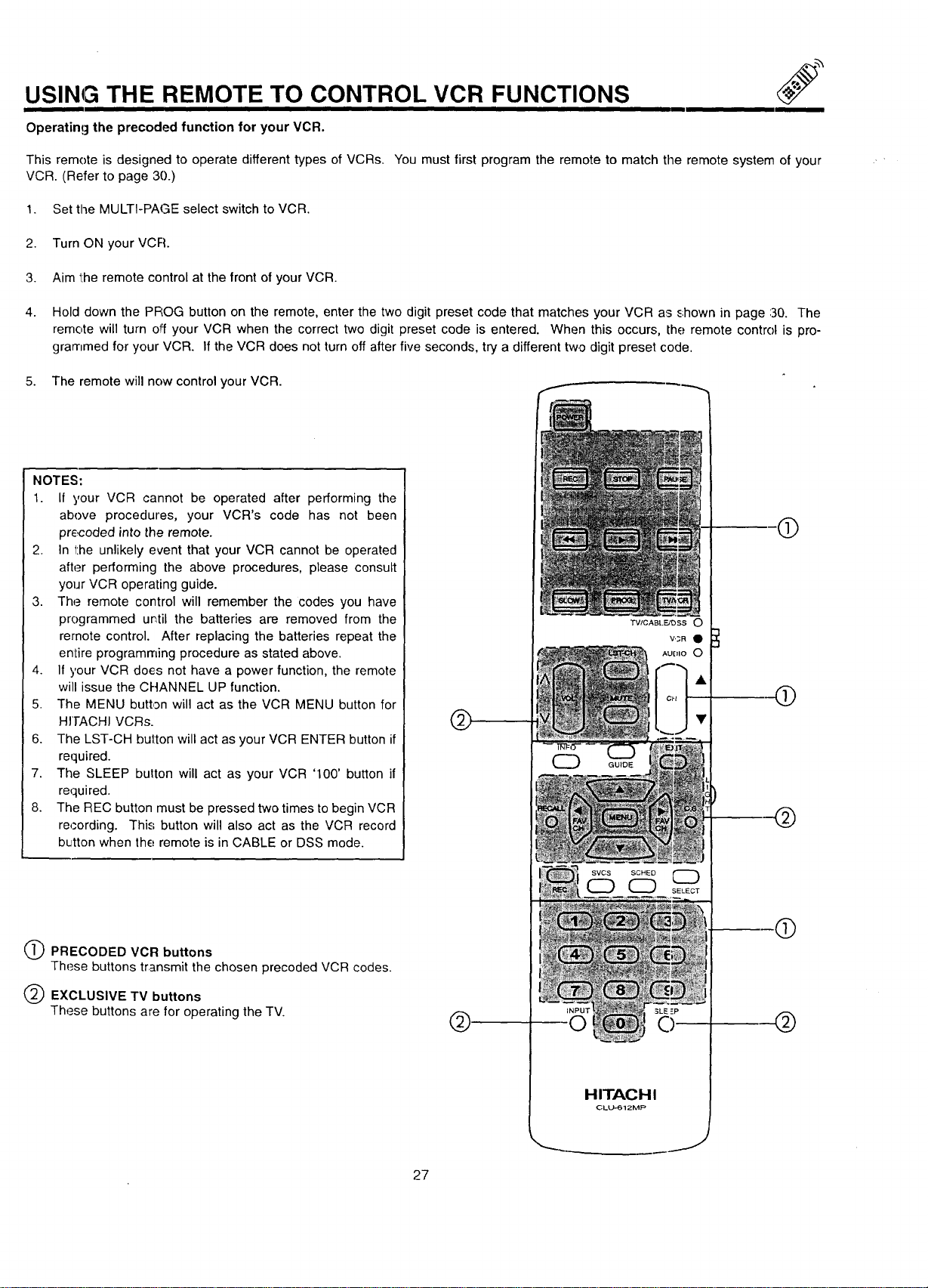
NOTES:
1. If your VCR cannot be operated after performing the
above procedures, your VCR's code has not been
pr_<:oded into the remote.
2. In the unlikely event that your VCR cannot be operated
after performing the above procedures, please consult
your VCR operating guide.
3. The remote control will remember the codes you have
programmed until the batteries are removed from the
remote control. After replacing the batteries repeat the
entire programming procedure as stated above.
4. If your VCR does not have a power function, the remote
will issue the CHANNEL UP function.
5. The MENU button will act as the VCR MENU button for
HrTACHI VCRs.
6. The LST-CH button will act as your VCR ENTER button if
required.
7. The SLEEP button will act as your VCR '100' button if
required.
8. The REC button must be pressed two times to begin VCR
recording. This button will also act as the VCR record
button when the remote is in CABLE or DSS mode.
PRECODED VCR buttons
These buttons transmit the chosen preceded VCR codes.
EXCLUSIVE TV buttons
These buttons are for operating the TV.
AUDIO O
SVCS SCHED
HITACHI
OLL_612MP
J
®
Q
@
®
@
27
USING THE REMOTE TO CONTROL
CABLE BOX/SATELLITE FUNCTIONS
Operating the precoded function for your cable/satellite box.
This remote is designed to operate different types of cable boxes and satellite systems. You must first progr_Lmthe remote to match the
remote system in your cable/satellite box. (Refer to page 30.)
1. Set the MULTI-PAGE select switch to TV/CABLE/DSS.
2. -['urn ON your cable/satellite box.
3. Press the CABLE button on the remote to switch to CABLE mode, or the DSS button to switch to DRS mode.
4. Aim the remote control at the front of your cable/satellite box.
3.
Hold down the. CABLE/DSS button on the remote, enter the two digit preset code that matched your cable/satellite box as shown
on page 30. -[he remote will turn off your cable/satellite box when the correct two digit preset code is entered. When this occurs,
the remote control is programmed for your cable/satellite box. If the cable/satellite box does not turn off after five ,seconds, try
another two digit preset code.
4. "]'he remote will now control your cable/satellite box,
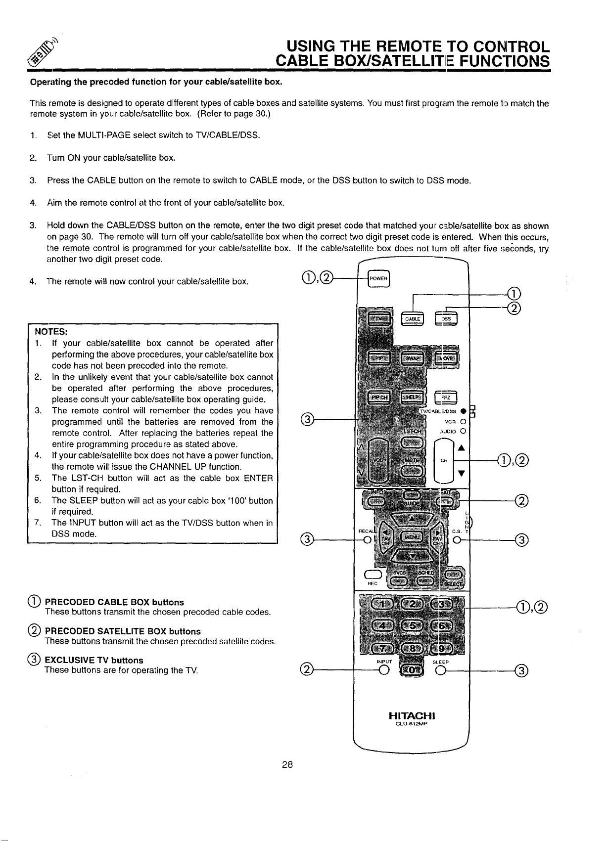
NOI"ES:
1. If your cable/satellite box cannot be operated after
performing the above procedures, your cable/satellite box
code has not been precoded into the remote.
2. In the unlikely event that your cable/satellite box cannot
be operated after performing the above procedures,
please consult your cable/satellite box operating guide.
3, The remote control will remember the codes you have
programmed until the batteries are removed from the
remote control. After replacing the batteries repeat the
entire programming procedure as stated above.
4. If your cable/satellite box does not have a power function,
the remote will issue the CHANNEL UP function.
5. The LST-CF-I button will act as the cable box ENTER
button if required.
6. The SLEEP button will act as your cable box '100' button
if required.
7. The INPUT button will act as the TV/DSS button when in
DSS mode.
O PRECODED CABLE BOX buttons
These buttons transmit the chosen precoded cable codes.
@
Q PRECODED SATELLITE BOX buttons
These buttons transmit the chosen precoded satellite codes.
EXCLUSIVE TV buttons
These buttons are for operating the TV.
I D,@
@
®
-®,@
®
28
J
JSING THE REMOTE TO CONTROL
AUDI() EQUIPMENT FUNCTIONS
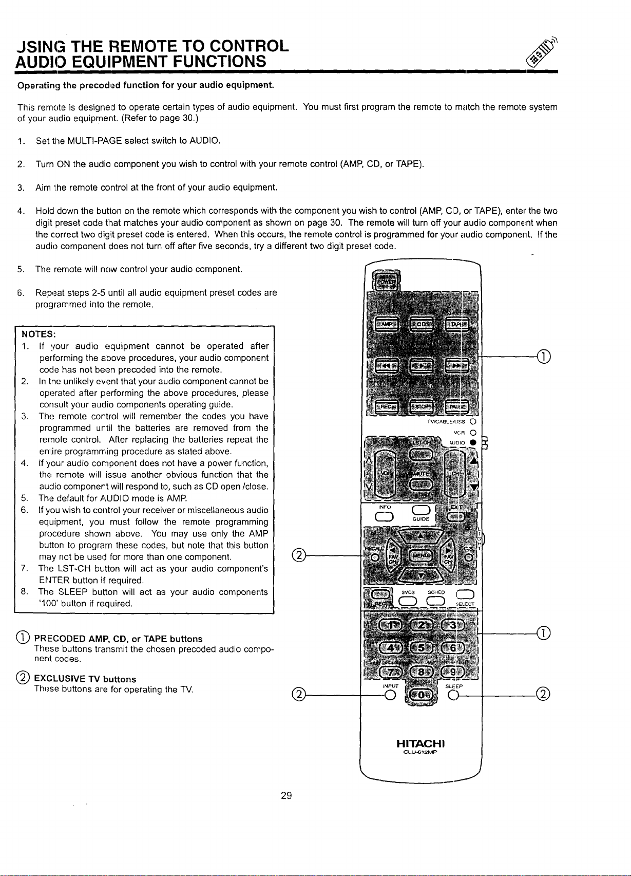
Operating the precoded function for your audio equipment.
This remote is designed to operate certain types of audio equipment. You must first program the remote to match the remote system
of your audio equipment. (Refer to page 30.)
1. Set the MULTI-PAGE select switch to AUDIO.
2. Turn ON the audio component you wish to control with your remote control (AMP, CD, or TAPE).
3. Aim the remote control at the front of your audio equipment.
4.
Hold down the button on the remote which corresponds with the component you wish to control (AMP, CO, or TAPE), enter the two
digit preset code that matches your audio component as shown on page 30. The remote will turn off your audio component when
the correct two digit preset code is entered. When this occurs, the remote control is programmed for your audio component. If the
audio component does not turn off after five seconds, try a different two digit preset code.
5. The remote will now control your audio component.
6. Repeat steps 2-5 until all audio equipment preset codes are
programmed into the remote.
NOTES:
1. If !,,our
audio equipment cannot be operated after
performing the aoove procedures, your audio component
code has not been precoded into the remote.
2. In the unlikely event that your audio component cannot be
operated after performing the above procedures, please
consult your audio components operating guide.
3. The remote control will remember the codes you have
programmed until the batteries are removed from the
remote control. After replacing the batteries repeat the
entire programrring procedure as stated above.
4. Ifyour audio component does not have a power function,
the remote will issue another obvious function that the
audio componer:t will respond to, such as CD open/close.
5. Th,a default for AUDIO mode is AMP.
6. If you wish to control your receiver or miscellaneous audio
equipment, you must follow the remote programming
procedure shown above. You may use only the AMP
button to program these codes, but note that this button
may not be used for more than one component,
7. The LST-CH button will act as your audio component's
ENTER button if required.
8. The SLEEP button will act as your audio components
'100' button if required.
Q PRECODED AMP, CD, or TAPE buttons
These buttons transmit the chosen precoded audio compo-
nent codes.
EXCLUSIVE TV buttons
These buttons are for operating the -IV.
TV/CABL E/OSS O
VC:R O
HITACHI
CLU-612MP
@
@
.@
J
29
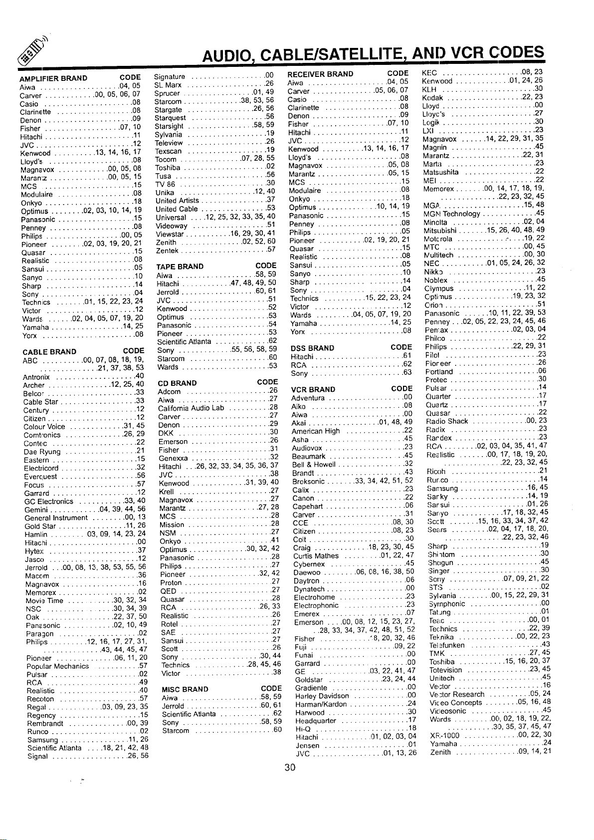
AMPLIFIER BRAND CODE
Aiwa ................... 04, 05
Carver ............ 00, 05, 06, 07
Casio ..................... 08
Clannette .................. 08
Denon ..................... 09
Fisher .................. 07, 10
Hitachi ..................... 11
JVC ....................... 12
Kenwcod .......... 13, 14, 16, 17
Lloyd'_ ..................... 08
Magnavox ............ 00, 05, 08
Maran':z .............. 00, 05, 15
MCS ...................... 15
Modulaire .................. 08
Onkyo ..................... 18
Qptimus ........ 02, 03, 10, 14, 19
Panasonic .................. 15
Penney .................... 08
Philips .................. 00, 05
Pioneer ........ 02, 03, 19, 20, 21
Quasar .................... 15
Realistic ................... 08
Sansui ..................... 05
Sanyc ..................... 10
Sharp ..................... 14
Sony ...................... 04
Technics ....... 01, 15, 22, 23, 24
Victor ...................... 12
Wards ....... 02, 04, 05, 07, 19, 20
Yamaha ................. 14, 25
Yorx ...................... 08
CABLE BRAND CODE
ABC .......... 00, 07, 08, 18, 19,
.............. 21, 37, 38, 53
Antronix ................... 40
Archer ............... 12, 25, 40
Belcer ..................... 33
Cable Star .................. 33
Century .................... 12
Citizen ..................... 12
Colour Voice ............. 31, 45
Comtronics .............. 26, 29
Contec .................... 22
Dae Ryung ................. 21
Eastern .................... 15
Elecbicord .................. 32
Everquest .................. 56
Focus ..................... 57
Garra rd .................... 12
GC Electronics ........... 33, 40
Gemini ............ 04, 39, 44, 56
General Instrument ........ 00, 13
Gold Star ................ 11, 26
Hamlin ........ 03, 09, 14, 23, 24
Hitachi ..................... 00
Hytex ..................... 37
Jasco ..................... 12
Jerrold ...00, 08, 13, 38, 53, 55, 56
Macom .................... 36
Magnavox .................. 16
Memorex ................... 02
Movie Time ............... 32, 34
NSC ................... 34, 39
Oak ................. 22, 37, 50
Pant-sonic ............ 02, 10, 49
Paragon ................... 02
Philips ......... 12, 16, 17, 27, 31,
.............. 43, 44, 45, 47
Pioneer .............. 06, 11, 20
Popular Mechanics ........... 57
Pulsar .................... 02
RCA ...................... 49
Realistic ................... 40
Recoton ................... 57
Regal ............. 03, 09, 23, 35
Regency ................... 15
Rembrandt .............. 00, 39
Runoo ..................... 02
Samsung ................ 11, 26
Scientific Atlanta .... 18, 21, 42, 48
Signal .................. 26, 56
AUDIO 7CABLE/SATELLITE AND VCR CODES
Signature .................. 00
SL Marx ................... 26
Sprucer ................. 01, 49
Starcom .............. 38, 53, 56
Stargate ................ 26, 56
Starquest .................. 56
Starsight ................ 58, 59
Sylvania ................... 19
Teleview ................... 26
Texscan ................... 19
Tocom ............... 07, 28, 55
Toshiba .................... 02
Tusa ...................... 56
TV 86 ..................... 30
Unika .................. 12, 40
United Artists ................. 37
United Cable ................ 53
Universal .... 12, 25, 32, 33, 35, 40
Videoway .................. 51
Viewstar ........... 16, 29, 30, 41
Zenith ............... 02, 52, 60
Zentek ..................... 57
TAPE BRAND CODE
Aiwa ................... 58, 59
Hitachi ............ 47, 48, 49, 50
Jerrold .................. 60, 61
JVC ....................... 51
Kenwood ................... 52
Optimus ................... 53
Panasonic .................. 54
Pioneer .................... 53
Scientific Atlanta ............. 62
Sony ............. 55, 56, 58, 59
Starcom ................... 60
Wards ..................... 53
CD BRAND CODE
Adcom .................... 26
Aiwa ...................... 27
California Audio Lab .......... 28
Carver ..................... 27
Denon ..................... 29
DKK ...................... 30
Emerson ................... 26
Fisher ..................... 31
Genexxa ................... 32
Hitachi ...26, 32, 33, 34, 35, 36, 37
JVC ....................... 38
Kenwoed ............. 31, 39, 40
Krell ...................... 27
Magnavox .................. 27
Marantz ................. 27, 28
MCS ...................... 28
Mission .................... 28
NSM ...................... 27
Onkyo ..................... 41
Optimus .............. 30, 32, 42
Panasonic .................. 28
Philips ..................... 27
Pioneer ................. 32, 42
Proton ..................... 27
QED ...................... 27
Quasar .................... 28
RCA ................... 26, 33
Realistic ................... 26
Rotel ...................... 27
SAE ...................... 27
Sansui ..................... 27
Scott ...................... 26
Sony ................... 30, 44
Technics ............. 28, 45, 46
Victor ..................... 38
MISC BRAND CODE
Aiwa ................... 58, 59
Jerrold .................. 60, 61
Scientific Atlanta ............. 62
Sony ................... 58, 59
Starcom ................... 60
RECEIVER BRAND CODE
Aiwa ................... 04, 05
Carver ............... 05, 06, 07
Casio ..................... 08
Clarinette ................... 08
Denon ..................... 09
Fisher .................. 07, 10
Hitachi ..................... 11
JVC ....................... 12
Kenwood .......... 13, 14, 16, 17
Lloyd's .................... 08
Magnavox ............... 05, 08
Marantz ................. 05, 15
MCS ...................... 15
Modulaire .................. 08
Onkyo ..................... 18
Optimus .............. 10, 14, 19
Panasonic .................. 15
Penney .................... 08
Philips ..................... 05
Pioneer ........... 02, 19, 20, 21
Quasar .................... 15
Realistic ................... 08
Sansui ..................... 05
Sanyo .................... 10
Sharp .................... 14
Sony ..................... 04
Technics .......... 15, 22, 23, 24
Victor ..................... 12
Wards ......... 04, 05, 07, 19, 20
Yamaha ................. 14, 25
Yorx ....................... 08
DSS BRAND CODE
Hitachi ..................... 61
RCA ...................... 62
Sony ...................... 63
VCR BRAND CODE
Adventura .................. 00
Aiko ...................... 08
Aiwa ...................... 00
Akai ................. 01, 48, 49
American High .............. 22
Asha ...................... 45
Audiovox ................... 23
Beaumark .................. 45
Bell & Howell ................ 32
Brandt ..................... 43
Broksonic ....... 33, 34, 42, 51, 52
Calix ...................... 23
Canon ..................... 22
Capehart ................... 06
Carver ..................... 31
CCE ................... 08, 30
Citizen .................. 08, 23
Colt ....................... 30
Craig ............. 18, 23, 30, 45
Curtis Mathes ......... 01, 22, 47
Cybernex .................. 45
Daewoo ........ 06, (;,8, 16, 38, 50
Daytron .................... 06
Dynatech ................... O0
Electrohome ................ 23
Electrophonic ............... 23
Emerex .................... 07
Emerson .... 00, 08, 12, 15, 23, 27,
• .28, 33, 34, 37, 42, 48, 51, 52
Fisher ............ "8, 20, 32, 46
Fuji .................... 09, 22
Funai ...................... 00
Garrard .................... 00
GE .............. 03, 22, 41, 47
Goldstar ............. 23, 24, 44
Gradiente .................. 00
Harley Davidson ............. 00
Harman/Kardon .............. 24
Harwood ................... 30
Headquarter ................ 17
Hi-Q ...................... 18
Hitachi ............ 01, 02, 03, 04
Jensen .................... 01
JVC ................. 01, 13, 26
KE'C ................... 08, 23
Kenwood .............. 01,24, 26
KLH ...................... 30
Kodak .................. 22, 23
Lloyd ...................... 00
Lloyc's .................... 27
L(,gik ....................... 30
LXI ....................... 23
Magnavox ...... 14, 22, 29, 31, 35
Magrfin .................... 45
Marantz ................. 22, 31
Marta ..................... 23
Matsushita ................. 22
MEI ....................... 22
Memorex ....... 00, 14, 17, 18, 19,
.............. 22, 23, 32, 45
MG,_.................... 15, 48
MGN Technology ............. 45
Minelta ................. 02, 04
Mitsubishi ....... 15, 26, 40, 48, 49
Motcrola ........... .- ..... 19, 22
MTC ................... 00, 45
IVultitech ................ 00, 30
NEC ........... 01, 05, 24, 26, 32
Nikk3 ..................... 23
Noblex .................... 45
Olympus ................ 11, 22
C,ptimus .............. 19, 23, 32
C,rio'l ...................... 51
Panasonic ...... 10, 11, 22, 39, 53
Penney...02, 05, 22, 23, 24, 45, 46
Pentax ............... 02, 03, 04
Philco ..................... 22
Fhilips ............... 22, 29, 31
Filol ...................... 23
Fioreer .................... 26
Portland ................... 06
Protec ..................... 30
Pulsar ..................... 14
Quarter .................... 17
Quartz ..................... 17
Quasar .................... 22
Radio Shack ............. 00, 23
Radix ..................... 23
Rardex .................... 23
RCA ........ 02, 03, 04, 35, 41, 47
Realistic ....... 00, 17, 18, 19, 20,
.............. 22, 23, 32, 45
Ricoh ..................... 21
Rurco ..................... 14
Samsung ................ 16, 45
,'_ar ky .................. 14, 19
Sar sui .................. 01, 26
Sar,yo ............ 17, 18, 32, 45
Scctt ....... 15, 16, 33, 34, 37, 42
Se_Lrs ......... 02, 04, 17, 18, 20,
.............. 22, 23, 32, 46
Sharp ..................... 19
Shi _tom ................... 30
Sh(_gun .................... 45
Singer ..................... 30
Sony ............. 07, 09, 21, 22
STS ...................... 02
Sylcania ........ 00, 15, 22, 29, 31
Symphonic ................. 00
Tat Jng ..................... 01
Te_c .................. 00, 01
Technics ................ 22, 39
Teknika .............. 00, 22, 23
Tet.=funken ................. 43
TMK ................... 27, 45
Toshiba ........... 15, 16, 20, 37
Totevision ............... 23, 45
Unitech .................... 45
Vector ..................... 16
Vector Research .......... 05, 24
Vkeo Concepts ........ 05, 16, 48
Vicleosonic ................. 45
Wards ......... 00, 02, 18, 19, 22,
........... 30, 35, 37, 45, 47
XF:-1000 .............. 00, 22, 30
Yamaha .................... 24
Zenith ............... 09, 14, 21
3O

ULTRATEC OSD
/
1.
2.
3.
4.
I
Pres_; MENU on the remote control to display the different features on your HITACHI Projection TV.
Press the CURSOR buttons to highlight a different feature.
Pres.'; EXIT on the remote control to quickly exit from a menu.
Pres.'; HELP on the remote control when a menu is displayed,
and text will appear giving a description of that menu.
___I_ __
EXIT
CD
This part of the screen shows
what selections are available.
_l
I oooooool
This part of the screen shows which
remote control buttons to,use.
31
I
UL'I'RATEC OSD
f
f
>
I
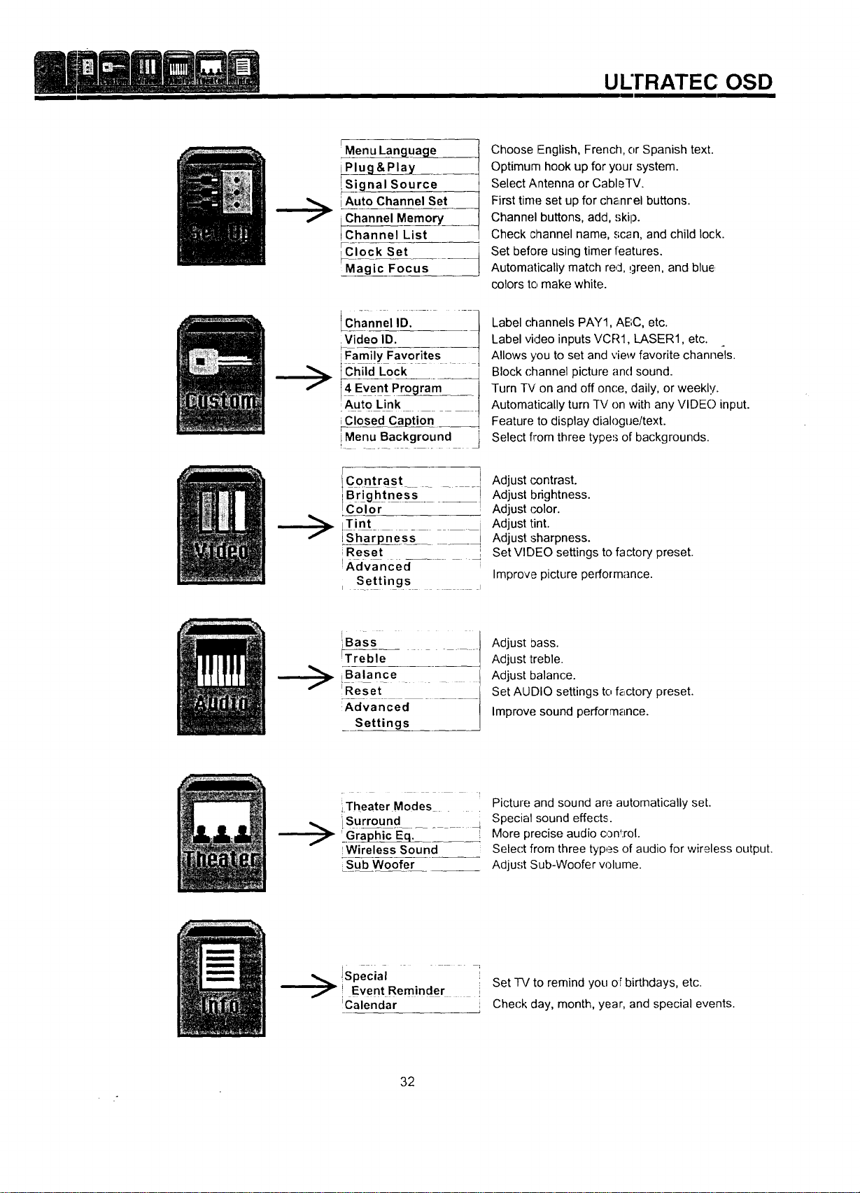
Menu Langua___
Plug &Play____
_ignal Source
iAuto Channel Set
Channel Memory
Channel List
_,Clock Set
I
iMagic Focus
Chan"el.......
iFamily Favorites 1
IChiid Lock,- _
• m
Auto Link
iClosed Caj)tion
iMenu Background
IContrast I
Color
LTint
LiSharpness " " --I
;Reset t
i
_XdVanced_- - -
[ Settings _ s
Choose English, French, or Spanish text.
Optimum hook up for your system.
Select Antenna or CableTV.
First time set up for che,nrel buttons.
Channel buttons, add, skip.
Check channel name, scan, and child lock.
Set before using timer features.
Automatically match red, !green, and blue
colors to make white.
Label channels PAY1, ABC, etc.
Label video inputs VCR1, LASER1, etc.
Allows you to set and view favorite channels.
Block (-hannel picture and sound.
Turn TV on and off once, daily, or weekly.
Automatically turn TV on with any VIDE() input.
Feature to display dialogue/text.
Select from three types of backgrounds.
Adjust contrast.
Adjust brightness.
Adjust color.
Adjust tint.
Adjust sharpness.
Set VIDEO settings to factory preset.
Improve picture performance.
f
[ -
_B_ SS _ .
Treble
iBalance
L ....
!Reset
Advanced
Settings
Adjust bass.
Adjust treble.
Adjust balance.
Set AUDIO settings to f_,ctory preset.
Improve sound performance.
>
iTheater Modes
iSurround
'_Gra_ic-Eq._- - _,
IWirelessSound
Sub Woofer
Picture and sound are automatically set.
Special sound effects.
More precise audio con_:rol.
Selec't from three types of audio for wir,£less output.
Adjust Sub-Woofer w)lume.
!Specval I
,! EventReminder i Set _/to remind you of birthdays, etc.
!Calendar : Check day, month, year, and special events.
32
SET UP
II
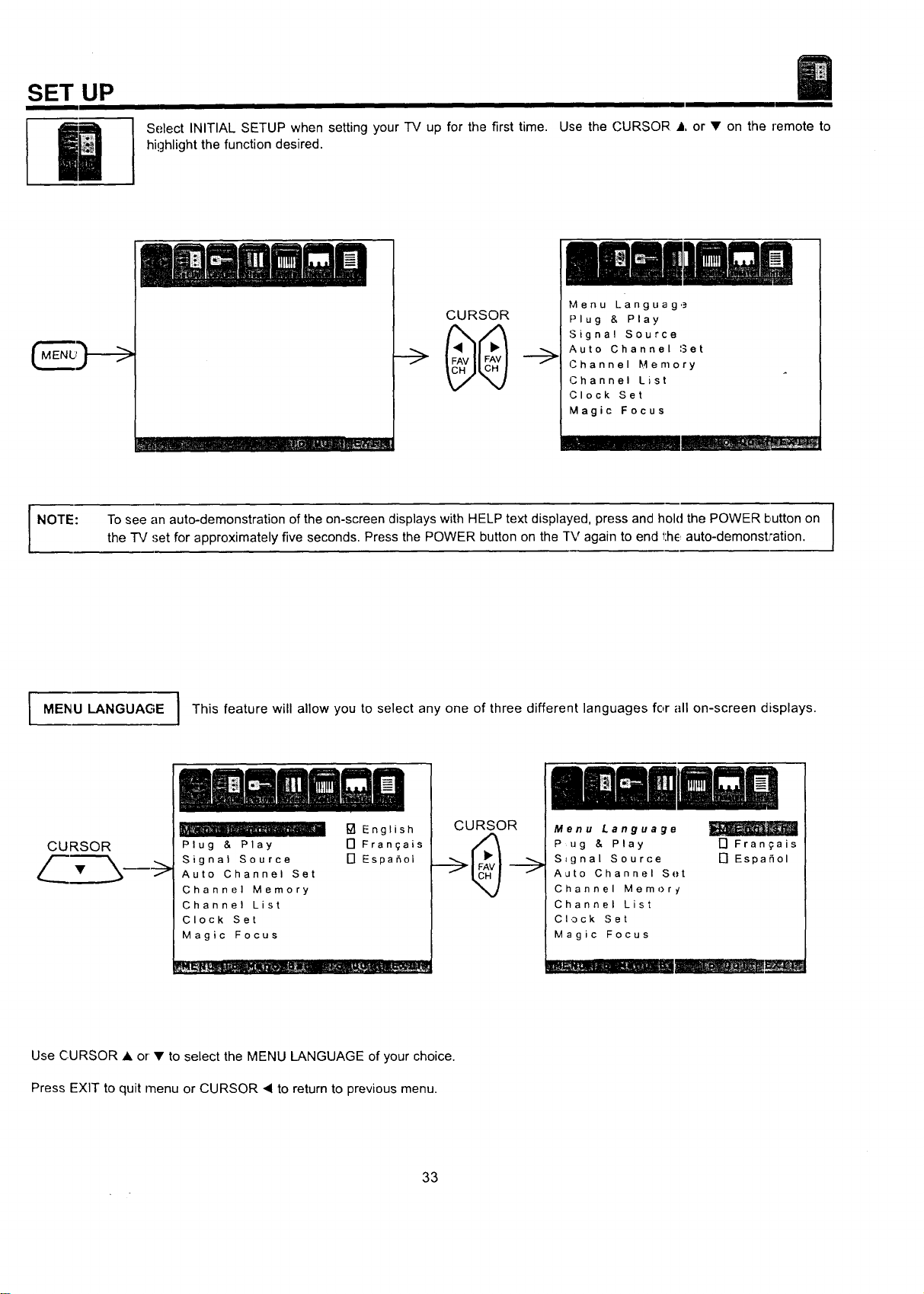
Select INITIAL SETUP when setting your TV up for the first time. Use the CURSOR • or • on the remote to
highlight the function desired.
t Hrl __Jill _ J.._,
CURSOR
Menu Languag,.=
Plug & Play
Signal Source
Auto Channel 3et
Channel Memory
Channel List
Clock Set
Magic Focus
NOTE:
I
To see an auto-demonstration of the onIscreen displays with HELP text displayed, press and hold the POWER button on [
the "IV ,'let for approximately five seconds. Press the POWER button on the rv again to end 1:he,auto-demonstJ'ation.
I
MENU LANGUAGE I This feature will allow you to select any one of three different languages for all on-screen displays.
CURSOR
Plug & Play
Signal Source
Auto Channel Set
Channel Memory
Channel List
Clock Set
Magic Focus
[] English
N Fran_ais
[] Espa5ol
CURSOR
Menu Language
Pug & Play
S=gnal Source
Auto Channel Set
Channel Mernor _/
Channel List
CI,3ck Set
Magic Focus
17 Frangais
[7 EspaSol
mUm mm
Use CURSOR • or • to select the MENU LANGUAGE of your choice.
Press EXIT to quit menu or CURSOR • to return to previous menu.
33
PLUG & PLAY
SET UP
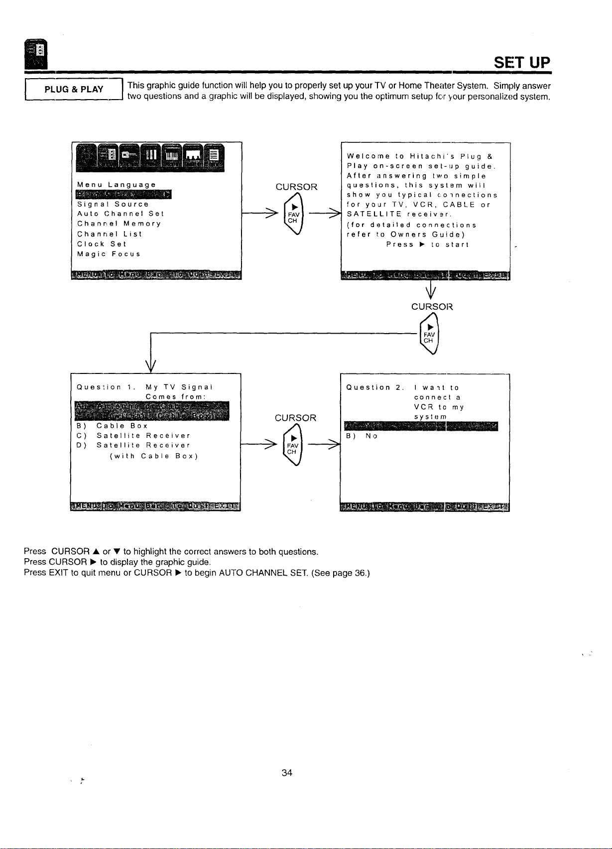
I This graphic guidofunctionwill help you to properly set up your TV or Home Theater System. Simply answer
two questions and a graphic will be displayed, showing you the optimum setup for tour personalized system.
Menu Language
Signal Source
Auto Channel Set
Channel Memory
Channel List
Clock Set
Magic Focus
CURSOR
Welcome to Hitachi's Plug &
Play on-screen set-up guide,
After answering two simple
questions, this system will
show you typical colnections
for your TV, VCR, CABLE or
SATELLITE receivar.
(for detailed connections
refer to Owners Guide)
Press • to start
CURSOR
Question 1. My TV Signal
Comes from:
B) Cable Box
C) Satellite Receiver
D) Satellite Receiver
(with Cable Box)
CURSOR
Question 2, I wa'_t to
connect a
VCR to my
sy st {.,m
....... . .. --
B ) N ,3
Press CURSOR • or • to highlight the correct answers to both questions.
Press CURSOR • to display the graphic guide.
Press EXIT to quit menu or CURSOR • to begin AUTO CHANNEL SET. (See page 36.)
, k.
34
SET UP
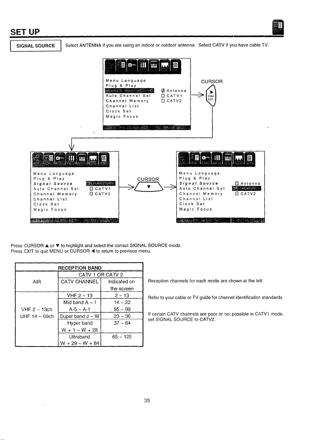
SIGNALSOURCE
Select ANTENNA if you are using an indoor or outdoor antenna. Select CATV if you have cable -fV.
Menu Language
Plug & Play
Auto Channel Set
Channel Memory
Channel List
Clock Set
Magic Focus
_J Antenna
[] CATVl
[] CATV2
CURSOR
Menu Language
Plug & Play
Signal Source
Auto Channel Set
Channel Memory
Channel List
Clock Set
Magic Focus
[] CATV1
[] CATV2
CURSOR
Menu Language
Plug & Play
Signal Source
Auto (..Channel Set
Channel Memory
Channel List
Clock Set
Magic Focus
[] Antenna
[] CATV2
---J.'i_ I H I
Press CURSOR A or • to highlight and select the correct SIGNAL SOURCE mode.
Press !--XIT to quit blENU or CURSOR • to return to previous menu.
AIR
VHF 2 - 13ch
UHF14-69ch
RECEPTION BAND
CA-IV 1 OR CATV 2
CA-IV CHANNEL Indicated on
VHF 2 - 13
Mid bandA~l
A-5 - A-1
Super band J - W
Hyper band
W+l ~W+28
Ultraband
W + 29 - W + 84
the screen
2-13
14 ~ 22
95 ~ 99
23 ~ 36
37 ~ 64
65 - 125
Reception channels for each mode are shown at the left.
Refer to your cable or TV guide for channel identification standards.
If certain CATV channels are poor or noL possible in CATV1 mode,
set SIGNAL SOURCE to CATV2.
35
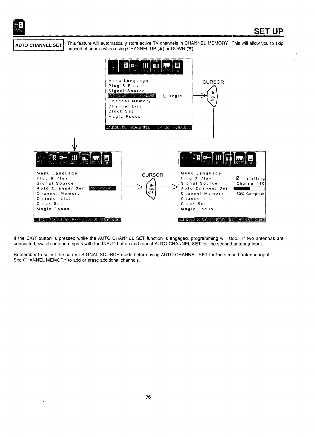
AUTO CHANNEL SET]
ii
This feature will automatically store active TV channels in CHANNEL MEMORY
unused channels when using CHANNEL UP (J,) or DOWN (T).
SET UP
"]-his will allow you to skip
Menu Language
Plug & Play
Signal Source
Channel Memory
Channel List
Clock Set
Magic Focus
[] Begin
Menu Language
Plug & Play
Signal Source
Auto Channel Set
Channel Memory
Channel List
Clock Set
Magic Focus
m_ .....
CURSOR
CURSOR
0mmaei o
Menu Language
Plug & Play
Signal Source
Auto Channel Set
Channel Memory
Channel List
Clock Set
Magic Focus
Installing
Channel 110
50% Comple,te
If the EXIT button is pressed while the AUTO CHANNEL SET function is engaged, programming will .stop. If two antennas are
connected, switch antenna inputs with the INPUT button and repeat AUTO CHANNEL SET for the secord antenna input.
Remember to select the correct SIGNAL SOURCE mode before using AUTO CHANNEL SET for the second antenna input.
See CHANNEL ME'MORY to add or erase additional channels.
36
SET UP
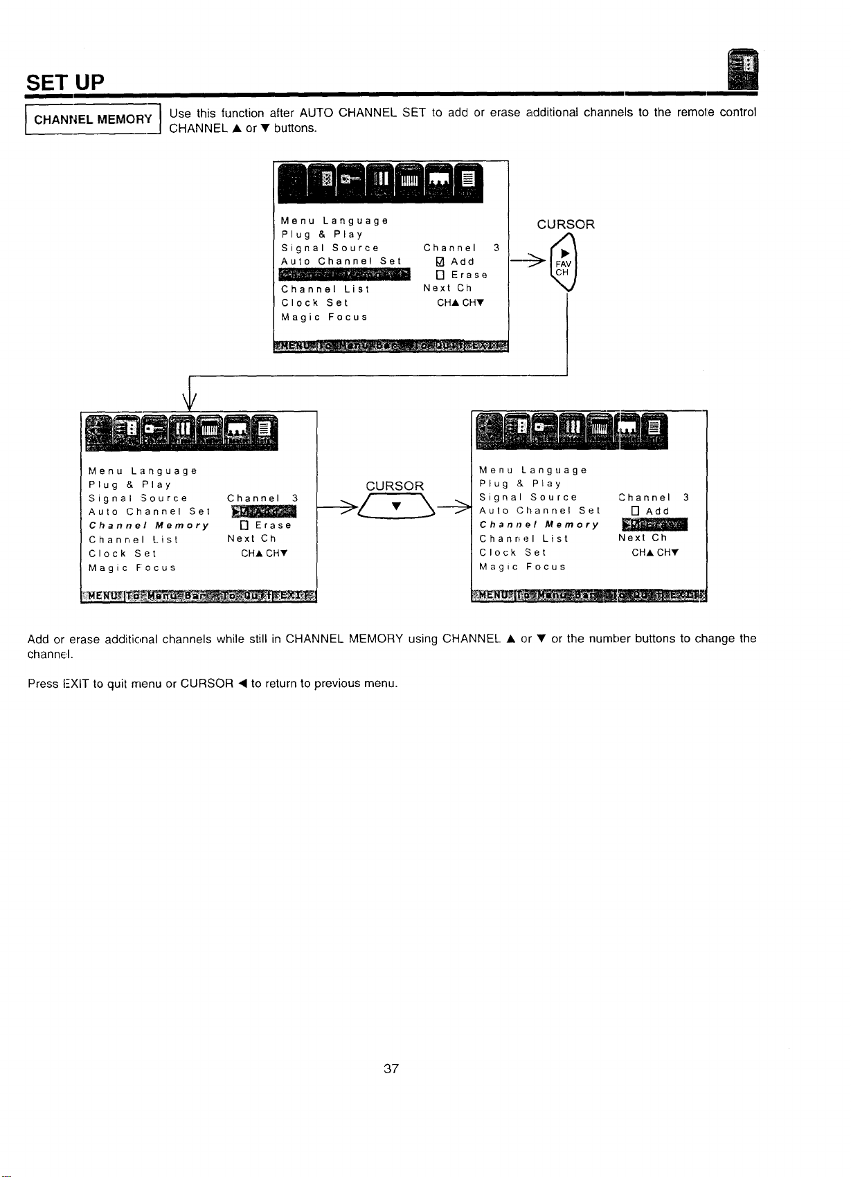
CHANNEL MEMORY
I
Use this function after AUTO CHANNEL SET to add or erase additional channels to the remote control
CHANNEL • or • buttons.
Menu Language
Plug & Play
Signal Source Channel
Auto Channel Set [] Add
....... - [] Erase
Channel List Next Ch
Clock Set CHA CHY
Magic Focus
CURSOR
¢
Menu Language
Plug & Play
Signal Source
Auto Channel Set
Channel Memory
Channel List
Clock Set
Magic Focus
Channel 3
[] Erase
Next Ch
CHA CH,
CURSOR
,,
Menu Language
Plug & Play
Signal Source
Auto (Channel Set
Channel Memory
Channel List
Clock Set
Magic Focus
Channel 3
[] Add
Next Ch
CHA CHY
Add or erase additional channels while stillin CHANNEL MEMORY using CHANNEL • or • orthe number buttons to change the
channel.
Press FXIT to quit menu or CURSOR ,q to return to previous menu.
37
I
CHANNELLIST
SET UP
i
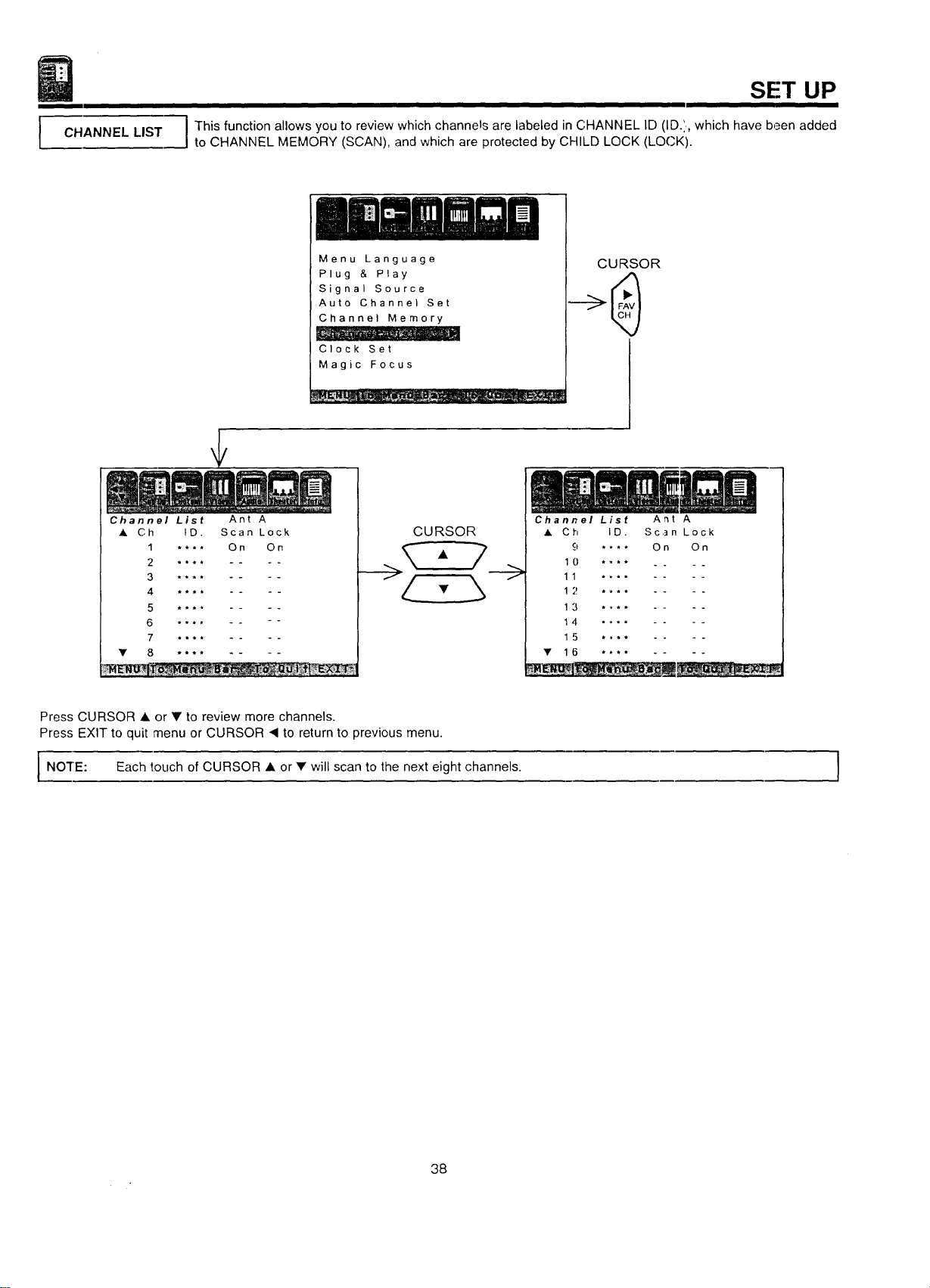
I This function allows you to review which channels are labeled in CHANNEL ID (ID.',, which have been added
to CHANNEL MEMORY (SCAN), and which are protected by CHILD LOCK (LOCK).
Menu Language
Plug & Play
Signal Source
Auto Channel Set
Channel Memory
Clock Set
Magic Focus
CURSOR
Channel List Ant A
• Ch ID. Scan Lock
1 .... On On
2 **** ....
3 **** ....
4 **** ....
5 **** ....
6 **** -- --
7 **-* ....
• 8 ........
CURSOR
Channel List Ant A
• Ch ID. Scan Lock
9 .... On On
1 0 .... . _
11 ......
1 2 ......
1 3 ......
14 ......
1 5 ......
• 16 ........
Press CURSOR • or • to review more channels.
Press EXIT to quit menu or CURSOR "_ to return to previous menu.
I NO'I"E: Each touch of CURSOR • • will to the next channels.
or scan eight
I
38
SET UP
II
CLOCK SET
Clock Set
I I
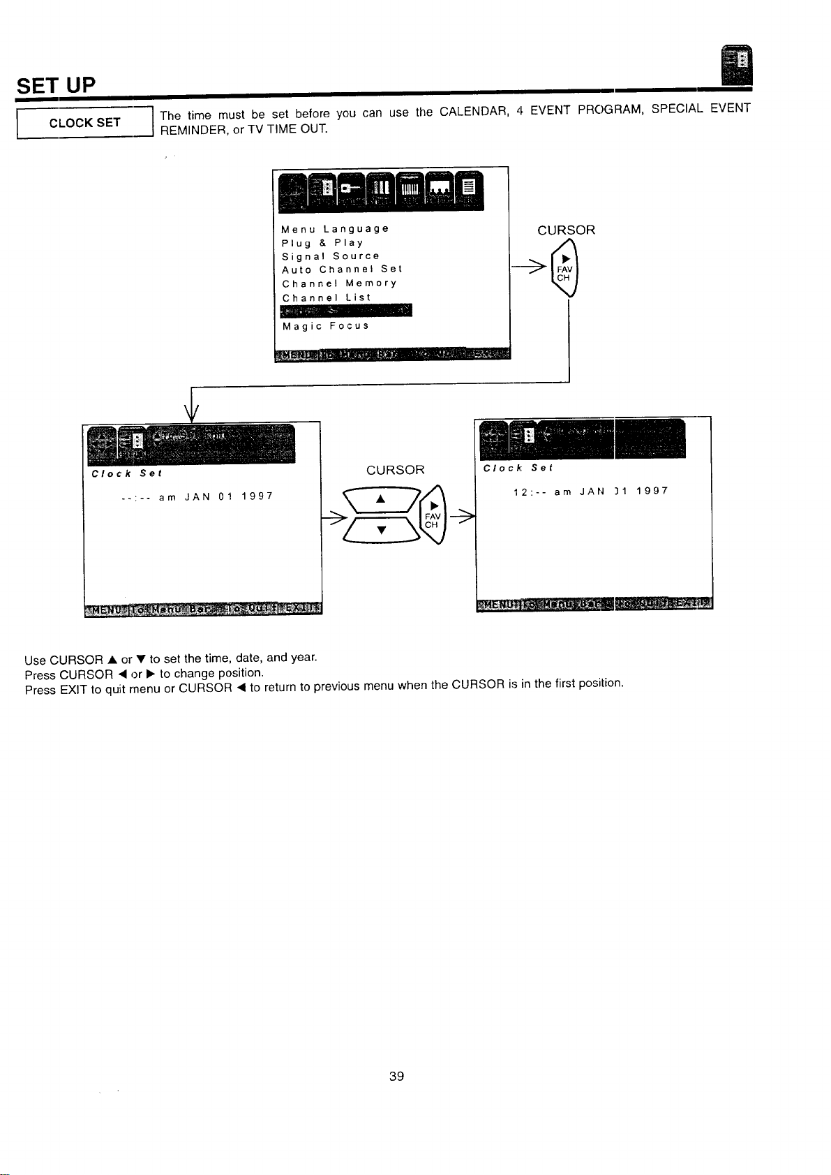
The time must be set before you can use the CALENDAR, 4 EVENT PROGRAM, SPECIAL EVENT
REMINDER, or TV TIME OUT.
Menu Language
Plug & Play
Signal Source
Auto Channel Set
Channel Memory
Channel List
Magic Focus
CURSOR
--:-- am JAN 01 1997
CURSOR
-->
Clock Set
12:-- am JAN 31 1997
Use CURSOR • or • to set the time, date, and year.
Press CURSOR • or • to change position.
Press EXIT to quit menu or CURSOR • to return to previous menu when the CURSOR is in the first position.
39
SET UP
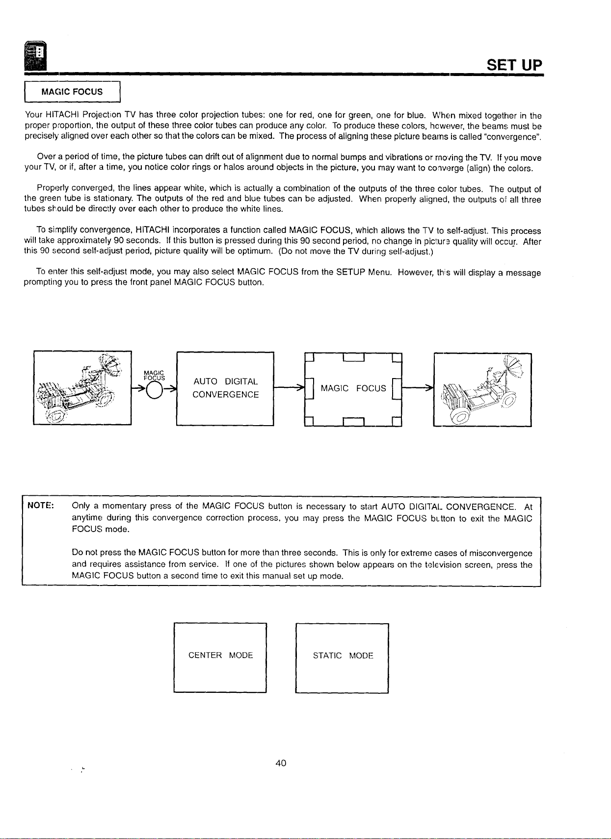
l MAGIC FOCUS
Your HITACHI Projection TV has three color projection tubes: one for red, one for green, one for blue. When mixed together in the
proper proportion, the output of these three color tubes can produce any color. To produce these colors, however, the beams must be
precisely aligned over each other so that the colors can be mixed. The process of aligning these picture beams is called "conw_rgence".
Over a period of time, the picture tubes can drift out of alignment due to normal bumps and vibrations or moving the TV. If you move
your TV, or if, after a time, you notice color rings or halos around objects in the picture, you may want to co'werge (align) the colors.
Properly converged, the lines appear white, which is actually a combination of the outputs of the three color tubes. The output of
the green tube is slationary. The outputs of the red and blue tubes can be adjusted. When properly aligned, the outputs oF all three
tubes sl_iould be directly over each other to produce the white lines.
To simplify convergence, HITACHI incorporates a function called MAGIC FOCUS, which allows the TV to self-adjust. This process
will take approximately 90 seconds. If this button is pressed during this 90 second period, no change in picl:ur_ quality will occur. After
this 90 second self-adjust period, picture quality will be optimum. (Do not move the TV during self-adjust.)
To enter this self-adjust mode, you may also select MAGIC FOCUS from the SETUP Menu. However, this will display a message
prompting you to press the front panel MAGIC FOCUS button.
MAGIC
FOCUS
AUTO DIGITAl..
CONVERGENCE
__..._>
_1 l I
MAGIC FOCUS
-I l--q
L
F
NOTE':
Only a momentary press of the MAGIC FOCUS button is necessary to start AUTO DIGITAL CONVERGENCE. At
anytime during this convergence correction process, you may press the MAGIC FOCUS bLtton to exit the MAGIC
FOCUS mode.
Do not press the MAGIC FOCUS button for more than three seconds. This is only for extreme cases of misconvergence
and requires assistance from service. If one of the pictures shown below appears on the television screen, press the
MAGIC FOCUS button a second time to exit this manual set up mode.
CENTER MODE
STATIC MODE
4O
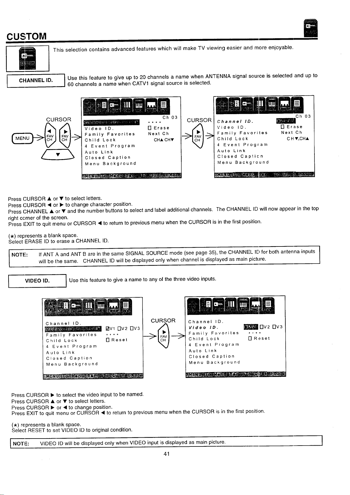
CUSTOM
This selection contains advanced features which will make TV viewing easier and more enjoyable.
I
CHANNEL ID.
JUse this feature to give up to 20 channels a name when ANTENNA signal source is selected and up to
60 channels a name when CATV1 signal source is selected.
CLIRSOR
, i •
Video ID.
Family Favorites
Child Lock
4 Event Program
Auto Link
Closed Caption
Menu Background
Oh 03
17 Erase
Next Ch
CH,I,CHV
CURSOR
Channel ID.
Video ID.
Family Favorites
Child Lock
4 Event Program
Auto Link
Closed Cap_icn
Menu Background
l_lC h 03
[] Erase
Next Ch
C H Y.CHA
Press CURSOR • or • to select letters.
Press CURSOR I or • to change character position.
Press CHANNEL • or • and the number buttons to select and label additional channels. The CHANNEL ID will now appear in the top
right corner of the screen.
Press E-XIT to quit menu or CURSOR • to return to previous menu when the CURSOR is in the first position.
(_) represents a blank space.
Select ERASE ID to erase a CHANNEL ID.
I NOTE: If ANT A and ANT B are in the same SIGNAL SOURCE mode (see page 35), the CHANNEL ID for both antenna inputs I
t
will be lhe same. CHANNEL ID will be displayed only when channel is displayed as main picture.
!
VIDEO ID.
I Use this feature to give a name to any of the three video inputs.
Channel ID.
1:71Vl FIv2 FIV3
Family Favorites ....
Child Lock [] Reset
4 Event Program
Auto Link
Closed Caption
Menu Background
__ : ......
CURSOR
Channel ID.
Video ID.
Family Favorites
Child Lock
4 Event Program
Auto Link
Closed Caption
Menu Background
Dv2 Dv3
[] Reset
Press CURSOR • to select the video input to be named.
Press CURSOR • or • to select letters.
Press CURSOR • or • to change position.
Press EXIT to quit menu or CURSOR • to return to previous menu when the CURSOR is in the first position.
(_r) represents a blank space.
SelectRESET to set VIDEO ID to original condition.
I NOTI=: VIDEO ID will be displayed only when VIDEO input is displayed as main picture. I
41
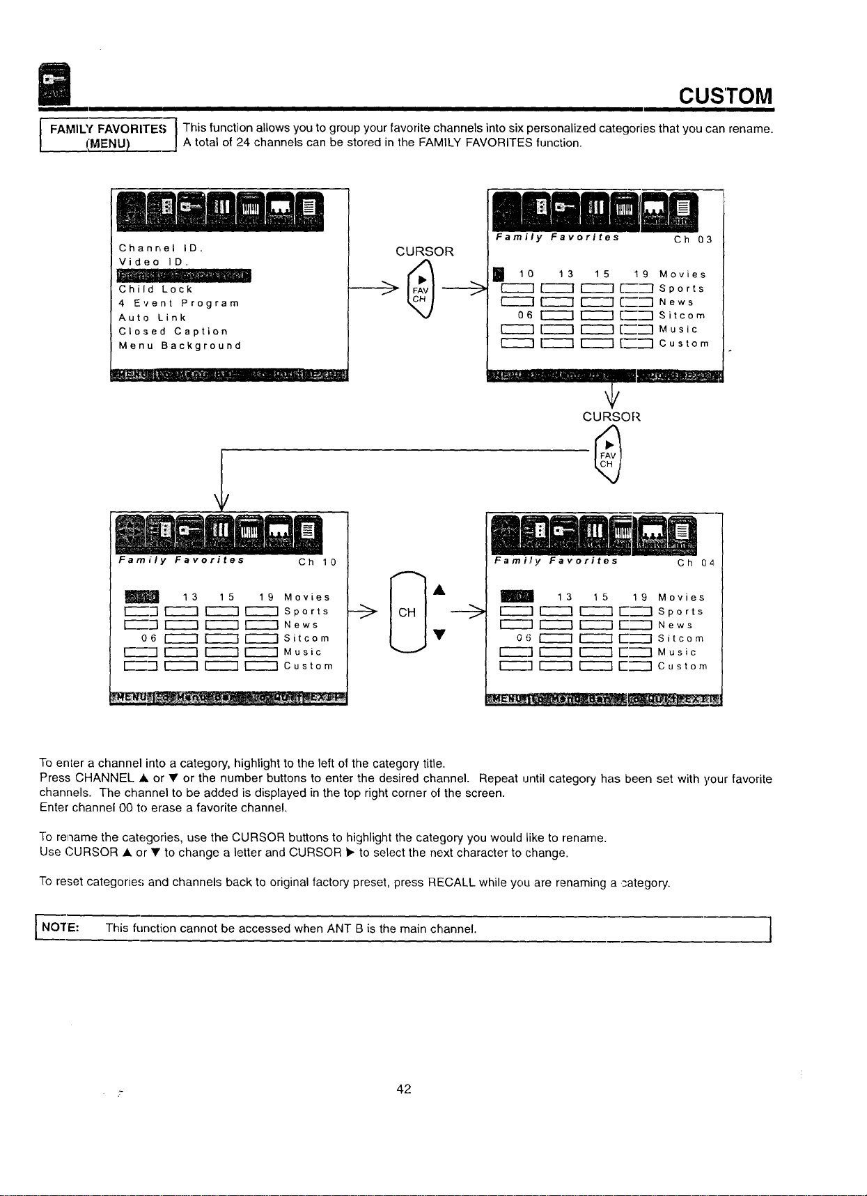
CUSTOM
I FAMIU( FAVORITE.=; 1 This function allows you to group your favorite channels into six personalized categories that you can rename.
IIMENU) _j A total of 24 channels can be stored in the FAMILY FAVORITES function.
Channel ID.
Video ID.
Child Lock
4 Event Program
Auto Link
Closed Caption
Menu Background
CURSOR
Family Favorites Ch 03
I 10 13 15 19 Movies
r-_ _---1 _ [_--I Sports
[-_ ["_ _ [_'--I News
06 _ r-_ [_--I Sitcom
r_ [--_ r_ [_-"l Music
[-'_ _ [_--'1 Custom
_.-.,. ............. _._--::_--
Family Favorites Ch 10
m
13 15 19 Movies
[Z_"] r-----I r_ r_ Sports
[_-] r_ F-_ r-_ News
06 i-_ _ ['_ Sitcom
E_-] r_ r_ r-_ Music
_'_-"-] [---"-7 _ _ Custom
_-->
t/
CURSOR
Ch 04
Family Favorites
13 15 19 Movies
_ r----q [-----] Sports
[-----q _ [-"'_-] News
06 I_ _ [-"_-I Sitcom
_] r_ _ [-'_"q Music
r----]r_ [iiiii13E-'---] Custom
To enter a channel into a category, highlight to the left of the category title.
Press CHANNEL • or • or the number buttons to enter the desired channel. Repeat until category has been set with your favorite
channels. The channel to be added is displayed in the top right corner of the screen.
Enter channel 00 to erase a favorite channel.
To rename the categories, use the CURSOR buttons to highlight the category you would like to rename.
Use CURSOR • or • to change a letter and CURSOR _. to select the next character to change.
To reset categories and channels back to original factory preset, press RECALL while you are renaming a _-ategory.
I NO'rE: This function cannot be accessed when ANT B is the main channel. I
._ 42
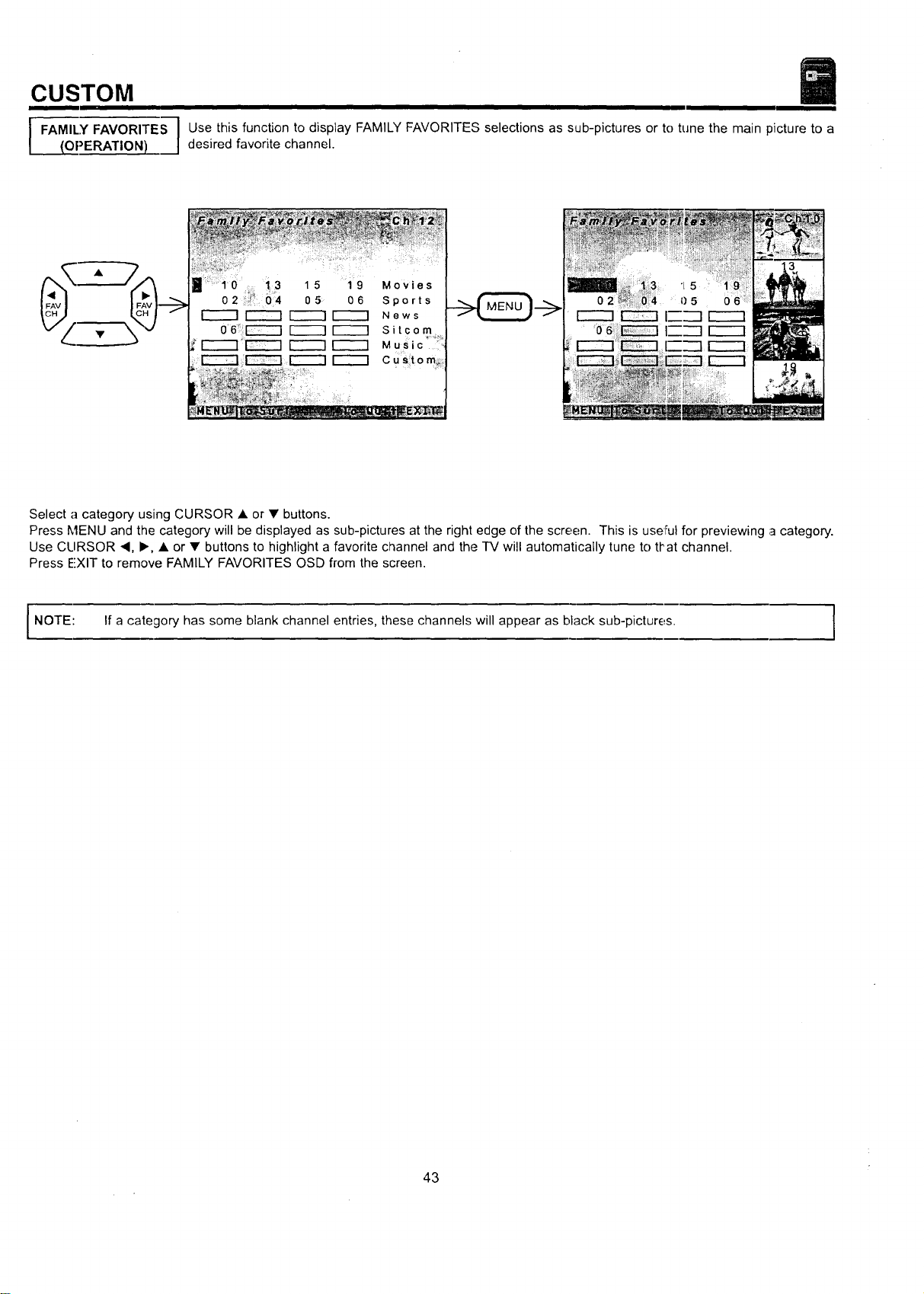
CUSTOM
I I
I FAMILY FAVORITES I Use this function to display FAMILY FAVORITES selections as sub-pictures or to tune the main picture to a
{OPERATION) desired favorite channel.
10 13 15 19 Movies
02 " 04 05 06 Sports
I-'-"-'1 _ _ News
06 [-----7 _ I-_ Sitcom
[-_ Music '
Custom_.
Select a category using CURSOR • or • buttons.
Press MENU and the category will be displayed as sub-pictures at the right edge of the screen. This is useful for previewing a category.
Use CLIRSOR ,, I_, • or • buttons to highlight a favorite channel and the TV will automatically tune to that channel.
Press EXIT to remove FAMILY FAVORITES OSD from the screen.
NOTE: If a category has some blank channel entries, these channels will appear as black sub-pictures. I
43
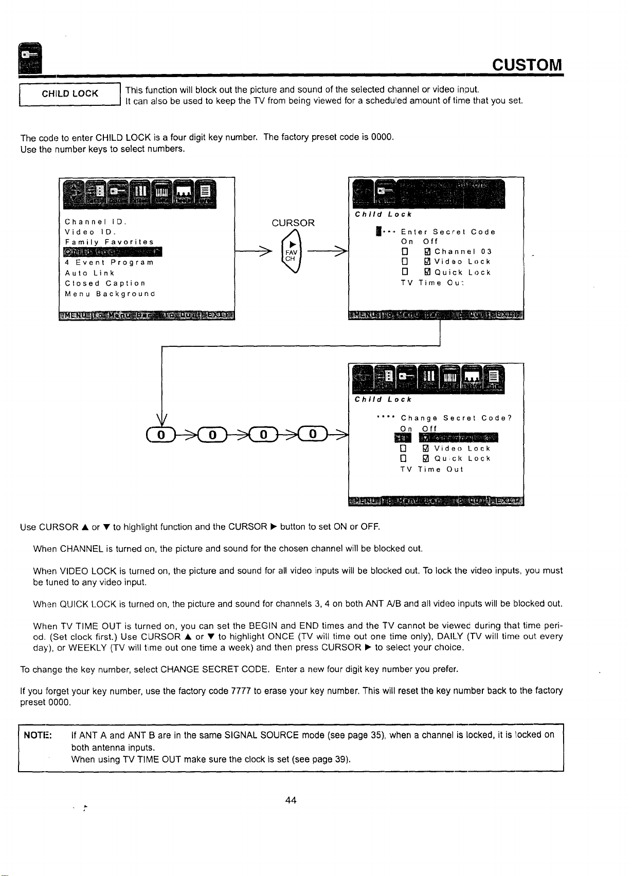
CHllLD LOCK
CUSTOM
I
' This function will block out the picture and sound of the selected channel or video in]3ut.
It can also be used to keep the TV from being viewed for a schedu!led amount of time that you set.
The code to enter CHILD LOCK is a four digit key number. The factory preset code is 0000.
Use the number keys to select numbers.
Channel ID.
Video ID.
Family Favorites
_ __ • .... c-
4 Event Program
Auto Link
Closed Caption
Menu Backgrouncl
CURSOR
Child Lock
Enter Secret Code
On Off
F] [] Channel 03
[] [] Video Lock
[] [] Qu ck Lock
TV Time Ou':
" - . •..... -
1
\
(3
/
0 0 0
Child Lock
.... Change Secret Code?
On Off
[] [] Video Lock
[] [] Qu ck Lock
TV Time Out
Use CURSOR • or • to highlight function and the CURSOR • button to set ON or OFF.
When CHANNEL is turned on, the picture and sound for the chosen channel will be blocked out.
When VIDEO LOCK is turned on, the picture and sound for all video inputs will be blocked out. To lock the video inputs., you must
be tuned to any video input.
When QUICK LOCK is turned on, the picture and sound for channels 3, 4 on both ANT ,_B and all video inputs will be blocked out.
When TV TIME OUT is turned on, you can set the BEGIN and END times and the TV cannot be vlewec during that time peri-
od. (Set clock first.) Use CURSOR • or • to highlight ONCE (TV will time out one time only), DAILY (TV will time; out every
day), or WEEKLY (TV will time out one time a week) and then press CURSOR • to select your choice.
To change the key number, select CHANGE SECRET CODE. Enter a new four digit key number you prefer.
If you forget your key number, use the factory code 7777 to erase your key number. This will reset the key number back to the factory
preset 0000.
NOTI-':
If ANT A and ANT B are in the same SIGNAL SOURCE mode (see page 35), when a channel is locked, it is _[ockedon
both antenna inputs.
When using TV TIME OUT make sure the clock is set (see page 39).
44
r-
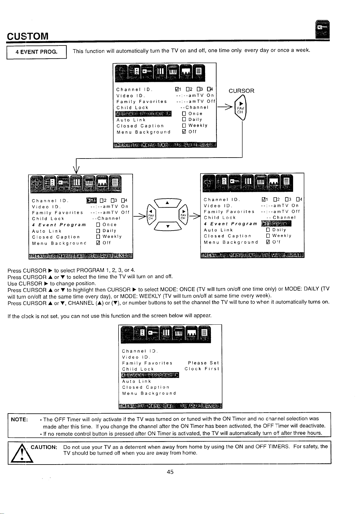
CUSTOM
I 4 EVENT PROG.
This function will automatically turn the TV on and off, one time only every day or once a week.
Channel ID. []1 D2 D3 D4
Video ID. --:--amTV On
Family Favorites --:--amTV Off
Child Lock --Channel
[]Once
Auto Link [] Daily
Closed Caption [] Weekly
Menu Background [] Off
: _. _ _ -__
CURSOR
Channel ID. _ D2 D3 D4
Video ID. --:--amTV On
Family Favorites --:--amTV Off
Child Lock --Channel
4 Event Program [] Once
Auto Link [] Daily
Closed Caption [] Weekty
Menu Background [] Off
Channel ID. fTt1 D2 D3 D4
Video ID. : amTV On
Family F:avorites --:--amTV Off
Child Lock -- Channel
4 Event Program
Auto Link I-I Daily
Closed Caption i-I Weekly
Menu Background I_10"f
Press CURSOR • to select PROGRAM 1,2, 3, or 4.
Press CURSOR • or • to select the time the TV will turn on and off.
Use CLIRSOR • to change position.
Press CURSOR • or • to highlight then CURSOR • to select MODE: ONCE (TV will turn on/off one time only) or MODE: DAILY (TV
will turn on/off at the same time every day), or MODE: WEEKLY (TV will turn on/off at same time every week').
Press CURSOR • or •, CHANNEL (A) or (V), or number buttons to set the channel the TV will tune to when it automatically turns on.
Ifthe clack is not set, you can not use this function and the screen below will appear.
Channel 1:3.
Video ID,
Family Favorites
Child Lock
Auto Link
Closed Caption
Menu Background
Please Set
Clock First
NOTE: • The OFF Timer will only activate if the TV was turned on or tuned with the ON Timer and no charnel selection was
made after this time. If you change the channel after the ON Timer has been activated, the OFF Timer will deactivate.
• If no remote control button is pressed after ON Timer is activated, the TV will automatically turn off after three hours.
AUTION: Do not u,';e your TV as a deterrent when away from home by using the ON and OFF "rIMERS. For safety, the
TV should be turned off when you are away from home.
45
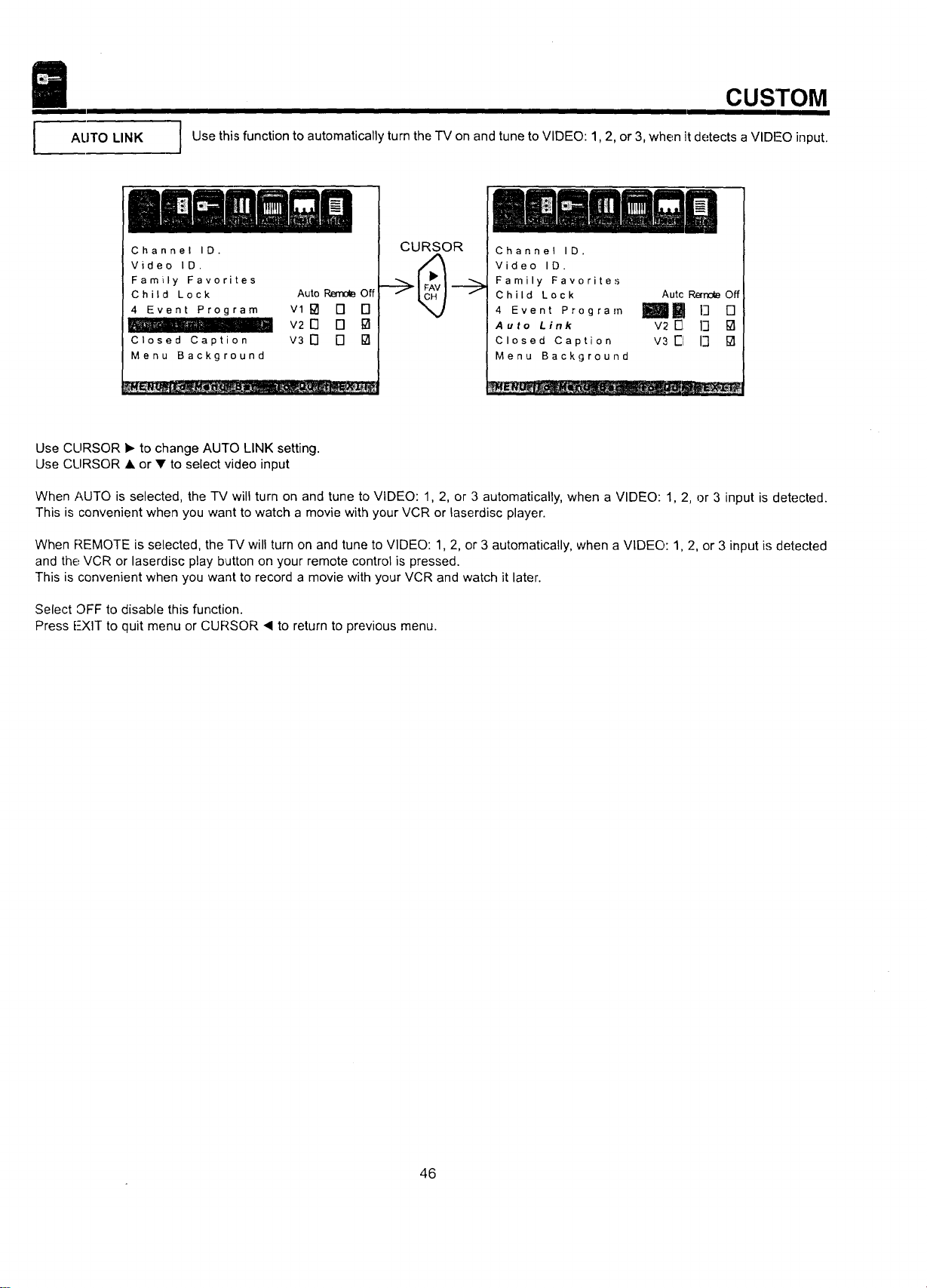
I
AUTO LINK
CUSTOM
Use this function to automatically turn the "I'Mon and tune to VIDEO: 1,2, or 3, when it detects aVIDEO input.
Channel ID.
Video ID.
Family Favorites
Child Lock
4 Event Program
II
Closed Caption
Menu Background
Auto _ Off
vlPl [] []
V2 [] [] []
v3 D [] []
CURSOR
.....' ill
m,,il_l_H_l ii iii1li =
m _l_,n ,=B n_lU
3hannel ID.
lideo ID.
:amily Favorites
3hild Lock
Event Program
_uto Link
3losed Caption
_lenu Background
Autc Remole Off
Imll []
v2 E3 13 []
v3 El 13 []
Use CLIRSOR I_ to change AUTO LINK setting.
Use CLIRSOR • or • to select video input
When AUTO is selected, the TV will turn on and tune to VIDEO: 1, 2, or 3 automatically, when a VIDEO: 1, 2, or 3 input is detected.
This is convenient when you want to watch a movie with your VCR or laserdisc player.
When P,EMOTE is selected, the TV will turn on and tune to VIDEO: 1, 2, or 3 automatically, when a VIDEO: 1, 2, or 3 input is detected
and the VCR or laserdisc play b_Jttonon your remote control is pressed.
This is convenient when you want to record a movie with your VCR and watch it later.
Select OFF to disable this function.
Press i--XIT to quit menu or CURSOR _ to return to previous menu.
46
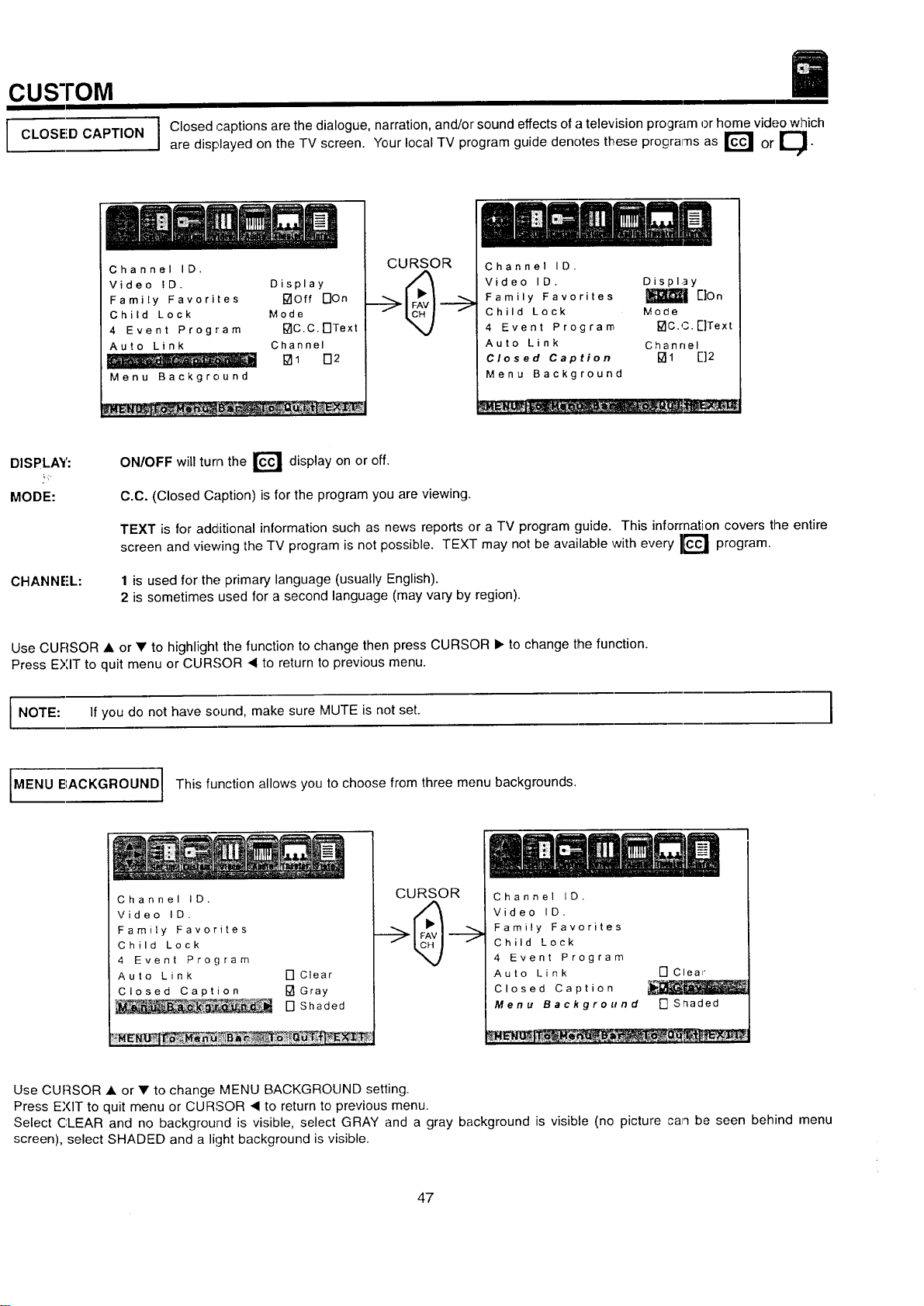
CUSTOM
I CLOSED CAPTION
I Closed captions are the dialogue, narration, and/or sound effects of a television program or home video which
are displayed on the TV screen. Your local TV program guide denotes these programs as r_ or ____.
Channel ID.
Video ID. Display
Family Favorites []Off DOn
Child Lock Mode
4 Event Program I_IC.C.F]Text
Auto Link Channel
..... o -,m [] 1 172
Menu Background
CURSOR
Channel ID.
Video ID. Display
Family Favorites _| [']On
Child Lock Mode
4 Event Program []C.C.E]Text
Auto Link Channel
Closed Caption []1 []2
Menu Background
D SPLAY:
MODE:
CHANNE'L:
ON/OFF will turn the r_ display on or off.
c.c. (Closed Caption) is for the program you are viewing.
TEXT is for additional information such as news reports or a TV program guide. This information covers the entire
screen and viewing the TV program is not possible. TEXT may not be available with every I[_ program.
1 is used for the primary language (usually English).
2 is sometimes used for a second language (may vary by region).
Use CURSOR • or • to highlight the function to change then press CURSOR • to change the function.
Press EXIT to quit menu or CURSOR • to return to previous menu.
i NOTE:
If you do not have sound, make sure MUTE is not set. I
MENU BACKGROUND 1 This function allows you to choose from three menu backgrounds.
Channel ID.
Video ID.
Family Favorites
Child Lock
4 Event Program
Auto Link [-I Clear
Closed Caption I_ Gray
__ [] Shaded
CURSOR
÷@÷
Channel ID.
Video ID.
Family Favorites
Child Lock
4 Event Program
Auto Link
Closed Caption
Menu Background
[] Cleal _
[] Srladed
Use CUF:ISOR • or • to change MENU BACKGROUND setting.
Press EXIT to quit menu or CURSOR • to return to previous menu.
Select CLEAR and no background is visible, select GRAY and a gray background is visible (no picture can be seen behind menu
screen), select SHADED and a light background is visible.
47
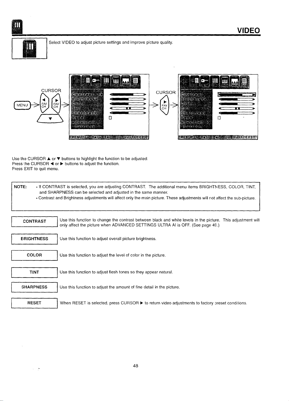
SelectVIDE()toadjustpicturesettingsandimprovepicturequality.
VIDEO
CURSOR
CURSOR
Use the CURSOR • or V buttons to highlight the function to be adjusted.
Press the CURSOR ,q or I_ buttons to adjust the function.
Press EXIT to quit menu.
NOTE:
• If CONTRAST is selected, you are adjusting CONTRAST. The additional menu items BRIGHTNESS, COLOR, TINT,
and SHARPNESS can be selected and adjusted in the same manner.
• Contrast and Brightness adjustments will affect only the main picture. These adjustments will not affect the sub-picture.
I
I
I
I
CONTRAST
BRIGHTNESS
COLOR
TINT
SHARPNESS
RESET
Use this function to change the contrast between black and white levels in the picture. This adjustment will
only affect the picture when ADVANCED SETTINGS ULTRA AI is OFF. (See page 4c,.)
I Use this function to adjust overall picture brightness.
Use this function to adjust the level of color in the picture.
I Use this function to adjust flesh tones so they appear natural.
Use this function to adjust the amount of fine detail in the picture.
I When RESET is selected, press CURSOR _. to return video adjustments to factory _reset condi;tions.
48
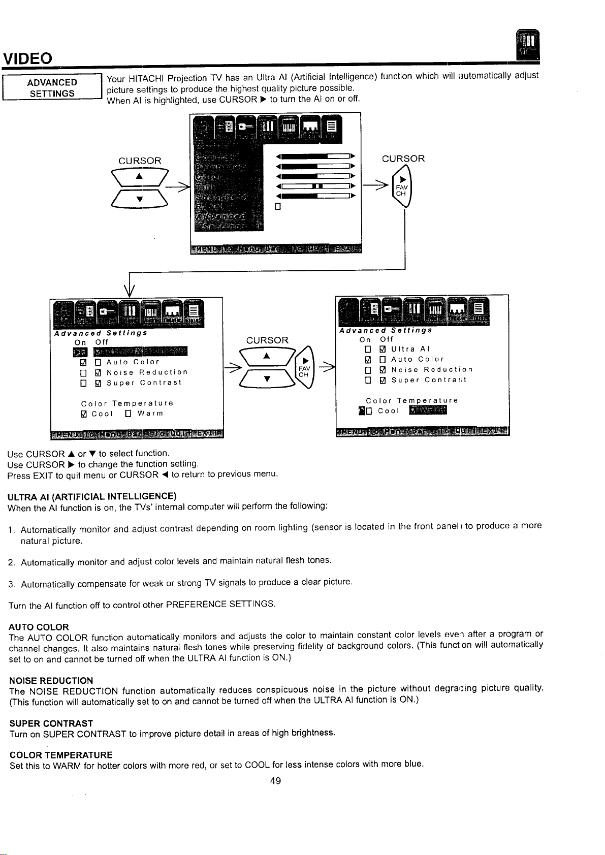
VIDEO
I ADVANCED
SEITINGS
I our HITACHI Projection TV has an Ultra AI (Artificial Intelligence) function which will automatically adjustpicture settings to produce the highest quality picture possible.
When AI is highlighted, use CURSOR • to turn the AI on or off.
CURSOR
Advanced Settings
CURSOR
On Off
[] [] Auto Color
[] [] Noise Reduction
[] [] Super Contrast
Color Temperature
[] Cool [] Warm
CURSOR
Use CURSOR • or • to select function.
Use CURSOR • to change the function setting.
Press EXIT to quit menu or CURSOR < to return to previous menu.
Advanced Settings
On Off
[] [] Ultra AI
[] [] Auto Color
[] [] Ncise Reduction
[] [] Super Contrast
Color Temperature
_n cool
ULTRA AI (ARTIFICIAL INTELLIGENCE)
When the AI function is on, the _/s' internal computer will perform the following:
1. Automatically monitor and adjust contrast depending on room lighting (sensor is located in the front laanel) to produce a more
natural picture.
2. Automatically monitor and adjust color levels and maintain natural flesh tones,
3. Autornatically compensate for weak or strong TV signals to produce a clear picture.
Turn the AI function off to control other PREFERENCE SETTINGS.
AUTO COLOR
The AU_,O COLOR function automatically monitors and adjusts the color to maintain constant color levels even after a program or
channel changes. It also maintains natural flesh tones while preserving t]delity of background colors. (This function will automatically
set to or and cannot be turned off when the ULTRA AI function is ON.)
NOISE REDUCTION
The NOISE REDUCTION function automatically reduces conspicuous noise in the picture without degrading picture quality.
(This function will automatically set to on and cannot be turned off when the ULTRA AI function is ON.)
SUPER CONTRAST
Turn on SUPER CONTRAST to improve picture detail in areas of high brightness.
COLOR TEMPERATURE
Set this to WARM for hotter colors with more red, or set to COOL for less intense colors with more blue.
49
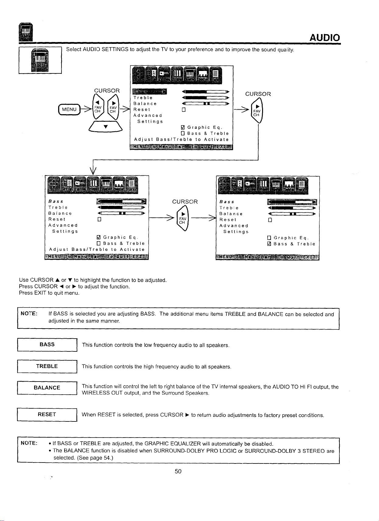
Select AUDIO SETTINGS to adjust the TV to your preference and to improve the sound quality.
AUDIO
CURSOR
<1 " IP"
Treble 41 " II_-
Balance <u mm ]ll_
Reset []
Advanced
Settings
[] Graphic Eq.
[] Bass & Treble
Adjust Bass/Treble to Activate
__nlmm
CURSOR
Bass
Treble 411 I Ili_
Balance <t im i11_
Reset []
Advanced
Settings
[] Graphic Eq.
[] Bass & Treble
Adjust Bass/Treble to Activate
__L -_._
CURSOR
f
Bass
T r e b I e 41 II II1_
B a la n c e 4r-_ • • l_
Reset I_}
Advanced
Settings
[] Graphic Eq.
[] Bass & Treble
Use CURSOR • or • to highlight the function to be adjusted.
Press CURSOR < or • to adjust the function.
Press EXIT to quit menu.
If BASS is selected you are adjusting BASS. The additional menu items TREBLE and BALANCF can be selected and
adjusted in the same manner.
I This function controls the low frequency audio to all speakers.
1
NOTE:
I BASS
TREBLE
BALANCE
RESET
This function controls the high frequency audio to all speakers.
This function will control the left to right balance of the TV internal speakers, the AUDIO TO HI FI output, the
WIRELESS OUT output, and the Surround Speakers.
When RESET is selected, press CURSOR • to return audio adjustrnents to factorv preset conditions.
NOTE:
• If BASS or TREBLE are adjusted, the GRAPHIC EQUALIZER will automatically be disabled.
• The BALANCE-- function is disabled when SURROUND-DOLBY PRO LOGIC or SURROUND-DOLBY 3 STEREO are
selected. (See page 54.)
5O
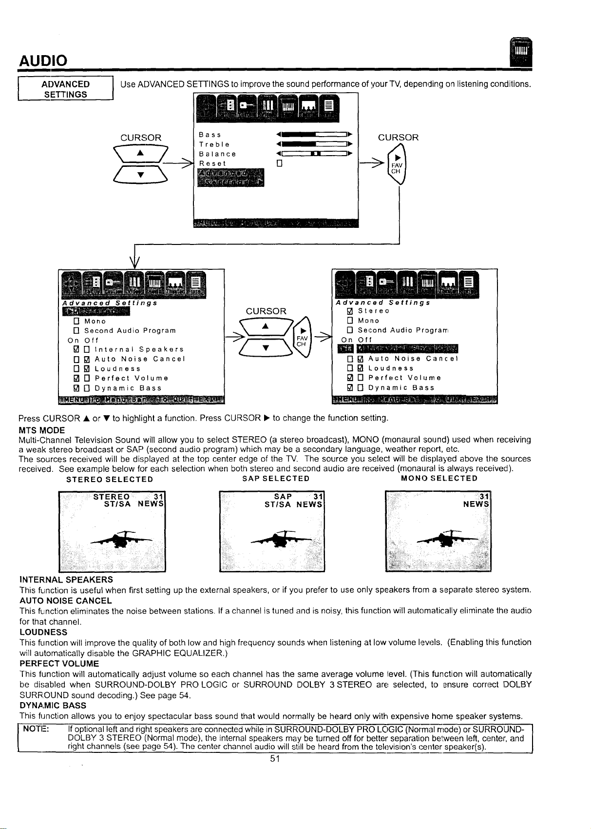
AUDIO
ADVANCED
SETTINGS
Use ADVANCED SETTINGS to improve the sound performance of your TV, depending on listening conditions.
CURSOR
B a s s _11 ' iI_
Treble • I1_
Balance "41 11 dl,,
Reset []
a_l_=_i_l ,,llllll .,.ill I Ill I III
CURSOR
Advanced Settings
[] Mono
[] Second Audio Program
On Off
[] [] Internal Speakers
[] [] Auto Noise Cancel
[] [] Loudness
[] [] Perfect Volume
[] [] Dynamic Bass
CURSOR
Advanced Settings
[] Stereo
[] Mono
[] Second Audio Program
On Off
[] [] Auto Noise Cancel
[] [] Loudness
[] [] Perfect Volume
[] [] Dynamic Bass
Press CURSOR • or • to highlight a function. Press CURSOR • to change the function setting.
MTS MODE
Multi-Channel Television Sound will allow you to select STEREO (a stereo broadcast), MONO (monaural sound) used when receiving
a weak stereo broadcast or SAP (second audio program) which may be a secondary language, weather report, etc.
The sources received will be displayed at the top center edge of the TV. The source you select will be displayed above the sources
received. See example below for each selection when both stereo and second audio are received (monaural is always received).
STEREO SELECTED SAP SELECTED MONO.€_EL.ECTED
ST EREO 31J
STISA NEWS I
This function is useful when first setting up the external speakers, or if you prefer to use only speakers from a separate stereo system.
AUTO NOISE CANCEL
This fL[nction eliminates the noise between stations. If a channel is tuned and is noisy, this function will automatically eliminate the audio
for that channel.
LOUDNESS
This function will improve the quality of both low and high frequency sounds when listening at low volume lew._ls. (Enabling this function
will automatically disable the GRAPHIC EQUALIZER.)
PERFECT VOLUME
This function will automatically adjust volume so each channel has the same average volume level. (This function will automatically
be disabled when SURROUND-DOLBY PRO LOGIC or SURROUND DOLBY 3 STEREO are selected, to ensure correct DOLBY
SURR.OUND sound decoding.) See page 54.
DYNAMIC BASS
This function allows you to enjoy spectacular bass sound that would normally be heard only with expensive home speaker systems.
NOTE: If optional left and right speakers are connected while in SURROUND-DOLBY PRO LOGIC (Normal mode) or SURROLIND-
DOLBY 3 STERE() (Normal mode), the internal speakers may be turned off for better separation between left, center, and
L right channels (see page 54). The center channel audio will still be heard from the television's center speaker(s),
51
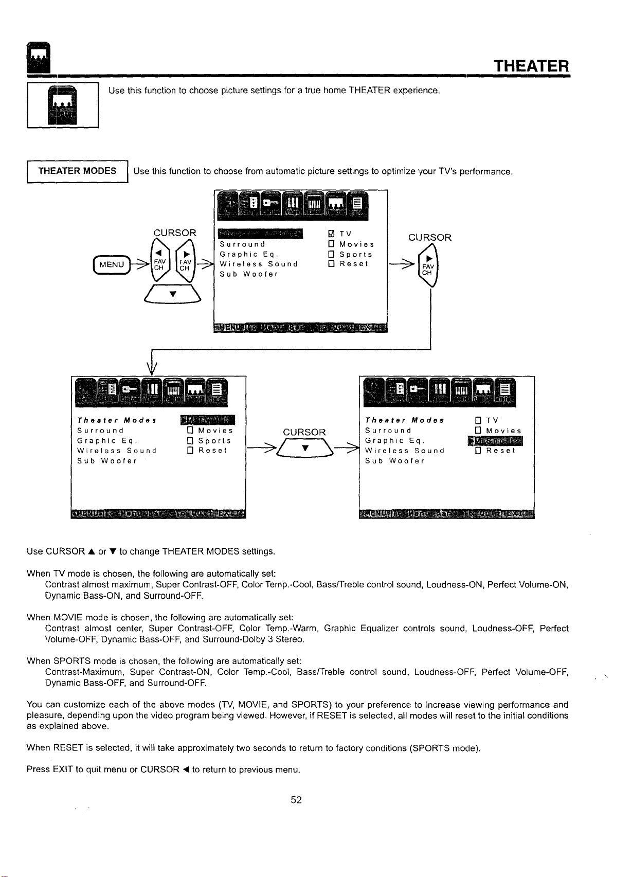
Use this function to choose picture settings for a true home THEATER experience.
THEATER
I THEATER MODES I Use this function to choose from automatic picture settings to optimize your TV's performance.
(CURSOR
I_ITV
Surround [] Movies
Graphic Eq. [] Sports
Wireless Sound [] Reset
Sub Woofer
CURSOR
Theater Modes
Surround [] Movies
Graphic Eq. [] Sports
Wireless Sound [] Reset
Sub Woofer
Theater Modes [] TV
Surround [] Movies
Graphic Eq. t_
Wireless Sound [] Reset
Sub Woofer
Use CURSOR • or • to change THEATER MODES settings.
When TV mode is chosen, the following are automatically set:
Contrast almost maximum, Super Contrast-OFF, Color Temp.-Cool, Bass/Treble control sound, Loudness-ON, Perfect Volume-ON,
Dynamic Bass-ON, and Surround-OFF.
When MOVIE mode is chosen, the following are automatically set:
Contrast almost center, Super Contrast-OFF, Color Temp.-Warm, Graphic Equalizer controls sound, Loudness-OFF, Perfect
Volume-OFF, Dynamic Bass-OFF, and Surround-Dolby 3 Stereo.
When SPORTS mode is chosen, the following are automatically set:
Contrast-Maximum, Super Contrast-ON, Color Temp.-Cool, Bass/Treble control sound, Loudness-OFF, Perfect Volume-OFF,
Dynamic Bass-OFF, and Surround-OFF.
You can customize each of the above modes (TV, MOVIE, and SPORTS) to your preference to increase viewing performance and
pleasure, depending upon the video program being viewed. However, if RESET is selected, all modes will reset to the initial conditions
as explained above.
When RESET is selected, it will take approximately two seconds to return to factory conditions (SPORTS rhode).
Press EXIT to quit menu or CURSOR ,q to return to previous menu.
52
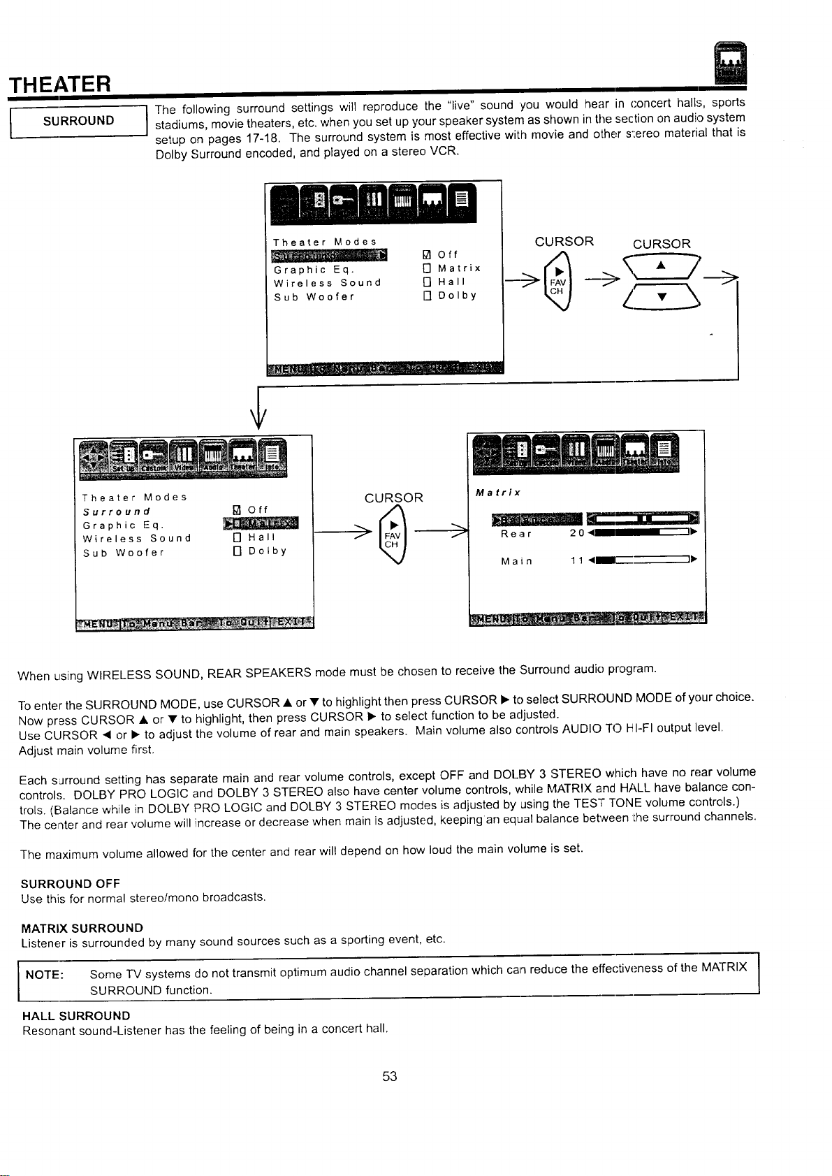
THEATER
I SURROUND
The following surround settings will reproduce the "live" sound 'you would hear in concert halls, sportsstadiums, movie theaters, etc. when you set up your speaker system as shown in the section on audio system
setup on pages 17-18. The surround system is most effective with movie and other s':ereo material that is
Dolby Surround encoded, and played on a stereo VCR.
Theater Modes
ta off
Graphic Eq. F'] Matrix
Wireless Sound [] Hall
Sub Woofer [] Dolby
CURSOR CURSOR
Theater Modes
Surround I_ Off
Graphic Eq.
Wireless Sound O Hall
Sub Woofer [] Dolby
CURSOR
>
Matrix
Rear 204 I1_
M a i n 1 1 <IB_I[ I_
When using WIRELESS SOUND, REAR SPEAKERS mode must be chosen to receive the :Surround audio program.
To enter the SURROUND MODE, use CURSOR • or • to highlight then press CURSOR • to select SURROUND MODE of your choice.
Now press CURSOR • or • to highlight, then press CURSOR • to select function to be adjusted.
Use CURSOR • or I_ to adjust the volume of rear and main speakers. Main volume also controls AUDIO TO HI-FI output level.
Adjust main volume first.
Each surround setting has separate main and rear volume controls, except OFF and DOLBY 3 STEREO which have no rear volume
controls. DOLBY PRO LOGIC and DOLBY 3 STEREO also have center volume controls, while MATRIX and HALL have balance con-
trois. (Balance while in DOLBY PRO LOGIC and DOLBY 3 STEREO modes is adjusted by using the TESq;"]'ONE volume controls.)
The center and rear volume will increase or decrease when main is adjusted, keeping an equal balance between Ihe surround channels.
The maximum volume allowed for the center and rear will depend on how loud the main volume is set.
SURROUND OFF
Use this for normal stereolmono broadcasts.
MATRIX SURROUND
Listener is surrounded by many sound sources such as a sporting event, etc.
NOTE: Some TV systems do not transmit optimum audio channel separation which can reduce the effectiw_ness of the MATRIX
SURROUND function.
HALL SURROUND
Resonant sound-Listener has the feeling of being in a concert hall.
53
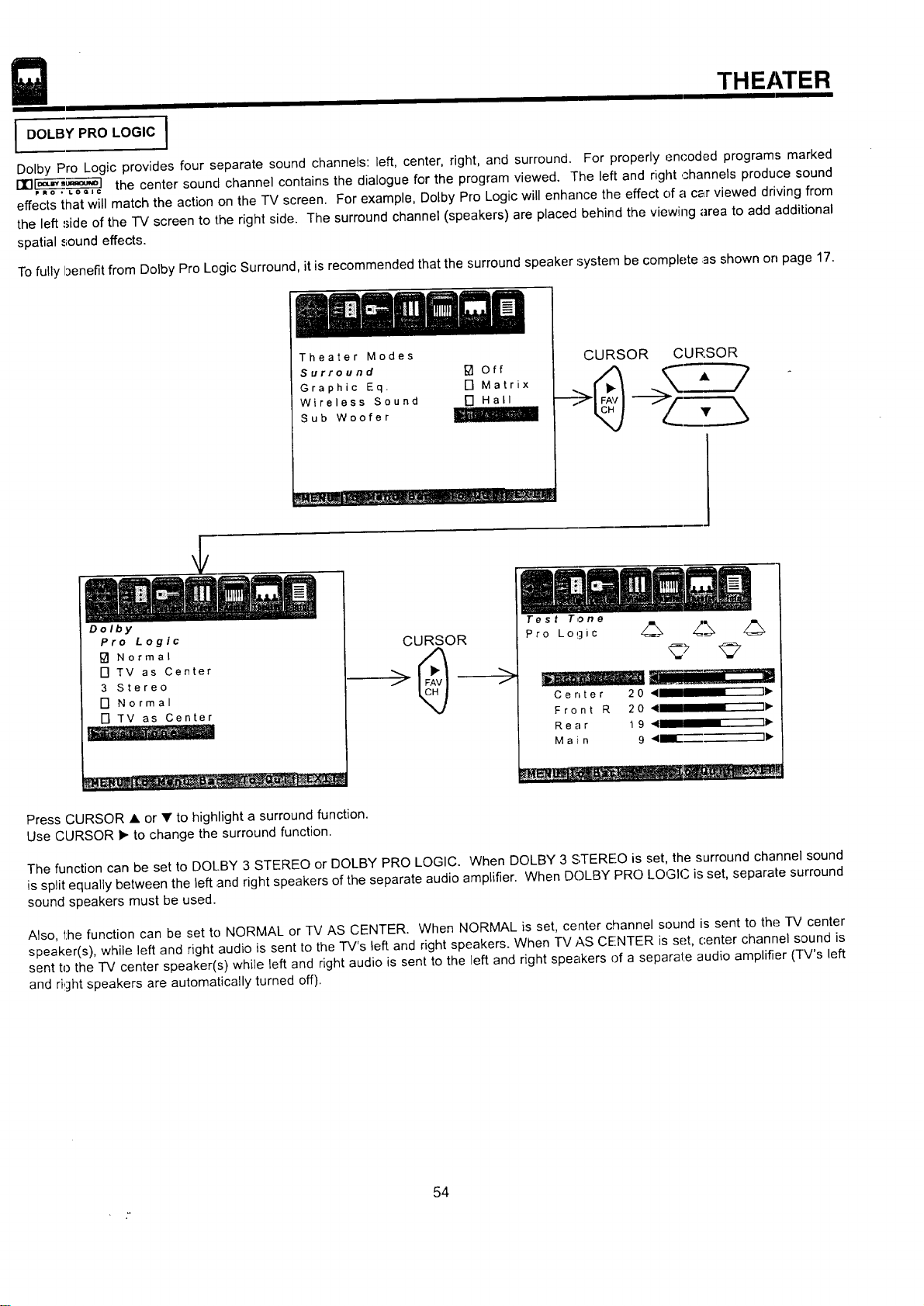
THEATER
I DOLBY PRO LOGIC I
Dolby Pro Logic provides four separate sound channels: left, center, right, and surround. For properly encoded programs marked
DIll- '=_°'_- ] the center sound channel contains the dialogue for the program viewed. The left and right channels produce sound
P_o • LOQIC
effects that will match the action on the TV screen. For example, Dolby Pro Logic will enhance the effect c)fa car viewed driving from
the left side of the -IV screen to the right side. The surround channel (speakers) are placed behind the viewing area to add additional
spatial sound effects.
To fully benefit from Dolby Pro Logic Surround, it is recommended that the surround speaker system be complete as shown on page 17.
Theater Modes
Surround [] Off
Graphic Eq. [] Matrix
Wireless Sound
Sub Woofer
CURSOR CURSOR
Dolby
Pro Logic
[] Normal
[] TV as Center
3 Stereo
[] Normal
[] TV as Center
i
CURSOR
>
Test Tone
Pro Logic z_ _"_ z_
Center 20 4 "11_
Front R 20 4 .... I_"
Rear 19 41 "ID,-
M a i n 9 41mllE_- 11_
Press CURSOR • or • to highlight a surround function.
Use CURSOR • to change the surround function.
The function can be set to DOLBY 3 STEREO or DOLBY PRO LOGIC. When DOLBY 3 STEREO is set, the surround channel sound
is split equally between the left and right speakers of the separate audio amplifier. When DC)LBY PRO LOGIC is set, separate surround
sound speakers must be used.
Also, the function can be set to NORMAL or TV AS CENTER. When NORMAL is set, center channel sound is sent to the "IV center
speaker(s), while left and right audio is sent to the TV's left and right speakers. When IV AS CENTER is set, center channel sound is
sent to the "IV center speaker(s) while left and right audio is sent to the left and right speakers of a separate audio amplifier (TV's left
and right speakers are automatically turned off).
54
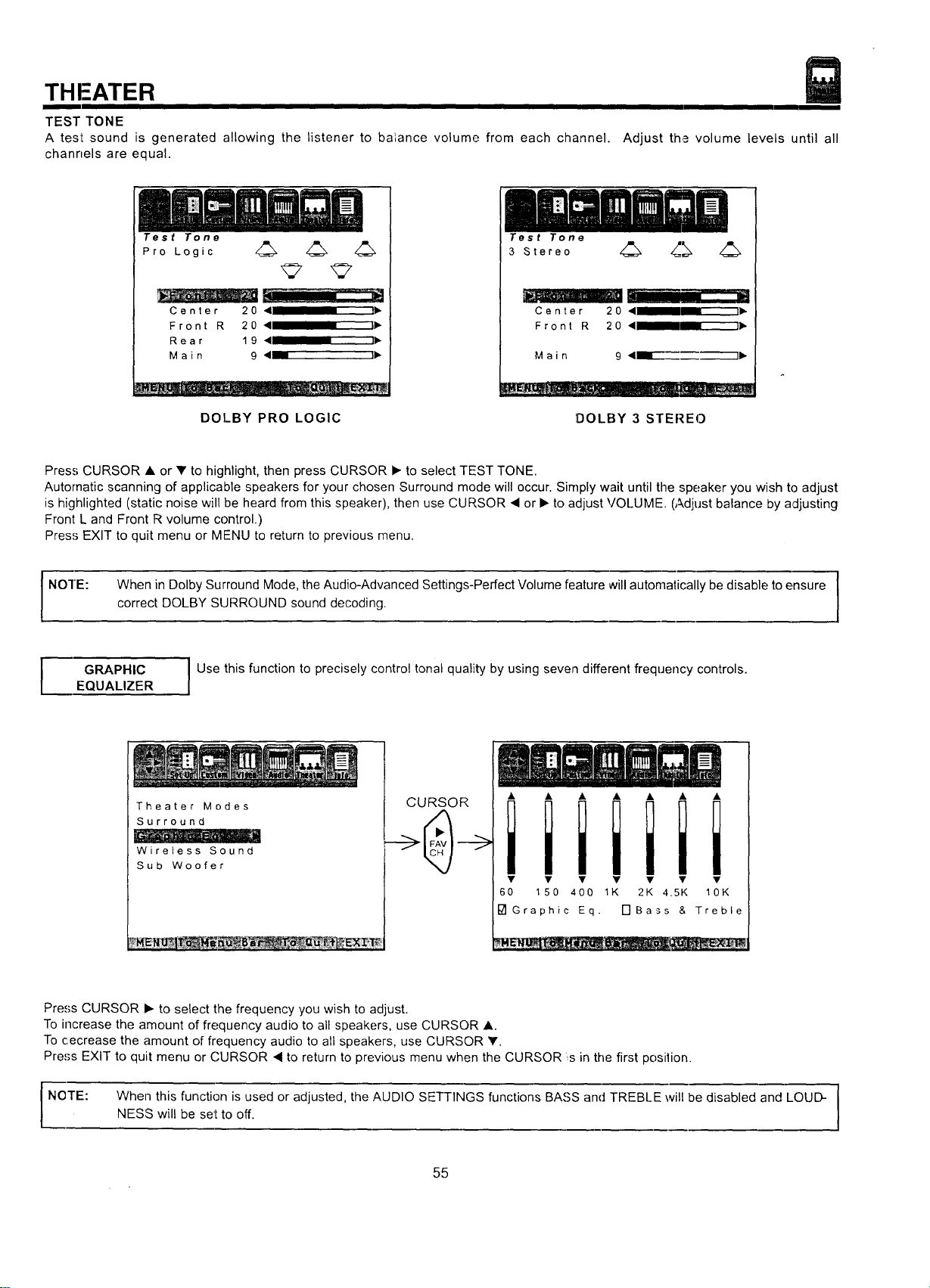
THFATER
TEST TONE
A test sound is generated allowing the listener to balance volume from each channel.
channels are equal.
Adjust the volume levels until all
Test Tone
Pro Logic 4_ 4_ 4_
Center 20 < I),
Front R 20 ,4 I1_
Rear 19 4 I1_
Main 9 <_ _
DOLBY PRO LOGIC
Test Tone
3 Stereo 4_ 4_[_;_ 4_
Center 20 < liP.
Front R 20 < 1)"
M a i n 9 ,<_--"-------_1_
!DOLBY 3 STEREO
Press CURSOR • or _' to highlight, then press CURSOR • to select TEST TONE.
Automatic scanning of applicable speakers for your chosen Surround mode will occur. Simply wait until the speaker you wish to adjust
is highlighted (static noise will be heard from this speaker), then use CURSOR • or • to adjust VOLUME. (Adjust balance by adjusting
Front L and Front R volume control.)
Press EXIT to quit menu or MENU to return to previous menu.
NOTE:
I
When in Dolby Surround Mode, the Audio-Advanced Settings-Perfect Volume feature will automatically be disable to ensure [
correct DOLBY SURROUND sound decoding.
I
I
GRAPHIC
EQUALIZER
I Use this function to precisely control tonal quality by using seven different frequency controls.
Theater Modes
Surround
Wireless Sound
Sub Woofer
CURSOR
iiiiiii
• • • Y • • •
60 150 400 1K 2K 4.5K 10K
I_1 Graphic Eq. [-]Bass & Treble
Press CURSOR • to select the frequency you wish to adjust.
To increase the amount of frequency audio to all speakers, use CURSOR •.
To cecrease the amount of frequency audio to all speakers, use CURSOR V.
Press EXIT to quit menu or CURSOR • to return to previous menu when the CURSOR s in the first position.
I NOTE: When this function is used or adjusted, the AUDIO SETTINGS functions BASS and TREBLE will be disabled and LOUD-NESS will be set to off.
55
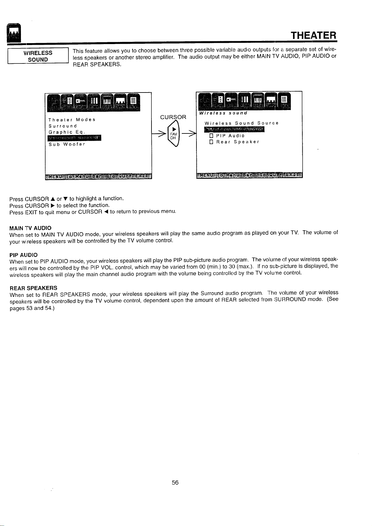
WIRELESS
SOUND
THEATER
I This feature allows you to choose between three possible variable audio outputs for _Lseparate set of wire-less speakers or another stereo amplifier. The audio output may be either MAIN rv AUDIO, PIP AUDIO or
REAR: SPEAKERS.
Theater Modes
Surround
Graphic Eq.
i
Sub Woofer
CURSOR
Wireless sound
Wireless Sound Source
[] PIP Audio
[] Rear Speaker
Press CURSOR • or • to highlight a function.
Press CURSOR • to select the function.
Press I-XIT to quit menu or CURSOR 4 to return to previous menu.
MAIN "l'V AUDIO
When set to MAIN TV AUDIO mode, your wireless speakers will play the same audio program as played on your TV. The volume of
your wireless speakers will be controlled by the TV volume control.
PIP ALIDIO
When ,_etto PIP AUDIO mode, !/our wireless speakers will play the PIP sub-picture audio program. The volurne of your wireless speak-
ers will now be controlled by the PIP VOL. control, which may be varied from 00 (min.) to 30 (max.). If no sub-picture is displayed, the
wireless speakers will play the main channel audio program with the volume being controlled by 1he TV volume control.
REAR SPEAKERS
When set to REAR SPEAKERS mode, your wireless speakers will play the Surround audio program. -l-he volume of your wireless
speakers will be controlled by the TV volume control, dependent upon the amount of REAR selected from SURROUND mode. (See
pages 53 and 54.)
56
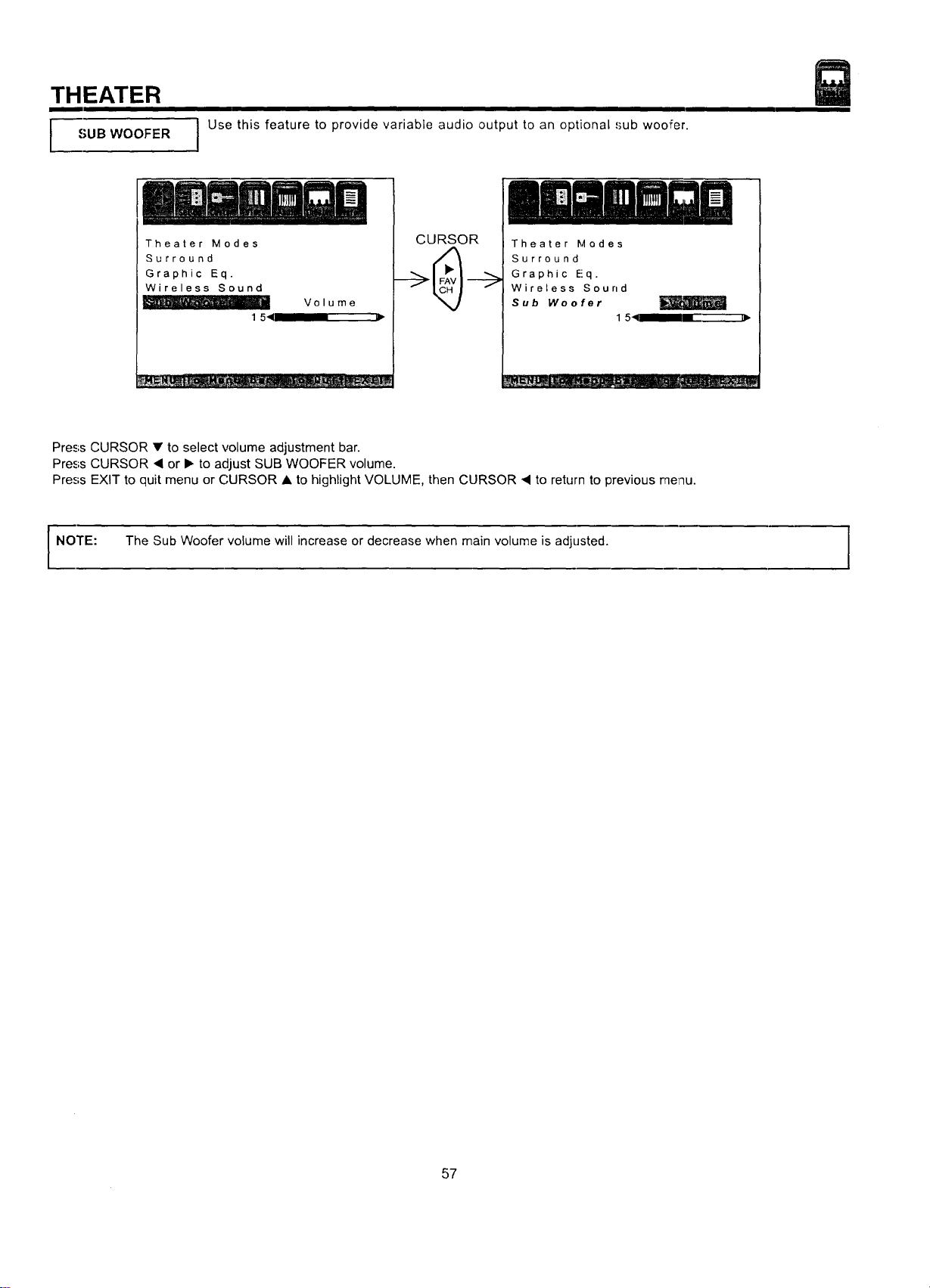
THEATER
SUB WOOFER
J Use this feature to provide variable audio output to an optional ,'_ubwoofer.
Theater Modes
Surround
Graphic Eq.
Wireless Sound
1 541
Volume
CURSOR
Theater Modes
Surround
Graphic E!q.
Wireless Sound
Sub Woofer
1 51__,
Press CURSOR • to select volume adjustment bar.
Press CURSOR • or I_ to adjust SUB WOOFER volume.
Press EXIT to quit menu or CURSOR • to highlight VOLUME, then CURSOR • to return to previous menu.
NOTE: The Sub Woofer volume will increase or decrease when main volume is adjusted. I
57
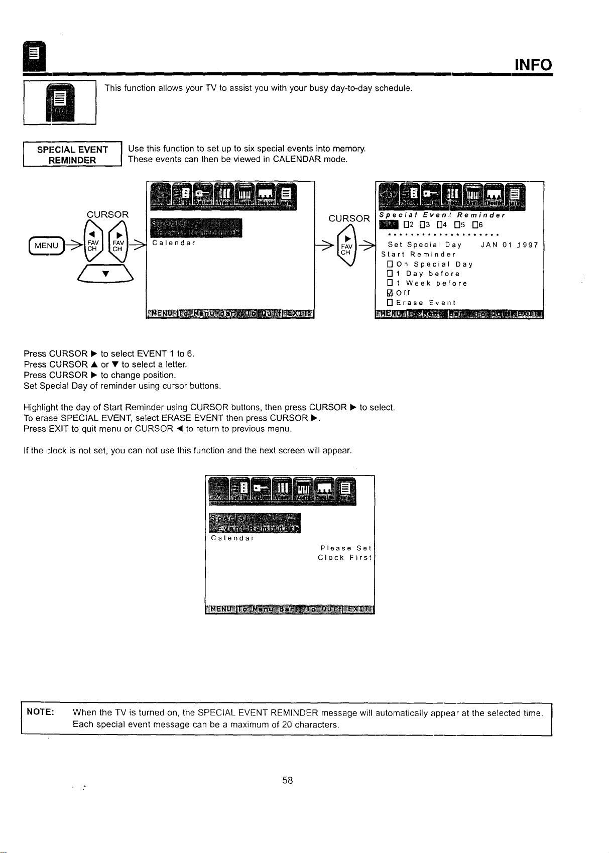
ThisfunctionallowsyourTVtoassistyouwithyourbusyday-to-dayschedule.
INFO
Z PI-'CIAL EVENT I Use this function to set up to six special events into memory.
REMINDER I These events can then be viewed in CALENDAR mode.
Calendar
CURSOR
Special Evenl! Reminder
D2 D3 []4 D5 D6
Set Special Day JAN 01 ..lq97
Start Reminder
DOn special Day
[] 1 Day before
[] 1 Week before
I_orf
[] Erase Event
Press CURSOR • to select EVENT 1 to 6.
Press CURSOR • or • to select a letter.
Press CURSOR • to change position.
Set Special Day of reminder using cursor buttons.
Highlight the day of Start Reminder using CURSOR buttons, then press CURSOR • to select.
To erase SPECIAL EVENT, select ERASE EVENT then press CURSOR •.
Press EXIT to quit menu or CURSOR _ to return to previous menu.
Ifthe ,Hock is not set, you can not use this function and the next screen will appear.
Calendar
Please Set
Clock First
i NO'rE:
I
When the TV is turned on, the SPECIAL EVENT REMINDER message will automatically appear at the selected time. I
Each special event message can be a maximum of 20 characters.
I
58
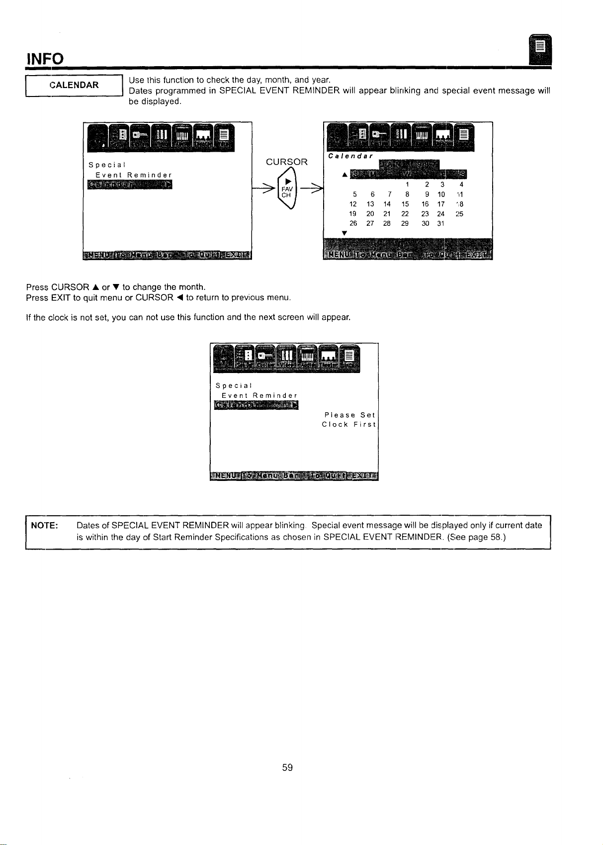
INFO
CALENDAR
I se this function to check the day, month, and year.
Dates programmed in SPECIAL EVENT REMINDER will appear blinking and special event message will
be displayed.
Special
Event Reminder
CURSOR
Calendar
1 2 3 4
5 6 7 8 9 10 il
12 13 14 15 16 17 "8
19 20 21 22 23 24 25
26 27 28 29 30 31
Press CURSOR • or • to change the month.
Press EXIT to quit menu or CURSOR I to return to previous menu.
If the clock is not set, you can not use this function and the next screen will appear.
Special
Event Reminder
Please Set
Clock First
NOTE: Dates of SPECIAL EVENT REMINDER will appear blinking. Special event message will be displayed only if current date
is within the day of Start Reminder Specifications as chosen in SPECIAL EVENT REMINDER. (See page 58.)
59
CARE OF YOUR HITACHI PROJECTION TV
AND YOUR REMOTE CONTROL
DO
Dust the screen and cabinet with a soft cloth.
Clean the screen with a soft cloth moistened in warm water and dry with a soft cloth. A mild soap may be used if
the screen is extremely dirty.
Place your television away from extreme heat, humidity, and extremely dusty places.
Remove the plug from the wall outlet if your television will not be used for a long period of time, for instances,
when you go on vacatiorl.
DO NOT
Do not clean your screen or cabinet with strong cleaners, polishes or a chemically treated cloth.
Do not place rubber or vinyl products or cellophane tape on your television.
Do not touch the screen too often.
Do not subject the remote control to shocks such as dropping it on the floor, etc. Physical damage to the precision
parts may result.
Avoid placing the remote control in a high humidity place or getting it wet. Do not leave il on or near a heater.
Excessive heat or moisture may cause the unit to cease operation.
When the batteries run down, remote control operation will become erratic or possibly stop altogether. Replace the
old batteries with two new "AA" size batteries.
Exposure of the viewing screen to prolonged direct sunlight or heat may cause the screen to permanently warp,
resulting in a distorted picture.
6O
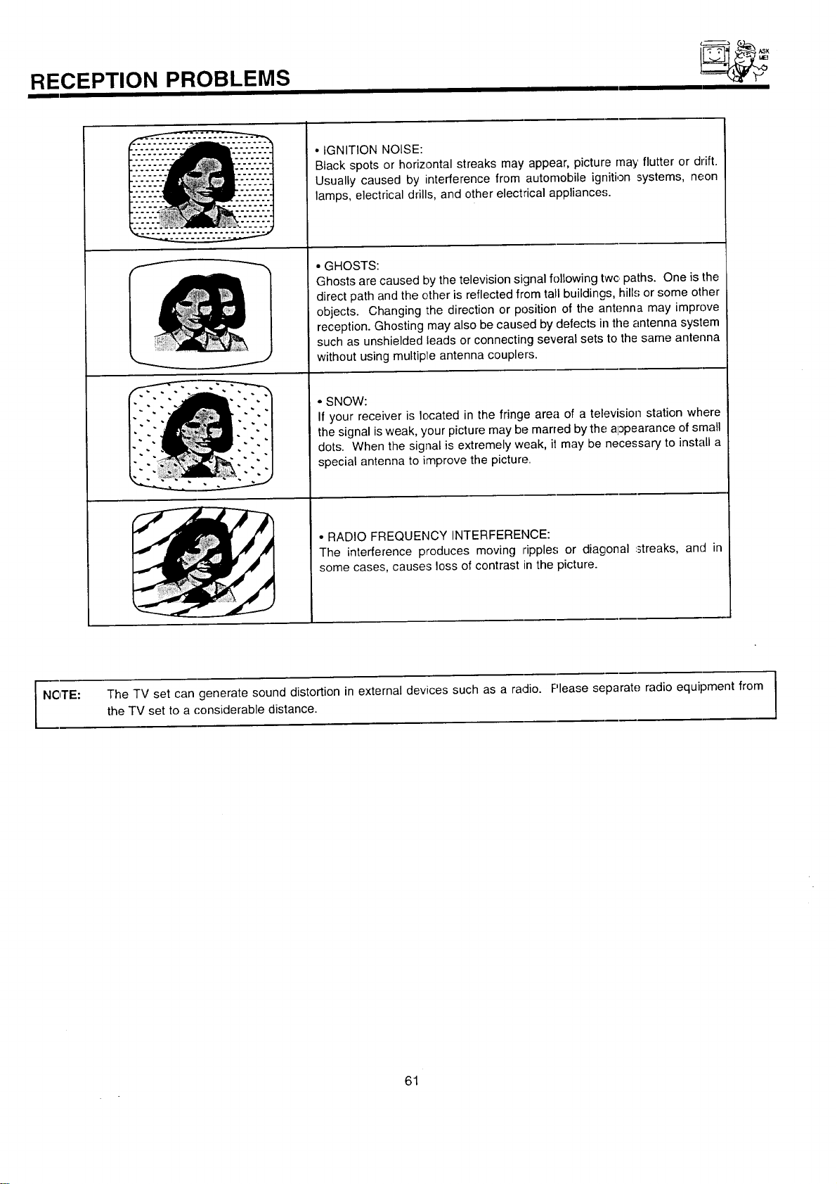
RECEPTION PROBLEMS
- _ ASK
• IGNITION NOISE:
Black spots or horizontal streaks may appear, picture may flutter or drift.
Usually caused by interference from automobile ignition systems, neon
lamps, electrical drills, and other electrical appliances.
• GHOSTS:
Ghosts are caused by the television signal following twc paths. One is the
direct path and the other is reflected from tall buildings, hill.'; or some other
objects. Changing the direction or position of the antenna may improve
reception. Ghosting may also be caused by defects in the antenna system
such as unshielded leads or connecting several sets to the same antenna
without using multipte antenna couplers.
• SNOW:
If your receiver is located in the fringe area of a television station where
the signal is weak, your picture may be marred by the a]3pearance of small
dots. When the signal is extremely weak, i! may be necessary to install a
special antenna to improve the picture.
• RADIO FREQUENCY INTERFERENCE:
The interference produces moving ripples or diagonal :streaks, and in
some cases, causes loss of contrast in the picture.
NOTE: The TV set can generate sound distortion in external devices such as a radio. Please separate radio equipment from I
I the TV set to a ('onsiderable distance.
I
61
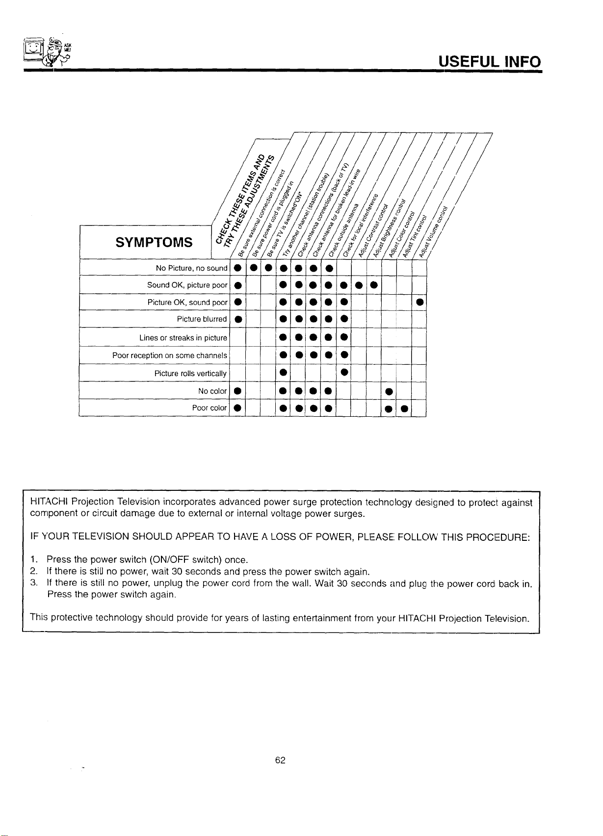
USEFUL INFO
SYMPTOMS
No Picture, nosound • • • • • • •
Sound OK, picture poor • • • • • • • •
Picture OK, sound poor • • • • • • •
Picture blurred • • • • • • !
Lines or streaks in picture • ! • • • •
Poor reception on some channels • I • • • •
Picture rolls vertically • •
NO color • I • • •!0 •
Poor color • • • 01 • •! •
I
HITACHI Projection Television incorporates advanced power surge protection technology designed to protect against
component or circuit damage due to external or internal voltage power surges.
IF YOUR TELEVISION SHOULD APPEAR TO HAVE A LOSS OF POWER, PLEASE FOLLOW THIS PROCIEDURE:
1. Press the power switch (ON/OFF switch) once.
2. If there is still no power, wait 30 seconds and press the power switch again.
3. If there is still no power, unplug the power cord from the wall. Wait 30 seconds and plug the power cord back in.
Press the power switch again.
This protective technology' should provide for years of lasting entertainment from your HITACHI Projection Television.
62
USI-FUL INFO
Features:
• Superfine Picture Quality
1000 Line Horizontal Resolution
• Pure Green and Red Filter Lenses
• Artificial Intelligence System
• Dolby Pro Logic*/Hall/Matrix 3-Stereo Surround Sound
• Remote (Controls many VCR brands, cable boxes, satellite boxes, and other audio equipment.)
• High Definition On-Screen Display (UltraTEC BIT-MAP)
• Full Set of Input Jacks, including S-Video
• Closed Caption Decoder
• Hkjh Resolution Picture-In-Picture with Freeze
• Tunes Port Bass Reflex Speakers
• Magic Focus (Auto Digital Convergence)
• Dual Antenna Inputs
• Auto Link
* "Dol_3y",the double-D symbol, and (where applicable) "Pro Logic" are trademarks of Dolby Laboratories Licensing Corporation.
Manufactured under license from Dolby Laboratories Licensing Corporation, Additionally licensed under one or more of the following
patents: U.S. number 3,959,590; Canada numbers 1,004,603 and 1,037,877. "Dolby", "Pro Logic", and the double-D symbol are trade-
marks of Dolby Laboratories Corporation.
Inputs: Outputs:
• Power Input .................. AC 120V, 60Hz • Video ...................... 1.0Vp-p. 75Ohm
Power Consumption (operating)
46UX50B/51K ........................ 153W
50UX52B/53K ........................ 153W
60UX54B/55K ........................ 153W
50SBX70B .......................... 183W
60SBX72B .......................... 183W
70SBX74B .......................... 183W
Power Consumption (maximum)
46UX50B/51 K ........................ 201W
50UX52B/53K ........................ 201W
60UX54B/55K ........................ 201W
5()SBX70B .......................... 260W
60SBX72B .......................... 260W
70SBX74B .......................... 260W
Antenna input impedance ............. 75 Ohm
Channel coverage .................... 181ch.
VHF-Band .......................... 2- 13
UHF-Band ......................... 14 - 69
CATV Mid Band ................... A-5 - A-1
................................ A-1
Super Band ........................... J-W
Hyper Band .................... W+I - W+28
Ultra Band .................... W+29 - W+84
Video ..................... 1.0Vp-p, 75 Ohm
S-Video
Luminance (Y) ............... 1.0Vp-p, 75 Ohm
Chrominance (C) ........... 0.286Vp-p, 75 Ohm
Audio input level ................... 47k Ohm
Dimensions:
Audio ................... 470mVrms, lk Ohm
46UX50B/51 K 50UX52B/53K
• Height (in.) 493/8 5113/16
• Width (in.) 401/8 433/16
• Depth (in.) 223/8 217/8
• Weight (Ibs.) 185 190
60UX54B/55K 50SBX70B
• Height (in.) 61 5113/16
• Width (in.) 5:2 433/8
• Depth (in.) 267/8 2411/16
• Weight (Ibs.) 30B 187
60SBX72B 70SBX74B
• Height (in.) 607/16 671/2
• Width (in.) 513/8 59
• Depth (in.) 263/8 301/4
• Weight (Ibs.) 288 385
* Average input level ................ 470mVrms
NOTE:
Due to improvements, specifications in this oper-
ating guide are subjecl to change without notice.
63

HITACHI
USEFUL INFO
To locate an authorized
HITACHI service facility
in the continental U.S.A.
and Canada,
DIAL TOLL FREE
7 days a week, 24 hours a day
(1-800-448-2244)
Hitachi Home Electronics (America), Inc.
I
Hitachi has made every effort to assure you hours of trouble free operation from your unit. However, should you require service,
a network of Hitachi Authorized Service Facilities has been established in all 50 states and Puerto Rico. Each facility will provide
you with convenient and expedient assistance. Our service hotline operator will direct you to the Hitachi Authorized Service
Facility nearest you. Just present proof of purchase and/or delivery receipts to the Hitachi Authorized Sc.rvice Facili[y, and ser-
vice will be rendered in accordance with the terms of the limited warranty as stated on your warranty care or operating guide.
Should you have any questions regarding warranty, service, operation, or technical assistance, please contact:
Hitachi Home Electronics (America), Inc.
3890 Steve Reynolds Blvd.
Norcross, GA 30093
Tel: 770-279-5600
Hitachi Sales Corporation of Hawaii
3219 Koapaka St.
Honolulu, HI 96819
"Tel:808-839-3621
For TVs purchased in Canada only, please contact one of the Hitachi offices below, should you have any ques-
tion:t regarding service, operation, or technical assistance.
MONTREAL
9425 Trans Canada
Saint-Laurent, Quebec
H4S 1V3
TORONTO
6740 Campobello Road
Mississauga, Ontario
L5N 2L8
VANCOUVER
20800 Westminster Hwy., Unit 1103
Richmond, B.C.
V6V 2W3
Tel: (514) 956-9882
Fax: (514) 956-9761
Tel: (905) 821-4545
Fax: (905) 826-6627
Tel. (60,$) 214-0777
Fax: I604) 214-0772
64

NOTES
65

NOTES
66

NOTES
67

HITACHI
QR21061