Operating and installation
instructions
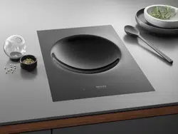
SmartLine downdraft extractor
To avoid the risk of accidents or damage to the appliance it is essen-
tial to read these instructions before it is installed and used for the
first time.
en-GB M.-Nr. 11 480 260

Contents
2
Warning and Safety instructions...................................................................... 4
Caring for the environment .............................................................................. 14
Guide to the appliance...................................................................................... 15
Downdraft extractor............................................................................................. 15
Controls and display ........................................................................................... 16
Accessories supplied .......................................................................................... 17
How it works ...................................................................................................... 18
Cleaning the SmartLine element for the first time ......................................... 19
Operation............................................................................................................ 20
Switching the downdraft extractor on ................................................................. 20
Setting/changing the power level........................................................................ 20
Switching the downdraft extractor off ................................................................. 20
Run-on time......................................................................................................... 20
Tips on saving energy ...................................................................................... 21
Cleaning and care ............................................................................................. 22
Cleaning the ceramic surface.............................................................................. 23
Cleaning the drip tray .......................................................................................... 23
Grease filter/extraction grille................................................................................ 24
Problem solving guide ...................................................................................... 26
Optional accessories ........................................................................................ 27
After sales service............................................................................................. 28
Contact in the event of a fault ............................................................................. 28
Data plate ............................................................................................................ 28
Warranty .............................................................................................................. 28
Installation.......................................................................................................... 29
Safety instructions for installation ....................................................................... 29
Installation examples........................................................................................... 30
Installation notes – surface-mounted.................................................................. 31
Worktop cutout – surface-mounted .................................................................... 33
Spacer bars – surface-mounted.......................................................................... 36
Installation dimensions–Surface-mounted........................................................ 37
Air duct dimensions – surface-mounted – worktop depth 600mm.................... 38
Air duct dimensions – surface-mounted – worktop depth greater than 600mm 41
Installation – surface-mounted............................................................................ 45
Installation notes – flush-fit ................................................................................. 52

Contents
3
Worktop cutout – flush-fit.................................................................................... 54
Spacer bars – flush-fit ......................................................................................... 57
Installation dimensions–Flush-fit ....................................................................... 58
Air duct dimensions – flush-fit – worktop depth 600mm ................................... 59
Air duct dimensions – flush-fit – worktop depth greater than 600mm ............... 62
Installation – flush-fit ........................................................................................... 66
Ducting ................................................................................................................ 73
Electrical connection ........................................................................................... 74
Product data sheets ......................................................................................... 75
Warning and Safety instructions
4
This downdraft extractor complies with all relevant safety require-
ments. Inappropriate use can, however, lead to personal injury and
material damage.
Please read these operating and installation instructions carefully
before using the downdraft extractor for the first time. They con-
tain important information on safety, installation, use and mainten-
ance. This prevents both personal injury and damage to the
downdraft extractor.
In accordance with standard IEC60335-1, Miele expressly and
strongly advises that you read and follow the instructions in the
chapter on installing the downdraft extractor as well as the safety
instructions and warnings.
Miele cannot be held liable for injury or damage caused by non-
compliance with these instructions.
Keep these instructions in a safe place and pass them on to any
future owner.
For safe operation, please also refer to the operating and installa-
tion instructions for the SmartLine elements and hob units installed
adjacent to the downdraft extractor.

Warning and Safety instructions
5
Correct application
This downdraft extractor is intended for use in domestic house-
holds and similar working and residential environments.
The downdraft extractor is not suitable for outdoor use.
It must only be used as a domestic appliance to extract vapours
and remove odours from cooking.
All other types of use are not permitted.
This downdraft extractor can only be used by people with reduced
physical, sensory or mental capabilities or lack of experience and
knowledge if they are supervised whilst using it.
They may only use the downdraft extractor unsupervised if they have
been shown how to use it in a safe manner. They must be able to re-
cognise and understand the consequences of incorrect operation.

Warning and Safety instructions
6
Safety with children
Children under 8 years of age must be kept away from the coun-
tertop extractor unless they are constantly supervised.
Children aged 8 and older may only use the countertop extractor
without supervision if they have been shown how to use it in a safe
manner. Children must be able to understand and recognise the pos-
sible dangers caused by incorrect operation.
Children must not be allowed to clean or maintain the downdraft
extractor unsupervised.
Children should be supervised in the vicinity of the downdraft ex-
tractor. Do not allow them to play with the downdraft extractor.
Danger of suffocation! Whilst playing, children may become en-
tangled in packaging material (such as plastic wrapping) or pull it
over their head with the risk of suffocation. Keep packaging material
away from children.

Warning and Safety instructions
7
Technical safety
Unauthorised installation, maintenance and repairs can cause
considerable danger for the user. Installation, maintenance and re-
pairs must only be carried out by a Miele authorised technician.
The downdraft extractor must only be installed and operated in
combination with those SmartLine elements and hob units specified
by Miele.
Damage to the downdraft extractor can compromise your safety.
Check it for visible signs of damage. Do not use a damaged
downdraft extractor.
Temporary or permanent operation on an autonomous power sup-
ply system or a power supply system that is not synchronised with
the mains power supply (e.g. island networks, back-up systems) is
possible. A prerequisite for operation is that the power supply sys-
tem complies with the specifications of EN50160 or an equivalent
standard.
The function and operation of the protective measures provided in
the domestic electrical installation and in this Miele product must
also be maintained in isolated operation or in operation that is not
synchronised with the mains power supply, or these measures must
be replaced by equivalent measures in the installation. As described,
for example, in the current version of BS OHSAS 18001–2 ISO
45001.
The electrical safety of the downdraft extractor can only be guar-
anteed when continuity is complete between it and an effective
earthing system. It is most important that this basic safety require-
ment is present and tested regularly. If in doubt, the electrical install-
ation should be checked by a qualified electrician.

Warning and Safety instructions
8
Before connecting the downdraft extractor to the mains supply,
ensure that the connection data on the data plate (voltage and fre-
quency) match the mains electricity supply. This data must corres-
pond in order to avoid the risk of damage to the downdraft extractor.
Compare this data before connecting the appliance to the mains.
Consult a qualified electrician if in any doubt.
Multi-socket adapters and extension leads do not guarantee the
required safety of the appliance (fire hazard). Do not use these to
connect the downdraft extractor to the mains electricity supply.
For safety reasons, this downdraft extractor may only be used
after it has been built in.
This downdraft extractor must not be installed and operated in
mobile installations (e.g. on a ship).
Any contact with live connections or tampering with the electrical
or mechanical components of the downdraft extractor will endanger
your safety and may lead to appliance malfunctions.
Only open the casing as described in the installation instructions and
in the “Cleaning and care” section of this booklet. Under no circum-
stances should any other parts of the casing be opened.
The manufacturer's warranty will be invalidated if the downdraft
extractor is not repaired by a Miele approved service technician.
Miele can only guarantee the safety of the appliance when genu-
ine original Miele replacement parts are used. Faulty components
must only be replaced by Miele spare parts.
The downdraft extractor is not intended for use with an external
timer switch or a remote control system.
If the plug is removed from the connection cable or if the cable is
supplied without a plug, the downdraft extractor must be connected
to the electrical supply by a suitably qualified electrician.

Warning and Safety instructions
9
If the mains connection cable is damaged, it must be replaced
with a special mains connection cable by a qualified electrician (see
“Electrical connection” in the “Installation” chapter).
During installation, maintenance and repair work, the downdraft
extractor must be completely disconnected from the mains electri-
city supply. It is only completely isolated from the electricity supply
when:
- the mains fuse has been disconnected or
- the screw-out fuses have been fully unscrewed or
- the plug (if present) is removed from the socket. To do this, pull
the plug not the mains connection cable.
Warning and Safety instructions
10
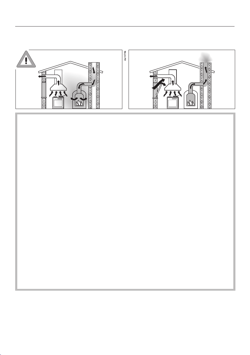
Using at the same time as other heating appliances that depend on the air
from the room
Danger of toxic fumes!
Great care should be taken when using the downdraft extractor in
the same room or the same area of the house as another heating
appliance that depends on the air from the room.
Such heating appliances draw in air from the room and duct ex-
haust gases out through a chimney or extraction ducting. They in-
clude gas, oil, wood and coal-fired boilers and heaters, continuous
flow or other water heaters, gas hobs and ovens.
The downdraft extractor draws in air from the kitchen and from
neighbouring rooms. This applies to the following modes of opera-
tion:
- extraction mode,
- recirculation mode with a recirculation box installed outside the
room.
If there is insufficient air, an underpressure will occur. The heating
appliance may be starved of oxygen. This impairs combustion.
Harmful gases could be drawn from the chimney or extraction
ducting back into the room.
This could have potentially fatal consequences!

Warning and Safety instructions
11
In order to ensure safe operation and to prevent gases given off by
the heating appliance from being drawn back into the room, when
the downdraft extractor and the heater are both operated simultan-
eously, an underpressure in the room of 0.04mbar (4Pa) is the
maximum permissible.
Sufficient ventilation can be maintained by air inlets which cannot
be blocked, e.g. in windows, doors and outside wall vents. The
diameter of the inlet openings must enable sufficient ventilation. A
ventilation brick alone is not generally sufficient to ensure safe
ventilation.
The overall ventilation condition of the dwelling must be taken into
account. If in any doubt, the advice of a competent builder, or for
gas, a qualified gas fitter should be sought.
If the downdraft extractor is being operated in recirculation mode,
where the air is directed back into the room in which it is located,
operating a heating appliance which depends on the room air at
the same time is not hazardous.

Warning and Safety instructions
12
Correct use
Open flames are a fire hazard.
Never use an open flame beside the downdraft extractor. To avoid
the danger of fire, do not flambé or grill over an open flame. When
switched on, the downdraft extractor could draw flames into the fil-
ter. Fat deposits could ignite, presenting a fire hazard.
Overheated oil and fat can ignite, causing fire damage to the
downdraft extractor.
When cooking with oil or fat, chip pans and deep fat fryers, etc, do
not leave the pots and pans unattended. Similarly, never leave an
open grill unattended when grilling.
Deposits of grease and dirt will prevent the downdraft extractor
from working properly.
Do not use the downdraft extractor without the grease filters in
place. Otherwise cooking vapours will not be cleaned.
Hot cooking vapours during cooking can cause the downdraft ex-
tractor to get hot.
Do not touch the casing or the grease filters until the downdraft ex-
tractor has cooled down.
Do not use the downdraft extractor for resting objects on.
Liquids can damage the downdraft extractor if they get into it.
Keep liquids away from the downdraft extractor.
Light objects can be drawn into the downdraft extractor and im-
pair its operation.
Do not place any light objects (e.g. paper towels) within close prox-
imity of the downdraft extractor.
If you are operating a gas cooking element directly next to the
downdraft extractor, the FlameGuard must be placed between the
downdraft extractor and the element.

Warning and Safety instructions
13
Cleaning and care
The steam from a steam cleaning appliance could reach live elec-
trical components and cause a short circuit.
Do not use a steam cleaner to clean the downdraft extractor.
There is a risk of fire if the cooker hood is not cleaned as de-
scribed in these operating instructions.
Miele will guarantee to supply functional spare parts for a min-
imum of 10years and up to 15years following the discontinuation of
your CombiSet.
Accessories
Only use genuine original Miele accessories and spare parts with
this appliance. Using accessories or spare parts from other manu-
facturers will invalidate the warranty and Miele cannot accept liabil-
ity.

Caring for the environment
14
Disposal of the packing mater-
ial
The packaging is designed to protect
the appliance from damage during
transportation. The packaging materials
used are selected from materials which
are environmentally friendly for disposal
and should be recycled.
Recycling the packaging reduces the
use of raw materials in the manufactur-
ing process and also reduces the
amount of waste in landfill sites.
Disposing of your old appli-
ance
Electrical and electronic appliances of-
ten contain valuable materials. They
also contain specific materials, com-
pounds and components, which were
essential for their correct function and
safety. These could be hazardous to hu-
man health and to the environment if
disposed of with your domestic waste
or if handled incorrectly. Please do not,
therefore, dispose of your old appliance
with your household waste.
Please dispose of it at your local com-
munity waste collection / recycling
centre for electrical and electronic ap-
pliances, or contact your dealer or
Miele for advice. You are also respons-
ible for deleting any personal data that
may be stored on the appliance being
disposed of. Please ensure that your
old appliance poses no risk to children
while being stored prior to disposal.
Guide to the appliance
15
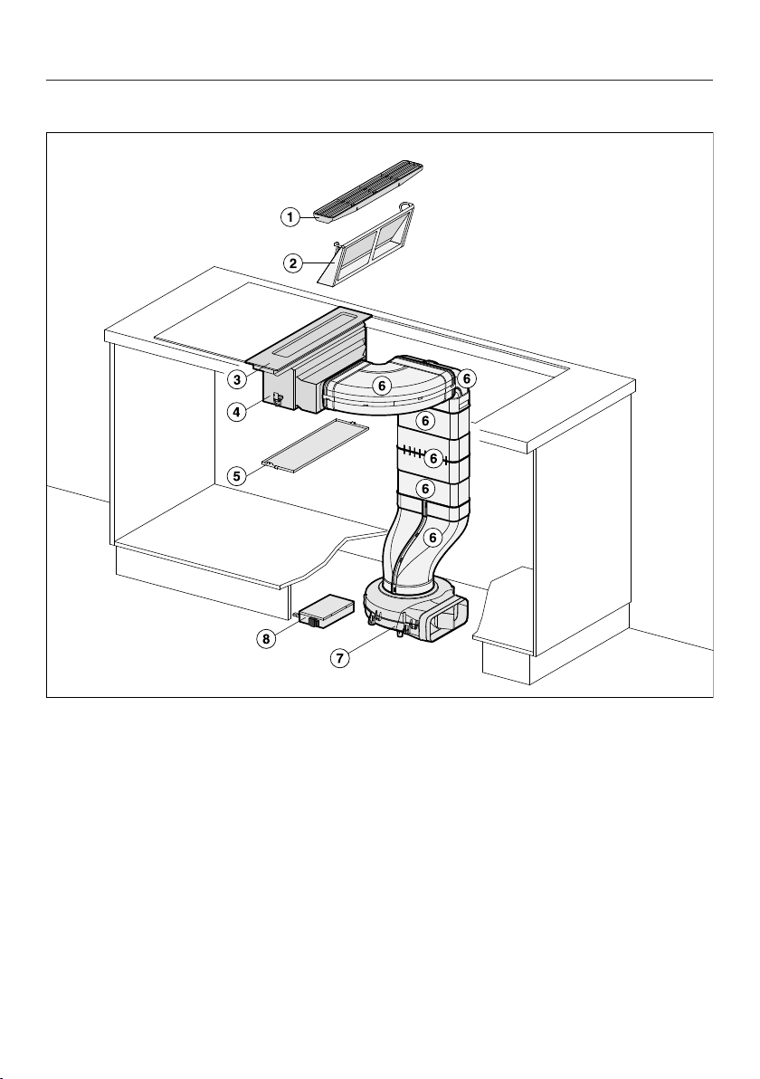
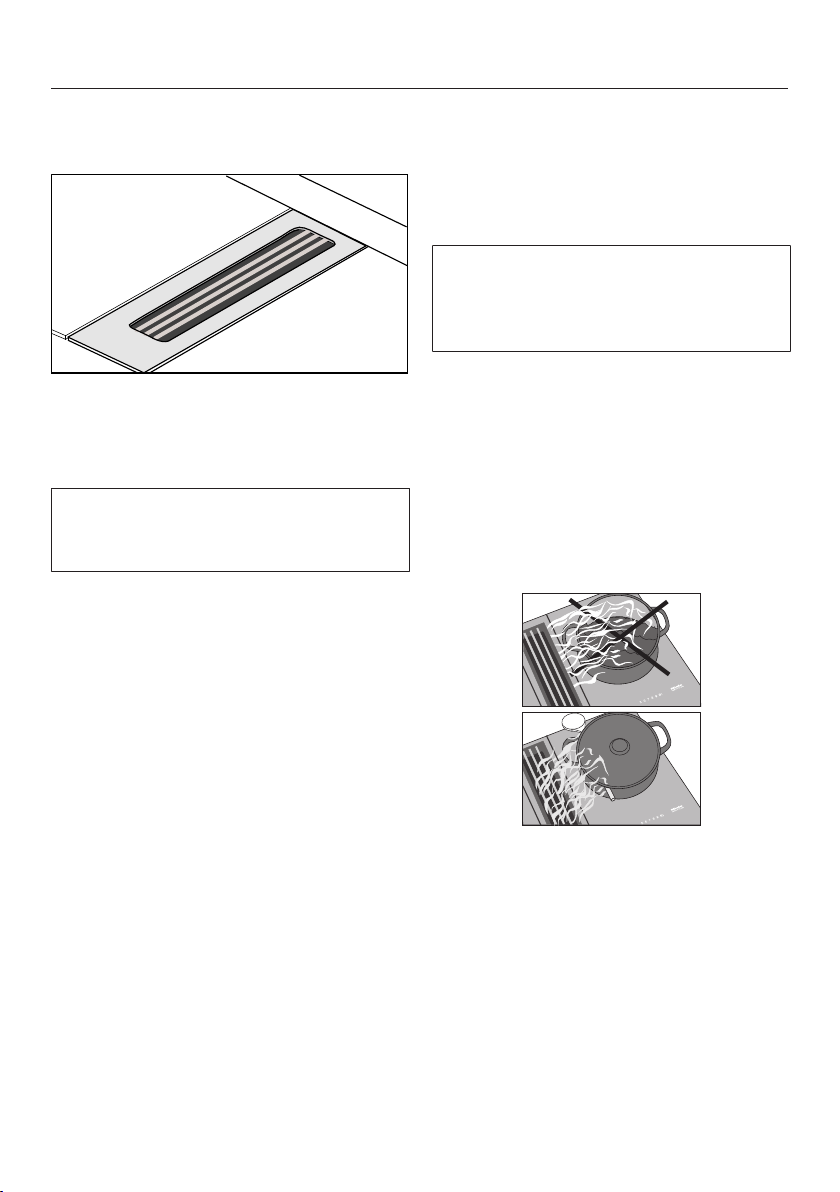
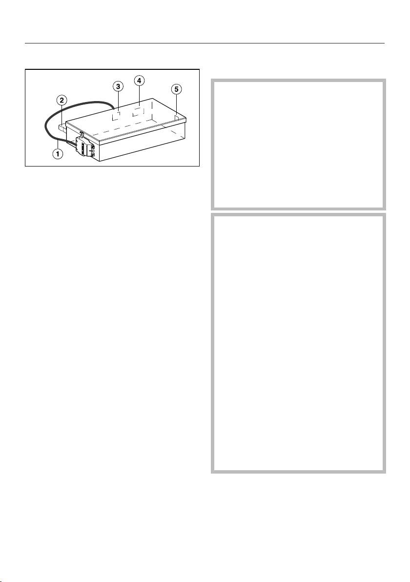
Downdraft extractor
a
Extraction grille
b
Grease filter
c
Cover with control unit
d
Casing
e
Removable drip tray
f
Air duct
(supplied as accessory)
g
Fan
In the plinth on the floor
h
E-box
Guide to the appliance
16
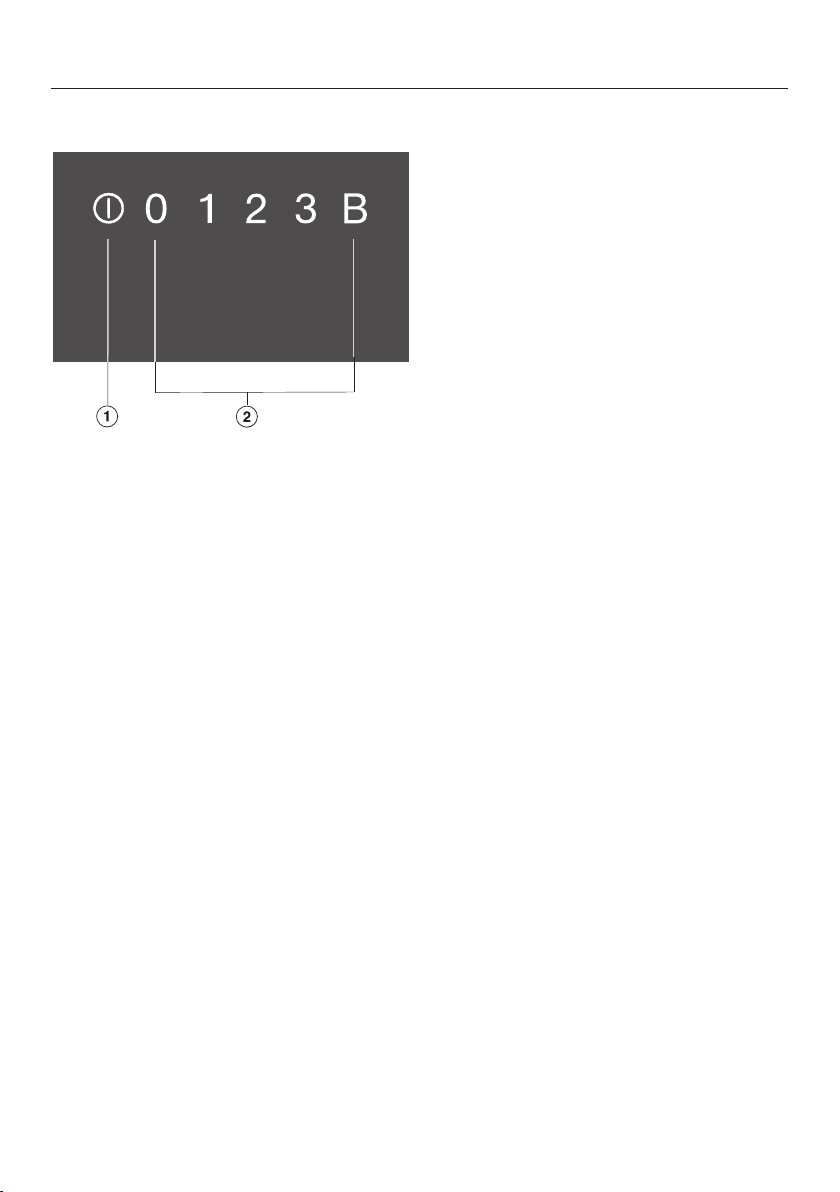
Controls and display
a
Countertop extractor On/Off
b
Numerical display
To set a power level

Guide to the appliance
17
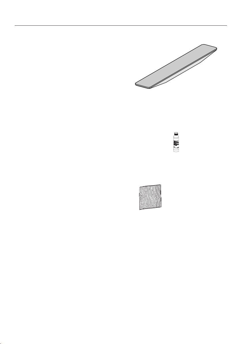
Accessories supplied
The accessories supplied with your ap-
pliance as well as a range of optional
ones are available to order from Miele
(see “Optional accessories”).
Air duct
Flat ducting system for routing air from
the casing to the fan.

How it works
18
Extraction mode
The air is drawn in and cleaned by the
grease filter and directed outside.
Recirculation mode
(DUU 1000(-1) conversion kit required)
The air is drawn in and cleaned by the
grease filter. The air is then directed into
the recirculation box where it is also
cleaned by the charcoal filters. The
cleaned air is then recirculated back
into the kitchen.

Cleaning the SmartLine element for the first time
19
Please stick the extra data plate for
the appliance supplied with this doc-
umentation in the space provided in
the “After sales service” section of
this booklet.
Remove any protective wrapping and
stickers.
Clean the ceramic surface with a
damp cloth, and then wipe dry.
Operation
20
Switching the downdraft ex-
tractor on
Insert the extraction grille.
Touch the sensor control.
The sensor controls light up.
If no further entry is made, the
downdraft extractor will switch itself
off after a few seconds.
Setting/changing the power
level
For light to heavy cooking vapours and
odours, select from power levels 1 to 3.
For short periods of cooking food with
intensive vapours and a strong aroma,
e.g. when searing meat, select Booster
setting B.
Touch the desired power level.
Booster
The maximum duration for the Booster
is 10minutes.
To switch it off early, set a different
power level.
Switching the downdraft ex-
tractor off
Touch the sensor control.
The sensor controls go out.
If the downdraft extractor is not
switched off, it will switch itself off
12hours after the last automatic oper-
ation.
Run-on time
In order to rid kitchen air of steam and
odours, the downdraft extractor contin-
ues to run for 5minutes on the power
level that was set last. The power level
is gradually reduced during the run-on
time. The current power level pulsates
during the run-on time.
Tip: To help release vapours effectively
with pans over 15cm high, place a
wooden spoon between the lid and the
pot.

Tips on saving energy
21
This downdraft extractor operates very
efficiently and economically. The follow-
ing will help you to save even more en-
ergy when using it:
- It is important to ensure that the kit-
chen is well ventilated during opera-
tion. In extraction mode if there is in-
sufficient air flow, the downdraft ex-
tractor cannot operate efficiently and
this causes increased operating noise
levels.
- Always cook with the lowest possible
setting. This produces fewer cooking
vapours, so you can use a lower
power level and therefore benefit
from reduced energy consumption.
- Check the selected power level on
the downdraft extractor. A low power
level is usually sufficient. Only use the
Booster setting when necessary.
- When a large volume of cooking va-
pours are being produced, switch to
a high power level in good time. This
is more efficient than operating the
downdraft extractor for longer to try
to capture cooking vapours which
have already been distributed
throughout the kitchen.
- Switch the downdraft extractor off
after cooking.
- Clean or replace the filters at regular
intervals. Heavily soiled filters reduce
performance, increase the risk of fire
and are unhygienic.

Cleaning and care
22
Danger of burning due to hot
surfaces.
The surfaces will be hot after cook-
ing.
Switch the countertop extractor and
the cooking elements off.
Allow the surfaces to cool down be-
fore cleaning the countertop ex-
tractor.
Risk of damage due to moisture
ingress.
The steam from a steam cleaning ap-
pliance could reach live electrical
components and cause a short cir-
cuit.
Do not use a steam cleaner to clean
the countertop extractor.
All surfaces could be discoloured or
damaged if unsuitable cleaning
agents are used. All surfaces are
susceptible to scratching.
Remove all cleaning agent residues
immediately.
Never use abrasive sponges or
cleaning agents.
Allow the SmartLine element to cool
down before cleaning.
Clean the SmartLine element and ac-
cessories after each use.
Dry the SmartLine element thoroughly
after every cleaning to avoid limes-
cale residue.
Unsuitable cleaning agents
To avoid damaging the surfaces of the
appliance, do not use:
- washing-up liquid
- cleaning agents containing soda, al-
kalines, ammonia, acids or chlorides
- cleaning agents containing descaling
agents
- stain and rust removers
- abrasive cleaning agents, e.g.
powder cleaners and cream cleaners
- solvent-based cleaning agents
- dishwasher cleaner
- oven sprays
- glass cleaning agents
- hard, abrasive brushes or sponges
(e.g. pot scourers) or sponges which
have been previously used and still
contain abrasive cleaning agents
- melamine eraser blocks
Cleaning and care
23
Cleaning the ceramic surface
Risk of damage by pointed ob-
jects.
The seal between the SmartLine ele-
ment and the worktop could suffer
damage.
Do not use pointed objects for clean-
ing.
Not all soiling and residues can be
removed using a solution of wash-
ing-up liquid. An invisible film can
develop that can lead to discoloura-
tion of the glass ceramic surface.
This discolouration cannot be re-
moved.
Clean the ceramic surface regularly
with a proprietary ceramic glass
cleaning agent.
Remove any coarse soiling with a
damp cloth and more stubborn soil-
ing with a shielded scraper blade
suitable for use on glass.
Then clean the ceramic glass surface
with the Miele ceramic and stainless
steel hob cleaner (see “optional ac-
cessories”) or with a proprietary
ceramic glass cleaner applied with
kitchen paper or a clean cloth. Please
follow the cleaning agent manufac-
turer's instructions.
Clean the ceramic surface with a
damp cloth, and then wipe dry. En-
sure that all cleaning agent residues
are removed.
Spots caused by limescale and water
residues can be removed using
Miele's ceramic and stainless steel
hob cleaner.
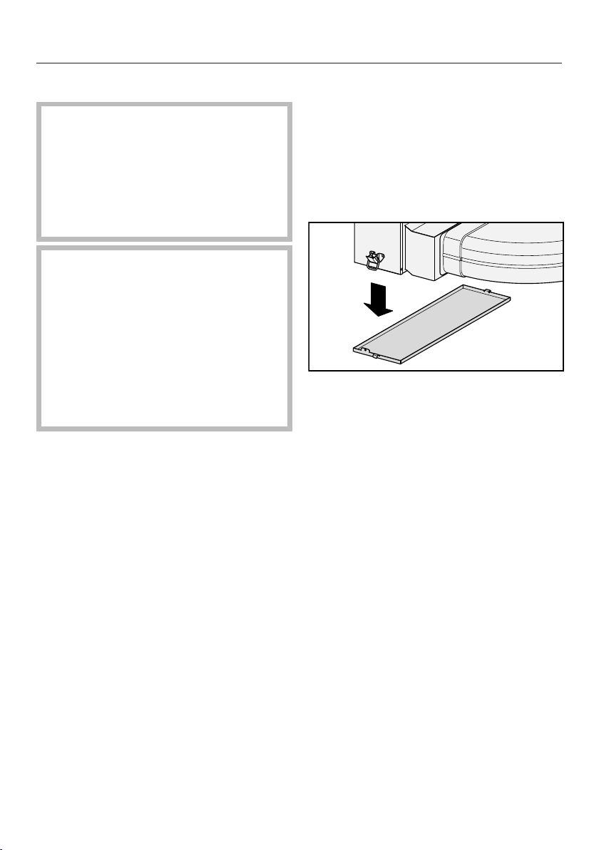
Cleaning the drip tray
Clean the drip tray if liquids have boiled
over or spilled into the countertop ex-
tractor.
Remove and clean the grease filter as
described in the “Grease filter” sec-
tion.
Hold the drip tray and open the 2
clips (1xfront, 1xrear). Carefully re-
move the drip tray from the casing,
making sure it is kept horizontal.
Pour out the liquid.
Clean and dry the drip tray.
Clean and dry the accessible inside
of the countertop extractor.
Fasten the drip tray back onto the
casing.
Replace the grease filter and the
cover on top.
Cleaning and care
24
Grease filter/extraction grille
The extraction grille and the reusable
metal grease filter in the vapour extrac-
tion fan collect solid matter from kit-
chen vapours (grease, dust, etc.) and
therefore prevent soiling of the
downdraft extractor. Accumulated
grease solidifies over a longer period of
time and makes cleaning more difficult.
The grease filter should therefore be
cleaned at least every 3–4weeks.
Risk of fire due to soiled grease
filter.
Grease collected in the grease filter
can ignite.
Clean the grease filter regularly.
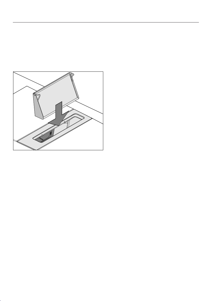
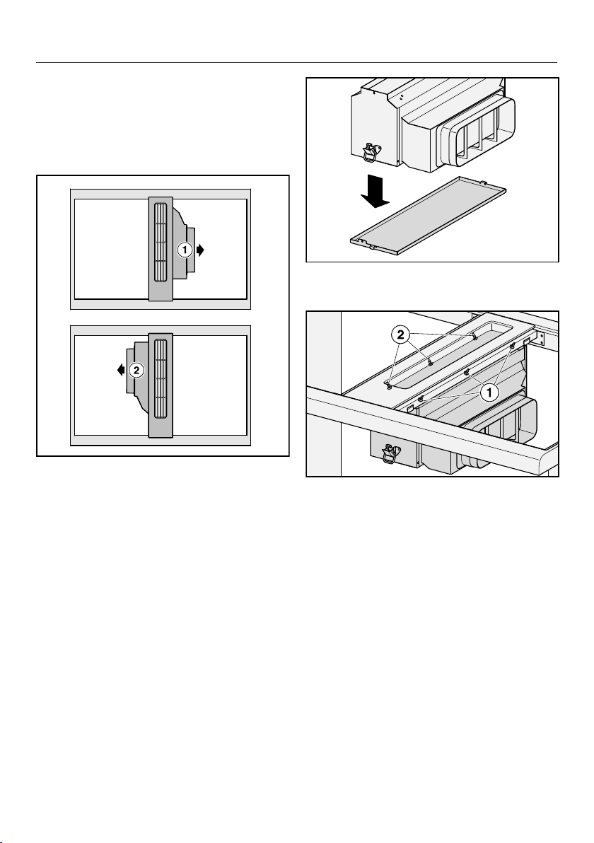
Removing the grease filter
Remove the FlameGuard if neces-
sary.
Lift up the extraction grille.
Carefully remove the grease filter. En-
sure that you do not tilt the grease fil-
ter.
Pour out any liquid which has collec-
ted at the bottom of the grease filter.
Cleaning the extraction grille and the
grease filter by hand
Clean the extraction grille and the
grease filter with a soft nylon brush in
a mild solution of hot water and a
little washing-up liquid. Do not use
concentrated washing-up liquid.
Cleaning the extraction grille and the
grease filter in the dishwasher
Place the extraction grille upright in
the lower basket.
Place the grease filter with its base
facing upwards in the lower basket.
Ensure the spray arm is not obstruc-
ted.
Use a standard household dish-
washer detergent.
Select a dishwasher programme with
a maximum wash temperature of:
- 55°C for the extraction grille
- 65°C for the grease filter
Depending on the detergent used,
cleaning the grease filter in a dish-
washer can cause permanent discol-
ouration to the internal surfaces of the
filter. However, this will not affect the
functioning of the grease filter in any
way.
Cleaning and care
25
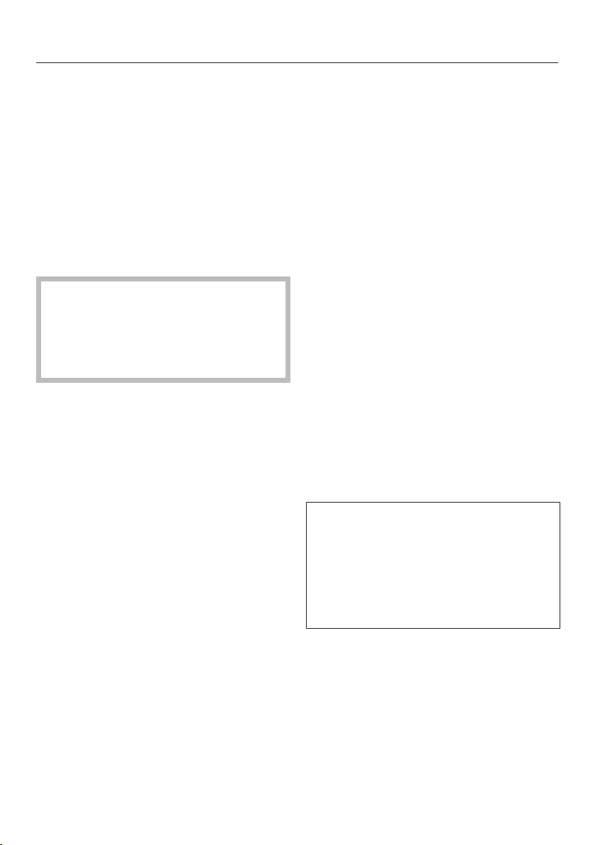
Fitting the grease filter
Fit the grease filter so that the straight
side of the grease filter is on the side
that connects to the air duct.
Example: connector for air duct on the
left
Interior of the casing
When removing the grease filter for
cleaning, also clean off any access-
ible oil or fat build-up from the cas-
ing. Doing so will prevent a fire haz-
ard.
Problem solving guide
26
Many malfunctions and faults that can occur in daily operation can be easily
remedied. Time and money will be saved because a service call will not be
needed.
The following guide may help you to find the reason for a malfunction or a fault,
and to correct it.
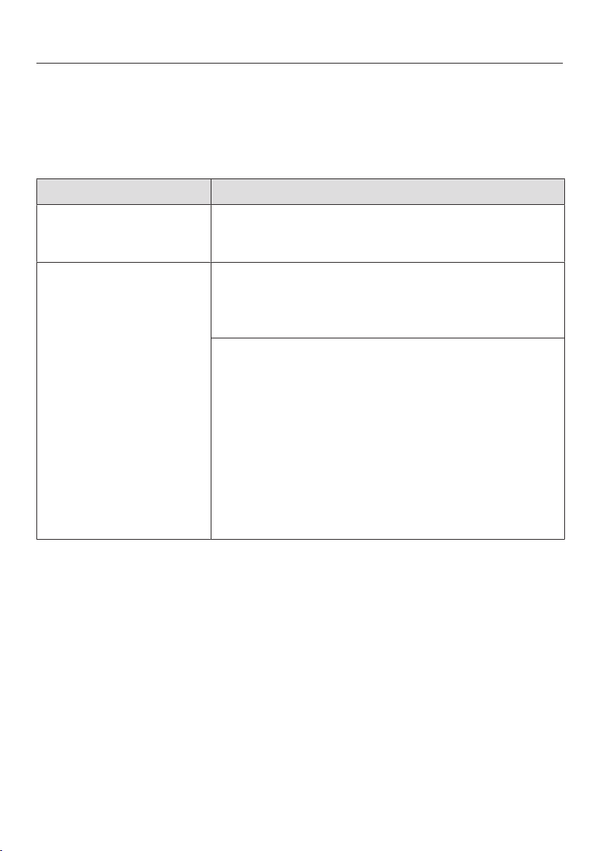
Problem Cause and remedy
The power levels 1 to B
light up one after the
other.
An automatic reset is performed after an interrup-
tion to the power supply.
The SmartLine element
cannot be switched on.
There is no power to the SmartLine element.
Check whether the mains fuse has tripped. Con-
tact an electrician or Miele Service (for the min-
imum fuse rating, see data plate).
There may be a technical fault.
Disconnect the SmartLine element from the mains
electricity supply for approx. 1 minute by
– tripping the relevant mains fuse or screwing the
fuse out completely, or
– switching off the residual current protection
device.
If, after resetting the trip switch in the mains fuse
box or the residual current protection device, the
SmartLine element will still not switch on, contact
a qualified electrician or Miele Service.
Optional accessories
27
Miele offer a comprehensive range of
useful accessories as well as cleaning
and conditioning products for your
Miele appliances.
These products can be ordered through
the Miele Webshop.
They can also be ordered from Miele
(see end of this booklet for contact de-
tails) or from your Miele dealer.
FlameGuard
For installing between the downdraft
extractor and a gas cooking element
Ceramic and stainless steel
hob cleaner 250ml
Removes heavy soiling, limescale de-
posits and aluminium residues
Microfibre cloth
Removes finger marks and light soiling

After sales service
28
Contact in the event of a fault
In the event of any faults which you cannot remedy yourself, please contact your
Miele dealer or the Miele Customer Service Department.
You can book a Miele Customer Service Department call-out online at
www.miele.com/service.
Contact information for the Miele Customer Service Department can be found at
the end of this document.
Please quote the model identifier and serial number of your appliance (Fabr./SN/
Nr.) when contacting the Miele Customer Service Department. This information
can be found on the data plate.
Please note that telephone calls may be monitored and recorded for training pur-
poses and that a call-out charge will be applied to service visits where the problem
could have been resolved as described in this booklet.
Data plate
Stick the extra data plate supplied with the appliance here. Make sure that the
model number matches the one specified on the back cover of this document.
Warranty
For information on the appliance warranty specific to your country please contact
Miele. See back cover for address.
In the UK, your appliance warranty is valid for 2 years from the date of purchase.
However, you must activate your cover by calling 0330 160 6640 or registering on-
line at www.miele.co.uk.

Installation
*INSTALLATION*
29
Safety instructions for installation
Damage risk from incorrect installation.
Incorrect installation can cause damage to the SmartLine element.
The SmartLine element must only be installed by a qualified person.
Damage from falling objects.
Take care not to damage the SmartLine element when fitting wall units above it.
Fit the wall units before the SmartLine element.
After installation, the mains connection cable of the SmartLine
element must not come into contact with any moving kitchen com-
ponent (e.g. a drawer) or be subject to mechanical loads which could
damage it.
Combination with gas appliances
Only Miele CS 7xxx gas appliances may be installed next to the
downdraft extractor.
Observe carefully the safety clearances listed on the following
pages.
Exhaust ducting must be of non-inflammable material. Suitable
material is available from Miele specialist dealers or the Miele Spares
Dept.
The appliance must not be connected to a chimney or flue which
is in use. Neither should it be connected to ducting which ventilates
rooms with fireplaces.
If exhaust air is to be extracted into a chimney or ventilation duct
no longer used for other purposes, seek professional advice.

Installation
*INSTALLATION*
30
Installation examples
Recirculation mode
Extraction mode

Installation
*INSTALLATION*
31
Installation notes –
surface-mounted
Sealing between the SmartLine Ele-
ment and the worktop
The SmartLine element and worktop
may be damaged if the element
needs to be removed after it has
been sealed with a sealant.
Do not use any sealant between the
SmartLine element and the worktop.
The seal under the edge of the top
part of the appliance provides a suf-
ficient seal for the worktop.
Tiled worktop
Grout lines and the hatched area un-
derneath the SmartLine element frame
must be smooth and even. If they are
not, the SmartLine element will not sit
flush with the worktop and the sealing
strip underneath the top part of the ap-
pliance will not provide a good seal
between the appliance and the work-
top.
Sealing strip
Dismantling the SmartLine element
for service purposes may damage
the sealing strip underneath the edge
of the SmartLine element.
Always replace the sealing strip be-
fore reinstalling the SmartLine ele-
ment.

Installation
*INSTALLATION*
32
Installing several
SmartLine elements
The gaps between the individual Smart-
Line elements are sealed with a silicone
sealant that is heat-resistant to at least
160°C. With flush-fit installation, the
gap between the SmartLine element(s)
and the worktop must also be sealed
with a silicone sealant that is heat-res-
istant to at least 160°C.
After installation, the SmartLine ele-
ments must be easily accessible from
below, so that the bottom half of the
casing can be removed for mainten-
ance. If the SmartLine elements are not
accessible from below, the sealant must
be removed so that they can be re-
moved.
Worktop depth
The downdraft extractor can be in-
stalled with the connector for the air
duct on either the right or the left-hand
side.
Minimum worktop depth for
- Right connector 600mm
- Left connector 665mm
Installation
*INSTALLATION*
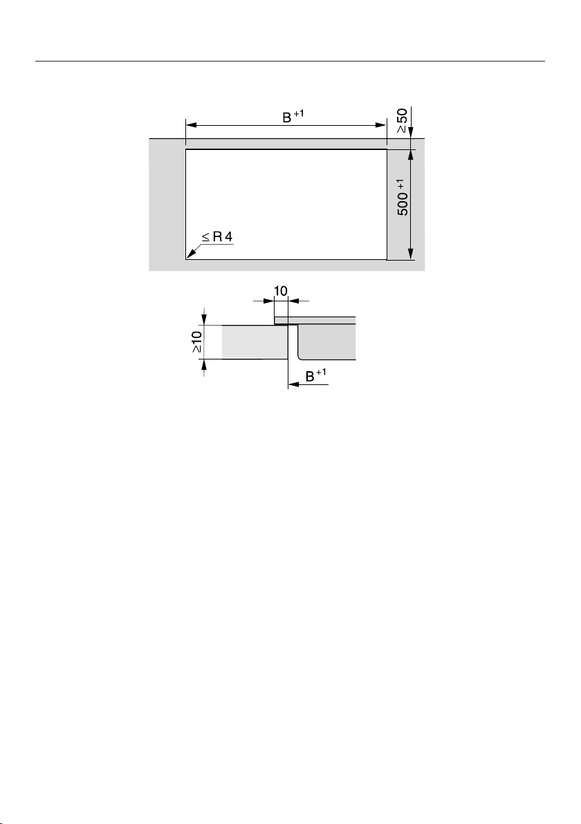
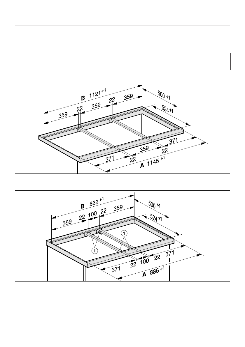
33
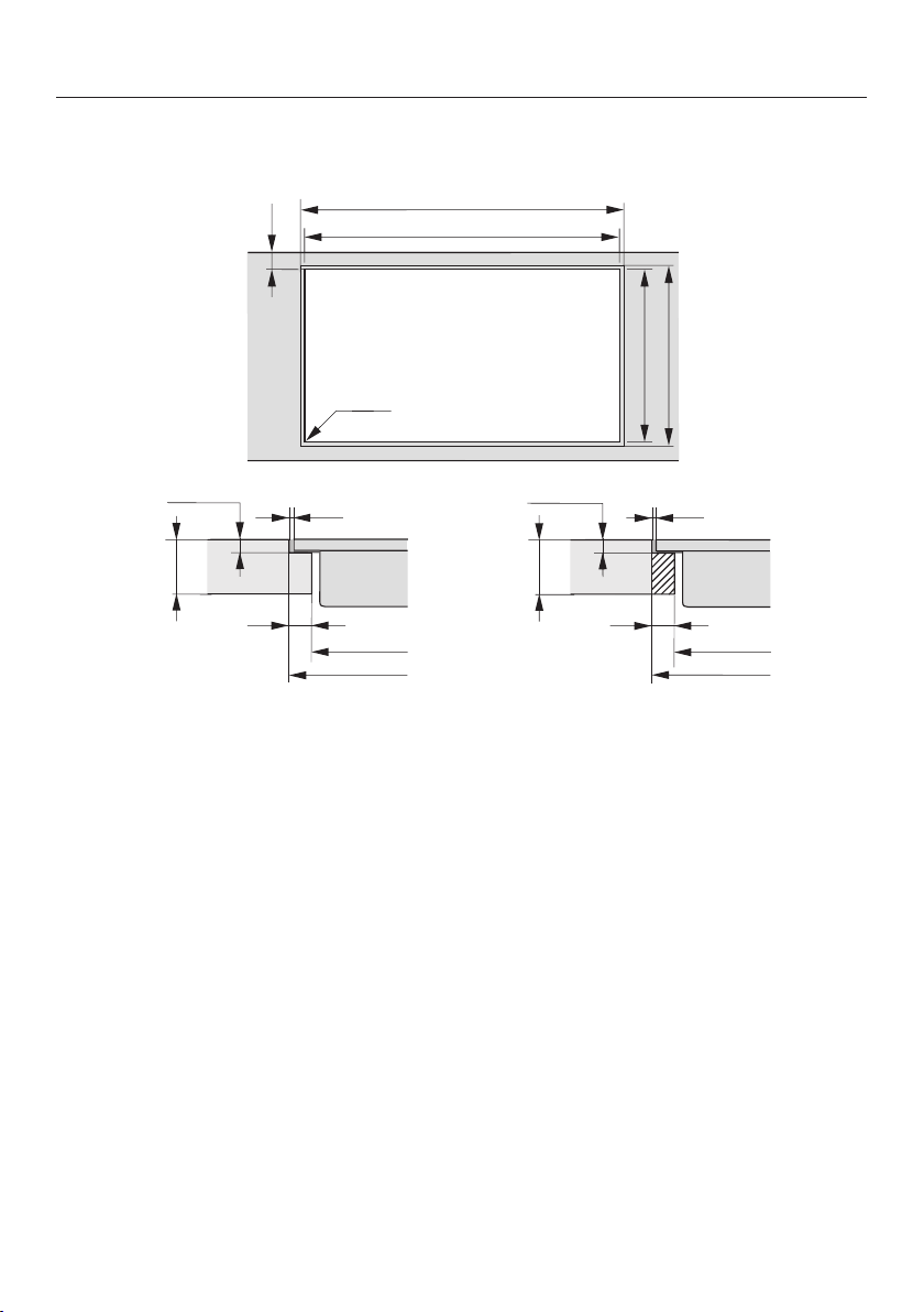
Worktop cutout – surface-mounted
Installation
*INSTALLATION*
34
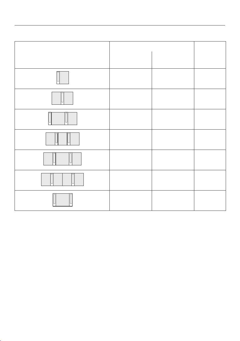
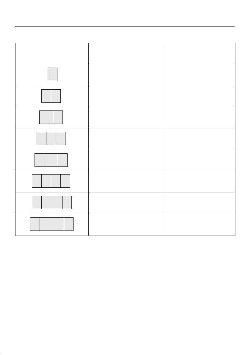
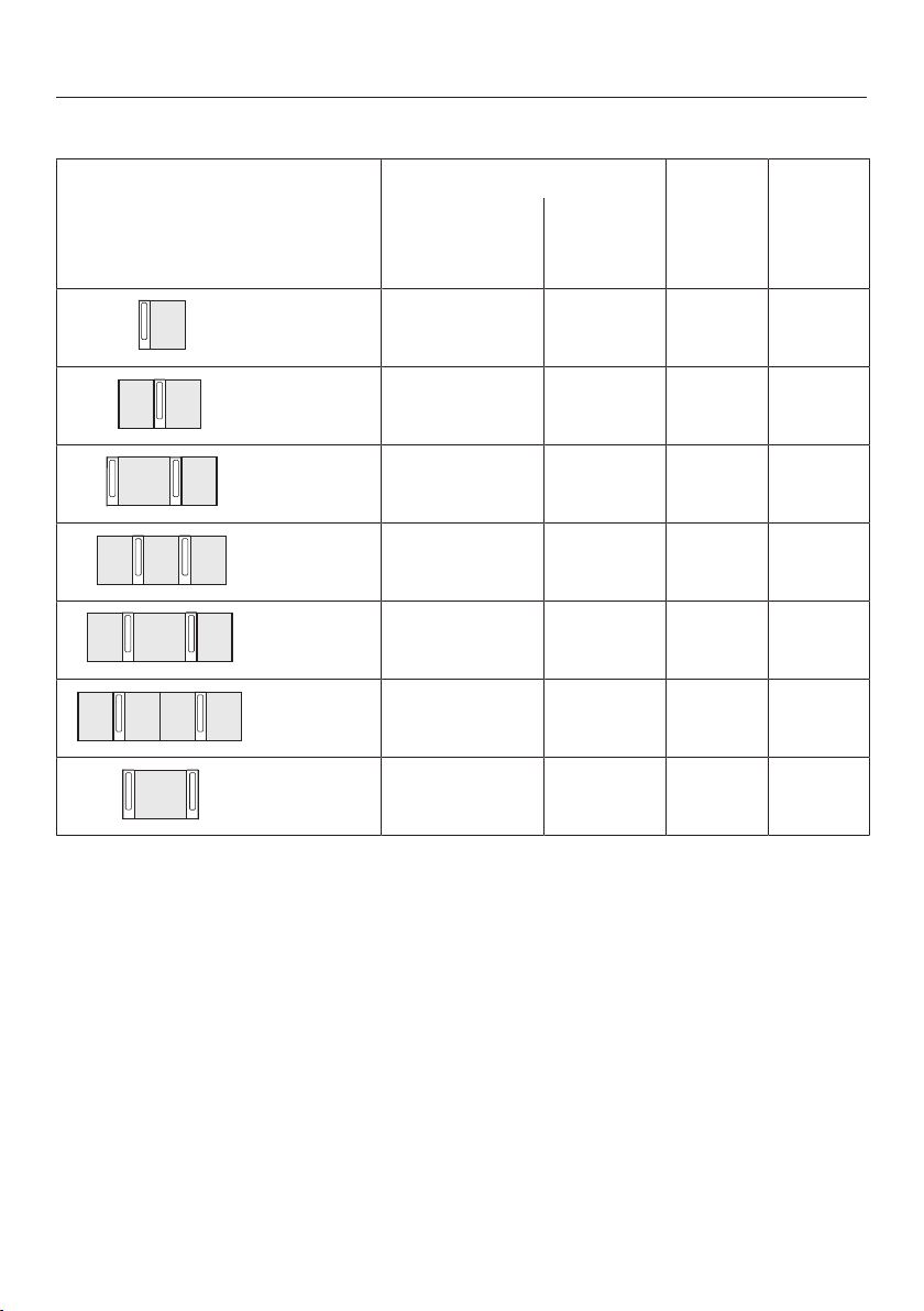
Installation with a countertop extractor
Combination examples Numberxwidth [mm] Dimen-
sionB
[mm]
Cooking ele-
ments
Countertop
extractor
1x378 1x120 481
2x378 1x120 862
1x378
1x620
2x120 1226
3x378 2x120 1365
2x378
1x620
2x120 1607
4x378 2x120 1746
1x620 2x120 845
Installation
*INSTALLATION*
35
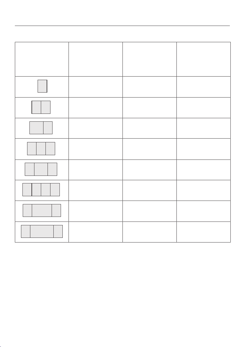
Installation without a countertop extractor
Combination examples Numberxwidth [mm] DimensionB
[mm]
Cooking elements
1x378 359
2x378 740
1x378
1x620
982
3x378 1121
2x378
1x620
1363
4x378 1502
2x378
1x800
1554
2x378
1x936
1680
Installation
*INSTALLATION*
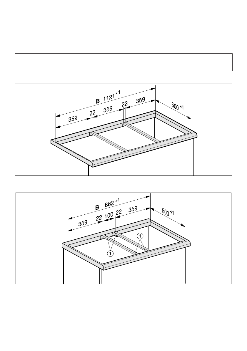
36
Spacer bars – surface-mounted
If you are installing several appliances, you must fit spacer bars between them.
The clips supplied with the spacer bars are only required for installing a
CSDA700xFL.
Installing 3elements and 2spacer bars
Spacer bars for the downdraft extractor – surface-mounted
a
Brackets
Installation
*INSTALLATION*
37
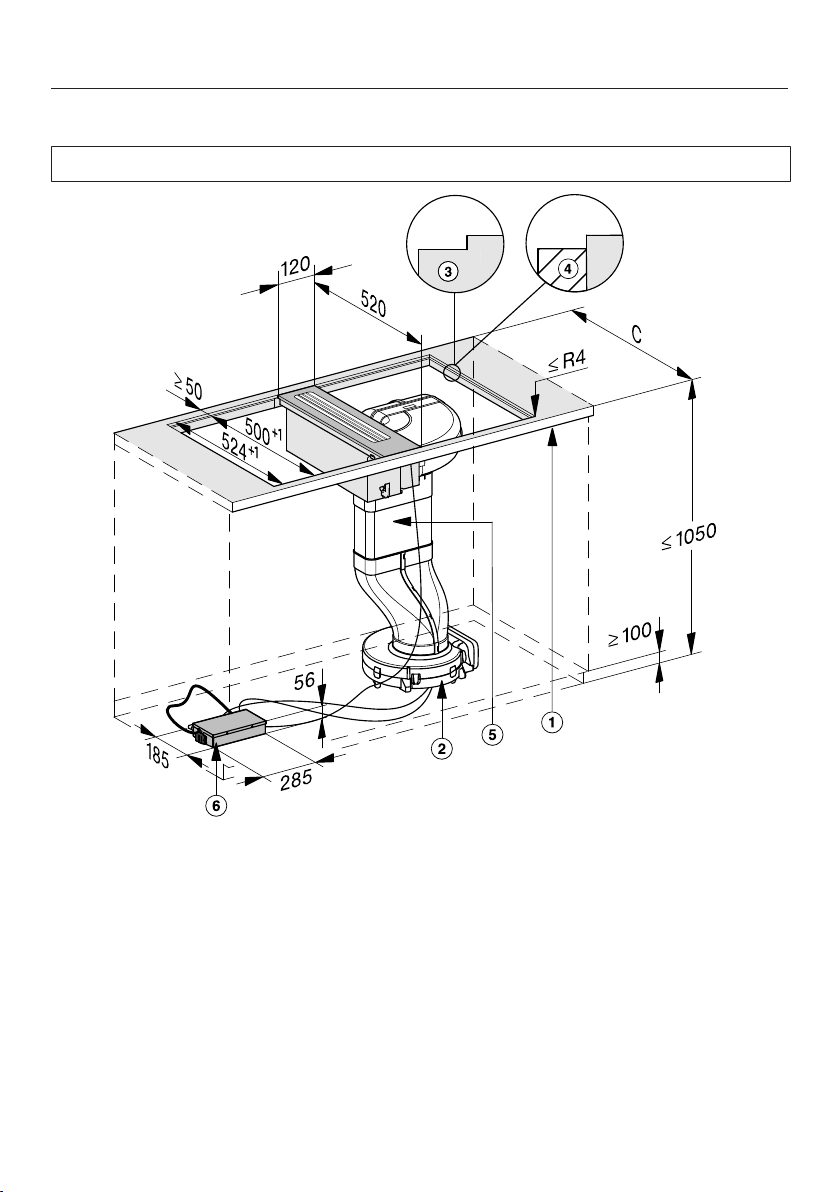
Installation dimensions–Surface-mounted
All dimensions are given in mm.
a
Front
b
Fan
In the plinth on the floor
c
Air duct
(supplied as accessory)
d
E-box
Installation
*INSTALLATION*
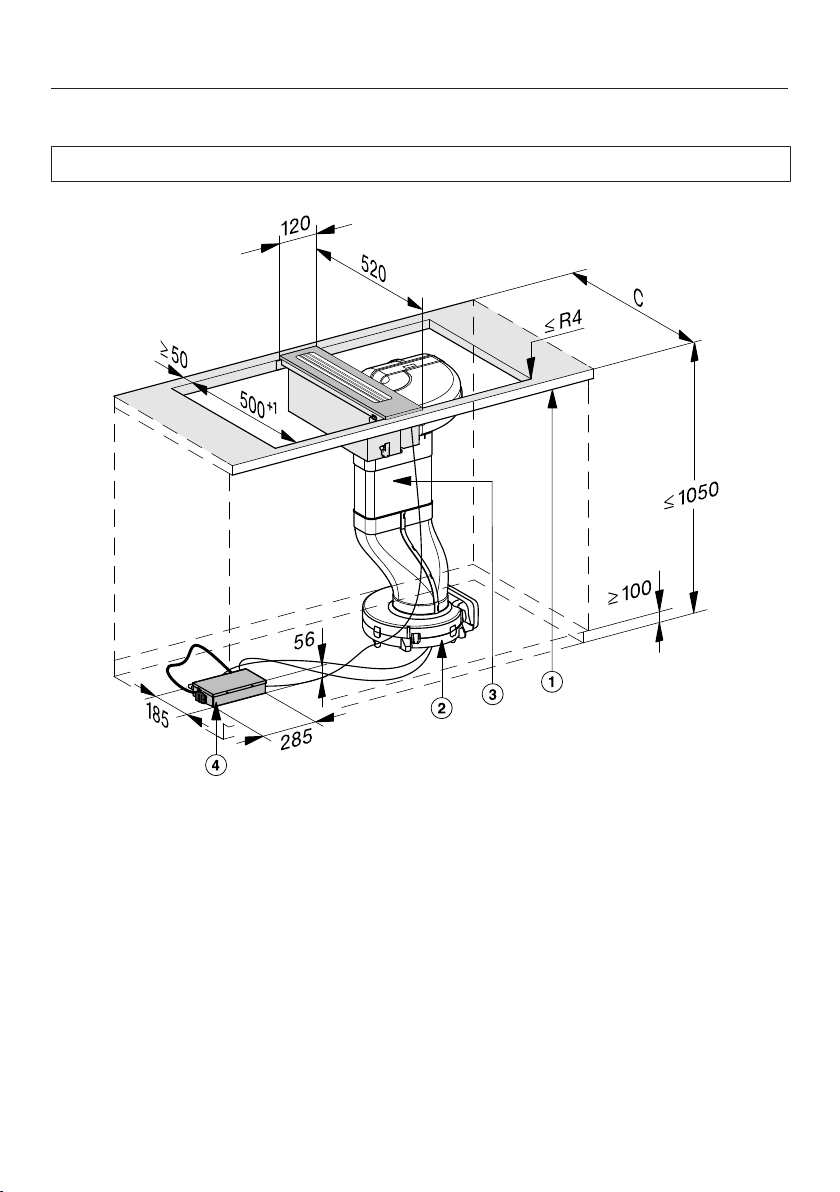
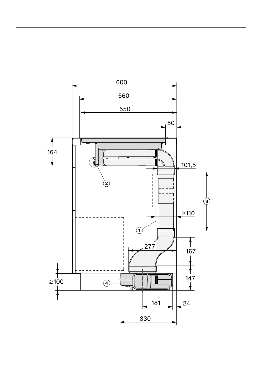
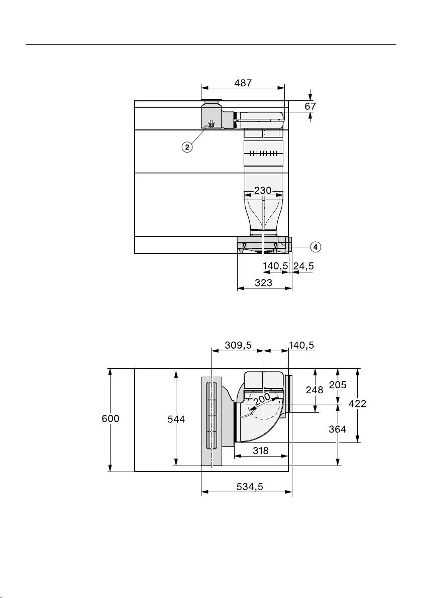
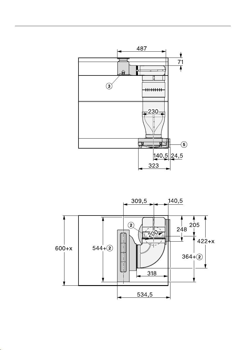
38
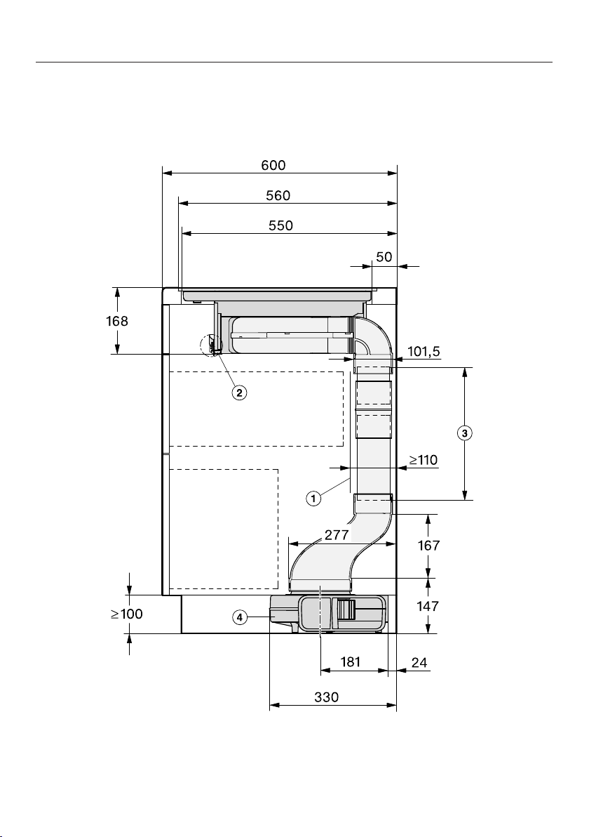
Air duct dimensions – surface-mounted – worktop depth
600mm
Side view

Installation
*INSTALLATION*
39
a
For maintenance work it must be possible to remove the rear cabinet wall.
The cabinet wall and an adjoining room wall or a piece of furniture must be at
least 110mm apart to ensure sufficient room for the ducting.
b
After installation the removable drip tray must be accessible.
2quick-release catches have to be opened at the front and rear to remove the
tray.
c
Duct length must be adapted to the height of the base unit.
Standard delivery 500mm
Installing the length compensation, see chapter “Installation”, section “Installa-
tion – surface-mounted”.
d
Fan
In the plinth on the floor
Installation
*INSTALLATION*
40
Front view
View from above
Installation
*INSTALLATION*
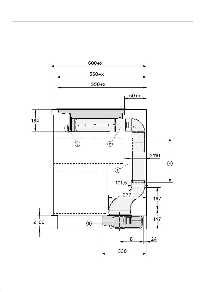
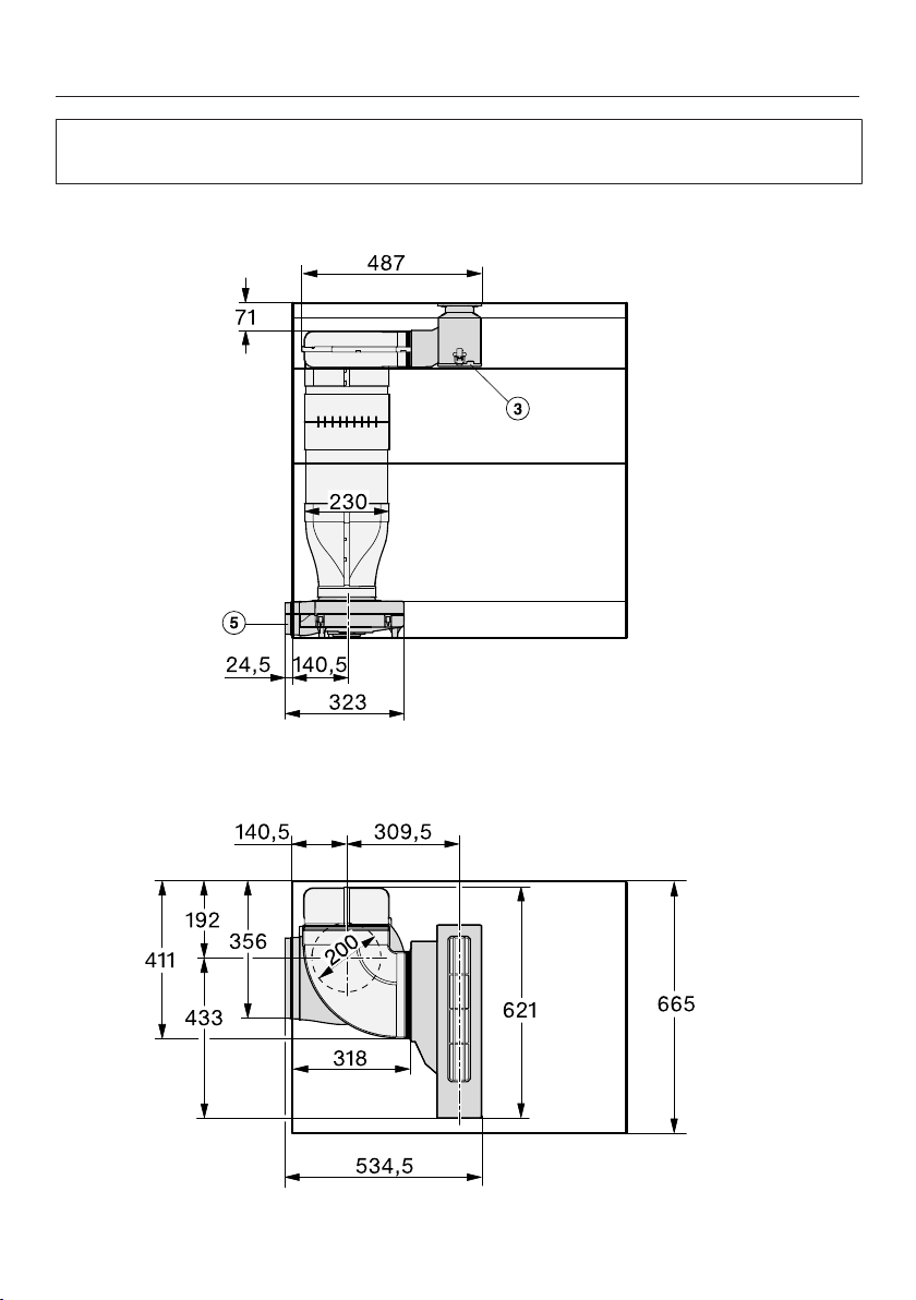
41
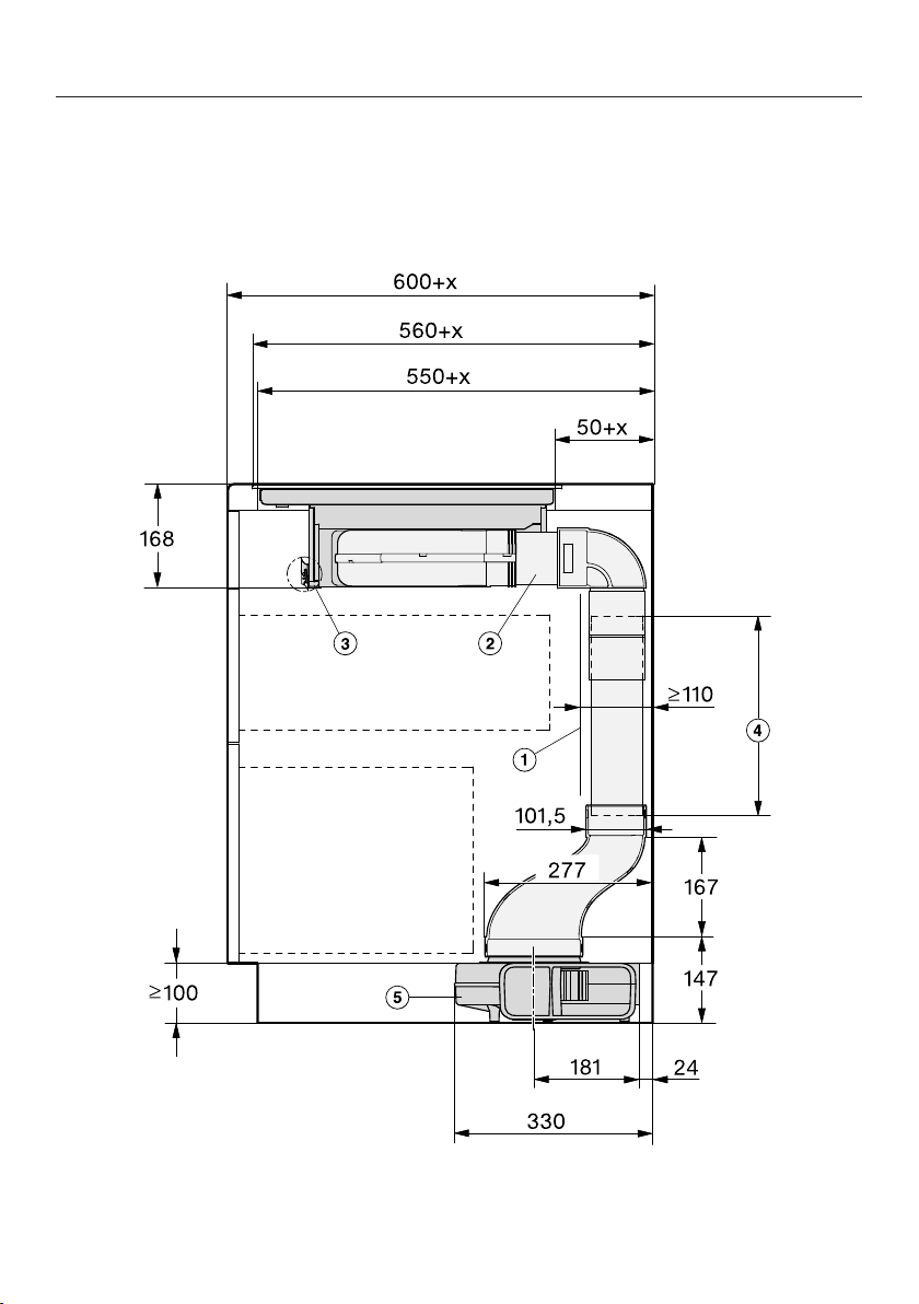
Air duct dimensions – surface-mounted – worktop depth greater
than 600mm
View from the side – right air duct connection

Installation
*INSTALLATION*
42
a
For maintenance work it must be possible to remove the rear cabinet wall.
The cabinet wall and an adjoining room wall or a piece of furniture must be at
least 110mm apart to ensure sufficient room for the ducting.
b
Duct connecter, adapted to the worktop depth
c
After installation the removable drip tray must be accessible.
2quick-release catches have to be opened at the front and rear to remove the
tray.
d
Duct length must be adapted to the height of the base unit.
Standard delivery 500mm
Installing the length compensation, see chapter “Installation”, section “Installa-
tion – surface-mounted”.
e
Fan
In the plinth on the floor
x Dimension of which the worktop is deeper than 600mm.
Installation
*INSTALLATION*
43
View from the front – right air duct connection
View from above – right air duct connection

Installation
*INSTALLATION*
44
If you want to install the air duct to the left of the downdraft extractor, the work-
top must be at least 665mm deep.
View from the front – left air duct connection
View from above – left air duct connection
Installation
*INSTALLATION*
45
Installation – surface-mounted
If the worktop is more than 24mm
deep, it must be cut out underneath
on the building-in side on the right or
left hand side.
a
Worktop
b
Maximum 24mm
c
12mm
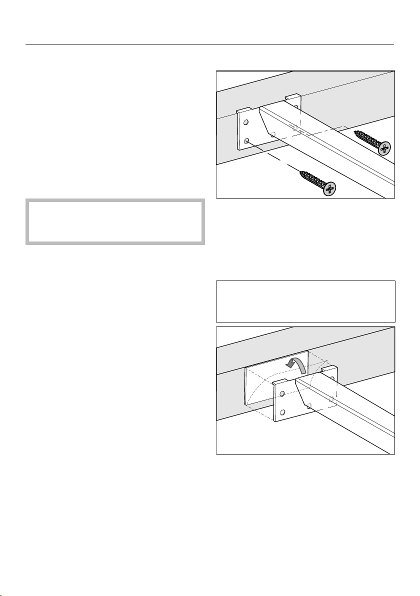
Securing the brackets
1bracket (supplied with the spacer bar)
must be secured centrally to the right or
left-hand side of the cutout.
Wooden worktops
Fit the bracket so that it sits flush
with the top edge of the worktop
cutout.
Secure the bracket with the
3.5x25mm wood screws supplied.
Natural stone worktops
You will need heavy-duty double-
sided tape (not supplied) to secure the
bracket.
Stick the tape along the top edge of
the worktop cutout.
Fit the bracket so that it sits flush
with the top edge of the worktop
cutout.
Press the bracket firmly into position.
Installation
*INSTALLATION*
46
Preparing the worktop
Create the worktop cutout. Remem-
ber to maintain the minimum safety
distances (see “Installation – Safety
distances”).
Seal any cut surfaces on wooden
worktops with a special varnish, sil-
icone sealant or resin to prevent the
wood from swelling as a result of
moisture ingress. The sealant must
be heat-resistant.
Make sure that the sealant does not
come into contact with the top of the
worktop.
Fitting the spacer bars
Use the middle screw holes if one of the
following SmartLine elements is in-
stalled to the right or left of the spacer
bar: CS7611, CS 7641, CS7101(-1),
CS7102(-1)
Wooden worktops
Position the spacer bars flush onto
the upper edge of the cutout.
Secure the spacer bars with the
3.5x25mm wood screws supplied.
Natural stone worktops
You will need heavy-duty double-
sided tape (not supplied) to secure the
spacer bars.
Stick the tape along the top edge of
the worktop cutout.
Position the spacer bars flush onto
the upper edge of the cutout.
Press the spacer bars firmly into
place.
Installation
*INSTALLATION*
47
Installing the countertop extractor
The countertop extractor can be in-
stalled with the connector for the air
duct on either the right or the left-hand
side.
a
Connector for air duct on the right
b
Connector for air duct on the left
Stick the sealing strip supplied under
the edge of the cover. Do not apply
the sealing strip under tension.
Fit the clips onto the spacer bars.
Guide the control cable downwards
between the spacer bars.
Fit the cover onto the spacer bars.
Remove the grease trap from the cas-
ing.
Fasten the casing from the inside with
the screws on the right and left
sides (3 in each case).
Fasten the grease trap.
Installation
*INSTALLATION*
48
Installing the air duct
Mount the air duct.
If the exhaust ducting does not sit se-
curely up against the exhaust duct
connection, stick the sealing strip
supplied to the exhaust duct connec-
tion.
Ensure that the air duct is not under
mechanical tension after installation.
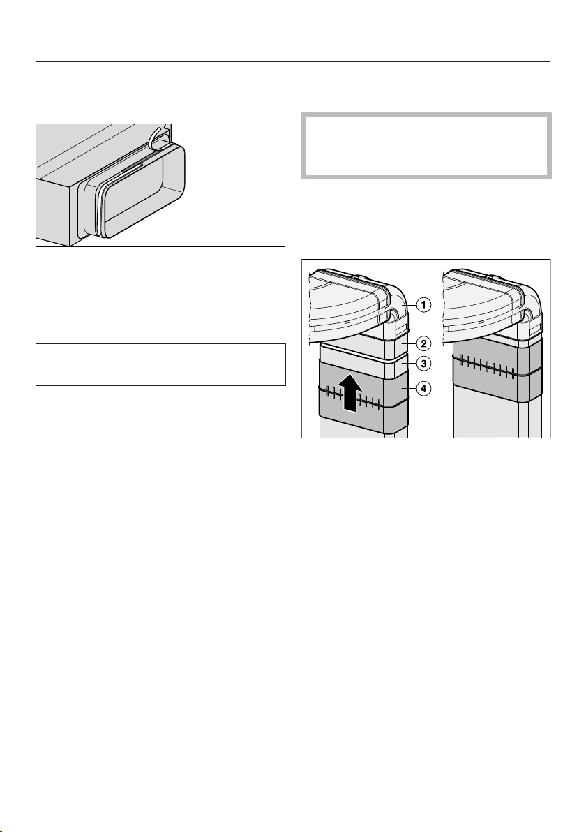
Length compensation
The length compensation facilitates
customer service and repair work. The
installation position of the length com-
pensation depends on the worktop
depth.
Length compensation – worktop
depth 600mm
Length compensation does not fit.
The duct piece must be at least
100mm long.
Divide the flat ducting into 2 pieces to
suit your installation situation. The
upper piece must have a minimum
length of 100mm.
Insert the short bend into the hori-
zontal bend.
Connect the duct piece with the
short bend. Fix the connection
with the sealing strip.
Adapt the remaining duct piece to
the height of the base unit.
Slide the length compensation
over the adapted duct piece. Hold
the adapted duct piece under the
duct piece on the bend. Slide the
length compensation over the duct
piece on the bend. Fix the connec-
tion with the sealing strip.
Installation
*INSTALLATION*
49
Length compensation – worktop
depth greater than 600mm
Divide the flat ducting into 2 pieces. 1
piece must correspond to the differ-
ence between 600mm and the work-
top depth.
Insert the duct piece into the hori-
zontal bend.
Connect the duct piece with the
short bend. Fix the connection
with the sealing strip.
Adapt the remaining duct piece to
the height of the base unit.
Slide the length compensation
over the adapted duct piece. Hold
the adapted duct piece under the
short bend. Slide the length com-
pensation over the short bend
from below. Fix the connection with
the sealing strip.
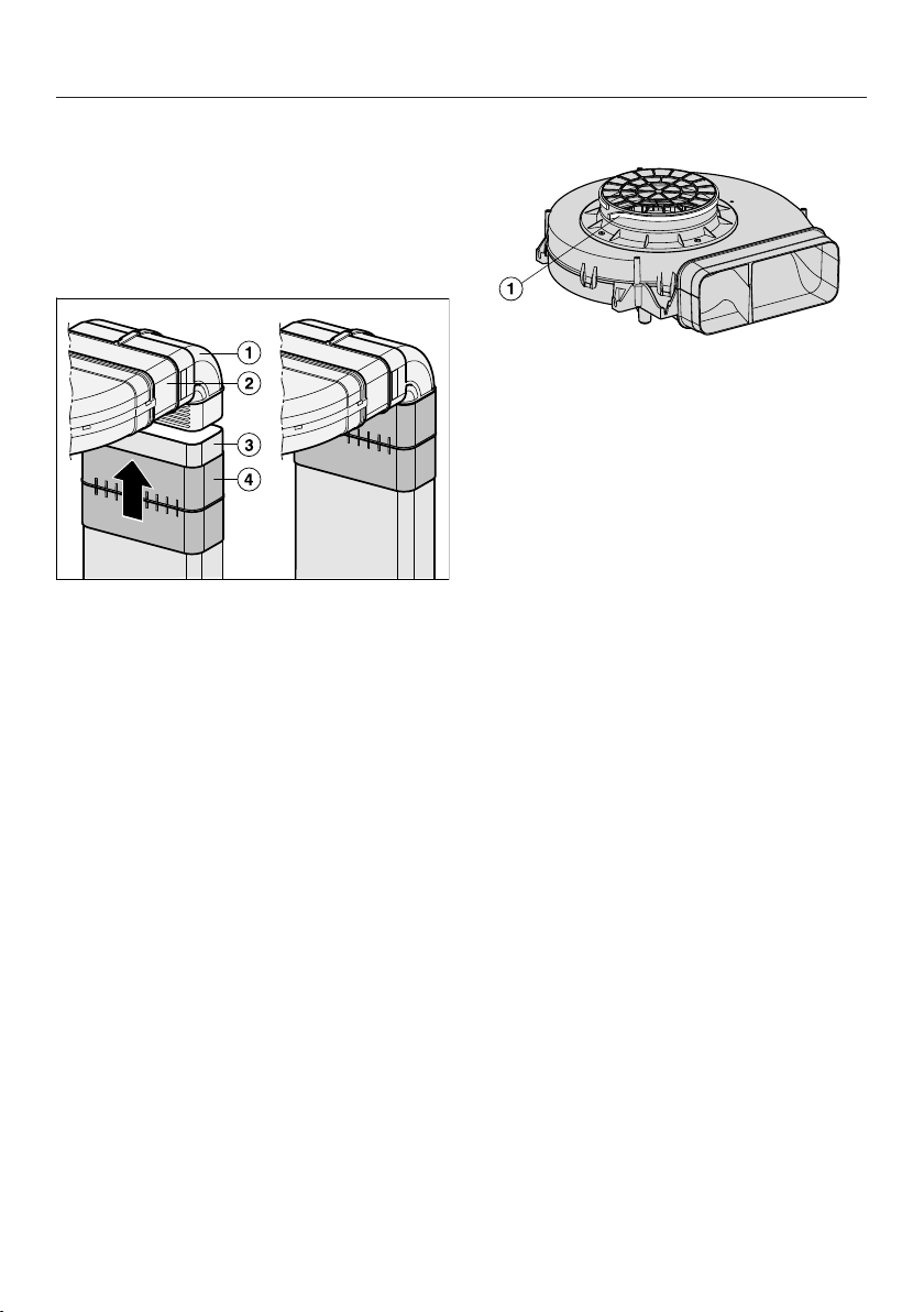
Installing the fan motor
a
Sealing strip
Stick the sealing strip supplied to the
fan connection.
Installation
*INSTALLATION*
50
E-box
a
Mains connection cable
b
Connection to window contact
c
Electrical connection socket for the
fan operating voltage cable
d
Electrical connection socket for the
fan control cable
e
Electrical connection socket for the
control unit cable
Connection to window contact, if re-
quired
The window contact connection
is live!
Danger of electric shock!
Disconnect the countertop extractor
from the mains before connecting
the switching system.
The connection cable of the switch-
ing system must only be connected
by a suitably qualified and compet-
ent electrician.
The connection cable of the switch-
ing system must comply with type
H03VV-F 2x0.75mm
2
and must not
exceed 2.0m in length.
The switching system must be
equipped with a potential-free con-
tact suitable for 230V, 1A. The ex-
tractor is switched off when the
switch is open.
Only use DIPT-approved and tested
radio switching systems (e.g. window
contact switches, pressure switches)
and have them approved by author-
ised specialists (e.g. building regula-
tions inspector).
The switching system must be suit-
able for use with a BLDC motor.
You will need the appropriate ex-
ternal switching system documents
to safely connect and operate the
switch.

Installation
*INSTALLATION*
51
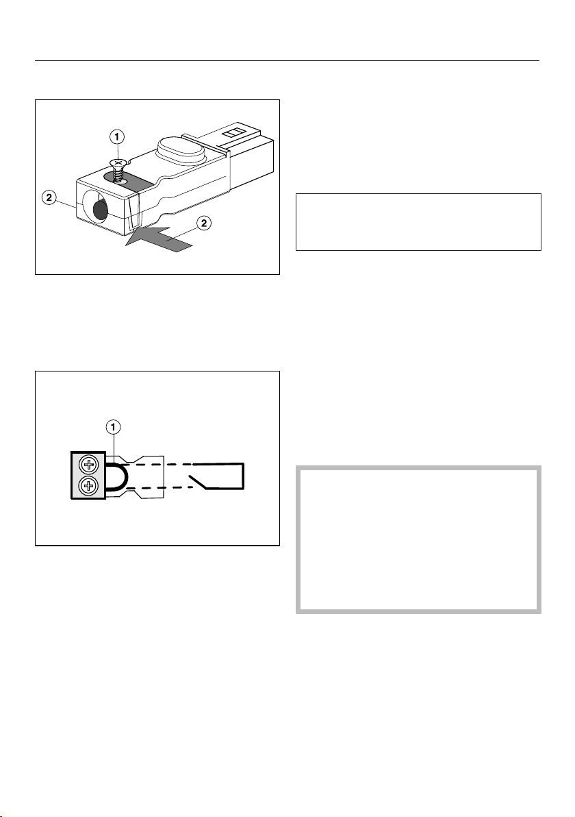
Loosen the lug and pull the plug out.
Loosen the strain relief screw and
unlock the casing on both sides.
Open the casing.
Remove the stopper.
Exchange the bridge for the con-
nection cable of the switching sys-
tem.
Close the casing.
Tighten the strain relief screw.
Reinsert the plug.
Connecting the e-box
Connect the operating voltage and
fan control cables to the e-box and
the fan.
Connect the control unit cable to the
e-box.
The socket positions are designed in
such a way that they cannot be mixed
up.
Connect the downdraft extractor to
the mains.
Check that the downdraft extractor
works.
Sealing the gaps
Seal the gaps between the individual
SmartLine elements, and between the
flush-mounted SmartLine elements
and the worktop, with a silicone seal-
ant that is heat-resistant to at least
160°C.
Unsuitable sealant can damage nat-
ural stone.
For natural stone worktops and nat-
ural stone tiles, only use silicone
sealant that is specially formulated
for natural stone.
Please follow the manufacturer's in-
structions.

Installation
*INSTALLATION*
52
Installation notes –
flush-fit
Flush-fit installation is only possible in
natural stone (granite, marble), solid
wood and tiled worktops. For installa-
tion in worktops made of other materi-
als, please consult the relevant manu-
facturer as to whether their worktops
are suitable for flush-fit installation.
The internal width of the base unit un-
derneath the appliance must be at
least as wide as the inner worktop
cutout (see “Installation – Building-in
dimensions – flush-fit”), so that the
SmartLine element is easily accessible
from underneath after installation and
the bottom half of the casing can be
removed for maintenance. If the ele-
ment is not freely accessible from be-
low after installation, the sealant must
be removed so that the element can
be removed.
Natural stone worktops
The SmartLine element is set directly in
the cutout.
Solid wood worktops, tiled worktops,
glass worktops
The SmartLine element is set on a
wooden frame inside the cutout. The
frame must be provided on site, and is
not supplied with the appliance.
Sealing strip
Dismantling the SmartLine element
for service purposes may damage
the sealing strip underneath the edge
of the SmartLine element.
Always replace the sealing strip be-
fore reinstalling the SmartLine ele-
ment.

Installation
*INSTALLATION*
53
Installing several
SmartLine elements
The gaps between the individual Smart-
Line elements are sealed with a silicone
sealant that is heat-resistant to at least
160°C. With flush-fit installation, the
gap between the SmartLine element(s)
and the worktop must also be sealed
with a silicone sealant that is heat-res-
istant to at least 160°C.
After installation, the SmartLine ele-
ments must be easily accessible from
below, so that the bottom half of the
casing can be removed for mainten-
ance. If the SmartLine elements are not
accessible from below, the sealant must
be removed so that they can be re-
moved.
Worktop depth
The downdraft extractor can be in-
stalled with the connector for the air
duct on either the right or the left-hand
side.
Minimum worktop depth for
- Right connector 600mm
- Left connector 665mm
Installation
*INSTALLATION*
54
Worktop cutout – flush-fit
B
0
50
A
524
500
+
1
+ 1
ß R 4
B
A
0
2
12
0
10
5,5
+
0,5
*
/ 7
+ 0,5
0
2
12
0
10
5,5
+
0,5
*
/ 7
+ 0,5
+ 1
+ 1
+ 1
+ 1
B
A
+ 1
+ 1
Natural stone worktop Wooden worktop
* 7
+
0.5
mm with CS7611FL
Installation
*INSTALLATION*
55
Installation with a countertop extractor
Combination examples Numberxwidth [mm] Dimen-
sionA
[mm]
Dimen-
sionB
[mm]
Cooking ele-
ments
Counter-
top ex-
tractor
1x378 1x120 505 481
2x378 1x120 886 862
1x378
1x620
2x120 1250 1226
3x378 2x120 1389 1365
2x378
1x620
2x120 1631 1607
4x378 2x120 1770 1746
1x620 2x120 869 845
Installation
*INSTALLATION*
56
Installation without a countertop extractor
Combination ex-
amples
Numberxwidth
[mm]
DimensionA
[mm]
DimensionB
[mm]
Cooking elements
1x378 383 359
2x378 764 740
1x378
1x620
1006 982
3x378 1145 1121
2x378
1x620
1387 1363
4x378 1526 1502
2x378
1x800
1567 1543
2x378
1x936
1703 1679
Installation
*INSTALLATION*
57
Spacer bars – flush-fit
If you are installing several appliances, you must fit spacer bars between them.
The clips supplied with the spacer bars are only required for installing a
CSDA700xFL.
Installing 3elements and 2spacer bars
Spacer bars for the downdraft extractor – flush-fit
a
Brackets
Installation
*INSTALLATION*
58
Installation dimensions–Flush-fit
All dimensions are given in mm.
a
Front
b
Fan
In the plinth on the floor
c
Stepped cutout (for detailed illustrations, see “Installation – Worktop cutout –
flush-fit”)
d
12mm wooden frame (not supplied, for detailed illustrations, see “Installation –
Worktop cutout – flush-fit”)
e
Air duct
(supplied as accessory)
f
E-box
Installation
*INSTALLATION*
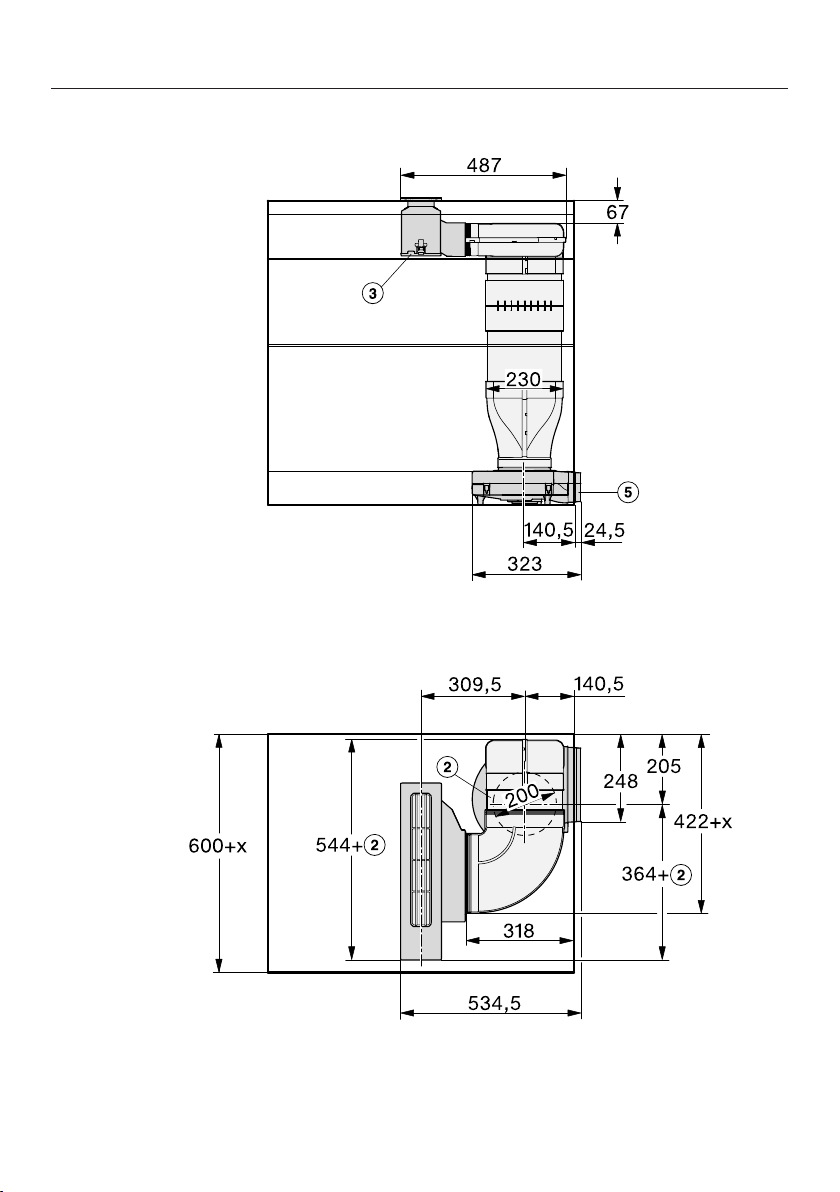
59
Air duct dimensions – flush-fit – worktop depth 600mm
Side view

Installation
*INSTALLATION*
60
a
For maintenance work it must be possible to remove the rear cabinet wall.
The cabinet wall and an adjoining room wall or a piece of furniture must be at
least 110mm apart to ensure sufficient room for the ducting.
b
After installation the removable drip tray must be accessible.
2quick-release catches have to be opened at the front and rear to remove the
tray.
c
Duct length must be adapted to the height of the base unit.
Standard delivery 500mm
Installing the length compensation, see chapter “Installation”, section “Installa-
tion – flush-fit”.
d
Fan
In the plinth on the floor

Installation
*INSTALLATION*
61
Front view
View from above
Installation
*INSTALLATION*
62
Air duct dimensions – flush-fit – worktop depth greater than
600mm
View from the side – right air duct connection

Installation
*INSTALLATION*
63
a
For maintenance work it must be possible to remove the rear cabinet wall.
The cabinet wall and an adjoining room wall or a piece of furniture must be at
least 110mm apart to ensure sufficient room for the ducting.
b
Duct connecter, adapted to the worktop depth
c
After installation the removable drip tray must be accessible.
2quick-release catches have to be opened at the front and rear to remove the
tray.
d
Duct length must be adapted to the height of the base unit.
Standard delivery 500mm
Installing the length compensation, see chapter “Installation”, section “Installa-
tion – flush-fit”.
e
Fan
In the plinth on the floor
x Dimension of which the worktop is deeper than 600mm.
Installation
*INSTALLATION*
64
View from the front – right air duct connection
View from above – right air duct connection
Installation
*INSTALLATION*
65
If you want to install the air duct to the left of the downdraft extractor, the work-
top must be at least 665mm deep.
View from the front – left air duct connection
View from above – left air duct connection
Installation
*INSTALLATION*
66
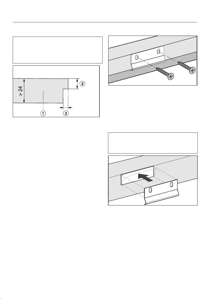
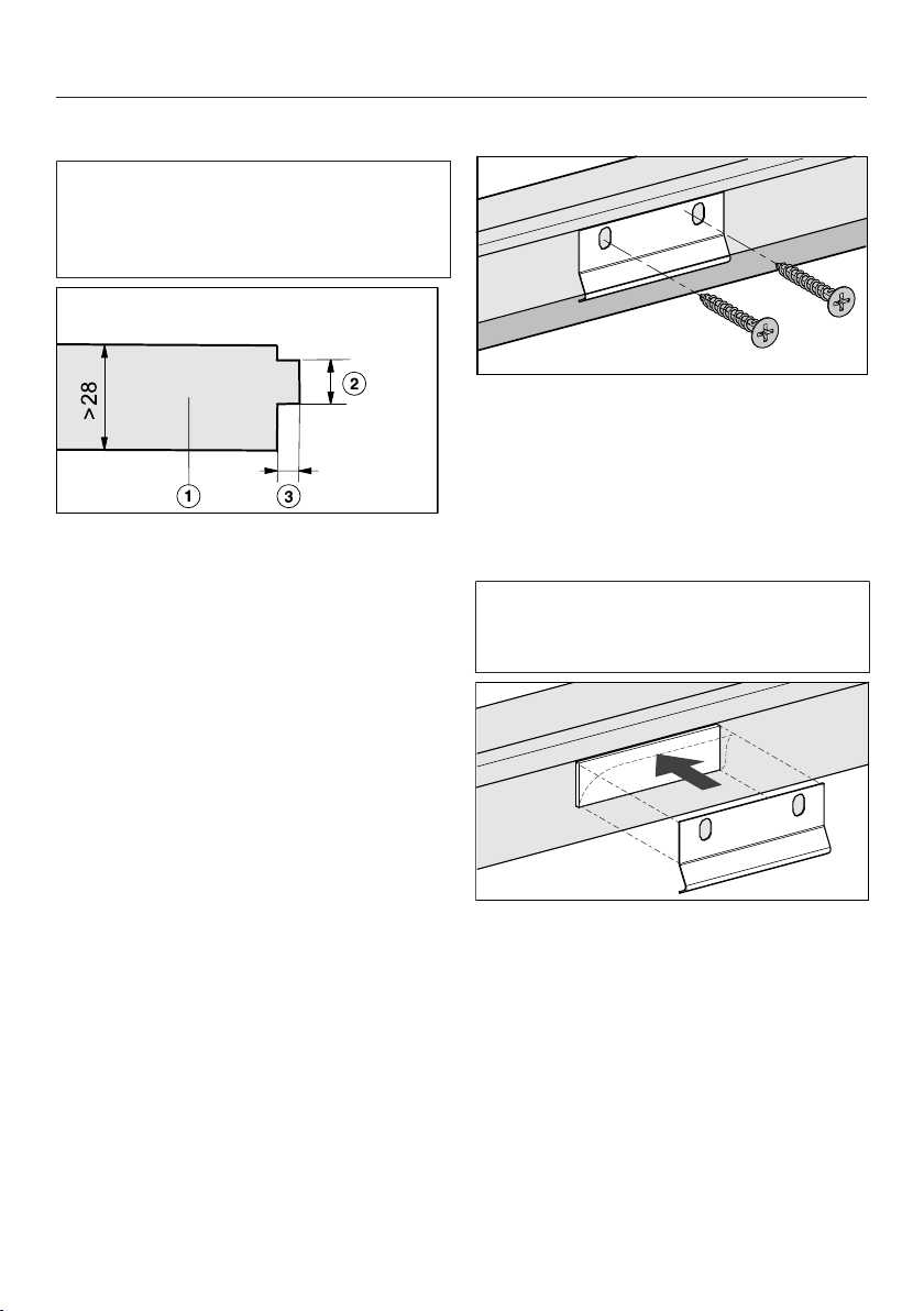
Installation – flush-fit
If the worktop is more than 28mm
deep, it must be cut out underneath
on the building-in side on the right or
left hand side.
a
Worktop
b
Maximum 24mm
c
12mm
Securing the brackets
1bracket (supplied with the spacer bar)
must be secured centrally to the right or
left-hand side of the cutout.
Wooden worktops
Fit the bracket so that it sits flush
with the top edge of the lower step of
the stepped cutout.
Secure the bracket with the
3.5x25mm wood screws supplied.
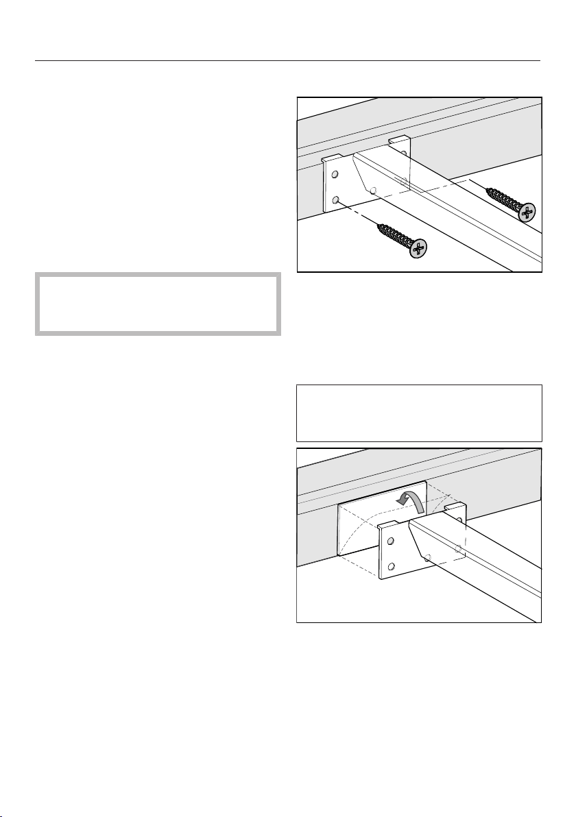
Natural stone worktops
You will need heavy-duty double-
sided tape (not supplied) to secure the
bracket.
Stick the tape onto the upper edge of
the lower step of the stepped cutout.
Fit the bracket so that it sits flush
with the top edge of the lower step of
the stepped cutout.
Press the bracket firmly into position.
Installation
*INSTALLATION*
67
Preparing the worktop
Create the worktop cutout. Remem-
ber to maintain the minimum safety
distances (see “Installation – Safety
distances”).
Seal any cut surfaces on wooden
worktops with a special varnish, sil-
icone sealant or resin to prevent the
wood from swelling as a result of
moisture ingress. The sealant must
be heat-resistant.
Make sure that the sealant does not
come into contact with the top of the
worktop.
For wooden worktops, secure the
wooden frame 5.5mm below the up-
per edge of the worktop.
For CS7611FL, the wooden frame
must be secured 7mm under the up-
per edge of the worktop.
Fitting the spacer bars
Use the middle screw holes if one of the
following SmartLine elements is in-
stalled to the right or left of the spacer
bar: CS7611, CS 7641, CS7101(-1),
CS7102(-1)
Wooden worktops
Position the spacer bars flush onto
the lower step of the stepped cutout.
Secure the spacer bars with the
3.5x25mm wood screws supplied.
Natural stone worktops
You will need heavy-duty double-
sided tape (not supplied) to secure the
spacer bars.
Stick the tape onto the lower step of
the stepped cutout.
Position the spacer bars flush onto
the lower step of the stepped cutout.
Press the spacer bars firmly into
place.

Installation
*INSTALLATION*
68
Installing the countertop extractor
The countertop extractor can be in-
stalled with the connector for the air
duct on either the right or the left-hand
side.
a
Connector for air duct on the right
b
Connector for air duct on the left
Stick the sealing strip supplied under
the edge of the cover. Do not apply
the sealing strip under tension.
Fit the clips onto the spacer bars.
Guide the control cable downwards
between the spacer bars.
Fit the cover onto the spacer bars.
Remove the grease trap from the cas-
ing.
Fasten the casing from the inside with
the screws on the right and left
sides (3 in each case).
Fasten the grease trap.

Installation
*INSTALLATION*
69
Installing the air duct
Mount the air duct.
If the exhaust ducting does not sit se-
curely up against the exhaust duct
connection, stick the sealing strip
supplied to the exhaust duct connec-
tion.
Ensure that the air duct is not under
mechanical tension after installation.
Length compensation
The length compensation facilitates
customer service and repair work. The
installation position of the length com-
pensation depends on the worktop
depth.
Length compensation – worktop
depth 600mm
Length compensation does not fit.
The duct piece must be at least
100mm long.
Divide the flat ducting into 2 pieces to
suit your installation situation. The
upper piece must have a minimum
length of 100mm.
Insert the short bend into the hori-
zontal bend.
Connect the duct piece with the
short bend. Fix the connection
with the sealing strip.
Adapt the remaining duct piece to
the height of the base unit.
Slide the length compensation
over the adapted duct piece. Hold
the adapted duct piece under the
duct piece on the bend. Slide the
length compensation over the duct
piece on the bend. Fix the connec-
tion with the sealing strip.

Installation
*INSTALLATION*
70
Length compensation – worktop
depth greater than 600mm
Divide the flat ducting into 2 pieces. 1
piece must correspond to the differ-
ence between 600mm and the work-
top depth.
Insert the duct piece into the hori-
zontal bend.
Connect the duct piece with the
short bend. Fix the connection
with the sealing strip.
Adapt the remaining duct piece to
the height of the base unit.
Slide the length compensation
over the adapted duct piece. Hold
the adapted duct piece under the
short bend. Slide the length com-
pensation over the short bend
from below. Fix the connection with
the sealing strip.
Installing the fan motor
a
Sealing strip
Stick the sealing strip supplied to the
fan connection.

Installation
*INSTALLATION*
71
E-box
a
Mains connection cable
b
Connection to window contact
c
Electrical connection socket for the
fan operating voltage cable
d
Electrical connection socket for the
fan control cable
e
Electrical connection socket for the
control unit cable
Connection to window contact, if re-
quired
The window contact connection
is live!
Danger of electric shock!
Disconnect the countertop extractor
from the mains before connecting
the switching system.
The connection cable of the switch-
ing system must only be connected
by a suitably qualified and compet-
ent electrician.
The connection cable of the switch-
ing system must comply with type
H03VV-F 2x0.75mm
2
and must not
exceed 2.0m in length.
The switching system must be
equipped with a potential-free con-
tact suitable for 230V, 1A. The ex-
tractor is switched off when the
switch is open.
Only use DIPT-approved and tested
radio switching systems (e.g. window
contact switches, pressure switches)
and have them approved by author-
ised specialists (e.g. building regula-
tions inspector).
The switching system must be suit-
able for use with a BLDC motor.
You will need the appropriate ex-
ternal switching system documents
to safely connect and operate the
switch.
Installation
*INSTALLATION*
72
Loosen the lug and pull the plug out.
Loosen the strain relief screw and
unlock the casing on both sides.
Open the casing.
Remove the stopper.
Exchange the bridge for the con-
nection cable of the switching sys-
tem.
Close the casing.
Tighten the strain relief screw.
Reinsert the plug.
Connecting the e-box
Connect the operating voltage and
fan control cables to the e-box and
the fan.
Connect the control unit cable to the
e-box.
The socket positions are designed in
such a way that they cannot be mixed
up.
Connect the downdraft extractor to
the mains.
Check that the downdraft extractor
works.
Sealing the gaps
Seal the gaps between the individual
SmartLine elements, and between the
flush-mounted SmartLine elements
and the worktop, with a silicone seal-
ant that is heat-resistant to at least
160°C.
Unsuitable sealant can damage nat-
ural stone.
For natural stone worktops and nat-
ural stone tiles, only use silicone
sealant that is specially formulated
for natural stone.
Please follow the manufacturer's in-
structions.
Installation
*INSTALLATION*
73
Ducting
If the downdraft extractor is used
at the same time as a heating appli-
ance that relies on oxygen from the
same room, there is a risk of toxic
fumes.
It is essential that the “Warning and
Safety” instructions are observed.
The downdraft extractor should be
installed according to local and na-
tional building regulations. Seek ap-
proval from the building inspector
where necessary.
The downdraft extractor has an exhaust
connection of 222x89mm.
Only use smooth pipes or flexible ex-
haust hoses made from non-flam-
mable materials for exhaust ducting.
To achieve the most efficient air
throughput with the lowest noise
levels, please note the following:
- The cross-section of the ducting
must not be smaller than the cross-
section of the exhaust duct connec-
tion (see “Appliance dimensions”).
- The ducting should be as short and
straight as possible.
- Only use wide radius bends.
- The exhaust ducting must not be
kinked or compressed.
- Ensure that all connections are
strong and airtight.
Remember that any constriction of
the air flow will reduce air throughput
and increase operating noise.
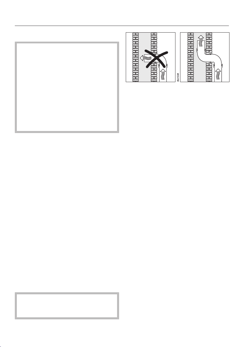
If the exhaust air is to be ducted into
a flue, the ducting must be directed in
the flow direction of the flue.
If ducting is to be laid horizontally it
must be laid with a downwards slop-
ing gradient. This is to ensure that
condensate cannot drain back into
the fan.
If the ducting is to run through rooms,
ceiling space, etc. there may be great
variations in temperature between the
different areas. The problem of con-
densation will need to be addressed.
The ducting will need to be suitably
insulated.

Installation
*INSTALLATION*
74
Electrical connection
The SmartLine element is supplied with
a mains cable with moulded plug ready
for connection to a suitable earthed
socket.
The socket must be easily accessible
after the SmartLine element has been
installed. If the socket is not easily ac-
cessible, ensure that a suitable means
of disconnection is provided on the in-
stallation side for each pole.
Risk of fire from overheating.
Connecting the SmartLine element to
multi-socket adapters or extension
cables can overload the cables.
For safety reasons, do not use an ex-
tension cable or multi-socket ad-
apter.
The electrical installation must comply
with BS7671 requirements.
For safety reasons, we recommend us-
ing a type residual current device
(RCD) in the relevant electrical installa-
tion for connecting the SmartLine ele-
ment.
If the mains connection cable is dam-
aged, it must only be replaced with a
specific mains connection cable of the
same type (available from the Miele
Customer Service Department). For
safety reasons, such replacement may
only be carried out by a qualified spe-
cialist or the Miele Customer Service
Department.
These operating instructions and the
data plate indicate the nominal power
consumption and the appropriate fuse
rating. Compare this information with
the data of the on-site electrical con-
nection.
If in any doubt, consult a qualified elec-
trician.
Temporary or permanent operation on
an autonomous power supply system or
a power supply system that is not syn-
chronised with the mains power supply
(e.g. island networks, back-up systems)
is possible. A prerequisite for operation
is that the power supply system com-
plies with the specifications of
EN50160 or an equivalent standard.
The function and operation of the pro-
tective measures provided in the do-
mestic electrical installation and in this
Miele product must also be maintained
in isolated operation or in operation that
is not synchronised with the mains
power supply, or these measures must
be replaced by equivalent measures in
the installation. As described, for ex-
ample, in the current version of BS OH-
SAS 18001–2 ISO 45001.
Product data sheets
75
The following data sheets apply to the models described in this operating instruc-
tion manual.
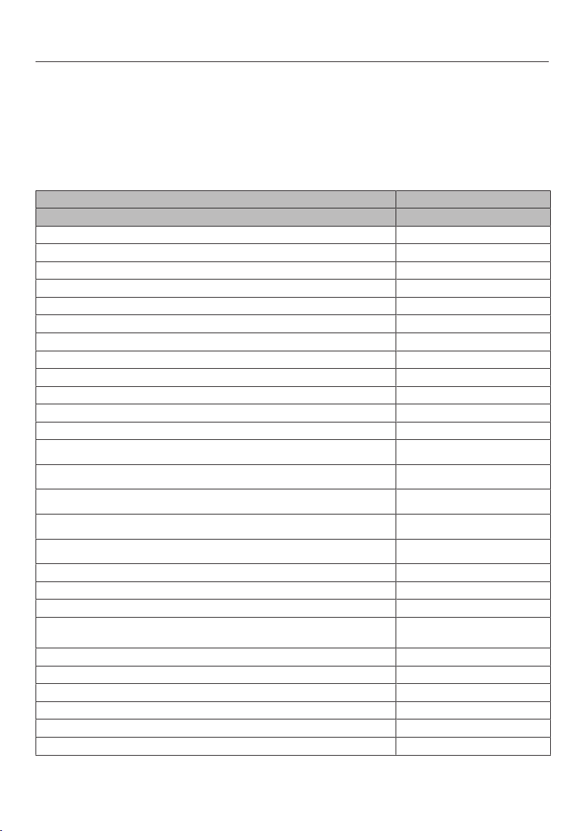
Data sheet for household cooker hoods
In acc. with delegated regulation (EU) No. 65/2014 and regulation (EU) No.
66/2014
MIELE
Model name/identifier CSDA 7001 FL
Annual Energy Consumption (AEC
hood
) 25,3 kWh/year
Energy efficiency class A++
Energy efficiency index (EEI
hood
) 35,8
Fluid Dynamic Efficiency (FDE
hood
) 36,4
Fluid Dynamic Efficiency class
A (most efficient) to G (least efficient) A
Lighting Efficiency (LE
hood
) lx/W
Lighting Efficiency class
A (most efficient) to G (least efficient) -
Grease Filtering Efficiency 93,3%
Grease Filtering Efficiency class
A (most efficient) to G (least efficient) B
Airflow at best efficiency point
294,5 m
3
/h
Air flow (min. speed)
145 m
3
/h
Air flow (max. speed)
460 m
3
/h
Air flow (intensive or boost setting)
560 m
3
/h
Max. air flow (Q
max
)
560 m
3
/h
Air pressure at best efficiency point 448 Pa
Airborne acoustical A-weighted sound power emissions (min. speed) 39 dB
Airborne acoustical A-weighted sound power emissions (max. speed) 65 dB
Airborne acoustical A-weighted sound power emissions (intensive or
boost setting)
69 dB
Electrical power input at best efficiency point 100,6 W
Power consumption in off mode (P
o
) W
Power consumption in standby mode (P
s
) 0,30 W
Nominal power of lighting system 0,0 W
Average illumination of the lighting system on the cooking surface 0 Ix
Time increase factor 0,7


United Kingdom
Miele Co. Ltd., Fairacres, Marcham Road, Abingdon, Oxon, OX14 1TW
Tel: 0330 160 6600, Internet: www.miele.co.uk/service, E-mail: [email protected]
Australia
Miele Australia Pty. Ltd.
ACN 005 635 398
ABN 96 005 635 398
1 Gilbert Park Drive
Knoxfield, VIC 3180
Tel: 1300 464 353
Internet: www.miele.com.au
Miele Electrical Appliances Co., Ltd.
1-3 Floor, No. 82 Shi Men Yi Road
Jing' an District
200040 Shanghai, PRC
Tel: +86 21 6157 3500
Fax: +86 21 6157 3511
E-mail: [email protected],
Internet: www.miele.cn
China Mainland
Miele (Hong Kong) Ltd.
41/F - 4101, Manhattan Place
23 Wang Tai Road
Kowloon Bay, Hong Kong
Tel: (852) 2610 1025
Fax: (852) 3579 1404
Email:
Website: www.miele.hk
Hong Kong, China
Miele India Pvt. Ltd.
1st Floor, Copia Corporate Suites,
Commercial Plot 9,
Mathura Road, Jasola,
New Delhi - 110025
E-mail: customercare@miele.in
Website: www.miele.in
India
Miele Ireland Ltd.
2024 Bianconi Avenue
Citywest Business Campus
Dublin 24
Tel: (01) 461 07 10
Fax: (01) 461 07 97
E-Mail: [email protected]
Internet: www.miele.ie
Ireland
Malaysia
Miele Sdn Bhd
Suite 12-2, Level 12
Menara Sapura Kencana
Petroleum
Solaris Dutamas No. 1
Jalan Dutamas 1
50480 Kuala Lumpur, Malaysia
Phone: +603-6209-0288
Fax: +603-6205-3768
Miele New Zealand Limited
IRD 98 463 631
8 College Hill
Freemans Bay, Auckland 1011
New Zealand
Tel: 0800 464 353
Internet: www.miele.co.nz
New Zealand
Miele Pte. Ltd.
29 Media Circle
#11-04 ALICE@Mediapolis
Singapore 138565
sTel: +65 6735 1191
Fax: +65 6735 1161
E-Mail: [email protected]
Internet: www.miele.sg
Singapore
Miele (Pty) Ltd.
63 Peter Place
Bryanston 2194
P.O. Box 69434
Bryanston 2021
Tel: (011) 875 9000
Fax: (011) 875 9035
E-mail: [email protected]
Internet: www.miele.co.za
South Africa
Miele Appliances Ltd.
Showroom 1
Eiffel 1 Building
P.O. Box 114782 - Dubai
Tel. +971 4 3044 999
Fax. +971 4 3418 852
800-MIELE (64353)
E-Mail: [email protected]
Website: www.miele.ae
United Arab Emirates
Manufacturer:
Miele & Cie. KG, Carl-Miele-Straße 29, 33332 Gütersloh, Germany
Thailand
Miele Appliances Ltd.
BHIRAJ TOWER at EmQuartier
43rd Floor Unit 4301-4303
689 Sukhumvit Road
North Klongton Sub-District
Vadhana District
Bangkok 10110, Thailand
Sheikh Zayed Road, Umm Al Sheif

M.-Nr. 11 480 260 / 03en-GB
CSDA7001 FL