Loading ...
Loading ...
Loading ...
WARNING – SERVICING TO BE CARRIED OUT ONLY BY AN AUTHORISED PERSON
Disconnect from electricity and gas before servicing. Check appliance is safe when you have nished.
41
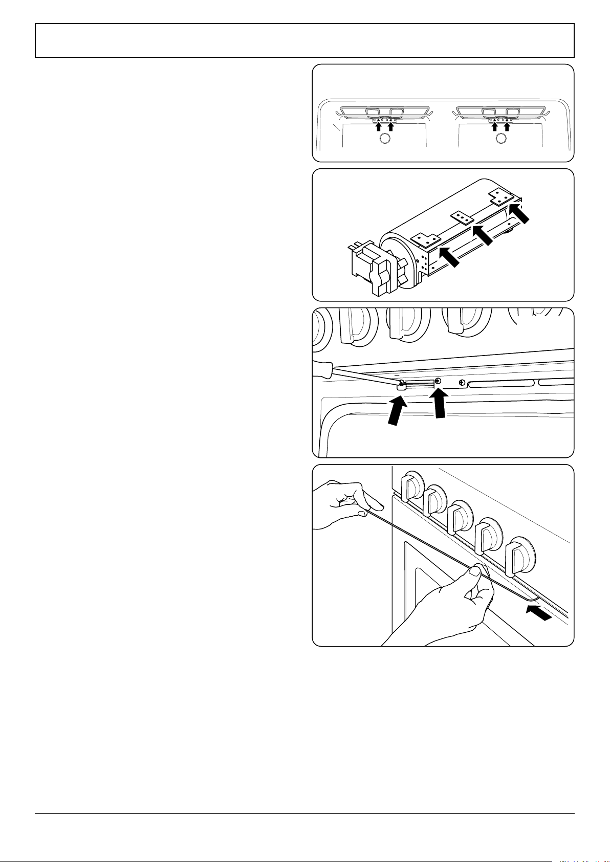
7. 4.7 To Replace the Top and Bottom Elements
DISCONNECT FROM THE ELECTRICITY SUPPLY.
Bottom Element
Pull the cooker forward to allow access to the cover boxes at
the rear. Remove the xings that secure the cover and lift it
clear.
Remove the 2 screws ‘A’ and allow the plate to drop down.
Remove the 2 screws ‘B’, and then lower the upper plate and
remove it through the slot in the cooker back (Fig. 11.11).
Undo the terminal connections, noting their positions.
Remove the element xings and withdraw the element.
Replace the element and reassemble the parts in reverse
order.
Top Element
Remove the top element bracket xings and withdraw the
elements carefully, lifting to clear the clips on the support bar
(Fig. 11.12).
Replace the element and reassemble the parts in reverse
order.
Check that the oven operates satisfactorily.
8. To Replace the Cooling Fan
Remove the hotplate (see 1. To Remove the Hotplate).
Remove the access plate.
Remove the screws that hold the cooling fan to the duct (Fig.
11.13), and then lift out the fan.
Reassemble in reverse order.
9. To Replace the Oven Latch Motor
Remove the packing and accessories from the appliance
except the base pack that can be left in place.
Remove the hotplate (see see 1. To Remove the Hotplate).
Disconnect the thermal cut-out. Disconnect the motor leads
from the terminal block.
Undo the 3 cover plate screws and remove the plate.
Open the oven door and undo the 2 latch assembly retaining
screws (Fig. 11.14).
Remove the black, orange and purple wires connected to the
latch motor. Remove the latch motor assembly.
NOTE: The access to the assembly is very tight; it is suggested
that the assembly is slid into the cooker so that the latch can
be turned sideways and then lifted out front rst.
Replace the motor and ret in reverse order.
Fig. 11.12
Fig. 11.13
Fig. 11.14
Fig. 11.15
Loading ...
Loading ...
Loading ...