Loading ...
Loading ...
Loading ...

WARNING – SERVICING TO BE CARRIED OUT ONLY BY AN AUTHORISED PERSON
Disconnect from electricity and gas before servicing. Check appliance is safe when you have nished.
38
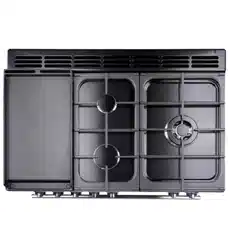
2. Hotplate
1. To Remove the Hotplate
DISCONNECT FROM THE ELECTRICITY SUPPLY.
Remove the pan supports and burner heads.
Remove the 10 screws (2 per burner) holding the hotplate
burners to the hotplate. Remove the 8 screws holding the
hotplate tray to the cooker (Fig. 11.4).
Taking care not to damage the burner heads, lift the hotplate
clear of the cooker.
Reassemble in reverse order, making sure that the leads are
reconnected correctly. Check the operation of each burner.
2. To Replace the Hotplate Control Taps
DISCONNECT FROM THE ELECTRICITY SUPPLY.
Remove the control panel (see 1. To Remove the Control
Panel) and hotplate (see 1. To Remove the Hotplate).
Unplug the FSD lead from the rear of the tap. Undo
compression tting at the rear of the tap. Remove the xings
that secure the tap to the gas rail.
Disconnect the ignition switch wiring. Remove the tap, then
remove and discard the gasket seal.
Fit the new gasket seal to the replacement tap.
Reassemble in reverse order. Check the cooker is gas sound.
Check the hotplate ignition.
3. To Change a Hotplate Burner Injector
DISCONNECT FROM THE ELECTRICITY SUPPLY.
Remove the pan supports, burner cap and head. Remove the
old jet. Fit the new injector.
Reassemble in reverse order. Check the cooker is gas sound.
4. To Replace a Hotplate Burner Electrode
DISCONNECT FROM THE ELECTRICITY SUPPLY.
Lift o the pan supports and remove the burner cap. Remove
the screw holding the electrode. Pull the electrode vertically
up suciently to grip the lead between thumb and forenger.
Pull o the electrode but keep hold of the lead.
Fit the new electrode to the lead and x the electrode to the
burner. Replace the burner cap. Check the burner ignition.
5. To Replace a Hotplate Burner
DISCONNECT FROM THE ELECTRICITY SUPPLY.
Remove the hotplate (see 1. To Remove the Hotplate).
All of the burners (except the wok burner) are mounted
on support struts. Disconnect the burner feed pipes at the
burner. Remove the screws at the front and rear holding the
support struts. Lift the strut and burners clear. The burners are
xed to the support struts with 2screws.
Remove the appropriate burner and t the new one.
Reassemble in reverse order. Check that the burner operation
is satisfactory.
Wok Burner
Disconnect the burner feed pipes at the burner. Fit the new
one and reassemble in reverse order. Check that the burner
operation is satisfactory.
1. To Replace a Hotplate Burner Thermocouple
DISCONNECT FROM THE ELECTRICITY SUPPLY.
Remove the hotplate (see 1. To Remove the Hotplate).
Identify the thermocouple to be removed. Pull o the
connection at the tap end and lift the thermocouple away at
the burner end.
Fit the new thermocouple in the reverse order.
Replace the hotplate. Check the thermocouple for correct
operation at full rate and turndown.
3. Controls
1. To Replace the Ignition or light Switch
DISCONNECT FROM THE ELECTRICITY SUPPLY.
Remove the control panel (see 1. To Remove the Control ).
NOTE: The old switch may be destroyed during removal.
Remove the switch button and old switch from its bezel
by gripping the switch body behind the control panel and
twisting sharply. Remove the switch bezel by folding back the
locking wings and pushing forwards.
Fit the new bezel to the control panel by rst lining up the
raised key on its body with the cut-out in the control panel
and pushing it in from the front. Assemble the new switch to
the bezel by lining up the key sections and pushing home.
Fit the new button by pushing in from the front.
Replace control panel in reverse order and test for correct
operation.
2. To Replace the Clock
DISCONNECT FROM THE ELECTRICITY SUPPLY.
Remove the control panel (see 1. To Remove the Control
Panel ). Pull o the timer control buttons.
Undo the timer/mounting bracket assembly xing screws and
remove the assembly from the control panel.
Remove the timer from its mounting bracket by depressing
the plastic lugs on the timer case, while at the same time
pulling the unit forward.
Reassemble in reverse order. When replacing the leads, refer
to the wiring diagram.
Check the operation of the timer.
Loading ...
Loading ...
Loading ...