


This document is a publication by Julius Tielbürger GmbH & Co. KG, Postdamm 12, D-32351 Stemwede-Oppenwehe, Germa-
ny (www.tielbuerger.de).
The document is up to date with the latest technology at the time of printing. Subject to technical and equipment changes. The
drawings and illustrations shown may differ from the original.
$OOULJKWVUHVHUYHGLQFOXGLQJWKRVHRIWUDQVODWLRQ$Q\W\SHRIUHSURGXFWLRQVXFKDVSKRWRFRS\PLFUR¿OPRUVWRULQJLQHOHF-
tronic data processing systems, requires written authorisation from the publisher. Any reproduction, whether in whole or in
part, is prohibited.
All trademarks, registered trademarks, trade names and brand names are the property of their rightful owners and are acknowl-
edged by us.
© Copyright 2017 by Julius Tielbürger GmbH & Co. KG

3
3
Content
1 Operating and installation instructions ....................................................................................................................... 4
1.1 General ..................................................................................................................................................................... 4
1.2 Warnings and symbols .............................................................................................................................................. 5
2 Basic safety instructions ................................................................................................................................................ 6
2.1 Intended use .............................................................................................................................................................. 6
2.2 Organisational measures ........................................................................................................................................... 6
3HUVRQQHOVHOHFWLRQDQGTXDOL¿FDWLRQVEDVLFREOLJDWLRQV ......................................................................................... 7
2.4 Position of safety stickers and labels ........................................................................................................................ 7
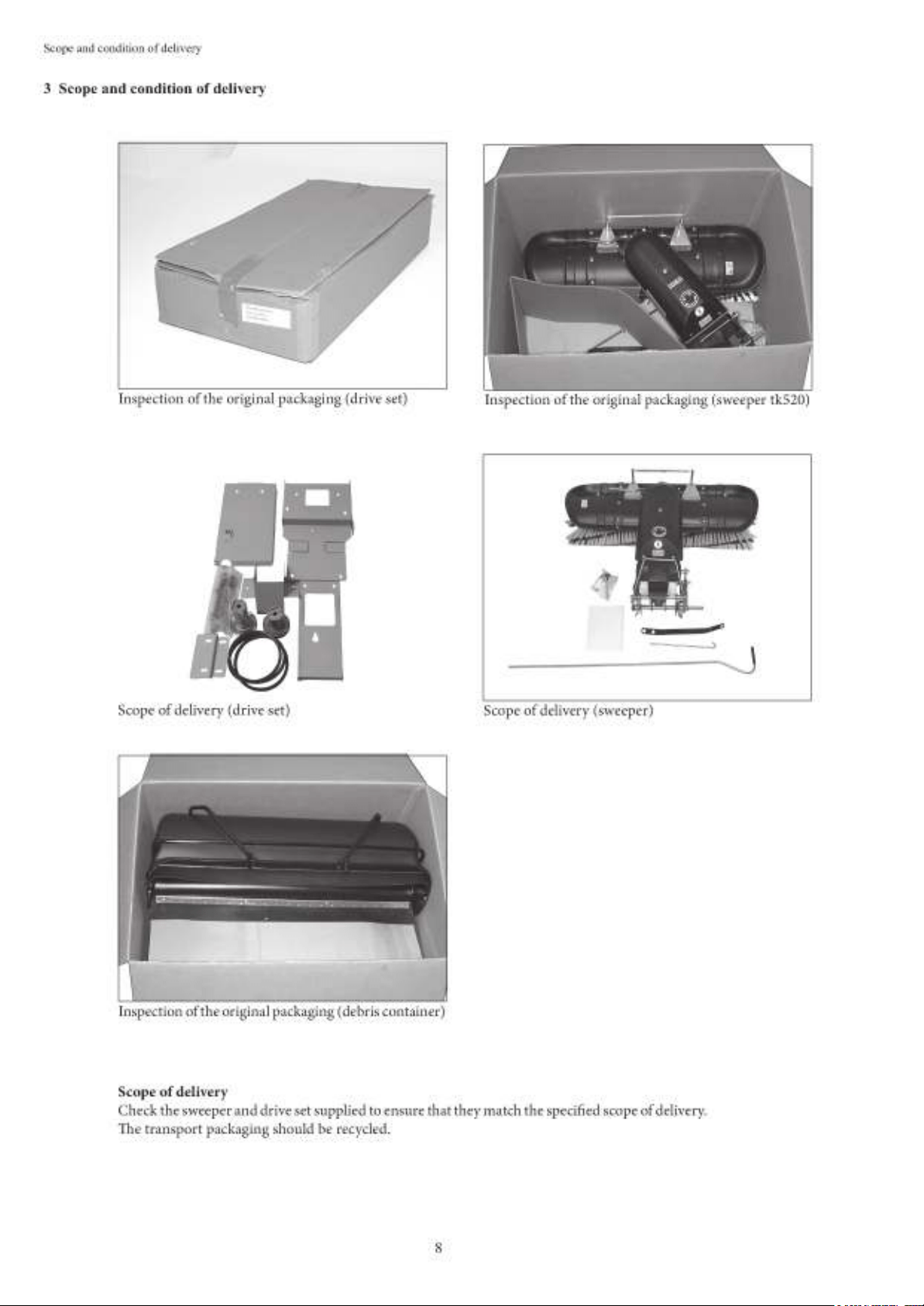
3 Scope and condition of delivery .................................................................................................................................... 8
4 Illustration of the machine and danger zone, component description, position of safety stickers and labels ....... 9
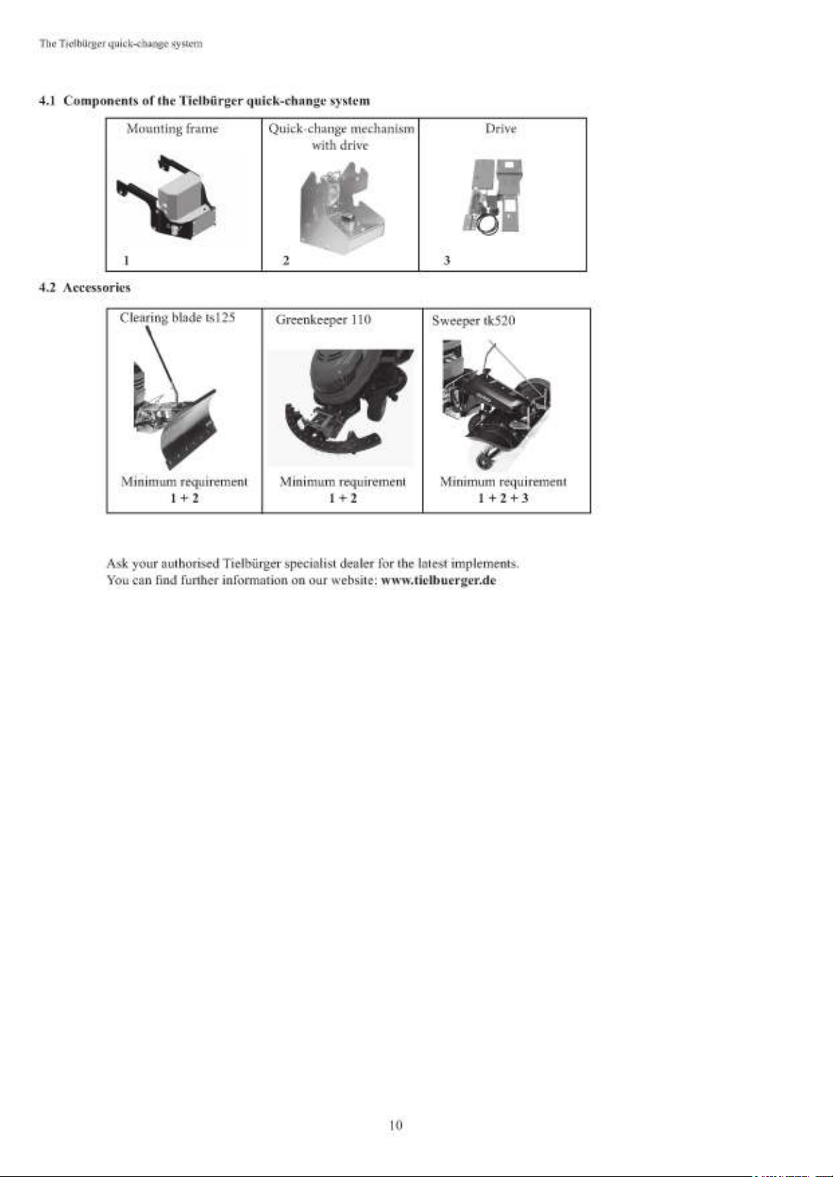
4.1 Components of the Tielbürger quick-change system ............................................................................................. 10
4.2 Accessories ............................................................................................................................................................. 10
5 Installation .....................................................................................................................................................................11
5.1 Preparatory measures prior to installation .............................................................................................................. 11
5.2 Installation .............................................................................................................................................................. 12
5.3 Drive set installation ............................................................................................................................................... 13
5.4 Sweeper attachment installation ............................................................................................................................. 25
6 Start-up ......................................................................................................................................................................... 31
6.1 Basic safety instructions for normal operation ....................................................................................................... 31
6.2 Coupling and uncoupling the sweeper ................................................................................................................... 32
6.3 Brush pressure ........................................................................................................................................................ 34
6.4 Setting the ejection direction .................................................................................................................................. 35
6.5 Debris container .................................................................................................................................................... 36
6.6 Emptying the debris container ............................................................................................................................... 37
6.7 Removing the debris container ............................................................................................................................... 38
6.8 Switching the brush on and off ............................................................................................................................... 39
7 Maintenance and care .................................................................................................................................................. 40
7.1 Basic safety instructions ......................................................................................................................................... 40
7.2 Replacing the sweeper brushes ............................................................................................................................... 41
7.3 Cleaning the implement .......................................................................................................................................... 42
7.4 Additional cleaning instructions ............................................................................................................................. 43
7.5 Checking and correcting the tyre pressure ............................................................................................................. 44
7.6 Storage .................................................................................................................................................................... 45
7.7 Maintenance plan ................................................................................................................................................... 45
8 Transport ...................................................................................................................................................................... 46
9 Potential faults and how to rectify them .................................................................................................................... 46
10 Terms of the guarantee ............................................................................................................................................. 47
11 Exploded drawings .................................................................................................................................................... 47
12 Drive set – exploded drawing .................................................................................................................................... 48
13 Sweeper attachment – exploded drawing ................................................................................................................ 49
14 EC Declaration of Conformity .................................................................................................................................. 54

1.1 General
Operating and installation instructions
1 Operating and installation instructions
4
e operating and installation instructions are intended
to help users familiarise themselves with the machine
and use it in line with its intended applications.
e operating and installation instructions contain
important information on how to operate the machine
safely, properly and economically. Observing these op-
erating and installation instructions helps to avert risks,
to reduce repair costs and downtime and to increase
the reliability and service life of the machine.
e operating and installation instructions must always
be available at the location where the machine is used.
e operating and installation instructions must be
read and applied by any person in charge of carrying
out work with or on the machine, for example:
-Operation, including setting up, fault rectication
in the course of work, removal of production waste,
maintenance and disposal of operating and auxiliary
materials
-Maintenance (servicing, inspection, repair) and/or
-Transport.
e generally recognised rules of technology for safe
and proper working must be observed in addition to the
operating and installation instructions and mandatory
regulations for accident prevention which apply to the
country and place of use.
Read the operating instructions
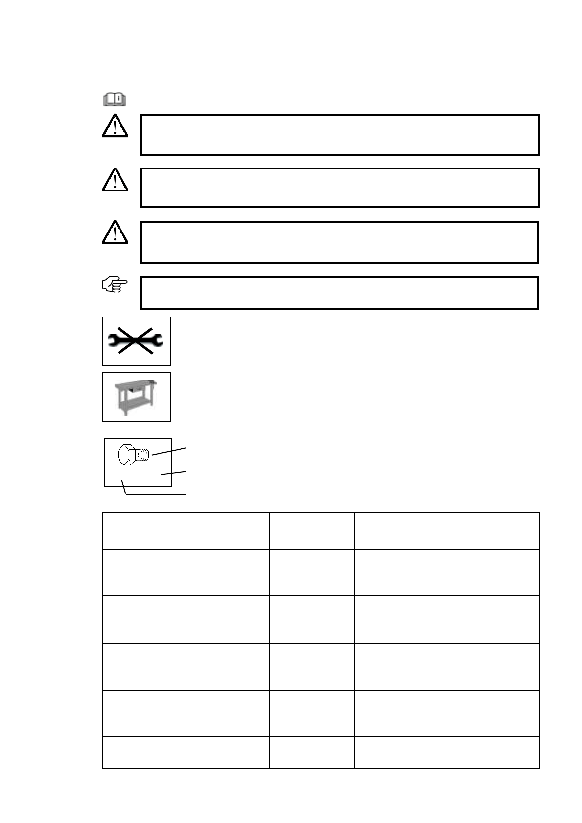
1.2 Warnings and symbols
WARNING:
Indicates a potentially hazardous situation. If this instruction is ignored, there may be a
risk of death or extremely serious injury.
CAUTION:
Indicates a potentially hazardous situation. If this instruction is ignored, there may be a
risk of minor injury.
IMPORTANT:
Indicates operating tips and other useful information.
5
Operating and installation instructions
Work on a workbench
Do not use a tool
DANGER!
Indicates an immediate threat of danger. If this instruction is ignored, there is a risk of
death or extremely serious injury.
Symbol
Type
Quantity
2x M8 x 20
Symbol
Bolt
Washer
Nut
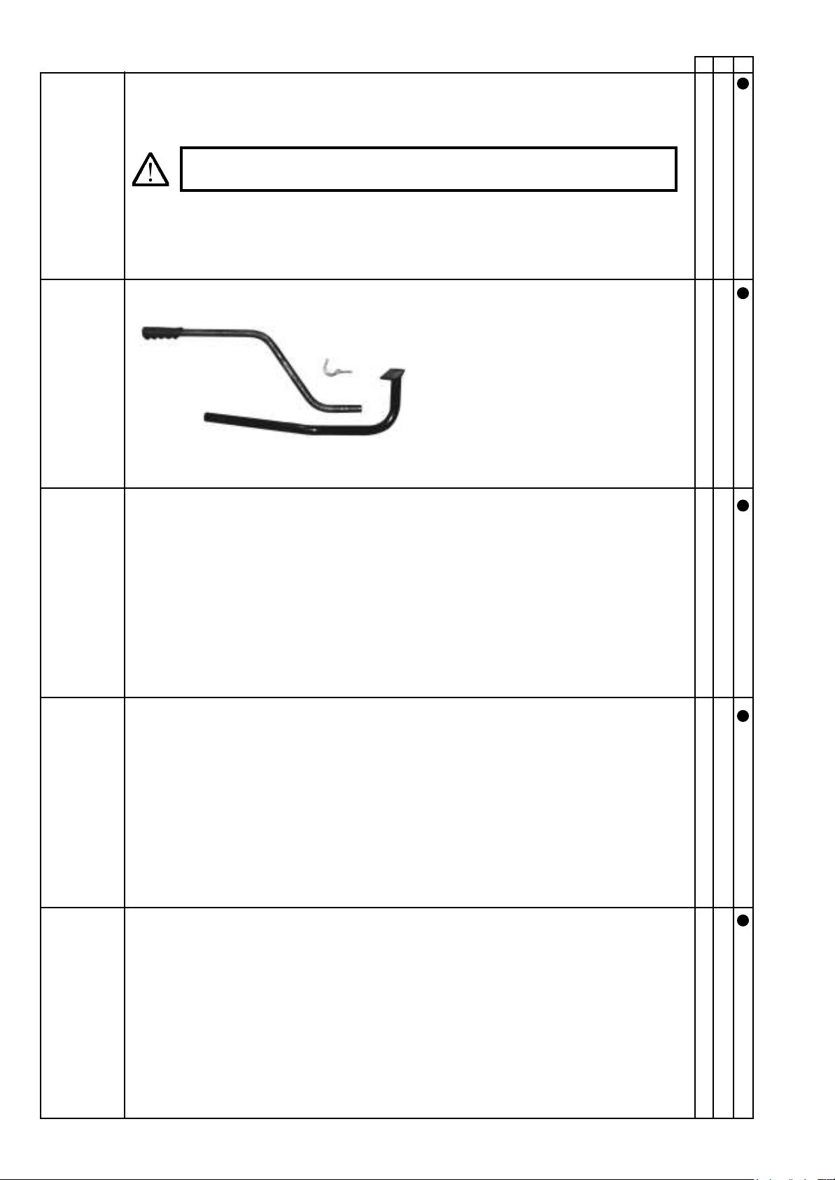
Combination spanner
Hexagon head screwdriver
Screwdriver
Crosshead screwdriver
Type
Examples:
M8 x 16
8,1 - 58 - 5
M8 (L)
8
PZ 2
PH 2
Explanation
M = Metric
S = Diameter in mm
16 = Length in mm
8.1 = Inner diameter
58 = Outer diameter
5 = Material thickness in mm
M = Metric
8 = Inner diameter in mm
(L) = Lock nut
8 = Size in mm
PZ 2 = Pozidriv size 2
PH 2 = Phillips size 2

Basic safety instructions
6
2.2 Organisational measures
e operating and installation instructions must always
be kept ready at the location where the machine is used.
In addition to the operating and installation instruc-
tions, observe and follow the generally valid legal reg-
ulations and any other binding regulations for accident
prevention and environmental protection.
Such obligations may also include handling hazard-
ous substances or making available/wearing personal
protective equipment and complying with road trac
regulations, for example.
Supplement the operating and installation instruc-
tions by instructions as well as site management and
reporting obligations concerning special operational
requirements, for example with regard to work organ-
isation, workows, personnel used, etc.
Any personnel instructed to perform work on the
machine must have read the operating instructions
before starting work, specically the section entitled
"Safety instructions". Reading the instructions aer
work has begun is too late. is applies in particular to
personnel who only work on the machine occasionally,
for example for set-up and maintenance.
At least occasionally, check that the personnel are work-
ing with safety and hazards in mind and are following
the operating instructions.
Personnel must not have long hair which is not tied
back or wear loose clothing or jewellery including rings.
ere is a risk of injury from being caught or drawn
into the machine, for example.
Wear personal protective equipment if necessary or
required by regulations.
Observe all safety and hazard notices on the machine.
Ensure that all safety and hazard notices at/on the
machine can be read in full at all times.
In the event of any modication to the machine or any
change in the machine's performance that may aect
safety, shut down the machine immediately and report
the fault to the responsible specialist dealer.
Do not modify, convert or attach equipment to the
machine without approval from the manufacturer if
this could impair safety. is also applies to tting and
adjusting safety equipment and valves, as well as for
welding on supporting parts.
Use only genuine spare parts from the manufacturer.
ese comply with the technical requirements and
safeguard your warranty and guarantee rights. Adhere
to the prescribed time periods or those indicated in the
operating and installation instructions for recurring
tests/inspections.
Workshop equipment which is appropriate for the work
is mandatory for carrying out maintenance measures.
Make personnel aware of the location of re extinguish-
ers and how to use them.
Comply with the re alarm and reghting procedures.
2.1 Intended use
e product has been constructed using state-of-the-art
technology and in line with the recognised technical
safety regulations. However, use of this product may
still result in the risk of injury or death to the user or
third parties, or of damage to the product and other
material assets.
Only use the product in technically perfect working
order, for its intended use and with safety and hazards
in mind, in compliance with the operating and instal-
lation instructions. In particular, you must immediately
rectify faults that could impair safety or have such faults
rectied immediately by a third party.
e product is exclusively intended to be installed on
the machines approved by the manufacturer and is
intended for the accessories approved by the manufac-
turer. Any other or additional form of use, for example
use in conjunction with self-constructed accessories,
shall be regarded as non-compliant with the intended
use. is product is solely intended for sweeping ap-
plications as part of grounds maintenance and winter
road maintenance. Any other or additional form of use
is considered non-compliant with the intended use.
For example, the product must not be used to sweep
animal feed. Bristles can come loose and be consumed
by animals, harming the animal. e manufacturer/
supplier shall not be held liable for any damage or loss
suered as a result. e risk is borne solely by the user.
Intended use also includes complying with the oper-
ating and installation instructions and adhering to the
inspection and maintenance conditions.
is sweeper may only be operated with brushes that
have been approved by the manufacturer.
e implement is solely intended for clearing dirt on
roads, foliage and snow. Any other applications are
not permitted.
Unauthorised operators:
Persons who are not familiar with the operating in-
structions, minors and persons under the inuence
of alcohol, drugs or medication must not operate the
implement.
2 Basic safety instructions
7
2.3 Personnel selection and qualications; basic obligations
Work on/with the product may only be carried out by
reliable personnel. Observe the legal minimum age.
Only use trained or instructed personnel and clearly
dene the responsibilities of the personnel for opera-
tion, set-up, maintenance and repair.
Ensure that only authorised personnel work on the
product.
Only allow personnel who are yet to complete training,
instruction and induction or who are still completing a
general apprenticeship to carry out work on the prod-
uct under the constant supervision of an experienced
person.
Work on the product's electrical equipment may only
be carried out by a qualied electrician or by trained
personnel under the guidance and supervision of a
qualied electrician in accordance with electrical en-
gineering regulations.
Work on chassis, braking and steering systems must
only be carried out by qualied personnel trained for
such work.
Only personnel who possess specic knowledge of and
experience in hydraulics are allowed to carry out work
on hydraulic equipment.
Clean the implement regularly, particularly in the ex-
haust and engine area. Otherwise, there is an increased
risk of re.
Basic safety instructions
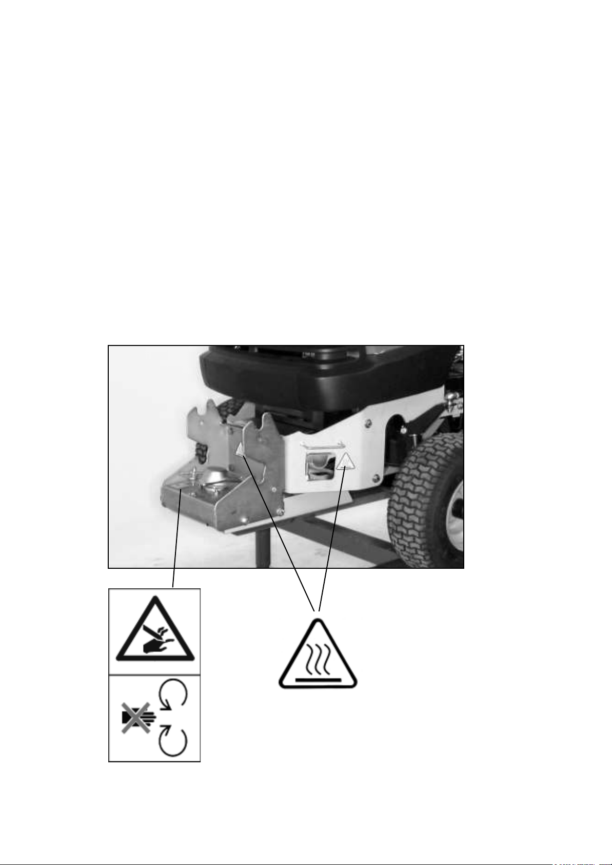
2.4 Position of safety stickers and labels
Caution:
Hot surface
Do not open the pro-
tective equipment,
risk of crushing

1
9
Illustration of the machine and danger zone
4 Illustration of the machine and danger zone, component description, position of safety stickers and labels
1. Danger zone
2. Lever for raising and lowering the sweeper
3. Swivelling lever for laterally adjusting the sweeper brushes
4. Ball handle for adjusting the height of the brushes
5. Mount for the debris container
6. Support wheel
7. Sweeper brush
8. Serial number
9. Machine designation
10. Manufacturer name
11. Weight
12. Year of construction
13. CE marking
14. Engine power
15. Engine manufacturer
16. Manufacturer address
17. Part number
A hazard is posed by ejected particles
while the engine is running – keep a
safe distance.
Max. speed 5 km/h
Before putting the machine
into operation, read and
take note of the operating
and safety instructions.
10
9
15
14
11
12
13
16
17
8
2
3
4
5
76
Ø = 15 m
Installation
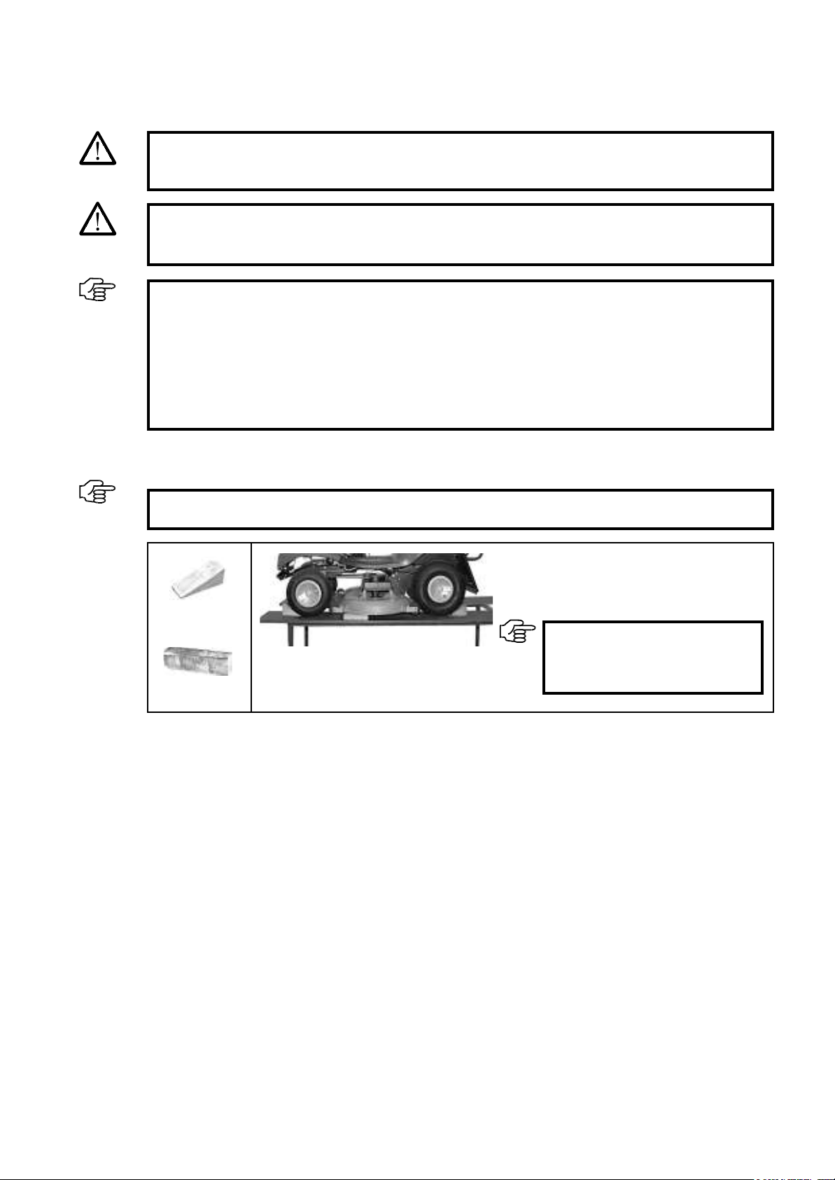
Installation should be performed on a height-adjustable work platform in accordance with the following instruc-
tions.
Lower the mower on to timber.
Secure the lawn tractor against rolling away by
using wheel chocks.
11
2x
5.1 Preparatory measures prior to installation
5 Installation
1x
IMPORTANT:
Follow the operating instructions
provided by the manufacturer for
this.
IMPORTANT:
Comply with the safety regulations for the work platform.
DANGER!
There is an increased risk of injury near running drives. Follow the safety instructions.
IMPORTANT:
The construction sets supplied must be checked to ensure that they are complete using the spare
parts list in these instructions.
The quick-change system should only be installed by a specialist dealer of engine units.
Before you begin, acquire an overview of the installation sequence and the required parts and tools.
The machine must be clean and in technically correct working order.
Follow the lawn tractor manufacturer's safety instructions and operating instructions.
WARNING:
Switch off the engine and allow it to cool down. The machine must be secured to prevent it from being
started inadvertently. Remove the ignition key and activate the parking brake.

12
Dear valued customer,
Models are continuously being updated by the lawn tractor and implement manufacturers in line with technolog-
ical progress. As a result, descriptions or illustrations in these instructions may differ from the actual conditions
on the lawn tractor.
Select one of the columns below on the basis of your mounting frame.
Column A = Attachment parts without quick-change mechanism,
for securely attached accessories
Column B = Attachment parts with quick-change mechanism,
for non-driven implements (e.g. clearing blade)
Column C = Attachment parts with quick-change mechanism with drive,
for driven implements (e.g. sweepers) and
for non-driven implements
1) During installation, only those steps which are marked with a point •
in the selected columns have to be carried out. Highlight the column that applies using a highlighter.
2) The sequence given in the installation instructions must be complied with.
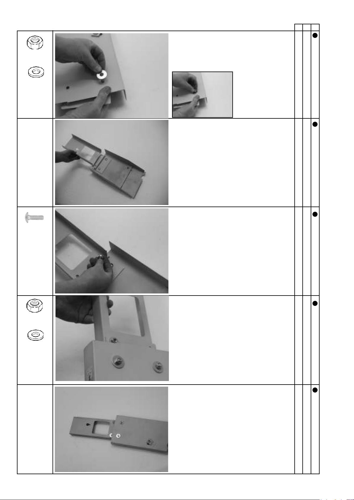
Installation
5.2 Installation
DANGER!
It is necessary to remove protective equipment in order to install attachment parts. You must there-
fore ensure that this equipment is reattached after installation is complete. This is why none of the
following work steps can be ignored.
DANGER!
The installation procedure described below must only be performed by the specialist dealer.
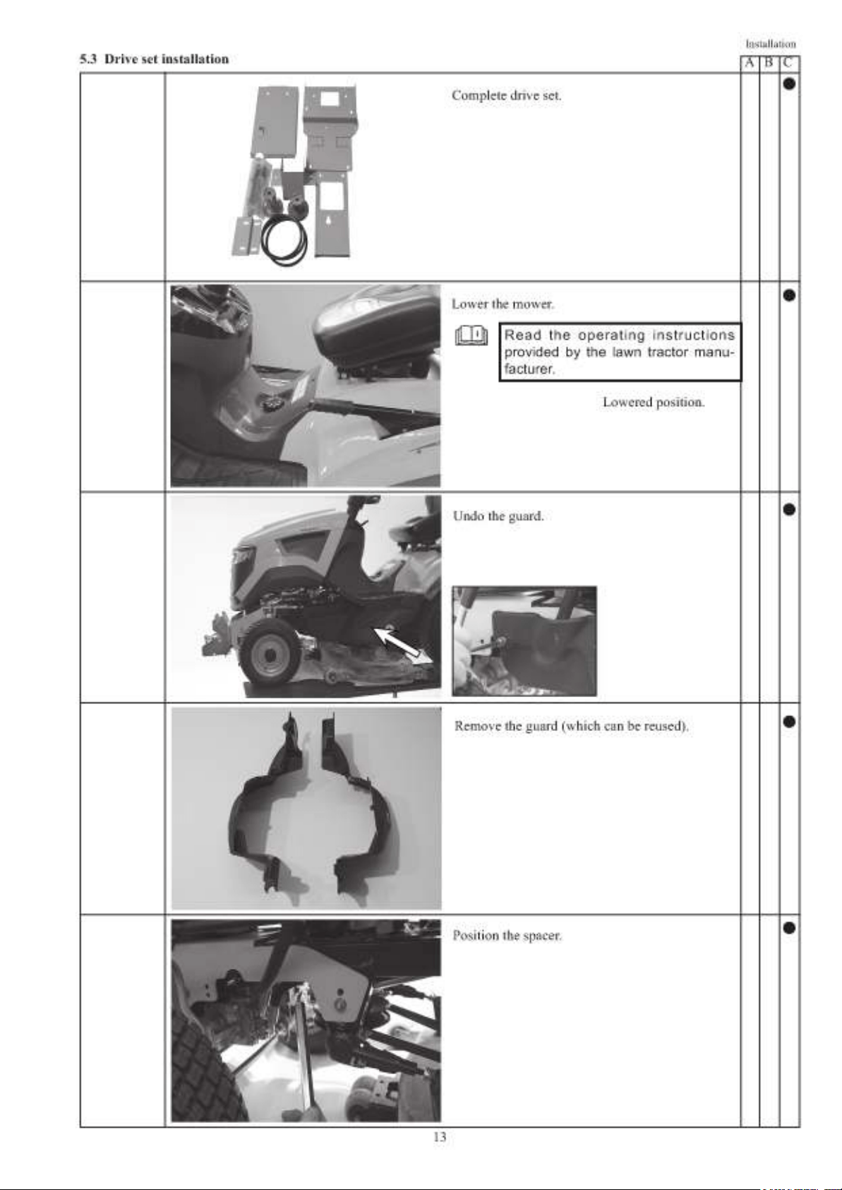
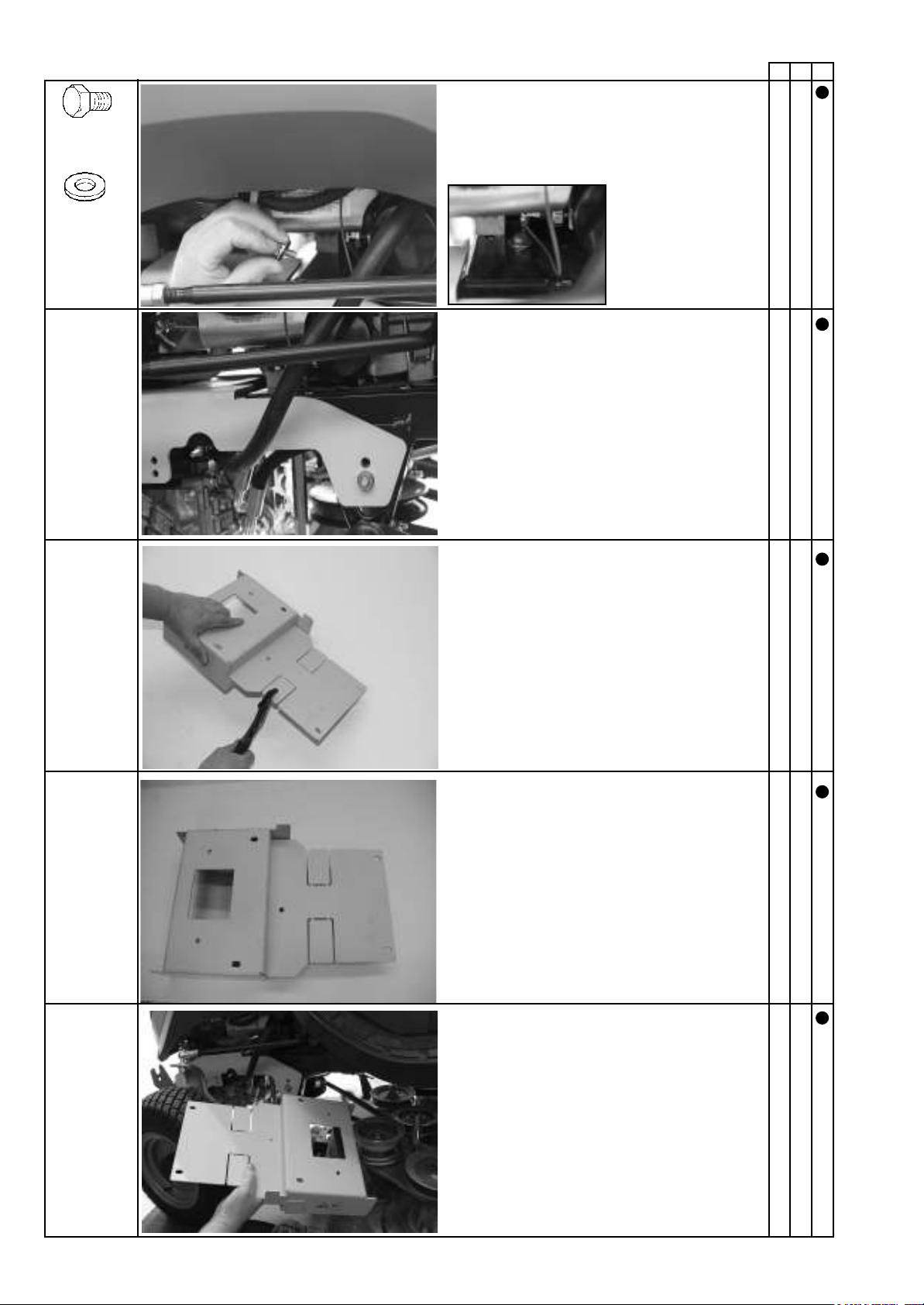
Push the bolt with washer through the hole.
On a (2wd) rear-wheel drive tractor:
Remove parts.
Position the bracket.
Installation
14
A B C
2x M8 x 16
2 x 8.4-25-2
On a (4wd) all-wheel drive tractor:
Do not remove parts.
Loosely pre-assemble the spacer.
Tighten all bolts.
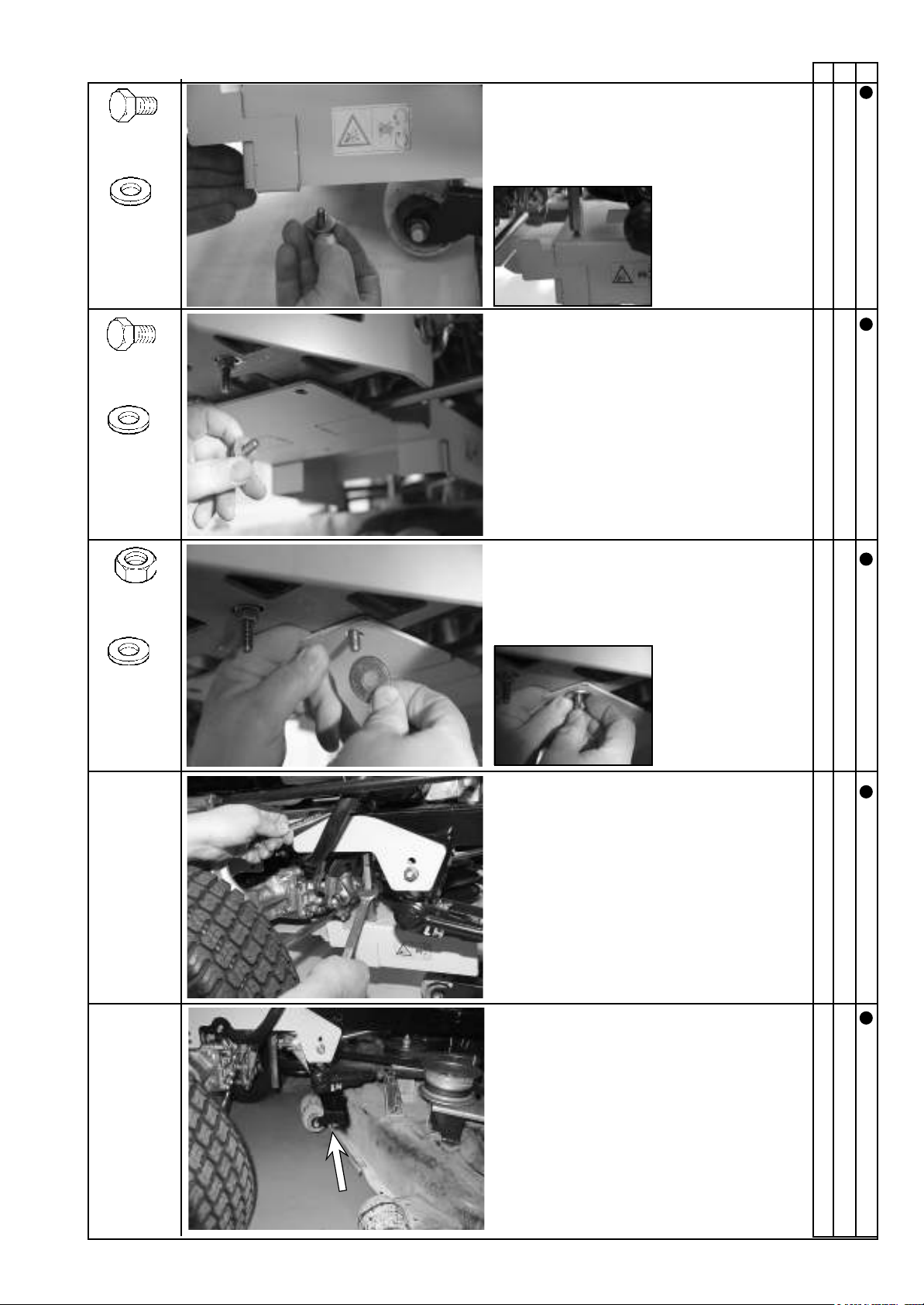
Turn the nut with washer on the bolt.
Push the bolt with washer through the hole.
Remove the castors.
Installation
15
A B C
Push the bolt with washer through the drilled
hole and screw it into the spacer.
2x M8 x 16
2 x 8.4-25-2
2x M8 x 20
2x
2 x 8.4-25-2
2 x 8.4-25-2
2x M8
Installation
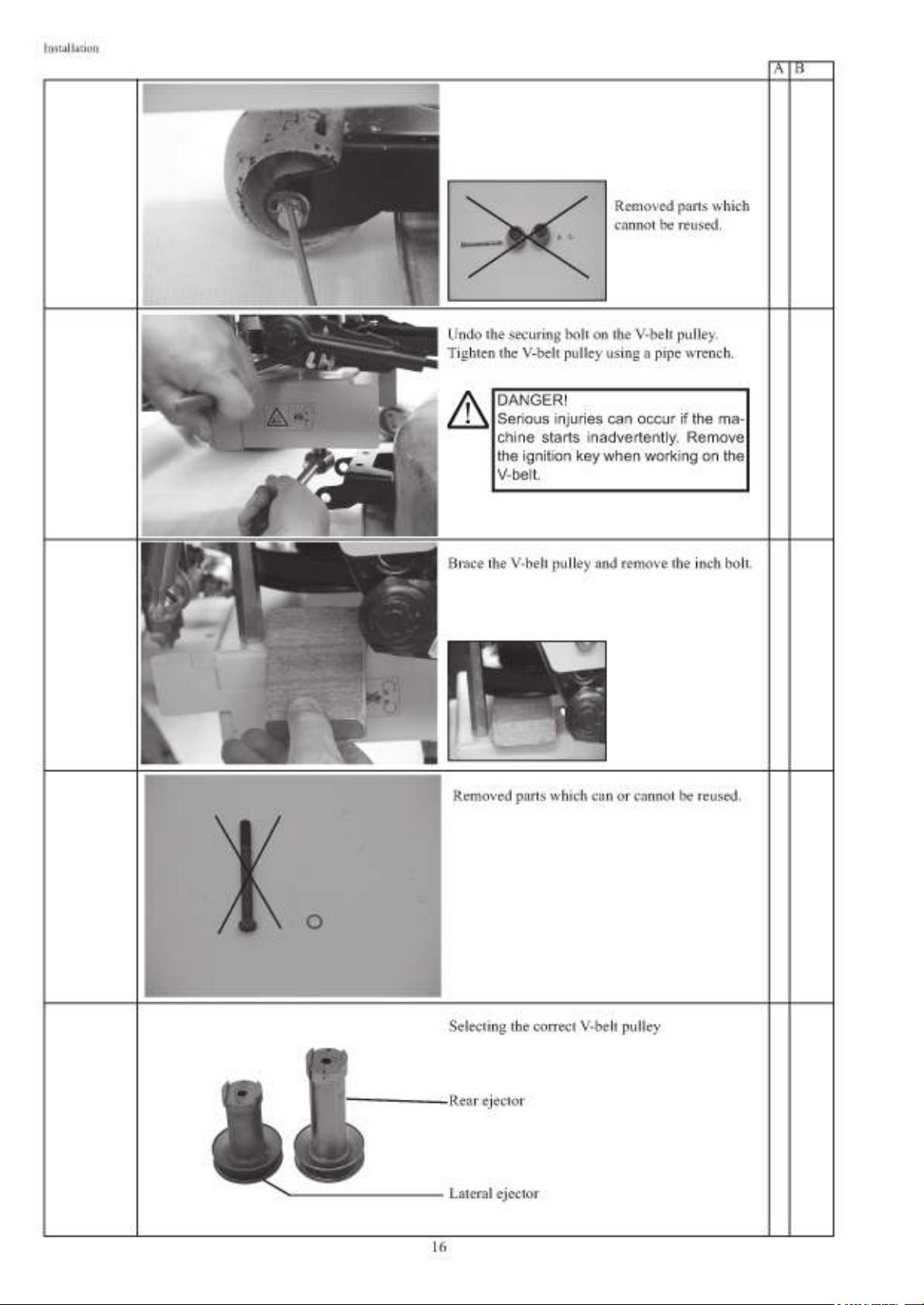
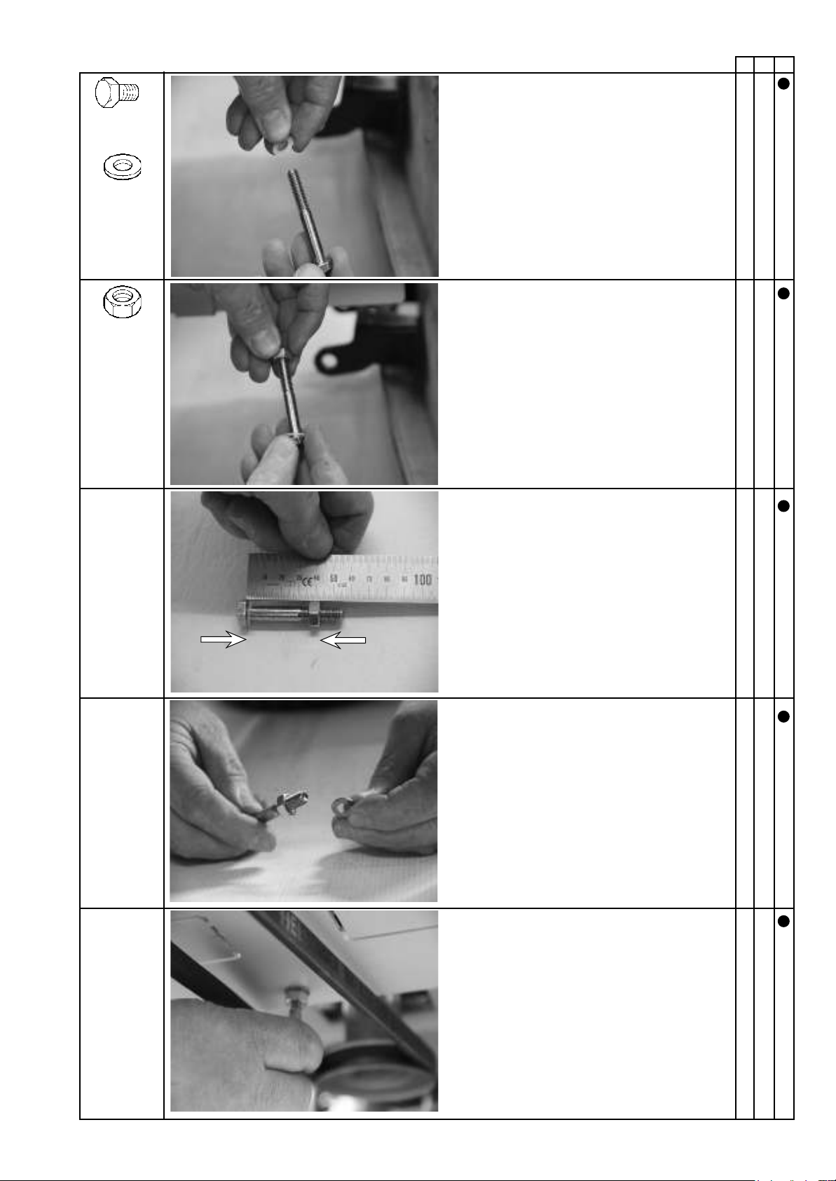
17
A B C
1x 7/16" x
20 UNF x
3 1/2“
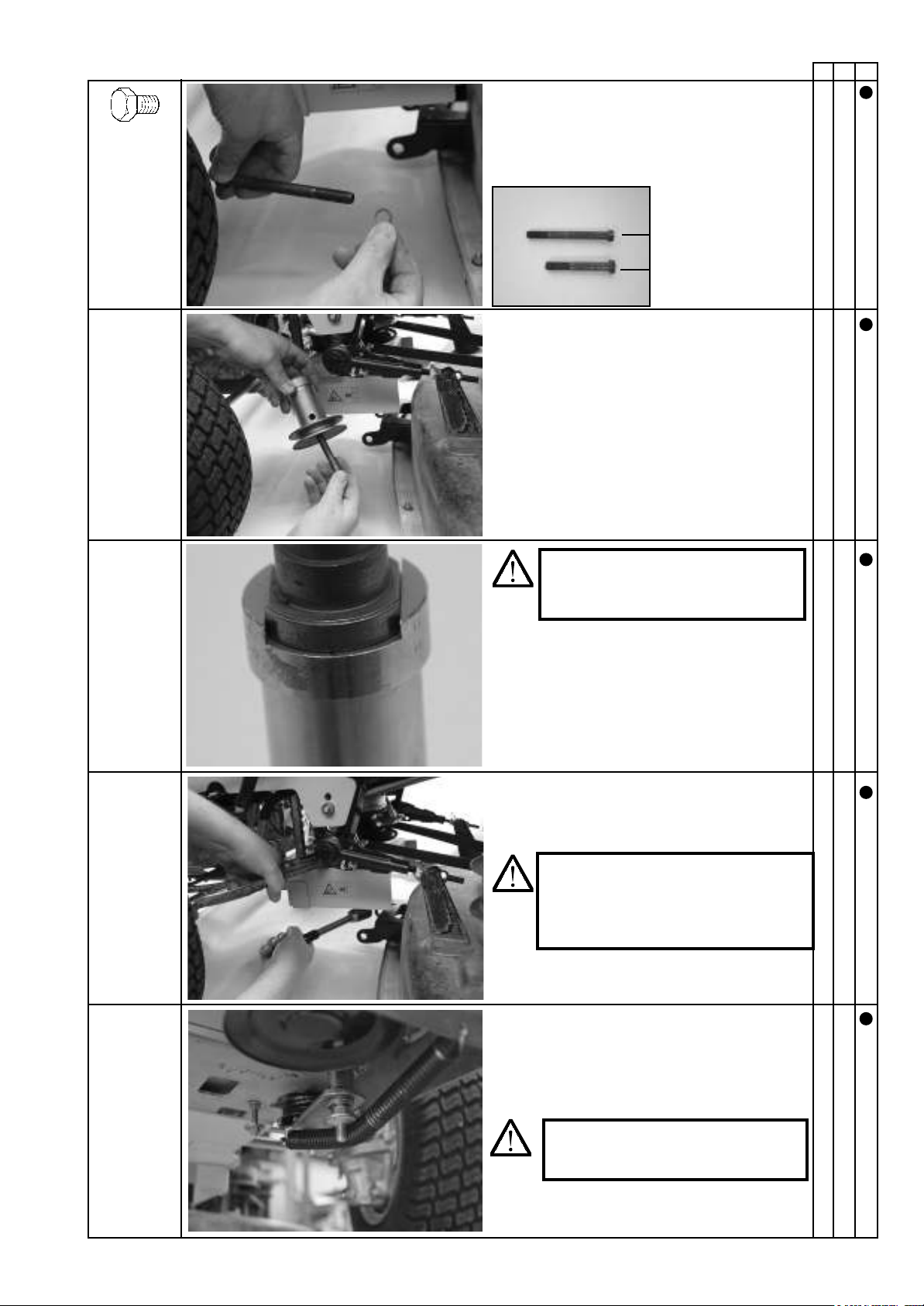
Push the washer onto the bolt.
Lateral ejector
Rear ejector
Push the bolt with washer through the hole.
Install the V-belt pulley using the inch bolt and
tighten it.
Move the V-belt tensioner against the force of the
spring and place the V-belt on the quick-release
coupling's V-belt pulley.
IMPORTANT:
Tightening torque: 55-60 Nm. Tighten
the V-belt pulley using a hook wrench
to prevent it from turning.
DANGER!
Only rotate the V-belt pulley if the ig-
nition key has been removed.
CAUTION!
Take care to mount the V-belt pulley
correctly.
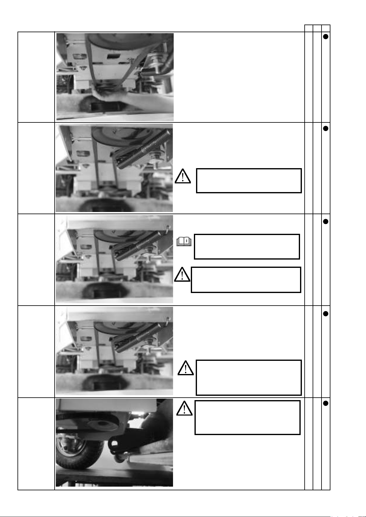
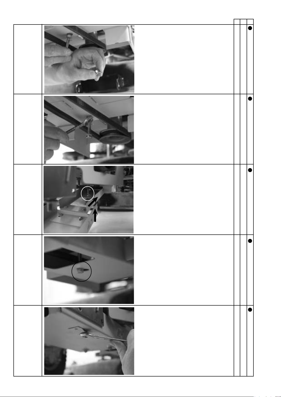
Installation
18
A B C
The V-belt is then placed on the V-belt pulley below
the engine.
Start the engine.
WARNING:
Risk of injury! Do not reach into the
V-belt while it is in operation.
Read the operating instructions
provided by the lawn tractor manu-
facturer.
Check that the V-belt drive is running correctly
(V-belt pulley running true) – see the information
on installing the V-belt pulley. Check that the V-belt
is running freely and whether the edges of the
V-belt are in contact with the V-belt idler pulley,
optimising the alignment if necessary.
DANGER!
Switch the engine off again.
Keep a safe distance from hot sur-
faces.
Release the tension spring so that the V-belt tensioner
comes into operation.
CAUTION:
The spring is tensioned.
Risk of crushing.
CAUTION!
6XI¿FLHQW FOHDUDQFH PXVW EH PDLQ-
tained between the mower and V-belt
pulley.
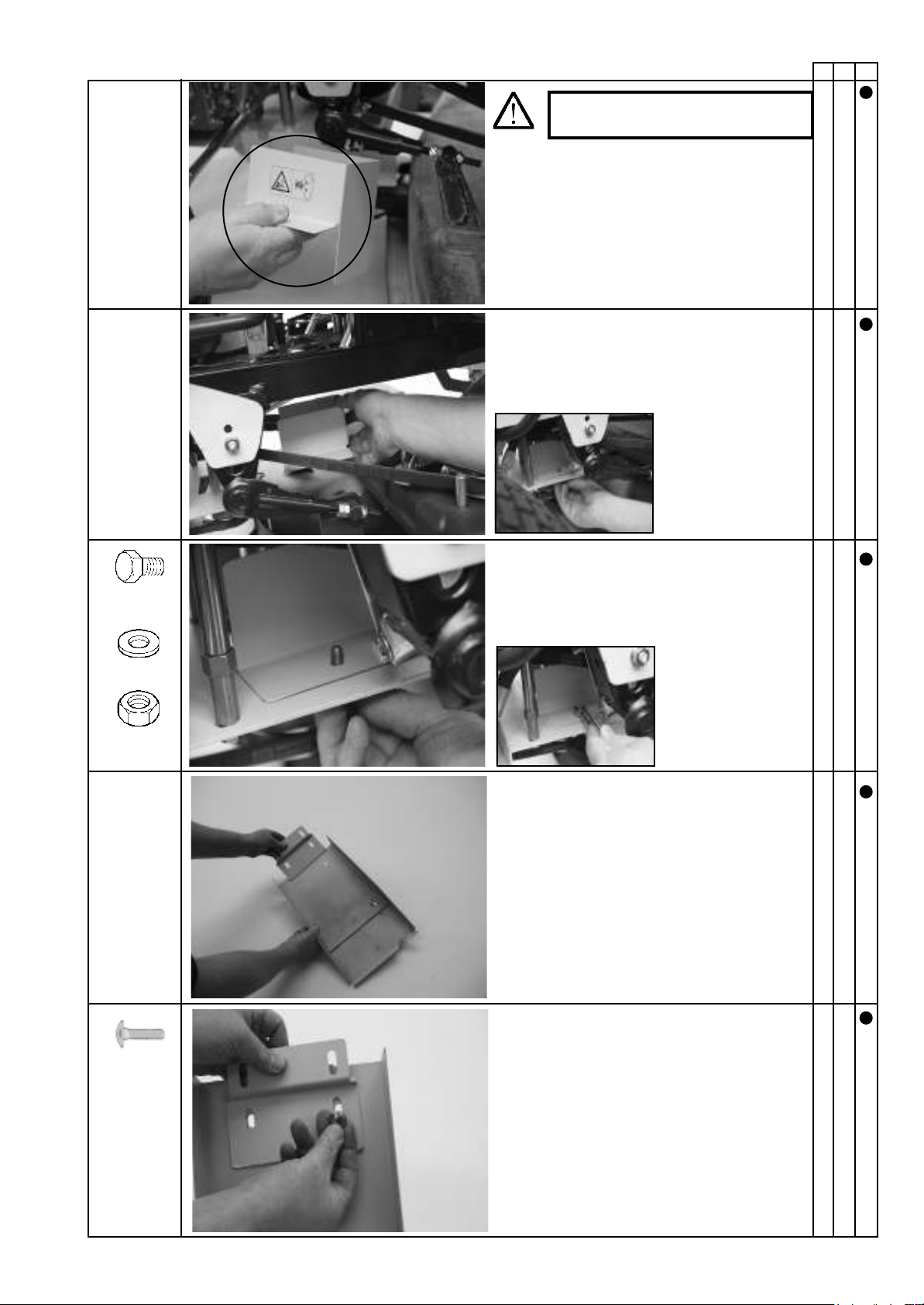
Installation
19
A B C
CAUTION!
Only use on rear ejectors.
Push the bolt through the drilled hole in the
¿QJHUJXDUG
2x M8 x 16
On rear ejectors only
Position the guard.
3RVLWLRQWKH¿QJHUJXDUG
On rear ejectors only
Push the bolt with washer through the drilled hole
in the bracket.
2x M8x16x20
2x 8.4-16-1.6
Turn the nut with
washer on the bolt.
Tighten the bolts.
2x M8
Installation
20
A B C
Push the nut with washer onto the bolt.
2x 9-28-3
2x M8
Position the guard.
Push the bolt through the drilled hole in the
guard.
Turn the nut with washer on the bolt.
2x M8 x 16
2x 9-28-3
2x M8
Installation
21
A B C
1x 8.1-14-1
1x M8 x 55
With a clearance of approx. 42 mm.
Push the washer onto the bolt.
Position the bolt.
approx. 42
mm
Turn the nut on the bolt.
1x M8
Installation
22
A B C
Turn the nut with washer on the bolt.
Tighten the bolt.
Position the guard.
Tighten all bolts.
Installation
23
A B C
&RUUHFWO\LQVWDOOHG¿QJHUJXDUG
Reinstall the removed guard.
Tighten the bolts.
Completely installed mounting frame with drive.
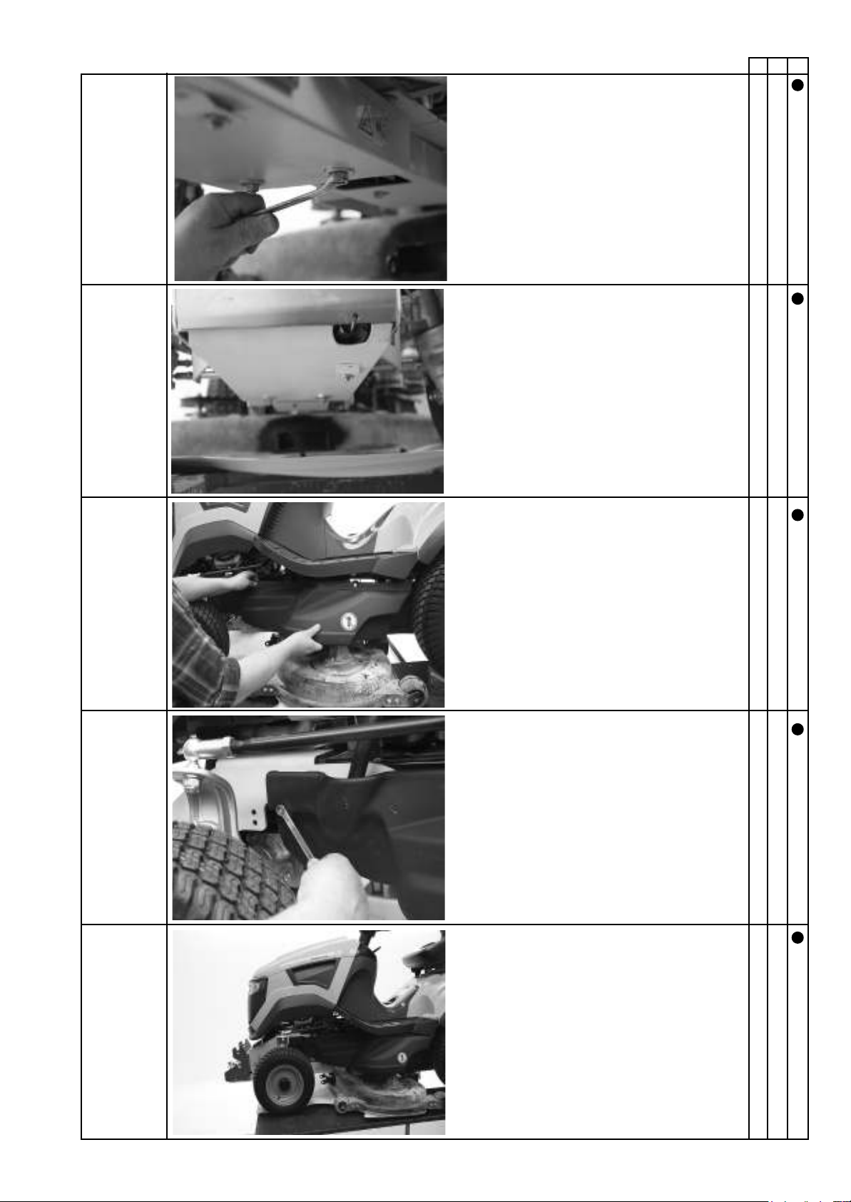
Installation
24
A B C
DANGER!
(QVXUHWKDWDOOSURWHFWLYHHTXLSPHQWLVVHFXUHO\¿WWHG
Assemble the operating lever. To do so, refer to
the operating instructions for the attachment.
25
5.4 Sweeper attachment installation
Remove the nuts on the right- and le-hand supports.
Remove the supports on the right and le.
Sweeper without supports.
Installation
Parts that can be reused, e.g. for storing the sweeper.
IMPORTANT:
Follow the safety instructions.
Before you begin, acquire an overview of the installation sequence and the required parts and tools.
2x SW 19
Installation
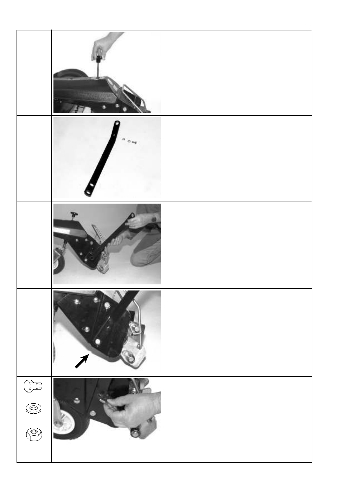
26
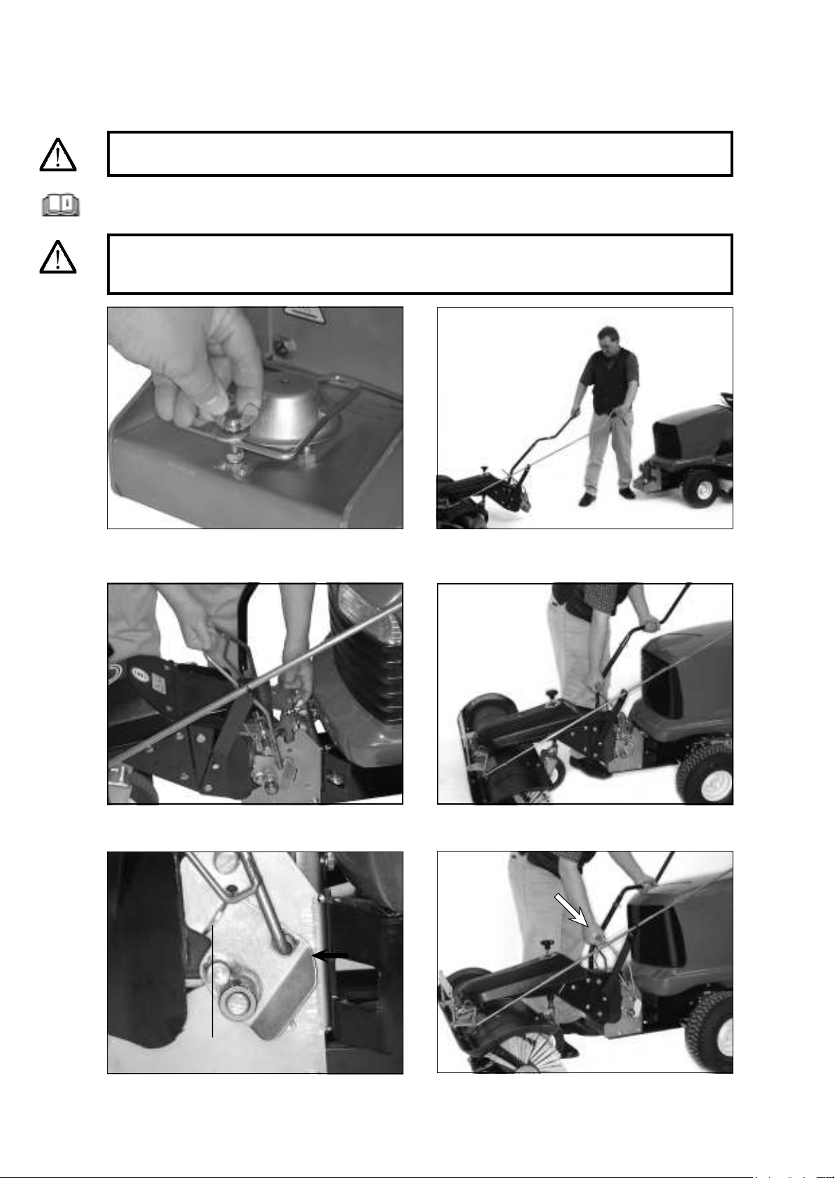
Connect the guide to the pin.
Secure the guide to the support with a bolt, washer and nut.
Ready the guide.
Position the guide on the support.
1x M8 x 16
1x 8.4-21-4
1x M8
Screw in the ball handle for adjusting the height of the support
wheel.
Installation
27
Tighten the bolt.
Correctly secured guide.
Ready the liing linkage.
Note: e liing linkage is part of the mounting frame.
2x SW 13
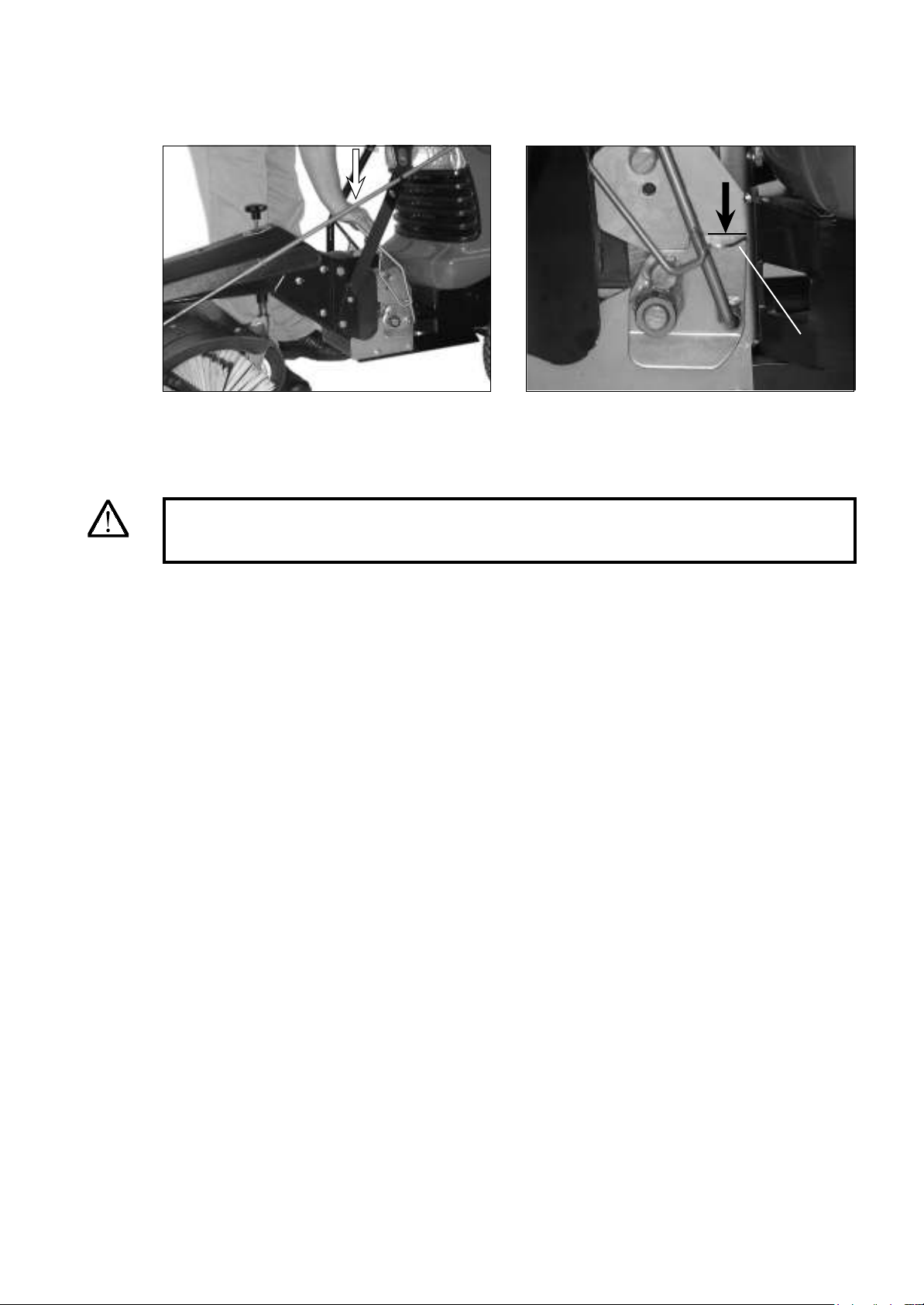
Push the bolt through the hole in the tab.
Turn the washer and nut on the bolt.
1x M12 x 30
1x 13-24-2
1x M12
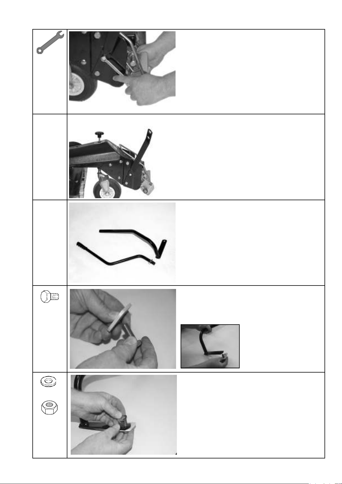
Installation
28
Push the linkage onto the pin.
Correctly positioned linkage.
Secure the linkage with an R-pin.
Correctly installed linkage.
Installation
29
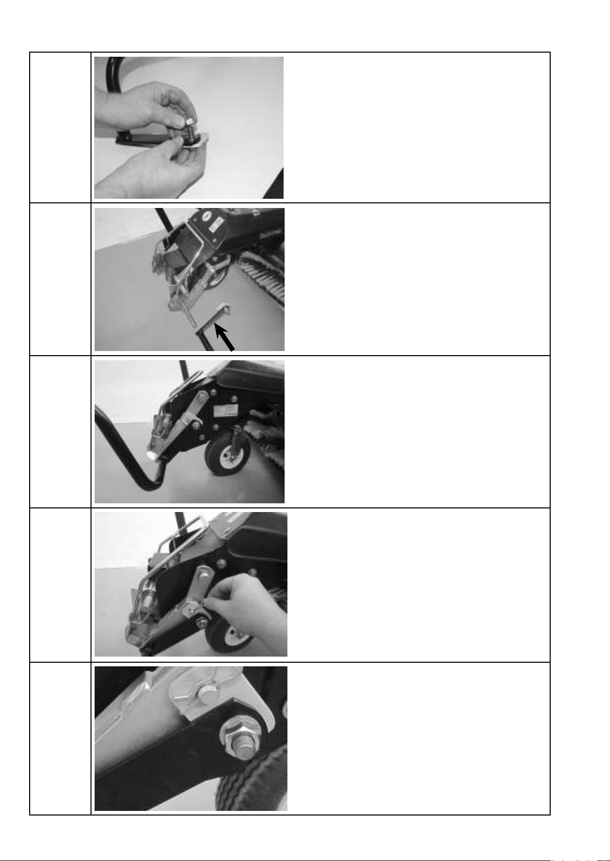
Insert the extension pipe.
Secure the pipe with a linch pin.
Correctly installed pipe with linkage.
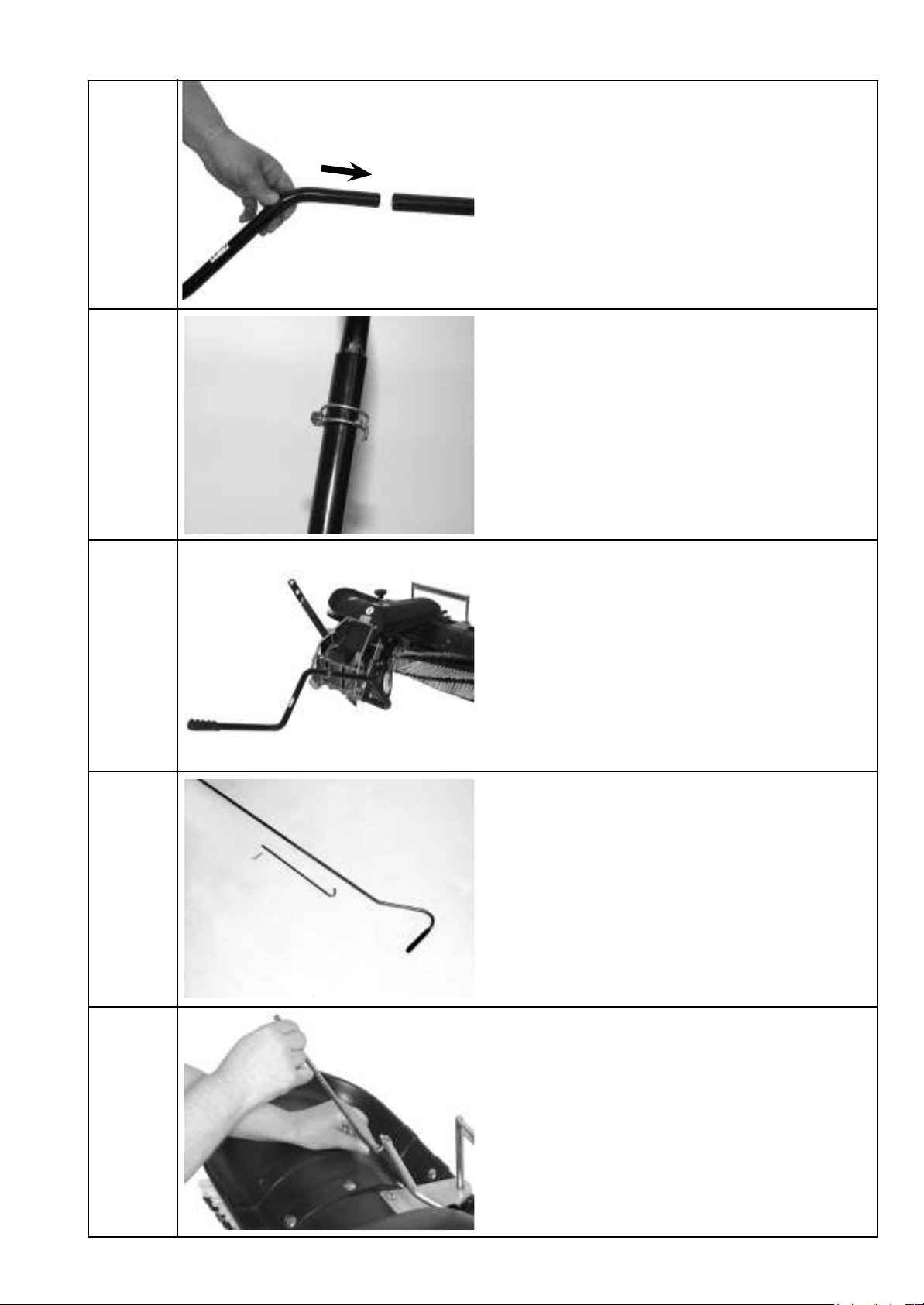
Ready the control linkage.
Insert the hook into the rotary unit from below.
Installation
30
Secure the hook and control linkage using an R-pin.
e control rod should be within comfortable reach of
the driver's seat.
Hook mounted on the rotary unit.
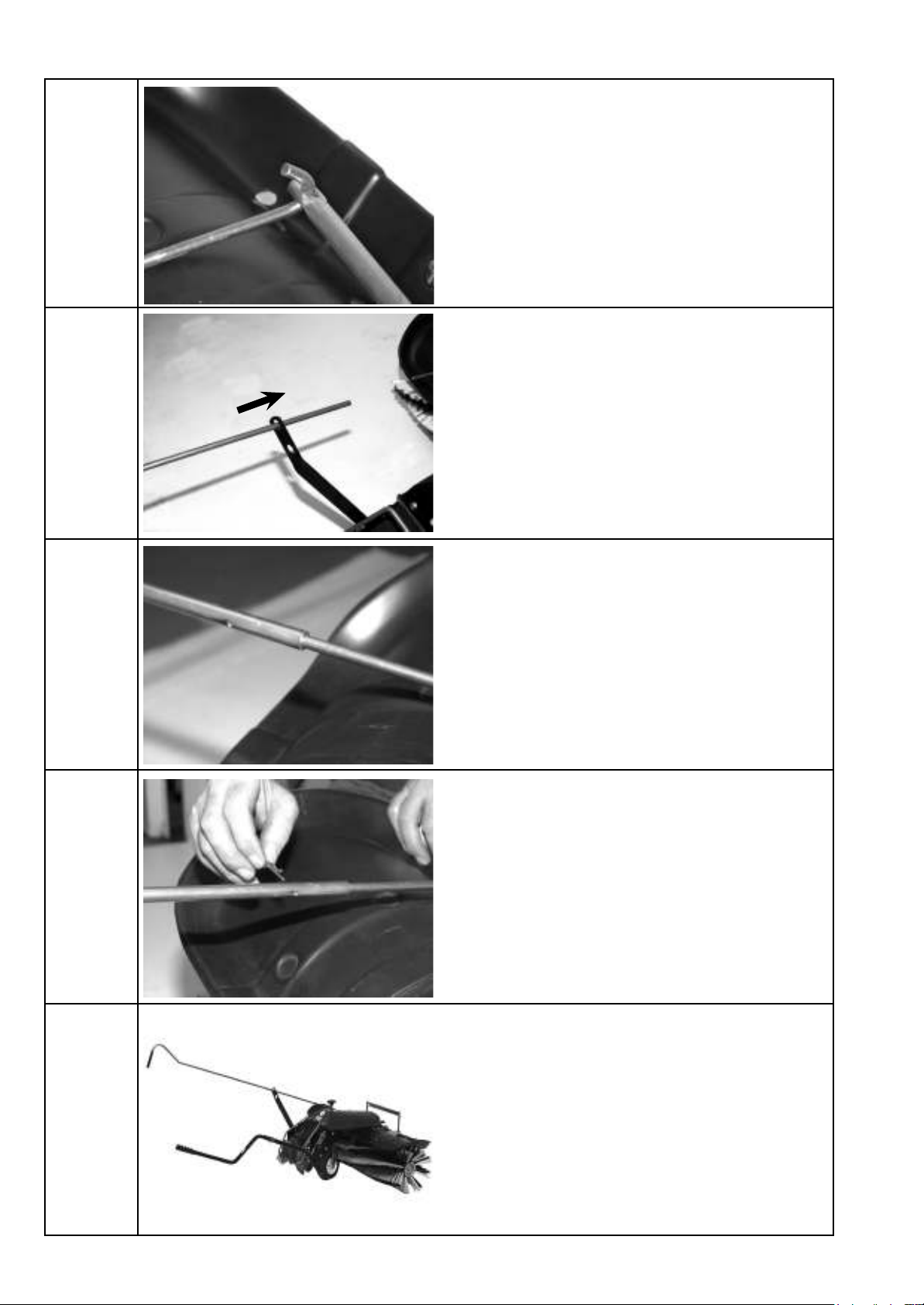
Push the control rod through the guide.
Interlock the hook and control rod.
Correctly installed sweeper.
6.1 Basic safety instructions for normal operation
6 Start-up
Never operate the machine in a manner that could
compromise safety.
Before beginning work, familiarise yourself with the
work environment at the location where the machine
is used. The work environment includes, for example,
REVWDFOHV LQWKH ZRUNDQGWUDI¿FDUHDWKHORDGEHDULQJ
FDSDFLW\ RIWKH ÀRRUDQGWKHUHTXLUHG PHDQV RIFRUGRQ-
ing the location where the machine is used off from
WKHSXEOLFWUDI¿FDUHD
Take appropriate measures to ensure that the machine is
only operated in a safe and fully functional condition.
Only operate the machine when all protective equip-
ment and safety-critical equipment, for example
detachable protective equipment, sound-insulating
equipment and extraction equipment, is present and
in proper working order.
Always check for externally visible damage and defects
before using the machine. Report any changes that may
have occurred (including changes in performance) to
the specialist dealer immediately. Shut down the ma-
chine immediately and secure it if necessary.
In the event of a malfunction, shut down and secure
WKH PDFKLQH LPPHGLDWHO\+DYH IDXOWVUHFWL¿HG LP-
mediately.
Only start the machine from the driver's seat.
Switch the machine on and off in accordance with the
installation instructions, observing the control displays.
Before switching on/starting up the machine, ensure
that no one can be endangered by the machine starting
up.
Before travelling with the machine or beginning work,
check that the brakes, steering, signal and lighting
systems are fully functional.
Before moving the machine, always check that the
accessories are securely in place.
When driving on public roads and paths and in public
SODFHVFRPSO\ZLWKWKHDSSOLFDEOHURDGWUDI¿FUHJX-
lations and bring the machine into a condition which
LVSHUPLWWHGE\URDGWUDI¿FUHJXODWLRQVLQDGYDQFH
,Q SRRUYLVLELOLW\RULQWKHGDUNDOZD\V HQVXUHVXI¿-
cient lighting.
Always maintain an adequate distance from pit edges
and slopes.
Prohibit any manner of working that may impair the
stability of the machine.
The machine must not be used on slopes with a gradient
of more than 10° (17%).
'R QRW GULYH DFURVVVORSHV DOZD\VWUDQVSRUW ZRUN
equipment and loaded goods close to the ground,
particularly when descending hills.
Always adapt your driving speed to the conditions
on sloping terrain. Never change to a lower gear on a
VORSH\RXVKRXOGGRWKLVEHIRUH\RXUHDFKWKHVORSH
Upon leaving the machine, always secure it against
accidentally rolling away and unauthorised use.
Start-up
31
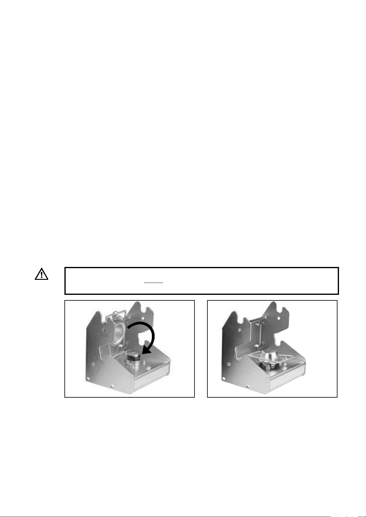
&ORVHWKHSURWHFWLYHÀDS
6HFXUHWKHSURWHFWLYHÀDSXVLQJWKHEROW
WARNING:
Before using the lawn tractor without an implement, cover the dog clutch on the quick-release coupling
with the guard and secure using the bolt.
6.2 Coupling and uncoupling the sweeper
Start-up
32
1) Undo the wing bolt on the quick-change mecha-
nism guard.
2) Pull the sweeper over to the lawn tractor.
3) Li the guard and position the sweeper.
5) Tab before locking.
4) Mount the sweeper.
6) Push the coupler handle down at an angle.
DANGER!
Switch off the engine. Secure the lawn tractor against being started inadvertently or rolling away.
WARNING:
If the drive set is not used, the guard on the quick-change mechanism with drive must be secured
using the wing bolt.
Tab
Read the operating instructions provided by the lawn tractor manufacturer.
Start-up
7) Locking the sweeper 8) Correctly locked. e tab must be pushed until the
notch is level.
Tab
33
To uncouple the sweeper attachment, follow the instructions in reverse order.
CAUTION:
Before using the sweeper you must always ensure that the quick-change mechanism is safely locked.
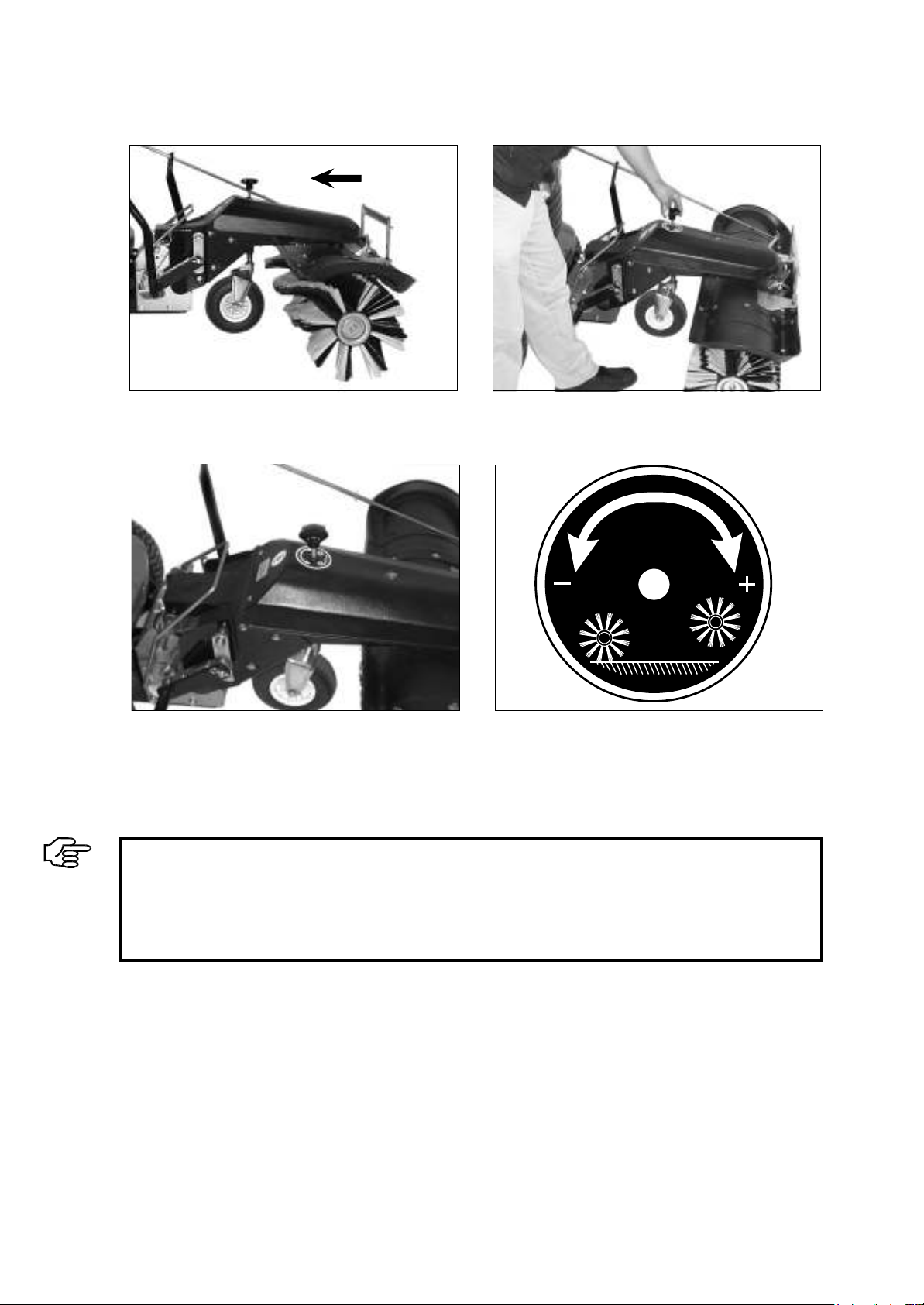
6.3 Brush pressure
1) e ball handle for adjusting the brush pressure is
located above the support wheel.
2) e height of the support wheel is adjusted by
turning the ball handle.
3) Optimal brush pressure: Lower the brush until it is
just touching the oor. en turn the handle all the
way round three more times in an anti-clockwise
direction (towards the (-) arrow).
4) Turning clockwise (+): Raise the brush
Anti-clockwise (-): Lower the brush
34
IMPORTANT:
If you are using a badly worn brush or working on cobblestones, lower the brush by an addi-
tional complete turn. Please note: Excessive brush pressure impairs cleaning effectiveness
because the bristles will be too bent.
Reduce the pressure on the brushes after each use. Raise the brushes.
Start-up
Start-up
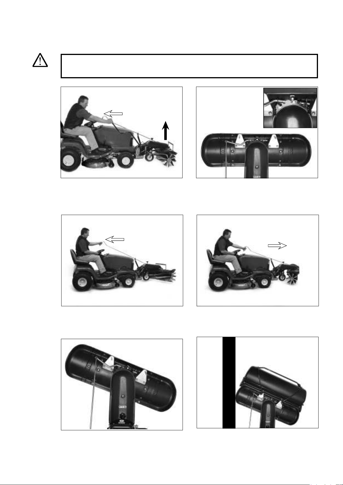
6.4 Setting the ejection direction
1) To adjust the ejection direction with ease, please
li the sweeper.
2) e ejection direction can be set to one of ve
options. In this example, debris will be ejected
at the front. is position means that debris will
accumulate in front of the brush. We recommend
lateral brush positions.
35
5) e debris will then be deposited laterally and swept
aside. is setting is particularly useful when clear-
ing snow from pavements. In this example, debris
will be ejected on the right.
4) Pushing the control rod will change the ejection
direction to the right. Allow the rod to lock back
into place securely.
3) Pulling the control rod will change the ejection
direction to the le. Allow the rod to lock back
into place securely.
WARNING:
Ensure that no persons or property are located in the danger zone, as otherwise this could
result in injury or material damage.
6) We recommend a lateral setting if the debris con-
tainer is used. is allows the operator to sweep
adjacent to a wall (e.g. of a building or against the
curb), even with the debris container.
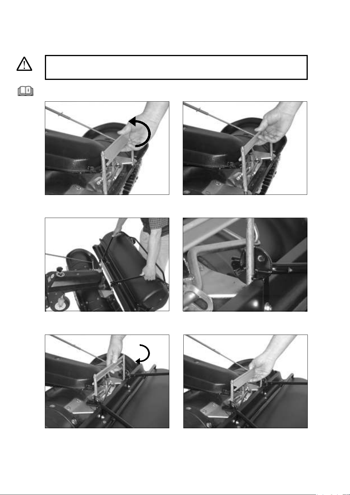
6.5 Debris container
1) Turn the locking mechanism backwards.
2) Locking mechanism in the back position.
Start-up
36
4) Debris container in the bottom position.
3) Place the debris container on the mounting rods
and push it downwards.
5) Turn the locking mechanism forwards. 6) e debris container is locked.
DANGER!
Switch off the engine. Secure the lawn tractor against being started inadvertently or rolling away.
Read the operating instructions provided by the lawn tractor manufacturer.
7) Ensure that the top rubber lip of the container is located below the sweeper brush cover.
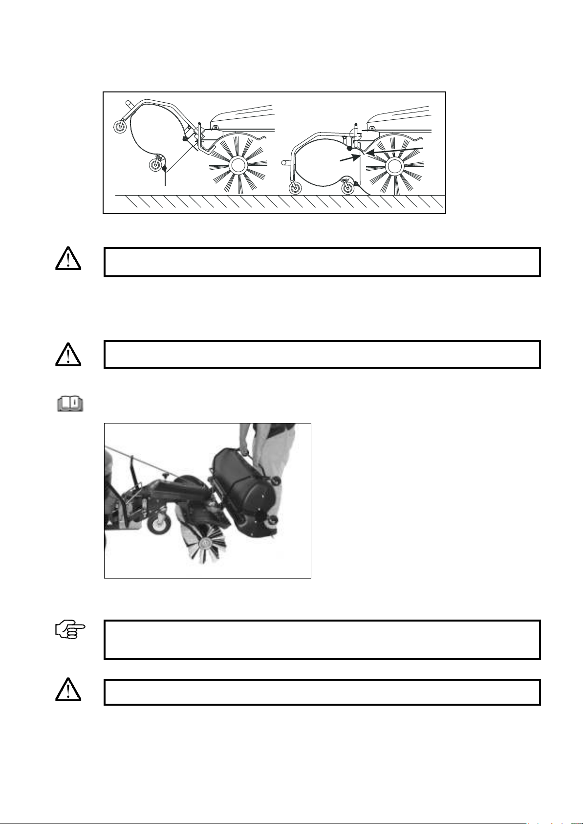
1) Li the front of the debris container frame. e
debris will fall out.
37
Start-up
6.6 Emptying the debris container
CAUTION:
Never lift the sweeper when the debris container is full as this may damage the lawn tractor.
DANGER!
Switch off the engine. Secure the lawn tractor against being started inadvertently or rolling away.
Read the operating instructions provided by the lawn tractor manufacturer.
IMPORTANT:
Please contact the responsible waste disposal services for information on how to properly dispose
of the debris.
CAUTION:
Never lift the sweeper when the debris container is full as this may damage the lawn tractor.
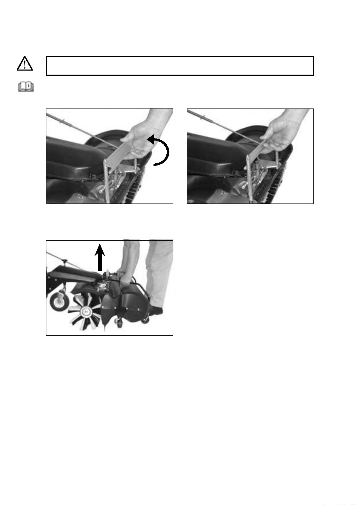
6.7 Removing the debris container
Start-up
2) Locking mechanism turned backwards.
38
1) Turn the locking mechanism backwards.
DANGER!
Switch off the engine. Secure the lawn tractor against being started inadvertently or rolling away.
Read the operating instructions provided by the lawn tractor manufacturer.
3) Remove the debris container vertically.
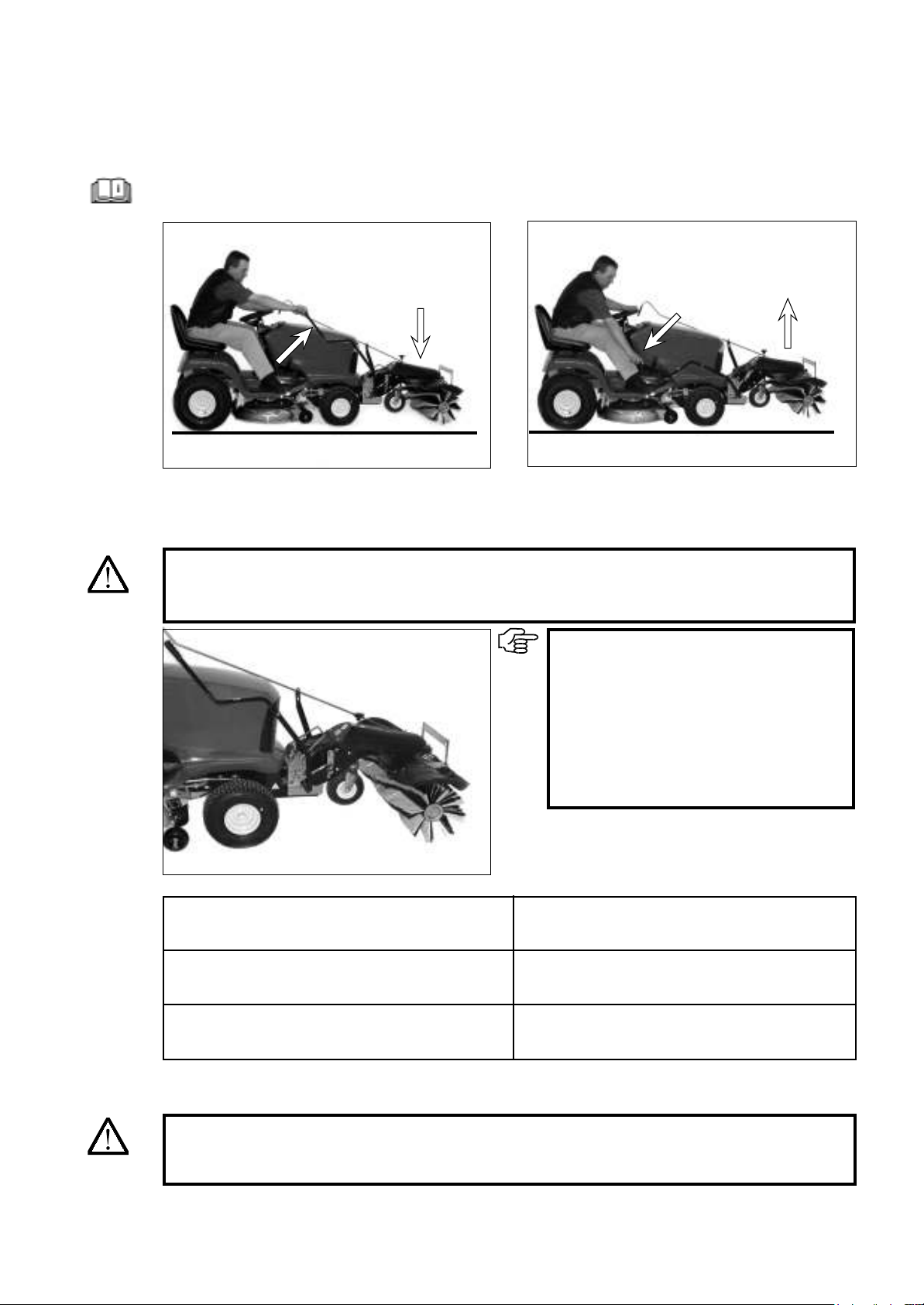
6.8 Switching the brush on and o
Start-up
1) To lower the sweeper, move the liing lever up-
wards. e sweeper switches on.
39
2) To raise the sweeper, push the liing lever down-
wards. e sweeper switches o.
IMPORTANT:
The speed of the sweeper brushes de-
pends on the speed of the engine.
We recommend using as low a sweeper
brush speed as possible in order to mini-
mise dust formation and noise levels.
The driving speed is adjusted using the
selected gear.
WARNING:
Ensure that no persons or property are located in the danger zone, as otherwise this could result
in injury or material damage.
Switch on the engine.
Read the operating instructions provided by the lawn tractor manufacturer.
DANGER!
Once the lawn tractor engine has been started, lowering the sweeper will automatically drive the
sweeper brushes.
Limited debris
Average volume of debris
or sweeping foliage
Large amount of debris or sweeping snow
Low engine speed and
high driving speed
Increased engine speed and
reduced driving speed
Full engine speed and
low driving speed

Maintenance and care
7.1 Basic safety instructions
7 Maintenance and care
IMPORTANT:
Check to ensure that
• No fuel or oil is leaking, and rectify if necessary
• Bolts and nuts are securely fastened, and tighten if necessary
• All moving parts run smoothly, and lubricate if necessary
40
Comply with the adjustment, maintenance and inspec-
WLRQWDVNVDQGLQWHUYDOVVSHFL¿HGLQWKHXVHUPDQXDO
including the information on replacing parts/equip-
ment. These tasks may only be carried out by TXDOL¿HG
personnel. See the maintenance schedule.
Inform operating personnel in advance before carrying
out special work and maintenance work. Nominate a
supervisor.
Switch the machine on and off in accordance with
the user manual and comply with the instructions on
maintenance work for all work that may affect opera-
tion, production adjustment, conversion or adjustment
of the machine and its safety-critical equipment, as
well as work involving inspection, maintenance and
repair. Cordon off a large area for maintenance work
if required.
The machine must be secured against being switched
back on inadvertently if it is completely switched off
for maintenance and repair work:
-Remove the key
$I¿[DZDUQLQJVLJQWRWKHVWDUWHU
Only carry out maintenance and repair work when the
PDFKLQHLVSDUNHGRQDOHYHOVXUIDFHZLWKVXI¿FLHQW
load-bearing capacity and when the machine is secured
against rolling away and overturning.
During replacement, individual parts and larger assem-
blies must be carefully attached and secured to lifting
gear such that they do not pose any risks. Only use
suitable lifting gear in technically perfect condition and
ORDGKDQGOLQJHTXLSPHQW ZLWKVXI¿FLHQWORDGEHDULQJ
capacity. Do not stand or work under suspended loads.
Do not use machine parts as climbing aids.
Keep all handles and steps free from dirt, snow and ice.
Clean oil, fuel or care products from the machine, and
the connections and screw connections in this case in
particular, before starting maintenance/repair work.
Do not use aggressive cleaning agents. Use lint free
cleaning cloths.
Before the machine is cleaned with water, a high-pres-
sure cleaner or other cleaning agents, all openings
which must not allow water/vapour/cleaning agents to
penetrate for reasons of safety or operational function-
ing must be covered over or sealed. Electric motors and
other live components are particularly at risk.
After cleaning, the covers and seals must be completely
removed.
After cleaning, inspect all fuel and oil lines for leaks,
loose connections, areas of abrasion and damage. Im-
PHGLDWHO\UHFWLI\DQ\ GHIHFWVWKDW KD YHEHHQLGHQWL¿HG
Always retighten screw connections that have come
loose during maintenance or repair work.
If safety devices need to be removed during set-up or
maintenance and repair work, they must be reinstalled
and tested immediately after the maintenance and
repair work has been completed.
Ensure that operating and auxiliary materials and
replacement parts are disposed of safely and in an
environmentally friendly manner.
Electrical equipment on a machine must be inspected/
tested on a regular basis. Defects, such as loose connec-
WLRQVDQGEXUQWFDEOHVPXVWEHUHFWL¿HGLPPHGLDWHO\
When working on high-voltage assemblies, connect
the supply cable to earth after the power has been
disconnected and short-circuit the components, e.g.
capacitors, using an earthing rod.
Never allow combustion engines to run in closed or
FRQ¿QHGVSDFHV7KHH[KDXVWJDVHVFRQWDLQSRLVRQRXV
carbon monoxide gas.
Comply with the regulations which apply to the site
of use in question.
2QO\FDUU\RXWZHOGLQJRSHQÀDPHDQGJULQGLQJZRUN
on the machine if this has been expressly approved.
)RUH[DPSOHWKHUHPD\EHDULVNRI¿UHRUH[SORVLRQ
%HIRUH ZHOGLQJ RSHQÀDPH DQG JULQGLQJ ZRUN LV
carried out, remove dust and combustible materials
from the machine and its surrounding area and ensure
WKDWWKHUHLVVXI¿FLHQWYHQWLODWLRQULVNRIH[SORVLRQ
Check all lines, hoses and screw connections regularly
for leaks and signs of external damage. Rectify any
damage immediately. Oil escaping under pressure may
UHVXOWLQLQMXULHVDQG¿UHV
Noise insulation equipment on the machine must be in
the protective position during operation.
Wear the prescribed personal hearing protection.
Observe the safety instructions which apply to the
product when handling oils, greases and other chemical
substances.
Take care when handling hot operating and auxiliary
materials (risk of burning or scalding).
DANGER!
Clean the implement regularly, particularly in the exhaust and engine area. Otherwise, there is an
LQFUHDVHGULVNRI¿UH
Maintenance and care
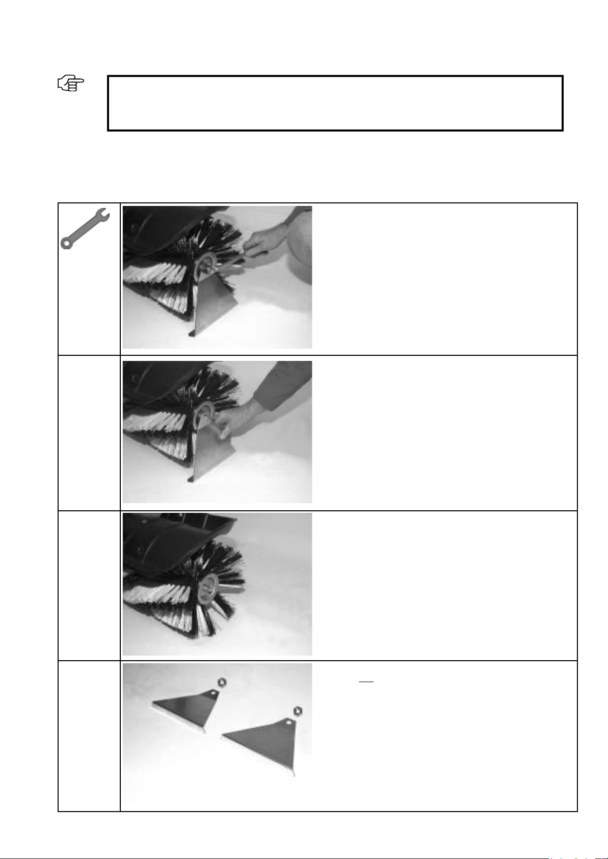
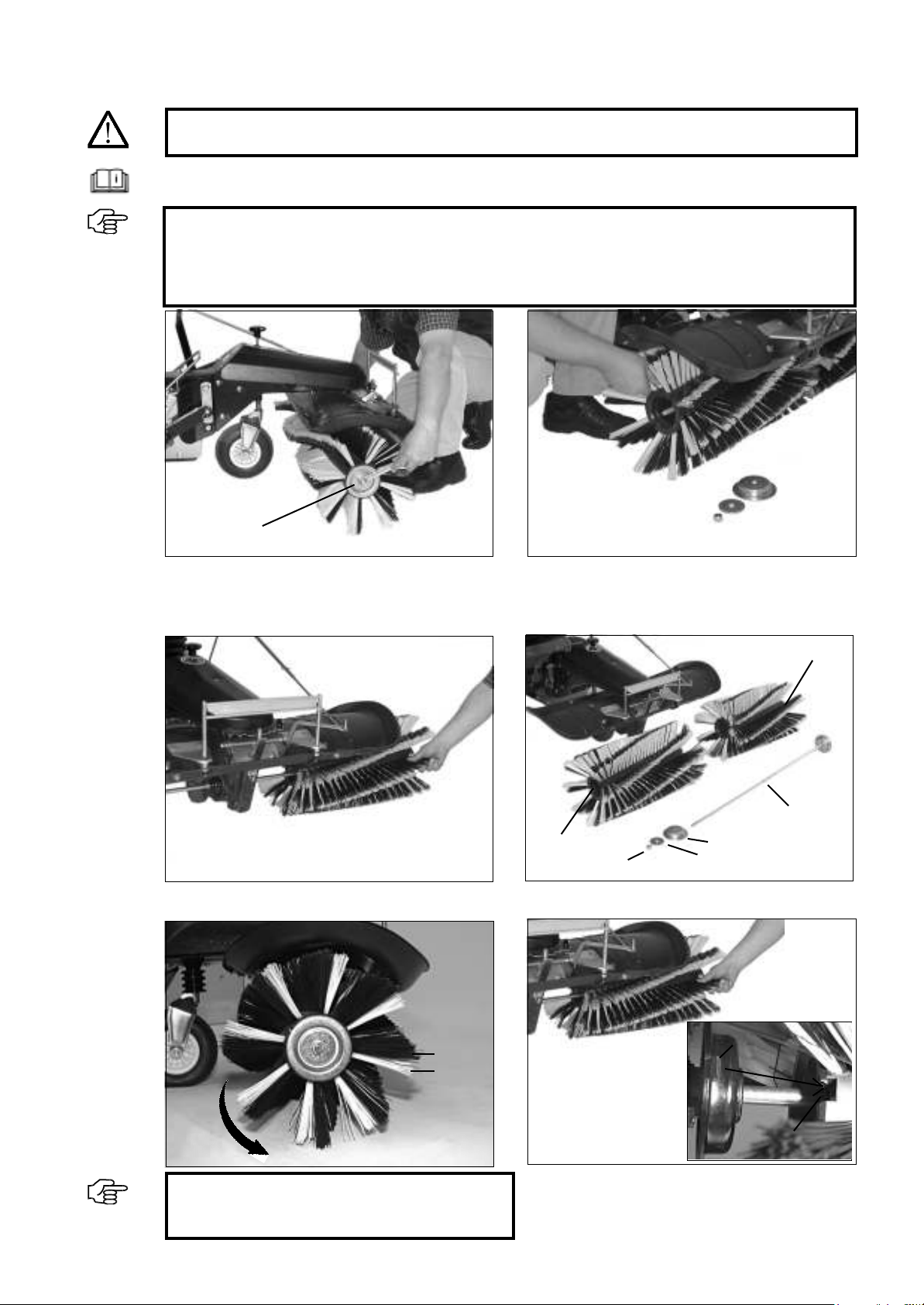
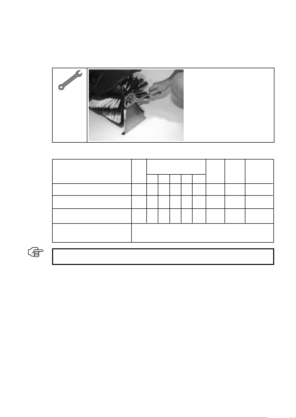
7.2 Replacing the sweeper brushes
IMPORTANT:
The sweeper brushes must be checked at least every 20 operating hours. If your sweeping results
become less than satisfactory or the diameter of the brushes is 220 mm or less, the brushes have to
be replaced. The proper functioning of the sweeper is only guaranteed if original sweeper brushes
with black and white bristles produced by the manufacturer are used.
DANGER!
Switch off the engine. Secure the lawn tractor against being started inadvertently or rolling away.
1) Undo the nut on the le-hand sweeper brush using
a 19 mm combination spanner (hold the nut on
the other sweeper brush still using another 19 mm
combination spanner).
3) Pull out the axle with the second sweeper brush.
2) Now unscrew the nut and remove the brush.
41
Washer
Cap
Lock nut
Right-hand brush
Axle
4) Parts aer disassembly. Replace old brushes with
new ones.
Black
White
IMPORTANT: The black brush row must touch the
ground before the white brush row when moving
in the direction of rotation.
Undo the nut
Le-hand brush
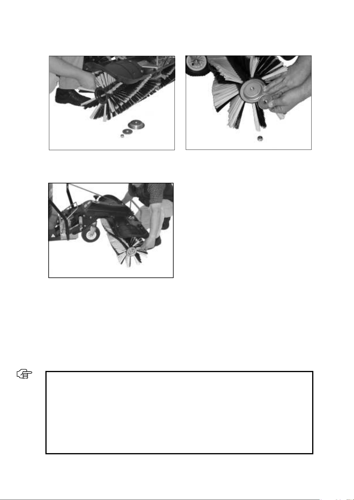
6) When installing the new sweeper brushes, the right-
hand brush is attached to the axle rst. Observe the
above assembly instructions.
Read the operating instructions provided by the lawn tractor manufacturer.
7) Installation information: e recess on the sweeper
brush is placed on the pin on the drive.
Recess
Pin
Maintenance and care
7.3 Cleaning the implement
You should clean the sweeper regularly to keep it in good condition.
Remove loose dirt or dust using a so brush. Wash the plastic surfaces using water and soap. Use commercial
cleaning agents for vehicles. Any cleaning agent residues must be thoroughly rinsed o with clean water. Please
use a plastic care product to make plastic parts shine. Please observe the usage guidelines supplied with the care
product. Glycerine can be used to protect heavily loaded parts against corrosion (e.g. the mounting rods for the
debris container).
IMPORTANT:
Chemical or aggressive cleaning agents must not be used under any circumstances. Doing so will
permanently damage the plastic surfaces and paintwork.
Only use readily biodegradable cleaning agents and care products. This will help to protect the en-
vironment and avoid groundwater pollution.
Cleaning the machine using high-pressure cleaners, steam cleaners and similar devices can per-
manently damage components like ball bearings, seals, engine parts and plastic parts, among oth-
ers. In addition, this can result in water entering the engine. We therefore recommend keeping any
cleaning device hoses a reasonable distance from at-risk components. The water temperature must
not exceed 50 °C.
Please observe any relevant operating instructions for the engine as well.
9) Once both of the brushes have been mounted, push
the washer and the cap onto the axle.
42
8) Push the le-hand sweeper brush onto the axle.
Observe the above assembly instructions.
10) Now secure the sweeper brushes using the lock
nut. (Hold the nut at the other end of the axle still)
Maintenance and care
43
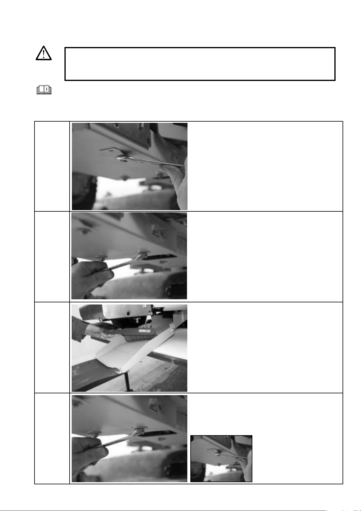
7.4 Additional cleaning instructions
WARNING:
Switch off the engine. Secure the lawn tractor against being started inadvertently or rolling away.
Switch off the engine and remove the spark plug connector before repair, maintenance and cleaning
work.
Read the operating and installation instructions.
Observe the cleaning intervals accordingly.
Clean using a hand-held brush.
Screw back on after cleaning.
Undo the guard.
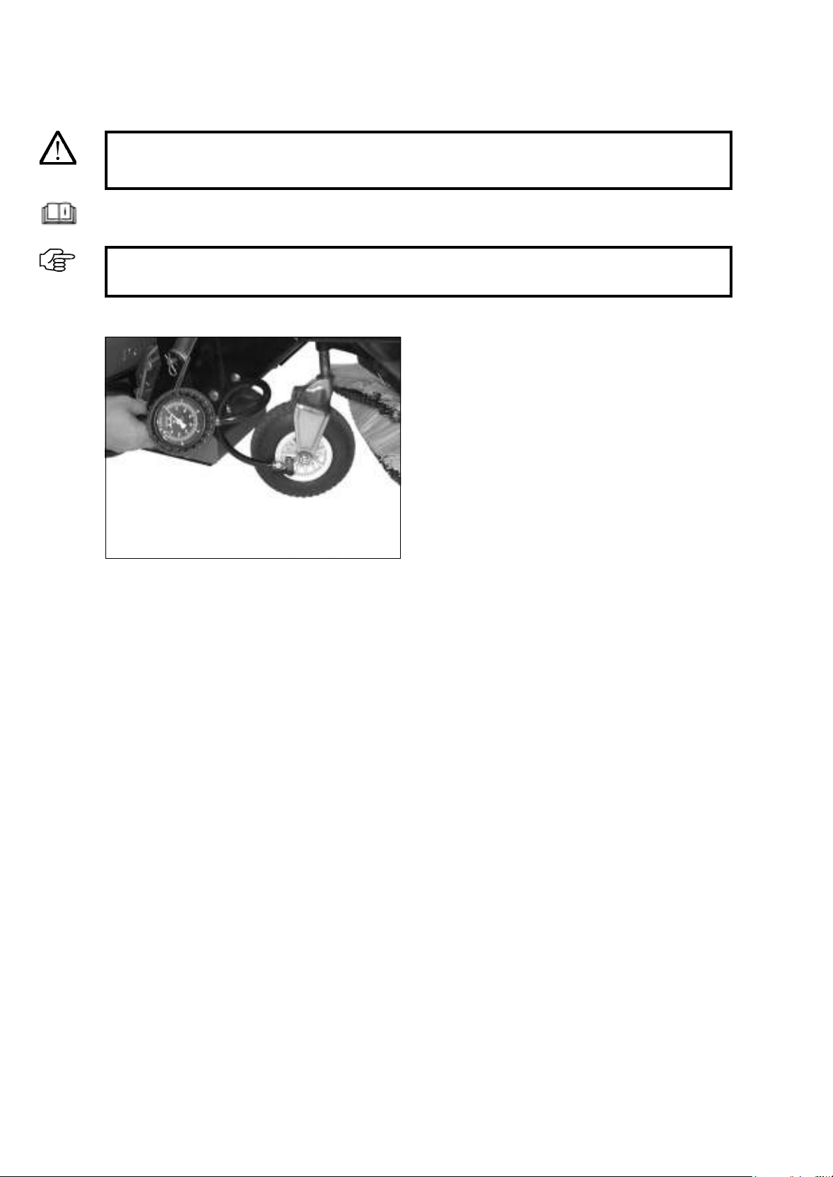
7.5 Checking and correcting the tyre pressure
DANGER!
Switch off the engine. Secure the lawn tractor against being started inadvertently or rolling away.
Comply with the permitted tyre pressure. The tyres will burst at excessive pressures.
Maintenance and care
44
IMPORTANT:
If the tyre pressure is too low, the tube may rub against the rim and become damaged.
Unscrew the valve cap and apply the air tool to check or adjust the pressure. en screw the valve cap back onto
the valve.
Support wheel: 2 bar. If you are working on cobble-
stones, the air pressure can be reduced to 1.5 bar.
Read the operating instructions provided by the lawn tractor manufacturer.
Maintenance and care
7.6 Storage
e sweeper must be properly stored if it will not be required for a longer period of time. If you have additional
questions on this subject, please contact your responsible specialist dealer.
7.7 Maintenance plan
45
Install the supplied supports on the right-
and le-hand sides.
2x SW 19
IMPORTANT:
Observe the maintenance instructions for the lawn tractor.
Check the bolts and nuts
Check the brush roller for wear;
earlier if required
&KHFNWKHDLU¿OWHURQWKHHQJLQHDQGFOHDQ
if required
S = maintenance by a specialist workshop
C = check by the operator
M = maintenance by the operator
Be-
fore
each
use
After the following number
of operating hours:
At least
every
three
months
At least
once
per year
After each
clean
5 10 25 50 100
C
C
C

Transport
8 Transport
46
DANGER!
If the machine is to be transported on a lorry or trailer, loading ramps with a suitable load-bearing ca-
pacity, width and length must be used. The machine must only be loaded with the engine switched off,
without a driver, by being pushed on to the means of transport by an appropriate number of people.
During transport, close the petrol cock (if present), lower the cutting disc, apply the parking brake and
appropriately secure the machine on the means of transport with ropes or chains.
9 Potential faults and how to rectify them
Fault Corrective measureCause
V-belt running not OK
Grinding sounds
Premature V-belt wear
&KHFNWKHFHQWULQJRIWKH9EHOWSXOOH\
the contact surfaces must be clean and
free of burr
Position the V-belt and V-belt tensioner
according to the installation instructions
Reposition the V-belt tensioner according
to the instructions
V-belt pulley installed incorrectly
V-belt does not run over the V-belt
tensioner
The edges of the V-belt and V-belt
idler pulley are in contact
IMPORTANT:
If a fault which is not listed in this table occurs, contact the specialist dealer. Once you have tried all of
the corrective measures described here with no success, contact the specialist dealer.
IMPORTANT:
Only use genuine spare parts from the manufacturer, which you can obtain from your specialist dealer.
This ensures that the implement will work reliably.

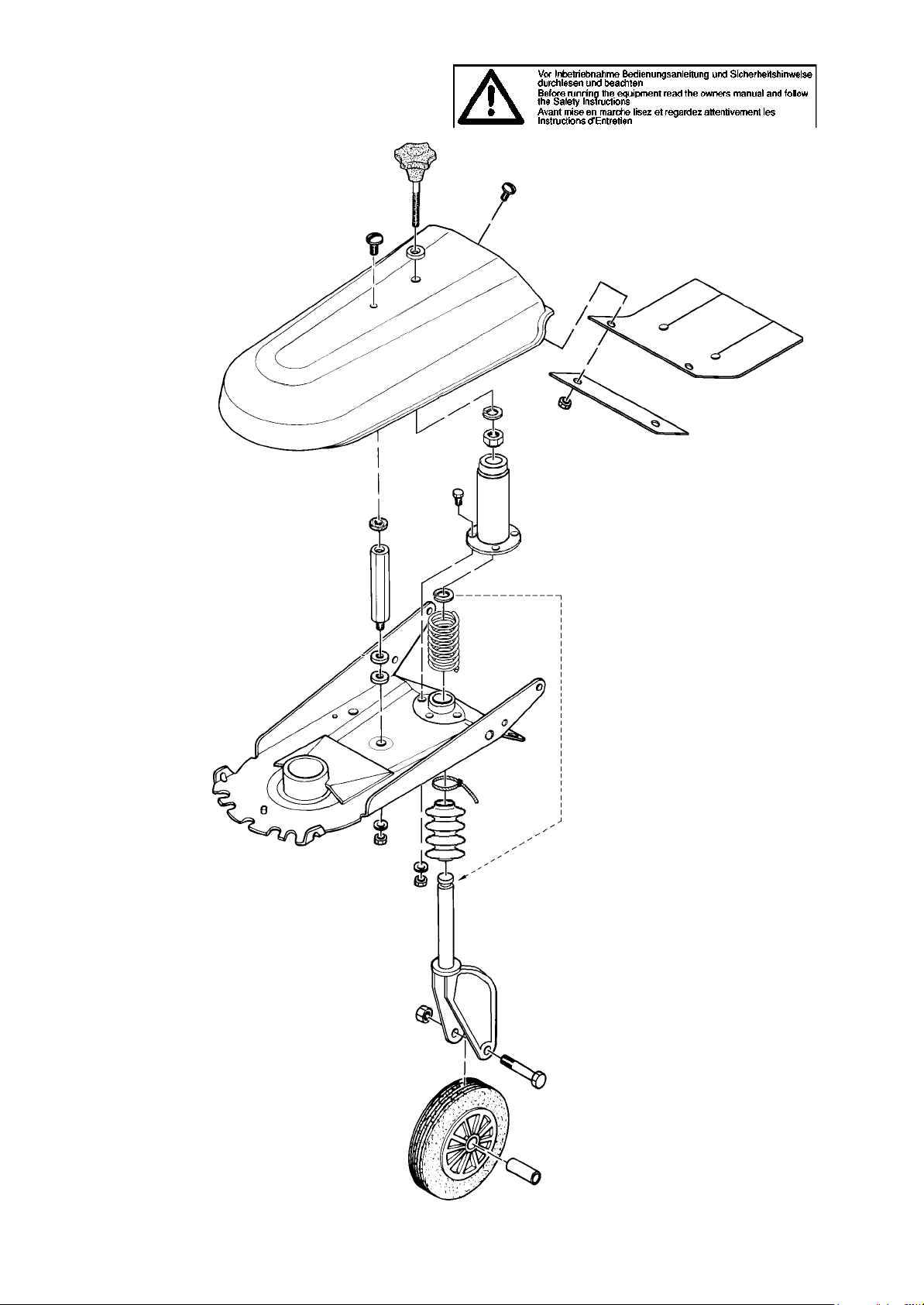
11 Exploded drawings
IMPORTANT:
The "Remarks" column helps you to identify parts.
Only use genuine spare parts from the manufacturer. This ensures that the implement will work reliably.
Item numbers in brackets are wear parts.
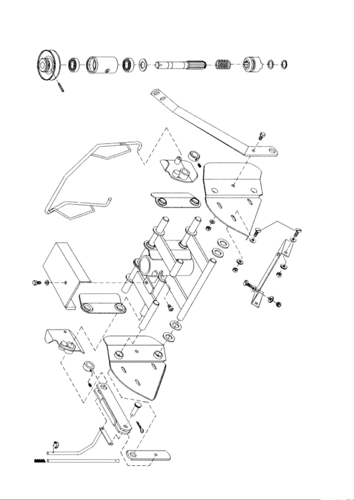
IMPORTANT:
You can identify the parts under "Remarks". Please only use genuine spare parts supplied by the
manufacturer. This is the only way to guarantee the safe operation of the machine.
Troubleshooting and rectifying issues
47
Fault
Sustained grating noise when
the sweeper brush is switched
on
The sweeper brushes are not
turning or stop under load
The sweeper leaves an un-
swept strip in the centre
Poor sweeping results
Poor sweeping results with the
debris container
Snow is pushed back by the
brush
Possible cause
- incorrectly installed belt
- incorrectly installed belt
- defective V-belt
- forward ejection direction
when the sweeper brush is
worn
- worn sweeper brush
- incorrectly installed sweeper
brush
- excessive brush pressure
- not using original brushes
- debris container mounted
incorrectly, sealing lip above
the brush cover
- excessive snow depth
- solid, packed snow
- forward ejection direction,
snow accumulates in front of
the brush
How to rectify the fault
Have V-belt adjusted by a specialist
workshop
Have V-belt replaced by a specialist
workshop
Swivel brush to the right or left; lat-
eral ejection direction
Replace sweeper brush
Install sweeper brush correctly,
check running direction, adjust sup-
port wheel, reduce brush pressure,
use original sweeper brushes with
black and white bristles
Mount debris container correctly
Only usable up to a max. snow
depth of 14 cm
Swivel brush all the way to the right
or left
Swivel brush to the right or left; lat-
eral ejection direction
e terms of the manufacturer's guarantee apply within
the territory of the Federal Republic of Germany.
is guarantee applies to the proper operation of the
implement in accordance with the intended use, pro-
vided that the implement is properly handled and the
information in the operating instructions is complied
with.
is guarantee does not cover damages arising as a
result of normal wear and tear on wear parts such as
10 Terms of the guarantee
lter elements, spark plugs, tyres, bulbs, friction linings,
V-belts and blades, or as a result of improper handling,
negligent use, installation of non-original spare parts,
inadequate care and/or maintenance or failure to com-
ply with the operating instructions.
Outside of the Federal Republic of Germany, the terms
of the guarantee as issued by our responsible national
representative apply.
Exploded drawings
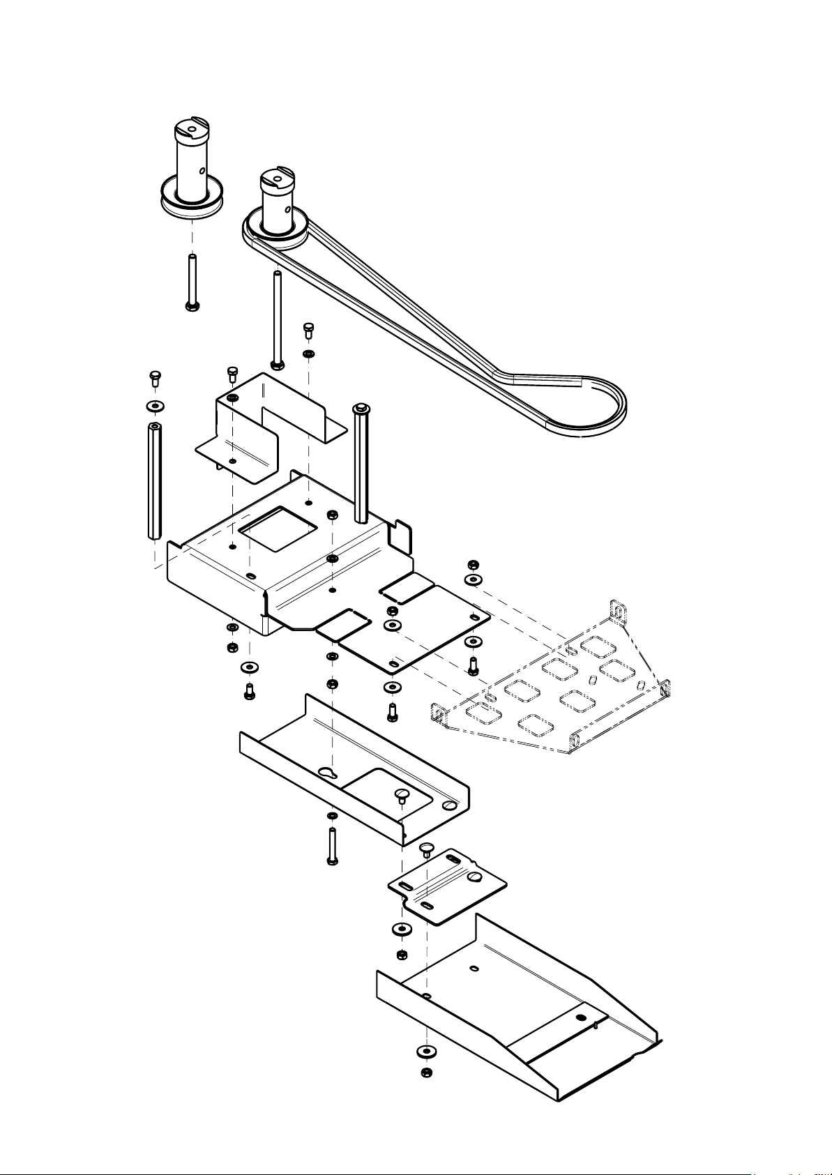
48
12 Drive set – exploded drawing
Exploded drawings
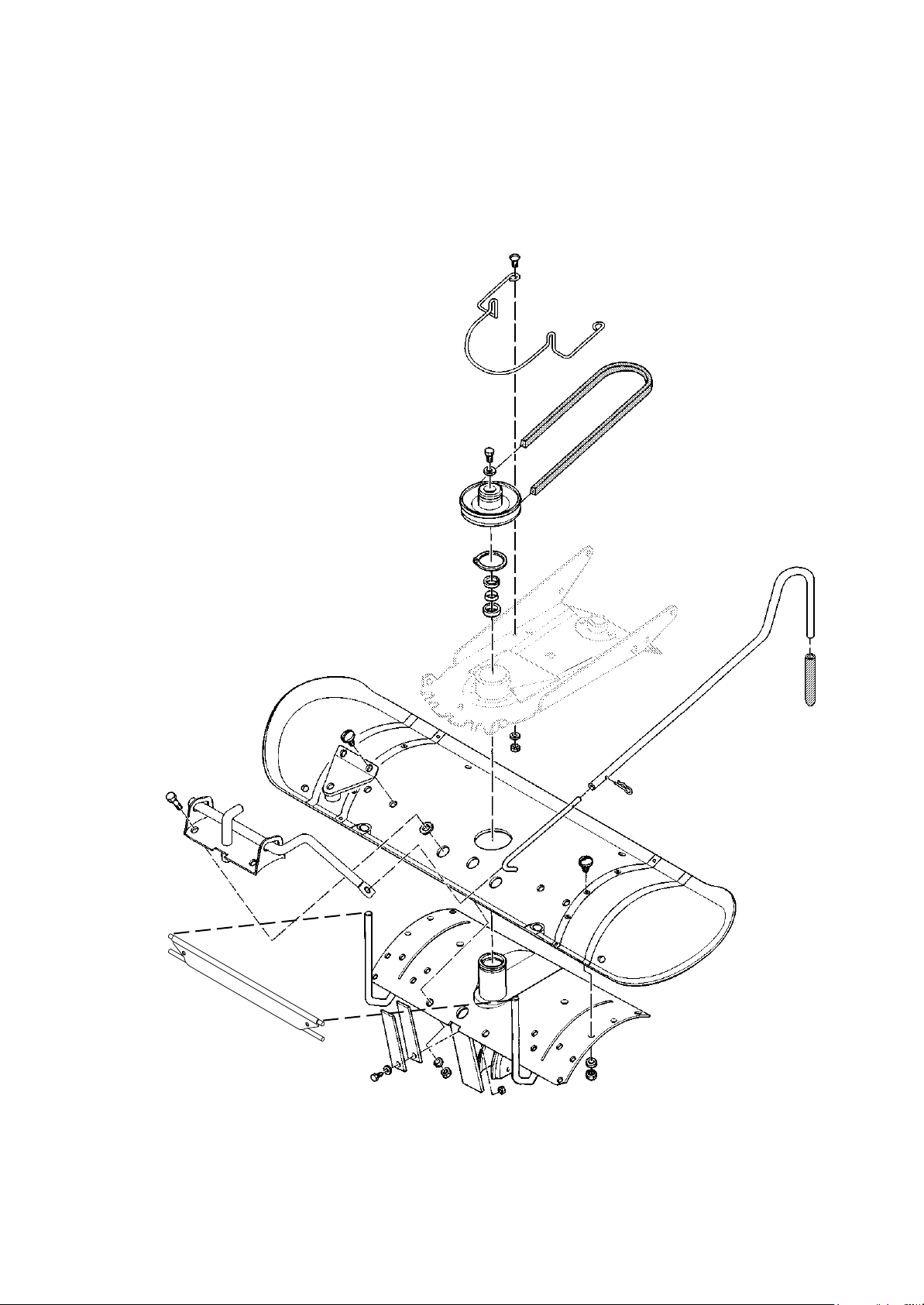
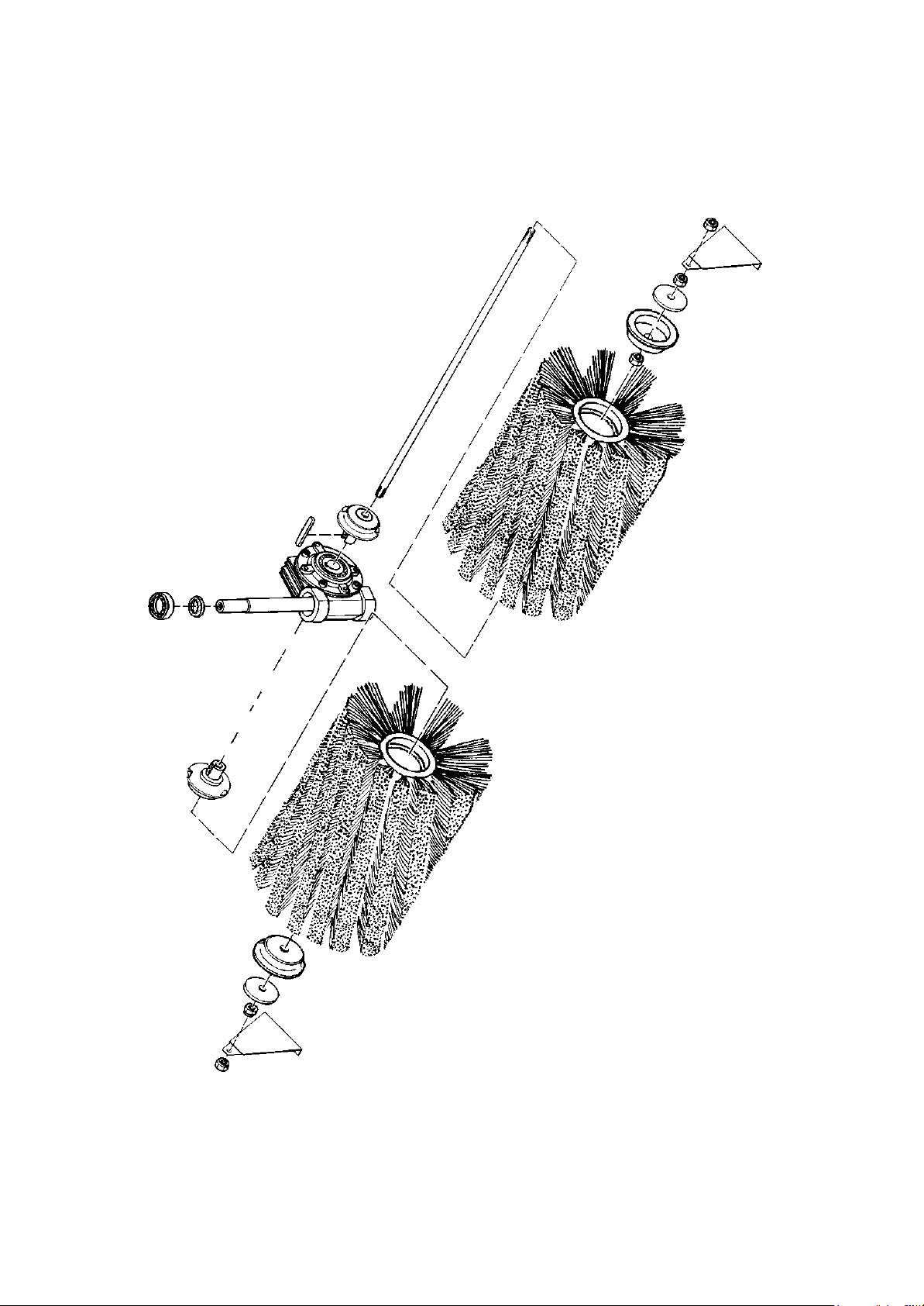
49
13 Sweeper attachment – exploded drawing
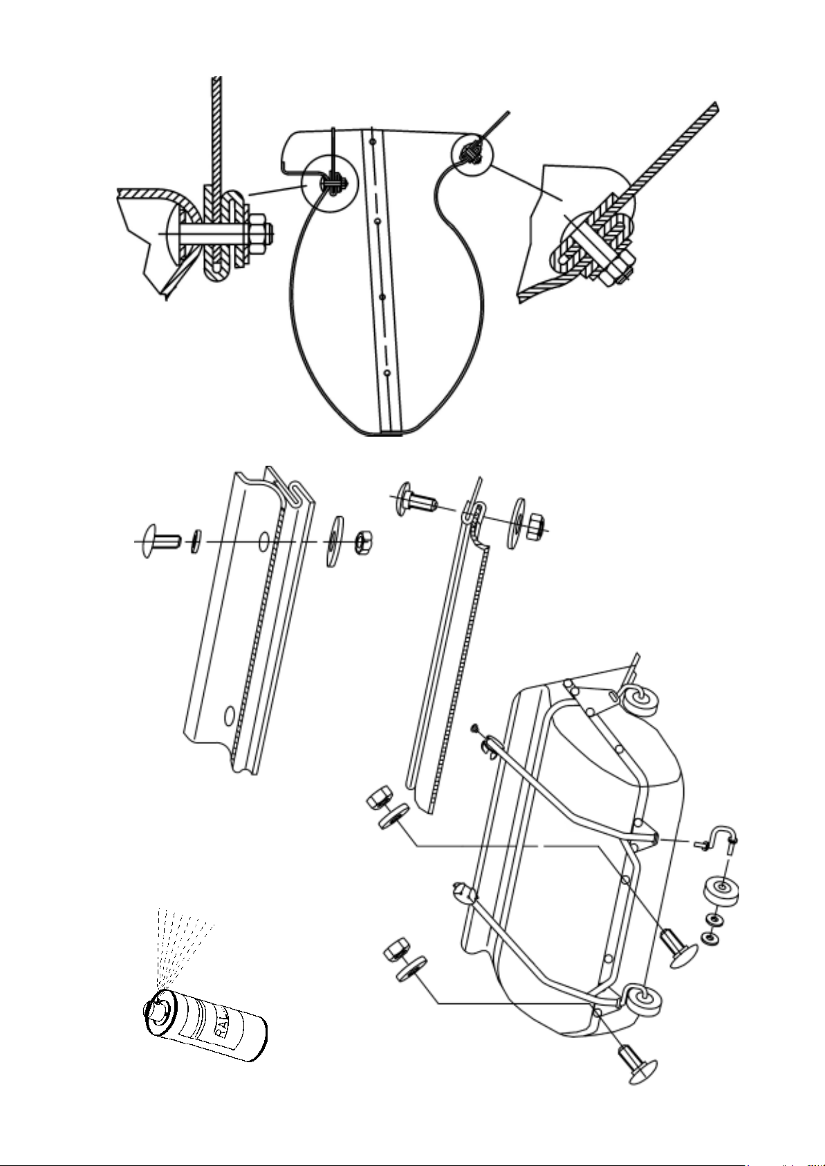
Exploded drawings
50
Exploded drawings
51
Exploded drawings
52
53
Exploded drawings
Top
Bottom

54
14 EC Declaration of Conformity
EC Declaration of Conformity
(in accordance with EC Directive 2006/42/EC)
Manufacturer: Julius Tielbürger GmbH & Co. KG
Maschinenfabrik
Postdamm 12
D-32351 Stemwede-Oppenwehe, Germany
Authorised representative for technical documentation:
Mr Jörg Tielbürger
Julius Tielbürger GmbH & Co. KG
Maschinenfabrik
Postdamm 12
D-32351 Stemwede-Oppenwehe, Germany
We hereby declare that the Tielbürger Sweeper,
Sweeper Type: AD-200-001GI
from Serial no.: 4526817
the device described in this manual, in combination with the Tielbürger system
AN-156-001GI which corresponds to interchangeable equipment in according to the EC
Machinery Directive 2006/42/EC.
The device may only be used in accordance with this operating instructions.
$Q\XVHRIWKHPDFKLQHQRWVSHFL¿HGRQWKHVHRSHUDWLQJLQVWUXFWLRQVLVQRWSHUPLWWHG
The components to be used with this device are listed in the declaration of conformity
for the associated Tielbürger attachment system
Stemwede, 12.10.16
Julius Tielbürger
GmbH & Co.KG
….................................
L. Tielbürger
(Managing Director)