Loading ...
Loading ...
Loading ...
8. ASSEMBLY
- 7 -- 10 -
6. TECHNICAL DESCRIPTION
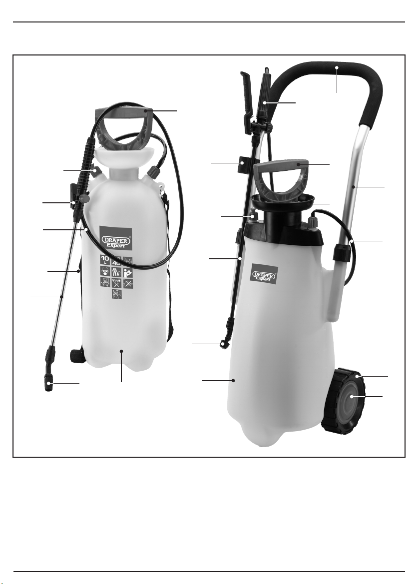
6.1 IDENTIFICATION
Pump handle.
Safety valve.
Wheel.*
Wheel cover.*
Spray bottle.
Nozzle.
Lance.
Fill inlet.
Trigger assembly.
Hose.
Foam handle grip.*
Handle.*
Lance holder.*
Carry strap.
Ɨ
FIG.5
FIG.6
FIG.7
FIG.8
8.2 HANDLE ASSEMBLY
(82583 only) – FIGS. 5 – 8
– Slide the 2 handle fixings over the
handle section .
– Slide the 2 shafts of the handle over
the handle mounting sections moulded into
the spray bottle .
– Turn the 2 handle fixings clockwise to
secure the handle in place .
– Position the lance holder onto the
handle , locating it with the hole in the
shaft.
– Press fit the lance holder into place on the
shaft.
*Applicable to Stock No.82583 only.
Ɨ
Applicable to Stock No.82460 only.
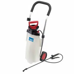
Stock No.82583
Stock No.82460
Loading ...
Loading ...
Loading ...