Loading ...
Loading ...
Loading ...
Page 25 of 64
TABLE 1 THERMOSTAT WIRE INFORMATION
WIRE SIZE
MAX. WIRE LENGTH
AWG
mm
ft.
m
22
0.6
10
3.0
20
0.8
25
7.6
18
1.0
40
12.2
16
1.3
64
19.5
14
1.6
100
30.5
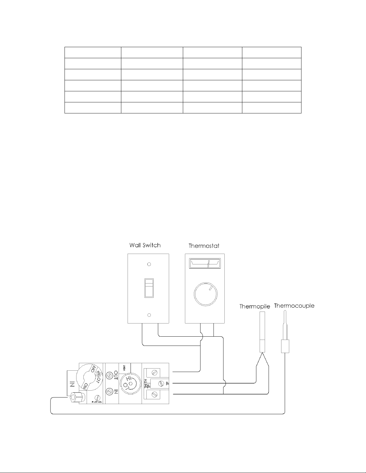
2) After the unit is installed and the gas line hooked up, crimp a fork connector to each wire and
attach them to the TH/TP and TH screws located on the valve.
Après que l'unité est installée et la conduite de gaz accroché, sertir un connecteur fourchette pour
chaque fil et les joindre à la vis TH / TP et TH situé sur la valve.
3) Check tests can be performed on the valve by using the trouble-shooting guide, Section 5.0.
Vérifiez les tests peuvent être effectués sur la valve en utilisant le guide de dépannage, la
section 5.0.
4) This switch may be connected in parallel with a thermostat, digital on/off remote or wall switch
(see Figure 4).
Ce commutateur peut être connecté en parallèle avec un thermostat numérique, télécommande
marche / arrêt ou un interrupteur mural (voir Figure 4).
Figure 4
Loading ...
Loading ...
Loading ...