USER’S MANUAL
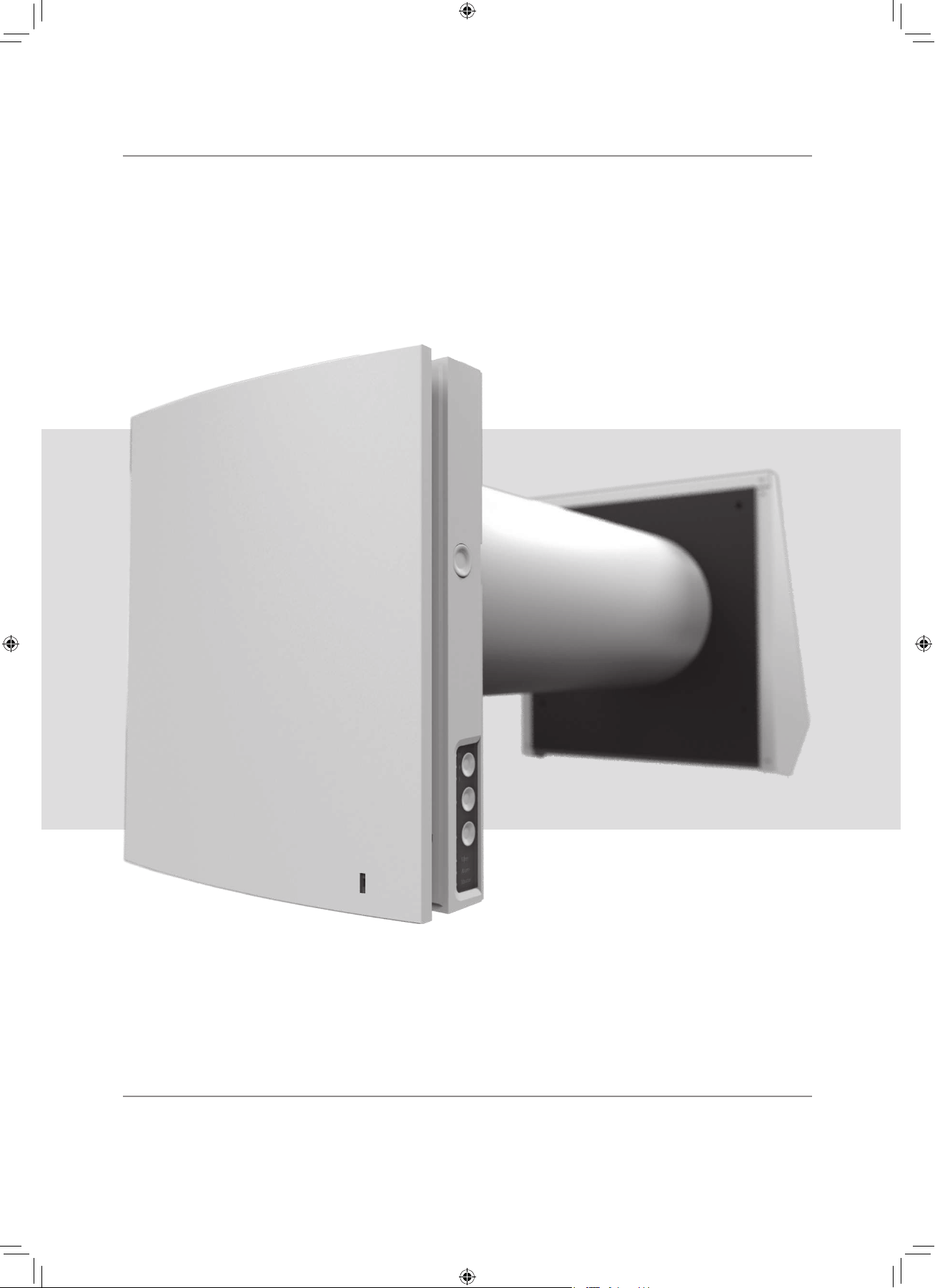
Single-room reversible
energy regeneration ventilator
TwinFresh Expert
F112EN-02.indd 1 05.10.2015 16:09:51
2
Read the user’s manual carefully prior to installing and operating the unit.
Fulfil the user’s manual requirements as well as the provisions of all the applicable local and national construction, electrical and
technical norms and standards.
The warnings contained in the user’s manual must be considered most seriously since they contain vital personal safety information.
Failure to follow the rules and safety precautions noted in this user’s manual may result in an injury or unit damage.
After a careful reading of the manual, keep it for the entire service life of the unit.
While transferring the unit control the User’s manual must be turned over to the receiving operator.
Symbol legend:
WARNING!
DO NOT!
The user’s manual consisting of the technical details, operating
instructions and technical specification applies to the installation
and mounting of the single-room energy regeneration reversible
ventilator TwinFresh Expert, (hereinafter « the unit» as mentioned
in the «Safety Requirements» and «Manufacturer’s Warranty»
sections as well as in warnings and information blocks).
Safety requirements 2
Purpose 4
Delivery set 4
Designation key 4
Main technical parameters 5
Design and operating logic 6
Mounting and set-up 8
Unit connection and control 11
Maintenance 15
Troubleshooting 17
Storage and transportation regulations 17
Manufacturer's warranty 18
Acceptance certificate 19
Seller information 19
Installation certificate 19
Warranty card 20
CONTENT
SAFETY REQUIREMENTS
UNIT MOUNTING AND OPERATION SAFETY PRECAUTIONS
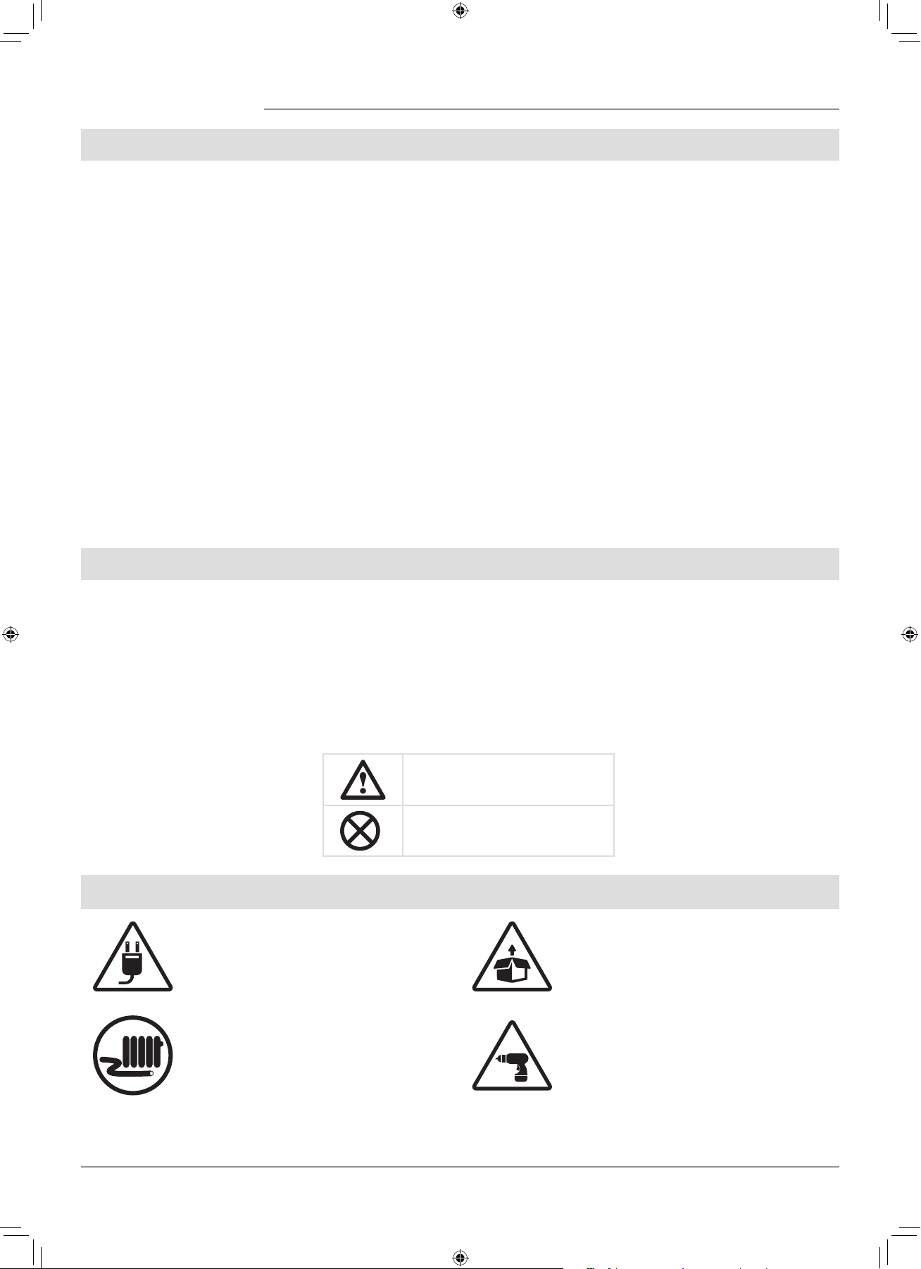
• Disconnect the unit from power mains
prior to any installation operations.
• Unpack the unit with care.
• Do not lay the power cable of the unit in
close proximity to heating equipment.
• While installing the unit follow the
safety regulations specific to the use of
electric tools.
F112EN-02.indd 2 05.10.2015 16:09:52
3
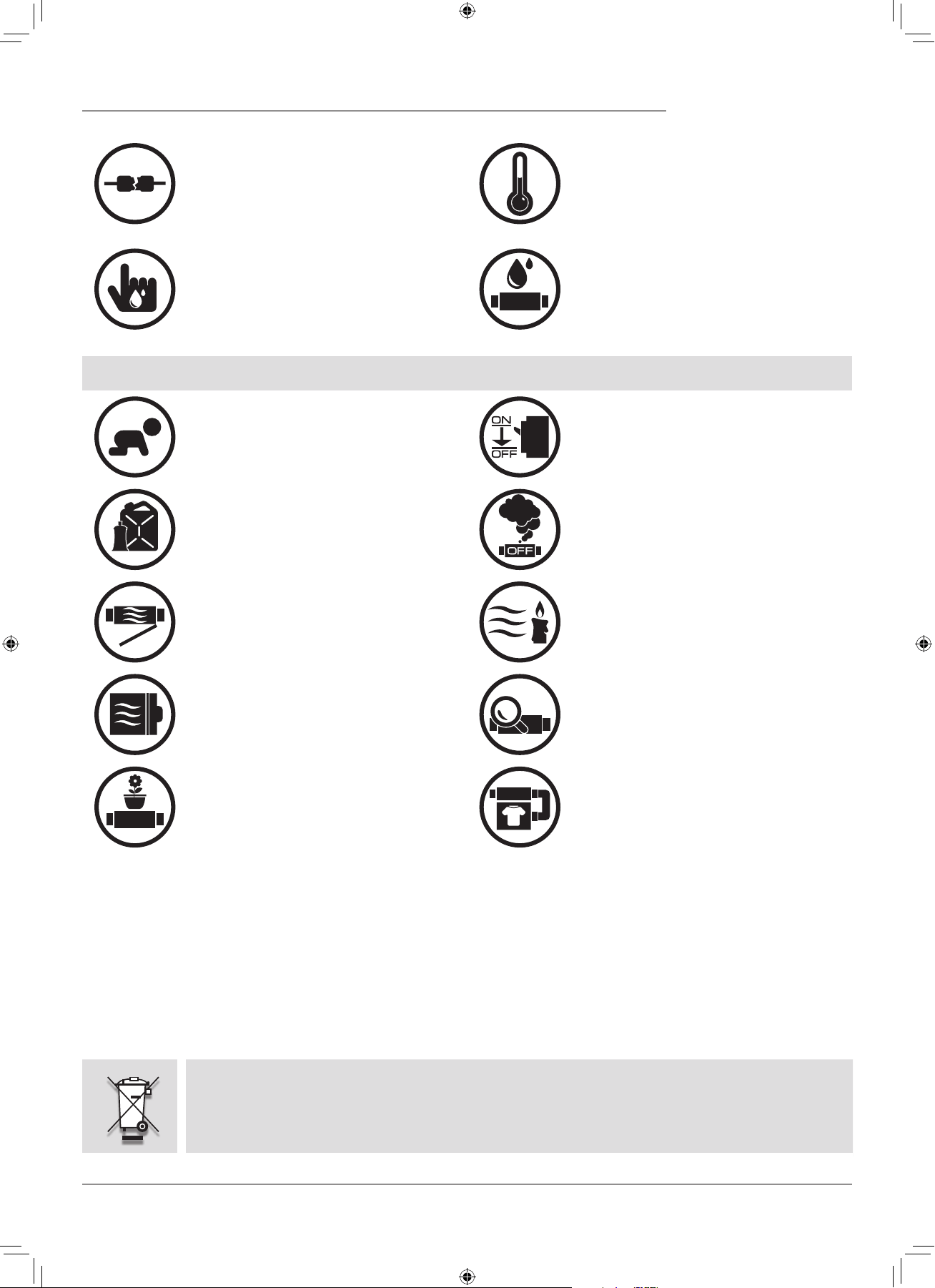
• Do not use damaged equipment or cables
when connecting the unit to power mains.
• Do not operate the unit outside the
temperature range stated in the user’s
manual.
• Do not operate the unit in aggressive or
explosive environments.
• Do not touch the unit controls with wet
hands.
• Do not carry out the installation and
maintenance operations with wet hands.
• Do not wash the unit with water.
• Protect the electric parts of the unit
against ingress of water.
UNIT MOUNTING AND OPERATION SAFETY PRECAUTIONS
• Do not allow children to operate the unit.
• Disconnect the unit from power mains prior
to any technical maintenance.
• Do not store any explosive or highly
flammable substances in close proximity to
the unit.
• When the unit generates unusual sounds,
odour or emits smoke disconnect it from
power supply and contact the Seller.
• Do not open the unit during operation.
• Do not direct the air flow produced by the
unit towards open flame or ignition sources.
• Do not block the air duct when the unit is
switched on.
• In case of continuous operation of the unit
periodically check the security of mounting.
• Do not sit on the unit and avoid placing
foreign objects on it.
• Use the unit only for its intended purpose.
RECYCLE AT THE END OF THE SERVICE LIFE.
DO NOT DISPOSE THE PRODUCT WITH UNSORTED MUNICIPAL TRASH.
F112EN-02.indd 3 05.10.2015 16:09:55
4
The unit is designed to ensure continuous mechanical air exchange in houses, offices, hotels, cafes, conference halls and other
utility and public spaces as well as to recover the heat energy contained in the air extracted from the premises to warm up the filtered
stream of supply air.
The ventilator is equipped with a ceramic regenerator that enables supply of fresh filtered air heated by means of extract air heat
energy regeneration.
The ventilator is designed for through-the-wall mounting.
PURPOSE
DELIVERY SET
DESIGNATION KEY
The unit is rated for continuous operation.
Transported air must not contain any flammable or explosive mixtures, evaporation of chemicals, sticky substances, fibrous
materials, coarse dust, soot and oil particles or environments favourable for the formation of hazardous substances (toxic substances,
dust, pathogenic germs).
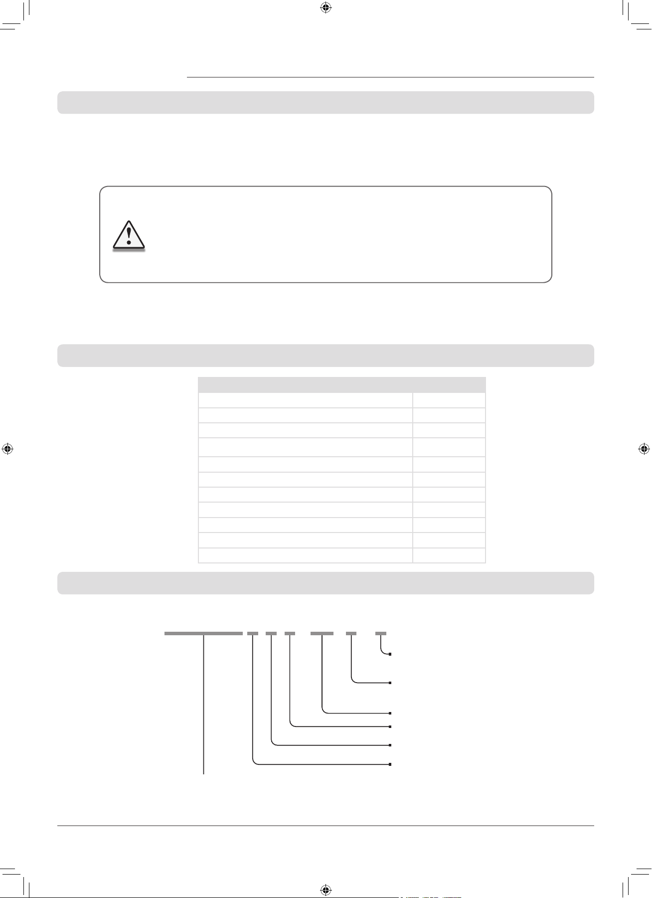
Name Quantity
Indoor assembly unit of the ventilator 1 item
Air duct 1 item
Sound-absorbing layer 1 item
Cartridge assembly 1 item
Outer ventilation hood 1 item
Remote control 1 item
Cardboard mounting plate 1 item
Mounting kit 2 sets
User's manual for the ventilator 1 item
Installation instruction for the ventilation hood 1 item
Packing box 1 item
TwinFresh Expert R A 1 - 50 L - 2
Ventilation hood model
_ — EH white 160—
2 — EH-2 white 160
Air duct length
_ — 500 mm
L —700 mm
Rated air capacity [m
3
/h]
Front panel modification
1 - flat front panel
Controls availability
A —controls and control unit are included in the delivery set
Air duct cross section
R — round
THE UNIT MAY NOT BE OPERATED BY CHILDREN OR PERSONS WITH REDUCED
PHYSICAL, MENTAL OR SENSORY CAPACITIES, OR LACKING THE APPROPRIATE TRAINING.
THE UNIT MUST BE INSTALLED AND CONNECTED ONLY BY PROPERLY QUALIFIED
PERSONNEL AFTER THE APPROPRIATE BRIEFING.
THE CHOICE OF UNIT INSTALLATION LOCATION MUST PREVENT UNAUTHORIZED
ACCESS BY UNATTENDED CHILDREN.
F112EN-02.indd 4 05.10.2015 16:09:55
5
TECHNICAL DATA
The ventilator is rated for indoor application with the ambient temperature ranging from -30C (-22 F) up to +50C (+122 F)
and relative humidity up to 97%.
The ventilator is rated as a class II electric appliance.
Ingress Protection (IP) rating from solid objects and liquids IP 24.
The ventilator design is regularly improved, so some models may slightly differ from those ones described in this manual.
The supplied ventilation hood model depends on the ventilator model.
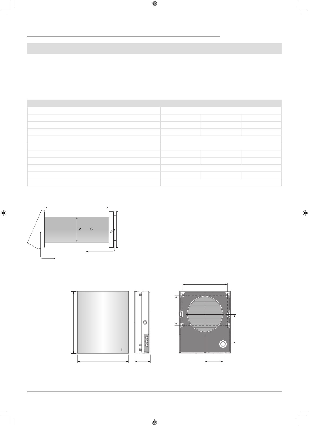
The overall dimensions of the outer ventilation hood are stated in the
installation instruction.
The overall dimensions of the front panel are stated below.
235
(9 ¼")
71
(2 ⁄")
137
(5 ⁄")
85
(3 ⁄")
207
(8 ⁄")
138
(5 ⁄")
285
(11 ¼")
160 ( 6 5⁄16")
Air duct length
Outer ventilation hood
Front panel
OVERALL DIMENSIONS OF THE INDOOR ASSEMBLY UNIT, MM (INCH)
TECHNICAL DATA
Speed I II III
Supply Voltage, 50-60 Hz [W] 1~100-240
Power consumption [W]
3.61 4.15 5.2
Total current consumption [A]
0.025 0.030 0.039
Air capacity [m3/h] (CFM)
15 (9) 30 (19) 50 (29)
Filters
G3 (MERV 7); F7 (MERV 13) Optional
Max. transported medium temperature [
0
C (
0
F)]
from -30 (-22) up to 50 (122)
Noise level, 1 m [dB(A)] (Sones)
20 (0,6) 27 (1,0) 30 (1,2)
Noise level, 3 m [dB(A)] (Sones)
11 (0,3) 18 (0,5) 21 (0,6)
Noise level attenuation [dB(A)] (Sones)
42 (2,5)
Heat recovery efficiency [%]
97 90 82
Ingress Protection
IP 24
F112EN-02.indd 5 05.10.2015 16:09:56
6
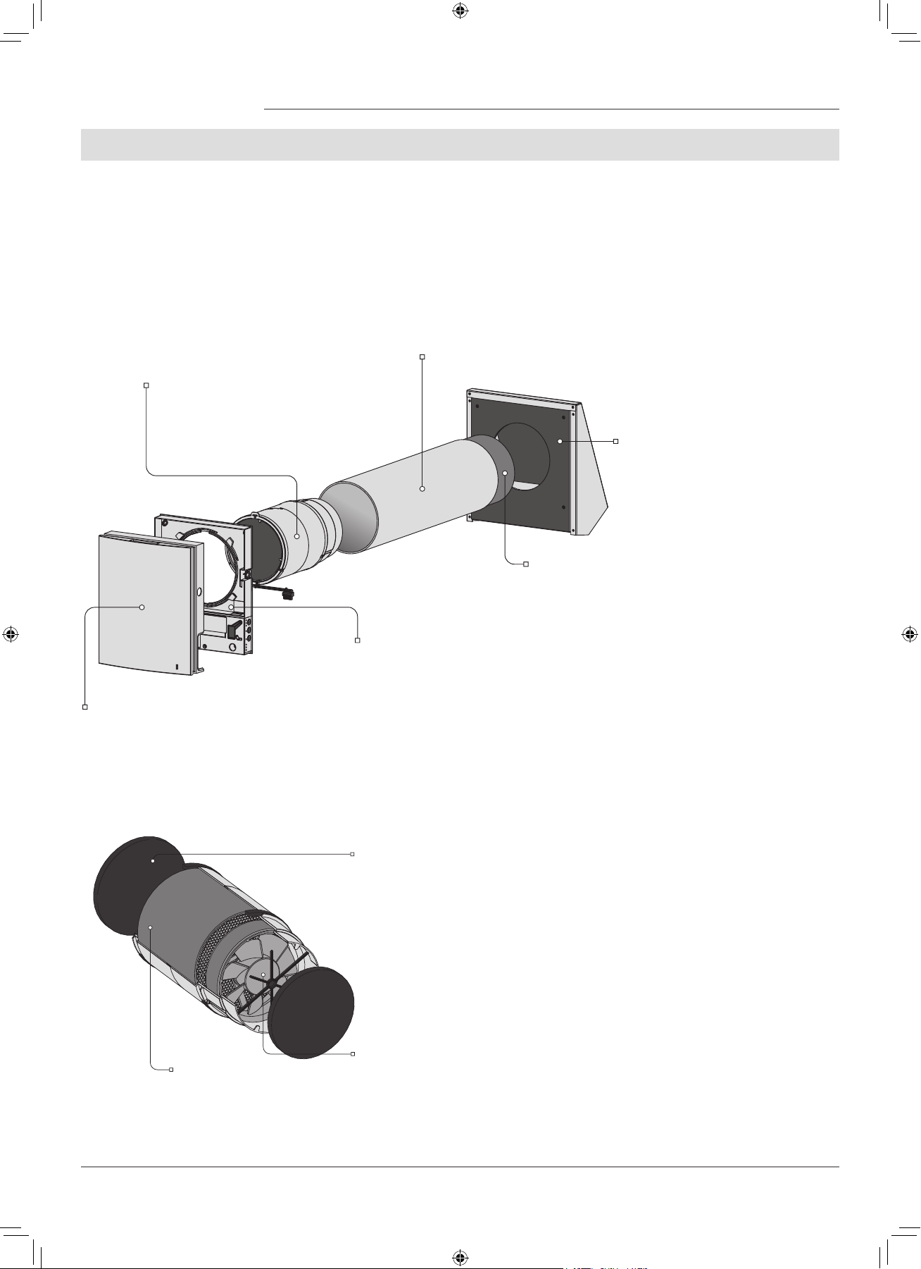
Front part of the indoor assembly unit
Performs decorative function.
The design enables cut-out of the air duct
in case of a long-lasting standstill of the
ventilator.
Back part of the indoor assembly unit
The assembly unit includes a circuit board
and basic control units located on the side
of the indoor assembly unit.
Cartridge
An assembly unit consists of the fan, regen-
erator and the filters.
Generates air flow, provides energy regen-
eration and air cleaning.
Air duct
A plastic air duct.
Sound-absorbing layer
A layer of sound-absorbing material for
attenuation of noise generated during the
ventilator operation.
Outer ventilation hood
Protect the ventilator from ingress of
water and foreign objects.
Each ventilator model has a matching
ventilation hood model.
Filter
Cleans the air flowing through
the ventilator of dust and for-
eign objects.
Prevents contamination of the
energy regenerator.
Fan
Generates air flow.
Regenerator
Provides extract air energy re-
generation for warming up of
supply air flow.
DESIGN AND OPERATING LOGIC
The ventilator consists of an indoor assembly unit with a decorative front panel, a cartridge, an air duct, a sound absorbing material
and an outer ventilation hood.
Cartridge is the basic functioning part of the ventilator.
The cartridge consists of the fan, the regenerator and two filters that ensure rough air filtration and prevent ingress of dust and
foreign objects into the regenerator and the fan.
The indoor assembly unit is equipped with automatic shutters that close during the ventilator standstill and prevent air backdraft.
The ventilation hood on the outer side prevents ingress of water and foreign objects into the ventilator.
Cartridge is a solid block consisting of the
fan, regenerator an the filters.
The filters are easy removable for technical
maintenance.
VENTILATOR DESIGN
CARTRIDGE DESIGN
F112EN-02.indd 6 05.10.2015 16:09:56
7
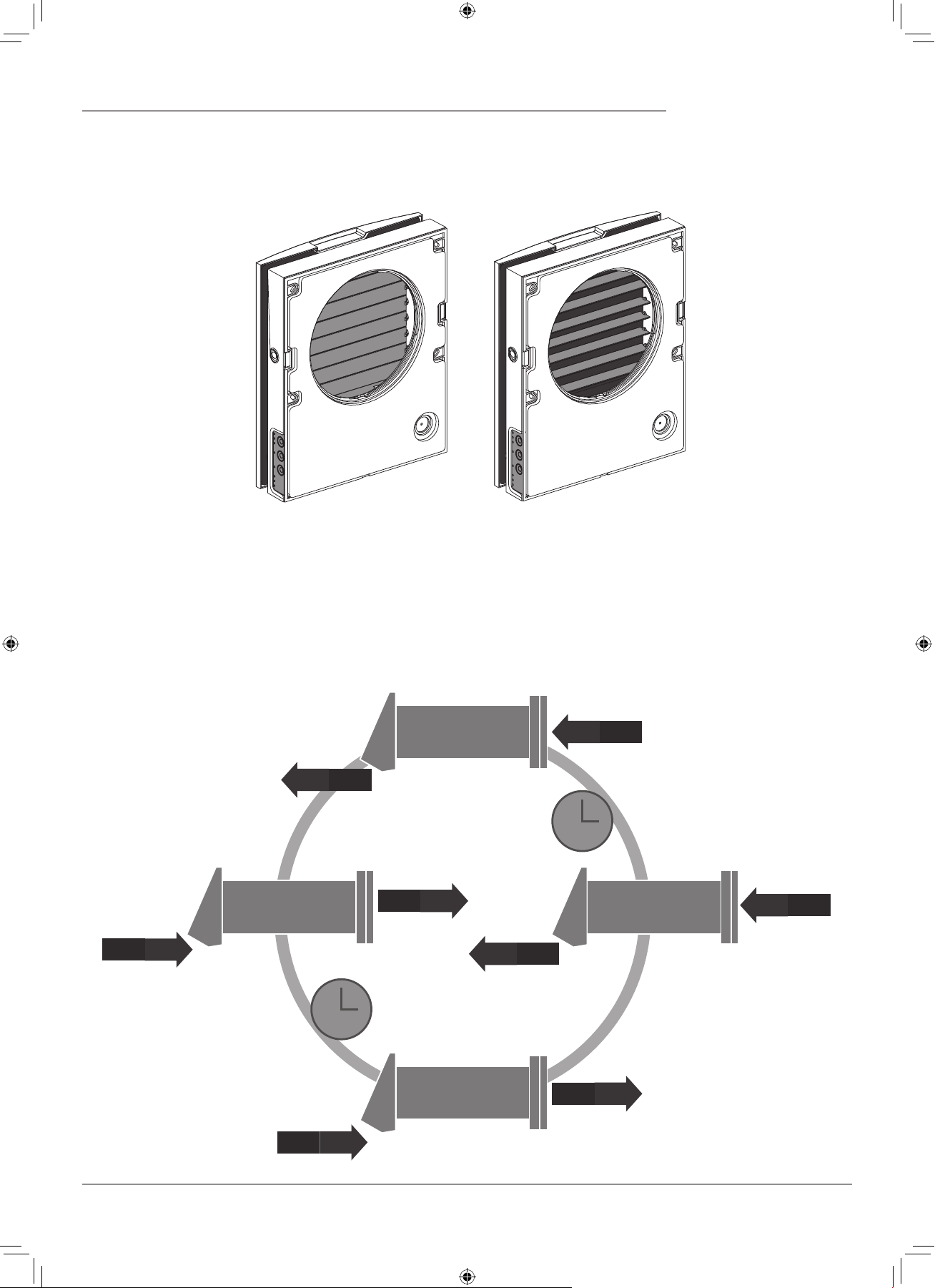
Shutters closed Shutters opened
The indoor assembly unit is equipped with automatic shutters. During the ventilator standby the automatic shutters open and let free
air flow through the ventilator. The automatic shutters close 2 minutes after shutdown of the ventilator.
OPERATING LOGIC OF THE AUTOMATIC SHUTTERS
VENTILATOR OPERATION MODES
The ventilator has two ventilation modes:
Ventilation. The ventilator operates either in extract or supply mode at set speed.
Regeneration. The ventilator operates in reversible mode with heat and humidity regeneration
.
A
I
R
E
X
T
R
A
C
T
A
I
R
S
U
P
P
L
Y
+20˚C
-7˚C
+20˚C
-7˚C
+17˚C
-10˚C
+17˚C
-10˚C
70 sec.
19.4˚F
19.4˚F
14˚F
14˚F
62.6˚F
62.6˚F
68˚F
68˚F
70 sec.
In Regeneration mode the ventilator operates in two cycles, 70 seconds each.
Cycle I.
Warm stale air is extracted from the room. As it flows through the regenerator, it heats and moisturizes the regenerator, transferring
up to 97% heat energy. In 70 seconds as the ceramic regenerator gets warmed the ventilator is switched to supply mode.
Cycle II.
Fresh intake air from outside flows through the ceramic regenerator and absorbs accumulated moisture and heat up to the room
temperature. In 70 seconds as the ceramic regenerator gets cooled down, the ventilator is switched into extract mode and the cycle is
renewed.
F112EN-02.indd 7 05.10.2015 16:09:57
8
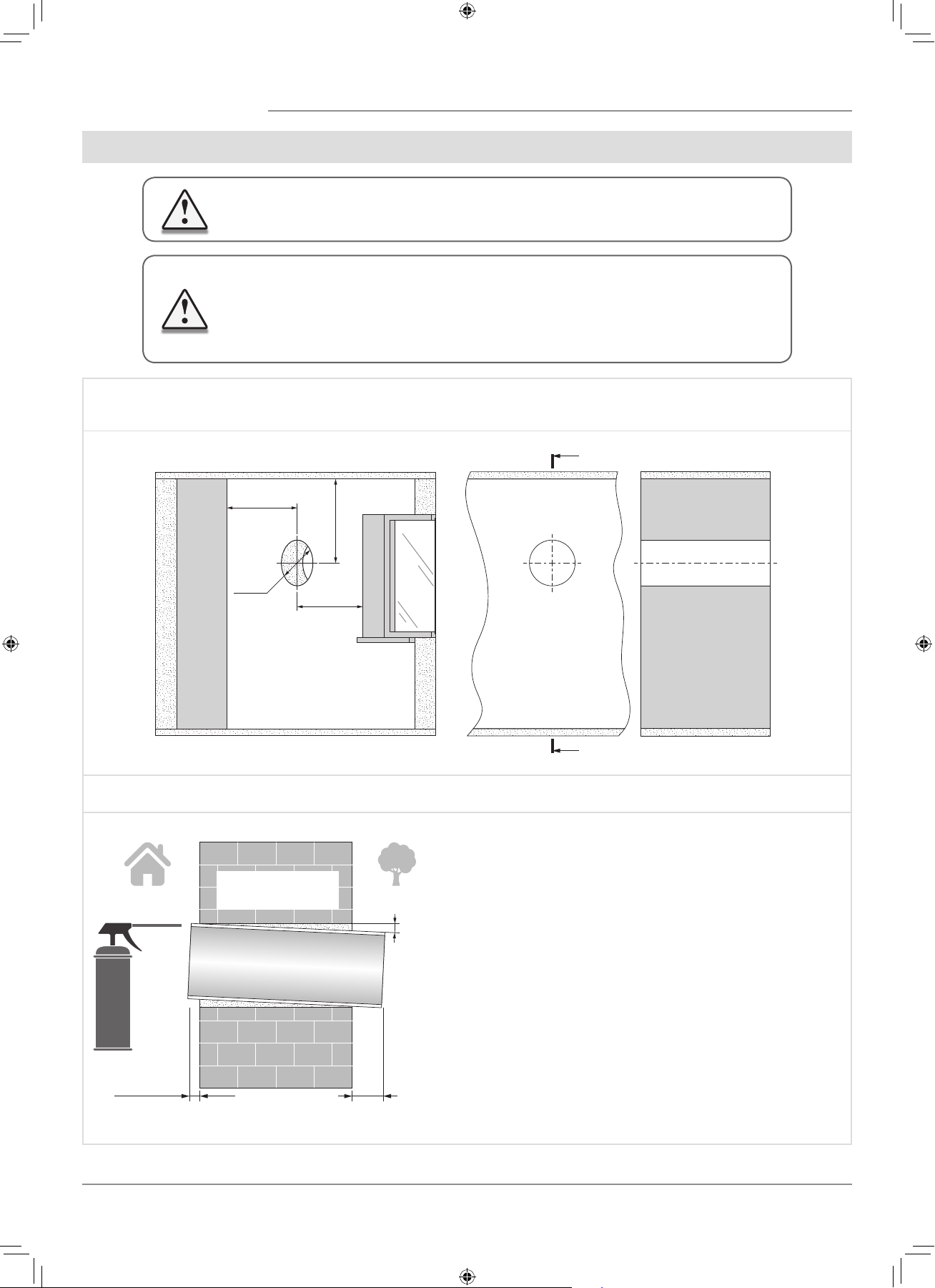
MOUNTING AND SET-UP
1. Prepare a round thorough hole in the outer wall.
The hole size in the wall is shown in the figure below.
While preparing a core hole it is recommended to make preparations for layout of the power cable and other required cables.
Ø 180
Ø 7 ⁄"
min 500
min 19 ⁄"
min 500
min 19 ⁄
min 500
min 19 ⁄"
A
A
A-A
2. Insert the air duct in the wall and fix it with mounting foam. The telescopic air duct end must protrude for the distance that enables
installation of the outer ventilation hood. For details, refer to the installation instruction for the ventilation hood.
0 - 3 mm
(0 - 1⁄8")
A
Fill the gaps between the wall
and the telescopic air duct
with a mounting foam.
min 3°
Install the air duct in the wall in such a way so it protrudes from
the wall surface for maximum 3 mm or is flush with the wall.
Install the air duct with the minimum slope 3˚ downwards.
On the outer wall side the air duct end must protrude to a
distance that enables installation of the outer ventilation hood.
Distance A is stated in the installation instruction for the
ventilation hood.
READ THE USER’S MANUAL PRIOR TO MOUNTING THE VENTILATOR.
ATTENTION!
DO NOT BLOCK THE AIR DUCT OF THE INSTALLED VENTILATOR WITH DUST
ACCUMULATING MATERIALS, SUCH AS CURTAINS, CLOTH SHUTTERS, ETC. AS IT
PREVENTS AIR CIRCULATION IN THE ROOM.
F112EN-02.indd 8 05.10.2015 16:09:57
9
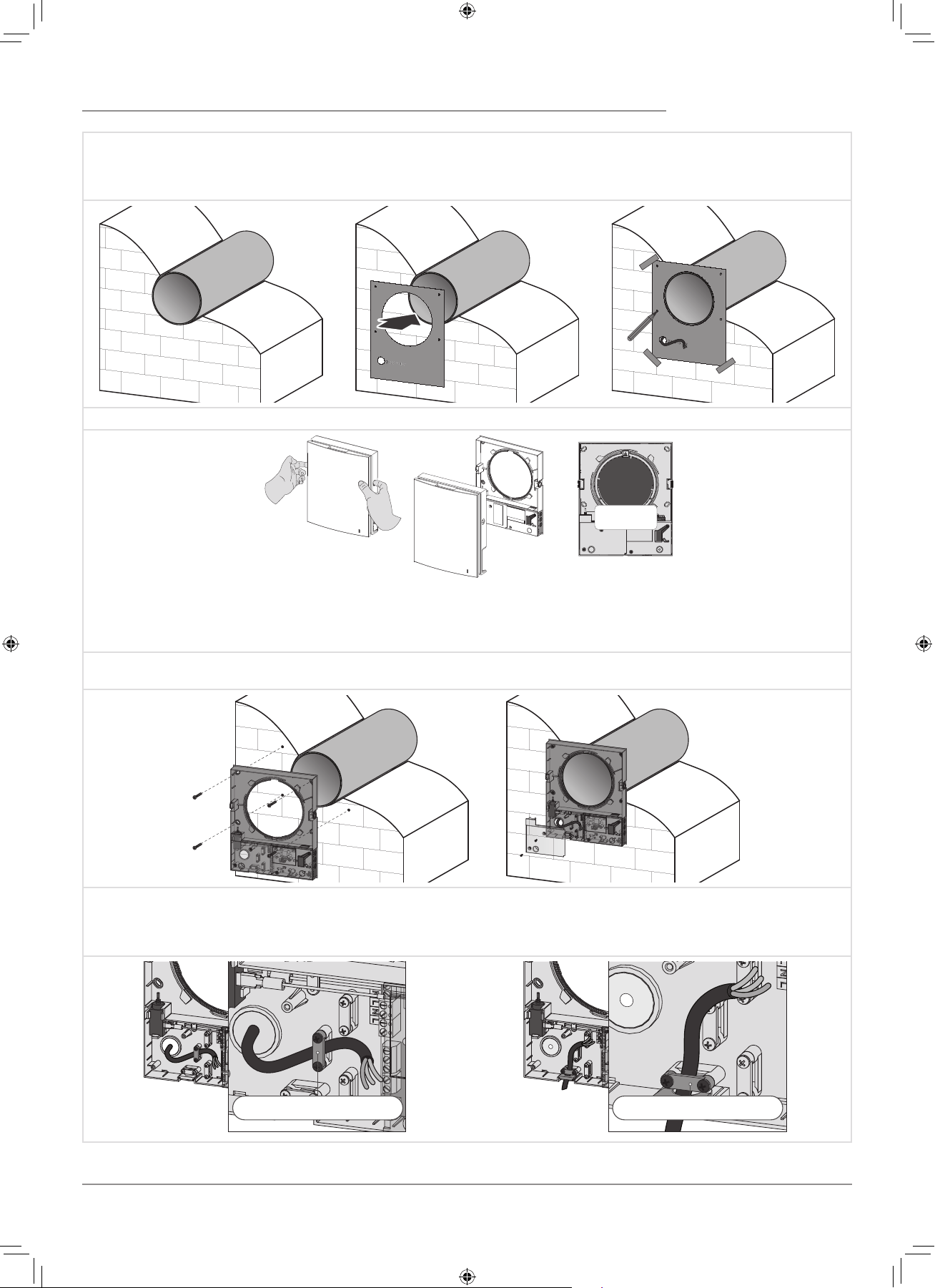
3. Stick the delivered cardboard master plate on the indoor wall using a mounting tape. The large opening in the master plate must
be axially aligned with the air duct. For aligning of the mater plate with respect to the horizon line it is recommended to use a builder’s
level. Then mark the fastening holes for installation of the supplied dowels and drill the holes to a required depth. Route the power
cable from the wall outside through the specially marked opening on the master plate.
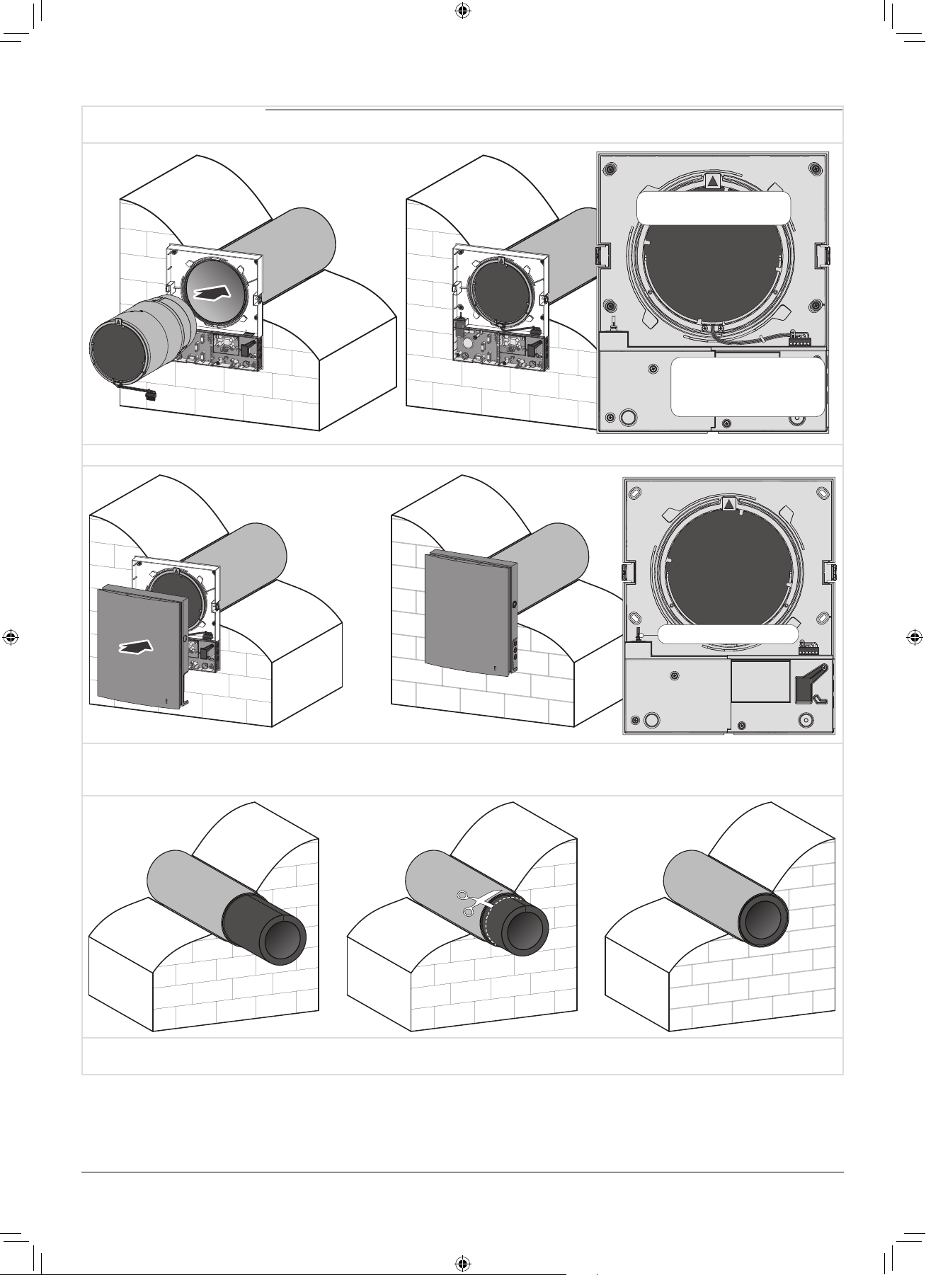
4. Press the side latches to detach the front part of the indoor assembly unit from its back part.
While installing the front
panel the thermal actuator
rod must be in low position.
5. Fix the back part of the indoor assembly unit on the wall with the screws supplied with the mounting kit of the ventilator. Remove
the two retaining screws from the left transparent cover to enable access to the terminals.
6. Route the power cable as figured below and connect the ventilator to power mains in compliance with the external wiring diagram,
refer Page 11.
Fix the power cable and the signalling cables with a cable clamp. After completion of the electrical connection re-install the transparent
cover in site.
Cable clamp Cable clamp
F112EN-02.indd 9 05.10.2015 16:10:03
10
7. Insert the cartridge into the air duct as figured below. The pointer must be directed upwards.
Then fix the wire with the protruding clamp and connect the socket connector to the circuit board.
Insert the wires under the
cable clamp and connect
the socket connector to the
circuit board.
The pointer must be
directed upwards.
8. Install the front part of the indoor assembly unit.
Thermal actuator rod
9. Install the sound absorbing layer on the outer side. Roll the layer of the sound absorbing material to match the air duct diameter.
The protecting paper layer must be outside. Insert the sound absorbing roll into the cartridge against stop.Mark the end of the sound
absorbing roll to be flush with the air duct edge and cut the excess.Insert the ready sound absorbing roll into the air duct.
10. Install the outer ventilation hood. The mounting sequence of the outer ventilation hood is described in the installation instruction
for the ventilation hood.
F112EN-02.indd 10 05.10.2015 16:10:09
11
CONNECTION TO POWER MAINS AND CONTROL
The ventilator is rated for connection to single-phase ac 100-240 V/ 50-60 Hz power mains.
The routing of the power and signalling cables is shown in Mounting and Set-Up, Page 9.
For electric installations use insulated, durable and heat-resistant electric leads (cables, conductors) with the minimum cross section
0.5 up to 0.75 mm2 for the power cable and 0.25 mm2 for the signalling cables.
The above value is tentative.
The signalling cable must be shielded.
While selecting the required cable cross section consider the cable type, its maximum heating temperature, insulation, length and
installation method.
Use copper wires for all the electric connections!
Connect the unit to power mains via the terminal block installed in the control circuit in compliance with wiring diagram and terminal
designation.
Connect the unit to power mains via a thermal magnetic circuit breaker, integrated into a house cabling system.
The trip current of the circuit breaker must exceed the ventilator current consumption, refer Table 5.
The ventilator design enables connecting any external controls with
a normally opened contact (NO-contact), such as an external CO2 sensor,
humidity sensor, relay switch, etc.
When the contact NO1 and NO2 closes the ventilator switches to high
speed.
Several ventilators may be in series or parallel connected to power mains
with a central control by the master ventilator.
In case of in-series or parallel connection of several ventilators power is
supplied either from a previous ventilator or from power mains.
DISCONNECT THE UNIT FROM POWER SUPPLY PRIOR TO ANY ELECTRIC INSTALLATION
OPERATIONS.
INSTALLATION SHALL ONLY BE PERFORMED BY A PROFESSIONAL ELECTRICIAN
QUALIFIED FOR UNASSISTED OPERATIONS WITH ELECTRICAL INSTALLATIONS UP TO
1000 V AFTER CAREFUL STUDY OF THE PRESENT USER’S MANUAL.
THE RATED ELECTRICAL PARAMETERS ARE STATED ON THE RATING PLATE.
ANY TAMPERING WITH THE INTERNAL CONNECTIONS IS PROHIBITED AND WILL
VOID THE WARRANTY.
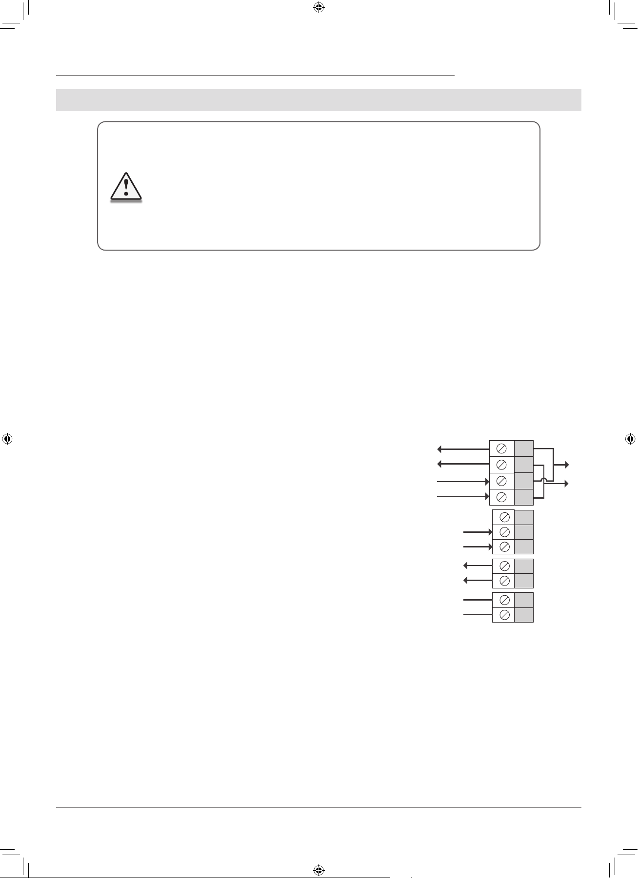
N
L
N
L
In
Gnd
Gnd
Out
NO1
NO2
+12V
Power output
100-230 V / 50-60 Hz
Power input
100-230 V / 50-60 Hz
to the ventilator
Control signal input from
a previous ventilator
Control signal output to
next ventilator
NO-contact for connection
of external controls
EXTERNAL WIRING DIAGRAM
F112EN-02.indd 11 05.10.2015 16:10:11
12
N
L
N
L
In
Gnd
Gnd
Out
NO1
NO2
+12V
N
L
N
L
In
Gnd
Gnd
Out
NO1
NO2
+12V
N
L
N
L
In
Gnd
Gnd
Out
NO1
NO2
+12V
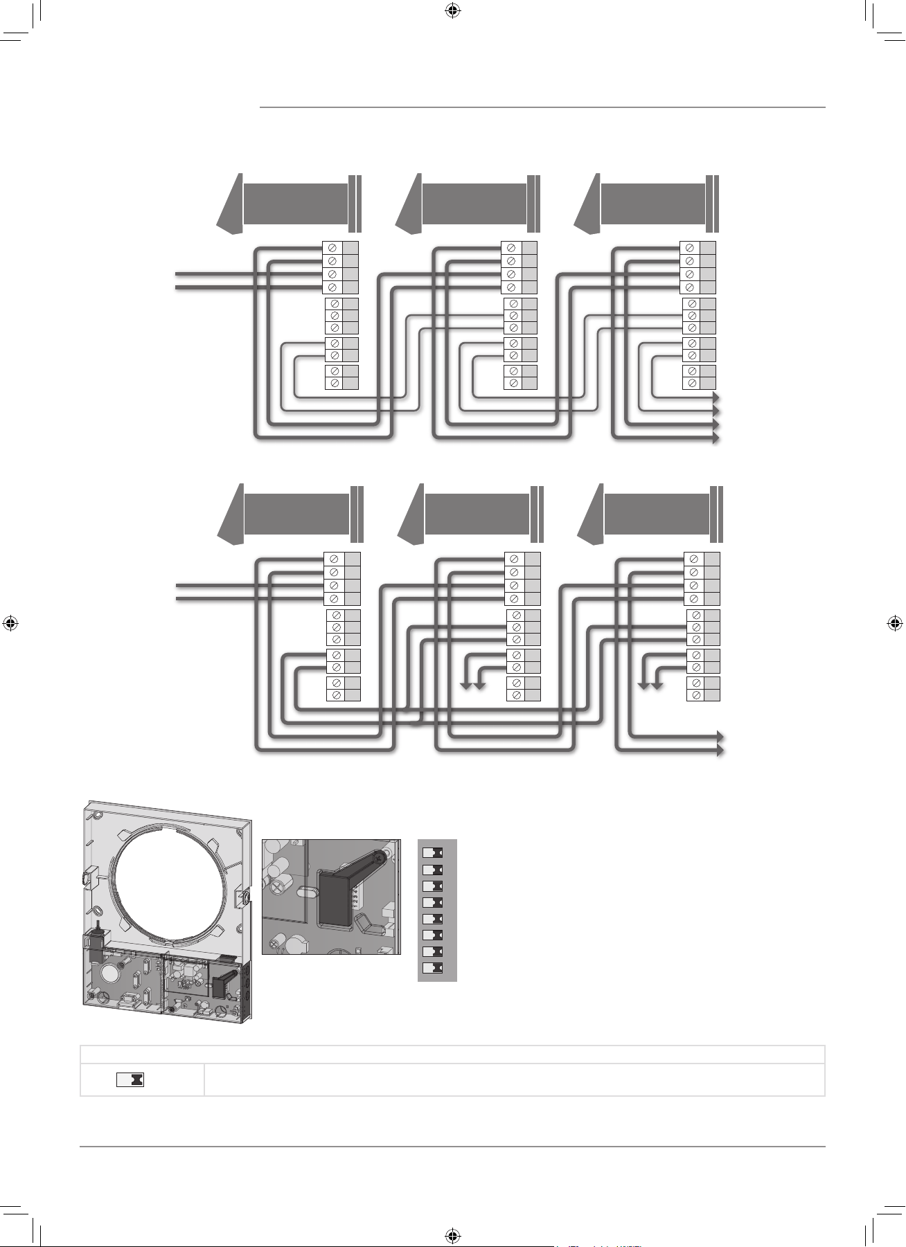
Master Slave 1 Slave N
Power input
100-230 V / 50-60 Hz
to the next ventilator
Master Slave 1 Slave N
N
L
N
L
In
Gnd
Gnd
Out
NO1
NO2
+12V
N
L
N
L
In
Gnd
Gnd
Out
NO1
NO2
+12V
N
L
N
L
In
Gnd
Gnd
Out
NO1
NO2
+12V
Power input
100-230 V / 50-60 Hz
to the next ventilator
WIRING DIAGRAM FOR IN-SERIES CONNECTION
WIRING DIAGRAM FOR PARALLEL CONNECTION
Prior to operating the ventilator set up the ventilator
using the DIP-switch. It is located on the controller circuit
board.
To access the DIP-switch take off the front panel of the
indoor assembly unit and uplift the rubber protective cap
that covers the switch.
VENTILATOR SET-UP
Open the rubber protective cap.
DIP-switch under the
rubber protective
cap.
1 2 3 4 5 6 7 8
DIP-SWITCH POSITIONING
1
Turning the ventilator off is allowed.
The switch position enables deactivation of the ventilator with the button on the side control panel.
F112EN-02.indd 12 05.10.2015 16:10:17
13
1
Turning the ventilator off is not allowed.
The switch position disables deactivation of the ventilator with the button on the side control panel.
Fan rotation direction:
For controlled ventilation it is recommended to install the ventilators pairwise and integrate them in a group using a signalling cable.
Set one half of the connected ventilators into supply mode and the other half into extract mode.
2
Air supply
This positioning of the switch enables supply operation of the ventilator in Ventilation mode.
In Regeneration mode the ventilator starts operating first in supply mode.
2
Air extract.
This positioning of the switch enables extract operation of the ventilator in Ventilation mode.
In Regeneration mode the ventilator starts operating first in extract mode.
Humidity sensor setpoint
The humidity sensor measures the extract air humidity.
If the extract air humidity is above the set point, the ventilator switches to high speed.
As humidity drops down to the set point, the ventilator changes to pre-set speed after elapsing of the run-out time.
Humidity sensor
setpoint
Humidity setpoint
40 %
Humidity setpoint
50 %
Humidity setpoint
60 %
Humidity setpoint
70 %
Humidity setpoint
80 %
3 4 5
3 4 5
3 4 5
3 4 5
3 4 5
3 4 5
Run-out timer
During activation of the humidity sensor or any other control unit the ventilator switches to higher speed.
After standardization of the indoor humidity or any other air parameters the ventilator returns to a previously set mode in set
time period.
Turn-on delay time
0 min.
Turn-on delay time
5 min.
Turn-on delay time
15 min.
Turn-on delay time
30 min.
6 7
6 7
6 7
6 7
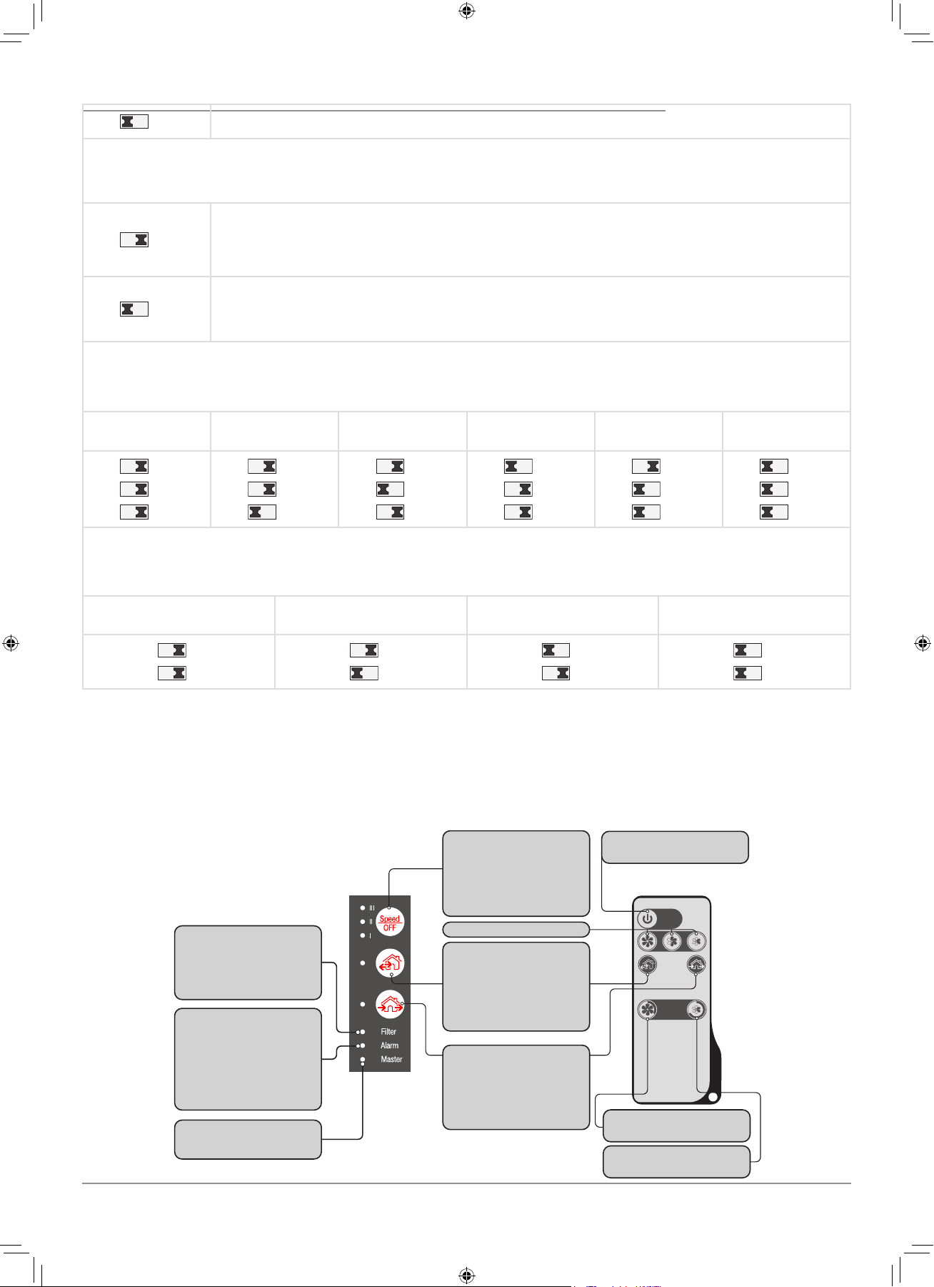
Turning ventilator
on/off
Activation of high speed
for 3 hours
Activation of low speed
for 8 hours
Speed setting
Ventilation mode
The ventilator operates either in
extract or supply mode at set speed
depending on positioning of the
DIP-switch on the circuit board.
Filter indicator
After the set filter replacement
periodicity has expired the Filter
indicator starts glowing.
In this case clean or replace the
filters.
Alarm indicator
In case of the motor jam the Alarm
indicator starts glowing and the
ventilator stops.
All the connected in series ventila-
tors stop synchronically.
Master indicator
Indicator of the first ventilator in the
group.
Regeneration mode
Air flow direction changes once in
70 seconds and the ventilator
changes between supply and extract
mode.
Heat regeneration is performed in
this mode.
Speed/off
The speed setting engages
cyclically: I-II-III-Off.
A respective indicator starts
glowing during speed setting.
Buttons on the
ventilator casing
Remote control
VENTILATOR CONTROL
The ventilator can be operated with the remote control or the control buttons on the side part of the indoor assembly unit, as
figured below.
In case of in-series or parallel connection the signal from a control unit is received by the first ventilator (Master) only.
F112EN-02.indd 13 05.10.2015 16:10:18
14
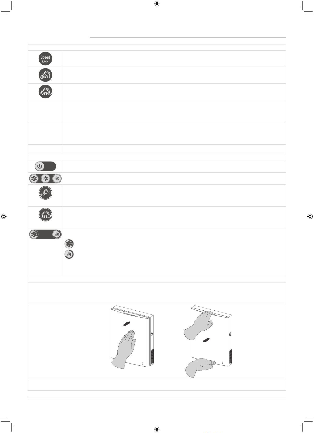
VENTILATOR CONTROL WITH THE BUTTONS ON THE INDOOR ASSEMBLY UNIT
The speed setting engages cyclically: I-II-III-Off.
All the connected in series ventilators synchronise their speed with the first ventilator in the group.
Regeneration mode
The ventilator operates 70 seconds in supply mode and 70 seconds in extract mode.
Heat regeneration is performed in this mode.
Ventilation mode.
The ventilator operates exclusively either in supply or in extract mode.
The air flow direction depends on positioning of the DIP-switch-2 (set to air extract by default).
Filter
Filter
Filter clogging indicator. 90 days after installation of the cartridge the Filter clogging indicator starts glowing.
In this case clean or replace the filters. For details, refer to the Maintenance Section. During in-series connection the
first ventilator indicator has a steady glow and the indicator of the ventilator requiring filter replacement blinks.
Alarm
Alarm
Motor jam indicator. In case of the motor jam the Alarm indicator starts glowing and the ventilator stops.
All the connected in series ventilators stop synchronically. During in-series connection the first ventilator
indicator has a steady glow and the indicator of the ventilator with a jammed motor blinks.
Master
Indicator of the first ventilator in the group.
VENTILATOR CONTROL WITH THE REMOTE CONTROL
Turning ventilator on/off
The ventilator turning off is possible if the DIP-switch-1 is set to a respective position.
The speed setting engages cyclically: III-II-I.
Regeneration mode
Air flow direction changes once in 70 seconds and the ventilator changes between supply and extract mode.
Heat regeneration is performed in this mode.
The button is doubled on the indoor assembly unit.
Ventilation mode
The ventilator operates exclusively either in supply or in extract mode.
The air flow direction depends on positioning of the DIP-switch-2 (set to air extract by default).
The button is doubled on the indoor assembly unit.
Timer buttons:
— Activation of high speed for 3 hours
— Activation of low speed for 8 hours
Upon expiration of the set time period the ventilator reverts to a pre-set speed.
Press any button of the manual speed setting to deactivate the timer.
AIR FLOW BLOCKING
Press the front panel gently to cut off the air duct.
The ventilator will turn off.
To open the air duct pull the front panel while holding the special latches.
The ventilator reverts to the pre-set operation mode that was active before the air duct cut-out.
Air duct
blocking
Air duct
opening
The operating LED light is incoprorated in the front panel. During the dark time the indicator light intensity drops down.
F112EN-02.indd 14 05.10.2015 16:10:20
15
MAINTENANCE
DISCONNECT THE UNIT FROM POWER SUPPLY
BEFORE ANY MAINTENANCE OPERATION WITH THE UNIT.
Maintenance of the ventilator means regular cleaning of the ventilator surfaces of dust and cleaning or replacement of the filters.
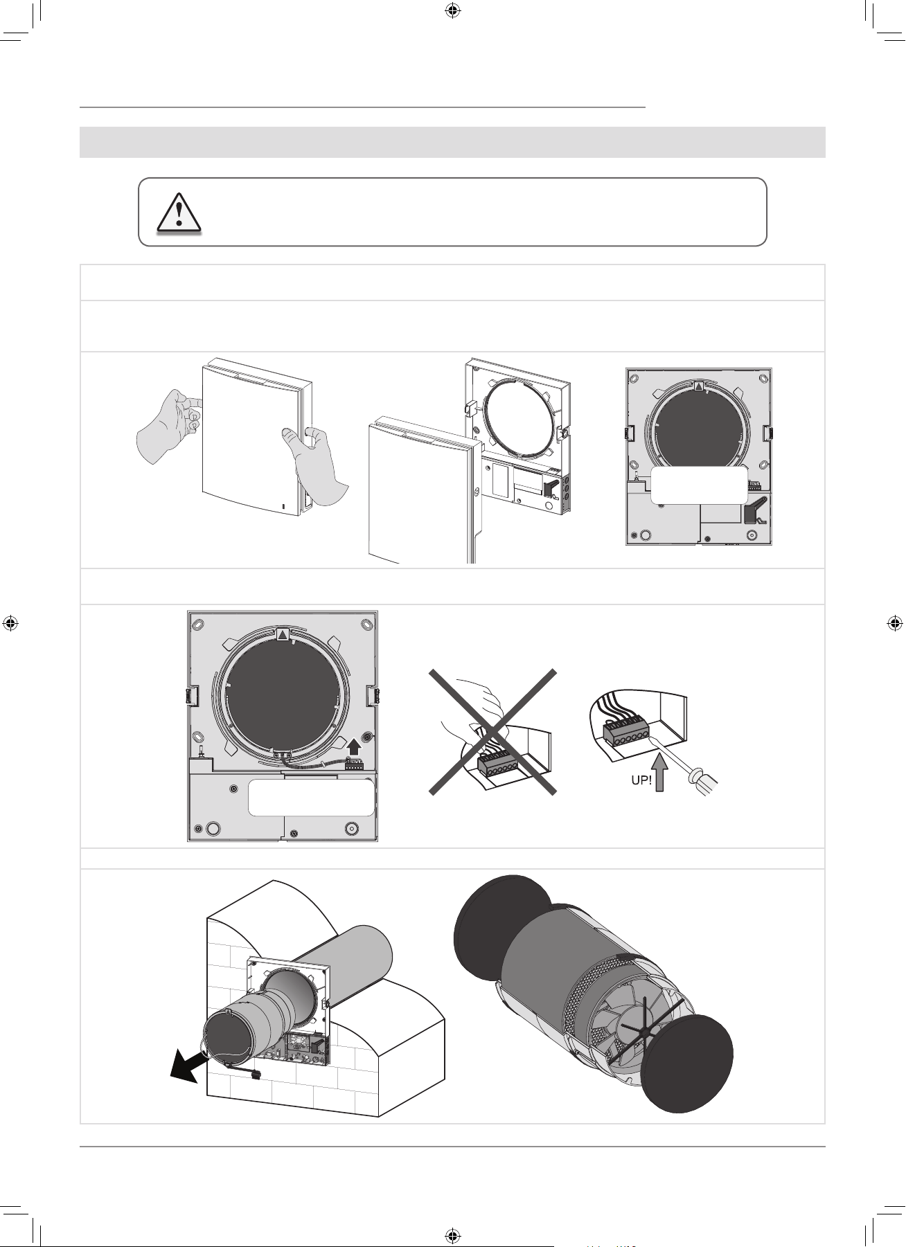
To access the basic assembly units follow the steps:
1. Press the latches on the side of the indoor assembly unit to take off the front part.
When re-installing the front panel the thermal actuator rod must be down. If it is uplifted, wait until it goes down about
2 minutes.
While installing the front
panel the thermal actuator
rod must be in low position.
2. Remove the socket connector from the circuit board. While removing the socket connector do not pull the cable. Uplift it with a
flat screw driver of a respective size.
Disconnect the socket con-
nector from the circuit
board.
Use a flat screwdriver to
disconnect the socket
connector.
Do not pull the wires!
3. Pull the cord to remove the cartridge from the air duct. Remove the filters from the cartridge.
F112EN-02.indd 15 05.10.2015 16:10:23
16
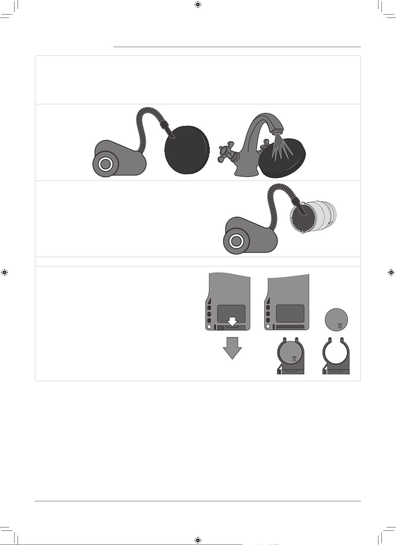
Clean the filters as often as those gets soiled, but at least 3-4 times a year.
• After the set filter replacement periodicity has expired the Filter indicator starts glowing.
• The filter timer is reset once the socket connector of the cartridge is disconnected from the circuit board.
• Wash the filters and let them get dry. Install dry filters in the air duct.
• Vacuum cleaning is allowed.
• The filter is rated for three years operation.
• Contact the Seller for spare filters.
Even regular technical maintenance may not completely prevent dirt
accumulation on the regenerator.
• Clean the regenerator regularly to ensure its high heat
recovery efficiency.
• Clean the regenerator with a vacuum cleaner at least once in
year.
4. Battery replacement in the remote control (as often as required).
In case of a long operation of the remote control the battery
must be replaced.
No response of the ventilator for pressing the remote control
buttons indicates the need to replace the battery.
The battery type is CR2025.
Remove the holder with the battery from the lower part of the
remote control.
Then replace the battery and re-install the holder with a new
battery in site.
+
CR2025
3V
+
CR2025
3V
F112EN-02.indd 16 05.10.2015 16:10:24

17
POSSIBLE FAULTS AND TROUBLESHOOTING
Fault Possible reasons Remedy
The fan does not start
up during start-up of the
ventilator.
No power supply.
Make sure that the ventilator is properly
connected to power mains and make any
corrections, if necessary.
Motor is jammed, the impeller blades are clogged.
Turn the ventilator off.
Troubleshoot the motor jam and the impeller
clogging. Clean the blades.
Restart the ventilator.
Circuit breaker tripping
during the ventilator start-
up.
Overcurrent as a result of short circuit in the
electric circuit.
Turn the ventilator off.
Contact the Seller for further information.
Low air flow.
Low set fan speed. Set higher speed.
The filters, the fan or the regenerator is soiled.
Clean or replace the filter. Clean the fan and the
regenerator.
High noise, vibration.
The impeller is soiled. Clean the impeller.
Loose screw connection of the ventilator casing
or the outer ventilation hood.
Tighten the screws of the ventilator or the outer
ventilation hood.
TROUBLESHOOTING
STORAGE AND TRANSPORTATION REGULATIONS
Store the unit in the manufacturer’s original packing box in a dry ventilated premise at ambient temperatures from +5 ˚C ( +41 ˚F) up
to +40 ˚C (104 ˚F).
Storage environment must not contain aggressive vapours and chemical mixtures provoking corrosion, insulation and sealing
deformation.
Use suitable hoist machinery for handling and storage operations to prevent possible damage to the unit.
Follow the handling requirements applicable for the particular type of cargo.
The unit can be carried in the original packing by any mode of transport provided proper protection against precipitation and mechanical
damage.
Avoid sharp blows, scratches or rough handling during loading and unloading.
F112EN-02.indd 17 05.10.2015 16:10:24
18
The manufacturer hereby warrants normal operation of the unit for 24 months after the retail sale date provided the user’s observance
of the transportation, storage, mounting and operation regulations.
Should any malfunctions occur in the course of the unit operation through the Manufacturer’s fault during the guaranteed period of
operation the user is entitled to elimination of faults by the manufacturer by means of warranty repair at the factory free of charge.
The warranty repair shall include work specific to elimination of faults in the unit operation to ensure its intended use by the user within
the guaranteed period of operation.
The faults are eliminated by means of replacement or repair of the unit components or a specific part of such unit component.
The warranty repair does not include:
• Routine technical maintenance;
• Unit installation / dismantling;
• Unit setup.
To benefit from warranty repair the user must provide the unit, the user’s manual with the purchase date stamp and the payment
document certifying the purchase.
The unit model must comply with the one stated in the user’s manual.
Contact the Seller for warranty service.
The manufacturer’s warranty does not apply to the following cases:
• User’s failure to submit the unit with the entire delivery package as stated in the user’s manual including submission with missing
component parts previously dismounted by the user.
• Mismatch of the unit model and the brand name with the information stated on the unit packing and in the user’s manual.
• User’s failure to ensure timely technical maintenance of the unit.
• External damage to the unit casing (excluding external modifications as required for installation) and internal components caused
by the user.
• Redesign or engineering changes to the unit.
• Replacement and use of any assemblies, parts and components not approved by the manufacturer.
• Unit misuse.
• User’s violation of the unit installation regulations.
• User’s violation of the unit control regulations.
• Unit connection to the power mains with a voltage different from the one stated in the user’s manual.
• Unit breakdown due to voltage surges in the power mains.
• Discretionary repair of the unit by the user.
• Unit repair by any persons without the manufacturer’s authorization.
• Expiration of the unit warranty period.
• User’s violation of the unit transportation regulations.
• User’s violation of the unit storage regulations.
• Wrongful actions against the unit committed by third parties.
• Unit breakdown due to circumstances of insuperable force (fire, flood, earthquake, war, hostilities of any kind, blockades).
• Missing seals if provided by the user’s manual.
• Failure to submit the user’s manual with the unit purchase date stamp.
• Missing payment document certifying the unit purchase.
MANUFACTURER’S WARRANTY
FOLLOWING THE REGULATIONS STIPULATED HEREIN WILL ENSURE
A LONG AND TROUBLE-FREE OPERATION OF THE UNIT.
USERS’ WARRANTY CLAIMS SHALL BE SUBJECT TO REVIEW ONLY
UPON PRESENTATION OF THE UNIT, THE PAYMENT DOCUMENT AND
THE USER’S MANUAL WITH THE PURCHASE DATE STAMP.
F112EN-02.indd 18 05.10.2015 16:10:24
19
ACCEPTANCE CERTIFICATE
SELLER INFORMATION
INSTALLATION CERTIFICATE
Unit Type The single-room reversible energy regeneration ventilator
Model TwinFresh Expert _______
Serial Number
Manufacture Date
Is compliant with the technical specifications and is recognized as serviceable. We hereby declare that the product complies with
the essential protection requirements of Electromagnetic Council Directive 2004/108/EC, 89/336/EEC and Low Voltage Directive
2006/95/EC, 73/23/EEC and CE-marking Directive 93/68/EEC on the approximation of the laws of the Member States relating to
electromagnetic compatibility.
This certificate is issued following test carried out on samples of the product referred to above.
Quality Inspector’s
Stamp
Outlet Name
Address
Phone Number
E-mail
Purchase Date
Seller’s Stamp
Installation Company Stamp
This is to certify acceptance of the complete ventilator delivery with the user's manual. The warranty
terms are acknowledged and accepted.
Customer's Signature
The single-room reversible energy regeneration ventilator TwinFresh Expert _________has been
connected to power mains pursuant to the requirements stated in the present user’s manual.
Discretionary repair of
the unit by the user.
Address
Phone Number
Installation
Technician's Full Name
Installation Date: Signature:
The ventilator has been installed in accordance with the provisions of all the applicable local and national
construction, electrical and technical codes and standards.
Signature:
F112EN-02.indd 19 05.10.2015 16:10:24

F112EN-02
WARRANTY CARD
Seller’s Stamp
Unit Type The single-room reversible energy regeneration ventilator
Model TwinFresh Expert ______________
Serial Number
Manufacture Date
Purchase Date
Warranty Period
Seller
F112EN-02.indd 20 05.10.2015 16:10:24