
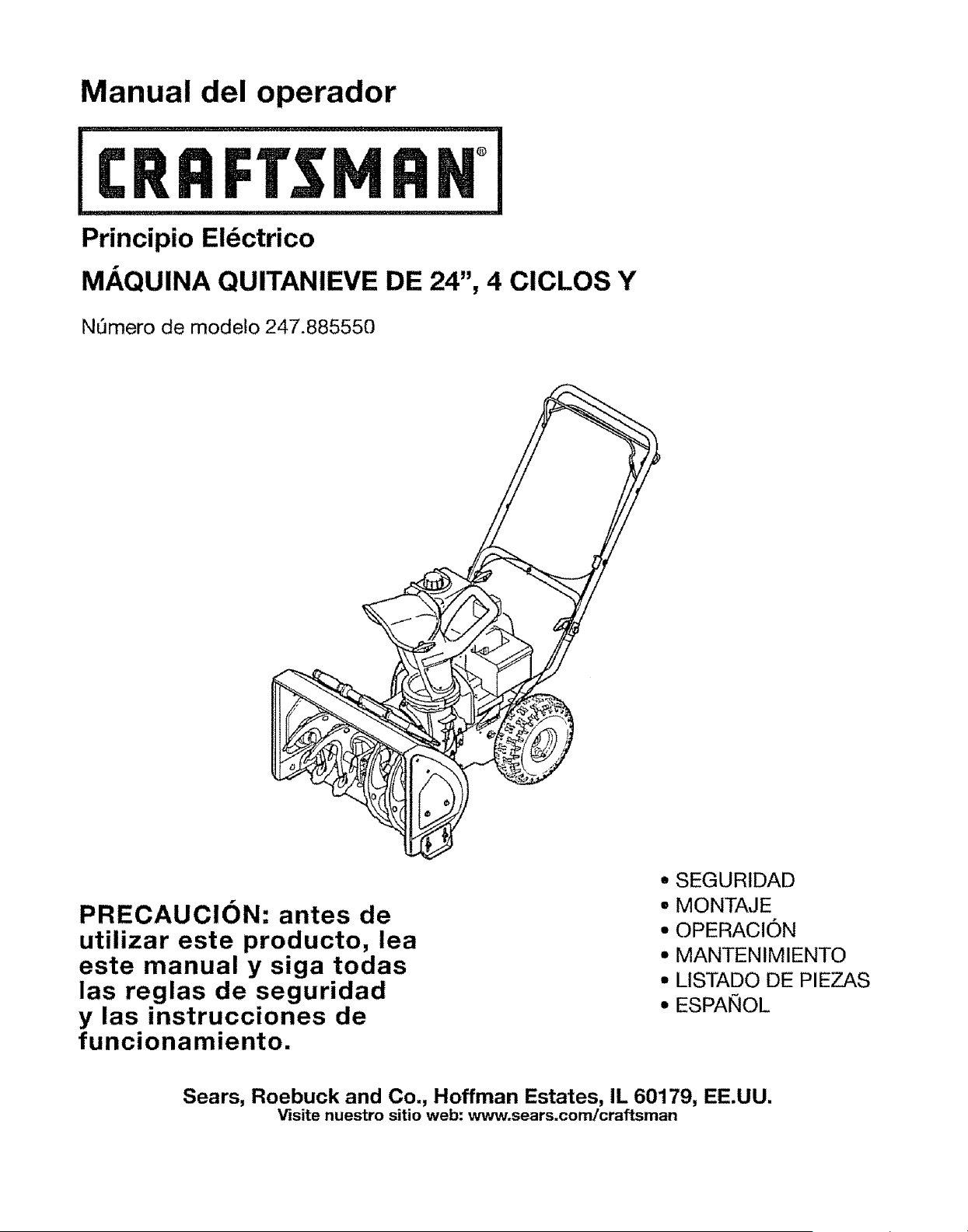
Operator's Manual
®
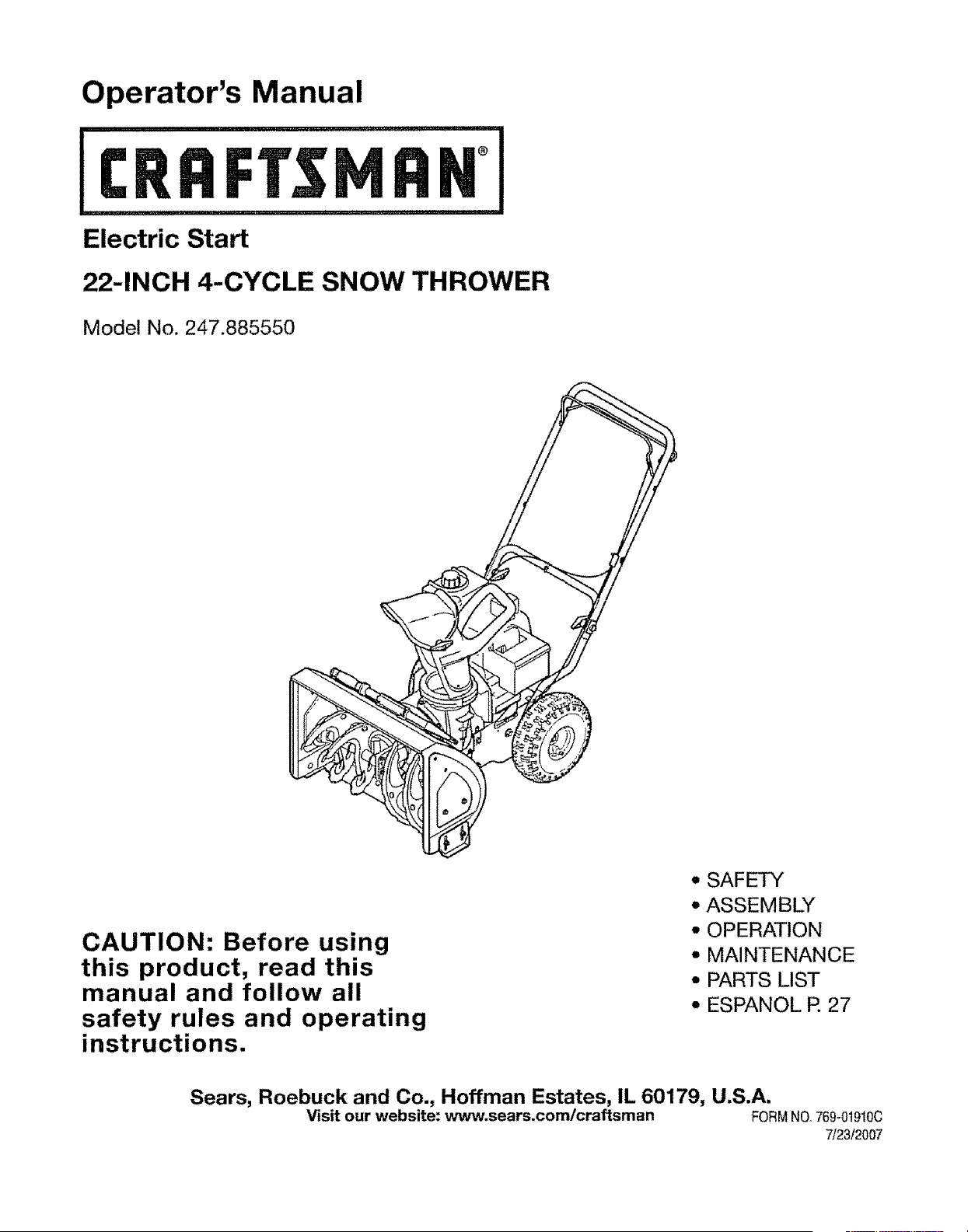
Electric Start
22-INCH 4-CYCLE SNOW THROWER
Model No. 247.885550
CAUTION: Before using
this product, read this
manual and follow all
safety rules and operating
instructions.
• SAFETY
• ASSEMBLY
• OPERATION
• MAINTENANCE
• PARTS LIST
• ESPANOL P. 27
Sears, Roebuck and Co., Hoffman Estates, IL 60179, U.S.A.
Visit our website: www.sears.com/craftsman FORMNO,,769-0t910C
7/23/2007
WarrantyStatement.........................................................................Page2
SafetyLabels.......................................................................................Page3
RulesofSafeOperation...........................................................Pages4-5
SetUp&Adjustment......................................................Pages6-7
KnowYourSnowThrower............................................Pages8-9
Operation..............................................................................Pages10-11
Maintenance and Service ..........................................................Pages 12-15
Off Season Storage & Troubleshooting ...............Page 16-17
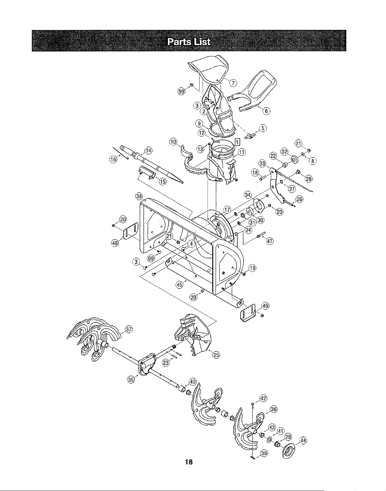
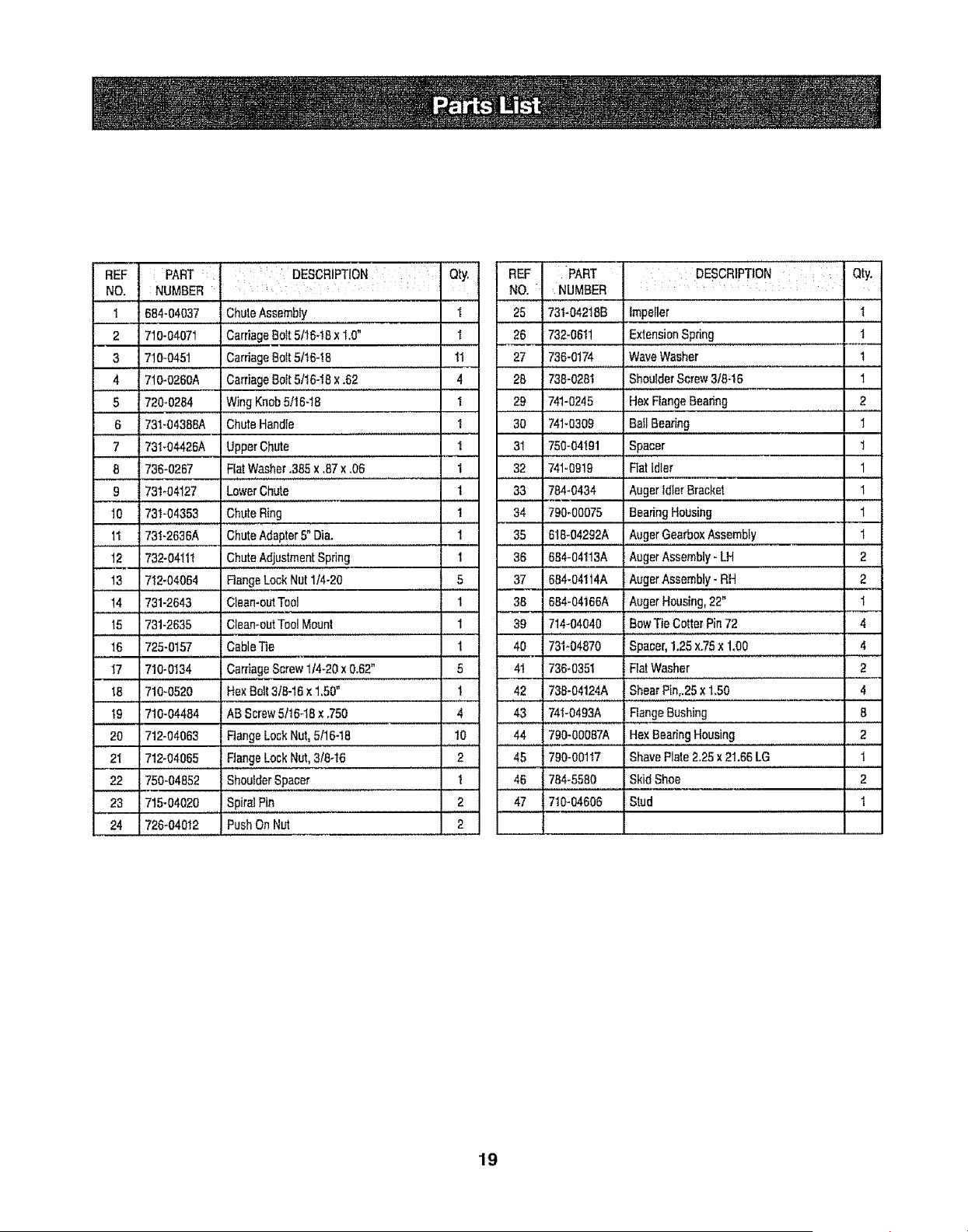
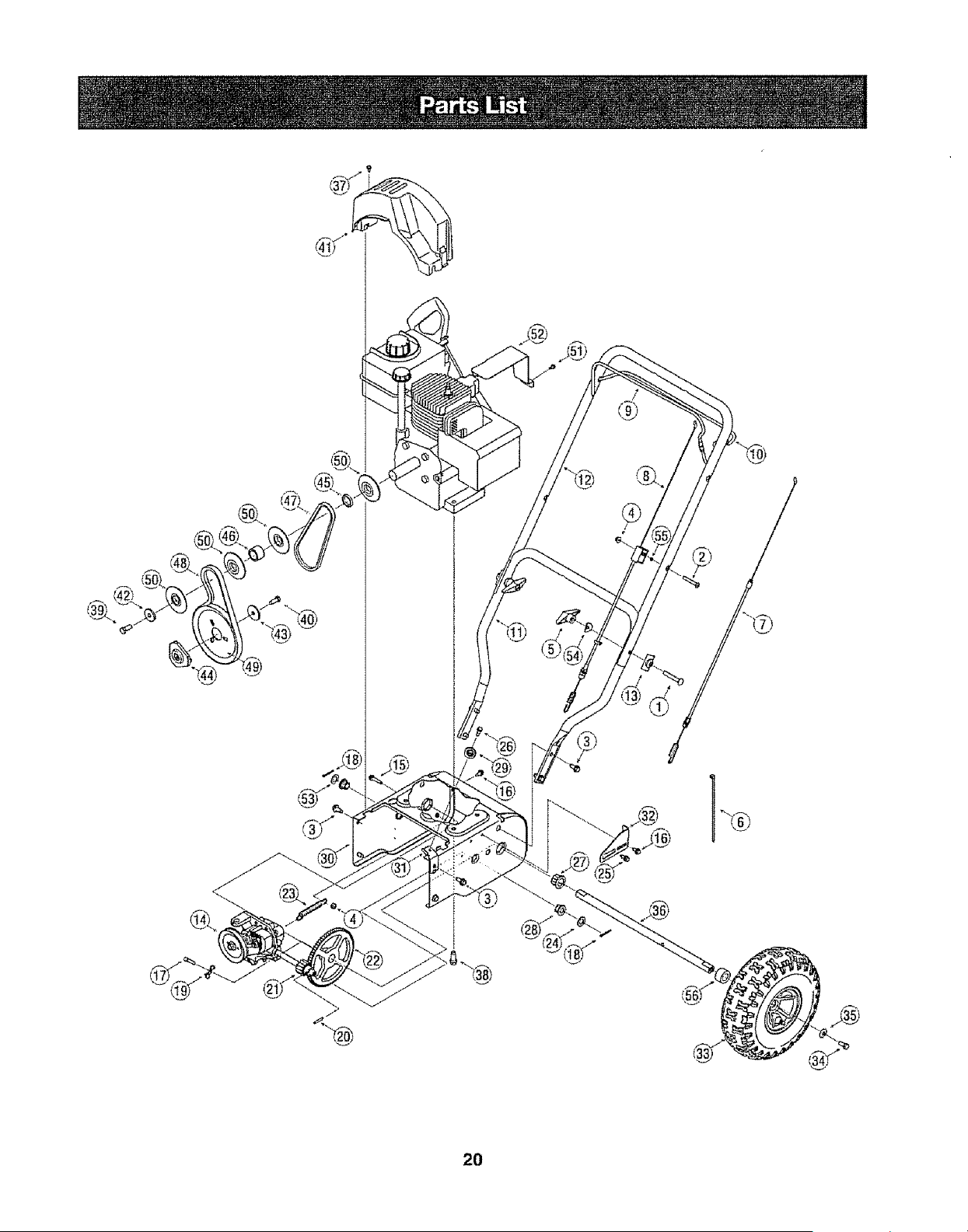
Parts List .....................................................................Pages 18-25
EspaEol ............................................................................Page 27
Service Numbers ......................................................................Back Cover
Two-YearWarrantyonCraftsmanSnowThrower
Fortwoyearsfromthedateof purchase,whenthisCraftsmanSnowThrowerismaintained,fubricatedandtunedupaccordingto theinstructions
inthe owner'smanual,Searswirlrepair,freeof charge,anydefectinmaterialandworkmanship.If thisCraftsmansnowthroweris usedfor
commercialor rentalpurposes,this warrantyappliesforonly30daysfromthedateofpurchase..
Thiswarrantydoesnotcover:.
• Expendableitemswhichbecomewornduringnormaluse,suchas skid shoes,shaveplateandsparkplugs.
• Repairsnecessarybecauseof operatorabuseornegligence,includingbentcrankshaftsandthefailureto maintainthe equipmentaccording
to theinstructionscontainedinthe owner'smanual.
WARRANTYSERVICEISAVAILABLEBYRETURNINGTHECRAFTSMANSNOWTHROWERTOTHE NEAREST
SEARSPARTS& REPAIRCENTERiNTHEUNITEDSTATES..
ThiswarrantyappliesonlywhilethisproductisinuseintheUnitedStates
TO LOCATETHENEARESTSEARSPARTS& REPAIRCENTERORTOSCHEDULESERVICE,
SIMPLYCONTACTSEARSAT1-800-4-MY-HOME®
Thiswarrantygivesyou specificIegalrightsandyoumayalsohaveotherrightswhichmayvaryfromstateto state
SEARS,ROEBUCKANDCO.,D/817WA,HOFFMANESTATES,IL 60179
RepairProtectionAgreements
CongratulationsonmakingasmartpurchaseYournewCraftsman®
productis designedandmanufacturedfor yearsof dependableopera-
tion.Butlikeallproducts,it mayrequirerepairfromtimetotime.That's
whenhavinga RepairProtectionAgreementcan saveyoumoneyand
aggravation
Here'swhat'sincludedin theAgreement:
, Expertserviceby our12,000professionalrepairspecialists
, Unlimitedserviceandnochargefor partsandlaboron all covered
repairs
• Productreplacementif yourcoveredproductcan'tbefixed
, Discountof 10%fromregularpriceof serviceandservice-related
partsnotcoveredbytheagreement;also,10%off regularpriceof
preventivemaintenancecheck
• Fasthelpbyphone- phonesupportfroma Searstechnicianon
productsrequiringin-homerepair,plusconvenientrepair
scheduling
Engine Oil:
Fue!:
Spark Plug:
Engine:
Purchasea RepairProtectionAgreementnowandprotectyourself
fromunexpectedhassleand expense
Onceyoupurchasethe Agreement,a simprephonecall isalfthatit
takesforyouto scheduleserviceYoucancallanytimedayor night,or
scheduleaserviceappointmentonline.
Searshasover12,000professionalrepairspecialists,whohave
accessto over4 5millionqualitypartsandaccessoriesThat'sthe
kindof
professionalismyoucancountonto helpprolongthe lifeof yournew
purchasefor yearsto come.PurchaseyourRepairProtectionAgree-
menttodayt
Somelimitations and exclusions apply,For prices andadditional
informationcall1-800-827-6655,
SearsInstallationService
ForSearsprofessionalinsta!lationof homeappliances,garagedoor
openers,waterheaters,andothermajorhomeitems,inthe USA. call
I_800-4-MY-HOME@
SAE 5W-30
Unleaded Gasoline
Champion® RJ19LM
Tecumseh LH195SP
Record the model number, serial number
and date of purchase above
I I
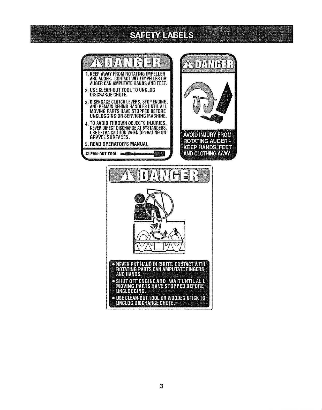
1. KEEPAWAYFROMROTATINGIMPELLER
ANDAUGER°CONTACTWITHIMPELLEROR
AUGERCANAMPUTATEHANDSANDFEET.
2. USECLEAN-OUTTOOLTOUNCLOG
DISCHARGECHUTE.
3. DISENGAGECLUTCHLEVERS,STOPENGINE,
ANDREMAINBEHINDHANDLESUNTILALL
MOVINGPARTSHAVESTOPPEDBEFORE
UNCLOGGINGORSERVICINGMACHINE.
4_TOAVOIDTHROWNOBJECTSINJURIES,
NEVERDIRECTDISCHARGEATBYSTANDERS.
USEEXTRACAUTIONWHENOPERATINGON
GRAVELSURFACES.
5. READOPERATOR'SMANUAL.,
CLEAN-OUTTOOL
lIIj Igr.llh l_ _l+:_!ql_I_IH:I_+;'_
Ii_ii_]H I1.,1,1t.lI_Iitii -_i!_']_II_I!!:|_I[i]liII|i]i]IIJ};Ir_!Jt]t]t]_I_I_ii[_]_'IIIII
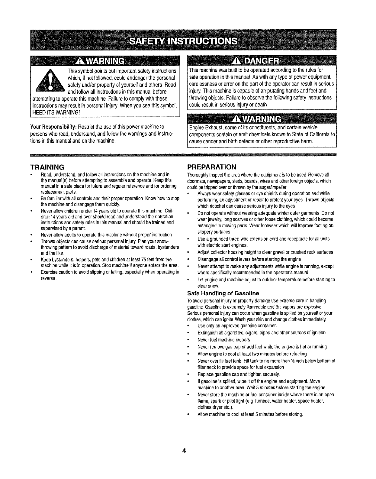
_IL Thissymbolpointsoutimportantsafetyinstructions
which,if notfollowed,couldendangerthe personal
safetyand/orpropertyofyourselfandothers Read
andfollowallinstructionsinthismanualbefore
attemptingto operatethismachineFailureto complywiththese
instructionsmayresultin personalinjury Whenyouseethis symbol,
HEED ITSWARNING!
YourResponsibility: Restricttheuseofthispowermachineto
personswhoread,understand,andfollowthewarningsandinstruc-
tionsinthismanualandonthemachine
Thismachinewasbuiltto beoperatedaccordingto the rulesfor
safeoperationin thismanualAs withanytypeof powerequipment,
carelessnessor erroronthe partofthe operatorcanresufIin serious
injury,Thismachineis capableof amputatinghandsandfeetand
throwingobjects Failuretoobservethefollowingsafetyinstructions
couldresultin seriousinjuryordeath
EngineExhaust,someof itsconstituents,andcertainvehicle
componentscontainoremil chemicalsknownto Stateof Californiato
I causecancerandbirthdefectsorolherreproductiveharm
TRAINING
• Road, understand, and follow air instruclionson the machine and in
the manual(s) before attempting to assembfe and operate Keep this
manual in a safe place for future and regular reference and for ordering
replacementparts
• Be familiar with afl controls and their proper operation Know how to stop
the machine and disengage them quickly
• Never atlow children under t4 years old to operate this machine Chi!-
dren 14 years old and over should read and understand the operation
instruclions and safety rules in lhis manual and should be trained and
supervised by a parent
• Never allowadults to operate this machine withoutproper instruction
• Thrown objects can cause serious personal injury Plan your snow°
Ihrowing pattern to avoid discharge of material toward roads, byslanders
and thelike
" Keep bystanders, helpers, pets and children at least 75 feet from the
machine while it is in operation, Stop machine if anyone enters the area
• Exercise caution to avoid slipping or falling, especially when operating in
reverse
PREPARATION
Thoroughly inspect the area wherethe equipment is to be used Remove all
doormats, newspapers, sleds, boards, wires and other foreign objects, which
could be trippedover or thrownby the augeriimpeller
• Always wear safety glasses or eye shields during operation and whiEe
performing an adjuslmenl or repair to protect your eyes Thrown obiects
which ricochet can cause serious injury to theeyes
• Do not operate withoutwearingadequate winler outer garments Do not
wear jewelry, Iong scarves or other loose clothing,whichcould become
entangled in moving pads Wear 'footwearwhich will improvefooling on
slippery surfaces
,, Use a grounded three-wire extension cord and receptacle for all units
with electric start engines
• Adjust collectorhousing height to clear gravel or crushed rocksurfaces,
• Disengage all control 1oversbefore starling the engine
• Never attempt to make any adjustmentswhile engine is running, except
where specifically recommendedin the operalor's manual
• Let engine and machine adjust to outdoor temperature before starling to
cleer SNOW,
Safe Handling of Gasoline
To avoid personal injury or property damage use extremecare in handling
gasoline Gasoline is extremely flammable and thevapors are explosive
Sedeus personal injury can occur whengasoline is spilled on yourself or your
clothes, whichcan ignile Wash your skin and change clothes immediately
• Use onty an approved gasoline container
• Exlinguish sit cigarettes,cigars, pipes and other sources of ignilion
• Never fuel machine indoors
• Never remove gas cap or add fuel whilethe engine is hot or running
• Allow engine to coolatleast two minutes before refueling
• Never over fltl fuel tank Fitltank to no more than _hinch below bottom of
filter neck to provide space for fuel expansion
• Replace gasoline cap and tighten securely
• If gasoline is spiIled,wipe it off the engine and equipment, Move
machine to another area Wail 5 minutes before starting the engine
• Never store the machine OFfuel containerinside where there is an open
flame, spark or pilot light (e g furnace, water heater, space heater,
clothes dryer ere,r),,
• Allow machine to cool at least 5 minutes before storing
4
OPERATION
" Do not put bands or feet near rotating parts, in the auger!impeller
housing or chute assembly Contact wilb the rotatingparts can amputate
hands and feet.
• The augedimpeUer control lever is a safety device Never bypass its
operetion_ Doing so makes the machine unsafe and may cause personal
injury
• The control levers must operate easily in both directionsand automatl-
calty return to the disengaged position when released
• Never operate with a missing or damaged chute assembly Keep all
safety devices in place and working
• Never run an engineindoorsor in a poorlyvenlitated area Engine
exhaustcontains carbon monoxide, an odorless and deadly gas
,, Do not operate machine while under the influence of a!eohol or drugs
• Muffler and engine become hot and can cause a bum Do nat touch
. Exercise extreme caution when operatingon or crossing gravel surfaces
Stay alert for hidden hazards or traffic
,, Exercise cautionwhen changing direction and whiteoperatingon slopes
• Ran your snow-throwing patternto avoid discharge towards windows,
wails, cars eta Thus, avoiding possible propertydamage or personal
injury caused by a ricochet
• Never direct discharge at children, bystanders and pets or allow anyone
infront ofthe machine
• Do not evedoad machine capacity by attempting to clear snow at too fast
of a rate.
• Never operate thismachine withoutgood visibility or light Always be
sure of your footing and keep a firm hold on the handles Walk, never
tun,
• Disengage powerto the augedimpeller when transporting or not in use
,, Never operate machine at high transport speeds on slipper] surfaces
Look down and behind and use care when backing up
• If the machine should start to vibrate abnormally, slop the engine.
disconnect the spark plugwire end ground itagainst the engine Inspect
theroughfyfor damage Repair any damage before starting and operat-
ing
• Disengage all control levers and stop enginebefore you Ieave the
operating position(behind the handles) Wait until the auger/impel}or
comes to a cempiete stop before unclogging the chute assembly, making
any adjustments, or inspections
,, Never put your hand in the discharge or collector openings, Always
use the clean-outtool prevldedto unclog the discharge opening Do
not unclog chute assembly while engine is running Shut off engine
and remain behind handles until ell moving parts have stepped before
unclogging
• Use only attachments and accessories approved by 1hemanufacturer
(e g whoa! weights, tire chains, cabs etc )
• ff situafions occur which are not covered inthis manual, use care and
good judgment Conlact your Sears Service Center for assistance_
MAINTENANCE & STORAGE
• Never tamper withsafety devices Check theirproperoperation
regufarly Refer to the maintenance end adjustment sections of this
manual
• Before cleaning, repairing, or inspecting machine disengage all control
levers and stop the engine Wait until the auger_mpeller cometo a
complete stop Disconnect the spark plug wire and ground against the
engine to prevent unintended starting
• Check bo_tsand screws for propertightness at frequent intervalsto keep
the machine in safe workingcondition Also, visually inspectmachine for
any damage
. Do not change the engine governor setting or over-speed the engine
The governorcontrolsthe maximumsafe operating speed of the engine
• Snow thrower shave plates and skid shoes are subject to wear and
damage For your safety protection, frequentlycheck al!components
end replace with original equipmenlmanufacturer's (OEM) parts only
"Use of parts which do not meet the origina! equipment specifications
may lead to improper performanceand compromise safety!"
• Check controls periodically to verify they engage and disengage
properlyand adjust, if necessary Refer to the adjustment section in th;s
operators manual for instructions
• Maintain or replace salety and instruction labels, as necessary
,, Observe proper disposal laws and regulations for gas, oil, etc to protest
the environment
• Pdor to storing, run machine a few minutes to clear snow from machine
and prevent freeze up of auger/impeller
• Never store the machine or fuelcontainer inside where there is an open
flame, spark or pilol fight such as a waterheater,furnace, clothes dryer
etc
• Always referto the operalor's manual for proper instructions on
off-season storage
Do not modify engine
Toavoidseriousinjuryordeath,do not modifyengineinanywayTampering
withthegovernorsettingcan leadto a runawayengineandcauseit to operate
at unsafespeedsNevertamperwithfactoryself!rigof enginegovernor
Notice Regarding Emissions
Engines which ere certifiedto comply with Cafilornia and federal EPA emission
regulations forSORE (Small Off Road Equipment) are certified to operate on
reguiarunleadedgasoline, and may includethe following emission controlsys-
tems: Engine Modification (EM) and Throe Way Catalysl (TWC) i! so equipped
IMPORTANT:Thisunitisshippedwiththeenginefullof oft After
assembly,seepage10forfuelandoildetails
Removing From Carton
t.. Cutthe cornersof thecartonandlaythesidesflat on theground
Removeallpackinginserts.
2 Movethe snowthroweroutof thecarton_
3 Makecertainthe cartonhasbeencompletelyemptiedbefore
discardingit
Before Assembly
'';1Ill
Disconnectthesparkplugwireand grounditagainsttheengineto
preventunintendedstarting J
NOTE;Referenceto right,left,frontorrearof theunitisfromthe
operatingpositionunlessotherwisestated
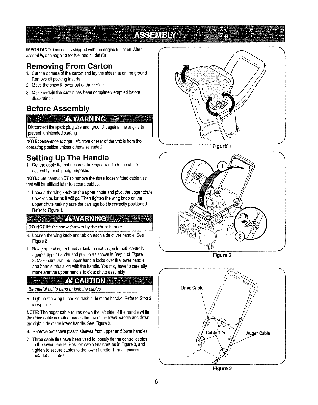
Setting Up The Handle
1_Cutthecabletiethatsecurestheupperhandleto thechute
assemblyfor shippingpurposes
NOTE: BecarefuINOTto removethe threelooselyfittedcableties
thatwill beutilizedlaterto securecables
2. Loosenthewingknobonthe upperchuteandpivotthe upperchute
upwardsasfaras itwiltgo_Thentightenthewingknobonthe
upperchutemakingsurethecarriageboltiscorrectlypositioned.
Referto Figure1.
DO NOTlift the snowthrowerby the chutehandle
3 Loosenthewingknobandtabon eachsideof thehandle.See
Figure2
4. Beingcarefulnotto bendorkinkthecables,holdbothcontrols
againstupperhandleandpullupasshowninStept of Figure
2. Makesurethatthe upperhandlelocksoverthe lowerhandle
andhandletabsalignwiththe handle.Youmayhavetocarefully
maneuvertheupperhandletoclearchuteassembly.
Becarefulnotto bendorkinkthecables.
5. Tightenthewingknobsoneachsideof thehandleRefertoStep2
in Figure2
NOTE:The augercableroutesclowntheleft sideofthehandlewhile
thedrivecableis routedacrossthetop ofthelowerhandleanddown
therightsideof thelowerhandleSeeFigure3
6 Removeprotectiveplasticsleevesfromupperandlowerhandles.
7 Threecabletieshavebeenusedtolooselytiethecontrolcables
to the lowerhandle..Positioncabletiesnow,as in Figure3, and
tightento securecablesto thelowerhandle.Trimoff excess
materialofcableties.
f
f
Figure i
Figure 2
Drive Cable
er Cable
Figure 3
J
J
/
/
/
\
Position
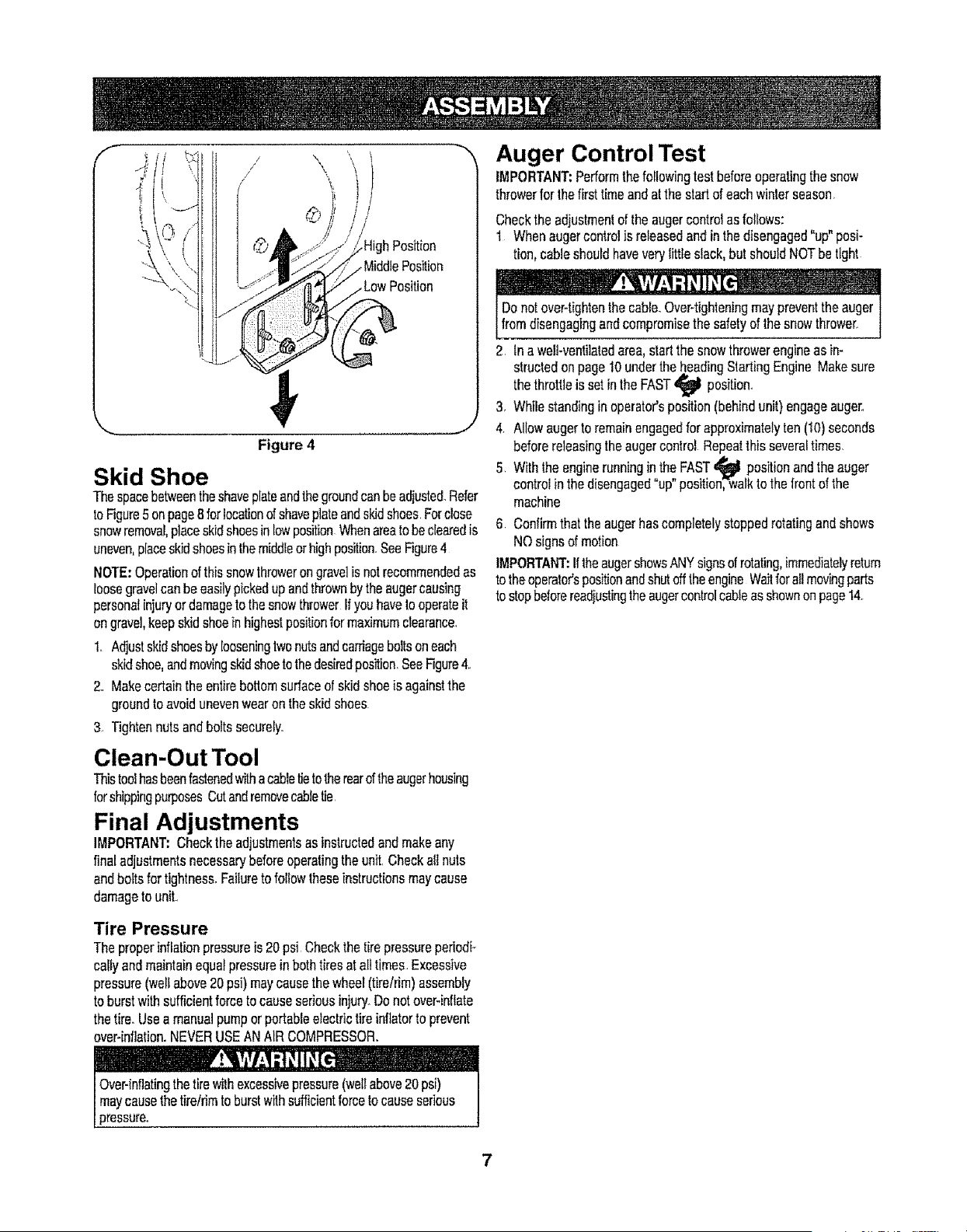
Figure 4
Skid Shoe
Thespacebetweentheshaveplateandthegroundcanbeadjusted.Refer
toFigure5onpage8forlocationofshaveplateandskidshoes.Forclose
snowremoval,placeskidshoesin lowpositionWhenareatobeclearedis
uneven,placeskidshoesinthemiddleorhighposition_SeeFigure4
NOTE:Operationof thissnowthroweron gravelisnotrecommendedas
loosegravelcanbeeasilypickedup andthrownbytheaugercausing
personalinjuryordamagetothesnowthrowerIfyouhavetooperateit
ongravel,keepskidshoein highestpositionfor maximumclearance.
1. Adjustskidshoesby looseningtwonutsandcaniageboltsoneach
skidshoe,andmovingskidshoetothedesiredposition,SeeFigure4.
2. Makecertaintheentirebottomsurfaceof skidshoeis againstthe
groundtoavoidunevenwearontheskidshoes
3 Tightennutsandboltssecurely.
Clean-Out Tool
Thistoolhasbeenfastenedwithacabletietotherearoftheaugerhousing
forshippingpurposesCutandremovecabletie
Final Adjustments
IMPORTANT:Checktheadjustmentsasinstructedandmakeany
finaladjustmentsnecessarybeforeoperatingtheunffCheckallnuts
andboltsfortightness.Failureto followlheseinstructionsmaycause
damagetounit..
Tire Pressure
Theproperinflationpressureis 20psi Checkthetirepressureperiodi-
rally andmaintainequalpressureinbothtiresat alltimes.Excessive
pressure(wellabove20psi)maycausethewheel(tire/rim)assembly
to burstwithsufficientforceto causeseriousinjury..Donotover-inflate
thetire.Useamanualpumporportableelectrictireinflatortoprevent
over-inflation.NEVERUSEANAIR COMPRESSOR.
Auger Control Test
IMPORTANT:Performthefollowingtestbeforeoperatingthesnow
throwerforthefirsttimeandatthestartof eachwinterseason.
Checktheadjustmentof theaugercontrolasfollows:
I Whenaugercontrolis releasedand in thedisengaged"up"posi-
tion,cableshouldhaveverylittle slack,but shouldNOTbetight
Donotover4ightenthecable.Over-tighteningmaypreventtheauger
fromdisengagingandcompromisethe safetyof thesnowthrower.
2 In a well-ventilatedarea,startthesnowthrowerengineasin-
structedonpage10undertheheadingStartingEngineMakesure
thethrottleis setin the FAST position..
3. Whilestandinginoperator'sposition(behindunit)engageauger.
4. Allowaugerto remainengagedforapproximatelyten (10)seconds
beforereleasingtheaugercontrol Repeatthis severa!times
5 Withthe enginerunninginthe FAST_ positionandtheauger
controlinthedisengaged"up"pesitionTwalktothefrontof the
machine
6 Confirmthattheaugerhascompletelystoppedrotatingandshows
NOsignsofmotion
IMPORTANT:IftheaugershowsANYsignsofrotating,immediatelyreturn
to theoperatorspositionandshutofftheengineWaitforatlmovingparis
to stopbeforereadiustingtheaugercontrolrableas shownonpage14.
7
f
Drive
Control
SkidShoe
Figure 5
BefamiliarwithallthecontrolsonthesnowthrowerandtheirproperoperationKnowhowIDstopthe machineand disengagethemquickly
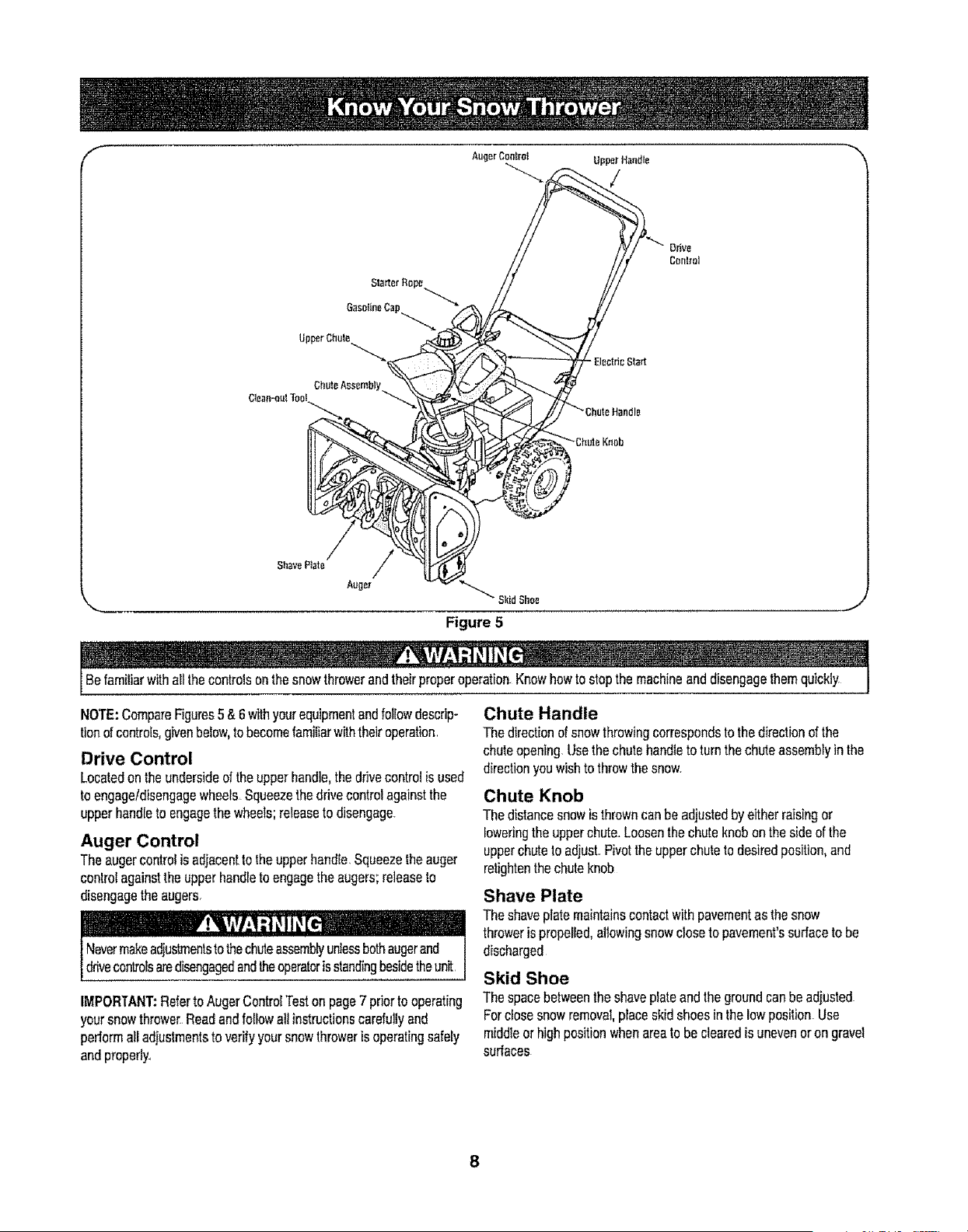
NOTE:CompareFigures5 &6 withyourequipmentandfollowdescrip-
tionofcontrols,givenbelow,tobecomefamiliarwiththeiroperation
Drive Control
Locatedontheundersideoftheupperhandle,thedrivecontrolis used
to engageldisengagewheels Squeezethedrivecontrolagainstthe
upperhandletDengagethewheels;releasetodisengage.
Auger Control
Theaugercontrolis adjacenttotheupperhandle.Squeezetheauger
conlrolagainsttheupperhandleto engagetheaugers;releaseto
disengagetheaugers.
IMPORTANT:RefertoAugerContrD!Teston page7 priorto operating
yoursnowthrDwe_Readandfollowall instructionscarefullyand
performalladjustmentstoverifyyoursnowthroweris operatingsafely
andpropedy_
Chute Handle
Thedirectionof snowthrowingcorrespDndsto thedirectionofthe
chuteopening.Usethechutehandleto turnthechuteassembtyin the
directionyouwishto throwthesnow.
Chute Knob
Thedistancesnowis throwncanbe adjustedbyeitherraisingor
[Dwedngthe upperchute.Loosenthe chuteknobon thesideofthe
upperchutetoadjust.Pivotthe upperchutetDdesiredposition,and
retightenthechuteknob
Shave Plate
Theshaveplatemaintainscontactwith pavementas thesnow
throweris propelled,allowingsnowcloseto pavement'ssurfaceto be
discharged
Skid Shoe
Thespacebetweentheshaveplateand thegroundcanbe adjusted
Forclosesnowremoval,placeskidshoesin thelowposition.Use
middleorhighpositionwhenareatobeclearedisunevenor ongravel
surfaces
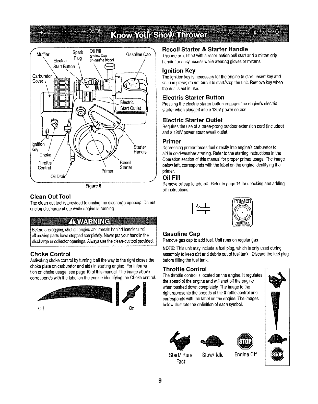
Choke
Threttie / Recoit
Control Primer Starter
OilDrain
Figure6
Starter
Handle
Clean Out Tool
Thecleanouttool isprovidedto unclogthedischargeopening.Donot
unclogdischargechutewh{leengineisrunning
Beforeunclogging,shutoffengineandremainbehindhandlesuntil
allmovingpartshavestoppedcompletelyNeverputyourhandinthe
dschargeorcolectoropenings.Alwaysusetheclean-outtoolprovided..
Choke Control
Activatingchokecontrolby turningitallthewayto therightclosesthe
chokeplateon carburetorandaidsin startingengine.Forinforma-
tiononchokeusage,seepage 10ofthis manual..Theimageabove
correspondswiththelabelontheengineidentifyingtheChokecontrol
Off On
Recoil Starter & Starter Handle
Thismotoris fittedwith a recoilactionpullstartanda mittengrip
handleforeasyaccesswhileweadngglovesor mittens
Ignition Key
Theignitionkeyisnecessaryforthe engineto start Insertkeyand
snapin place;donotturnitto start/stopthe unit.Removekeywhen
theunitis notin use.
Electric Starter Button
Pressingtheelectricstarterbuttonengagestheengine'setectric
starterwhenpluggedintoa 120Vpowersource.
Electric Starter Outlet
Requirestheuseofa three-prongoutdoorextensioncord(included)
anda 120Vpowersource/walloutlet
Primer
Depressingprimerforcesfueldirectlyintoengine'scarburetorto
aidincold-weatherstarting.Referto thestartinginstructionsin the
Operationsectionofthis manualfor properprimerusageTheimage
belowleft,correspondswiththelabelon theengineidentifyingthe
primer..
Oil Fill
Removeoilcaptoaddoil Referto page14forcheckingandadding
0ilinstructions.
Gasoline Cap
Removegascaptoadd fuel.Unitrunsonregulargas.
NOTE:Thisunitmayincludea fuelplug,whichis onlyusedduring
assemblyto keepdirt anddebrisoutoffueltank Discardthefuelplug
beforefillingthefueltank.
Throttle Control
Thethrottlecontrolis locatedonthe engineitregulates
thespeedofthe engineandwiflshutofftheengine
whenpusheddowncompletelyThe imageto the
rightrepresentsthe speedsof thethrottlecontroland
correspondswiththelabelontheengine Theimages
belowillustratethedefinitionof eachsymbol
Start/Run/ Slow/Idle Engine Off
Fast
Before Starting Engine
Engine Oil
Theengineisshippedwithoilin it.Checktheo11levefbeforefirstuse.
Forsubsequenl_Fups,usethegradeof engineoilspecifiedonpage
14.Toaddoil:
1. Removethedipstickfromtheoil fill.,Pourfreshoil slowlythrough
theplug,Replacedipstick
2 Checkandmakesurethat thelevelof oil is up tothe FULLmarkon
thedipstick.
Gasoline
Gasolineisflammableandcautionmustbeusedwhenhandling
I orsloringit, Donotfillfueltankwhitethesnowthroweris running,
[whenit ishotorwhenitis in an enclosedarea.
! - ,
I o anel trica I
L_moke duringfuek'ng I
1, Neverfill thefueltankcompletely.Fillthetankto nomorethan 112
inchbeJowbottomoffillerneckto providespaceforexpansionoffuel
NOTE:Thisunitmayincludea fuetplug,whichis onlyusedduring
assemblyto keepdirt anddebrisoutoffueltanK,Discardthefuelplug
beforefillingthefueltank,
2, Alwaysuseclean,fresh,unleadedgradeautomotivegasolineFill
thefueltankoutdoorsanduseafunnelor spoutto preventspilling
Makesurethatthecontainerfromwhichyoupourthegasolineis
cleanandfreefromrustorotherforeignparticlesMakesureto
wipeoffanyspilledfuelbeforestartingtheengine,
3 At theendof thejob,emptythefueltankif thesnowthroweris not
goingto beusedfor30daysorlongerStoregasolinein aclean
containerandkeepthecapinplaceon thecontainer,
Neveruseengineorcarburetorcleanerproductsin thefueltank,
Starting Engine
line!! A ._ _L _ .... -
Besureno oneotherthantheoperatorisstandingnearthesnow
throwerwhilestartingor operating°Donotoperatethissnowthrower
unassthechuteassemblyhasbeenproperlyinstalledandis secured
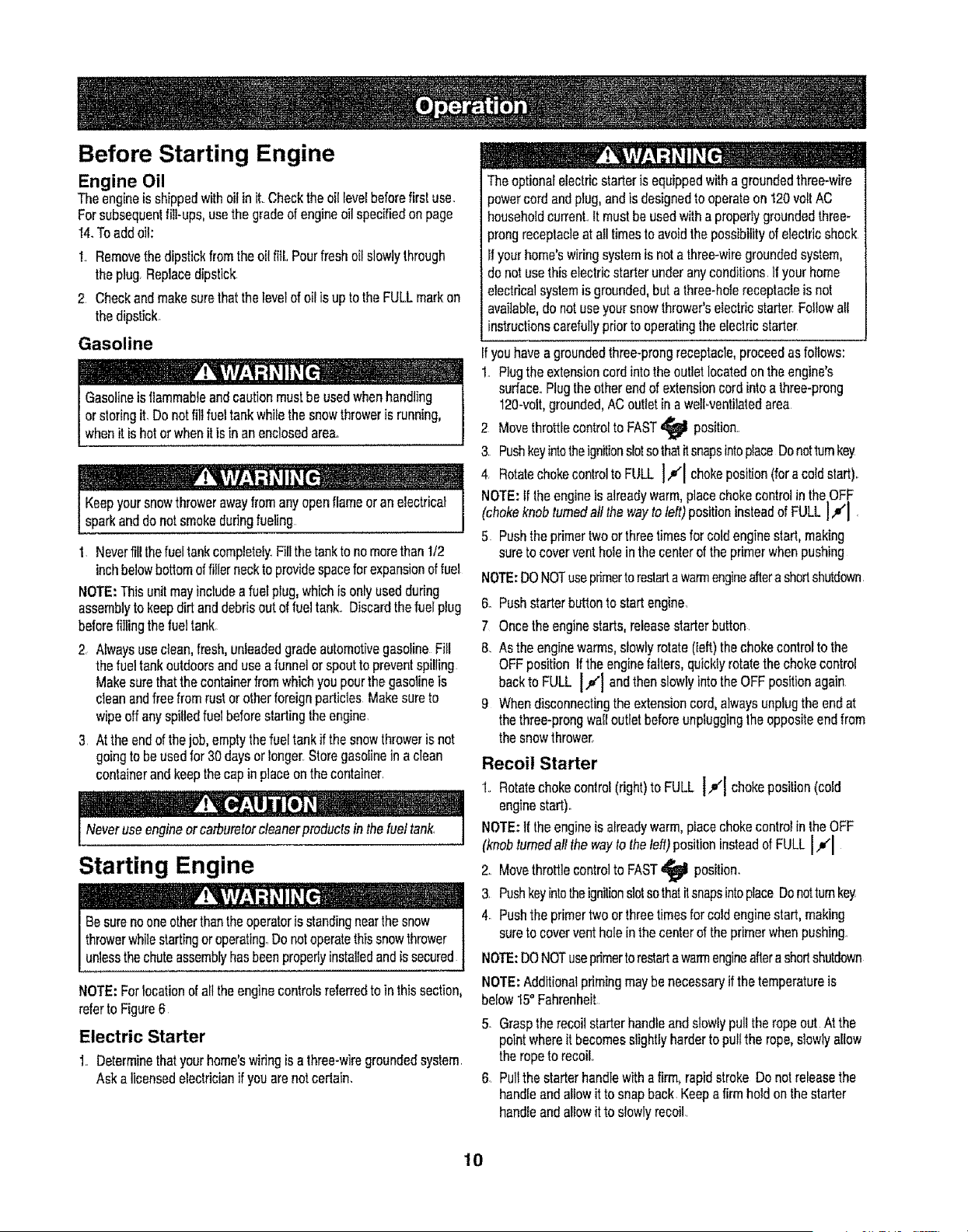
NOTE:Forlocationof all theenginecontrolsreferredto inthissection,
referto Figure6
Electric Starter
1,, Determinethatyourhome'swidngisa three-wiregroundedsystem,
Aska I]censedelecfdcianif youarenotcertain.
Theoptionalelectricstarteris equippedwithagroundedthree-wire
_ewercordandplug,andis designedtooperateon 120volt AC
householdcurrenLItmustbe usedwithaproperlygroundedthree_
prongreceptacleat alltimestoavoidthe possibilityof electricshock
Ifyourhome'swiringsystemis notathree-wiregroundedsystem,
donotusethis electricstarterunderanyconditions,Ifyourhome
electricalsystemisgrounded,buta three-holereceptacleisnot
available,do notuseyoursnowthrower'selectricstarter Followall
instructionscarefullypriortooperatingthe electricstartez
youhavea groundedthree-prongreceptacle,proceedasfollows:
1.,Plugthe extensioncordintotheoutletlocatedon theengine's
surface,,Plugtheotherendof extensioncordintoathree-prong
120-volt,grounded,ACoutletin a welFventilaledarea
2 Movethrottlecontrolto FAST
position_
3, PushkeyintotheignitionslotsothatitsnapsintoplaceDonottumkey
4, RotatechokecontroltoFULL ],_1 chokeposition(fora colctStart)r.
NOTE:If theengineis alreadywarm,placechokecontrolin the OFF
(chokeknobturnedall the wayto left)positioninsteadof FULL!,#'1 ,
5 Pushtheprimertwoor threetimesfor coldenginestart,making
sureto coverventhole inthe centerof theprimerwhenpushing
NOTE:DONOTusepdmertorestartawarmengineaftera shortshutdown
6, Pushstarterbuttonto startengine.
7 Oncetheenginestarts,releasestarterbutton
8. Asthe enginewarms,slowlyrotate(left)thechokecontroltothe
OFFpositionIfthe enginefalters,quicklyrotatethechokecontrol
backto FLILLI.,#1 andthenslowlyintothe OFFpositionagain
9 Whendisconnectingthe extensioncord,alwaysunplugthe endat
thethree-prongwalloutletbeforeunpluggingthe oppositeendfrom
thesnowthrower,
Recoil Starter
1,, Rotatechokecontrol(right)to FULL l.#l chokeposition(cold
enginestart)°
NOTE:{f theengineis alreadywarm,placechokecontrolinthe OFF
(knobturnedaftthe wayto theleft)positioninsteadof FULL IJ(I
2., Movethrottlecontrolto FAST
position,
3, PushkeyintotheignitionslotsothatitsnapsintoplaceDonottumkey
4_ Pushthe primertwo or threetimesforcoldenginestart,making
sureto coverventholein thecenterof theprimerwhenpushing,
NOTE:DONOTuseprimertorestartawamlengineafterashortshutdown
NOTE:Additionalprimingmaybe necessaryif the temperatureis
below15° Fahrenheit
5. Grasptherecoilstarterhandleandslowlypullthe ropeout Atthe
pointwhereit becomesslightlyharderto pullthe rope,slowlyallow
the ropeto recoil,,
6 Pullthe starterhandlewith a firm,rapidstroke Do notreleasethe
handleandallowitto snapback,Keepa firmhold on thestarter
handleandallowitto slowlyrecoil,,
10
7, Asthe enginewarms,slowlyrotate(left)thechokecontrolto the
OFFpositionif the enginefalters,quicklyrotatethechokecontrol
backto the FULL IJl positionandthenslowlyintotheOFF
positionagain
NOTE:Allowthe engineto warmupfor a fewminutesafterstarting
Theenginewill notdevelopfull poweruntilit reachesoperating
temperatures,
Before Stopping
1..Runenginefora fewminutestohelpdryoff anymoistureon engine
2 Toavoidpossiblefreeze-upof thestarter,followthesesteps:
Recoil Starter
a Withthe enginerunning,pullthe starterropewitha rapid,
continuousfull armstrokethreeorfourtimes
To Stop The Snow Thrower
1. Tostopthe wheels,releasethedrivecontrol.
2 Tostopthrowingsnow,releasetheaugercontrol.
3. Toslopengine,pushthrottlecontrolleverto OFF _ andpullout
thekey Do notturnkey
........................... ,i
Thetemperatureof mufflerandthesurroundingareas y
t50° EAvoidtheseareas
Clearing The Snow
CAUTION:Checktheareato beclearedforforeignobjects_Remove
foreignobjects,ifany
1 Startthe enginefollowingstartinginstructions.
2 Allowthe enginetowarmupfor afewminutesasthe enginewill
notdevelopfull poweruntilit reachesoperatingtemperature.
3. Rotatethechuteassemblyto thedesireddirection,awayfrom
bystandersand/orbuildings
4 Makingcertainnobystandersor obstaclesareinfrontof theunit,
squeezethe augercontrolcompieletyagainsttheupperhandleto
fullyengagetheaugers.
5 Whilethe augercontrolis engaged,squeezethe drivecontrol
completelyagainstthe upperhandletoengagethewheelsDonot
=feather"theddveconlrol_
6 Asthesnowthrowerstartsto move,maintainafirmholdonthe
handle,andguidethe snowthroweralongthepathto be cleared
7 Releasetheaugeranddrivecontrolstostopthe snowthrowing
actionandforwardmotion
NOTE:Yourunitis equippedwilha clutchinthetransmission..If the
wheelsstopturningwhiletryingto dischargelargevolumesofsnow,
immediatelydisengagethe drivecontrolandallowtherotatingaugers
to dischargesnowfromthehousing.Reducetheclearingwidthand
continueoperation.
8 On eachsucceedingpass,readjustthe chuteassemblyto the
desiredpositionandslightlyoverlapthepreviouslyclearedpath
Positioning Discharge Chute
Loosenthechuteknobandpivotupperchuteto desiredposition..Tighten
thechuteknobmakingsurethecarriageboltiscorrectlypositioned
Rotatechutehandletodesiredoperatingposition
Donot liftthesnowthroweratanytimebythechutehandle..
Operating Tips
1. Formostefficientsnowremoval,removesnowimmediatelyafteritfalls.
2.. DischargesnowdownwindwheneverpossibleSlightlyoverlap
eachpreviouspath
3 Settheskidshoes1/4"belowtheshaveplatefor normalusage
The skidshoesmaybeadjustedupwardforhard-packedsnow.
NOTE:it is netrecommendedthatyouoperatethissnowthroweron
gravelasloosegravelcanbe easilypickedup andthrownbythe auger
causingpersonalinjuryandtordamagetothesnowthrower
4 If for somereason,youhaveto operatethesnowthroweron gravel,
keepthe skidshoeinthe highestpositionfor maximumclearance
betweenthegroundandtheshaveplate.
5. Cfeanthesnowthrowerthoroughlyaftereachuse
Cleaning The Chute Assembly
The clean-outtoolis convenientlyfastenedtotheaugerhousingwitha
mountingclip,
Whensnowand icecollectinthechuteassemblyduringoperation,
usethis toolto safelycleanthechuteand chuteopening Followthe
stepsbelowtooperateit..
Stopengineby movingthrottleleverto stop_ positionandwaitfor
allmovingpartsto stopbeforeusingthe clean-outtool.
1 Releasebothaugerand drivecontrols
2 Stoplheengineby movingthrottleleverto stop_ position
3 Removetheclean-outtoolfromtheclipwhichsecuresit to the rear
ofthe augerhousing.
4. Usethe shovel-shapedendoftheclean-outtoolto dislodgeand
scoopanysnowandicewhichhasformedin andnearthe chute
assembly
Neveruseyourhandstocleansnowandicefromthechuteassembty1
I oraugerhousng_ 1
5 Re-fastentheclean-outtool,withthehandleon therightsideofthe
housing,to themountingcliponthe augerhousingYoucanstart
operatingyoursnowthrowernow
11
General Recommendations
I. Alwaysobservesafetyruleswhenperforminganymaintenance..
2. Thewarrantyonthissnowthrowerdoesnotcoveritemsthathave
beensubjectedto operatorabuseor negligenceToreceiveful_
valuefromthewarranty,operatormustmaintainthe snowthrower
as instructedinthismanual°
3. Periodicattycheckall fastenersandhardwareto makesurethese
aretight.
Beforeservicing,repairing,lubricatingorinspecting,disengageaI{controls
andstopengineWaituntilallmovingpartshavecometoacompletestop.
Disconnectsparkplugwkeand groundit againsttheengineto prevent
unintendedstartingAlwayswearsafetygiassesduringoperationor while
performinganyadiustmentsorrepair&
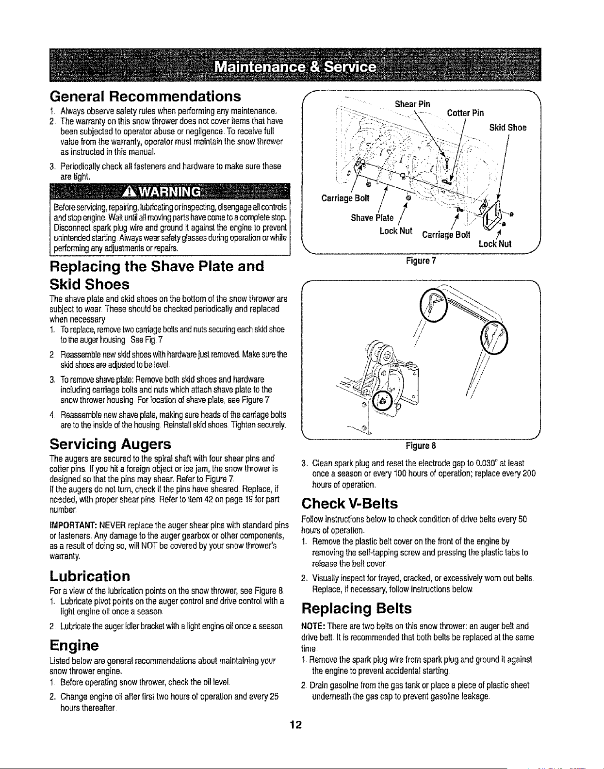
Replacing the Shave Plate and
Skid Shoes
Theshaveplateandskidshoesonthebottomofthe snowthrowerare
subjecttowear Theseshouldbecheckedperiodicallyand replaced
whennecessary
1..Toreplace,removetwocarriageboilsandnutssecuringeachskidshoe
tot,.heaugerhousingSeeFig 7
2 Reassemblenewskidshoeswithhardwarejustremoved.Makesurethe
skidshoesareadjustedtobelevel.
3. Toremoveshaveplate:Removebothskidshoesandhardware
includingcarriageboltsandnutswhichattachshaveplateto the
snowthrowerhousingFortocationofshaveplate,seeFigure7
4 Reassemblenewshaveplate,makingsureheadsofthecarriagebolts
aretotheinsideofthehousing.ReinstallskidshoesTightensecurely.
Servicing Augers
Theaugersaresecuredto thesplratshaftwithfourshearpinsand
cotterpinsIfyouhit aforeignobjectoricejam,thesnowthroweris
designedso thatthepinsmayshear.Referto Figure7
Iftheaugersdo notturn,checkif thepinshavesheared.Replace,if
needed,withpropershearpins Referto item42onpage19for part
number
IMPORTANT:NEVERreplacethe augershearpinswithstandardpins
or fastenersAnydamagetothe augergearboxorothercomponents,
as aresultof doingso,willNOTbecoveredbyyoursnowthrower's
warranty..
Lubrication
Foraviewofthe lubricationpointsonthe snowthrower,seeFigure8
t. Lubricatepivotpointson theaugercontrolanddrivecontrolwitha
lightengineoiloncea season.
2 Lubricatetheaugeridlerbracketwithalightengineoilonceaseason
Engine
Listedbelowaregeneralrecommendationsaboutmaintainingyour
snowthrowerengine.
I Beforeoperatingsnowthrower,checktheoil level
2. Changeengineoilafterfirsttwohoursof operationandevery25
hoursthereafter
Cotter Pin
Skid Shoe
Carriage Bolt
Shave Plate / /
LockNut Carriage Bolt
LockNut
Figure7
/
""-4
Figure8
3. Cleansparkplugandresettheelectrodegapto O.r030nat least
onceaseasonor every100hoursof operation;replaceevery200
hoursof operation.
Check V-Belts
FoIlowinstructionsbelowtochockconditionofdrivebeltsevery50
hoursofoperation.
1. Removethe plasticbeltcoveronthe frontof the engineby
removingthe self-tappingscrewandpressingtheplastictabsto
releasethebeltcove[
2. Visuallyinspectfor frayed,cracked,orexcessivelywornoutbelts.
Replace,if necessary,followinstructionsbelow
Replacing Belts
NOTE:Therearetwobeltsonthissnowthrower:anaugerbo!land
drivebelt It is recommendedthatbothbeltsbe replacedat thesame
time
1.Removethesparkplugwirefromsparkplugandgroundit against
theengineto preventaccidentalstarting
2 Draingasolinefromthegastankor placea pieceof plasticsheet
underneaththegascapto preventgasolineleakage.
12
f
f
\
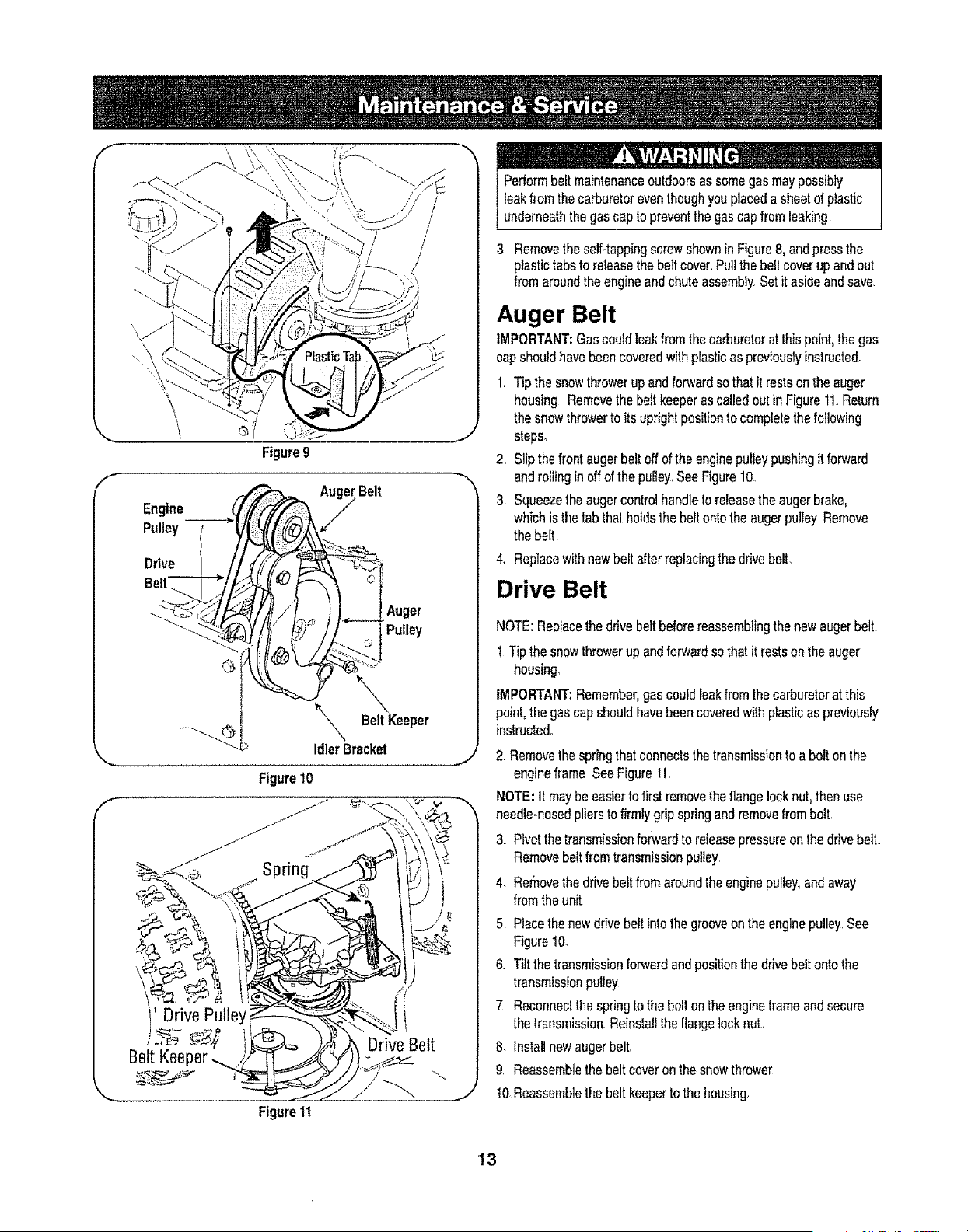
Engine
Pulley
Drive
Belt----T-_
Figure9
Belt
Auger
Pulley
_'X BeltKeeper
Idler Bracket
Figure10
Belt Keeper
Figure 11
J
J
J
! £ L_L L
Performbeltmaintenanceoutdoorsassomegasmaypossibly
leakfromthecarburetoreventhoughyouplaceda sheetofplastic
underneaththe gascapto preventthe gascapfromleaking.
3 Removetheself+tappingscrewshownin Figure8, andpressthe
plastictabsto releasethe beltcover+Pullthebeltcoverupandout
fromaroundthe engineandchuteassembly.Setit asideandsave+
Auger Belt
IMPORTANT:Gascouldleakfromthecarburetoratthispoint,thegas
capshouldhavebeencoveredwith plasticas previouslyinstructed.
1+Tipthesnowthrowerupandforwardsothatitrestson theauger
housing Removethe beltkeeperascalledoutin FigureI1+Return
thesnowthrowerto itsuprightpositionto completethe following
steps+
2. Slipthefrontaugerbeltoffofthe enginepulieypushingit forward
androllinginoffofthe pulley,See Figure10
3. Squeezetheaugercontrolhandleto releasetheaugerbrake,
whichisthetab thatholdsthebeltontothe augerpulley Remove
thebeit
4. Replacewithnewbeltafterreplacingthedrivebelt.
Drive Belt
NOTE:Replacethedrivebeltbeforereassemblingthe newaugerbelt
I Tipthesnowthrowerupandforwardsothatit restsonthe auger
housing.
IMPORTANT:Remember,gascouldleakfromthecarburetorat this
point,thegascapshouldhavebeencoveredwithplasticas previously
instructed+
2 Removethe springthatconnectsthetransmissionto a boltonthe
engineframe SeeFigure11.
NOTE:it maybe easiertofirstremovetheflangelocknut,thenuse
needle+nosedplierstofirmlygrip springandremovefromboll
3 Pivotthetransmissionforwardtoreleasepressureon thedrivebelt.
Removebeltfromtransmissionpu!tey.
4+ Removethedrivebeltfromaroundtheenginepulley,andaway
fromthe unit
5. Placethe newdrivebelt intothe grooveonthe enginepulley,See
Figure10.
6+ Tiltthetransmissionforwardandpositionthe drivebeltontothe
transmissionpulley
7 Reconnectthespringto the boltontheengineframeandsecure
thetransmissionReinstalltheflangelocknut..
8. Installnewaugerbeltr
9. Reassemblethe beltcoveronthesnowthrower
10Reassemblethebeltkeeperto thehousing.
13
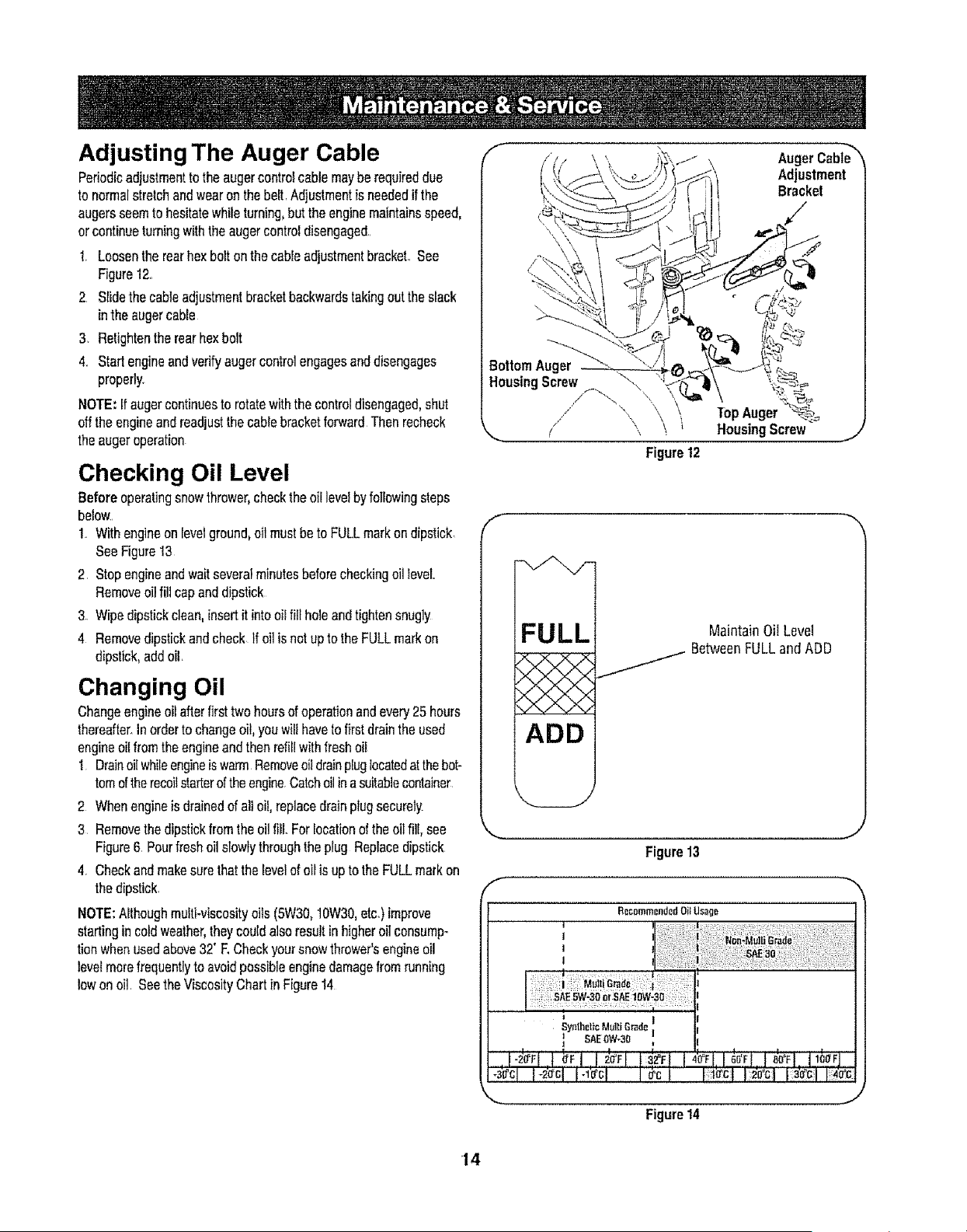
Adjusting The Auger Cable
Periodicadjustmenttotheaugercontrolcablemaybe requireddue
to normalstretchandwearon thebeR1Adjustmentis neededif the
augersseemto hesitatewhileturning,buttheenginemaintainsspeed,
orcontinueturningwiththe augercontroldisengaged..
1. Loosentherearhexboltonthe cableadjustmenlbracket.See
Figure12.
2 SIidethe cableadjustmentbracketbackwardstakingouttheslack
intheaugercable
3 Retightentherearhexbolt
4. Startengineandverifyaugercontrolengagesanddisengages
properly.
NOTE:If augercontinuesto rotatewiththecontroldisengaged,shut
offtheengineandreadjustthecablebracketforwardThenrecheck
theaugeroperation
Checking Oil Level
Beforeoperatingsnowthrower,checktheoil]evetbyfollowingsteps
below..
1. Withengineon levelground,oilmustbe toFULLmarkon dipstick
SeeFigure13
2. Stopengineandwaitseveralminutesbeforecheckingoillevel
Removeoilfill capanddipstick
3. Wipedipstickclean,insertitintooil fill holeandtightensnugly
4 Removedipstickandcheck If oil isnotupto theFULLmarkon
dipstick,addoil
Changing Oil
Changeengineoilafterfirsttwohoursofoperationandevery25 hours
thereafter.Inorderto changeoil,youwill havetofirstdraintheused
engineo1Ifromtheengineandthenrefillwithfreshoil
1 DrainoilwhileengineiswarmRemoveoii drainpluglocatedatthebot-
tomoftherecoilstarteroftheengine.Catchoilinasuitablecontainer
2 Whenengineisdrainedof elioil,replacedrainplugsecurety
3 RemovethedipstickfromtheoilIibLForiocationof theoilfill, see
Figure6. Pourfreshoil slowlythroughtheplug Replacedipstick
4. Checkandmakesurethat thelevelof oilis uptothe FULLmarkon
thedipstick.
NOTE:Althoughmulti-viscosityoils (5W30,10W30,etc.)improve
startingincoldweather,theycouldalsoresultinhigheroilconsump-
tionwhenusedabove32' E Checkyoursnowthrower'sengineoil
levelmorefrequentlyto avoidpossibleenginedamagefromrunning
lowon oil. SeetheViscosityChartin FigureI4
F
Auger Cabie_
Adjustment
Bracket
HousingScrew _\
\
\
Figure12
TopAuger _=
HousingScrew
FULL
ADD
MaintainOil Level
_ BetweenFULLandADD
Figure 13
I
I
I
I
R_commcndcdOiLU_g_
Sy_thelicMultiSr_d_ ]
SAE0W-30
J
Figure14
'14
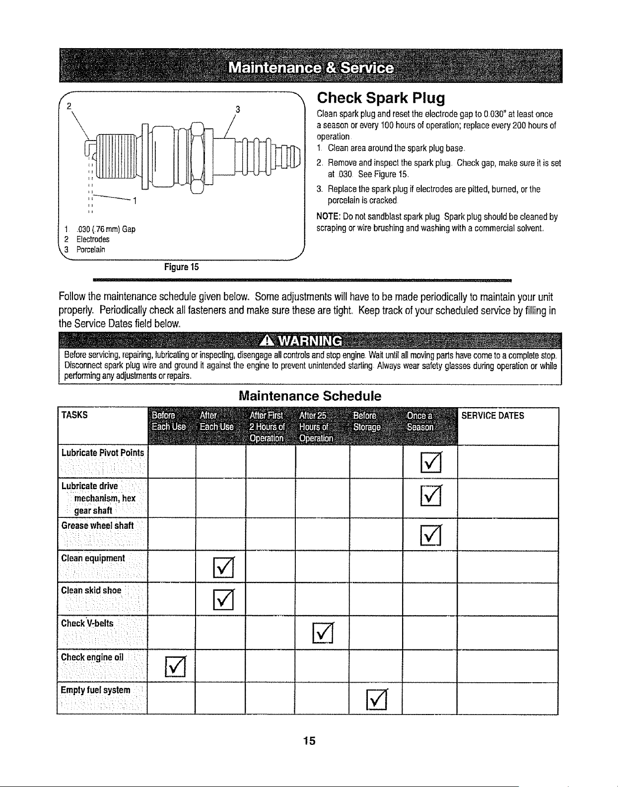
1 _030(76 ram)Gap
2 Electrodes
3 Porcelain
Figure15
Check Spark Plug
Cleansparkplugandresettheelectrodegap to 0030"at leastonce
a seasonor every100hoursof operation;replaceevery200hoursof
operation
1 Cleanareaaroundthesparkpiugbase,
2. Removeandinspectthe sparkplug. Checkgap,makesureitisset
at 030 SeeFiguret5,
3. Replacethe sparkplugff electrodesare pitted,burned,orthe
porcelainiscracked
NOTE:Donotsandblastsparkplug Sparkplugshouldbe cleanedby
scrapingorwirebrushingandwashingwitha commercialsolvent.
Followthe maintenanceschedulegiven below°Someadjustmentswillhavetobe madeperiodicallyto maintainyoiJrunit
properly_Periodicallycheckall fastenersandmakesure theseare tighL Keeptrack of your scheduledserviceby fillingin
theService Datesfield below.
performinganyadjustmentsorrepairs_
TASKS
LubricatePivot Points
Maintenance Schedule
Lubricatedrive
mechanism,hex
gearshaft
Greasewheelshaft
Cleanequipment
Cleanskidshoe r_
i- i
CheckV-belts |
Checkengineoil
Emptyfuelsystem
SERVICE DATES
15
Ifthesnowthrowerwil!notbeusedfor 30 daysor longer,or if it is theendofthe snowseasonwhenthelastpossibilityofsnowisgone,the
equipmentneedsto bestoredproperlyFollowstorageinstructionsbelowtoensuretopperformancefromthe snowthrowerfor manymoreyears.
PREPARING ENGINE
Short-Term Storage
Itisimportantto preventgumdepositsfromforminginessentialfuei
systempartsof the enginesuchasthecarburetor,fuelfilter,fuelhose,
ortankdudngshort-termstorage(I5-30days) Topreventthis,treat
thefuel systemusinga fuelstabilize_.
Fuelstabilizer(suchas STA-BtLTM or ULTRA-FRESHTM) is anaccept-
ablealternativein minimizingtheformationoffuel gumdepositsduring
storage.Addstabilizertogasolineinfueltankor storagecontainer
AlwaysIoltowmixratiofoundonstabilizercontainer.Runengineat
least10minutesafteraddingstabilizertoallowit toreachthecarbure-
tor.
[light as ona _eor gasappliance, j
PREPARING SNOW THROWER
• Whenstoringthesnowthrowerin anunventilatedor metalstor-
ageshed,careshouldbe takento rustproofthe equipment.Using
alightoilorsilicone,coattheequipment,especiallyanychains,
springs,bearingsandcables.
• Removeairdirtfromexteriorofengineand equipment.
• Followlubricationrecommendations
• Storeequipment[na clean,dryarea
Alcoholblendedfueis(calledgasoholorusingethanolormethanol)
canattractmoisturewhichleadstoseparationandformationof acids
duringstorage..Acidicgascandamagethe fuelsystemofan engine
whileinstorage°
Long-Term Storage
Toavoidengineproblems,thefuelsystemshouldbe emptiedbefore
storagefor30daysorlonger.
Fuelleftin engineduringwarmweatherdeterioratesandwillcause
I seriousstartingproblems, j
1_Runthe engineuntilthe fueltank isemptyanditstopsdueto lack
offuel.Donotattempttopourfuelfromtheengine
I__Im'!_,V_TI,! _ _ i i_[ ' --
I Neveruseengineor cteaningproducts or !
carburetor inthefueltank
damagemayoccur j
2. Removethesparkplugandpourone(1)ounceofengineoil
throughthesparkplugholeintothecylinder:Coversparkplughole
witha ragand cranktheengineseveraltimesto distributethe oil
Replacesparkplug.,
16
Beforeperforminganytypeof maintenance/service,disengageall
controlsandstoptheengine,Waituntilall movingpartshavecometo I
acompletestop Disconnectsparkplugwireandgroundit againstthe I
enginetopreventunintendedstartingAlwayswearsafetygfassesdudngI
1operationor whileperforminganyadjustmentsorrepairs_ ,,I
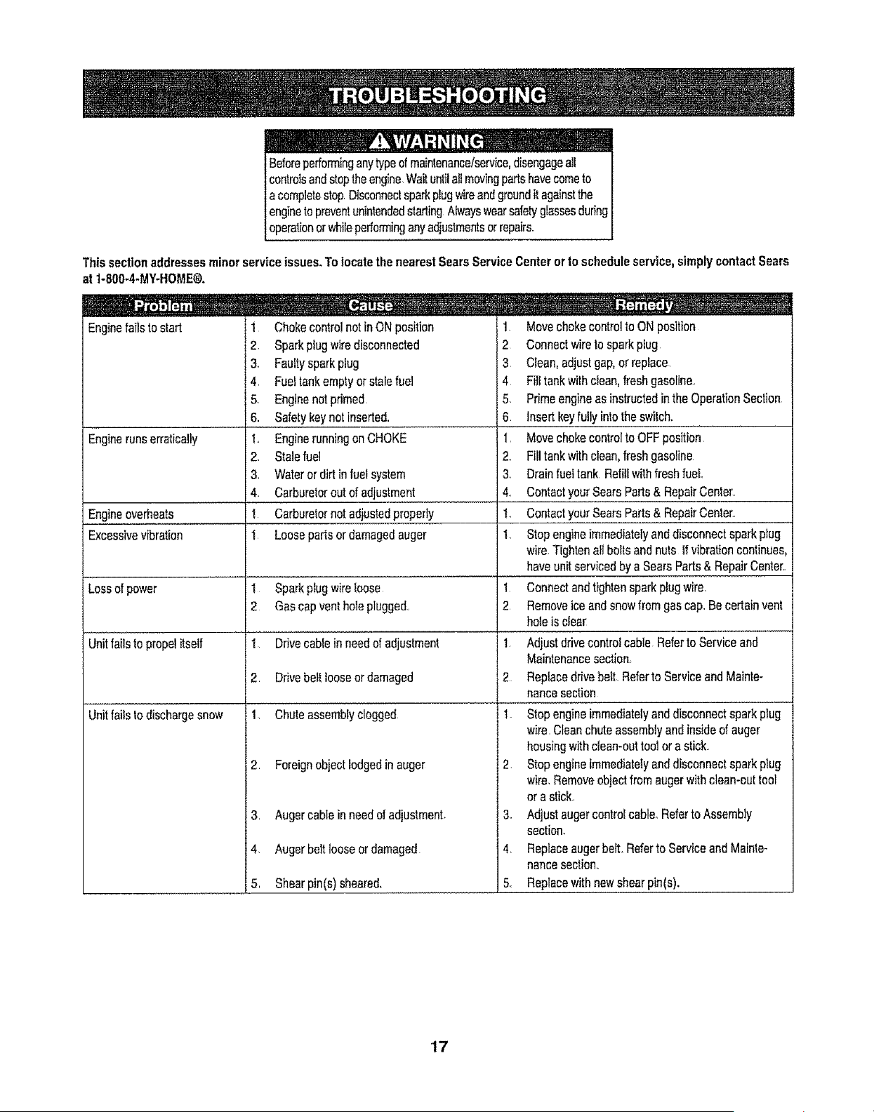
This section addressesminor service issues.To locatethenearestSearsService Centeror to scheduleservice,simply contactSears
at1-800-4-MY-HOME®.
1 ChokecontrolnotinONposition
2 Sparkplugwiredisconnected
3, Faultysparkplug
4, Fueltankemptyorstalefuel
5 Enginenotprimed
6. Safetykeynotinserted.
1., Enginerunningon CHOKE
2. Stalefuel
3. Waterordirt infuelsystem
4. Carburetoroutof adjus!me,n!.................................
I Carburetornotadjustedproperly
1 Loosepartsor damagedauger
Sparkplugwireloose
2 Gascapventholeplugged.
Enginefailsto start
Enginerunserratically
Engineoverheats
Excessivevibration
Lessof power
1
Unitfallstopropelitself
Unitfailstodischargesnow
1 Drivecableinneedof adjustment
2 Drivebelttooseor damaged
1 Chuteassemblyclogged
2 Foreignobjectlodgedin auger
3 Augercableinneedofadjustmant.
4, Augerbeltlooseordamaged
5, Shearpin(s)sheared.
1 Movechokecontrolto ONposition
2 Connectwireto sparkpiug
3 Clean,adjustgap,orreplace
4 Fill tankwithclean,freshgasofine.,
5. Primeengineas instructedin theOperationSection
6, Insertkeyfullyintotheswitch,
1, Movechokecontro]to OFFposition
2,, Fill tankwithclean,freshgasoline
3_ Drainfueftank Refitlwithfreshfuel
4., ContactyourSearsParts& RepairCenter.,
I, Con!actyou!,,S,ea,!,s,,,,Parts&RepairCenter,
1, Stopengineimmediatelyanddisconnectsparkplug
wire.Tightenallboltsandnuts ifvibrationcontinues,
haveunitservicedby a SearsParts&RepairCenter,,
1 Connectandtightensparkplugwire.
2 Removeiceand snowfromgascap,,Be certainvent
holeisclear
t Adjustdrivecontrolcable Referto Serviceand
Maintenancesection_
2 Replacedrivebelt.RefertoServiceandMainte-
nancesection
1. Stopengineimmediatelyanddisconnectsparkplug
wire,Cleanchuteassemblyand insideof auger
housingwithclean-outtool ora stick,
2 Stopengineimmediatelyanddisconnectsparkplug
wire.Removeobjectfromaugerwithclean-outtool
or a stick..
3. Adjustaugercontrolcable.Referto Assembly
section.
4. Replaceaugerbelt,,Referto ServiceandMainte-
nancesection,.
5. Replacewithnewshearpin(s).
17
REF PART ...._ : DESCRIPTION Qty,
NO. NUMBER
1 684-04037 Chute Assembly 1
2 710-04071 Carriage Bolt 511648 x 1.0" 1
3 710-0451 Carriage Bolt 5/t6-18 11
4 710-0260A Carriage Bait 5II648 x .62 4
5 720-0284 Wing Knob 5t16-18 1
6 731-04388A Chute Handle 1
7 731-04426A Upper Chute 1
8 736-0267 Rat Washer .385 x ,87 x ,06 1
REF PART DESCRIPTION Qty.
NO. NUMBER ........... : : : : _ _ I
25 731-042!8B Impeller 1
, ,. ,, ,,,, ,,,...................
26 732_0611 Extension Spdng I
27 736-0174 Wave Washer t
28 738-0281 Shoulder Screw 318-16 1
29 741-0245 Hex Fiange Bearing 2
30 741-0309 Ball Bearing 1
3t 750-04191 Spacer 1
32 741-0919 Rat ld}er 1
9 731-04127 Lower Chute 1
10 73!:043 3..............ChuteRing 1
11 731-2636A Chute Adapter 5" Dia. 1
12 732-041tt Chute Adjustment Spring 1
13 712-04064 Range Lock Nut 114-20 5
33 784-0434 Auger Idler Bracket
34 790-00075 Bearing Housing
35 618-04292A Auger Gearbox Assembty
36 684-04!13A ':Auger Assembly- LH
37 684-04114A ; Auger Assembly- RH
1
1
t
2
2
14 731-2643 Clean-out Tool 1
15 731-2635 Clean-out Tool Mount 1
16 725-0t57 Cable Tie 1
17 710-0134 Carriage Screw 1/4-20 x 0,62" 5
18 710-0520 Hex Bolt 318-16x 1.50" 1
38 684-04166A Auger Housing. 22" t
39 714-04040 Bow Tie Cotter Pin 72 4
40 731-04870 Spacer, 1.25 x.75 x 1.00 4
41 736-0351 _,Rat Washer 2
42 738-04124A Shear Pin,.25 x 1,50 4
19 7t0-04484 AB Screw 511648 x .750
20 7t2-04063 Range Lock Nut, 5/16-18
21 712-04065 Range Lock Nut, 3/8-t6
22 750-04852 ,Shou!der,Spacer.......................
23 715-04020 ...... Sp!,[,a,l,,p!n.......
24 726-04012 Push On Nut
4 43 741-0493A Range Bushing 8
10 44 790-00067A Hex Bearing Housing 2
2 45 790-00117 Shave Plate 2.25 x 21.66 LG 1
1 46 784-5580 Skid Shoe 2
2 ...... t71°°48°estud 1
2 I
19
@
20
Re[ No_ PartNo_ Description
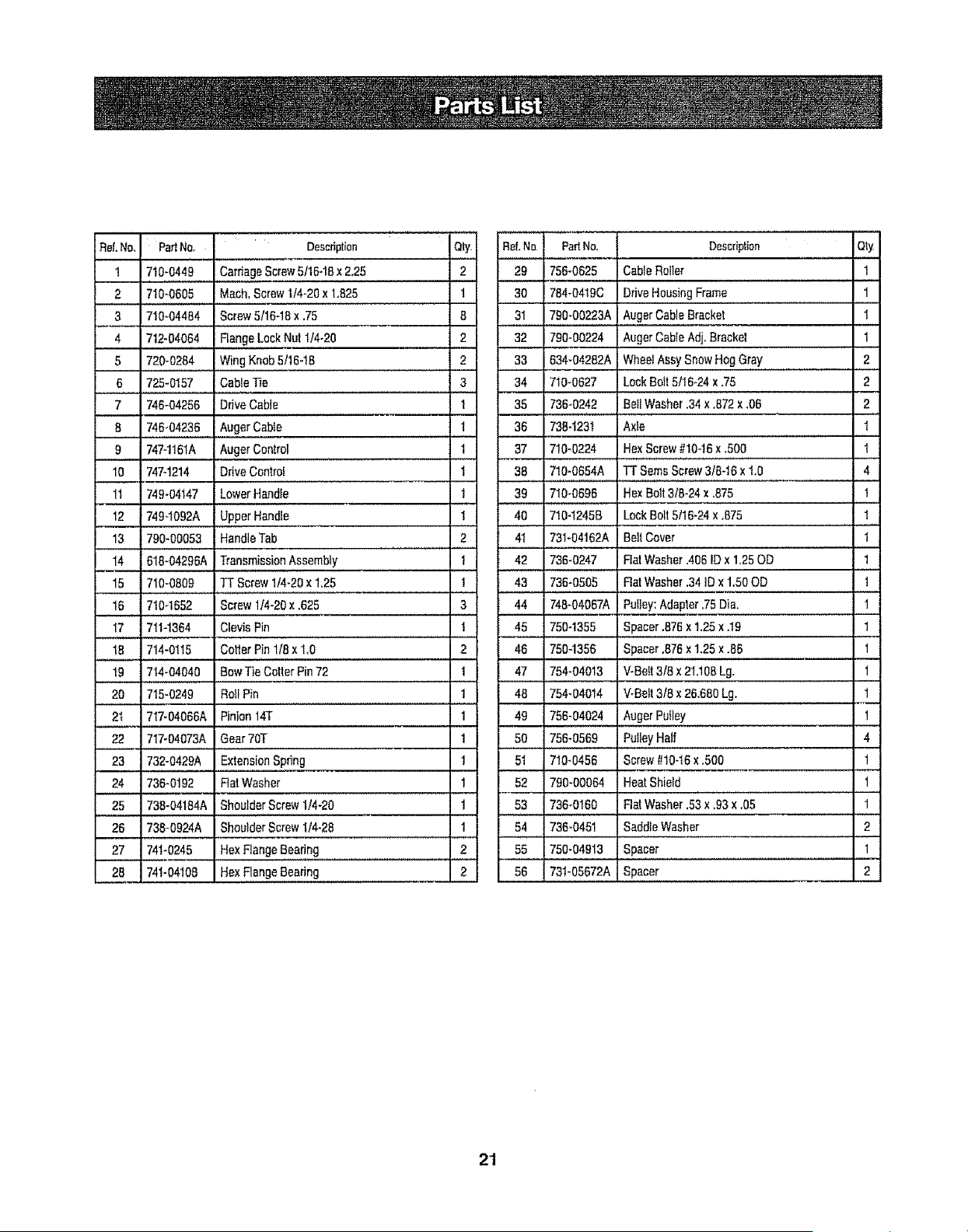
1 71o:044............Ca ageScrewS/18-1ax2.28
2 710-0605 Mach, Screw 1!4-20 x 1,825
3 710-04484
4 712-04064
5 720-0284
6........725-0157
7 746-04256
8 746_04236
.......9 747-1161A
Qty
2
1
iRef, No PaiNe.
29 756-0625
30 784-0419C
Screw 5116-t8 x .75 6
Flange Lock Nut 1/4-20 2
Wing Knob 5/16-18 2
Cable T_e 3
Auger Cable Bracket
Auger Cable Adj. Bracket
Wheel Assy Snow Hog Gray
Lock Bolt 5/16-24 x .75
35 736-0242 Boil Washer 34 x .872 x ,06
36 7384231 Axle
37 7t0-0224 Hex Screw #10-16 x 300
m
Ddve Cable 1
Auger Cable 1
Auger Control t
31 790-00223A
32 790-00224
33 634-04282A
34 710-0627
Description Qty
Cable Roller 1
Drive HousingFrame 1
1
1
2
2
2
1
1
10 747-12t4 Drive Control
1t 749-04147 Lower Handle
12 7494092A Upper Handle
13 790-00053 Handle Tab
14 618-04296A Tran,sm,!ss,i,o,n,,Assembly
15 710-0809 TT Screw 1/4-20 x t.25
16 710-1652 Screw 1/4-20 x .625
17 711-1364 Clevis Pin
,, ,.., ,,,,,,,,,,,,.,
18 714-0115
t
t
1
• ,,,,
2
t
!
3
t
Cotter Pin 116x 1.0 2
38 710-0654A
39 710-0696
40 710-1245B
41 731-04162A
42 736-0247
43 736-0505
44 748-04067A
45 750-1355
46 7504356
TT Seres Screw 3/8-t6 x 1+0 4
Hex Bolt 318-24 x ,875
Lock Bolt 5118-24x ,875
BeI! Cover
Rat Washer .406 ID x 125 OD
Rat Washer .34 ID x 1.50 OD
Putley: Adapter .75 Dia,
Spacer .676 x 1.25 x .19
Spacer .876 x 1.25 x .86
1
1
1
1
1
1
1
1
19 714-04040 Bow Tie Cotter Pin 72 1
20 715-0249 Roll Pin 1
2t 717-04066A Pinion 14[ 1
22 717-04073A Gear 70T 1
23 732-0429A Extension Spring t
24 736-0192 Flat Washer 1
25 738-04184A Shoulder Screw 1/4-20 1
26 738-0924A Shoulder Screw 1/4-28 1
27 74t-0245 Hex Flange Bearing 2
28 7,t.04103HexF!an0eBea'ini I
47 754-04013 WBeft 3/8 x 21,108 Lg. 1
48 754-04014 V-Beft 3/8 x 26.660 Lg. 1
49 756-04024 Auger Putley 1
50 756-0569 P,oileyHalf 4
51 710-0456 Screw #10-t6 x .500 1
,, ,,,,
52 790-00064 Heat Shield 1
, 53 ,736-0160 , Rat Washer.53 x .93 x ,05 1
54 736-0451 Saddle Washer 2
55 750-04913 Spacer 1
56 731-05672A Spacer _ I 2
21
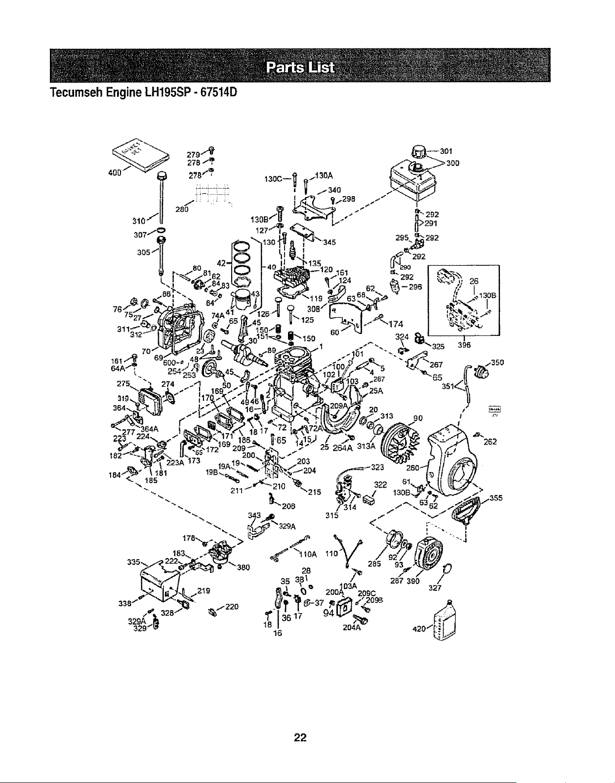
Tecumseh Engine LH195SP - 67514D
76-:
311
22
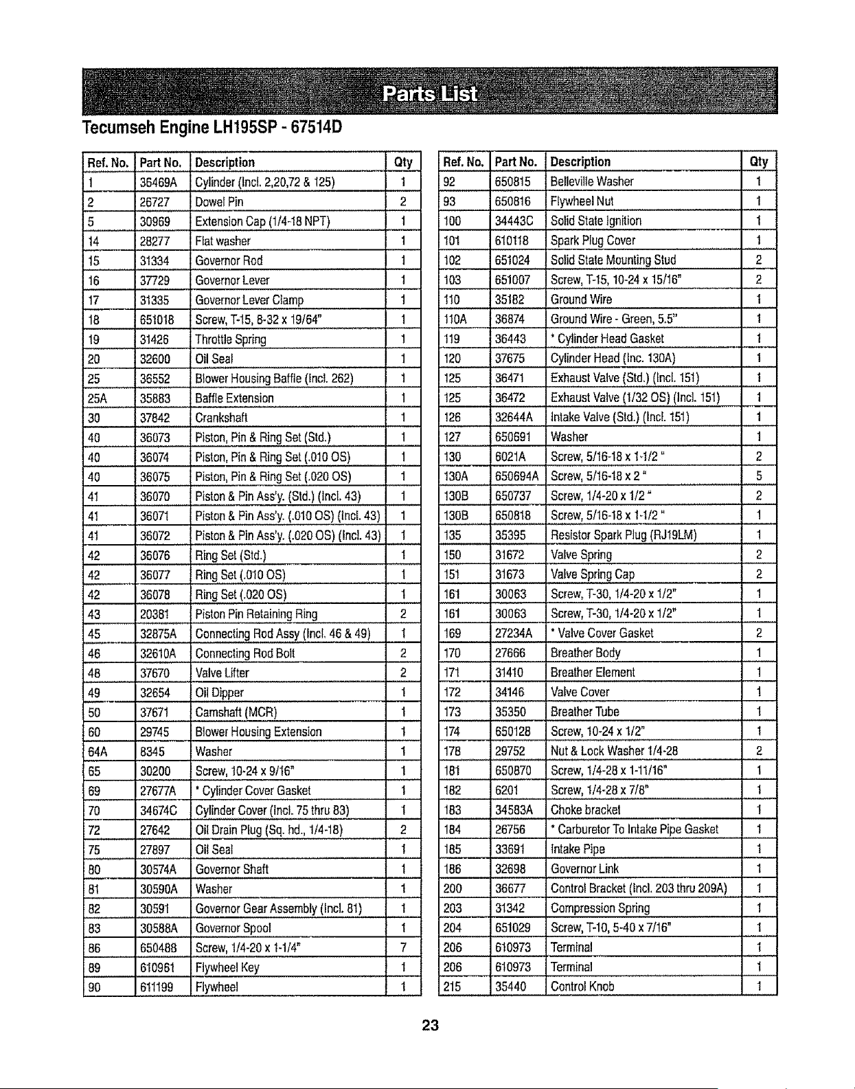
Tecumseh Engine LH195SP - 67514D
ReL No. Part No. Description _ _ Qty_-
1 36469A Cylinder(Incl.2,20,72& I25) 1
2 26727 DowelPin 2
5 30969 ExtensionCap(1/4-18NPT) _ 1
t4 28277 Flatwasher 1
15 31334 GovernorRod 1
16 37729 GovernorLever 1
17 31335 GovernorLeverClamp 1
18 651018 Screw,T-15,6-32x 19/64" 1
19 31426 ThrottleSpring 1
20 32600 OilSeal 1
25 36552 BlowerHousingBaffle0ncL262) 1
25A 35883 BaffleExtension 1
30 37842 Crankshaft 1
40 36073 Piston,Pin& RingSet(Std.) 1
40 36074 Piston,Pin& RingSet(.010OS) 1
40 36075 Piston,Pin& RingSet(.020OS) 1
41 36070 Piston& PinAss'y.(Std.)(Incl.43) 1
41 36071 Piston&PinAss'y.(.010OS)(lncL43) 1
41 36072 Piston&PinAss'y.(.020OS) (Incl.43) 1
42 36076 RingSet(Std.) t
42 36077 RinqSet(.010OS) l
42 36078 RingSet(.020OS) 1
43 20361 PistonPinRetainingRing 2.....
45 32875A ConnectingRodAssy(lncL46& 49) I
46 32610A ConnectingRodBott 2
48 37670 ValveLifter 2
49 32654 OilDipper I
50 37671 Camshaft(MCR) 1
60 29745 BlowerHousingExtension 1
64A 8345 Washer 1
65 30200 Screw,t0-24 x 9116" 1
Ref. No. Part No. Description Qty
92 650815 Belleville Washer 1
93 650816 FlywheelNut 1
!00 34443C SolidS!a!eIgnition 1
101 610118 SParkPlugCover ............ ?........
102 651024 SolidStateMountingStud 2
103 651007 Screw,"1"-t5,t0-24x 15/16" 2
110 35182 GroundWire 1
110A 36874 GroundWire- Green,&5" _ 1
119
120
125
125
126
127
130
130A
130B
130B
135
150
15t
161
16i
169
36443 : * CylinderHeadGasket . 1
37675 CylinderHead{fnc.130A) 1
36471 ExhaustValve(Std.)(Incl.151) _ 1
36472 ExhaustValve(1/32OS)(IncL151) 1
32644A intakeValve(Std.)(Incl.151) 1
650691 Washer 1
6021A Screw,5/16-18x 14/2 = 2
650694A Screw,5/16-18x 2° 5
650737 Screw,1/4-20x 1/2= 2
650818 Screw,5/16-18x 1-t/2" 1
35395 ResistorSparkPlug(RJ19LM) 1
31672 ValveSpring 2
31673 VaLveSpringCap 2
30063 Screw,T-30,t/4-20x 1/2" 1
30063 Screw,T-30,t/4-20x 1/2" 1
27234A * ValveCoverGasket 2
170
17l
172
173
174
178
181
27666 BreatherBody 1
31410 BreatherElement 1
134146 ValveCover 1
35350 BreatfierTube 1
, , ,,,, .....
650128 Screw,10-24x 1/2" 1
29752 Nut&LockWasher1/4-28 2
650870 screw,i/4-28 x 1-11/16. 1
69 27677A
70 34674C
72 27642
75 27897
80 30574A
81 30590A
82 30591
83 30588A
86
89
90
* CylinderCoverGasket 1
CylinderCover(Incl.75 thru83) 1
OilDrainPlug(Sq.hd., 1/4-18) 2
OilSeal I
GovernorShaft t
Washer 1
GovernorGearAssembly(Incl.81) 1
GovernorSpool I
182 6201
183 134583A
184 26756
185 33691
186 32698
200 36677
203 31342
204 651029
206 610973
650488 Screw,1/4-20x 1-1/4" 7
610961 FlywheelKey 1
611199 Flywheel 1
Screw,1/4-28x 7/8" 1
Chokebracket 1
CarburetorTo IntakePipeGasket 1
IntakePipe 1
GovernorLink 1
ControlBracket(Incl.203 thru209A) 1
CompressionSpring 1
Screw,T-10,5-40x 7/16" !
Terminal 1
Terminal I
ControlKnob I
206 610973
215 35440
23
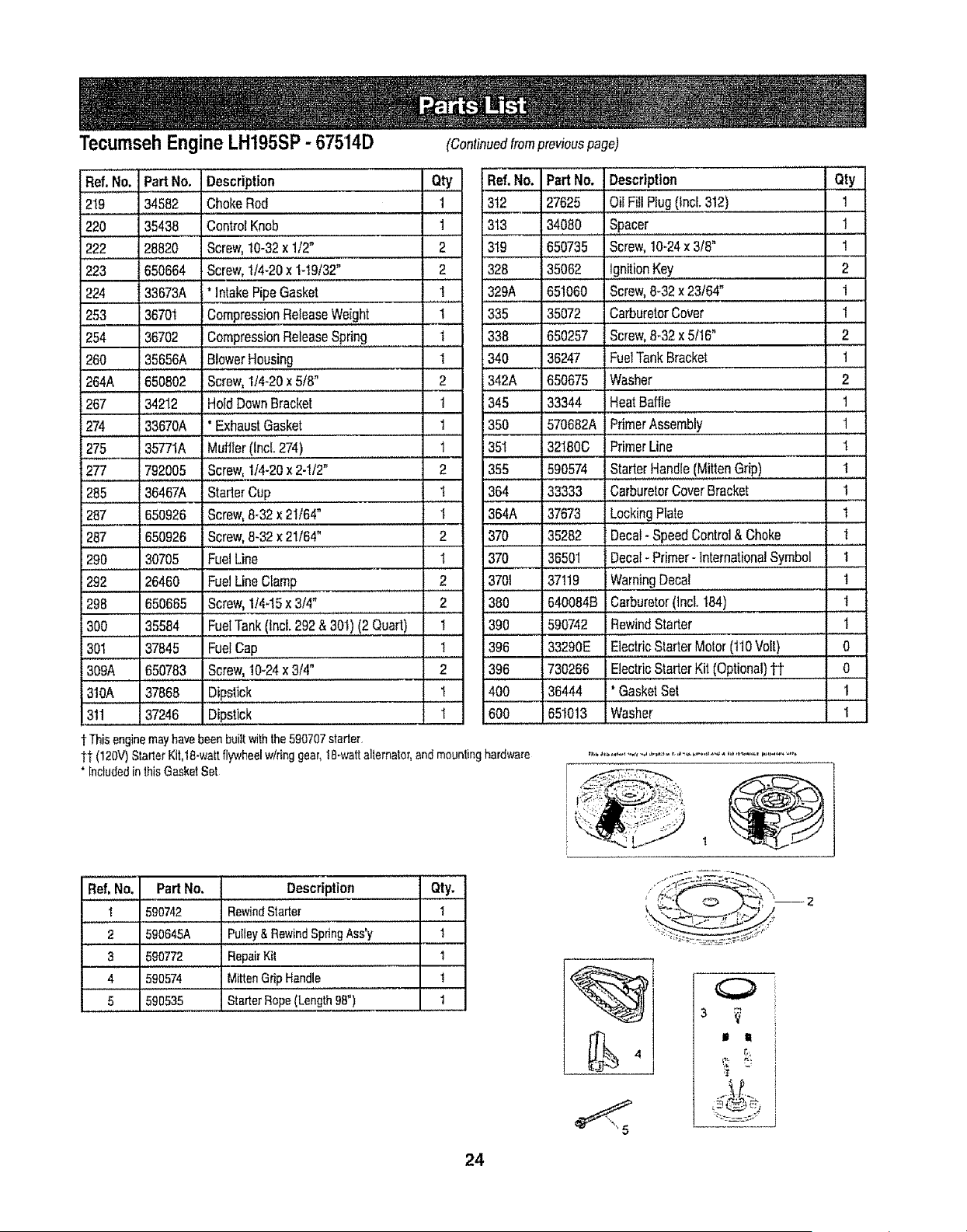
Tecumseh Engine LH195SP - 67514D (Continuedfrompreviouspage)
Ref.Noo =artNo, Description Qty Ref.No;
219 34582 ChokeRod 1 312 i
220 35438 ControlKnob 1 313
222 28820 Screw,10-32x 1/2" 2 319
223 650664 Screw,1/4-20x 1-19/32" 2 328
, ,, .... ,,,,,,,,
224 33673A * IntakePipeGasket 1 329A
253 36701 CompressionReleaseWeight 1 335
254 36702 CompressionReleaseSpring 1 ...3.38
260 35656A BlowerHousing 1 340
264A 65080.2.....'.Sc.[ew,...!.!4-20x 5/8" 2 342A
267 34212 HoldDownBracket 1 345
274 33670A ' ExhaustGasket 1 350
PartNo. Description : Qt._L
27625 OilFillPlug(tncL312) 1
34080 SPacer............ 1
650735 Screw,10-24x 318" 1
35062 !gnitionKey 2
651060 Screw,8-32x 23/64" 1
35072 CarburetorCover 1
650257 Screw,8-32x 5/16" 2
36247 :FuelTankBracket 1
650675 Washer 2
33344 HeatBaffle 1
570682A PrimerAssembly i
, ,, ,,,,,........
275 i35771A
277 792005
285 i36467A
287 650926
287 650926
290 30705
292 26460
298 650665
300 35584
301 37845
309A 650783
310A 37868
311 37246
Muffler(Incl.274) 1
Screw,114-20x 2-1/2" 2
StarterCup 1
Screw,8-32x 21/64" t
Screw,8-32x 21/64" 2
FuelLine t 370
FuelLineClamp 2 3701
Screw,1/445x 3/4". .................................2 380
FuelTank(Incl.292 & 301)(2 Quart) 1 390
Fuel.c.a.o......... 1 396
screw,10-24x 3/4"... 2 396
Dipstick 1 400
Dipstick I
351 32180C PrimerLine 1
355 590574 StarterHandle(MittenGrip) 1
364 33333 CarburetorCoverBracket 1
364A 37673 Locking Plate I
370 35282 Decal-SpeedControl& Choke 1
36501 Decal-Primer-InternationalSymbol 1
37119 IWarningDecal 1
640084B Carburetor(1nc!.:....!.84) 1
590742 RewindStarter t
33290E ElectricStarterMotor(110Vo!l) 0
730266 ElectricStarterKit(Optional)tt o
36444 * GasketSet I
600 651013 Washer 1
t This engine may have been built with the 590707 starter,
tt (120V) Starter Kit,18-watt flywheel w/ring gear, 18-watt alternator, and mounting hardware
"[ncluded in this GasketSet
.....Ref, No. Pad No.
1 590742
2 590645A
3 590772
4 590574
5 590535
....Description Qty.
Rewind Starter 1
Pulley & Rewind Spring Ass'y t
Repair Kit 1
Mitten Grip Handle !
Starter Rope (Length 98") 1
O
It l
24
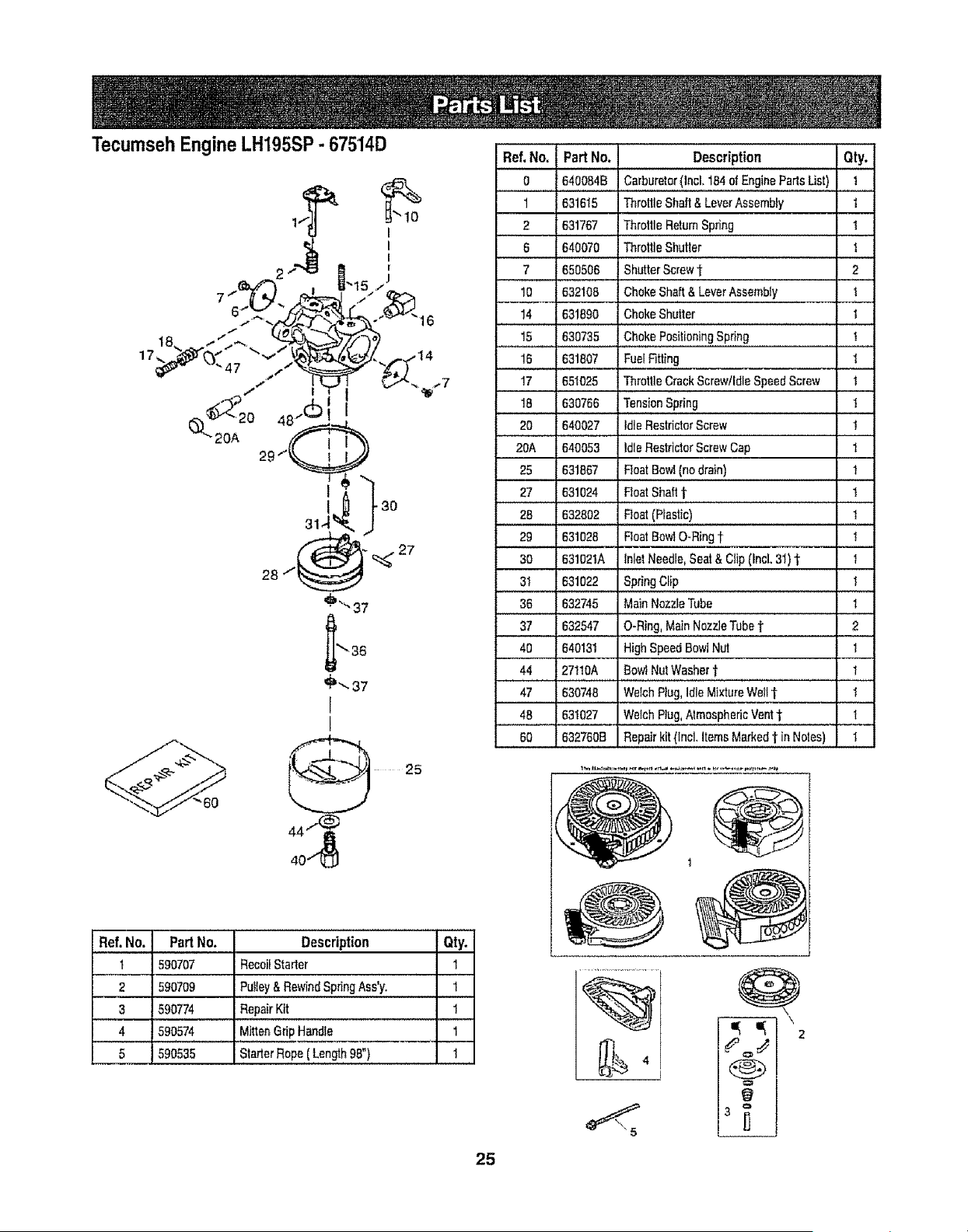
Tecumseh Engine LH195SP - 67514D
Ref, No. Part No, Description Qty.
0 640084B Carburetor(lncl, 164ofEnginePadsUst) 1
1 631615 ThrottleShaft& LeverAssembty 1
2 631767 ThrottleReturnSpring 1
6 640070 ThrottleShutler 1
650506. ShutterScrew_ . 2
10 632108 ChokeShaft&LeverAssembly t
14 _631890 . ChokeShutter . 1
15 _630735 ChokePositioningSpring 1
16 631807 FuelFitting 1
17 651025 ThrottleCrackScrew/IdleSpeeriScrew !
18 . 630766 TensionSpring 1
20 640027 IdleRestdetorScrew 1
20A 640053 IdleRestdetorScrewCap t
25 631867 RoarBowl(nodrain) 1
27 631024 FloatShaft1. 1
28 632802 Roat(Plastic) 1
29 631026 RoarBowlO-Ringt 1
30 631021A InletNeedle,Seat& Clip(incl,31)1 1
31 631022 Spi4ngClip 1
36 632745 MainNozzleTube 1
37 6325470.Ring,MainNozzleTubet 2
40 640131 HighSpeedBowlNut I
44 27110A BowlNutWasher"_ 1
47 630748 WelchPlug,Idle MixtureWetl1" 1
48 631027 WelchP3ug,AtmosphericVent1" .... t
60 6327608 Repairkit (lncL ItemsMarked1 in Notes) 1
Ref. No. Part No.
1 590707
2 590709
3 590774
4 590574
5 590535
Description Qty.
RecoilStealer 1
Pufley&RewindSpringAss'y. 1
RepairKit 1
MittenGripHandle 1
StarterRope( Length98") 1
25
%
\
,,
2
O
O

26
Manual del operador
L
®
Principio El_ctrico
MAQUINA QUITANIEVE DE 24", 4 CICLOS Y
NLimero de modelo 247.885550
PRECAUCION: antes de
utilizar este producto, lea
este manual y siga todas
las reglas de seguridad
y las instrucciones de
funcionamiento.
* SEGURIDAD
, MONTAJE
• OPERACION
• MANTENIMIENTO
• LISTADO DE PIEZAS
. ESPANOL
Sears, Roebuck and Co., Hoffman Estates, IL 60179, EE.UU.
Visite nuestro sitio web: www.sears.com/craftsman

DeclaraciEn de garantia ................................P&gina 28
Etiquetas de seguridad .................................P_gina 29
Reglas de operaciEn segura ................................P&ginas 30-31
Configuraci6n y ajuste ..................................................P_ginas 32-33
Conozca su m_quina quitanieve ................P&gina 34-35
Operaci6n ..........................................................PAgina 36-37
Mantenimiento y servicio ..................................PAgina 38-41
Almacenamiento fuera de ternporada y soluci6n de
problemas ..................................................................................PD.gina 42-43
Numero de servicio ............................................Cubierta posterior
Garantiade dosaEosparala m_quinaquitanieveCraftsman
Durante[losariesapartirdelafechadecompra,siemprequea estarn&quinaquitanievese le realiceel serviciode mantenimiento,lubricaci6n
y puestaapuntodeacuerdoalas instruccionesdelmanualdel propietario,Searsreparar_sincargocualquierdefectode materialeso manede
obra.Si esta m_quinaquitanieveCraftsmanseutitizaparaprop6sitoscomerciateso de alquiler,esta garantiase aplicas61odurante30diasa
parlirdelafechadecompra. Estagarantfanocubre:
• Elementosdesechablesquesedesgastanperelusenormal,incluyendoentreotros,zapatasantideslizantes,placade raspadoy bujfas.
• Reparaeionesnecesariasdebidoaabuseo negligeneiadeloperador,incluyendoaboltaduradelcigOeEaly fallaperno realizarmantenimiento
deiequipode acuerdoconlasinstruccionescontenidasenel manualdeTpropietario.
ELSERV1CIODEGARANTiAESTD,DISPONIBLEPARALOSUSUARIOSQUELLEVENLAMD,QUINAQUITANIEVECRAFTSMANAL
CENTRODEPARTESy REPARACIONSEARSM_,SCERCANODENTRODELOSESTADOSUNfDOS
Estagarantfaesv_lidalJnicamentemientrasetproductoseutilicedentrode los EstadosUnidos
PARAUBICARELCENTRODEPARTESY REPARACIONSEARSM,_SCERCANO0 PARAPROGRAMAREL SERV+CIOTI_CNICO,SIMPLE-
MENTECOMUNiQUESECONSEARSALTELEFONO1=800+4-MY-HOME@+.
Estagarantialeotorgaderechoslegalesespecficos;ustedtambi_npuedetenerotrosderechos,foscualesvarfandeunestadoa otto.
SEARS,ROEBUCKANDCOo,D/817WA_HOFFMANESTATES,IL 60179
Acuerdosde protecci6nsobre reparaciones
Feticitacionesperhaberrealizadounaadquisici6ninteligenteEl
productoCraftsman@quehaadquiridoest,,diseEadoy fabricadopara
brindartouchesariesde funcionamientoconfiable
Perocometodoslosproductosavecespuederequerirde repara-
clones Esen esemementocuandoet disponerdeun acuerdode
protecci6nparareparacioneslepuedeahorrardineroy preblemas
Acontinuaci6nse detallanlospuntosincluidosen el acuerdo:
, Servicioexpertoprestadopernuestros12000 especialistasen
reparacionesprofesionales
• Servicioitimitadosincargoparalaspiezasy la manedeobraen
todaslasreparacionescubiertas
• Reemplazodelproductosino esposiblereparare!productocubierto
• Descuentode10%delprecionormaldel servicioy de laspiezas
relacionadasconelmismoquenoest_ncubiertasperel acuerdo;
ademats,10%dedescuentodefprecionormalde taverificaci6nde
mantenimientopreventive
• Ayudar_pidapertet_fono- asistenciatelefEnicaa cargode un
t_cnicodeSearsparalosproductosquerequierenreparaci6na
demicilio,adem_sde unaprogramaci6nconvenienteparalarepara-
ciSnAdquieraahoraun aeuerd0de pretecciSnparareparacionesy
prot_jasedeproblemasy gastosinesperados
Unavezadquiridoelacuerdo,puedeprogramare! serviciocon
tan s61orealizarunallamadatelef6nicaPuedeItamarencualquier
mementodetdiaodela noche,o programarunservicioen linea
Searsdisponede m_,sde 12000 especialistasenreparaciones
profesionalesquetienenaccesoa m_sde 4,5millonesde piezas
y accesoriosde grancalidad.Esteesel ripede profesionalismoen
el quepuedeconfiarparaquele ayudea profongartavidaOtildet
produclorecientementeadquiridoen losariespervenir,iAdquierahey
su acuerdode protecciEnparareparaciones!
Seaplican determinadaslimitacionesy exclusiones.Paraobtener
preciose informaci6nadicionalIlameal 1-800-827-665&
Servicio de instalaci6n de Sears
Sideseasolicitarla instalaci6nprofesionaldeSearsde aparatos
dom_sticos,dispositivospareabrirportones,calentadoresdeaguay
otrosarticulosdom_sticosimportantes,enlosEstadosUnidesliame
a! 1-800-4-MY-HOME@
Combustible:
Bujfas:
Mote:
SAE 5W-30
Gasolina sin plomo
Champion@ RJ19LM
Tecumseh LH195SP
Nt]mero de modelo ...............................................................................
Numero de serie .................................................................................................
Fecha de compra .........................................................................................
Registre arriba el numero del modelo, el nt_mero
de serie y la fecha de compra
28
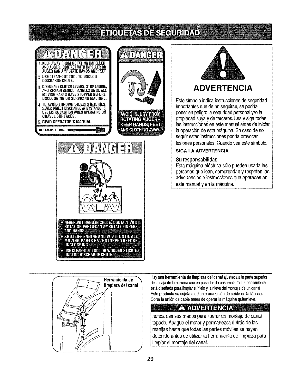
loKEEPAWAYFROMROTATINGIMPELLER
ANDAUGER,,CONTACTWiTHIMPELLEROR
AUGERCANAMPUTATEHANDSANDFEET,,
2_USECLEAN-OUTTOOLTOUNCLOG
DISCHARGECHUTE°
3. DISENGAGECLUTCHLEVERS,STOPENGINE,
ANDREMAINBEHINDHANDLESUNTILALL
MOVINGPARTSHAVE,STOPPEDBEFORE
UNCLOGGINGORSERVICINGMACHINE°
4.,TOAVOIDTHROWNOBJECTSINJURIES.
NEVERDIRECTDISCHARGEATBYSTANDERS,
USEEXTRACAUTIONWHENOPERATINGON
GRAVELSURFACES,,
5. READ OPERATOR'S MANUAL.
-.-.----.Ira
ADVERTENClA
Este simbolo indica instrucciones de segufidad
importantesque de no seguirse,se podrfa
poner en peligro la seguridad personal y/o la
propiedadsuya y de terceros Lea y sigatodas
las instrucciones en este manual antes de iniciar
la operaci6nde esta m_quina.En case de no
seguirestas instrucciones podria provocar
lesiones personales, Cuando yea este sfmbolo,.
SIGA LA ADVERTENClA,
Su responsabilidad
Estam_quinael_ctricas6topuedenusarfalas
personasque lean,comprendany respetenlas
advertenciase instruccionesque aparecenen
estemanualyen la m_.quina.
f
Herramienta de
_iezadelcanal
Hayunaherramientadelirnpiezadelcanalajustadaalapartesuperior
delacajadela barrenaconunpasadorde ensambladoLaherramienta
est,_diseSadaparalimpiarelhieloy la nievede1monlajedeun canal
Esteproductosesujetamedianteunauni6ndecableen la f_brica..
Cortefauni6ndecableantesde operarla rn_.quinaquitanieve.
nunca use sus manos para liberar un montaje de canal
tapado. Apague el motor y permanezca detr_s de las
manijas basra que todas las partes m6viles se hayan
detenido antes de utilizar la herramienta de limpieza para
limpiar el montaje del canal
29
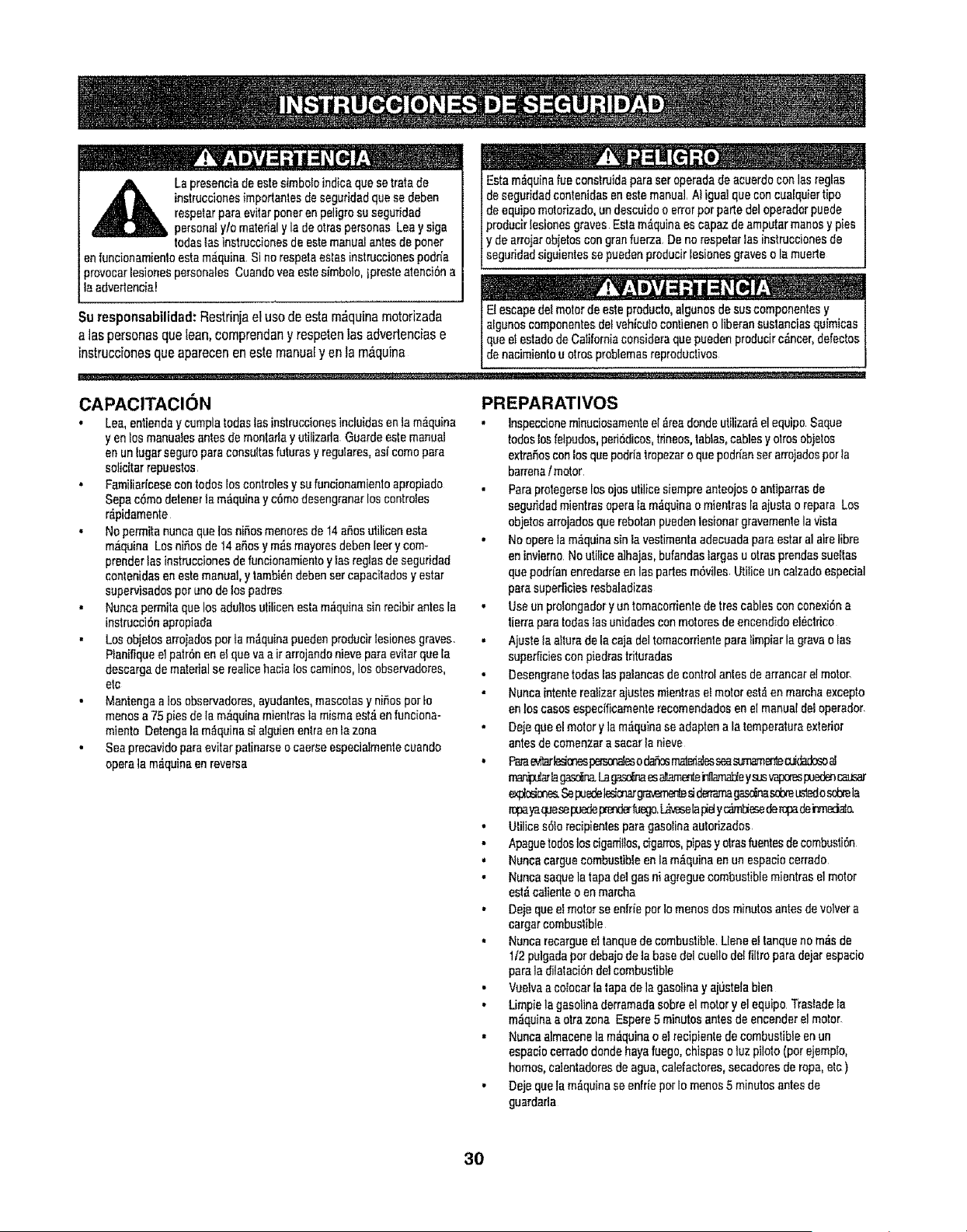
La presencia de este simbolo indica que setrata de
inslrucciones importanles de seguridad qua se deben
respetar para evitar poner en peligro su seguridad
personal yfo material y la de arras personas Lea y siga
redes las instrueciones de este manual antes de poner
en funcionamiento esta m_iquina Si no respeta astas instrucciones podr(a
provocar lesiones personales Cuando yea este simbolo, ipreste atenci6n a
la advedencia_
Suresponsabilidad:Restfinjaelusedeestam_quinamotorizada
ataspersonasquelean,comprendany respetenlasadvedenciase
instruccionesquaaparecenen estemanualy en la m,_quina
Esta m,iquina fue construida para ser operada de acuerdo con las reglas
de seguridad contenidas en este manual. At igua]que con cualquier ripe
de equipo motorizado, un descuido o error per parte del operador puede
producir lesiones graves Esta m_quina es capaz de amputar manes y pies
y de arrojar objetos con gran fuerza De no respetar ias instrucciones de
seguridad s gu antes se pueden product esionesgraves o la muerte
limmim .,.,, .,
El escape dei motor de este producto, algunos de sus componentes y
afgunos componentes del vehicula contieneno liberan sustancias quimicas
t qua el estado de California considera qua pueden producir c_,ncer,defectos
de nacimianIo u aires probtemas reproductivos
CAPACITACION
• Lea, entienda y cumplatodas las instrucciones incluidas en la m_,quina
yen fos manuates antes de monlarla y utilizada Guarde este manual
en un lugar seguro pare consultas futures y regulares, asi come para
solicitar repuestos.
. Familiar{case con redes Eoscontroles y su funcionamienlo apropiado
Sepa c6mo detaner la m_quina y c6mo desengranar los controles
r_pidamente
• No permita nunca qua los niffos menores de 14 aries utilicen eata
m_quina Los nifios de 14 aSos y m_s mayores deben leer y com-
prender las instrucciones de funcionamiento y las reglas de seguridad
contenidas en este manual, y tambi6n deban ser capacilados y ester
supervisados per uno de los padres
• Nunca permita que los aduitos ulilieen asia m_quina sin recibir antes la
instrucci6n apropiada
• Los objetos arrojados per ta m_quina pueden producir tesiones graves
Planifique el patr6n en el qua vaa ir arrojande nieve para eviler que la
descarga de matedal se realice haoia los caminos, los observadores,
etc
• Mantenga a los observadores, ayudantes, mascaras y nihos per to
menes a 75 pies de la m_quina mientras ta misma est_ en funciona-
miento Detenga la m_quina si alguien entra en la zona
• Sea precavido pare evitar patinarse o caerse especialmente cuando
opera la m_quina en reverse
PREPARATIVES
• Inspeccione minuciosamente el _ea donde utilizar_ el equipo Saque
redes los felpudos, pefi6dicos, tdneos,tabtas, cables y airesobjetos
extrafios con los que podda tropezar o qua podr(an ser arrojados perIa
barrena t motor
• Pare protegerse los ojos utilice siempre anteojos o antiparras de
seguridad mientras opera fa m_quina o mienlras Ia ajusta o repara Los
objetos arrojados que rebotan pueden iesionar gravemenle la vista
• No opera ta m_quina sin la vestimenta adecuada para ester al aire libra
en invierno No ulifice a]hajas, bufandas Iargas u arras prendas sueIlas
qua podr{an enredarse en las pades m6viles UtiIice un catzado especial
pare superficies resbaladizas
• Use un prolongador y un tomaconiente de Ires cables con conexiSna
Iierra para Iodas las unidades conmotores de encandido et6cttico
• Ajuste ta aitura de la caja del tomacorriente para timpiar la grave o las
superIieies con piedras trituradas
• Desengrane redes las paiancas de control antes de arrancare! motor
• Nunca intente realizerajustes mientras et motor esI_ en marcha excepto
en los cases espec(ficamente recomendados en el manual deI operador,
• Deje qua el motor y la m_qu;na se adapten ala temperatureextedor
antes de comenzar a sacar fa nieve
• Pare_n_s p_m od_m m_es _ mm_3mar__ _
mar_ularla_ La_ esattz,menle_ama_e ysusvapm_puc=_dencat_ar
expt_r_. Se puedel_mar g_ mdmama_ sdae _L_ osc6mla
ropeya_ese puedepr_bego, L,_ives_lapidyc_m_esede r_ dei"tneci_
• Ufilica s61o recipiantes para gasolina aulorizados
,, Apague redeslos ciganiifos, dgarros, pipes y olras fuentesde combusti6n
• Nunca cargue combustible en la m&quina an un espacio cerrado
• Nunca aaque la tapa del gas ni agregue combustible mientras el motor
esI_ caliente o en marcha
• Deje que ei motor se enfrie per lo menos dos minutes antes de velvet a
cargar combustible
', Nunca recargue el tanque de combustible. L[ene e! lanque no m_s de
1/2 pulgada per debajo de la base del cueIIo del filtro para dejar espacio
pare la dilataci6ndel combustible
• Vuelva a colocar [a tape de la gasoline y aj0stela bien
• Utopia la gasolina derramada sabre el motor y el equipo Traslade fa
m_quina a otra zone Espere 5 minutes antes de encender el motor_
• Nunca almacene fa m_quina o el recipienle de combustibfe en un
espacio cerrado donde haya fuego, chispas o tuz pilate (per ejempIo,
homes, calentadoresde agua, calefactores, secadores de rope, elc )
• Deje que la m_quina se enfr(e per Io menos 5 minutes antes de
guardada
3O
OPERACION
• No ponga las manes o los pies cerca de las piezas rotator_as,en la oaja
de la barrena t motor oen el montaje del canal de descarga El tentacle
con las piezas rotatodas puedeproducirla amputaci6n de manes y pies
• La palance de centre! de la bartena t motor es un dispositivo de segud-
dad, Nunca paso per alto su funcionamiento De hacerio la operaci6n de
la m_quina es desgosa y puede ocasionar lesiones,
• Las palancas de control deben funcienar bienen ambas direccionesy
regresar automaticamenteala posici6n de desengraneouandoselas
suelta
• Nuncaoperala m_quinasifalta un montaiedelcanal o si elmismoest_ dafado,
Mantengatodoslosdisp_vos de seguridaden sulugaryen fundonamiento,
• Nuoca encienda un motor en espacios cerrados oen una zone con poca
ventilaoiOn Elescape del motor centiene mon6xido de carbono, un gas
inodoro y telal
• No utilice la m_quina bajo {a intluencia del alcohol o las drogas
• El silenciador y el motor se calientan y pueden producir quemaduras No
los toque
o Sea sumamente precavidocuandooperelam_quinasobreuna
supe_ciecongravaoouandolacruceMant6ngasealertapotsise
presentanpeligrosocuHosotr6nsito
• Tonga ouidadocuando cambie de direcci6n o ouandoopere la m_quina
enpendienles
• Planifiqueelpatr6nan elque vaairarrojandonieveparaevitarque
[adescarga dematerial ee produzca hacia las ventanas, las parades,
los autom6viles, etc y eviler asl posibtes dados materiales o iesiones
producidas per los rebotes
, Nonce dirija la desoarga hacia los hides, los observadores y las
mascotas ni deje qua nadie se pare delante de la m_quina,
, No sobrecargue la capacidad de la m_quina tratando de sacar la nieve
muy r_tpidamente,
, Nunoa opera esla m6quina sin buena visibilidad o iluminaci6n Siempre
debe ester seguro de que eat&bien afirmado y sostenga bien las
manijas Camine, nunca corra
, Corte ]a corrienteala barrena/ motor cuando transpose la m6quina o
ouandola misma no est_ en use
• Nunca opera la m_quina aalta ve[ocidad de desplazamiento sobre
superficies resbatadizas, Mire hacia abajo y hacia atr_s y tonga cuidado
cuando vaya marcha atr_s,
• Si la m_,quinacomenzara a vibrarde manors anormat, detenga el motor,
desooneoteel cable de la bujia y p6ngafa de manors qua haga mass
centre el motor, Inspeccione ta m_quina mlnuciosamente pare vet si
esl,_dadada Repme todos los dados anles de encender y operar la
m_quina,
• Desengrane todaslas palancas de controly detenga el motor antes de
dejar la posici6n de operaei6n (detr_s de fas manijas),, Espere a qua la
barrens I motor se detenga per completeantes de destapar el montaje
del canal o realizerajustes e inspecciones
• Nunca ponga [asmanes en las aberluras de descarga o de recofecci6n,
Utiiice siempre la herramienta de limpieza que se adjunta pare destapar
fa abertura de descarga No destape el montaje del canal mientras el
motor est6 en funcionamiento Antes de destapario, apague el motor y
permanezca detr6s de las manijas hasta que redes las partes m6viles se
hayan detenido
• Use s6fo uniones y accesorios aprobados per el fabricante (per ejemplo,
poses pare las ruedas, cadenas para los neum#,ticos, cabinas, etc,)
• Si se presenlan situaoiones que no est_n previstas en este manual, sea
cuidadosoy use el sentido com0n Contacte con su centre de servicio
Sears pare obtener ayuda,
MANTENIMIENTO Y ALMACENAMIENTO
• Nunca manipule los disposilivos de seguridad de manera imprudente,r
Controle peri6dicamente que funcionen de forms adecuada Remitase a
las secciones de mantenimienlo y ajuste de este manual
• Antes de realizer ta limpieza, reparar o revisar la m_quina, desengrane
lodes las pataocas de controly detenga el motor Espere a que la bar-
rena I motor se detenga per complete Desconecte e! cable de la bujia
y p6ngalo de manera que hags mesa contra el motor pare evitar qua se
encienda de manera accidental
• Controle frecuentemente qua redes los pernos y tomillos esl6n bien
ajustados para comprobarque la m_quina se encuentra an condiciones
seguras de funcionamienlo Asimismo, realioe una inspecoi_n visual de
la m_iquinapare controlar si la misma eat& dafada
o No cambie la configuraci6n del regulader del motor ni acelere de-
masiado el mismo El regulador controla la velocidad m_xima segura de
operaoi6n del motor
• Lasplacesde raspadoylaszapa_s an_deslizantesquese usanconla m_quina
quitanievesedesgastany sedafan Paraprotegersu segundad,verifique
frecuentementeredeslos componentesy reempl_.celoss61ocm partesde los
fabricanlesde equiposoriginaJes(OEM) °Lautifizaci6nde l_ez&_quano curm
planconlas especilioacionesdeequiposoffginaJespodriatenorcome resullado
unren_miento incormclo,y adam,islaseguridadpodffaesiar comprom_4ida"
• Reviselos controles peri6dieamente pare verificarqua engranen y
desengranen adecuadamenle y ajustelos si es necesario Consulle la
secci6n de ajustes en este manual del operador pare obtener inslruc-
ciones
• Mantenga o reemplace tas etiqoetas de seguridad e instrucoienes seg0n
sea necesario,
• Respete las normas referentes ala disposici6n corrects y las reglamen-
taciones sobre gas, cembuslible, etc pare proteger el medic ambienle
• Antes de almaoenar la maquina enci6ndala unes minutes pare saear la
nieve qua hays quedado an ta misma y pare eviler asi que se congele la
barrena I motor.,
• Nunca almecene la m_quina o e! recipienle de combustible en un
espacio cerrado donde hays fuego, chispas o luz piloto come per
ejemplo, calenladores de ague, homes, secadores de rope, etc
• Consulle siempre el manual de funcionamiento pare conocer tas instruc-
ciones adecuadas pare e! almacenamiento fuera de temporada
No modifique el motor
Pare evitar lesiones graves o la muerte, no modilique el motor baio ninguna
circunstancia, Si cambia la configuraci6n del regulador el motor puede descon-
trolarse y operar a velocidades inseguras Nunoacambie [a configuraci6n do
f_brioa del regulador del motor
31
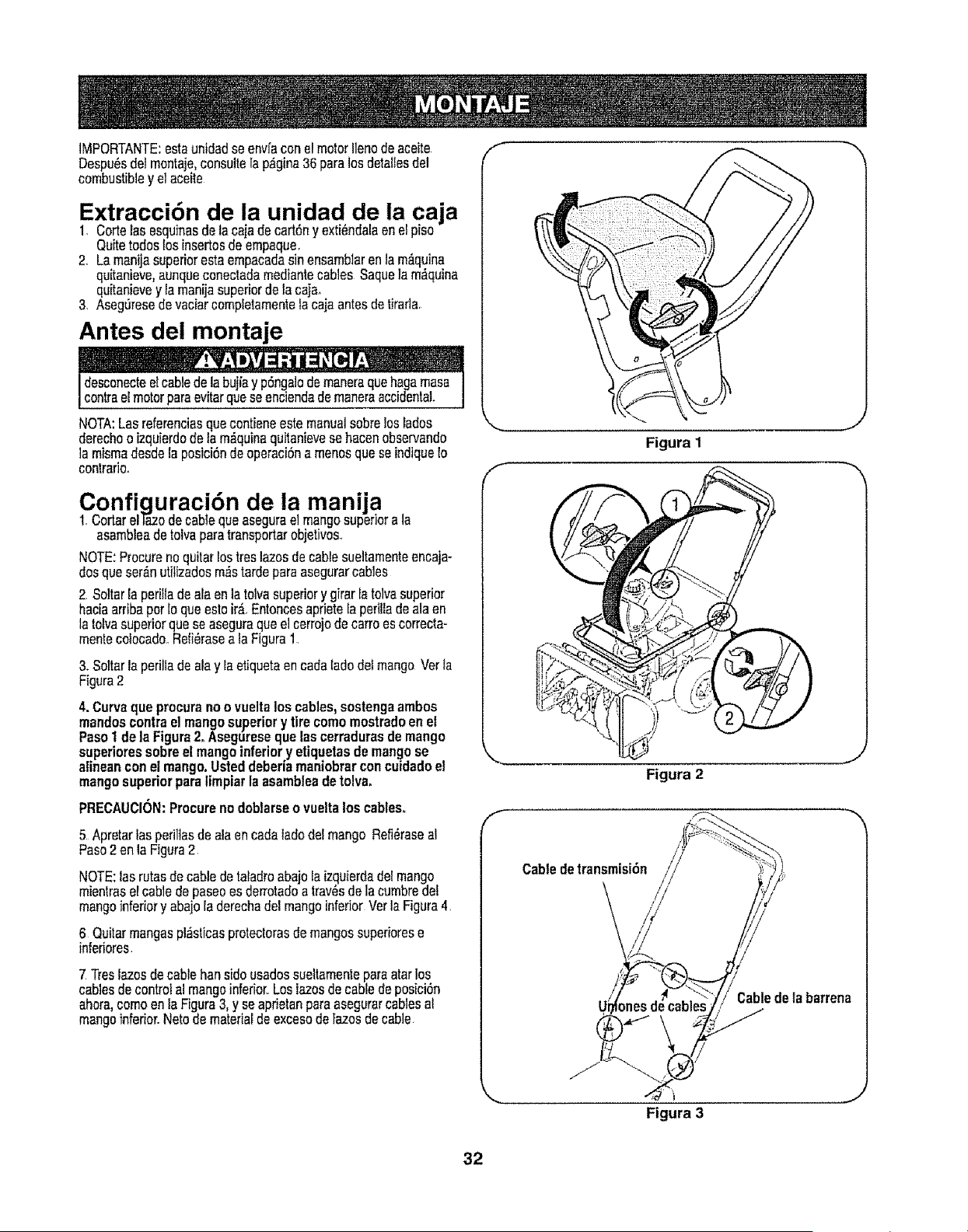
iMPORTANTE:estaonidadse envfaconelmotorIlenodeaceite
Despu_sdelmontaje,consultela p_gina36 paralos detallesdel
combustibley elaceite
Extraccibn de la unidad de la caja
1. Cortelas esquinasdetacajadecart6ny exti_ndalaene!piso
QuiteredesIosinsertosde empaque.
2. Lamanijasuperiorestaempacadasinensamblarenlam&quina
quitanieve,aunqueconectadamediantecables Saquelam_quina
quitanievey lamanijasuperiordelacajao
3. AsegOresede raciercompletamentetacaiaantesde tirarla.
Antes del montaje
desconecteelcabledelabujiayp6nga]odemaneraquehegamesa
centreelmotorpareevitarqueseenciendademaneraaccidental.
NOTA:Lasreferenciasquecontieneestemanualsobrelos lades
derechooizquierdodelam,_quinaquitanievese hacenobservando
]a mismadesdela posici6ndeoperaci6na menusqueseindique!o
contrario.
Conficjuraci6n de la manija
1. CortarelTazodecablequeasegurael mangosuperiorale
asambleadetetraparetransporterobjetivos..
NOTE:Procurenoquitarlostres lazesdecablesuettamenteenoaja-
dosqueser_nutitizadosm,_stardepareasegurarcables
2 Soltarla perilladeale en la toivasuperiory girarfetolvasuperior
haciaarribaperIo queestoir_.Entoncesapriete[aperittadealeen
la tofvasuperiorquese aseguraqueel cerrejode carroescorrecta-
mentecolocado..Refi_raseala Figure1.
3. Soltarla periltadealey IaetiquetaencadaladedelmangoVerIa
Figura2
4. Curvaqueprocuranoovueltalos cables,sostengaambos
mandoscentreel mangosuperiorytirecomemostradoen el
PasoI dela Figure2_Asegureseque lascerradurasdemango
superioressobreel mangoinferiory etiquetasde mangose
alineanconel mango.Usteddeberiamaniobrarconcuidadoel
mangosuperiorparalimpiarlaasambleadetolva.
PRECAUCION:Procurenodoblarseovueltaloscables°
5 Apratarlasperillasde aleen cadaladedefmango Refi_raseal
Paso2 en laFigura2
NOTE:las rutasdecabledetatadroabajoIaizquierdadelmango
mientraselcablede paseoesderrotadoa trav_sdelacumbrede_
mangoinferiory abajoladerechadelmangoinferiorVetla Figure4.
6 Quitarmangespl;_stfcasprotectorasde mangossuperiorese
inferiores.
7 Treslazesde cabtehen sideusadossueltamentepareatarlos
cablesdecontrolal mangoinferior.Loslazesdecabledeposici6n
ahora,comeen la Figure3, y seaprietanparaasegurarcablesal
mangoinferior.Nerode materialdeexcesodetazosde cable
f
f
Figura 2
Cabledetransmisi6n
//
;able de labarrena
t
Figura 3
32
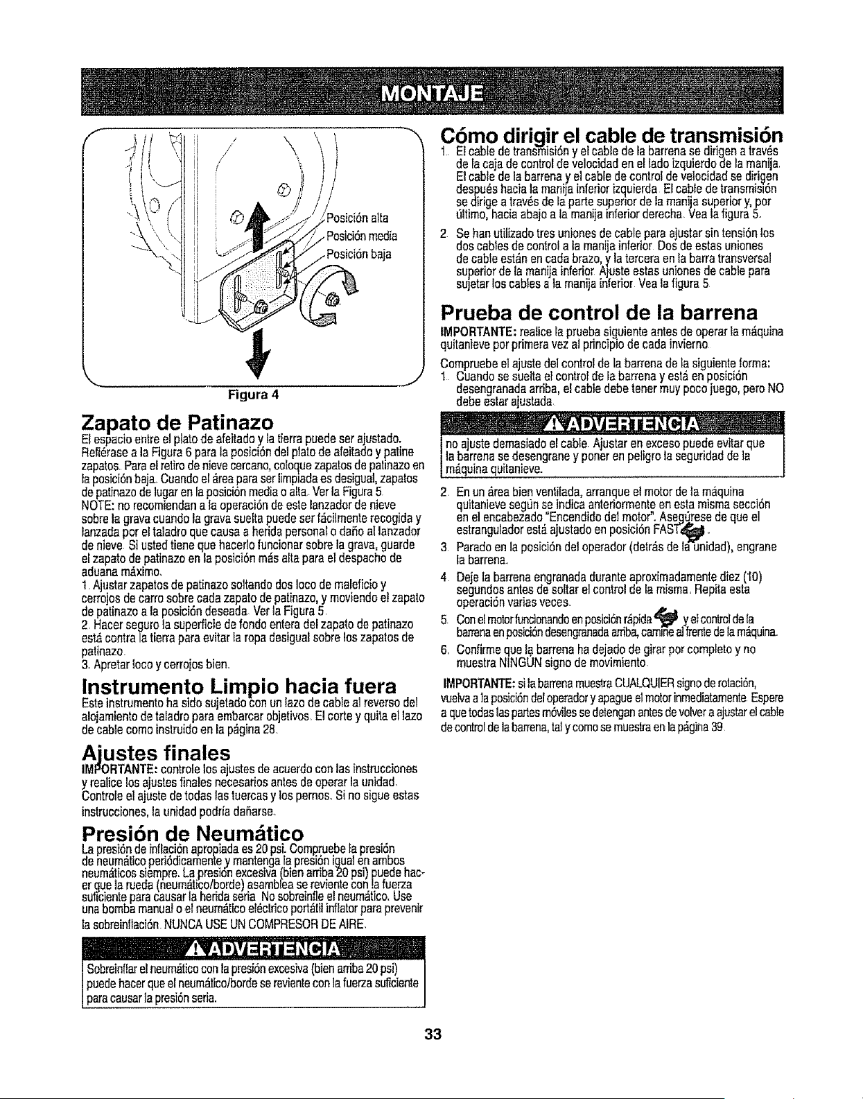
/ \
Figura 4
J
Zapato de Patinazo
Elespacioentree]platodeafeitadoy lafierrapuedeset ajustado.
Refi_rasea laFigura6 paralaposici6nde]platode afeitadoy patine
zapatos..Parael retiredenievecercano,coloquezapatosde patinazoen
laposici6nbaja.Cuandoel&reaparaserlimpiadaes desigua],zapatos
depatinazodelugarenlaposici6nmediaoalia.VerlaFigura5
NOTE:no recomiendana la operaci6nde estelanzadorde nieve
sobrela gravacuandola gravasueftapuedesetf_cilmenterecogiday
lanzadapereltaladroquecausaa heridapersonalo dafioa[lanzador
denieve Siustedtienequehaceflofuncionarsobrela grava,guarde
elzapatodepatinazoenlaposici6nrodsafiaparael despachode
aduanam#,ximo,
1 Ajustarzapatosde patinazosoitandodosIocode maleficioy
cerrojosdecarrosobrecadazapatodepatinazo,y moviendoetzapato
depatinazoa la posici6ndeseadaVer]aFigura5.
2. Hacerseguro]asuperficiederondoenteradelzapatodepatinazo
est_contralatierraparaevitarla ropadesigualsobreloszapatosde
patinazo.
3.Apretarlocoy cerrojosbien..
Instrumento Limpio hacia fuera
Esteinstrumentohasidesujetadoconunlazodecablealreversedel
a!ojamientode tatadroparaembarcarobjetivosEl cortey quitael ]azo
decablecomeinstruidoenla p_gina28.
Ajustes finales
IMPORTANTE:controlelosajustesde aeuerdoconlasinstrucciones
y realicelosajustesfinalesnecesariosantesdeoperarlaunidad
Controleetajustedetodaslas tuercasy losperno&Sinosigueestas
instrucciones,la unidadpodriadafiarse.
Presi6n de Neum.4tico
_apresi6ndeinflaci6napropiadaes20psi:Compruebefapresi6n
eneum_ticoperi6dicamen_e.ymantengarapresi6niqua_en amoos
neum,_ticossiempre.Lapresionexcesiva(bienarriba20psi)puedehac_
er.quelarueda(neum,_ticotboroelasambleaserevientecon!.afuerza
sullcienteparacausarla nerioaseria [,_oso_rein_leetneum,_tico,use
unabombamanua_o etneumdficoel6ctricoporl_titinflatorparaprevenir
lasobreinflaci6nNUNCAUSEUNCOMPRESORDEAIRE.
C6mo dirigir el cable de transmisibn
1..Elcabledetransmisi6ny elcabledelabarrenase dirigenatray,s
delacajadecontroldevelocidadenelladeizquierdodelamania
Elcabledelabarrenay elcablede controldevelocidadse dirigen
despu6shaciala manijainferiorizquierdaEfcabledetransmisl6n
se dirigea trav6sde Iapartesuperiorde Iamaniasuperiory, per
_ltimo,haca abajoa lamanijanferiorderechaVeafafigura5.
2 Se hanutilizadotres unienesdecableparaajustarsintensi6nlos
doscabtesde controla lamanijainferior Dosde estasuniones
decableest&nen cadabraze,y laterceraenlabarratransversal
superiordela manijainferiorANsteestasunionesde cablepara
sujetarloscablesa {amanijainferiorVeaiafigura5
Prueba de control de la barrena
tMPORTANTE:reaticela pruebasiguienteantesde operarlam_quina
quitanieveperprimeravezalprincipledecadainvierno
Compruebeelajustedeicontrolde la barrenade la siguienteforma:
1 Cuandose sueltael controlde la barrenay estaen posici6n
desengranadaarfiba,el cabledebetenormuypocojuego,poreNO
debeestarajustada
....... , m-v - ,
noajustedemasiadoel cable Ajustaren excesopuedeevitarque
]abarrenase desengraney poneren peligrola seguridadde]a
m_,quinaquitanieve.
2. Enun_reabienventiiada,arranqueelmotordeta m_quina
quitanievesegL]nseindicaanteriormenteenestamismasecci6n
enelencabezado"Encendidodelmotor".Aseg_resedequeel
estranguladorest_ajustadoenposici6nFAST_II ..
3 Paradeen la pesici6ndetoperador(detr_sde la'-unidad),engrane
tabarren&
4 Dejelabarrenaengranadaduranteaproximadamentediez(10)
segundosantesdesoltarelcontrolde la misma.Repitaesta
operaclonvanasvece&
5 Conelmotorfuncionandoenposici6nr_pida_ II ye_co_o]dela
barrenaenposici6ndesengranadaarriba,camlnea]#entedeiam_quJna.
6.. Confirmequela barrenaha dejadodegirarper completey no
muestraNINGUNsignode mevimiento.
IMPORTANTE:sitabarrenamues#aCUALQUIERsignoderolaci_n,
vuelvaalaposici6ndeloperadory apagueetmotorinmediatamenteEspere
a quetodaslaspatesm6vilessedetenganantesdevolveraajustarelcable
decontroldelabarrena,ta]y cornosemuestraenlap_gina39
Sobreinf_arelneum_ticoconlapresi6nexcesiva(bienarriba20 psi)
puedehacerqueelneum,_tico/bordeserevientecon]afuerzasuficiente
paracausarla presi6nseria.
33
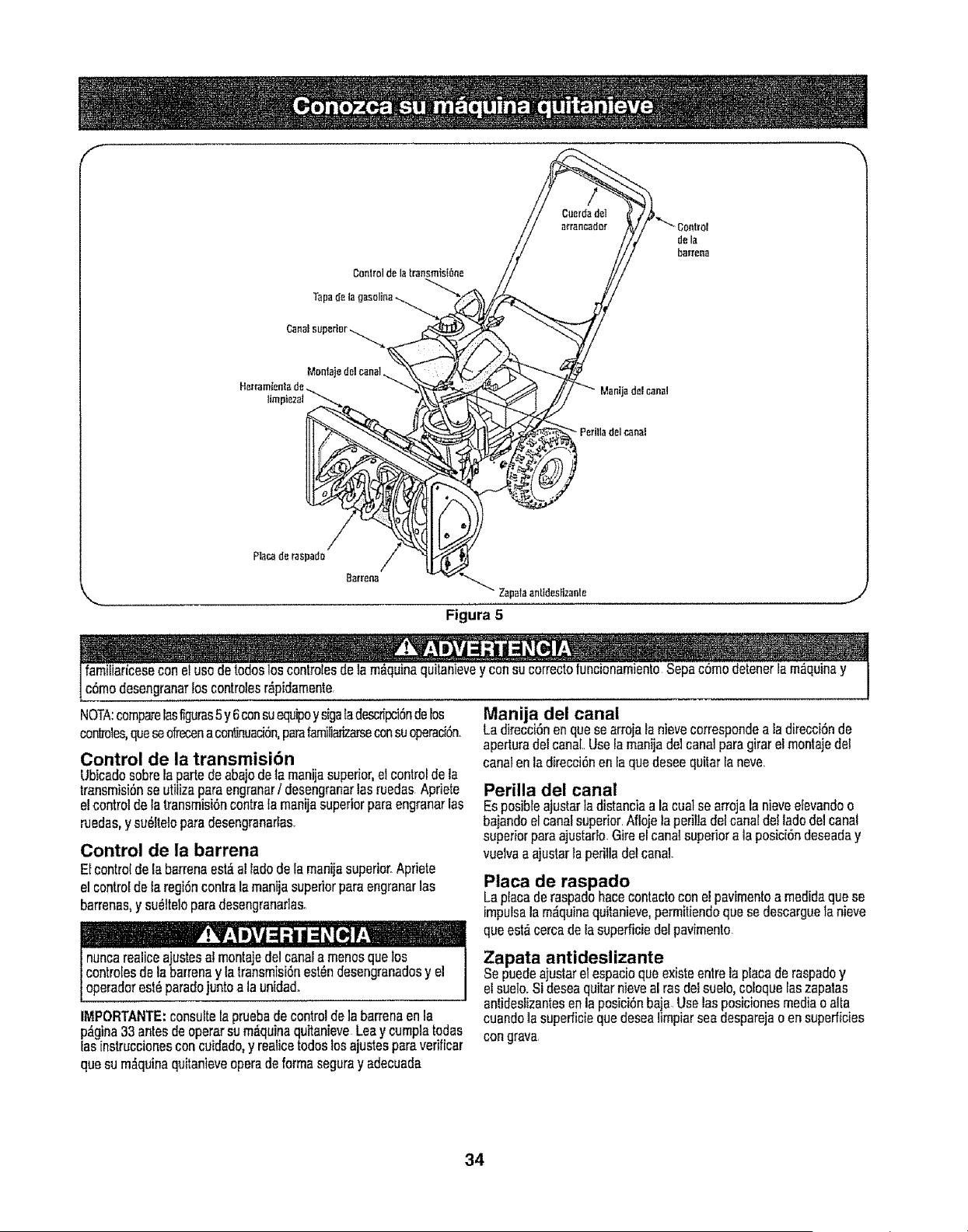
f
de la
t)ar:r_na
S_rrena
Zapataantldes[izante i,
Figura 5
c6modesengranarloscontrolesr_pidamente. I
NOTA:comparelasfiguras5 y6consuequipoysigaIadescripcidnderos
conlmies,queseofrecenacontinuaci6n,parafamiliarizarseconsuoperaci(_n.
Control de la transmisi6n
Ubicadosobrela partedeabajodeta manijasuperior,el controlde la
transmisi6nse utilizaparaengranarf desengranarlasruedas Apfiete
elcontroldelatransmisi6ncontrala manijasuperiorparaengranarias
ruedas,y su_ftetoparadesengranar_as.
Control de la barrena
Elcontroldefabarrenaest,.alIadede la manijasuperior°Apriete
el controldelaregidncontrala manijasuperiorparaengranarlas
barrenas,y su_tteloparadesengranaflaso
nuncarealiceajustesal montajedelcanala menosquelos
contro[esdela barrenay tatransmisi6nest_ndesengranadosy el
operadorest_paradejuntoala unida&
IMPORTANTE:consuffela pruebade controldelabarrenaenla
p_gina33antesdeoperarsum_quinaquitanieveLeay cumplatodas
las[nstruccionesconcukJado,y realicetodoslosajustesparaverificar
quesum,_quinaquitanieveoperadeformaseguray adecuada
Manija del canal
Ladirecci0nenquese arrojaIanievecorrespondea ladirecci6nde
aperturadelcanal..Uselamanijadelcanalparagirarel montajedel
canalenladirecoi6nenfa quedeseequitarlaneve
Perilla del canal
Esposibleajustarla distanciaa la cualse arrojala nieveefevandoo
bajandoel canalsuperior.Aflojela peril]adelcanaldelladedelcanal
superiorparaajustarlo.Gireelcanalsuperiora laposici6ndeseaday
vuelvaa ajustarla perilladelcanal.
Placa de raspado
Laplacaderaspadohacecontactoconelpavimentoa medidaquese
impulsalam_quinaquitanieve,permitiendoquesedescarguela nieve
queest,.cercadelasupefficiedelpavimente.
Zapata antideslizante
Sepuedeajustarelespacioqueexisteentrelaplacade raspadoy
elsuelo.Sideseaquitarnieveal rasdelsuelo,coloqueIaszapatas
antidestizantesenlapesici6nbaja.Uselasposicionesmediao alta
cuandola superficiequedeseafimpiarseadesparejaoen superficies
congrava
34
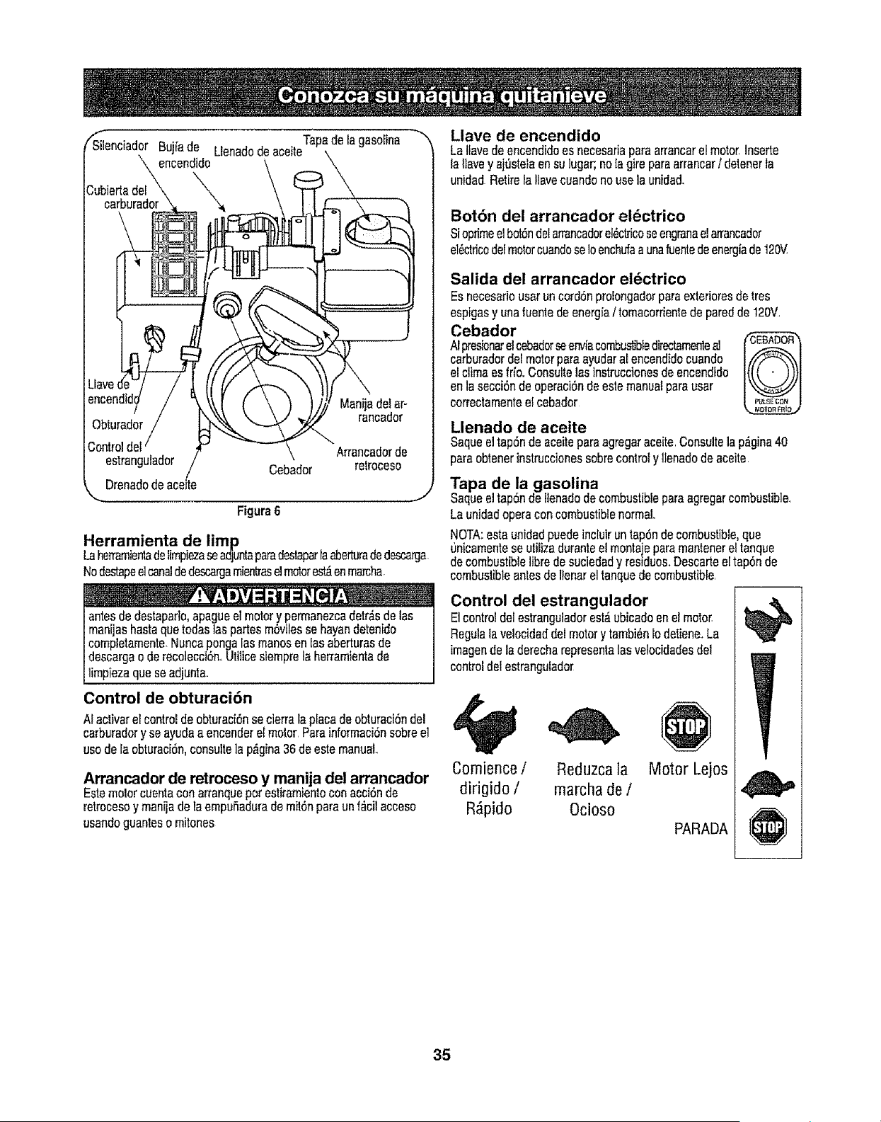
Bujia de . . , Tape de la gasoEina
Llenaoooe aceite
encendido
Drenadode aceite
Figure6
Herramienta de limp
LaherramientadefimpiezaseadjuntaparedestaparIaaberturadedescarga,
Nodestapeelcanaldedescargarnient]raselmotorest_enmarcha.
antesde destaparlo,apagueel motory permanezcadetr_sdelas
manijashastequetodastaspartesm6vilesse hayandetenido
completarnente-Nuncapongalasmanosen [asaberturasde
descargaoderecolecci6n..Utiiicesiemprela berrarnientade
limpiezaqueseadjunta.
Control de obturaci6n
AIactivarel controlde obturaci6nse derra la placedeobturaei6nde!
carburadory seayudaaencenderelmotorParainforrnaci6nsobreel
usode la obturaci6n,consultela p_gina36de estemanual
Arrancador de retroceso y manija del arrancador
Estemotorcuentaconarranquepot estiramientoconacci6nde
retrocesoy manijadetaempuBadurade mit6nparaun f_ciiacceso
usandoguantesomitones
Llave de encendido
Lallavedeencendidoes necesariaparearrancarelmotor.Inserte
latlavey aj_steiaensu lugar;nola gireparaarrancar/ deienerla
unidadRetiretaIlavecuandonousela unidad
Botbn dei arrancador el_ctrico
Sioprimeelbot6ndotarrancadorel_tficoseengranaelarrancador
eldctricodelmotorcuandoseIoenchufaa unafuentedeenergiade120V
Salida del arrancador el_ctrico
Esnecesariousarun cord6nprolongadorparaexterioresde tres
espigasy unafuentedeenergfa/ tornacorrientede paredde 120V
Cebador
AIpresJonarelcebadorseenviacombu_bledirectamenleal
carburadordel motorpareayudaral encendidocuando
elclimeesfrio.Consuilelasinstruccionesde encendido
enla secci6nde operaci6nde estemanualparausar
correctamenteel cebador
Llenado de aceite
Saqueeltap6ndeaceitepareagregaraceiteConsultelap_gina40
pareobtenerinstruccionessobrecontroly llenadodeaceite
Tapa de la gasolina
Saqueeltap6ndeiienadodecombustibleparaagregarcombustible.
Launidadoperaconcombustiblenormal.
NOTA:estaunidadpuedeincluiruntap6nde combustible,que
unicarnentese utilizedurantee! montajeparamantenerettanque
decombustiblelibredesuciedady residuos..Descarteeltap6nde
combustibleantesdeIlenarel tanquedecombustible.
Control del estrangulador
Elcontroldelestranguladorest_ubicadoen el motor.
Regulalavelocidaddelmotory tambi_nIodetiene..La
imagende la derecharepresentalas velocidadesdel
controldelestrangulador
Reduzca la
marcha de /
Ocioso
Motor Lejos
PARADA
Cornience /
dirigido /
R_pido
35
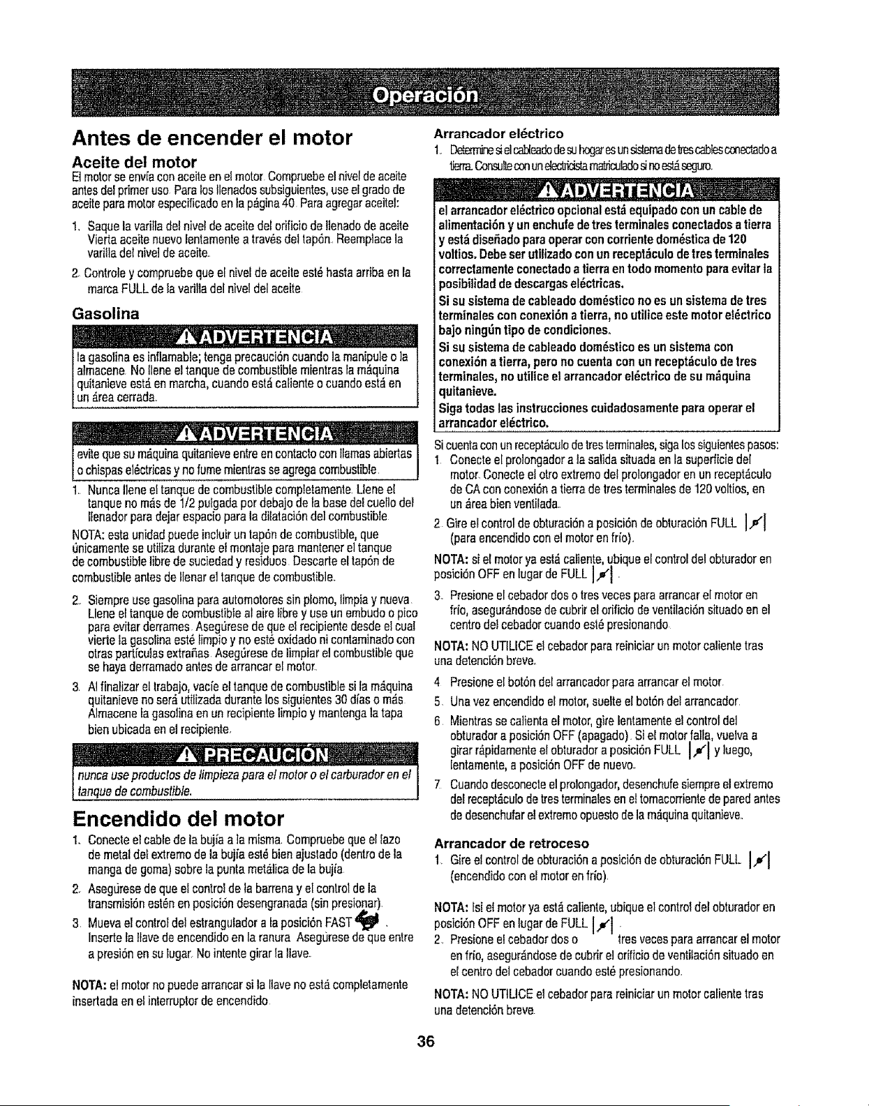
Antes de encender el motor
Aceite del motor
E1motorseenvfaconaceiteen etmotorCompruebeel nivelde aceite
antesdelprimeruse Parelostlenadossubsiguientes,useetgradede
aceiteparemotorespecificadoentap_gina40 Pareagregaraceitel:
1. Saquelavadttadefniveldeaceitedelorificiode Ilenadode aceite
Viertaaceitenuevolentamentea tray,s deItap6n.Reemplacela
variUadefnivelde aceite.
2. Controtey compruebequeel nivefde aceiteest_hastaarribaen la
marcaFULLdelavariliadel niveldelaceite
Gasolina
lagasolinaesinflamable;tengaprecauci6ncuandola manipuleo la
almacenaNoIleneel tanquedecombustiblemientrasfam_quina
quitanieveest,.enmarcha,cuandoest_calienteo cuandoest_en
un€=reacerrada.
evitequeSum_.quinaquitanieveentreenc0ntaCtoconllamasabiertas
ochspase_ctrcasy nofumementrasseagregacombustbe
1..NuncalieneeltanquedecombustiblecompfetamenteLleneel
tanquenom_isde1/2pulgadaperdebajodeta basedelcueltodel
llenadorparsdejarespaciopareIsdilataci6ndelcombustible
NOTA:estaunidadpuedeinciuirun tap6ndecombustible,que
0nicamentese utifizaduranteetmontsjepare mantenerel tanque
decombustiblelibredesuciedady residuesDescarteeltap6nde
combustibleantesdellenareltanquede combustible..
2.. Siempreusegasolinapareautomotoressinpiomo,limpiay nueva
Ueneel tanquedecombustibleaI airelibrey useun embudoo pico
pareevitarderramesAseg_resedequee!recipientedesdeelcue!
viertela gasolinaest6Iimpioy noest_oxidadoni contaminadocon
otrasparticulasextraSasAsegSresede limpiarel combustibleque
sehayaderramadoantesde arrancarel motor..
3 AIfinalizarel trabajo,vacieel tanquede combustiblesi la m_,quina
quitanievenoser_utilizadadursnteIossiguientes30 diesom_s
Almacenelagasolineenunrecipientelimpioy mantengaIs tapa
bienubicadaenelrecipiente..
• ! "" ,. O_,
n
nonceuseproductosde timpiezapareelmotoroelearburadoren el
lanquedecombustible.
Encendido del motor
1, Conecteelcablede la bujisaia misma Compruebequeel fazo
demetaldelextremede la bujiaest_bienajustsdo(dentrodela
mangadegoma)sobrelapuntamete.licede la bujia
2 Aseguresede queel controldeta barrenay elcontroldela
transmisi6nest_nenposici6ndesengranada(sinpresionar)
3 Muevael controldeIestrangutadora faposici6nFAST_ .
Insertela ltavede encendidoen IaranuraAsegtiresedequeentre
apresi6nensu lugarNointentegirarla llave..
NOTA:elmotornopuedearrancarsi laItavenoest,.completamente
insertadaenel interrupterdeencendido
Arrancador el_ctrico
1. Lg,_ sielcableadode_ begatesunsis_rnadeIrescab_ cmec'_doa
tierre,.Consulteconunel_ m_culado_noes_seguro
elarrancadorel_ctricoopcionalest_ equipadoconuncablede
alimentaci6ny unenchufedetresterminalesconectadosatierra
y est_dise5adoparaoperarconcorrientedom_sticade120
voltios.Debeserutilizadoconunrecept_culodetresterminales
correctamenteconectadoatierraentodomomentoparaevitarla
posibilidaddedescargasel_ctricas.
Si suststemade cableadodom_sticono es un sistemadetres
terminalesconconexi6na tierra,no utUiceestemotorel_ctrico
bajoning_3ntipode condiciones.
Si susistemade cableadodom_,sticoes un sistemacon
conexi6na tierra,perono cuentacon unrecept_culode Ires
terminsles,noutiliceelarrancadoreldctricodesu m_quina
quitanieve.
Sigatodaslas instruccionescuidadosamenteparaoperarel
arrancadorel_ctrico.
Sicuentaconun recept_culode IresIerminales,sigalossiguientespasos:
I Conecteel prolongadora Is salidasituadsenla superficiedel
motor.Conecteel ottoextremedotprolongadoren un recept_culo
deCAconconexi6na tierradeIres terminalesde 120voltios,en
un_reabienventilada.
2 Gireelcontroldeobturaci6na posici6nde obturaci6nFULL I,v'j
(pareencendidoconel motoren frio).
NOTA:si el motoryaest,_caiienteubiqueel controldelobtursdoren
posici6nOFFenlugardeFULL Jl '
3- Presioneel cebadordosotresvecesparearrancarelmotoren
frio,asegur_ndosedecubdrel orificiodeventilaci6nsituadoen el
centredeicebadorcuandoest_presionando
NOTA:NOUTILICEelcebadorparereinieiarunmotorcalientetras
unadetenci6nbreve.
4 Presioneel bot6ndelarrancadorparearrancarelmotor.
5 Unavezencendidoel motor,suelteel bot6ndel arrancador
6 Mientrassecalientael motor,gire lentamenteelcontroldeI
obturadora posici6nOFF(apagado)Siel motorfalla,vuelvaa
girarr_pdamentee obturadora posic6n FULL _ y uego,
Ientsmente,eposici6nOFFdenuevo.
7 Cusndodesconecteelprolongador,desenchufesiempreelextreme
delrecept_culode Iresterminslesen eltomacon'ienledeparedantes
dedesenchufarel extremeopuestode la m;_quinaquitanieve.
Arrancador de retroceso
1. Gireel controlde obturaci6na posici6nde obturaci6nFULL Ill
(encendidocon el motorenfrio)
NOTA:fsiel motoryaest_caliente,ubiqueel controldel obturadoren
posJci6nOFFenlugerde FULLIll
2. Presioneelcebadordoso iresvecesparearrsncarel motor
enfrio,asegur_ndosedecubrirel ofificiodeventifaci6nsitusdoen
elcentredelcebadorcuandoest_presionando.
NOTA:NOUTtLICEel cebadorpsrareiniciarun motorcafienteIres
unadetenci6nbreve
36
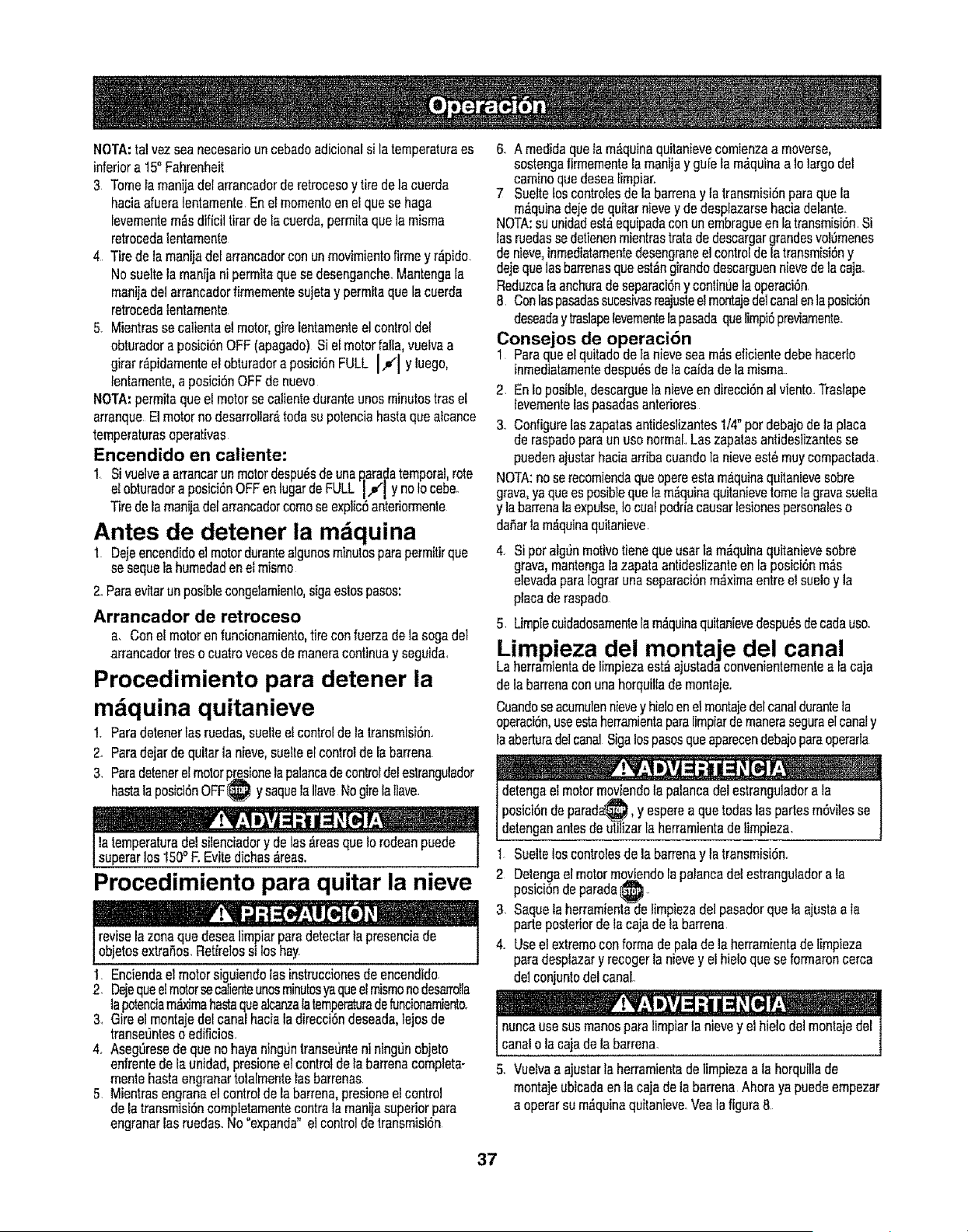
NOTA:tel vezseanecesadouncebadoadicionalsi latemperaturaes
inferiora 15_Fahrenheit
3 Tomela manijadelarrancadorderetrocesoy tire delacuerda
haciaafueralentamenteEn el mementoenelquase haga
fevementem_.sdificiltirardela caerda,permitaquela misma
retrocedetentamente
4 Tirede la rnanijadel arrancadorcon unmovimientofirmey r_pido
Nosueltelamanijani permitaquese desenganche.Mantengala
manijadelarrancadorfirrnementesujetay permitaquela cuerda
retrocedalentamente
5. Mientrasse calientael motor,girelentamenteelcontroldel
obturadora posiciSnOFF(apagado)Si elmotorfal[a,vuelvaa
girarr_pidamenteel obturadora posiciSnFULL I,.,(I y luego,
lentamente,a posiciSnOFFde nuevo
NOTA:permitaqueelmotorsecalienteduranteunosminutestres el
arranqueElmotornodesarrollar_todasu potenciahastaquaalcance
temperaturesoperativas
Encendido en caliente:
1 Si vuelvea arrancarunmotordespu_sdeunaQaradatemporal,rote
elobturadora posici6nOFFen tugarde FULL I,_1 y no tocebe.
Tiredelamanijadelarrancadorcomeseexplic5anteriorrnenle
Antes de detener la m quina
l Dejeencendidoel motordurantealgunosminutesparepermitirque
sesequelahumedadenel mismo
2..Pareevitarunposiblecongelamianto,sigaestospesos:
Arrancador de retroceso
a. Conelmotorenfuncionamiento,tireconfuerzade la sogadel
arrancadortresocuatroracesdemaneracontinuay seguida.
Procedimiento para detener la
m iquina quitanieve
1_Paredetenerlas ruedas,suelteelcontrolde la lransmisidn..
2..Paredejardequitarla nieve,suelleel controlde labarrena
3. Paredetenerelmotorp_sionelapalancadecontroldeleslranguladcr
hastelapos_ciSnOFF_ y saquelaIlaveNogirelatiara.
! '._ _ k .'-
I latemperaturedel silenciadory de las_reasque1orodeanpuede f
I superarlos 150"F.Evitedichas_reas. 1
Procedimiento para quitar la nieve
reviselazonequadesealimpiarparedetectarla presenciade
objetosextraSos.Retireos s oshay.
I Enciendael motorsiguiendolasinstruccionesdeencendido.
2 Dejequae!motorsecalienteunasminutesyaqueel mismonodesarrolla
tapetenciam_ma hastequealcanzalatemperaturedefuncionamiento.
3. Gireel montajede!canalhaciala direcci6ndeseada,lejosde
transe_Jnteso edificios.
4. Asegl)resedequanohayaning'Jnlranseuntenining0nebjeto
enfrentedelaunidad,presioneelcontrotdela barrenacomplete-
montehastaengranartotalmentelasbarrenas
5 Mientrasengranael controlde la barrena,presioneel control
delatransmisiSncompletamentecontrala manijasuperiorpara
engranarlasruedas_No"expanda"elconlrolde transmisiSn
6. A medidaqualam_quinaquitanievecomienzaa moverse,
sostengafirmementelamanijay guietam&quinaalo largodel
caminoquedesealimpiar.
7 Suelteloscontrolesdelabarrenay latransmisiSnparaquela
m_4quinadejede quitarnievey de desplazarsehaciadelante.
NOTA:suunidadest_equipadaconunembragueen la transmisiSn.Si
lasruedassedetienenmientrastratade descargargrandesvol0menes
denieve,inmediatamentedesangraneel controlde la transmisiSny
dejequelasbarrenasquaest_ngirandodescarguennievede la caja.
Reduzcala anchuradeseparaciSny conlinL_elaoperaciSn
8 Conlaspasadassucealvasreajusteelmentajedelcanalanlaposici6n
deseaday lraslapelevementelapasadaqualimpi5previarnente
Consejos de operaci6n
I Parequeel quitadode tanieveseam_seficientedebehaceflo
inmediatamentedespu_sdetacaidadelamisma.
2 En lo posible,descarguela nieveen direcciSnal viento.Traslape
fevementelaspasadasanteriores
3..ConfigureIaszapatasantideslizantesI/4" perdebajodelaplace
deraspadepareunusenormal..Laszapalasantideslizantesse
puedenajustarhaciaarribacuandolanieveest_muycompactada
NOTA:noserecomiendaquaoperaestamaquinaquitanievesobre
grave,ya quaespasiblequetam,_quinaquitanievetomelagravesuella
y labarrenalaexpulse,Iocualpodriacausarlesionespersonaleso
daBarlam_,quinaquitanieve
4. SiperalgSnmotivetienequeuserla m_quinaquitanievesobre
grava,mantengalazapataanlideslizanteen la posici6nm_s
elevadapareIograrunaseparaciSnm_ximaentreel sueloy la
placade raspado
5 Limpiecuidadosamentela m_quinaquitanievedespu#sde cadause.
Limpieza del montaje del canal
Laherramientade limpiezaest_ajustadaconveniantementea Iacaja
delabarrenaconunahorquiltademontaje.
Cuandosaacumulennievey hieloenel montajedelcanaldurantela
operaci6n,useasiaherramientapareIimpiardemanerasegurael canaly
laaberturadelcanalSigalospasosqueaparecendebajoparaoperaria
detengael motormoviendola palancadelestranguladorala
posiei6ndeparada___,y esperea queredeslas partesm6vilesse
datenganantesdeutitizarla herramientadelimpieza.
I Suelteloscontrolesde labarrenay latransmisiSn..
2 Detengael motormoviendolapatancadelestranguladorala
posiciOndeparadei_ ..
3. Saquetaherramientade limpiezadel pasadorquela ajustaala
parteposteriordela cajadela barrena
4. Useelextremeconformadepaledelaherramientadelimpieza
paradesplazary recogerlanievey el hieloque seformaroncerca
delconjunlodelcanal..
- ; ....
nuncausesusmanespara limpiarla nievey el hielodelmontajedel
1cane o a cajade a barrena, j
5.. Vuelvaa ajustarfaherramientade limpiezaala horquillade
montajeubicadaenla cajadela barrenaAhoraya puedeempezar
aoperarsu m_quinaquitanieve.Veala figura8.
37
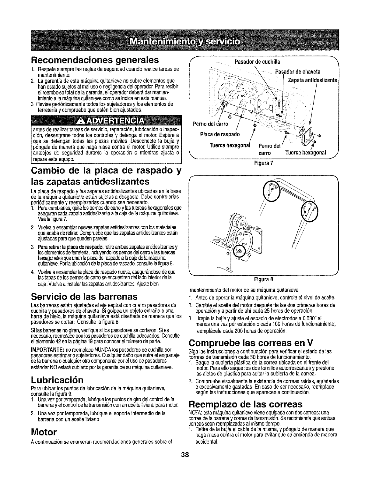
Recomendaciones generales
1+ Respetesiemprelasreglasde seguridadcuandoreaiicetareasde
mantenfmiento.
2.. La garantiade estam_quinaquitanievenocubreelementosqua
henestadosujetosalmatuseo negligenc+adetoperadorParerecibir
elreembolsototaldeIagarant{a,el operadordeber_darmanten-
imientoala m_quinaquitanievecomeseindicaenestemanual
3 Reviseperi6dicamentetodoslossujetadoresy loselementosde
ferretedaycompruebequaest_nbienajustados
antesderealizertareasdeservicio,reparac+Sn,lubricaci6no inspec-
ci6n,desengraneredeslos controlesy detengael motor.Esperea
que se detengantodaslas piezas m6viies Desconecteta bujiay
p6ngalademaneraquahagsmasscontraelmotor_Utilicesiempre
anteojosde seguridaddurantela operaci6no mientrasajusta o
reparaesteequipo.
Cambio de la placa de raspado y
las zapatas antideslizantes
Laplacederaspadoy [aszapatasantidestizantesubicadasen{abase
dela m_quinaquitan+eveest_nsuetasa desgaste.DebecontroIades
peri6dicamentey reemplazarlescoandoseanecesario.
1_ Parecambiartas,quiteIospemosdecan'oy{astuercashexagonalesque
asegurancadszapataantideslizantea Iacajadela m_quinaquitanieve
Veatafigure7.
2+ Vuelvaaensamblarnusvaszapatasantideslizantesconlosmateriates
quaacabaderetirar.Comprusbequataszapatasantidestlzantesest_,n
ajustadasparaquaquedenparejss
3. Pareretirarlap{acederaspado:retireambaszapatasantidestizantesy
loselementosdefermteffa,induyendo_ospemosdelcartey Iastuercas
hexagonalesqueunentaplacederaspadoalacajadelam_quina
quitanisve.Perlaubicaci6nde]aplacederaspado,consultslafigure8.
4. Vuetvaaensambtarlaplacaderaspadanueva,asegur_dosedequa
]astapesdelospemosdecan'oseencuentrendelladeinteriorde[a
caja.Vuelvaa instalartaszapatasantideslizantesAjustebien
Servicio de las barrenas
Lasbarrenasest_najustadasatejeespira!concuatropasadoresde
cuchillay pasadoresdechavetaSigotpeaunobjetoextrafioo una
barradehie[o,lam&quinaquitanieveest,.diseSadademaneraqua los
pasadoressecaftan Consultetafigura8
Silasbarrenasnogiran,verifiquesilospasadoressecortaronSi es
necesario,reemplaceconlospasadoresdecuchillaadecuados.Consults
elelemento42enlap&gina19pareconocereln_merodeparts+
tMPORTANTE:noreemplaceNUNCAlospassdoresdecuchillaper
pasadoresest_ndaro sujetadores..Cuatquierda_oquesufrae{engranaje
delabarrenso cua_quierotrocomponenteperelusede pasadores
est_ndarNOestar_cubierteperla garantiadesum_quinaquitanieve.
Lubricaci6n
Pareubicarlospuntosde lubricaciSnde la m_quinaquitanieve,
consultslafigure9.
1+ Unavezpertemporada,lubdquelospuntosdegirodelcontrolde ta
barrensy el controlde latransmisiSnconunaceiteIivianoparamotor
2. Unavez pertemporada,lubriqueel soporteintermediode la
barrensconunaceiteliviano
Motor
Acentinuaci6nse enumeranrecomendacionesgeneralessabreel
f
............ Pasadordecuchilla
Pasadordechaveta
Zapataantideslizante
+ :+ _i/ .......
/
Pernodetcarro
Placaderaspado
/
Tuercahexagonal Pernodel
carro, "'-=uercahexagonal..J
Figura7
Figura8
manten+mientodelmotordesu m;_quinaquitanieve
1. Antesdeoperarlam_,quinaquitanieve,controlsel niveldeaceite.
2.+Cambiee!aceitedelmotordespu_sdelasdosprimerashorasde
operaci6ny a padirdeahicarla25 horasdeoperaci6n+
3 Limpiela bu iay ajusteel espaciode electrodesa 0,030"al
manesunavezperestac6n o cada100haresdefuncionamiento;
reempl_celacads200horasde operaci6n
Compruebe las correas en V
SigalasinstnJccionesa continuaci6nparevefificaretestadodelas
correasdetransmisi_ncada50 haresdefuncionamiento
1. Saquelacubiertaplasticsdelacorreaubicadaen el frentedel
motorParaellasaquelosdostornillosautorroscantesy presione
lasaletasdept_sticoparesalterla cubiertade la correa.
2_ Compruebevisualmentela existenciade correasraidas,agrietadas
oexcesivamentegastadas.Encasedesernecesario,reemptace
seg0nlasinstruccionesquaaparecena continuaci6n
Reemplazo de las correas
NOTA:estam_quinaquitanievevieneequipadacondoscorreas:una
cortesdelebarrensy cortesdetransmisi6n.Serecomiendaqueambas
correasseenreemplazadasal mismotiempor
1+ Retiredelabujiaelcablede ]a misma,y p_ngalode maneraqua
hagamasscentreel motorpareevitarqua seenciendade manera
accidental
38
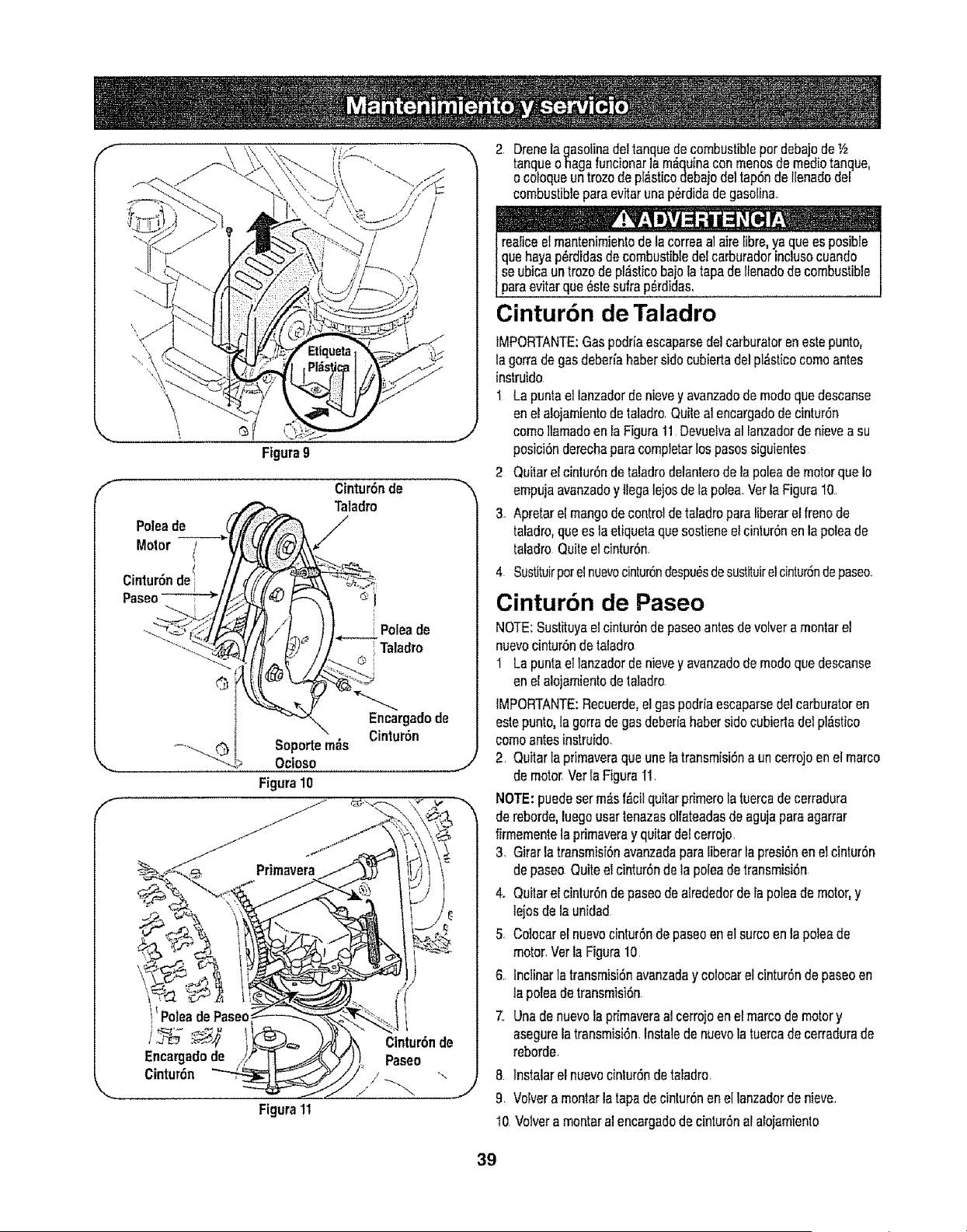
f
x.
f
\
\, @
Figura9
Poleade
Motor
Cintur6ndel
Paseo-_
Cintur6nde
Taladro
Poleade
Taladro
Soportem_s
Ocioso
Figura10
Encargadode
Cintur6n
J
Encargadode
Cintur6n
Figura11
J
2 Drene[agasolinedeltanquedecombustiblepot debajode "_
tanqueohaga funcionarla m_quinaconmenosdemediotanque,
ocoloqueuntrozode pi_sticodebajodeltap6nde IIenadode[
combustiblepareevitarunap_rdidadegasoline.
! ..........,
reaiiceelmantenimienlode la correaalaire[ibre,ya quees posible
quehayap_rdidasde combustibledelcarburadorinclusocuando
se ubicaun trozode pl_sticobajolatapade lienadode combustible
pareevitarque_stesufrap_rdidas.
Cintur6n de Taladro
IMPORTANTE:Gaspodr[aescaparsedelcarburetorenestepunto,
lagorrade gasdeberiahabersidocubiedadelpl_sticocomoantes
instruido
1 La puntaellanzadorde nievey avanzadode modoquedescanse
enelalojamientodetaladro.Quiteal encargadodecintur6n
comoIIamadoen ia Figuretl DevuelvaalIanzadorde nievea su
posici6nderechaparecompletarlospesossiguientes
2 Quitarelcintur6ndetaladrodeianterode tapoleademotorqueIo
empujaavanzadoy liegalejosde[apotea.VerlaFiguretO.
3. Apretarel mangode controlde taIadroparaliberare[frenode
taladro,queesla etiquetaquesostieneel cintur6nen la poleade
taladroQuiteelcintur6n.
4 Sustituirpotelnuevocintur6ndespu_sdesustituirelcintur6ndepaseo.
Cinturbn de Paseo
NOTE:Sustituyaelcintur6nde paseoantesde volvera montarel
nuevocintur6ndetaladro
I La puntaellanzadordenievey avanzadode modoquedescanse
enelalojamientodetaladro
IMPORTANTE:Recuerde,elgaspodriaescaparsedelcarburetoren
estepunto,Iagorradegasdeberiahabersidocubierladelpl,'Jstico
comoantesinatruido.
2. Quitarla pdmaveraque uneia trensmisi6na un cerrojoenel marco
demotorrVerIaFigura11.
NOTE:puedeserm_sf,_cilquitarprimeroiatuercade cerradura
de reborde,luegousartenazasolfateadasde agujapareagarrar
firmementelaprimaveray quitardeleerrojo.
3. Girarla transmisi6navanzadapareIiberarla presi6nen el cintur6n
depaseo Quiteel cintur6nde la poleadetransmisi6n
4. Quilare[cintur6ndepaseodealrededorde[apoleademotor,y
lejosde launidad
5 Coloearel nuevoc[ntur6ndepaseoen el surcoen la poleade
motor.Vetla Figure10
6 lnctinarla transmisi6navanzaday colocarel cintur6ndepaseoen
lapoleadetransmisi6n
7. Unadenuevola pdmaveraal eerrojoen elmarcode motory
asegureIatransmisi6n.Instalede nuevola tuercade cerradurade
reborde.
8 [nstalarel nuevocinlur6nde taladro
9. VoIvera montarla tapedecinlur6nenel lanzadordenieve.
t0 Votvera montaral encargadodecintur6nalalojamiento
39
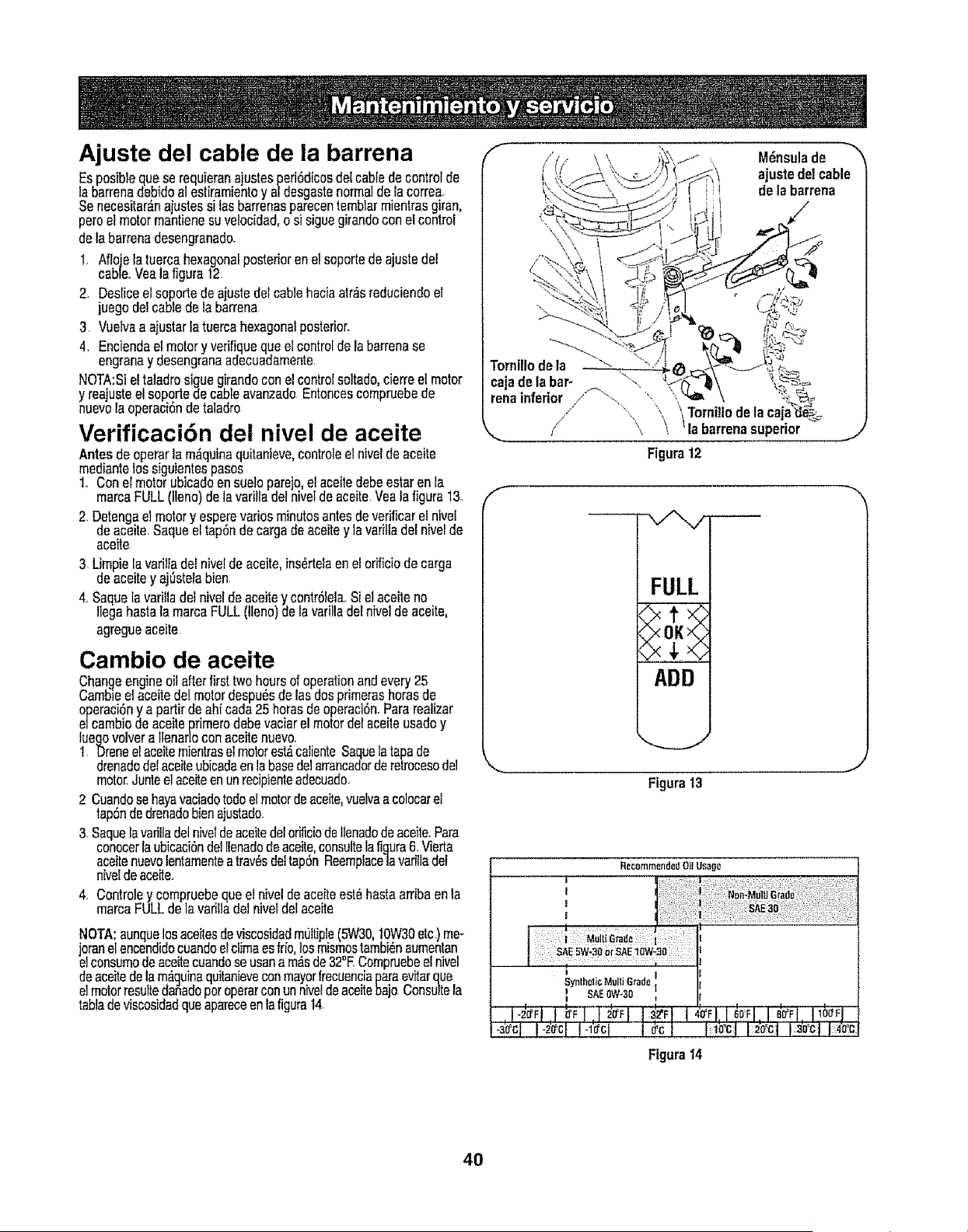
Ajuste del cable de ia barrena
Esposiblequase requieranajustesperiSdicosdel cabledecontrolde
la barrenadebidoai estiramientoy afdesgastenormalde la correa
Senecesitar_.najustessi lasbarrenasparecentemblarmientrasgiran,
peteelmotormantienesu velocidad,esi siguegirandoconel control
delabarrenadesengranadoo
t.. Aflojela tuercahexagonalposteriorenelsoportedeajustedel
cable..Vealafigurat2.
2.. Desliceel soportede ajustedelcablehaciaatr_sreduciendoel
juegodelcablede labarrena
3 Vuelvaa ajustartatuercahexagonalposterior.
4. Enciendael motory verifiquequael controlde la barrenase
engranay desengranaadecuadamente.
NOTA:Sieltaladrosiguegirandocon elcontrolsoitado,cierreel motor
y reajusteel soportedecableavanzadoEntoncescompruebede
nuevola operaci6nde taladro
Verificaci6n del nivel de aceite
Antesdeoperarla m_quinaquitanieve,controleelnivelde aceite
mediantelossiguientespasos
1o Conelmotorubicadoensue!oparejo,el aceitedebeestaren Ea
marcaFULL(llano)delavarilladel niveldeaceite.Vealafigura13,
2, Detengaelmotory esperevariesminutesantesdeverificarelnivel
deaceitaSaqueeltap6ndecargade aceitey la varilladelnivelde
aceite
3 Limpiela variltade!niveldeaceite,ins_rtelaenelorificiodecarga
deaceitey aj0stelabien.
4, Saquetavarillade!niveldeaceitey contr6lela.Sielaceiteno
Ilegahastala marcaFULL(tleno)de la varilladel nivetde aceite,
agregueaceita
Gamble de aceite
Changeengineoilafterfirsttwohoursofoperationandevery25
Cambteelaceitedelmotordespu6sde lasdosprimerashorasde
operaci6ny a partirde ahfcada25 horasde operaci6n_Pararealizar
e/cambiodeaceiteprimatedebevaciarel motordel aceileusadoy
luegovolverallenarloconaceitenuevo..
1 Droneel aceitemienlraselmotorest_calienteSaquelatapade
drenadodelaceiteubicadaenlabasedelarrancadorderetrocesodel
motorJuntoelaceiteenunrecipienteadecuade.
2 Cuandosehayavaciadorodeel motorde aceite,vuelvaacolocarel
tap6ndedrenadobienajustado.
3. Saquelavarilladelniveldeaceitedelorificiode!Ienadodeaceile.Para
conocerlaubicaci6ndel[{enadodeaeeite,consultela figura6, Vierta
aceitenuevolentamentea tray,sde!tap6nReemplace|avarillaclef
niveldeaceite.
4.. Controley compruebequael niveldeaceiteest0hastaarribaenla
marcaFULLdela varifladelniveldelaceite
NOTA:aunquelosaceitesdeviscosidadm01tiple(5W30,!0W30etc) me-
joranelencendidocuandoelclimaesfrio,losmismostambi_naumentan
etconsumedeaeeitecuandoseusana m_sde32°ECompruebeelnivel
deaceitedelam_quinaquitanieveconmayorfrecuenciaparaevitarqua
etmotorresuttedafadoperoperarconunnivetdeaceitebajo Consultela
tabtadeviscosidadquaapareceenla figura14
f
\
M_nsulade -"_
ajustedelcable
de labarrena
Tornillode la _-.
cajade la bar- \..
renainferior / "_-_. '_ \
\ Tomi!lode la
/ _\ \ 'la barrenasuperior
Figura12
F
J
FULL
ADD
,,,..,.__..j
\
Figura13
R_commendadOil Usag_
T i
t I
t I
J I
:SAE 5W-30or SAE 10W-30
,SyntheticMulli GradelI
t SAEOW*30
i-3'a'cl I-2'_cI I-I'¢cI I _cl iioOi i_ool I_o_]_
Figura 14
4O
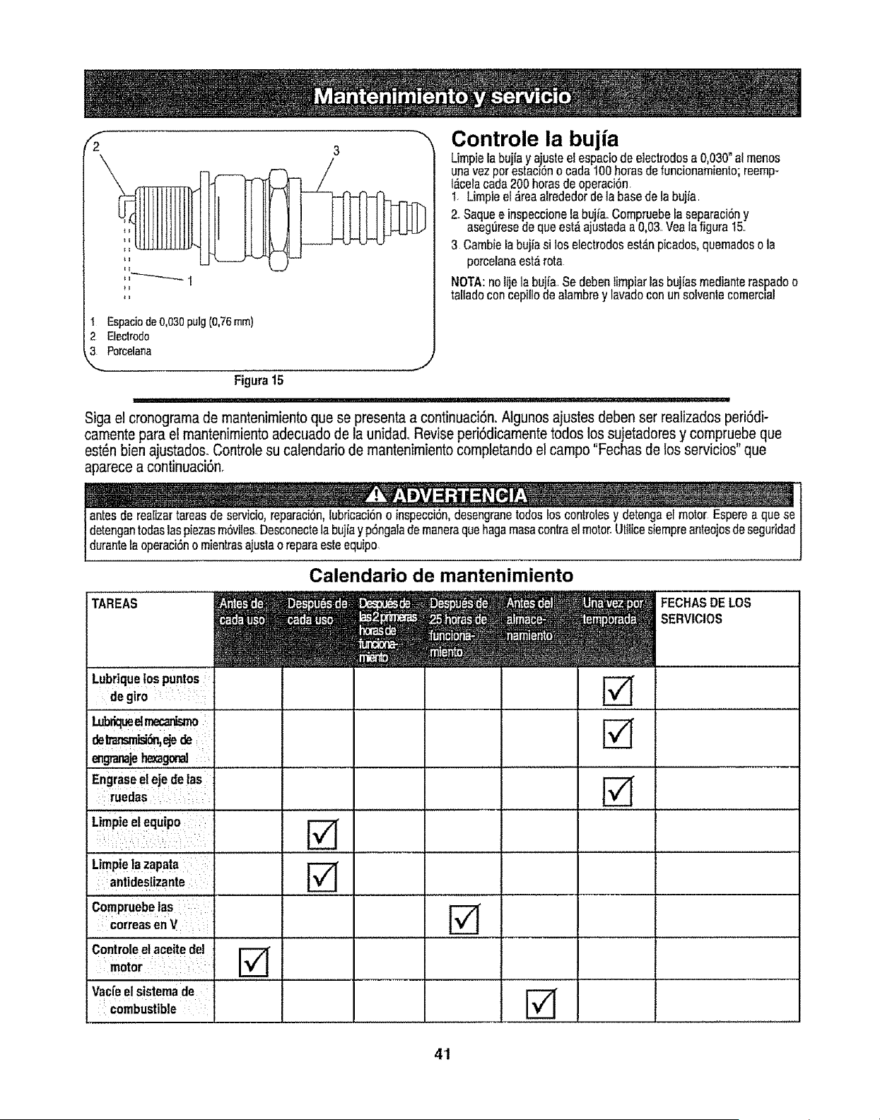
I Espacio de 0,030 pulg (0,76 ram)
2 Eleclrodo
3 Porcelarla
Controle la buj a
Limpielabuj{ay aiusteelespaciodee]ectrodosa 0,030° almenos
unavezporestactSnocada100horasde funcionamienlo;reemp-
l,_celacada200 horasdeoperaci6nr
I Limpieel ,_reaarrededorde la basede la bujfa
2. SaqueeinspeccioneEabujia..Compruebefaseparaci6ny
aseg_resedequeest_ajustadaa 0,03.Veala figura15.
3 Cambielabujiasi los electrodosest_npicados,quemadoso la
porceranaest_rota
NOTA:nolijela buia. Se debenlimpiarlasbuj[asmedianteraspadoo
tal adoconcep o de a ambrey [avadoconun so ventecomercial
J
Figura15
Sigael cronogramade mantenimientoque se presentaa continuaci6n.Atgunosajustes debenset realizadosperi6di-
camenteparaet mantenimientoadecuadode la unidad,Reviseperi6dicamentetodos lossujetadoresy compruebeque
est_nbienajustados.Controlesu calendariode mantenimientocompletandoelcampo"Fechasde los servicios"que
aparecea continuaci6n_
antesderealizartareasde servieio,reparaci6n,1ubr_caci6no inspecci6n,desengranetodoslos controlesy detengael motor Esperea que se
detengantodaslaspiezasm6viles.Desconectela bujiay pSngalademaneraquehagamasacontrael motor,Utiticesiempreanteojosdeseguridad
durante_aoperaci6no mientrasajuslao reparaesteequipo
Calendario de mantenimiento
TAREAS FECHAS DE LOS
SERVICIOS
Lubriquelos punt0s I
degiro I
Lubr_rnecanLu_
de_,e_ de
engranajehexagor_
Engraseel ejetie las
ruedas
',o.lee,o.u,.o1
Limpiela zapata ]
antideslzante : l
Compruebelas l
correasen V 1
Controleel aceitedel ]
motor ]
Vac[eel sistemade t
:combustible !
41
Sinosevaa utilizaelequipodurante30 aliaso m_s,o si eselfinalde]atemporadadenieveyyanoexistsposibiiidaddequanieve,esnecesario
almacer=aretequipodemar=eraadecuadaSigalasinstruccionesdeafmacenamientoquaseindicanacont[nuaci6nparagarantizarel rendimiento
m_imo clela m_quir=aquitanievedurantemuchosafios
PREPARAClON DEL MOTOR
Almacenaje a Corto plazo
Esimportanteevilarqueduranteel almacenamientoseformendep6si-
tosdegomaen [aspiezasesencialesdel sistemade combustibleclel
motorcomo,potejemplo,en e]carburador,el fi[trode combustible,ia
manguerade combustibleo el dep6sito
Elusodeestabilizadoresdecombustible(comoSTA-BIL)es unaat-
ternativaaceptableparaminimizarla formaci6ndedep6sitosde goma
decombustibleduranteel almacenamientooAgregueel estabilizador
ala gaso[inaquase encuentraen el dep6sitodecombustibleo en
elrecipientsdeatmacenamientoRespetesiemprela proporci6nde
mezcladoque figuraen el recipientedelestabilizador.Pongaet motor
enmarchaportomanes10minutosdespu_sdeagregarel estabiliza-
dorparapermitirlellegaral carburador.Nodreneel carburadorsi est&
utilizanctounestabitizadordecombustible
PREPARACION DE LA M._QUINA QUITANIEVE
1. Cuandoalmacenefa m_quinaquitanieveenungalp6nde
dep6sitomet_licoo conpocavontilaci6n,ter=gaespecialcuidado
dereatizarleur=tratamientoanti-oxidantealequipo..Useaceite
]igeroosilic6npararecubrirel equipo,especialmentelas
cadenas,losresortes,ioscojir=stesy Ioscables.
2 Eliminetodoel polvodelexteriorde]motory delequipo
3 SigaIasrecomendacionesde tubricaci6nenla secci6nde
mantenimientodeestemanual
4 Almaceneel equipoer=un _readespejaday seca.
Nuncaalmaoenelam_quinaquitanieveconcombustibleene]
tanqueen unespaciocerradoo en _reasconpocaventilaciSn,
dondelosgasesdelcombustiblepuedanalcanzarelfuego,chispas
o unatuzpiiotocomolaquetienenalgunoshomos,calentadoresde
agua,secadoresde ropao a gLinotrod spostivo a gas.
Atoscombustiblescon mezctade alcohol(quese ltamangasohol,
]oqueutitizanetanolo metanol)puedenatraer[ahumedad,io qua
]conducea la separaci6ny formaci6nde _cidosduranteel almace-
Inamiento_Elgasacfdicopuededafiarel sistamade[combustiblede
[un motorduranlee!a]macenamientodelmismo.
Almacenaje a Largo plazo
Paraevitarprob_emasconel motor,e! sistemadel combustibledebe
servaciadoantesdealmacenarlam&quinadurante30 diaso rn_s.
o ! .,a ; _ _,
Elcombustiblequese dejeenelmotorse deterioracuandoelclima
esc_ do y causagravesprobemasde encenddon J
1 Pongael motoren marchahastavaciarel dep6sitodecom-
bustibley hastaquaelmotorse detengadebidoa la faltade
combustible.
Nuncauseel motoro e]carburadorquelimpiaproductosenel
dep6stodecombustbe o e daSopermanentspuedeocurrr j
Retirelabujiayvierta(1)onzade aceiteparamotora tray,sdet
orificiodeta bujiay haciaetinteriordei cilindro Cubrael orificio
delabujiacon untrapoy pongael motoren marchavariasraces
paradistribuirel aceite.Reempiacelabujia
42
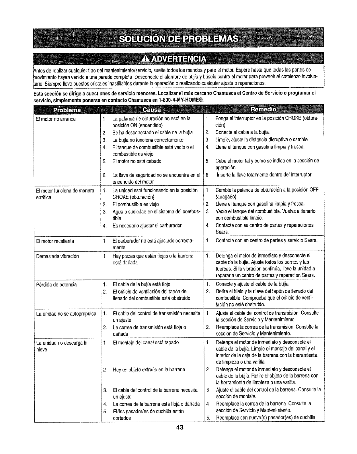
ristatesinastiltablesdurantela operaci6no reafizandocualquierajusteo reparaciones.
Estasecci6n sedidgeacuestionesdeserviciomenoresoLocalizarel m_scercanoChamuscael Centrode Servicioo programarel
servicio,simptementeponerseen contactoChamuscaen1-800-4-MY-HOME®.
J
Elmotornoarranca ! La'palancade'obturacOnno'estAen la
1
Elmotorfuncionademanera
err_tica
Elmotorrecalienta
Demasiadavibraci6n
P_rdida de polencia
Launidadnose autopropulsa
+Launidadno descargala
nieve
posici6nON(encendido)
2 Seha desconectadoel cablede labujia
4 La bujfanofuncionacorrectamente
, EItanquedecombustibleest_vacfoo el
combustibleesviejo
5 El motorno est_cebado
6 La Ilavede seguridadnose encuentraen el
encendidodetmotor
I. La unidadest_funcionandoen ia posici6n
CHOKE(obturaci6n)
2+ Etcombustiblees viejo
3 Aguao suciedadenelsistemade]combos-
tible
4. Esnecesarioajustarelcarburador
I Elcarburadornoest,,ajustadocorrecta-
mente
1 Haypiezasqueest_nffojasolabarrena
est#,dafiada
1. E1cabledela bujfaest_flojo
2. El orMciode ventilaci6ndeltap6nde
Ilenadodelcombustibleest,.obstruido
1. Elcabledel controlde transmisi6nnecesita
unajuste
2. Lacorreade transmisi6nest_flojao
dafiada
I El montajede!canalest_tapado
2 Hayun objetoextrafioenlabarrena
3 Etcabledelcontroldetabarrenanecesita
unajuste
4. Lacorreadelabarrenaest_flojaodaSada
5. Ettlospasadodesde cuchillaest_n
cortados
2,
&
4
5
6
1.
2.
3
4+
!
1,
PongaelinterruptorenlaposicOnCHOKE(obtura-
ci6n).
Conecteel cableala bujia
Limpie,ajustetadistanciadisruptivao cambie.
LIeneettanquecongasotinalimpiay fresca.
Cebee+motortal y comoseindicaen la secci6nde
operacibn
Insertelallavetotalmentedentrodelinterruptor,
Cambielapalancadeobturaci6nala posici6nOFF
(apagado)
Ueneel tanquecongasolinalimpiay fresca+
Vacieel tanquedelcombustible,Vuelvaa Ilenado
concombustibleIimpio.
Contacteconsucentrodepartesy reparaciones
Sears.
Contacteconuncentrodepartesy servic+oSears,
Delengae+motorde inmediatoy desconecteel
cablede tabujia.Ajustetodoslospernosy Ias
tuercas,Silavibraci6ncontin{Ja,Ilevelaunidada
reparara un centrodepartesy reparaci6nSears,
1, Conectey ajusteel cabledeIabujfa,
2. Retiree+hieloy lanievedeltap6nde Itenadodel
combustible.Compruebequeel ofificiodeventi+
lacOnno est_obstruido,
t, Ajusteel cabledelcontroldetransmisi6nConsulte
lasecci6ndeServicioy Mantenimiento
2 ReemplaceIacorreade la transmisi6n,Consultela
secci6ndeServicioy Mantenimiento+
1 Detengaetmotorde inmediatoy desconecteel
cablede tabujia.,Limpieel montajedelcanaly el
interiordelacajadelabarrenaconlaherramienta
delimpiezao unavarilla,
2, Detengaelmotordeinmediatoy desconecteel
cablede la bujfa Retireetobjetode labarrenacon
fa herramientadelimpiezao unavari+la
3 Ajusteel cabledelcontroldela barrena,Consultela
secci6ndemontaje,,
4 Reemplacelacorreade ta barrenaConsultela
secci6ndeServicioy Mantenimientoo
5. Reemplaceconnuevo(s)pasador(es)decuchiUa,,.........
43

Get it fixed,
z
at your home or ours!
Your Home
For repair - in your home - of all major brand appliances,
lawn and garden equipment, or heating and cooling systems,
no matter who made it, no matter who sold it!
For the replacement parts, accessories and
owner's manuals that you need to do-it-yourselfo
For Sears professional installation of home appliances
and items like garage door openers and water heaters°
1-800-4-MY-HOME ® (1.,800-469-4663)
Cal! anytime, day or night (U,rS,,A,r and Canada)
www,sears.corn www.sears.ca
For expert home solutions advice: www.managemyhome.com
Our Home
For repair of carry-in items like vacuums, lawn equipment,
and electronics, call or go on-line for the location of your nearest
Sears Parts & Repair Service Center
1-800-488-t222 (US,A) 1-800-469-4663 (Canada)
Call anytime, day or night
www.sears.com www.sears.ca
To purchase a protection agreement on a product serviced by Sears:
1-800-827-6655 (u,s A) t -800-361-6665 (Canada)
Para pedir servicio de reparaci6n
a domicilio, y para ordenar piezas:
1-888-SU-HOGAR ®
(1-888-784-6427)
Au Canada pour service en frangais:
1-800-LE-FOYER Mc
(1-800-533-6937)
wWW,rSears ca
eSIr-S
: • _ • i_ _
TM _M
® Registered Trademark / Trademark I _ Service Mark of Sears Brands, LLC
Marca de F_brfca / Marca de Servicio de Sears Brands, LLC
® Marca Registrada / TM SU
_C Marque de commerce tuo Marque d_pos_e de Sears Brands, LLC
© Sears Brands, LLC


