perator's nual
I:RRFrSMAN+
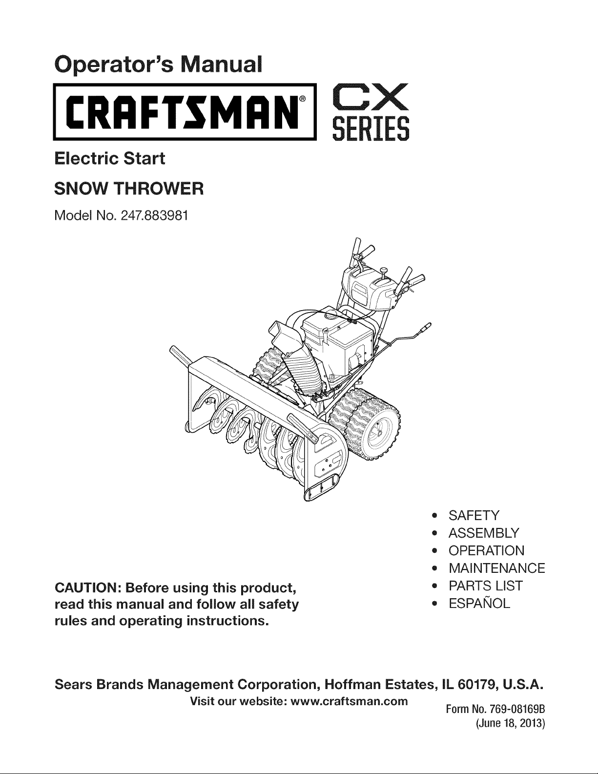
Electric Start
SNOW THROWER
Model No. 247.883981
CX
IES
CAUTION" Before using this product,
read this manual and follow all safety
rules and operating instructions.
,, SAFETY
o ASSEMBLY
OPERATION
MAINTENANCE
PARTS LIST
o ESPANOL
Sears Brands Management Corporation, Hoffman Estates, IL 60179, U.S.A.
Visit our website: www.craftsman.com
Form No. 769-08169B
(June 18, 2013)
Warranty Statement .................................. Page 2
Safe Operation Practices .......................... Page 3
Assembly .................................................. Page 7
Operation .................................................. Page 13
Service and Maintenance ......................... Page 18
Off-Season Storage .................................. Page 26
Troubleshooting ........................................ Page 27
Parts List ................................................... Page 28
Repair Protection Agreement ................... Page 47
Espafiol ..................................................... Page 48
Service Numbers ...................................... Back Cover
CRAFTSMANCXTWOYEAR FULL WARRANTY
FORTWOYEARSfromthe dateof purchase,thisproductis warrantedagainstanydefectsin materialor workmanship.A defective
productwill receivefree repairor replacementif repairis unavailable.
Forwarranty coverage details to obtain free repairor replacement,visitthe web site: www.craftsman.com
Thiswarranty coversONLYdefects in material andworkmanship. Warranty coveragedoes NOTinclude:
• Expendableitemsthatcan wearoutfromnormalusewithinthe warrantyperiod,includingbutnot limitedto augers,augerpaddles,
driftcutters,skidshoes,shaveplate,shearpins,sparkplug,aircleaner,belts,andoil filter.
• Standardmaintenanceservicing,oilchanges,or tune-ups.
Tire replacementor repaircausedby puncturesfrom outsideobjects,such as nails, thorns,stumps,or glass.
• Tireor wheelreplacementor repairresultingfromnormalwear,accident,or improperoperationor maintenance.
• Repairsnecessarybecauseof operatorabuse,includingbut notlimitedto damagecaused byover-speedingthe engine,or from
impactingobjectsthat bendthe frame,auger shaft,etc.
• Repairsnecessarybecauseof operatornegligence,includingbutnot limitedto, electricaland mechanicaldamagecausedby
improperstorage,failureto usethe propergradeandamountof engineoil,or failureto maintainthe equipmentaccordingto the
instructionscontainedinthe operator'smanual.
• Engine(fuel system)cleaningor repairscausedbyfuel determinedto be contaminatedor oxidized(stale). Ingeneral,fuel shouldbe
usedwithin30 daysof its purchasedate.
• Normaldeteriorationandwearof the exteriorfinishes,orproductlabelreplacement.
Thiswarrantyis void if this productisever usedwhileprovidingcommercialservicesor if rentedto anotherperson.
Thiswarrantygivesyou specificlegalrights,andyoumay alsohaveother rightswhichvary from stateto state.
Sears Brands ManagementCorporation, Hoffman Estates, IL 60179
EngineOilType: 5W-30
EngineOilCapacity: 37ounces
FuelCapacity: Approx.5 Quarts
SparkPlug: F6RTC(951-10292)
SparkPlugGap: .020"to .030"
Model Number.................................................................
Serial Number .................................................................
Dateof Purchase.............................................................
Recordthe modelnumber,serialnumber
anddateof purchaseabove
© Sears Brands,LLC
2
Thissymbolpointsout importantsafety instructionswhich, if not
followed, couldendangerthe personalsafetyand/or property of
yourself and others.Readandfollow all instructions inthis manual
beforeattempting to operatethis machine.Failureto complywith these
instructionsmay resultinpersonalinjury.Whenyouseethis symbol, HEED
ITSWARNING!
CALIFORNIA PROPOSITION 65
EngineExhaust,someof its constituents,and certain vehiclecomponents
containor emit chemicalsknownto Stateof Californiato causecancerand
birth defectsor other reproductiveharm.
Thismachinewasbuilt to beoperatedaccordingto thesafeoperation
practicesinthis manual.Aswith anytype of powerequipment,
carelessnessorerror on the part of the operatorcanresultinseriousinjury.
Thismachineiscapableof amputating fingers, hands,toesandfeet and
throwingdebris. Failureto observethefollowing safety instructionscould
resultin seriousinjuryor death.
Your Responsibility--Restrict theuseof this powermachineto
personswho read,understandandfollow the warningsand instructionsin
this manualandon the machine.
SAVETHESEINSTRUCTIONS!
TRAINING
Read,understand,andfollowall instructionsonthemachineandinthe
manual(s)beforeattemptingto assembleandoperate.Failureto dosocan
resultinseriousinjury tothe operatorand/orbystanders.Keepthis manual
inasafeplaceforfutureandregularreferenceandfororderingreplacement
parts.
Befamiliarwith all controlsandtheir properoperation.Knowhowto stop
themachineanddisengagethemquickly.
Neverallowchildrenunder14yearsof ageto operatethis machine.Children
14andovershouldreadandunderstandtheinstructionsandsafeoperation
practicesinthis manualandonthemachineandbetrainedandsupervised
byanadult.
Neverallowadultsto operatethismachinewithout properinstruction.
Thrownobjectscancauseseriouspersonalinjury.Planyoursnow-throwing
patternto avoiddischargeof materialtowardroads,bystandersandthelike.
Keepbystanders,petsandchildrenat least75feetfrom the machinewhileit
isin operation.Stopmachineif anyoneentersthe area.
Exercisecautionto avoidslippingor falling,especiallywhenoperatingin
reverse.
PREPARATION
Thoroughlyinspecttheareawheretheequipmentisto beused.Removeall
doormats,newspapers,sleds,boards,wiresandotherforeignobjects,which
couldbetrippedoveror thrownbythe auger/impeller.
Alwayswearsafetyglassesoreyeshieldsduringoperationandwhile
performinganadjustmentor repairto protectyoureyes.Thrownobjects
whichricochetcancauseseriousinjuryto theeyes.
Donotoperatewithout wearingadequatewinteroutergarments.Donot
wearjewelry,longscarvesorotherlooseclothing,whichcouldbecome
entangledinmovingparts.Wearfootwearwhichwill improvefootingon
slipperysurfaces.
Usea groundedthree-wireextensioncordandreceptacleforall machines
with electricstartengines.
Disengageallcontrolleversbeforestartingtheengine.
Adjustcollectorhousingheightto cleargravelor crushedrocksurfaces.
Neverattemptto makeanyadjustmentswhile engineisrunning,except
wherespecificallyrecommendedintheoperator'smanual.
Letengineandmachineadjustto outdoortemperaturebeforestartingto
clearsnow.
Safe Handling of Gasoline:
Toavoid personalinjuryor property damageuseextreme carein handling
gasoline.Gasolineisextremely flammable andthe vaporsareexplosive.
Seriouspersonalinjurycan occurwhengasolineis spilledon yourselfor your
clotheswhichcanignite. Washyour skinandchangeclothesimmediately.
Useonlyanapprovedgasolinecontainer.
Neverfill containersinsidea vehicleorona truckortrailerbedwitha plastic
liner.Alwaysplacecontainersonthegroundawayfrom yourvehiclebefore
filling.
Whenpractical,removegas-poweredequipmentfrom thetruckor
trailer andrefuelit ontheground.Ifthisis notpossible,thenrefuelsuch
equipmenton atrailerwith aportablecontainer,ratherthanfrom agasoline
dispensernozzle.
Keepthe nozzleincontactwith the rimofthefuel tankorcontaineropening
at alltimesuntil fuelingiscomplete.Donot usea nozzlelock-opendevice.
Extinguishall cigarettes,cigars,pipesandothersourcesof ignition.
Neverfuel machineindoors.
Neverremovegascaporaddfuelwhilethe engineishot or running.Allow
engineto coolat leasttwo minutesbeforerefueling.
Neveroverfill fueltank.Filltankto nomorethan1/2inchbelowbottomof
filler neckto allowspacefor fuelexpansion.
Replacegasolinecapandtightensecurely.
Ifgasolineisspilled,wipeit offthe engineandequipment.Moveunitto
anotherarea.Wait.5minutesbeforestartingtheengine.
Toreducefirehazards,keepmachinefreeofgrass,leaves,orotherdebris
build-up.Cleanupoilorfuelspillageandremoveanyfuelsoakeddebris.
Neverstorethemachineorfuelcontainerinsidewherethereisanopen
flame,sparkorpilotlightasonawaterheater,spaceheater,furnace,clothes
dryerorothergasappliances.
OPERATION
Donotput handsorfeetnearrotatingparts,intheauger/impellerhousing
orchuteassembly.Contactwith the rotatingpartscanamputatehandsand
feet.
Theauger/impellercontrolleverisasafetydevice.Neverbypassits
operation.Doingsomakesthemachineunsafeandmaycausepersonal
injury.
Thecontrolleversmustoperateeasilyin bothdirectionsandautomatically
returnto thedisengagedpositionwhenreleased.
Neveroperatewith amissingordamagedchuteassembly.Keepallsafety
devicesinplaceandworking.
Neverrunanengineindoorsor inapoorlyventilatedarea.Engineexhaust
containscarbonmonoxide,anodorlessanddeadlygas.
Donotoperatemachinewhileundertheinfluenceof alcoholordrugs.
Mufflerandenginebecomehot andcancauseaburn.Donot touch.Keep
childrenaway.
Exerciseextremecautionwhenoperatingonorcrossinggravelsurfaces.Stay
alertforhiddenhazardsortraffic.
Exercisecautionwhenchangingdirectionandwhileoperatingonslopes.Do
notoperateon steepslopes.
Planyoursnow-throwingpatternto avoiddischargetowardswindows,
walls,carsetc.Thus,avoidingpossiblepropertydamageorpersonalinjury
causedbyaricochet.
Neverdirectdischargeat children,bystandersandpetsor allowanyonein
front of themachine.
Donotoverloadmachinecapacitybyattemptingto clearsnowat toofastof
arate.
Neveroperatethismachinewithoutgoodvisibilityorlight.Alwaysbesureof
yourfootingandkeepafirm holdon thehandles.Walk,neverrun.
Disengagepowerto the auger/impellerwhentransportingornotin use.
Neveroperatemachineat hightransportspeedsonslipperysurfaces.Look
downandbehindandusecarewhenbackingup.
If themachineshouldstartto vibrateabnormally,stopthe engine,
disconnectthe sparkplugwire andgroundit againstthe engine.Inspect
thoroughlyfordamage.Repairanydamagebeforestartingandoperating.
Disengageallcontrolleversandstopenginebeforeyouleavetheoperating
position(behindthehandles).Waituntil theauger/impellercomesto
acompletestopbeforeuncloggingthe chuteassembly,makingany
adjustments,orinspections.
Neverput yourhandin thedischargeor collectoropenings.Donot unclog
chuteassemblywhileengineis running.Shutoff engineandremainbehind
handlesuntil all movingpartshavestoppedbeforeunclogging.
Useonlyattachmentsandaccessoriesapprovedbythemanufacturer(e.g.
wheelweights,tirechains,cabsetc.).
Whenstartingengine,pull cordslowlyuntil resistanceisfelt, thenpull
rapidly.Rapidretractionofstartercord(kickback)will pullhandandarm
towardenginefasterthanyoucanletgo.Brokenbones,fractures,bruisesor
sprainscouldresult.
Ifsituationsoccurwhicharenotcoveredinthismanual,usecareandgood
judgment.
CLEARING A CLOGGED DISCHARGE CHUTE
Handcontactwith therotatingimpellerinsidethedischargechuteisthe most
commoncauseof injuryassociatedwith snowthrowers.Neveruseyourhandto
cleanout thedischargechute.
Toclearthechute:
a. SHUTTHEENGINEOFF!
b. Wait 10secondsto besurethe impellerbladeshavestopped
rotating.
c. Alwaysuseaclean-outtool,notyourhands.
MAINTENANCE & STORAGE
Nevertamperwith safetydevices.Checktheirproperoperationregularly.
Referto the maintenanceandadjustmentsectionsof thismanual.
Beforecleaning,repairing,or inspectingmachinedisengageallcontrol
leversandstopthe engine.Waituntil theauger/impellercometo acomplete
stop.Disconnectthesparkplugwire andgroundagainstthe engineto
preventunintendedstarting.
Checkboltsandscrewsforpropertightnessat frequentintervalsto keepthe
machineinsafeworkingcondition.Also,visuallyinspectmachineforany
damage.
Donotchangetheenginegovernorsettingor over-speedtheengine.The
governorcontrolsthemaximumsafeoperatingspeedof theengine.
Snowthrowershaveplatesandskidshoesaresubjectto wearanddamage.
Foryoursafetyprotection,frequentlycheckall componentsandreplace
with originalequipmentmanufacturer's(OEM)partsonlyaslistedinthe
Partspagesofthisoperator'smanual.Useof partswhichdonot meetthe
originalequipmentspecificationsmayleadto improperperformanceand
compromisesafety!
Checkcontrolleversperiodicallyto verifytheyengageanddisengage
properlyandadjust,ifnecessary.Referto theadjustmentsectioninthis
operator'smanualfor instructions.
Maintainorreplacesafetyandinstructionlabels,asnecessary.
Observeproperdisposallawsandregulationsforgas,oil,etc.to protectthe
environment.
Priorto storing,runmachineafewminutesto clearsnowfrommachineand
preventfreezeupof auger/impeller.
Neverstorethemachineorfuelcontainerinsidewherethereisanopen
flame,sparkor pilot light suchasa waterheater,furnace,clothesdryeretc.
Alwaysreferto theoperator'smanualforproperinstructionsonoff-season
storage.
4
Checkfuelline,tank,cap,andfittingsfrequentlyfor cracksor leaks.Replace
if necessary.
Donotcrankenginewith sparkplugremoved.
Accordingto theConsumerProductsSafetyCommission(CPSC)andthe
U.S.EnvironmentalProtectionAgency(EPA),thisproducthasan Average
Useful Life of seven(7)years,or60hoursofoperation.Atthe endof
theAverage Useful Life havethemachineinspectedannuallybyan
authorizedservicedealerto ensurethat all mechanicalandsafetysystems
areworkingproperlyandnotwornexcessively.Failureto dosocanresultin
accidents,injuriesor death.
DO NOT MODIFY ENGINE
Toavoidseriousinjuryordeath, do notmodifyengineinanyway. Tampering
with the governorsetting canlead to arunawayengineandcauseit to
operateat unsafespeeds.Nevertamperwith factorysetting of engine
governor.
NOTICE REGARDING EMiSSiONS
Engineswhich are certifiedto complywith Californiaandfederal EPA
emissionregulationsfor SORE(SmallOff RoadEquipment)arecertified
to operateon regularunleadedgasoline,and mayincludethe following
emissioncontrolsystems:EngineModification (EM),OxidizingCatalyst(0C),
SecondaryAir injection(SAI)andThreeWayCatalyst(TWC)if soequipped.
SPARK ARRESTOR
e
Thismachineisequippedwith an internalcombustionengine andshould
not be usedonornearanyunimprovedforest-covered,brushcoveredor
grass-coveredland unlessthe engine'sexhaustsystemis equippedwith a
sparkarrestormeeting applicable localor state laws(if any).
Ira sparkarrestoris used,it shouldbe maintainedin effective working order
bythe operator. In theState of Californiathe aboveisrequired bylaw (Section
4442of the CaliforniaPublicResourcesCode).Otherstates mayhavesimilar
laws.Federallaws apply on federal lands.
Asparkarrestorfor the muffler is availablethroughyour nearestSearsParts
andRepairServiceCenter.

SAFETY SYMBOLS
Thispage depicts and describes safety symbols that may appear on this product. Read, understand, and follow all instructions on the machine before
attempting to assemble and operate.
READ THE OPERATOR'S MANUAL(S)
Read, understand, and follow all instructions in the manual(s) before attempting to assemble and
operate
WARNING-- ROTATING BLADES
Keep hands out of inlet and discharge openings while machine is running. There are rotating blades
inside
WARNING-- ROTATING BLADES
Keep hands out of inlet and discharge openings while machine is running. There are rotating blades
inside
WARNING-- ROTATING AUGER
Do not put hands or feet near rotating parts, in the auger/impeller housing or chute assembly.
Contact with the rotating parts can amputate hands and feet.
WARNING--THROWN OBJECTS
This machine may pick up and throw and objects which can cause serious personal injury.
WARNING--GASOLINE IS FLAMMABLE
Allow the engine to cool at least two minutes before refueling.
WARNING-- CARBON MONOXIDE
Never run an engine indoors or in a poorly ventilated area. Engine exhaust contains carbon
monoxide, an odorless and deadly gas.
WARNING-- ELECTRICAL SHOCK
Do not use the engine's electric starter in the rain
WARNING-- HOT SURFACE
Engine parts, especially the muffler, become extremely hot during operation. Allow engine and
muffler to cool before touching.
WARNING: Your Responsibility--Restrict the use of this power machine to persons who read, understand and follow
the warnings and instructions in this manual and on the machine.
SAVETHESEiNSTRUCTIONS!
6
NOTE:Referencesto rightor leftsideofthesnowthroweraredeterminedfrom the
operatingpositionlookingforwardto thefrontofthe machine.
RemovingFrom(:rate
1. Removescrewsfromthebottomof the cratesecuringthe sides,andendsof
theshippingcrate.
2. Lift offthetopoff of the crateandsetout of thewayof theassemblyarea.
3. Removeanddiscardplasticbagthat coversunit.
4. Removeanyloosepartsincludedwith unit (e.g.,Operator'sManual,etc.).
5. Pushdownon thelowerhandleandpull unit backoutofcrate.
6. Makecertainthe cratehasbeencompletelyemptiedbeforediscardingit.
Assembly
a.
b.
Makecertainthe springsat thelowerendof theaugeranddrive
cablesaresecurelyhookedintotheir respectiveactuator
bracketsbeforepivotingthe handleupward.Referto Figure14.
Placethespeedselectorshift leverin theF6position.
Cutthecabletiesecuringthetwo piecechutecrankto the
lowerhandle.Thecabletie is usedforshippingpurposes.
Removethe upperwingknobandcarriagebolt fromeach
sideofthe lowerhandle.Pullupon upperhandleasshown
in Figure1.Alignupperhandlewith thelowerhandle.Again,
makecertainthespringsat thelowerendof theaugerand
drivecablesaresecurelyhookedinto theirrespective
actuatorbrackets.Also,removeanyrubberbandssecuring
thecablesto thewing nuts.
Figure1
2. a. Securethesupportbracket,upperhandleandlowerhandlewith the
two wingknobsandcarriageboltsremovedearlier.SeeFigure2.
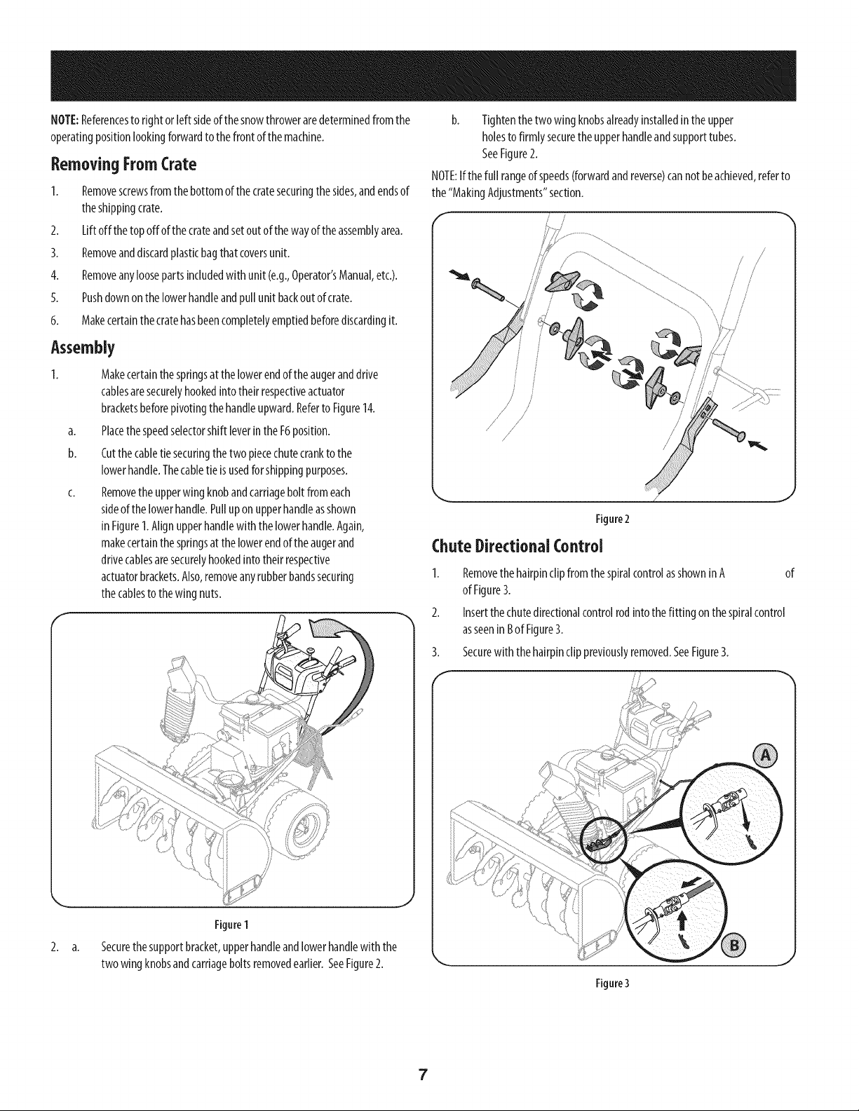
b. Tightenthetwowing knobsalreadyinstalledin theupper
holesto firmly securetheupperhandleandsupporttubes.
SeeFigure2.
NOTE:If the full rangeof speeds(forwardandreverse)cannotbeachieved,referto
the"MakingAdjustments"section.
!
3.
F"
Removethe hairpinclip fromthespiralcontrolasshowninA of
ofFigure3.
Insertthe chutedirectionalcontrolrodinto the fitting on the spiralcontrol
asseenin BofFigure3.
Securewiththehairpinclip previouslyremoved.SeeFigure3.
Figure3
7

ChuteAssembly
Removelock nutsandscrewssecuringoneof the flangekeepersto thechute
assembly.Loosenthe fastenersof theothertwo flangekeepers.SeeFigure
4.
2. Placechuteassemblyontochutebaseasshownin Figure5.Makesurethat
thechutenotchesengagewith thespiralendofchutedirectionalcontrol,
andthe two flangekeepersarebeneaththe flangeonthechutebase.
3. Secureflangekeeperremovedearlierwith locknutsandscrews.Tighten
downnutssecuringtheothertwo flangekeepers.SeeFigure4.
Set-Lip
ChuteClean-OutTool
Neveruseyourhandsto clearacloggedchuteassembly.Shutoffengine and
remainbehindhandlesuntilall movingpartshavestoppedbeforeusingthe
clean-outtool to clearthe chuteassembly.
Achuteclean-outtool isfastenedto the topof the augerhousingwitha mounting
clip.SeeFigure6. Thetool is designedto clearachuteassemblyof iceandsnow.
Thisitem isfastenedwith acabletie at thefactoryforshippingpurposes.Youmay
cut thecabletie at thistime.
Figure4
4. If notalreadydone,slipthecablesthat runfromthe handlepanelto the
dischargechuteinto thecableguideon topof theengine.SeeFigure5.
5. Normallythecabletiesholdingthesteeringcablesagainstthehandleare
looselyinstalledon eachsideof the lowerhandleatthe factory.Pullthe
cabletiestight to secure.Cutthe excessfrom the endsof cableties.
\
Figure5
!, //
Clean-outTool
/
i/
Figure6
J
Drift Cutters
Thesnowthrowerdrift cuttersaremountedinvertedat thefactoryforshipping
purposes.
1. Removethe fourwingknobs(twooneachside)andcarriagebolts.Place
drift cutterin uprightpositionandre-secure.SeeFigure7.
i i
J
Figure7
8
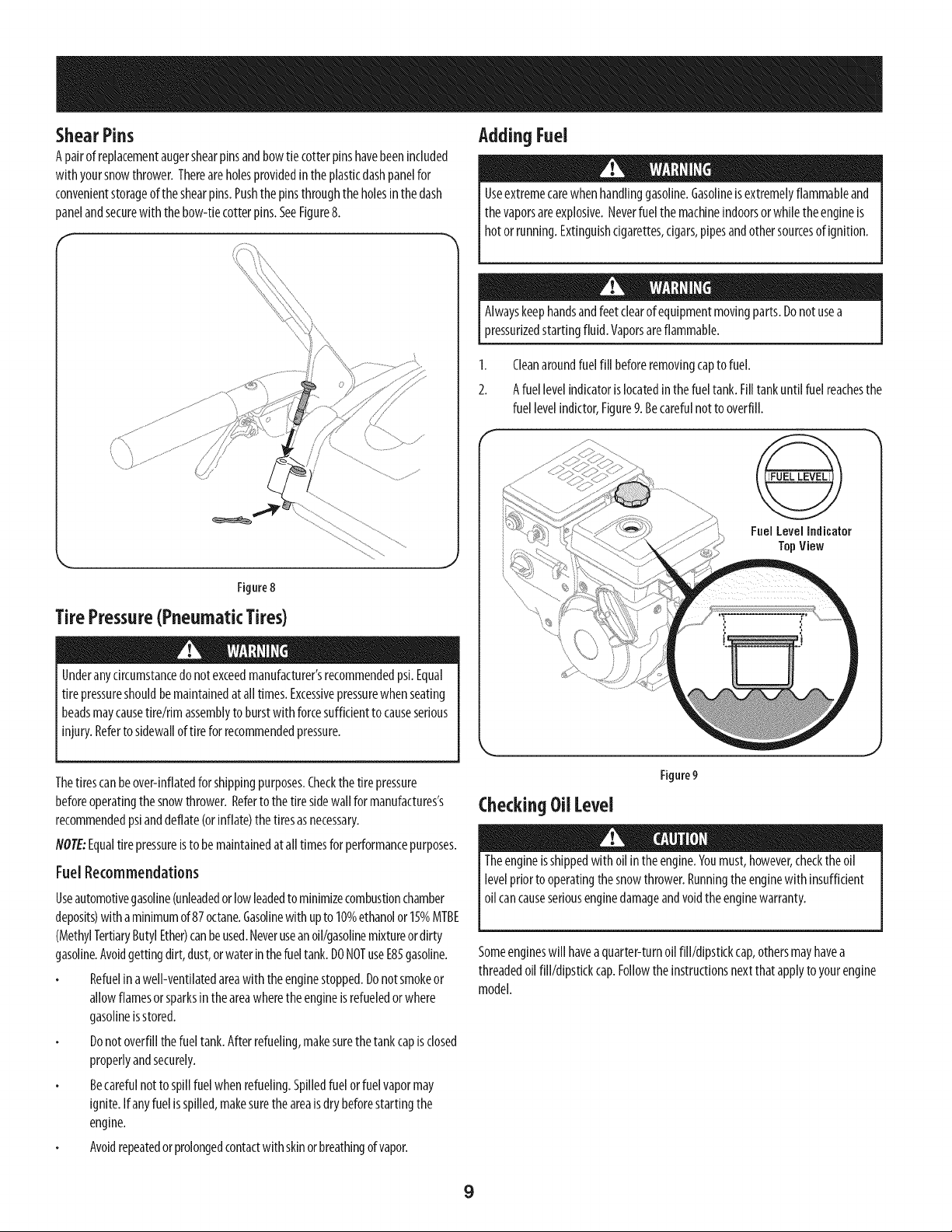
ShearPins
A pairof replacementaugershearpinsandbowtiecotter pinshavebeenincluded
with yoursnowthrower.Thereareholesprovidedin theplasticdashpanelfor
convenientstorageof theshearpins.Pushthepinsthroughthe holesinthedash
panelandsecurewith thebow-tiecotterpins.SeeFigure8.
Figure8
Tire Pressure(Pneumatic Tires)
Underanycircumstancedo notexceedmanufacturer'srecommendedpsi.Equal
tire pressureshouldbemaintainedatall times.Excessivepressurewhenseating
beadsmaycausetire/rim assemblyto burstwith forcesufficientto causeserious
injury.Referto sidewalloftire forrecommendedpressure.
AddingFuel
Useextremecarewhenhandlinggasoline.Gasolineisextremelyflammableand
thevaporsareexplosive.Neverfuel themachineindoorsor whiletheengineis
hotorrunning.Extinguishcigarettes,cigars,pipesandothersourcesof ignition.
Alwayskeephandsandfeetclearof equipmentmovingparts.Donot usea
pressurizedstartingfluid.Vaporsareflammable.
1. Cleanaroundfuelfill beforeremovingcapto fuel.
2. Afuel levelindicatoris locatedin thefuel tank.Filltankuntilfuel reachesthe
fuel levelindictor,Figure9. Becarefulnot to overfill.
@
Fnel LevelIndicator
TopView
Thetirescanbeover-inflatedforshippingpurposes.Checkthetirepressure
beforeoperatingthesnowthrower. Referto thetiresidewall for manufactures's
recommendedpsianddeflate(orinflate)thetiresasnecessary.
NOTE:Equaltire pressureisto be maintainedatall timesfor performancepurposes.
FuelRecommendations
Useautomotivegasoline(unleadedor low leadedto minimizecombustionchamber
deposits)with aminimumof87octane.Gasolinewith upto 10%ethanolor15%MTBE
(MethylTertiaryButylEther)canbeused.Neveruseanoil/gasolinemixtureor dirty
gasoline.Avoidgettingdirt,dust,orwaterinthefueltank.DONOTuseE85gasoline.
Refuelinawell-ventilatedareawiththeenginestopped.Donotsmokeor
allowflamesor sparksintheareawheretheengineis refueledorwhere
gasolineisstored.
Donotoverfillthefueltank.Afterrefueling,makesurethetankcapisclosed
properlyandsecurely.
Becarefulnot to spillfuel whenrefueling.Spilledfuel orfuelvapormay
ignite.If anyfuel isspilled,makesurethe areais dry beforestartingthe
engine.
Avoidrepeatedorprolongedcontactwith skinor breathingofvapor.
Figure9
CheckingOil Level
Theengineisshippedwith oil intheengine.Youmust,however,checktheoil
levelpriorto operatingthe snowthrower.Runningtheenginewith insufficient
oil cancauseseriousenginedamageandvoidtheenginewarranty.
Someengineswill havea quarter-turnoil fill/dipstickcap,othersmayhavea
threadedoil fill/dipstickcap.Followtheinstructionsnextthatapplyto yourengine
model.
9
CheckingOil Levelon Engineswith Quarter-TurnOil
Fill Caps
NOTE:Besuretocheckthe engineon alevelsurfacewith theenginestopped.
Toavoidenginedamage,it is importantto:
Checkoil levelbeforeeachuseandevery5operatinghourswhenengineis
warm.Checkoil levelmorefrequentlyduringenginebreak-in.
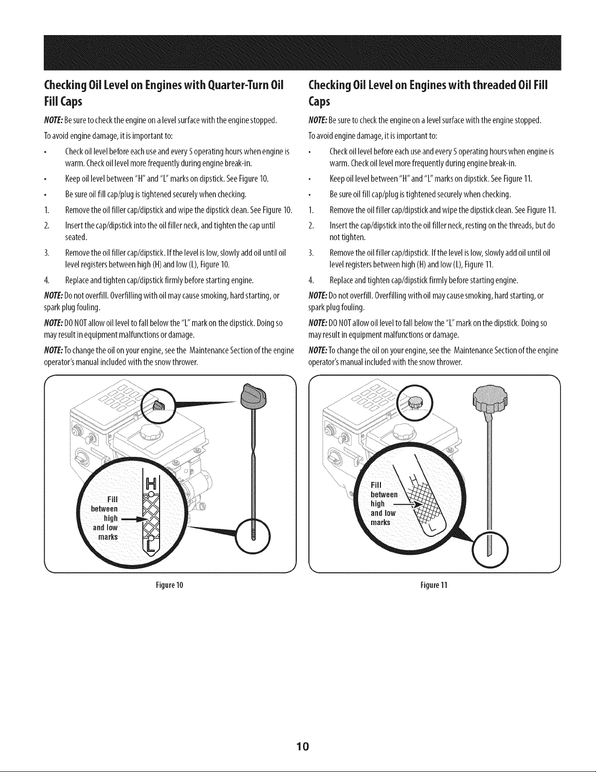
Keepoil levelbetween"H" and"L" markson dipstick.SeeFigure10.
Besureoil fill cap/plugistightenedsecurelywhenchecking.
1. Removethe oil filler cap/dipstkkandwipethedipstickclean.SeeFigure10.
2. Insertthe cap/dipstkkinto the oil filler neck,andtighten the capuntil
seated.
3. Removethe oil filler cap/dipstkk.Ifthe levelis low,slowlyaddoil until oil
levelregistersbetweenhigh(H)andlow (L),Figure10.
4. Replaceandtightencap/dipstkkfirmly beforestartingengine.
NOTE:Donotoverfill.Overfillingwith oil maycausesmoking,hardstarting,or
sparkplugfouling.
NOTE:DONOTallowoillevelto fall belowthe"L" markonthedipstick.Doingso
mayresultinequipmentmalfunctionsor damage.
NOTE:Tochangetheoilon yourengine,seethe MaintenanceSectionofthe engine
operator'smanualincludedwith the snowthrower.
Figure10
CheckingOil Levelon Engineswith threaded Oil Fill
Caps
NOTE:Besureto checktheengineona levelsurfacewith theenginestopped.
Toavoidenginedamage,it isimportantto:
Checkoil levelbeforeeachuseandevery5 operatinghourswhenengineis
warm.Checkoillevelmorefrequentlyduringenginebreak-in.
Keepoil levelbetween"H"and"L" marksondipstick.SeeFigure11.
Besureoil fill cap/plugistightenedsecurelywhenchecking.
1. Removethe oil filler cap/dipstkkandwipethedipstickclean.SeeFigure11.
2. Insertthe cap/dipstkkintothe oil filler neck,restingonthe threads,butdo
nottighten.
3. Removethe oil filler cap/dipstick.If the levelislow,slowlyaddoil until oil
levelregistersbetweenhigh (H)andlow (L),Figure11.
4. Replaceandtighten cap/dipstickfirmly beforestartingengine.
NOTE:Donotoverfill.Overfillingwithoil maycausesmoking,hardstarting,or
sparkplugfouling.
NOTE:DONOTallowoil levelto fallbelowthe"L"markonthedipstick.Doingso
mayresultinequipmentmalfunctionsor damage.
NOTE:Tochangetheoilonyourengine,seethe MaintenanceSectionof the engine
operator'smanualincludedwith the snowthrower.
Figure11
10
Adjustments Auger and Drive Control Cables
SkidShoes
Itis not recommendedthat youoperatethissnowthroweron gravelasit can
easilypickupandthrowloosegravel,causingpersonalinjury ordamageto the
snowthrowerandsurroundingproperty.
Thesnowthrowerskidshoesareadjustedupwardat thefactoryfor shipping
purposes.Adjustthemdownwardpriorto operatingthe machine.
Forclosesnowremovalon asmoothsurface,adjusttheskidshoessothattheshave
plateon thebottomof the augerhousingisjust offthe ground.
Adjusttheskidshoesto alowerpositionto raisetheshaveplateoffthe ground
whenclearingunevenareas,suchasa ribbontypedrivewayor agraveldriveway
NOTE:Ifyouchooseto operatethesnowthroweron agravelsurface,keepthe skid
shoesin positionfor maximumclearancebetweenthegroundandtheshaveplate.
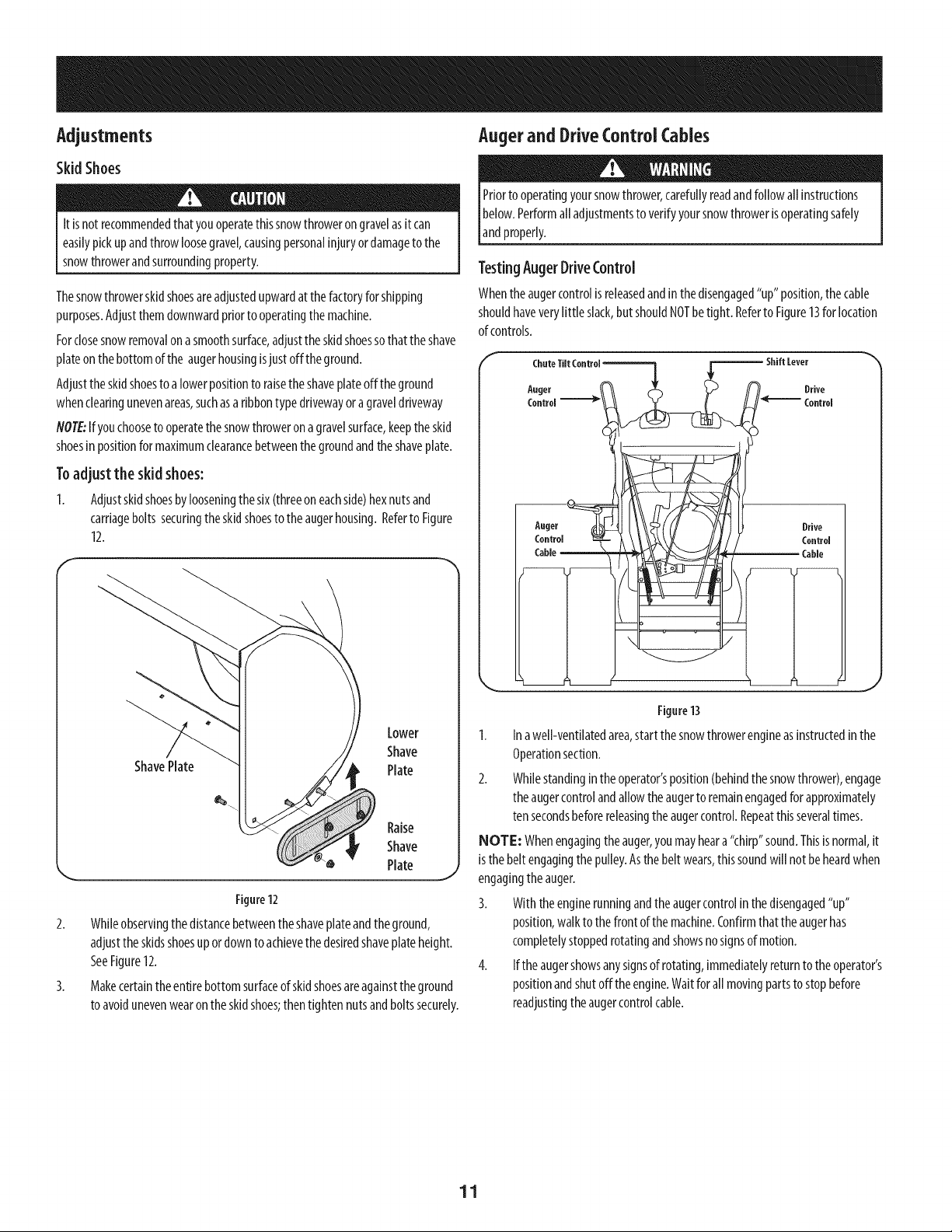
Toadjust the skid shoes:
1. Adjustskidshoesbylooseningthesix(threeoneachside)hexnutsand
carriageboltssecuringtheskidshoestotheaugerhousing.RefertoFigure
12.
ShavePlate
Lower
Shave
Plate
Raise
Shave
. Plate j
Figure12
2. Whileobservingthe distancebetweentheshaveplateandtheground,
adjustthe skidsshoesup ordownto achievethe desiredshaveplateheight.
SeeFigure12.
3. Makecertainthe entirebottomsurfaceof skidshoesareagainsttheground
to avoidunevenwearontheskidshoes;thentightennutsandboltssecurely.
Priorto operatingyoursnowthrower,carefullyreadandfollowall instructions
below.Performalladjustmentsto verifyyoursnowthrowerisoperatingsafely
andproperly.
TestingAugerDriveControl
Whentheaugercontrolis releasedandinthedisengaged"up" position,the cable
shouldhaveverylittle slack,but shouldNOTbetight. Referto Figure13for location
of controls.
F
ChuteTiltControl_ _ Shift Lever
2_
Auge, n. ,, ve
H- ---coot,u,
Auger d___ Drive
J
Figure13
1. Inawell-ventilatedarea,startthesnowthrowerengineasinstructedinthe
Operationsection.
2. Whilestandingin theoperator'sposition(behindthesnowthrower),engage
theaugercontrolandallowthe augerto remainengagedfor approximately
tensecondsbeforereleasingtheaugercontrol.Repeatthisseveraltimes.
NOTE: Whenengagingtheauger,you mayheara"chirp"sound.Thisis normal,it
is the beltengagingthe pulley.Asthebelt wears,thissoundwill not beheardwhen
engagingthe auger.
3. Withtheenginerunningandtheaugercontrolin thedisengaged"up"
position,walkto thefrontof the machine.Confirmthatthe augerhas
completelystoppedrotatingandshowsnosignsof motion.
4. Ifthe augershowsanysignsof rotating,immediatelyreturntothe operator's
positionandshutoff the engine.Waitfor all movingpartsto stopbefore
readjustingtheaugercontrolcable.
11
TestingWhee{ Dr}reContro{& SpeedSelectorLever
RefertoFigure13for{ocationofcontro{s.
I. Movethespeedselectorshift{everintosixth(6)posit{on.
2. Withthewheeldrivecontro{released,pushthesnowthrowerforward,thenpull
it back.Themachineshouldmovefreely.
3. Engagethedrivecontrolandattempttomovethemachinebothforwardand
back,resistanceshouldbefelt.
4. Movethespeedselectorshiftleverintothefastreverse(R2)positionandrepeat
theprevioustwosteps.
Ifyouexperiencedresistancerollingtheunit,eitherwhenrepos{tioningthespeed
selectorshiftleverfrom6 toR2orwhenattemptingto movethemachinewiththedrive
controlreleased,adjustthedrivecontrolimmediately.SeeAdjustingDriveandAuger
Controls.
AdjustingWhee{Dr}re& Auger(ontro{s
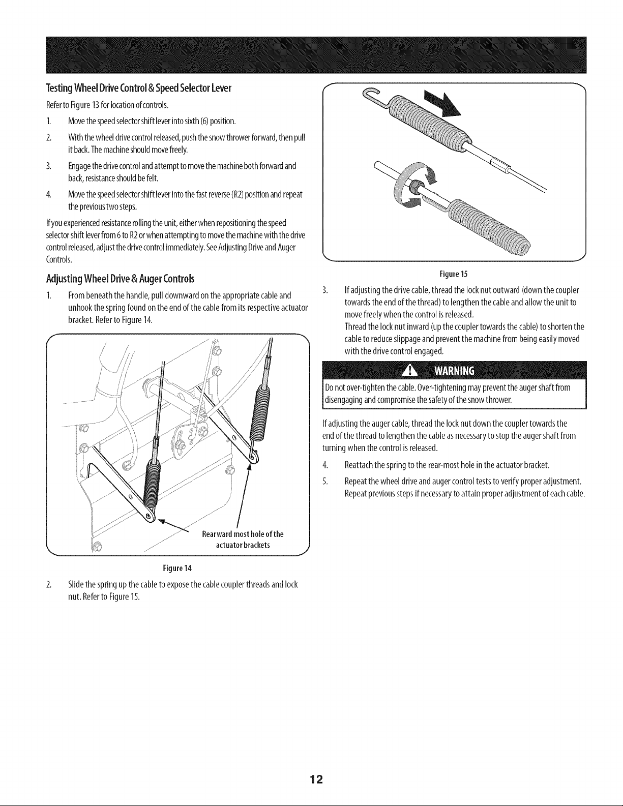
1. Frombeneaththehandle,pulldownwardontheappropriatecableand
unhookthespringfoundontheendofthecablefromitsrespectiveactuator
bracket.Referto Figure14.
Rearwardmostholeofthe
...... actuatorbrackets
Figure14
2. S{{dethespringup the cab{eto exposethe cab{ecoup{erthreadsand{ock
nut.Referto Figure15.
J
Figure15
Ifadjustingthedrivecable,threadthelocknut outward(downthe coupler
towardsthe endof the thread)to lengthenthe cableandallowthe un{tto
movefreelywhenthecontrol{sreleased.
Threadthelocknut inward(upthecouplertowardsthe cable)to shortenthe
cableto reduceslippageandpreventthemach{nefrom beingeas{lymoved
w{ththedr{vecontrolengaged.
Donotover-tightenthecable.Over-tighteningmaypreventtheaugershaftfrom
disengagingandcompromisethesafetyof thesnowthrower.
Ifadjustingtheaugercable,threadthelocknut downthecouplertowardsthe
endofthe threadto lengthenthecableasnecessaryto stoptheaugershaftfrom
turningwhenthecontrolisreleased.
4. Reattachthespringto the rear-mostholeintheactuatorbracket.
5. Repeatthewheeldriveandaugercontrolteststo verifyproperadjustment.
Repeatpreviousstepsif necessaryto attainproperadjustmentofeachcable.
12
f SpeedSelector "
Drive Chute ControF M
Headlight
DriftCutters
Clean-outTool
\
Augers
ChuteAssembly
.%o,
Skid Shoes
AugerControl
Wheel SteeringControl
Chute
Control
Oil Filler
Cap/Dipstick
PrimerKey
Ch°kTh
Oil Drain
Figure
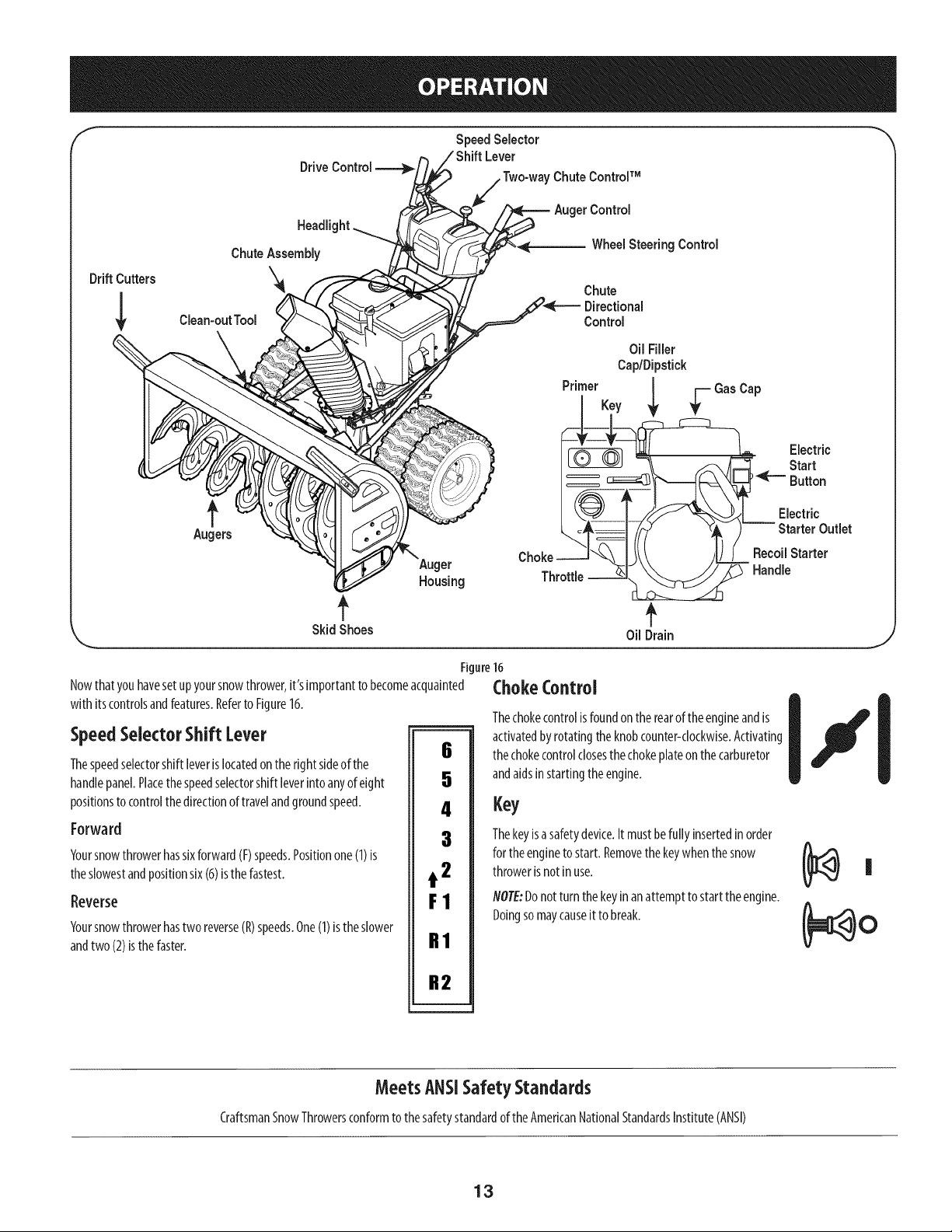
Nowthatyouhavesetupyoursnowthrower,it'simportanttobecomeacquainted
with itscontrolsandfeatures.Referto Figure16.
SpeedSelector Shift Lever
Thespeedselectorshift leverislocatedontheright sideof the
handlepanel.Placethespeedselectorshift leverintoanyof eight
positionsto controlthe directionof travelandgroundspeed.
Forward
Yoursnowthrowerhassixforward(F)speeds.Positionone(1)is
theslowestandpositionsix(6)isthefastest.
Reverse
Yoursnowthrowerhastwo reverse(R)speeds.One(1)istheslower
andtwo (2)isthefaster.
6
5
4
3
t 2
F1
R1
R2
16
ChokeControl
Thechokecontrolisfoundontherearof theengineandis
activatedbyrotatingthe knobcounter-clockwise.Activating
thechokecontrolclosesthe chokeplateon thecarburetor
andaidsinstartingtheengine.
Key
Thekeyisasafetydevice.It mustbefully insertedinorder
for theengineto start. Removethekeywhenthesnow
throwerisnotin use.
NOTE:Donotturn thekeyinanattempt to startthe engine.
Doingsomaycauseit to break.
Electric
Start
Button
Electric
Outlet
Recoil Starter
Handle
MeetsANSISafety Standards
CraftsmanSnowThrowersconformtothesafetystandardof theAmericanNationalStandardsInstitute(ANSI)
13
ThrottleControl
==-,.-
GasCap
Unthreadthe gascapto addgasolineto thefueltank.
OUDrain
Engineoil canbedrainedthroughtheoil drain.
Thethrottlecontrolislocatedon therearoftheengine.Itregulatesthe speedof the
engineandwill shutoffthe enginewhenmovedinto theSTOPposition.
Primer
Depressingtheprimerforcesfueldirectlyintotheengine'scarburetorto aidin
cold-weatherstarting.
0U Fili [ _,,_.J__,.
Engineoil levelcanbe checkedandoil addedthroughthe
oil fill.
RecoilStarter Handle
Thishandleisusedto manuallystartthe engine.
ElectricStarterButton
Pressingtheelectricstarterbuttonengagestheengine'selectricstarterwhen
pluggedinto a 120Vpowersource.
ElectricStarterOutlet
Requirestheuseof athree-prongoutdoorextensioncordanda 120Vpowersource/
walloutlet.
Augers
Whenengaged,the augersrotateanddrawsnowinto the augerhousing.
ChuteAssembly
Snowdrawninto the augerhousingisdischargedoutthechuteassembly.
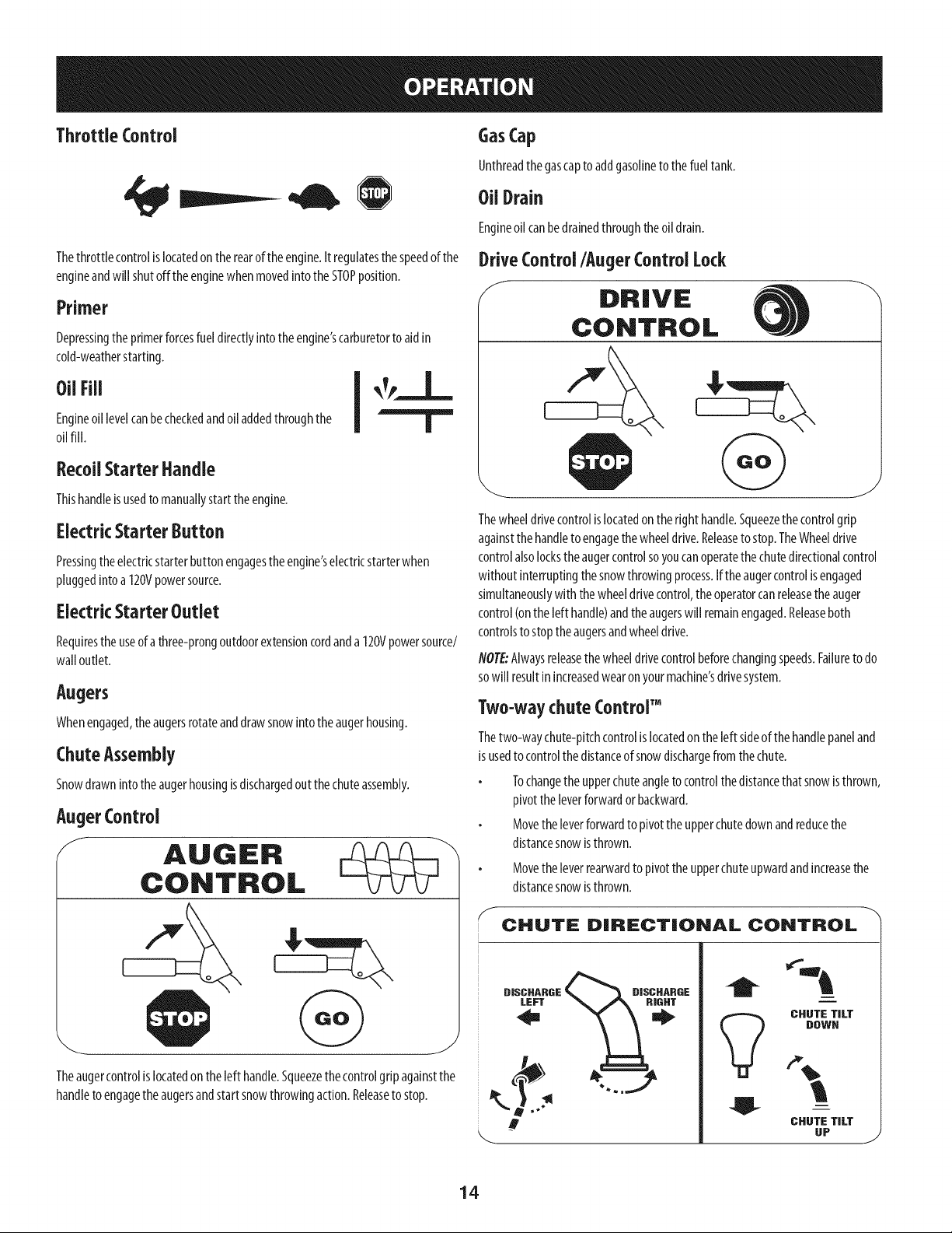
AugerControl
f AUGER
CONTROL
J
Theaugercontrolislocatedon theleft handle.Squeezethecontrolgripagainstthe
handleto engagetheaugersandstartsnowthrowingaction.Releaseto stop.
DriveControl/Auger Control Lock
/ DRIVE
CONTROL
J
Thewheeldrivecontrolislocatedon the righthandle.Squeezethecontrolgrip
againstthe handleto engagethe wheeldrive.Releaseto stop.TheWheeldrive
controlalsolocksthe augercontrolsoyoucanoperatethe chutedirectionalcontrol
without interruptingthe snowthrowingprocess.If the augercontrolisengaged
simultaneouslywith the wheeldrivecontrol,theoperatorcanreleasethe auger
control(onthe left handle)andthe augerswill remainengaged.Releaseboth
controlsto stoptheaugersandwheeldrive.
NOTE:Alwaysreleasethewheeldrivecontrolbeforechangingspeeds.Failureto do
sowill resultinincreasedwearonyourmachine'sdrivesystem.
Two-waychute Control"
Thetwo-waychute-pitchcontrolislocatedon the left sideof the handlepaneland
is usedto controlthedistanceofsnowdischargefromthechute.
Tochangetheupperchuteangletocontrolthe distancethat snowisthrown,
pivottheleverforwardor backward.
Movetheleverforwardto pivottheupperchutedownandreducethe
distancesnowisthrown.
Movetheleverrearwardto pivot theupperchuteupwardandincreasethe
distancesnowisthrown.
S
CHUTE DIRECTIONAL CONTROL
DISCHARGE
LEFT
1;DISDHARDE
i
CHUTE TILT
DOWN
CHUTE TILT
UP
J
14
NOTE:Toincreaseordecreasethetensiononthetwo-waychutecontrol,tightenor
loosenthewingknobonthechuteassembly.
ChuteDirectional Control
Thechutedirectionalcontrolis locatedonthe left sideofthesnowthrower.
Tochangethedirectioninwhichsnowisthrown,crankclockwiseto
dischargeto theleft andcounterclockwiseto dischargeto theright.
SkidShoes
Positiontheskidshoesbasedonsurfaceconditions.Adjustupwardforhard-packed
snow.Adjustdownwardwhenoperatingongravelorcrushedrocksurfaces.
Wheel Steering Controls
Theleft andrightwheelsteeringcontrolsarelocatedonthe undersideofthe
handles.Squeezetheright controlto turn right;squeezetheleft controlto turn left.
NOTE:Operatethe snowthrowerin openareasuntil youarefamiliarwith these
controls.
Headlight
Theheadlightis locatedinsideofthe handlepanel.
Drift cutters
Thedrift cuttersaredesignedforusein deepsnow.Theiruseisoptionalfor normal
snowconditions.Maneuverthe snowthrowersothatthecutterspenetratea high
standingsnowdrift to assistsnowfalling into theaugersforthrowing.
Clean-OutTool
Thechuteclean-outtool isconvenientlyfastenedto therearoftheaugerhousing
with amountingclip.Shouldsnowandicebecomelodgedin thechuteassembly
duringoperation,proceedasfollowsto safelycleanthe chuteassemblyandchute
opening:
Neveruseyour handsto cleara cloggedchuteassembly.Shutoffengine
and remain behindhandlesuntil all moving partshavestoppedbefore
unclogging.
1. ReleaseboththeAugerControlandtheWheeldrivecontrol.
2. Stoptheenginebyremovingthekey.
3. Removethe clean-outtoolfrom the clipwhichsecuresit to the rearof the
augerhousing.
4. Usetheshovel-shapedendofthe clean-outtoolto dislodgeandscoopany
snowandicewhichhasformedinandnearthechuteassembly.
5. Refastentheclean-outtooltothe mountingclipon therearof theauger
housing,reinsertthekeyandstartthesnowthrower'sengine.
6. Whilestandinginthe operator'sposition(behindthesnowthrower),engage
theaugercontrolfor afewsecondsto clearanyremainingsnowandicefrom
thechuteassembly.
BeforeStarting Engine
Read,understand,andfollow all instructionsandwarningsonthe machine
and inthis manualbeforeoperating.
Oil
Theunit wasshippedwith oilin theengine.Checkoil levelbeforeeachoperation
to ensureadequateoil intheengine.Forfurther instructions,referto the Service&
Maintenancesectionof thismanual.
NOTE:Besureto checktheengineona levelsurfacewith theenginestopped.
1. Removethe oil filler cap/dipstickandwipethe dipstickclean.
2. Insertthe cap/dipstickintothe oil filler neck,andtightenthecapturning
clockwiseuntil capisseated.
flOTE:Onsomeengines,athreadedscrewcapwill bepresentinsteadof
thequarterturn lockingcap.In theinstanceof athreadedoil cap/dipstick,
DONOTscrewthecap/dipstickin to check.Checkthe oil byrestingthe cap/
dipstickonthethreads,but notscrewingit in.
Removethe oil filler cap/dipstick.If the levelislow,slowlyaddoil(5W-30,
with a minimumclassificationof SF/SG)until oil levelregistersbetweenhigh
(H)andlow (L).
flOTE:Donot overfill.Overfillingwithoil mayresultinenginesmoking,hard
startingorsparkplugfouling.
Replaceandtightencap/dipstickfirmly beforestartingengine
Gasoline
Useextremecarewhen handlinggasoline.Gasolineisextremely flammable
andthe vaporsare explosive.Neverfuel the machineindoorsor while the
engineishot or running. Extinguishcigarettes,cigars,pipesandother
sourcesof ignition.
Useautomotivegasoline(unleadedorlowleadedto minimizecombustionchamber
deposits)with aminimumof 87octane.Gasolinewith upto 10%ethanolor 15%
MTBE(MethylTertiaryButylEther)canbeused.Neveruseanoil/gasolinemixture
ordirty gasoline.Avoidgetting dirt,dust,orwaterinthefueltank.DONOTuseE85
gasoline.
Refuelinawell-ventilatedareawith theenginestopped.Donotsmokeor
allowflamesor sparksintheareawheretheengineis refueledorwhere
gasolineisstored.
Donotoverfillthefueltank.Afterrefueling,makesurethetankcapisclosed
properlyandsecurely.
Becarefulnot to spillfuel whenrefueling.Spilledfuelor fuel vapormay
ignite.If anyfuelisspilled,makesuretheareaisdrybeforestartingthe
engine.
Avoidrepeatedorprolongedcontactwith skinor breathingofvapor
1. Cleanaroundfuelfill beforeremovingcapto fuel to preventdebrisfrom
enteringfuel tank..
2. Afuellevelindicatoris locatedinthe fuel tank.Filltank until fuelreachesthe
fuel levelindictor.SeeFigure10inset.Becarefulnot to overfill.
15
Starting The Engine
Alwayskeephandsandfeet dear of moving parts. Donot usea pressurized
starting fluid. Vaporsareflammable.
NOTE:Allowtheengineto warmup forafew minutesafterstarting.The
enginewill notdevelopfull poweruntil it reachesoperatingtemperatures.
Makecertainboththeaugercontrolandwheeldrivecontrolarein the
disengaged(released)position.
Insertkeyintoslot.Makesureit snapsinto place.Donotattemptto turn the
key.
NOTE:Theenginecannotstartwithout thekeyfullyinsertedinto the
ignitionswitch.
Eiectrk Starter
Theoptional e[ectrk starter isequipped with agrounded powerplug, and
isdesignedto operateonan extensioncord ratedfor 15ampsat 125volts,
groundedandratedfor outdooruseusing120volt AChouseholdcurrent,it
mustbe usedwith a properly groundedthree-prong receptacleat ai[ times
to avoidthe possibility of eiectrk shock.Followall instructionscarefully
prior to operating theelectricstarter.
Determinethatyourhome'swiring isathree-wiregroundedsystem.Askalicensed
electricianif youarenot certain.
If youhaveagroundedthree-prongreceptacle,proceedasfollows:
1. Plugan extensioncordintotheoutlet locatedontheengine'ssurface.Plug
theotherendof extensioncordinto athree-prong120-volt,grounded,AC
outletina well-ventilatedarea.
6. Astheenginewarms,slowlyrotatethe chokecontrolto the RUNposition.If
theenginefalters,restartengineandrunwith chokeat half-chokeposition
for ashortperiodof time,andthenslowlyrotatethechokeinto the RUN
position.
7. Afterengineisrunning,disconnectpowercordfrom electricstarter.When
disconnecting,alwaysunplugthe endat thewalloutlet beforeunplugging
theoppositeendfromtheengine.
RecoilStarter
Donot pull the starter handlewhilethe engine running.
1. Movethrottlecontrolto FAST(rabbit)_1 position.
2. Movechoketo the CHOKEI,,1¢1position(coldenginestart).Ifengineis
warm,placechokeintheRUNposition.
3. Pushprimerthreetimes,makingsureto coverventholewhenpushing.
Ifengineiswarm,pushprimeronlyonce.Alwayscoverventholewhen
pushing.Coolweathermayrequireprimingto berepeated.
4. Pullgentlyonthestarterhandleuntil it beginsto resist,thenpullquicklyand
forcefullyto overcomethecompression.Engineshouldstart.Donot releasethe
handleandallowitto snapback.ReturnropeSLOWLYto originalposition.If
required,repeatthisstep.
5. Astheenginewarms,slowlyrotatethe chokecontrolto the RUNposition.If
theenginefalters,restartengineandrunwith chokeat half-chokeposition
for ashortperiodof time,andthenslowlyrotatethechokeinto the RUN
position.
Toavoid unsupervisedengine operation, neverleavethe machine
unattendedwith the engine running.Turnthe engineoff after useand
removekey.
Theextensioncordcanbe any length, but must be ratedfor 15ampsat 125
volts, groundedand ratedfor outdoor use.
2. Movethrottle controlto FAST(rabbit)_ position.
3. Movechoketo theCHOKEposition [,jC[ (coldenginestart).
NOTE:Iftheengineisalreadywarm,placechokecontrolintheRUNposition
insteadof CHOKE12¢I
position.
4. Pushprimerthreetimes(3x),makingsureto coverventholein primerbulb
whenpushing.Ifengineiswarm,pushprimeronlyonce.Alwayscovervent
holewhenpushing.Coolweathermayrequireprimingto berepeated.
5. Pushstarterbuttontostart engine.Oncetheenginestarts,immediately
releasestarterbutton.Electricstarterisequippedwith thermaloverload
protection;systemwill temporarilyshut-downtoallow starterto coolif
electricstarterbecomesoverloaded.
Stopping The Engine
Afteryouhavefinishedsnow-throwing,runengineforafew minutesbefore
stoppingto helpdryoff anymoistureontheengine.
1. Movethrottlecontrolto STOP(_ position.
ine. Backfireor en occur.
2. Removethekey.Removingthekeywillreducethepossibilityof unauthorized
startingoftheenginewhileequipmentisnotinuse.Keepthekeyinasafeplace.
Theenginecannotstartwithoutthekey.
3. Wipeall snowandmoisturefromtheareaaroundtheengineaswellasthe
areainandaroundthe wheeldrivecontrolandaugercontrol.Also,engage
andreleasebothcontrolsseveraltimes.
Toprolong starter life, useshort starting cycles(5secondsmaximum,then
wait one minute).
16
ToEngageWheel Drive
1. Withthethrottle controlintheFast(rabbit)_j_ position,movespeed
selectorleverinto oneof thesixforward(F)positionsortwo reverse(R)
positions.Selectaspeedappropriateforthesnowconditionsanda pace
you'recomfortablewith.
flOTE:Whenselectinga DriveSpeed,usethe slowerspeedsuntil youare
comfortableandfamiliarwith the operationofthesnowthrower.
2. Squeezethedrivecontrolagainstthe handleandthe snowthrowerwill
move.Releaseit anddrivemotionwi[[stop.
NOTE:NEVERrepositionthe speedselectorlever(changespeedsor direction
oftravel)without first releasingthedrivecontrolandbringingthe snow
throwerto acompletestop.Doingsowi[[resultin prematurewearto the
snowthrower'sdrivesystem.
ToEngageAuger
1. Toengagetheaugerandstart throwingsnow,squeezetheaugercontrol
againsttheleft handle.Releaseto stoptheaugers.
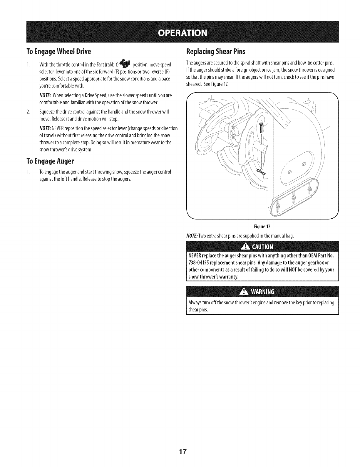
ReplacingShearPins
Theaugersaresecuredtothe spiralshaftwith shearpinsandbow-tiecotterpins.
Iftheaugershouldstrikeaforeignobjector kejam, the snowthrowerisdesigned
sothatthe pinsmayshear.Iftheaugerswill notturn,checkto seeif thepinshave
sheared.SeeFigure17.
Figure17
NOTE:Twoextrashearpinsaresuppliedin themanualbag.
NEVERreplacethe augershearpinswith anything other than OEMPart No.
738-04155replacementshearpins. Anydamageto the augergearboxor
other componentsasa result of failing to dosowill NOTbe coveredbyyour
snowthrower'swarranty.
Alwaysturnoffthesnowthrower'sengineandremovethekeypriortoreplacing
shearpins.
17
MAINTENANCESCHEDULE
Beforeperforminganytypeofmaintenance/service,disengageallcontrolsandstop
theengine.Waituntilallmovingpartshavecometoacompletestop.Removethekey
topreventunintendedstarting.Alwayswearsafetyglassesduringoperationorwhile
performinganyadjustmentsor repairs.
Followthe maintenanceschedulegiven below.Thischart describesservice
guidelinesonly. Usethe ServiceLogcolumnto keeptrackofcompleted
maintenancetasks.TolocatethenearestSearsServiceCenteror to schedule
service,simplycontactSearsat 1-800-4-MY-HOME®.
EachUse
1st5- 8 hours
25 hours
50hours
Annuallyor 100hours
BeforeStorage 1. Fuelsystem 1.
1.
2.
3.
1.
1.
2.
1.
1.
Engineoil level
Looseormissinghardware
Unitandengine.
Engineoil
Engineoilf
Controllinkagesandpivots
Engineoil
Sparkplug
f Underheavyloadorinhigh temperatures
ENGINEMAINTENANCE
1.
2.
3.
1.
1.
2.
1.
1.
Checking Engine Oil
Beforelubricating,repairing,or inspecting,disengageall controlsandstop
engine.Waituntil all movingpartshavecometo a completestop.Removethe
[keyto preventun ntendedf r ngof theeng he.
NOTE: Check the oil level before each use to be sure correct oil level
is maintained.
Check
Tightenorreplace
Clean
Change
Change
Lubewith light oil
Change
Cleanandre-gap,orelsereplacewith
new plug.
Runengineuntil it stopsfrom lackof fuel
oradda gasolineadditiveto thegasin
thetank.
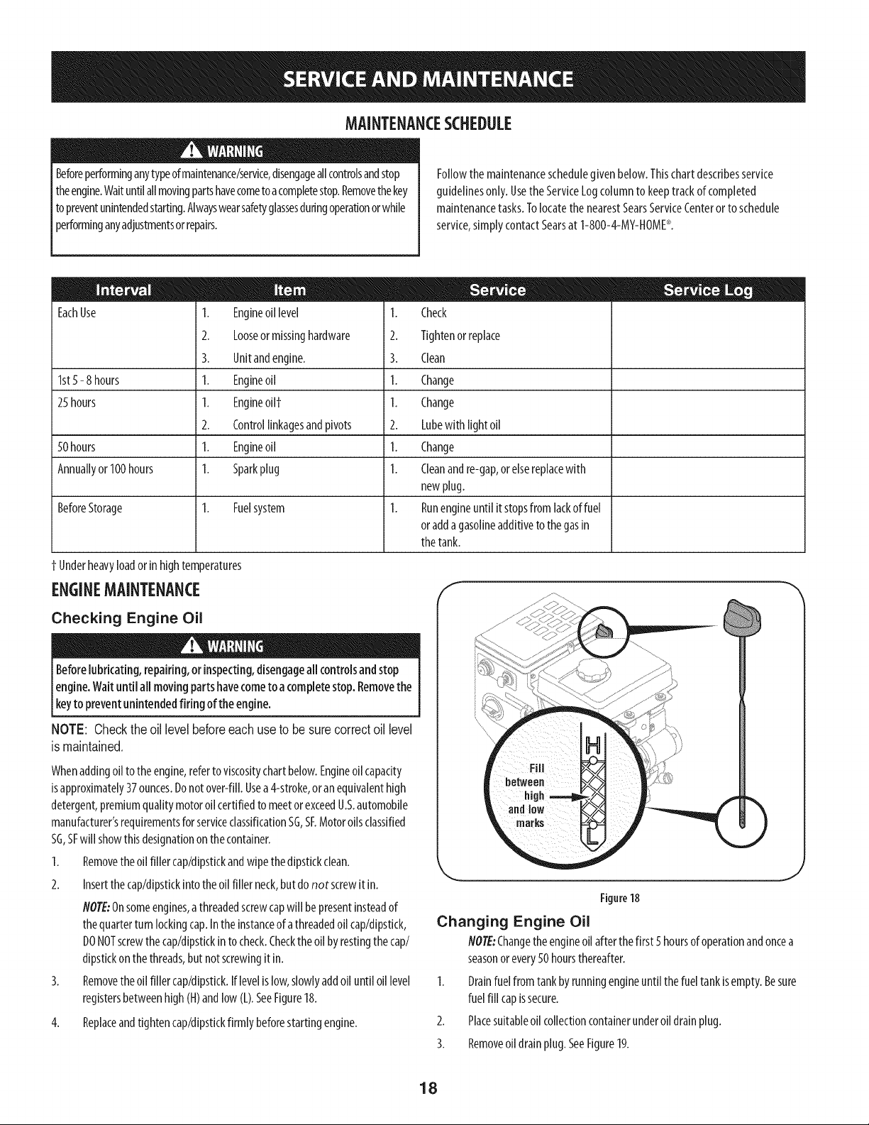
Changing Engine Oil
Figure18
Whenaddingoil to theengine,referto viscositychartbelow.Engineoil capacity
isapproximately37ounces.Donotover-fill.Usea4-stroke,oranequivalenthigh
detergent,premiumqualitymotoroilcertifiedto meetorexceedU.S.automobile
manufacturer'srequirementsforserviceclassificationSG,SF.Motoroilsclassified
SG,SFwill showthisdesignationon thecontainer.
1. Removethe oil filler cap/dipstickandwipethe dipstickclean.
2. Insertthe cap/dipstickinto the oil filler neck,but do not screwit in.
NOTE:Onsomeengines,athreadedscrewcapwill bepresentinsteadof
thequarterturn lockingcap.Inthe instanceof athreadedoil cap/dipstick,
DONOTscrewthe cap/dipstickinto check.Checktheoilby restingthe cap/
dipstickon the threads,butnotscrewingit in.
Removethe oil filler cap/dipstick.Iflevelislow,slowlyaddoil until oil level
registersbetweenhigh(H)andlow(L).SeeFigure18.
4. Replaceandtightencap/dipstickfirmlybeforestartingengine.
J
NOTE:Changethe engineoil afterthefirst 5hoursof operationandoncea
seasonorevery50 hoursthereafter.
1. Drainfuelfrom tankbyrunningengineuntil thefuel tankisempty.Besure
fuel fill capissecure.
2. Placesuitableoil collectioncontainerunderoil drainplug.
3. Removeoil drainplug.SeeFigure19.
18
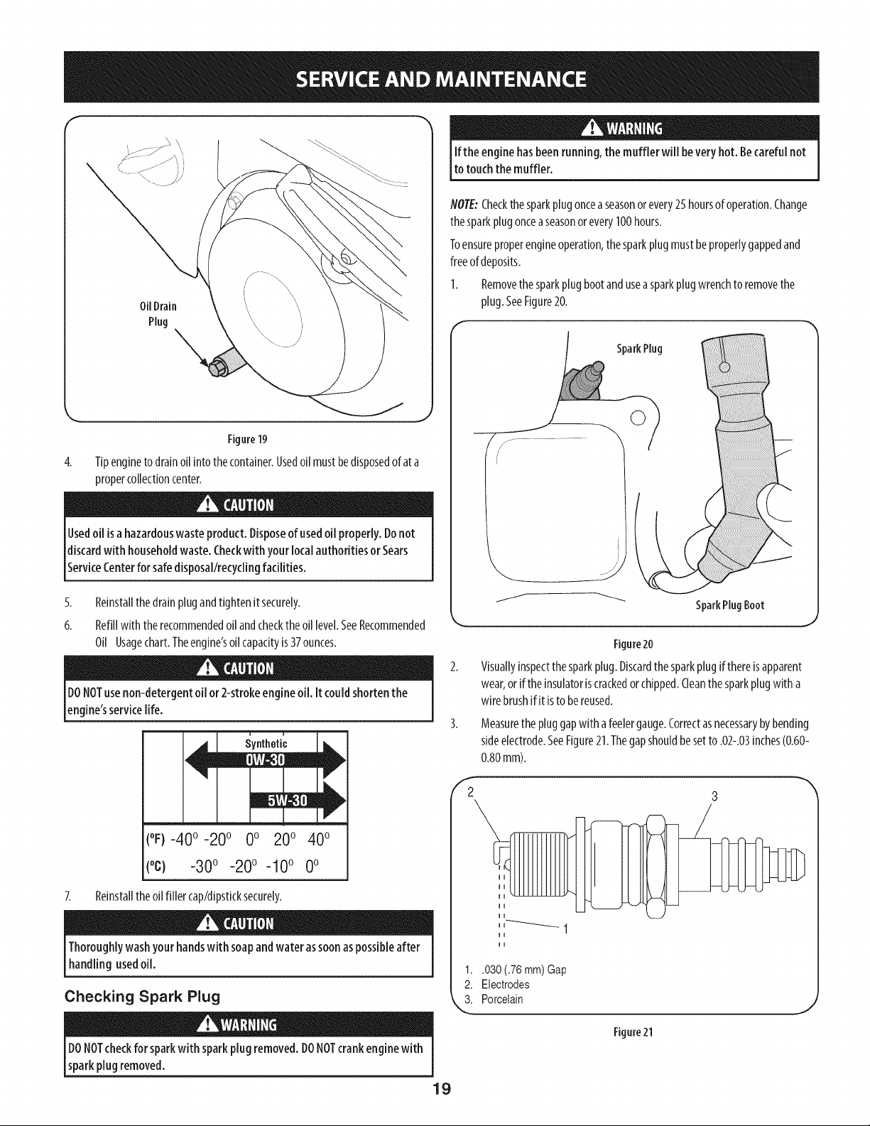
f
Oil Drain
Plug
Figure19
4. Tipengineto drainoil intothecontainer.Usedoil mustbedisposedofat a
propercollectioncenter.
Usedoil isahazardouswaste product. Disposeof usedoil properly.Donot
discardwith householdwaste.Checkwith your localauthorities or Sears
ServiceCenterfor safedisposal/recyclingfacilities.
5. Reinstallthedrainplugandtightenit securely.
6. Refillwith the recommendedoilandchecktheoil level.SeeRecommended
Oil Usagechart.Theengine'soilcapacityis37ounces.
DONOTusenon-detergent oil or 2-strokeengine oil. It could shortenthe
engine'sservicelife.
y.t,oti'o
(%-400 -200 0o 200 400
(°c) -300 -200 -100 0o
7. Reinstalltheoilfiller cap/dipsticksecurely.
Thoroughlywashyour handswith soapandwater assoonaspossibleafter
handling usedoil.
Checking Spark Plug
DONOTcheckfor sparkwith sparkplugremoved.DONOTcrankengine with
sparkplug removed.
Ifthe engine hasbeenrunning,the muffler will be veryhot. Becarefulnot
to touchthe muffler.
NOTE:Checkthesparkplugonceaseasonorevery25hoursof operation.Change
thesparkplugonceaseasonor every100hours.
Toensureproperengineoperation,the sparkplugmustbeproperlygappedand
freeof deposits.
1. Removethe sparkplugbootanduseasparkplugwrenchto removethe
plug.SeeFigure20.
SparkPlug
SparkPlug Boot
F
2
Figure20
Visuallyinspectthesparkplug.Discardthesparkplugifthereis apparent
wear,orif theinsulatoris crackedorchipped.Cleanthesparkplugwith a
wire brushif it isto bereused.
Measurethepluggapwith afeelergauge.Correctasnecessarybybending
sideelectrode.SeeFigure21.Thegapshouldbesetto .02-.03inches(0.60-
0.80mm).
3
1..030 (.76 mm) Gap
2. Electrodes
3. Porcelain
Figure21
J
19
4. Checkthatthe sparkplugwasherisin goodconditionandthreadthe spark
plugin byhandto preventcross-threading.
5. Afterthesparkplug isseated,tightenwith asparkplugwrenchto compress
thewasher.
NOTE:Wheninstallinga newsparkplug,tighten1/2-turnafterthesparkplugseats
to compressthe washer.Whenreinstallingausedsparkplug,tighten1/8-to 1/4-turn
afterthesparkplugseatsto compressthe washer.
' hot andcandama_ me.
Carburetor Adjustment
Thecarburetorisnot useradjustable.ContactSearsParts& Repairforadjustment.
Lubrication
Drive and Shifting Mechanism
Atleastonceaseasonorafterevery25hoursof operation,removerearcover.
Lubricateall chains,sprockets,gears,bearings,shafts,andtheshiftingmechanism.
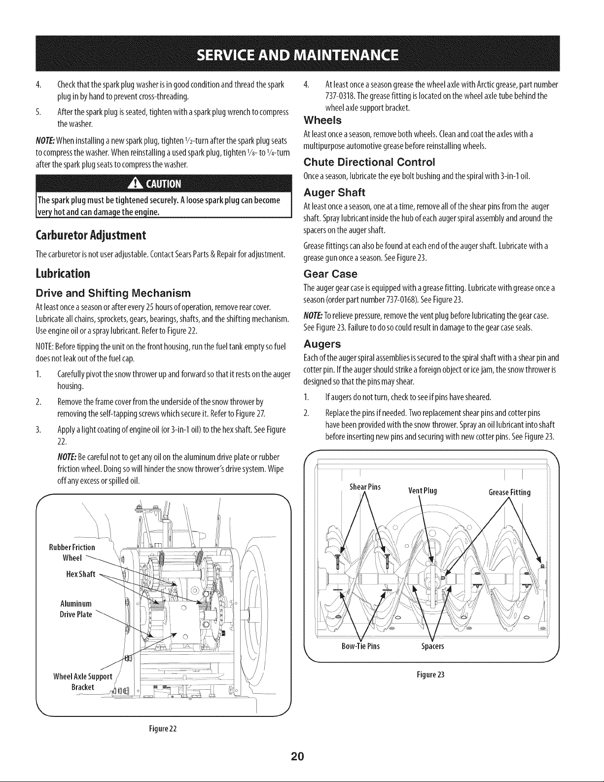
Useengineoil oraspraylubricant.Referto Figure22.
NOTE:Beforetippingthe uniton thefront housing,runthe fuel tankemptysofuel
doesnot leakoutof the fuel cap.
1. Carefullypivotthesnowthrowerupandforwardsothat it restsonthe auger
housing.
2. Removethe framecoverfrom theundersideof the snowthrowerby
removingthe self-tappingscrewswhichsecureit. Referto Figure27.
3. Applya lightcoatingof engineoil (or3-in-1oil) to thehexshaft.SeeFigure
22.
NOTE:Becarefulnotto getanyoil onthe aluminumdriveplateor rubber
frictionwheel.Doingsowill hinderthesnowthrower'sdrivesystem.Wipe
offany excessorspilledoil.
f
Whe=el
4. At leastonceaseasongreasethe wheelaxlewith Arcticgrease,part number
737-0318.Thegreasefitting islocatedonthewheelaxletubebehindthe
wheelaxlesupportbracket.
Wheels
At leastonceaseason,removebothwheels.Cleanandcoattheaxleswith a
multipurposeautomotivegreasebeforereinstallingwheels.
Chute Directional Control
Onceaseason,lubricatethe eyebolt bushingandthe spiralwith 3-in-1oil.
Auger Shaft
At leastonceaseason,oneat atime,removealloftheshearpinsfromthe auger
shaft.Spraylubricantinsidethe hubof eachaugerspiralassemblyandaroundthe
spacersonthe augershaft.
Greasefittings canalsobefoundat eachendoftheaugershaft.Lubricatewith a
greasegunonceaseason.SeeFigure23.
Gear Case
Theaugergearcaseisequippedwith agreasefitting. Lubricatewith greaseoncea
season(orderpartnumber737-0168).SeeFigure23.
NOTE:Torelievepressure,removethevent plugbeforelubricatingthe gearcase.
SeeFigure23. Failureto do socouldresultindamageto thegearcaseseals.
Augers
Eachof theaugerspiralassembliesissecuredto the spiralshaftwith ashearpin and
cotterpin. If theaugershouldstrikeaforeignobjector icejam, thesnowthroweris
designedsothatthepinsmayshear.
1. Ifaugersdonot turn, checkto seeif pinshavesheared.
2. Replacethepinsif needed.Tworeplacementshearpinsandcotterpins
havebeenprovidedwith thesnowthrower.Sprayanoil lubricantintoshaft
beforeinsertingnewpinsandsecuringwith newcotterpins.SeeFigure23.
f
ShearPins Vent Plug GreaseFitting ;;
Bow-fiePins Spacers
Figure23
Figure22
20
Shave Plate and Skid Shoes
Theshaveplateandskidshoeson thebottomofthesnowthroweraresubjectto
wear.Theyshouldbecheckedperiodicallyandreplacedwhennecessary.
Skid Shoes
NOTE:Theskidshoesonthismachinehavetwo wearedges.Whenoneside
wearsout,theycanberotated180°to usetheotheredge.
1. Removethe sixcarriageboltsandhexnutsthatsecurethe two skidshoesto
thesidesoftheaugerhousing.Referto Figure24.
2. Positionthenewskidshoesandsecurewith thecarriageboltsandhexnuts.
Makecertainthe skidshoesareadjustedto belevel.
Shave Plate
1. Removethe hexnutsandcarriageboltsthat securethe shaveplatetothe
bottomofthe housing.Referto Figure24.
2. Removethe rearmosthexnutandcarriagebolt securingthebackof each
skidshoeto the sidesofthe housing.Loosenthefourremaininghexnuts
securingthe skidshoes.
3. Slidetheshaveplateout ofthe off-setslotat the bottomof thehousing,and
from betweentheskidshoesandsidepanelsofthehousing.
4. Withthemountingholestowardthe backof theunit,slidethe newshave
plateinto positionandsecurewiththefastenersremovedpreviously.
J
Figure24
Adjustments
Shift Cable
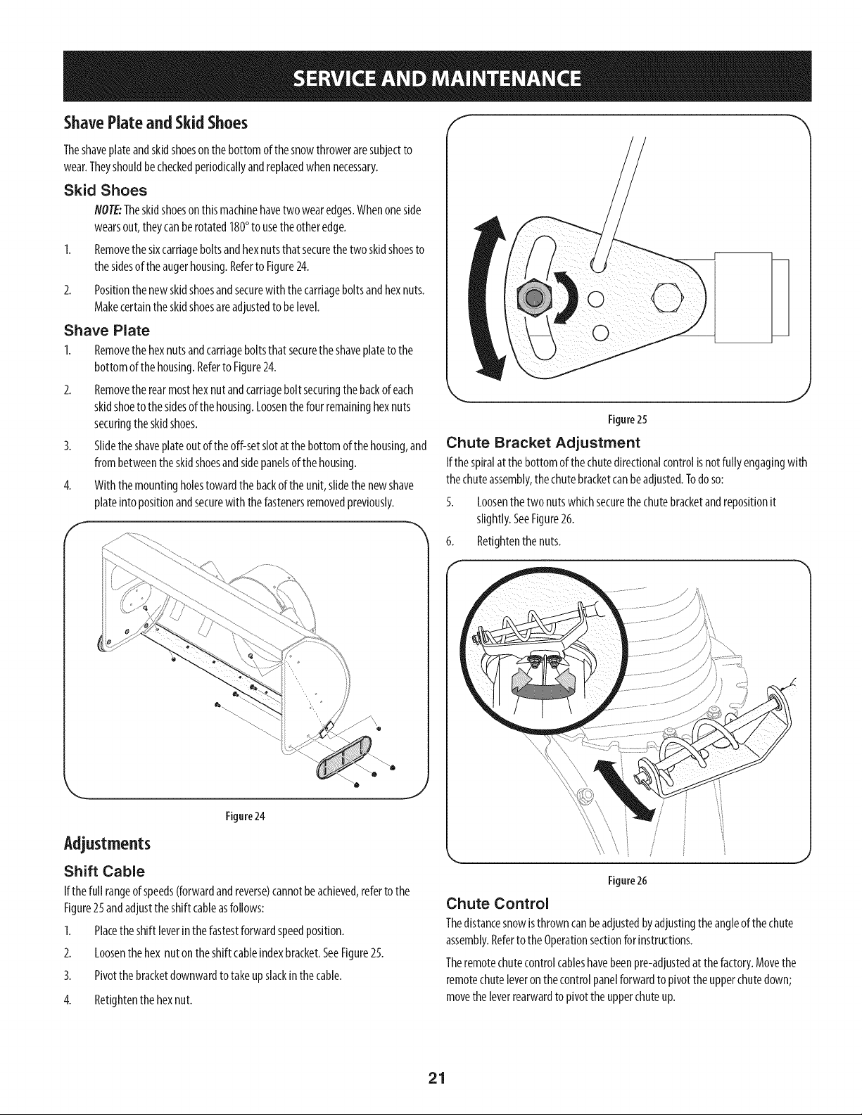
If thefull rangeof speeds(forwardandreverse)cannotbeachieved,referto the
Figure25andadjusttheshift cableasfollows:
1. Placetheshift leverinthe fastestforwardspeedposition.
2. Loosenthehex nutontheshift cableindexbracket.SeeFigure25.
3. Pivotthe bracketdownwardtotakeupslackinthecable.
4. Retightenthehexnut.
J
Figure25
Chute Bracket Adjustment
Ifthespiralatthe bottomof thechutedirectionalcontrolisnotfully engagingwith
thechuteassembly,thechutebracketcanbeadjusted.Todo so:
5. Loosenthetwo nutswhichsecurethechutebracketandrepositionit
slightly.SeeFigure26.
6. Retightenthe nuts.
J
Figure26
Chute Control
Thedistancesnowisthrowncanbeadjustedbyadjustingtheangleof the chute
assembly.Referto theOperationsectionforinstructions.
Theremotechutecontrolcableshavebeenpre-adjustedat thefactory.Movethe
remotechuteleveronthe controlpanelforwardto pivot the upperchutedown;
movetheleverrearwardto pivottheupperchuteup.
21

Wheel drive control
Referto theAdjustmentsectionof the Assemblyinstructionsto adjustthe wheel
drivecontrol.Tofurthercheckthe adjustment,proceedasfollows:
1. Withthesnowthrowertippedforward(becertainto runthe fuel tankdry
beforetipping the unitforward),removethe framecoverunderneaththe
snowthrowerbyremovingtheself-tappingscrews.SeeFigure27.
f
Figure27
2. Locatetheopeningbetweentheaxlesupportbracketandthefront frame
support(SeeFigure28).Lookingthroughthisopening,with thewheeldrive
controlreleased,theremustbeclearancebetweenthefriction wheeland
thedriveplatein all positionsof thespeedselectorlever.
3. Withthewheeldrivecontrolengaged,the frictionwheelmustcontactthe
driveplate.SeeFigure28.
f
Skid Shoes
Referto the Assemblysectionfor instructionsonadjustingtheskidshoes.
Tire Pressure
Referto the Assemblysectionfor instructionsonadjustingthetirepressure.
Belt replacement
Belt Removal Preparation
1. Removethechutecrankrodfrom thechutecrankassemblybyremovingthe
hairpinclip shownin Figure29.Movethechutecrankrodawayfrom the
assemblyasshown.
2. Removethreeself-tapscrewson bothsidesof the transmissionhousingas
showninFigure29.
f
Figure28
4. If thereisnofriction wheelclearance,orthefrictionwheeldoesnotsolidly
contactthedriveplate,re-adjustthe locknut on the lowerendof thedrive
cablefollowingtheinstructionsin theAssemblysection.
5. Reassemblethe framecover.
Auger Control
Referto theAssemblysectionforinstructionson adjustingtheaugercontrolcable.
f
Figure29
Removethe plasticbeltcover,locatedneartheengine,byremovingthe
threeself-tappingscrewsthat secureit. SeeFigure30.
/
/
Figure30
LoosentheboltshowninFigure31securingthebeltkeeperbracketandremove
theotherbolt.Pushthebeltkeeperandbracketupoff theenginepulley.
22
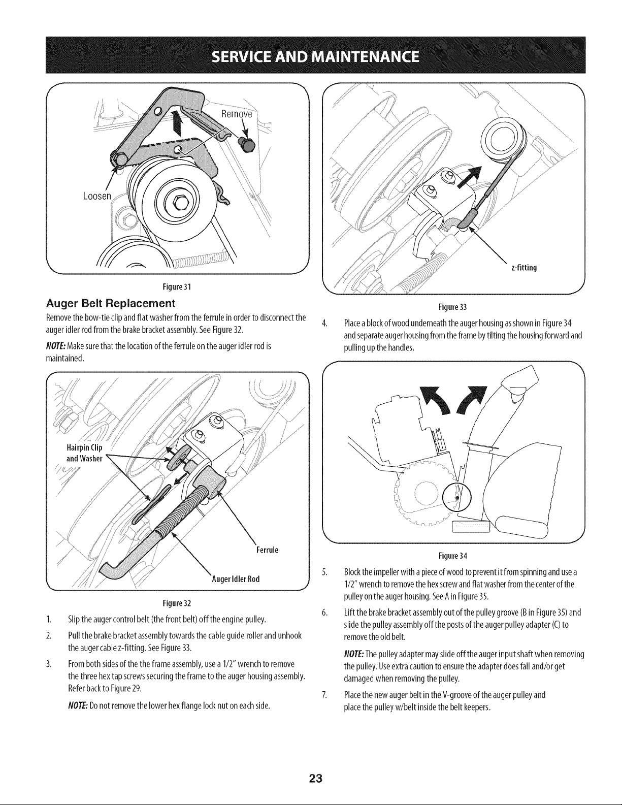
Loosen
Figure31
Auger Belt Replacement
Removethe bow-tieclipandflat washerfrom theferruleinorderto disconnectthe
augeridlerrodfromthebrakebracketassembly.SeeFigure32.
NOTE:Makesurethat thelocationof theferruleontheaugeridlerrodis
maintained.
z-fitting
Figure33
Placea blockofwoodunderneaththeaugerhousingasshownin Figure34
andseparateaugerhousingfromtheframebytiltingthehousingforwardand
pullingupthehandles.
HairpinClip
and Washer
\
Ferrule
Auger Idler Rod
Figure32
1. Sliptheaugercontrolbelt (thefront belt)off the enginepulley.
2. Pullthebrakebracketassemblytowardsthe cableguiderollerandunhook
theaugercablez-fitting. SeeFigure33.
3. Fromboth sidesof the theframeassembly,usea 1/2" wrenchto remove
thethreehextapscrewssecuringtheframeto theaugerhousingassembly.
Referbackto Figure29.
NOTE:Donotremovethelowerhexflangelocknutoneachside.
Figure34
5. Blockthe impellerwithapieceofwoodto preventitfromspinningandusea
1/2"wrenchto removethehexscrewandflat washerfrom thecenterof the
pulleyonthe augerhousing.SeeAinFigure35.
6. Liftthe brakebracketassemblyout of thepulleygroove(BinFigure35)and
slidethepulleyassemblyoffthe postsof theaugerpulleyadapter(C)to
removethe oldbelt.
NOTE:Thepulleyadaptermayslideoff the augerinputshaftwhenremoving
thepulley.Useextracautionto ensurethe adapterdoesfall and/orget
damagedwhenremovingthepulley.
Placethe newaugerbelt in theV-grooveof theaugerpulleyand
placethe pulleyw/belt insidethe beltkeepers.
23
!
/
Brake
pterPost
%
Figure35
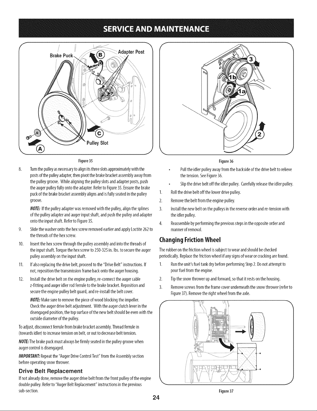
8. Turnthepulleyasnecessarytoalignitsthreeslotsapproximatelywith the
postsof thepulleyadapter,thenpivotthebrakebracketassemblyawayfrom
thepulleygroove.Whilealigningthepulleyslotsandadapterposts,push
theaugerpulleyfullyontotheadapter.Referto Figure35.Ensurethe brake
puckof thebrakebracketassemblyalignsandisfullyseatedinthepulley
groove.
NOTE:If thepulleyadapterwasremovedwith the pulley,alignthesplines
of thepulleyadapterandaugerinputshaft,andpushthe pulleyandadapter
ontothe inputshaft.Referto Figure35.
9. SlidethewasherontothehexscrewremovedearlierandapplyLoctite262to
thethreadsofthehexscrew.
10. Insertthe hexscrewthroughthepulleyassemblyandintothethreadsof
theinputshaft.Torquethe hexscrewto 250-325in.Ibs.to securethe auger
pulleyassemblyontheinputshaft.
11. If alsoreplacingthe drivebelt,proceedto the"DriveBelt"instructions.If
not,repositionthetransmissionframebackontotheaugerhousing.
12. Installthedrivebelton theenginepulley,re-connecttheaugercable
z-fitting andaugeridlerrodferruletothe brakebracket.Repositionand
securethe enginepulleybeltguard,andre-installthe belt cover.
NOTE:Makesureto removethe pieceof woodblockingthe impeller.
Checkthe augerdrivebeltadjustment.With theaugerclutchleverinthe
disengagedposition,thetopsurfaceof thenewbeltshouldbeevenwith the
outsidediameterof thepulley.
Toadjust,disconnectferrulefrombrakebracketassembly.Threadferrulein
(towardsidler)to increasetensionon belt,orout to decreasebelt tension.
NOTE:Thebrakepuckmustalwaysbefirmly seatedinthepulleygroovewhen
augercontrolisdisengaged.
IMPORTANT:Repeatthe "AugerDriveControlTest"from theAssemblysection
beforeoperatingsnowthrower.
Drive Belt Replacement
If notalreadydone,removetheaugerdrivebeltfrom thefrontpulleyof the engine
doublepulley.Referto "AugerBeltReplacement"instructionsintheprevious
sub-section.
\ J
Figure36
Pullthe idlerpulleyawayfrom thebacksideof thedrivebeltto relieve
thetension.SeeFigure36.
Slipthedrivebeltoff theidlerpulley.Carefullyreleasetheidlerpulley.
1. Rollthedrivebeltoffthe lowerdrivepulley.
2. Removethebeltfrom theenginepulley.
3. Installthe newbelt onthepulleysinthereverseorderandre-tensionwith
theidlerpulley.
4. Reassemblebyperformingthepreviousstepsintheoppositeorderand
mannerof removal.
Changing Friction Wheel
Therubberon the frictionwheelissubjectto wearandshouldbechecked
periodically.Replacethefrictionwheelifanysignsof wearorcrackingarefound.
1. Runtheunit'sfueltankdrybeforeperformingStep2. Donot attemptto
pourfuel fromtheengine.
2. Tipthesnowthrowerupandforward,sothat it restson thehousing.
3. Removescrewsfrom theframecoverunderneaththe snowthrower(referto
Figure37).Removetheright wheelfrom theaxle.
....e
24
Figure37
J
4.
f
5.
6.
f
8.
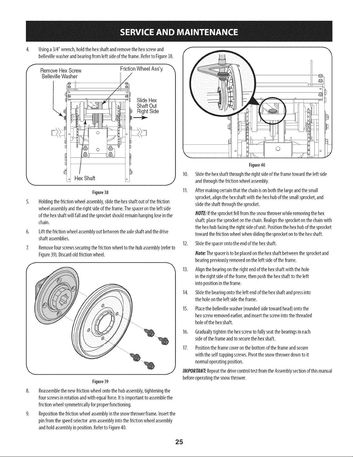
Usinga3/4" wrench,holdthehexshaftandremovethehexscrewand
bellevillewasherandbearingfromleft sideof theframe.Referto Figure38.
Remove Hex Screw
Belleville Washer
l.
HexShaft
FrictionWheel Ass'y.
/
i Slide Hex
Shaft Out
I Right Side
J
Figure38
Holdingthe frictionwheelassembly,slidethe hexshaftoutofthefriction
wheelassemblyandtheright sideoftheframe.Thespaceron the left side
ofthe hexshaftwill fall andthe sprocketshouldremainhangingloseinthe
chain.
Lift thefrictionwheelassemblyout betweentheaxleshaftandthedrive
shaftassemblies.
Removefour screwssecuringthe frictionwheeltothe hubassembly(referto
Figure39).Discardold frictionwheel.
J
Figure39
Reassemblethe newfrictionwheelontothehubassembly,tighteningthe
fourscrewsinrotationandwith equalforce.It isimportantto assemblethe
frictionwheelsymmetricallyfor properfunctioning.
Repositionthe frictionwheelassemblyinthesnowthrowerframe.Insertthe
pinfrom thespeedselectorarmassemblyinto thefrictionwheelassembly
andhold assemblyin position.Referto Figure40.
©
Figure40
10. Slidethehexshaftthroughtherightsideof theframetowardthe left side
andthroughthefrictionwheelassembly.
11. Aftermakingcertainthatthe chainisonboththe largeandthesmall
sprocket,alignthehexshaftwith the hexhubof the smallsprocket,and
slidetheshaftthroughthe sprocket.
NOTE:Ifthe sprocketfellfromthesnowthrowerwhileremovingthehex
shaft,placethe sprocketon thechain.Realignthe sprocketon thechainwith
thehexhubfacingtheright sideof unit.Positionthehexhubof thesprocket
towardthefrictionwheelwhenslidingthesprocketonto thehexshaft.
12. Slidethespacerontotheendof thehexshaft.
flete: Thespaceristo beplacedon the hexshaftbetweenthesprocketand
bearingpreviouslyremovedonthe left sideofthe frame.
13. Alignthebearingon the right endofthe hexshaftwith thehole
in therightsideof the frame,thenpushthehexshaftto theleft
into positionintheframe.
14. Slidethebearingontotheleft endofthe hexshaftandpressinto
theholeontheleft sidetheframe.
15.
16.
Placethe bellevillewasher(roundedsidetowardhead)ontothe
hexscrewremovedearlier,andinsertthescrewintothe threaded
holeof the hexshaft.
Graduallytighten the hexscrewto fullyseatthebearingsineach
sideof the frameandto securethe hexshaft.
17. Positionthe framecoveronthe bottomof theframeandsecure
with theself-tappingscrews.Pivotthesnowthrowerdownto it
normaloperatingposition.
IMPORTAfl#Repeatthedrivecontroltest fromthe Assemblysectionof thismanual
beforeoperatingthesnowthrower.
25
If thesnowthrowerwill notbeusedfor 30daysorlonger,or if it is theendof thesnowseasonwhenthe lastpossibilityof snowisgone,the equipmentneedsto bestored
properly.Followstorageinstructionsbelowto ensuretopperformancefromthesnowthrowerformanymoreyears.
PreparingEngine
Enginesstoredover30daysneedto bedrainedof fuel to preventdeteriorationand
gumfromformingin fuel systemor on essentialcarburetorparts.If thegasolinein
yourenginedeterioratesduringstorage,youmayneedto havethecarburetor,and
otherfuelsystemcomponents,servicedor replaced.
1. Removeall fuel fromtankbyrunningengineuntil it stops.Donotattemptto
pourfuelfrom theengine.
2. Changetheengineoil.
3. Removesparkplugandpourapproximately1oz.(30ml) ofcleanengineoil
into thecylinder.Pullthe recoilstarterseveraltimesto distributetheoil, and
reinstallthesparkplug.
4. Cleandebrisfromaroundengine,andunder,around,andbehindmuffler.
Applya lightfilm ofoil on anyareasthat aresusceptibleto rust.
Storeinaclean,dry andwell ventilatedareaawayfromanyappliancethat
operateswith aflameor pilot light,suchasa furnace,waterheater,or
clothesdryer.Avoidanyareawitha sparkproducingelectricmotor,orwhere
powertoolsareoperated.
If possible,avoidstorageareaswith highhumidity.
Keepthe enginelevelinstorage.Tiltingcancausefuelor oil leakage.
!
Neverstore snowthrower with fuel intank indoorsor in poorlyventilated J
areas,where fuel fumesmayreachan openflame, sparkor pilotlight ason aJ
I
fumace,water heater,c othesdryeror gasapp ante. j
PreparingSnowThrower
Whenstoringthe snowthrowerin anunventilatedormetalstorageshed,
careshouldbetakento rustprooftheequipment.Usinga lightoil orsilicone,
coattheequipment,especiallyanychains,springs,bearingsandcables.
Removeall dirt from exteriorof engineandequipment.
Followlubricationrecommendations.
Storeequipmentinaclean,dryarea.
Inflatethe tiresto themaximumPSI.Referto tire sidewall.
26
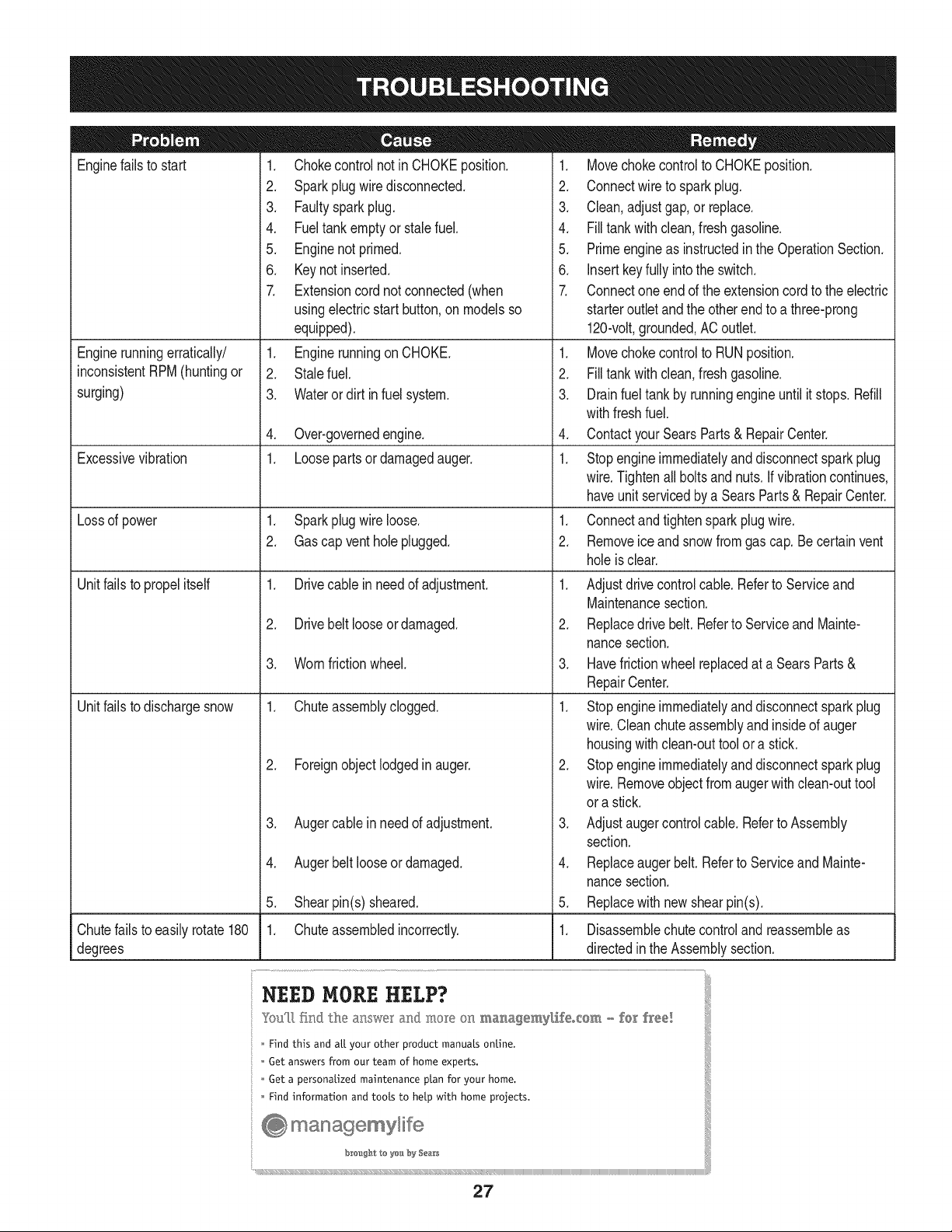
Enginefails to start
Enginerunningerratically/
inconsistentRPM(huntingor
surging)
Excessivevibration
Lossof power
Unitfailsto propelitself
Unitfailsto dischargesnow
1. Chokecontrolnot in CHOKEposition.
2. Sparkplugwire disconnected.
3. Faultysparkplug.
4. Fueltank emptyor stalefuel.
5. Enginenot primed.
6. Keynot inserted.
7. Extensioncordnot connected(when
usingelectricstartbutton,on modelsso
equipped).
1. Enginerunningon CHOKE.
2. Stalefuel.
3. Wateror dirt in fuel system.
4. Over-governedengine.
1. Loosepartsor damagedauger.
1. Sparkplugwire loose.
2. Gascap vent hole plugged.
1. Drivecable in need of adjustment.
2. Drivebelt looseor damaged.
3. Wornfrictionwheel.
1. Chuteassemblyclogged.
2. Foreignobject lodgedin auger.
3. Augercablein needof adjustment.
4. Augerbelt looseordamaged.
5. Shearpin(s) sheared.
1. Chuteassembledincorrectly.
1. Movechokecontrolto CHOKEposition.
2. Connectwireto sparkplug.
3. Clean,adjustgap,or replace.
4. Filltank with clean,freshgasoline.
5. Primeengineas instructedin the OperationSection.
6. Insertkeyfully intothe switch.
7. Connectone end of the extensioncordto the electric
starteroutletand the otherend to a three-prong
120-volt,grounded,ACoutlet.
1. Movechokecontrolto RUNposition.
2. Filltank with clean,freshgasoline.
3. Drainfueltankby runningengineuntil it stops. Refill
withfreshfuel.
4. ContactyourSearsParts& RepairCenter.
1. Stopengineimmediatelyand disconnectsparkplug
wire.Tightenall boltsand nuts.Ifvibrationcontinues,
haveunit servicedbya SearsParts& RepairCenter.
1. Connectand tightenspark plugwire.
2. Removeiceand snowfromgascap. Be certainvent
holeis clear.
1. Adjustdrivecontrolcable.Referto Serviceand
Maintenancesection.
2. Replacedrive belt. Referto Serviceand Mainte-
nancesection.
3. Havefrictionwheelreplacedat a SearsParts&
RepairCenter.
1. Stopengineimmediatelyand disconnectsparkplug
wire.Cleanchute assemblyand insideof auger
housingwithclean-outtoolor a stick.
2. Stopengineimmediatelyand disconnectsparkplug
wire.Removeobjectfromaugerwith clean-outtool
ora stick.
3. Adjustaugercontrolcable. Referto Assembly
section.
4. Replaceauger belt. Referto Serviceand Mainte-
nancesection.
5. Replacewith newshearpin(s).
Chutefailsto easilyrotate180 1. Disassemblechutecontroland reassembleas
degrees directedinthe Assemblysection.
NEED HORE HELP?
Yot,Fttfind. th_ answer a!ld mo_e on ma_age_y_ifeocom _ for free]
Find this and att your other product manua[s ontine.
Get answers from our team of home experts.
Get a personalized maintenance p[an for your home.
Find information and tools to he[p with home projects.
managemylife
b_e'_g_t_/_eyeu by Sea_s
27
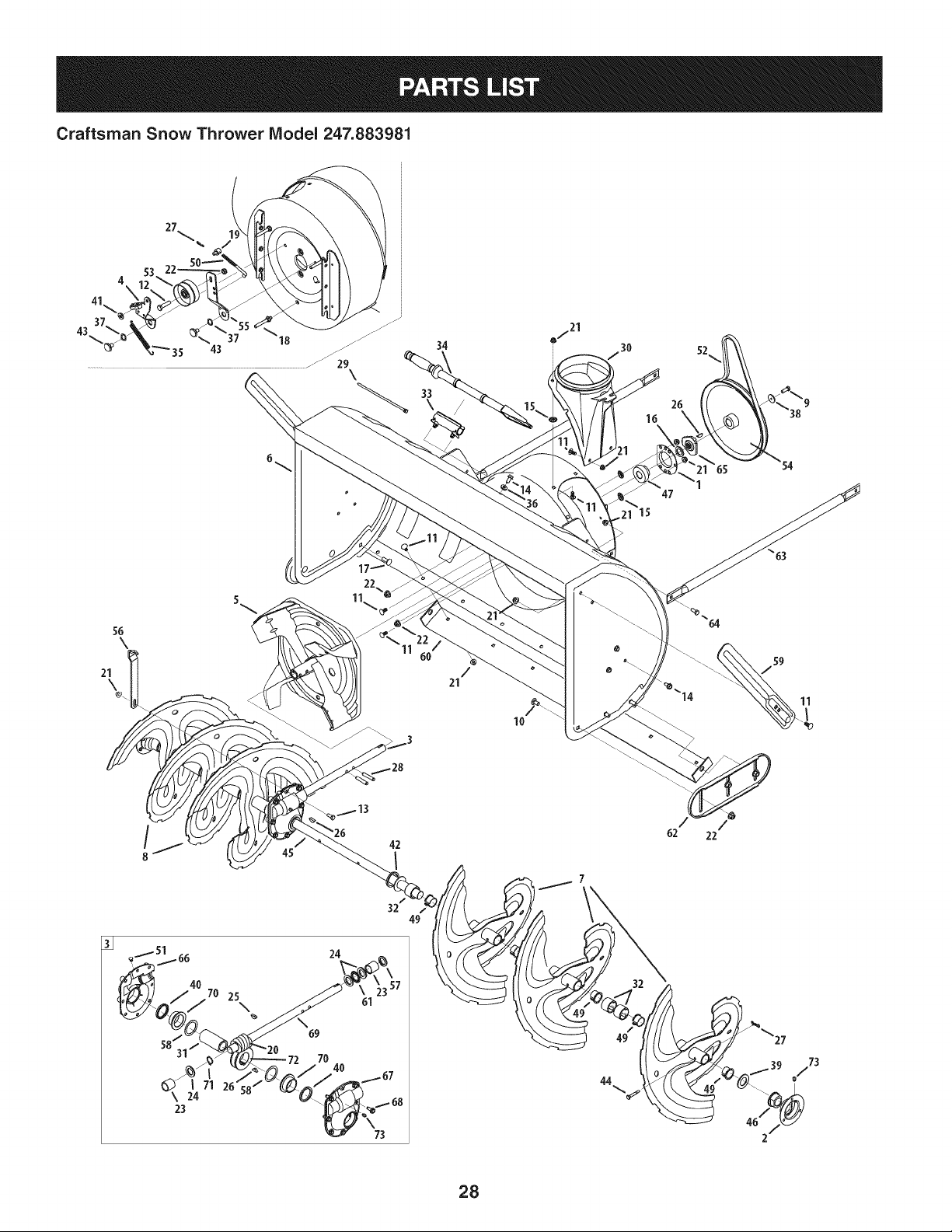
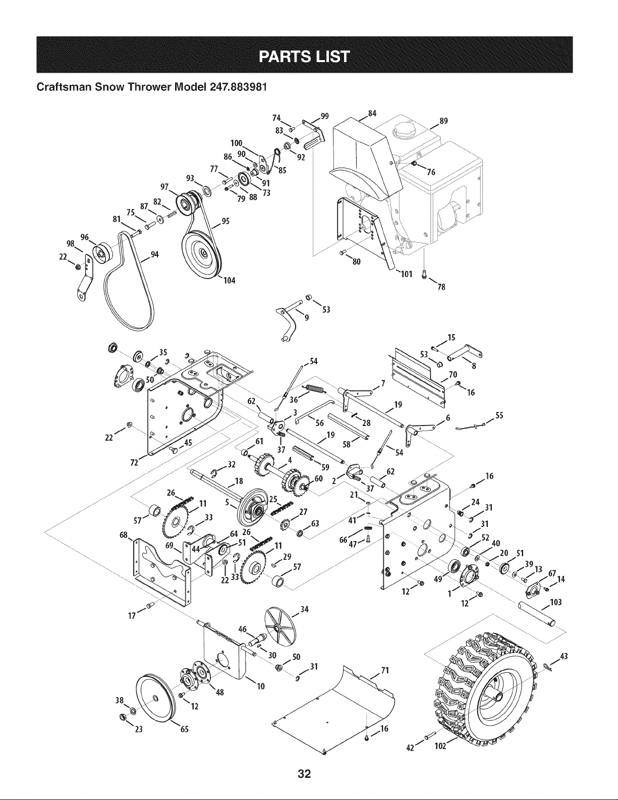
Craftsman Snow Thrower IViodel 247.883981
34
67 21
/ 30 52,.,
16
26
38
"15
47
56
\
21
\
/
21
lO
59
11
26
42
I
62 22
\ 24
23
7O 25
\
24
69
70
61
49
32
44
73
28
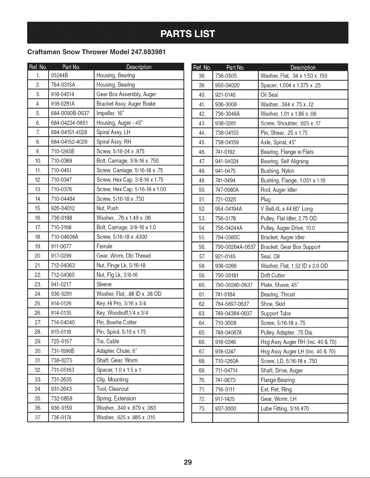
Craftsman Snow Thrower IViodel 247.883981
D = 0
05244B Housing,Bearing
2. 784-0315A Housing,Bearing
3. 918-04514 GearBoxAssembly,Auger
4. 918-0281A BracketAssy,Auger Brake
5. 684-0090B-0637 Impellar,16"
6. 684-04224-0691 Housing,Auger- 45"
7. 684-04151-4028 SpiralAssy,LH
8. 684-04152-4028
9. 710-1245B
10. 710-0389
11. 710-0451
12. 710-0347
13. 710-0376
14. 710-04484
SpiralAssy,RH
Screw,5/16-24x .875
Bolt,Carriage,3/8-16x .750
Screw,Carriage,5/16-18x .75
Screw,HexCap,3/8-16x 1.75
Screw,HexCap,5/16-18x 1.00
Screw,5/16-18x .750
15. J 926-04012 _Nut, Push
16. 736-0188 Washer,..76x 1.49x .06
17. 710-3168 Bolt,Carriage,3/8-16x 1.0
18. 710-04606A Screw,5/16-18x .4300
19. 911-0677 Ferrule
20. 917-0299 Gear,Worm,DblThread
21. 712-04063 Nut,FlngeLk, 5/16-18
22. 712-04065 Nut,Fig Lk,3/8-16
23. 941-0217 Sleeve
24. 936-0291 Washer,Flat,.88 IDx .38 OD
25. 914-0126 Key,Hi Pro,3/16 x 3/4
26. 914-0135 Key,Woodruff,I/4 x 3/4
27. 714-04040 Pin,BowtieCotter
28. 915-0118 Pin,Spirol,5/16 x 1.75
29. 725-0157 Tie, Cable
30. 731-1696B Adapter,Chute,6"
31. 738-0275 Shaft,Gear,Worm
32. 731-05163 Spacer,1.0x 1.5x 1
33. 731-2635 Clip,Mounting
34. 931-2643 Tool,Cleanout
35. 732-0858 Spring,Extension
36. 936-0159 Washer,.349x .879x .063
37. 736-0174 Washer,.625x .885x .015
D = W O
736-0505 Washer,Flat,.34x 1.50x .150
39. 950-04020 Spacer,1.004x 1.375x .25
40. 921-0146 Oil Seal
41. 936-3008 Washer,.344x .75x .12
42. 736-3046A Washer,1.01x 1.86x .06
43. 938-0281 Screw,Shoulder,.625x .17
44. 738-04155 Pin, Shear,.25x 1.75
45. 738-04159 Axle,Spiral,45"
46. 741-0192 Bearing,Flangew/Flats
47. 941-04024 Bearing,SelfAligning
48. 941-0475 Bushing,Nylon
49. 741-0494 Bushing,Flange,1.051x 1.16
50. 747-0980A Rod,AugerIdler
51. 721-0325 Plug
52. 954-04194A V Belt,4Lx 44.60"Long
53. 756-0178 Pulley,FlatIdler,2.75OD
54. 756-04244A Pulley,Auger Drive,10.0
55. 784-0385C Bracket,AugerIdler
56. 790-00264A-0637 Bracket,GearBox Support
57. 921-0145 Seal,Oil
58. 936-0266 Washer,Flat,1.52ID x 2.00D
59. 790-00181 Drift Cutter
60. 790-00280-0637 Plate,Shave,45"
61. 741-0184 Bearing,Thrust
62. 784-5697-0637 Shoe,Skid
63. 749-04384-0637 SupportTube
64. 710-3008 Screw,5/16-18x .75
65. 748-04067A Pulley,Adapter,.75Dia.
66. 918-0246 HsgAssyAuger RH (Inc.40 &70)
67. 918-0247 HsgAssyAugerLH(Inc.40 & 70)
68. 710-1260A Screw,LD,5/16-18x .750
69. 711-04714 Shaft, Drive,Auger
70. 741-0670 FlangeBearing
71. 716-0111 Ext, Ret, Ring
72. 917-1425 Gear,Worm,LH
73. 937-3000 LubeFitting,3/16#70
29
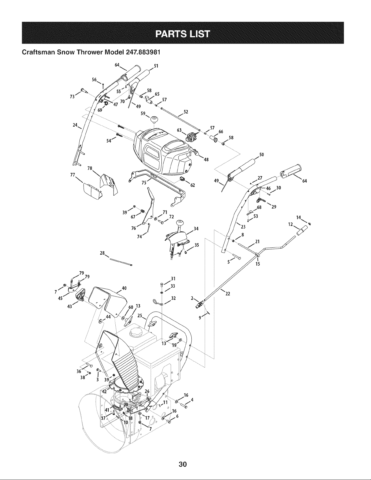
Craftsman Snow Thrower Model 247.883981
64 sl
56
52
79
79
43 /
//
,/
21
15
13
31
_/33
32
3O
\
3O
|- ot |- o_
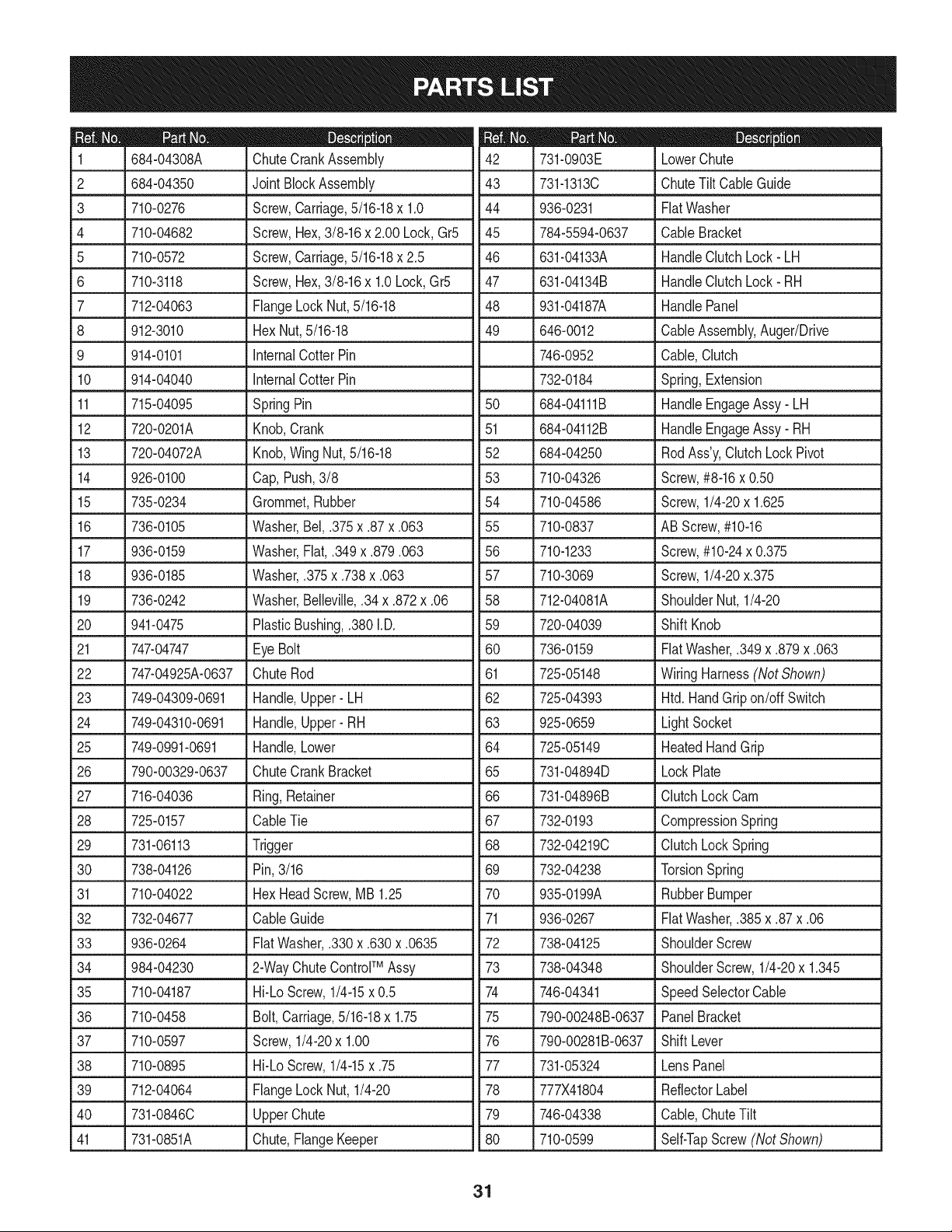
684-04308A ChuteCrankAssembly 731-0903E LowerChute
2 684-04350 JointBlockAssembly 43 731-1313C ChuteTiltCableGuide
710-0276
710-04682
710-0572
710-3118
712-04063
912-3010
914-0101
Screw,Carriage,5/16-18x 1.0
Screw,Hex,3/8-16x 2.00 Lock,Gr5
Screw,Carriage,5/16-18x 2.5
Screw,Hex,3/8-16x 1.0Lock,Gr5
FlangeLock Nut,5/16-18
Hex Nut,5/16-18
internalCotterPin
3
4
5
6
7
8
9
44 936-0231 FiatWasher
45 784-5594-0637 CableBracket
46 631-04133A HandleClutchLock- LH
47 631-04134B HandleClutchLock- RH
48 931-04187A HandlePanel
49 646-0012 CableAssembly,Auger/Drive
746-0952 Cable,Clutch
10 914-04040 _internalCotterPin _732-0184 Spring,Extension
11 715-04095 SpringPin
12 720-0201A Knob,Crank
13 720-04072A Knob,WingNut,5/16-18
14 926-0100 Cap,Push,3/8
15 735-0234 Grommet,Rubber
16 736-0105 Washer,Bel,.375x .87x .063
17 936-0159 Washer,Fiat,.349x .879.063
18 936-0185 Washer,.375x .738x .063
19 736-0242 Washer,Belleville,.34x .872x .06
20 941-0475 PlasticBushing,.380I.D.
21 747-04747 Eye Bolt
22 747-04925A-0637 ChuteRod
23 749-04309-0691 Handle,Upper- LH
24 749-04310-0691 Handle,Upper- RH
25 749-0991-0691 Handle,Lower
26 790-00329-0637 ChuteCrankBracket
27 716-04036 Ring,Retainer
28 725-0157 CableTie
29 731-06113 Trigger
30 738-04126 Pin, 3/16
31 710-04022 Hex HeadScrew,MB 1.25
32 732-04677 CableGuide
33 936-0264 FiatWasher,.330x .630x .0635
34 984-04230 2-WayChuteControlTM Assy
50 684-04111B HandleEngageAssy- LH
51 684-04112B HandleEngageAssy- RH
52 684-04250 RodAss'y,ClutchLock Pivot
53 710-04326 Screw,#8-16x 0.50
54 710-04586 Screw,1/4-20x 1.625
55 710-0837 ABScrew,#10-16
56 710-1233 Screw,#10-24x 0.375
57 710-3069 Screw,1/4-20x.375
58 712-04081A ShoulderNut,1/4-20
59 720-04039 ShiftKnob
60 736-0159 FiatWasher,.349x .879x .063
61 725-05148 WiringHarness(Not Shown)
62 725-04393 Htd. HandGripon/off Switch
63 925-0659 LightSocket
64 725-05149 HeatedHandGrip
65 731-04894D LockPlate
66 731-04896B ClutchLockCam
67 732-0193 CompressionSpring
68 732-04219C ClutchLockSpring
69 732-04238 TorsionSpring
70 935-0199A RubberBumper
71 936-0267 FiatWasher,.385x .87x .06
72 738-04125 ShoulderScrew
73 738-04348 ShoulderScrew,1/4-20x 1.345
35 710-04187 Hi-Lo Screw,1/4-15x 0.5
36 710-0458 Bolt,Carriage,5/16-18x 1.75
37 710-0597 Screw,1/4-20x 1.00
38 710-0895 Hi-Lo Screw,1/4-15x .75
39 712-04064 FlangeLock Nut, 1/4-20
40 731-0846C UpperChute
41 731-0851A Chute,FlangeKeeper
74 746-04341 SpeedSelectorCable
75 790-00248B-0637 PanelBracket
76 790-00281B-0637 ShiftLever
77 731-05324 LensPanel
78 777X41804 ReflectorLabel
79 746-04338 Cable,ChuteTilt
80 710-0599 Self-TapScrew (Not Shown)
31
Craftsman Snow Thrower IViodel 247.883981
81
100
8Q
77
53
_101
78
35
26
11
37
27
/7
15
7O
55
/
/24 31
31
51
71
1 /
12
32
Craftsman Snow Thrower IViodel 247.883981
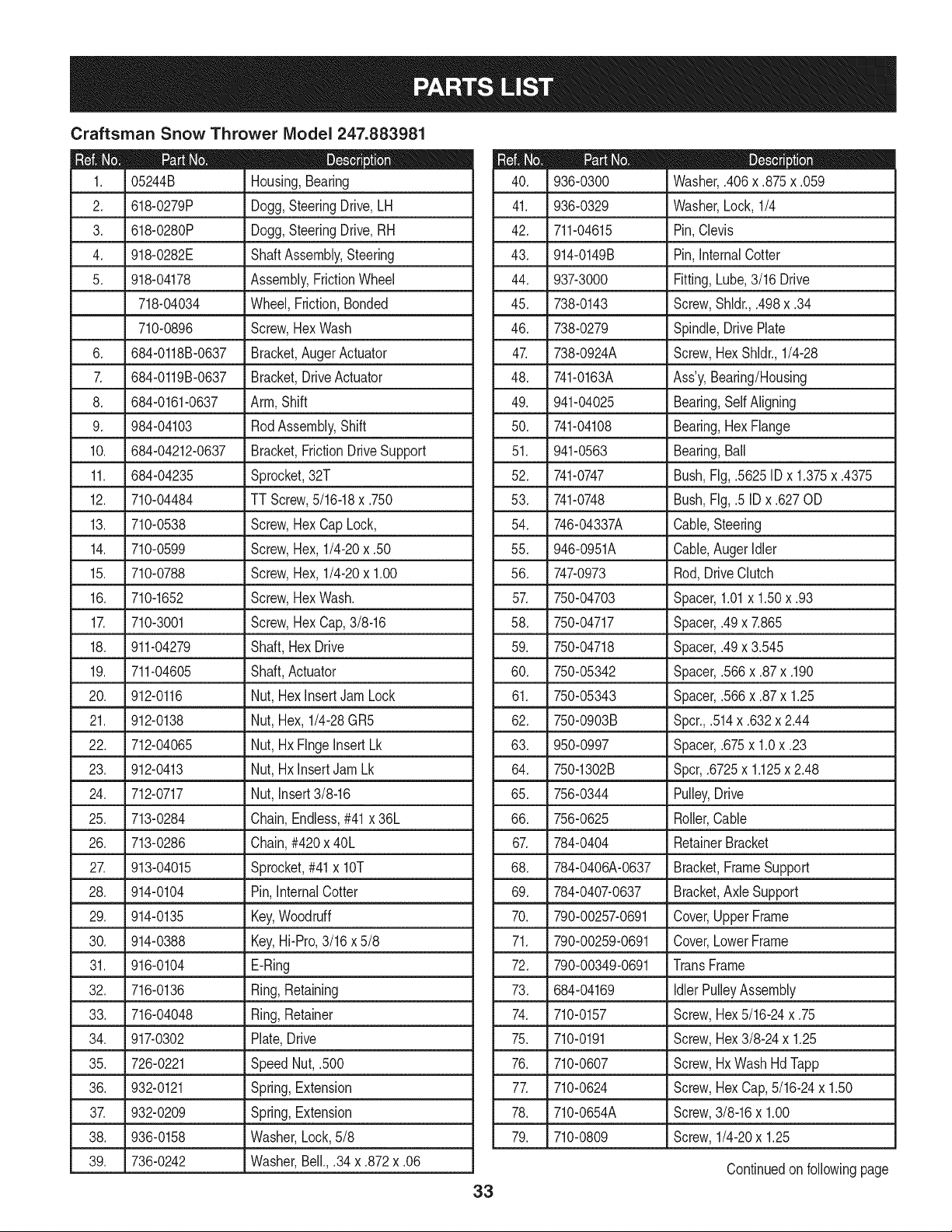
,
3.
4.
5.
05244B
618-0279P
618-0280P
918-0282E
918-04178
718-04034
Housing,Bearing
Dogg,SteeringDrive,LH
Dogg,SteeringDrive,RH
ShaftAssembly,Steering
Assembly,FrictionWheel
Wheel,Friction,Bonded
710-0896 Screw,HexWash
6. 684-0118B-0637 Bracket,Auger Actuator
7. 684-0119B-0637 Bracket,DriveActuator
8. 684-0161-0637 Arm,Shift
9. 984-04103 RodAssembly,Shift
10. 684-04212-0637 Bracket,FrictionDriveSupport
11. 684-04235 Sprocket,32T
12. 710-04484 J TT Screw,5/16-18x .750
13. 710-0538 Screw,HexCap Lock,
14. 710-0599 Screw,Hex, 1/4-20x .50
15. 710-0788 Screw,Hex, 1/4-20x 1.00
16. 710-1652 Screw,HexWash.
17. 710-3001 Screw,HexCap,3/8-16
18. 911-04279 Shaft, HexDrive
19. 711-04605 Shaft,Actuator
20. 912-0116 Nut, HexinsertJam Lock
21. 912-0138 Nut, Hex,1/4-28GR5
22. 712-04065 Nut, HxFlngeinsertLk
23. 912-0413 Nut, HxinsertJamLk
24. 712-0717 Nut, insert3/8-16
25. 713-0284 Chain,Endless,#41x 36L
26. 713-0286 Chain,#420x 40L
27. 913-04015 Sprocket,#41 x lOT
28. 914-0104 Pin, InternalCotter
D = O O
936-0300 Washer,.406x .875x .059
41. 936-0329 Washer,Lock, 1/4
42. 711-04615 Pin,Clevis
43. 914-0149B Pin,InternalCotter
44. 937-3000 Fitting,Lube,3/16 Drive
45. 738-0143 Screw,Shldr.,.498x .34
46. 738-0279 Spindle,DrivePlate
47. 738-0924A Screw,HexShldr.,1/4-28
48. 741-0163A Ass'y, Bearing/Housing
49. 941-04025 Bearing,SelfAligning
50. 741-04108 Bearing,HexFlange
51. 941-0563 Bearing,Ball
52. 741-0747 Bush,Fig,.5625ID x 1.375x .4375
53. 741-0748 Bush,Fig,.5 ID x .627OD
54. 746-04337A Cable,Steering
55. 946-0951A Cable,AugerIdler
56. 747-0973 Rod,DriveClutch
57. 750-04703 Spacer,1.01x 1.50x .93
58. 750-04717 Spacer,.49x 7.865
59. 750-04718 Spacer,.49x 3.545
60. 750-05342 Spacer,.566x .87x .190
61. 750-05343 Spacer,.566x .87x 1.25
62. 750-0903B Spcr.,.514x .632x 2.44
63. 950-0997 Spacer,.675x 1.0x .23
64. 750-1302B Spcr,.6725x 1.125x 2.48
65. 756-0344 Pulley,Drive
66. 756-0625 Roller,Cable
67. 784-0404 RetainerBracket
68. 784-0406A-0637 Bracket,FrameSupport
69. 784-0407-0637 Bracket,Axle Support
29. 914-0135 Key,Woodruff
30. 914-0388 Key,Hi-Pro,3/16x 5/8
31. 916-0104 •E-Ring
32. 716-0136 Ring,Retaining 73.
33. 716-04048 Ring,Retainer 74.
34. 917-0302 Plate,Drive 75.
35. 726-0221 SpeedNut,.500 76.
36. _9320121 Spring,Extension 77.
37. 932-0209 Spring,Extension 78.
38. 936-0158 Washer,Lock,5/8 79.
39. 736-0242 Washer,Bell.,.34 x .872x .06
33
70. 790-00257-0691 Cover,UpperFrame
71. 790-00259-0691 Cover,LowerFrame
72. 790-00349-0691 TransFrame
684-04169 IdlerPulleyAssembly
710-0157 Screw,Hex5/16-24x .75
710-0191 Screw,Hex3/8-24 x 1.25
710-0607 Screw,HxWashHd Tapp
710-0624 Screw,HexCap,5/16-24x 1.50
710-0654A Screw,3/8-16x 1.00
710-0809 Screw,1/4-20x 1.25
Continuedon followingpage
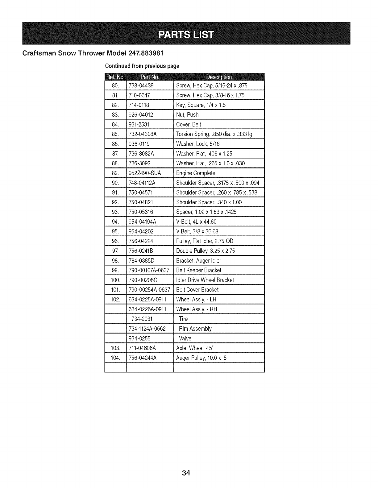
Craftsman Snow Thrower IViodel 247.883981
81. 710-0347
82. 714-0118
83. 926-04012
84. 931-2531
85. 732-04308A
86. 936-0119
8_ 736-3082A
88. 736-3092
Continuedfrom previouspage
D = 0 e
738-04439 Screw,HexCap,5/16-24x .875
Screw,HexCap,3/8-16x 1.75
Key,Square,1/4x 1.5
Nut, Push
Cover,Belt
TorsionSpring,.850dia. x .333Ig.
Washer,Lock,5/16
Washer,Fiat,.406x 1.25
Washer,Fiat,.265x 1.0x .030
89. 952Z490-SUA EngineComplete
90. 748-04112A ShoulderSpacer,.3175x .500x .094
91. 750-04571 ShoulderSpacer,.260x .785x .538
92. 750-04821 ShoulderSpacer,.340x 1.00
93. 750-05316 Spacer,1.02x 1.63x .1425
94. 954-04194A V-Belt,4Lx 44.60
95. 954-04202 V Belt, 3/8 x 36.68
96. 756-04224 Pulley,Fiatidler,2.75 OD
97. 756-0241B DoublePulley,3.25x 2.75
98. 784-0385D Bracket,Auger idler
99. 790-00167A-0637 Belt KeeperBracket
100. 790-00208C idler DriveWheelBracket
101. 790-00254A-0637 Belt CoverBracket
102. 634-0225A-0911 WheelAss'y.- LH
634-0226A-0911 WheelAss'y.- RH
734-2031 Tire
734-1124A-0662 RimAssembly
934-0255 Valve
103. 711-04606A Axle,Wheel,45"
104. 756-04244A AugerPulley,10.0x .5
34
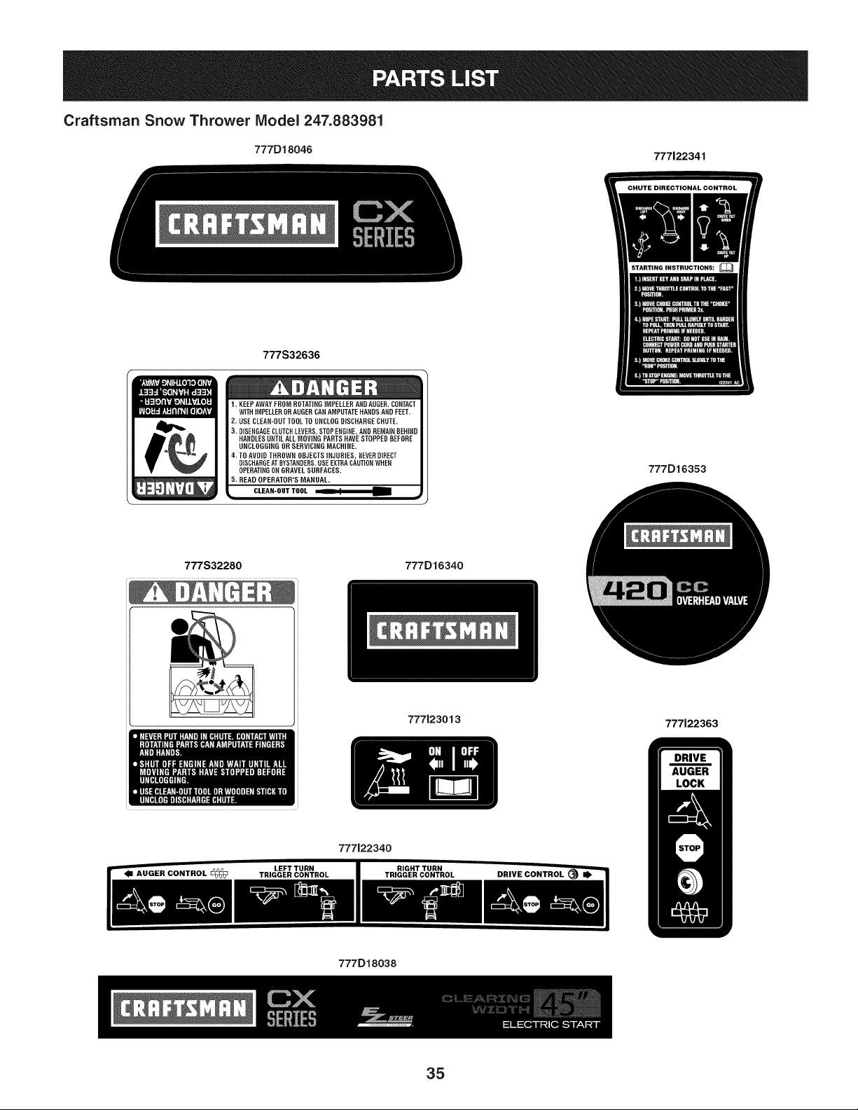
Craftsman Snow Thrower IViodel 247.883981
777D18046 777122341
777S32636
l. EEP AWAY FROM ROTATING IMPELLER AND AUGER. CONTACT
WITH IMPELLER OR AUGERCAN AMPUTATE HANDS AND FEET.
2. USE CLEAN-OUT TOOL TO UNCLOG DISCHARGE CHUTE.
3. DISENGAGECLUTCH LEVERS,STOP ENGINE,AND REMAINBEHIND
HANDLES UNTIL ALL MOVING PARTS HAVE STOPPED BEFORE
UNCLOGGING OR SERVICING MACHINE.
4. TO AVOID THROWN OBJECTS INJURIES, NEVERDIRECT
DISCHARGEAT BYSTANDERS.USE EXTRACAUTIONWHEN
OPERATINGON GRAVEL SURFACES.
5. READ OPERATOR'S MANUAL.
CLEAN-OUT TOOL _ =4
777D16353
777S32280 777D16340
777123013
777122363
777122340
777D18038
35
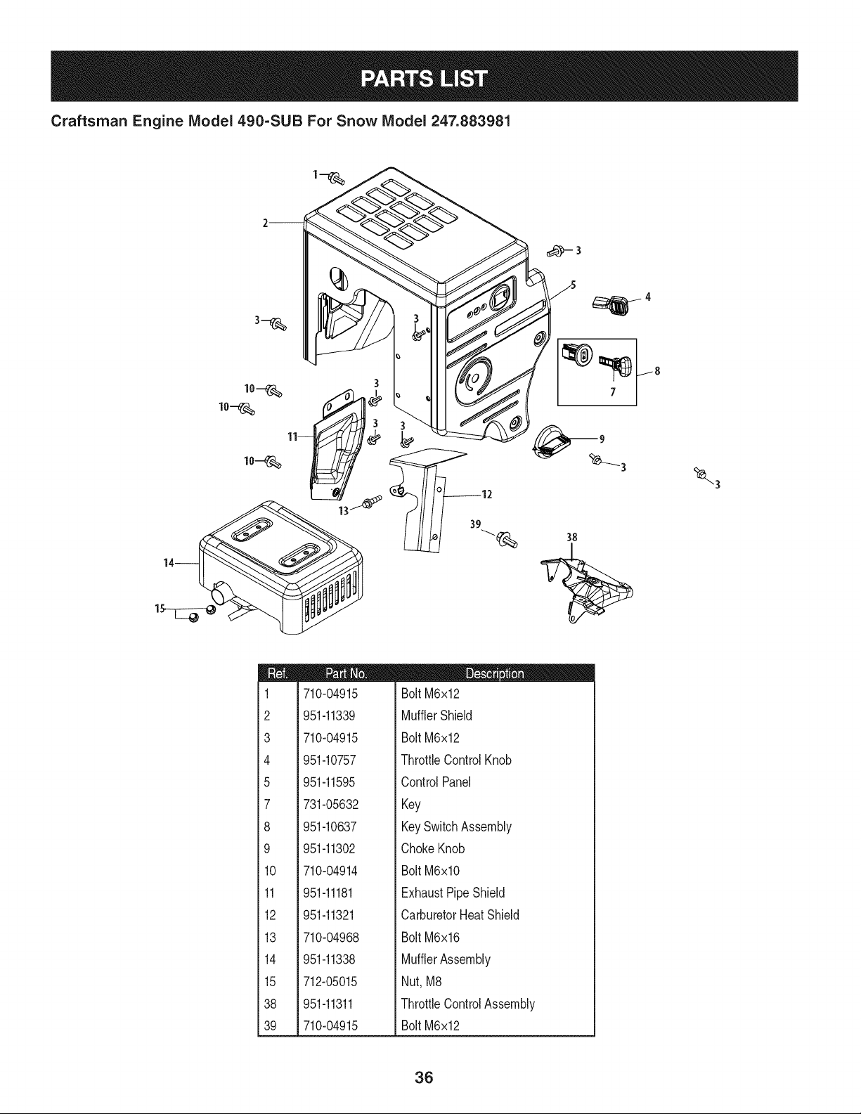
Craftsman Engine Model 490=SUB For Snow Model 247.883981
m
1
2
3
4
5
7
8
9
10
11
12
13
14
15
38
39
710-04915
951-11339
710-04915
951-10757
951-11595
731-05632
951-10637
951-11302
710-04914
951-11181
951-11321
710-04968
951-11338
712-05015
951-11311
710-04915
D = I! II
Bolt M6x12
MufflerShield
Bolt M6x12
ThrottleControlKnob
ControlPanel
Key
KeySwitchAssembly
ChokeKnob
Bolt M6xlO
ExhaustPipeShield
CarburetorHeatShield
Bolt M6x16
MufflerAssembly
Nut, M8
ThrottleControlAssembly
Bolt M6x12
36
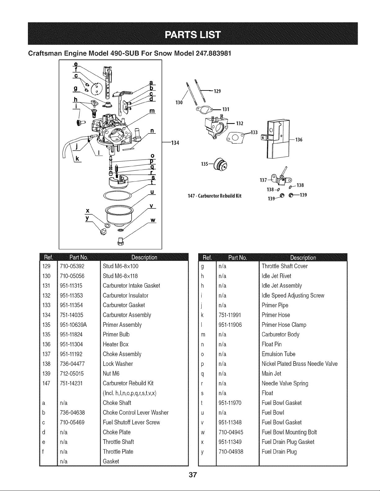
Craftsman Engine IViodel 490-SUB For Snow IViodel 247.883981
X
Y
V
130
--134
_131
33
147- CarburetorRebuildKit
137138_0_ 138
139_ 0--139
m
129
130
131
132
133
134
135
135
136
137
138
139
147
a
b
C
d
e
f
710-05392
710-05056
951-11315
951-11353
951-11354
751-14035
951-10639A
951-11824
951-11304
951-11192
736-04477
712-05015
751-14231
n/a
736-04638
710-05469
n/a
n/a
n/a
n/a
D = O
StudM6-8x100
StudM6-8x118
CarburetorIntakeGasket
CarburetorInsulator
CarburetorGasket
CarburetorAssembly
PrimerAssembly
PrimerBulb
HeaterBox
ChokeAssembly
LockWasher
NutM6
CarburetorRebuildKit
(Incl.h,l,n,o,p,q,r,s,t,v,x)
ChokeShaft
ChokeControlLeverWasher
FuelShutoffLeverScrew
ChokePlate
ThrottleShaft
ThrottlePlate
Gasket
m
g
h
h
I
J
k
I
m
n
o
P
q
r
s
t
U
V
W
X
Y
n/a
n/a
n/a
n/a
n/a
751-11991
951-11906
n/a
n/a
n/a
n/a
n/a
n/a
n/a
951-11970
n/a
951-11348
710-04945
951-11349
710-04938
D = O e
ThrottleShaft Cover
IdleJet Rivet
IdleJet Assembly
IdleSpeedAdjustingScrew
PrimerPipe
PrimerHose
PrimerHoseClamp
CarburetorBody
FloatPin
EmulsionTube
NickelPlatedBrassNeedleValve
MainJet
NeedleValveSpring
Float
FuelBowlGasket
FuelBowl
FuelBowlGasket
FuelBowlMountingBolt
FuelDrainPlugGasket
FuelDrainPlug
37
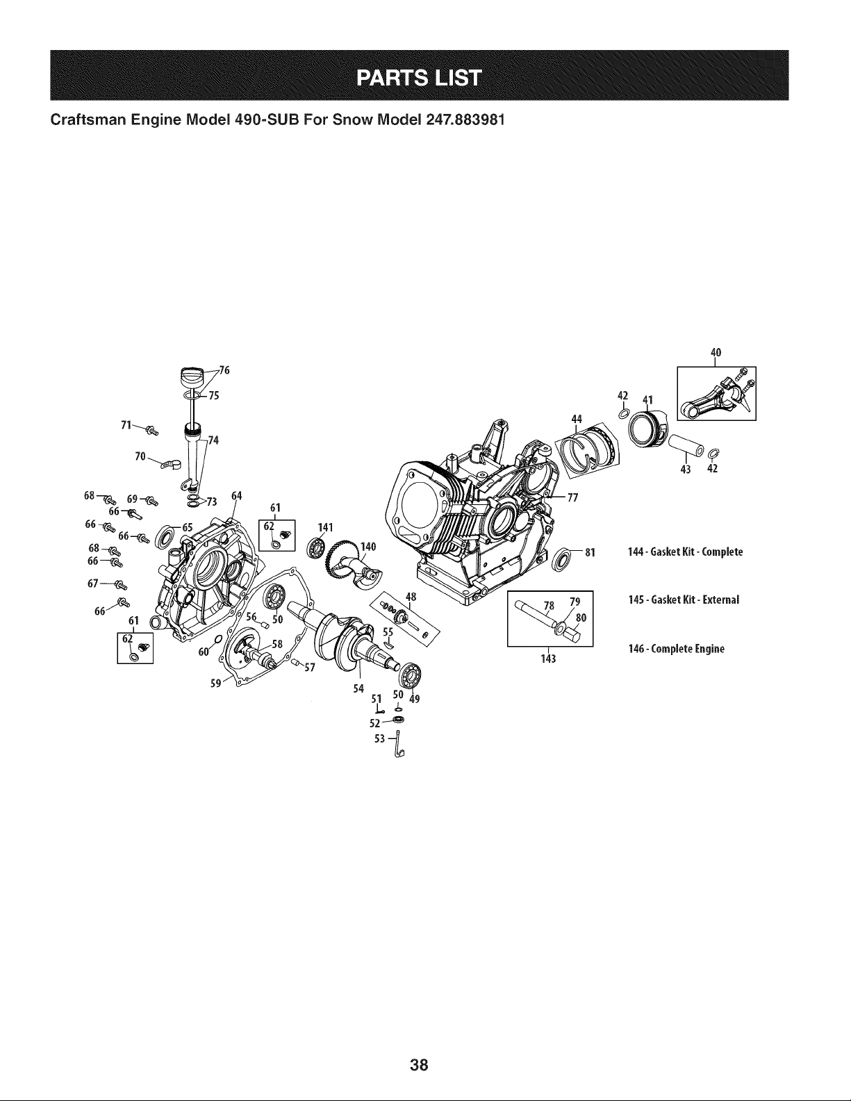
Craftsman Engine IViodel 490=SUB For Snow IViodel 247.883981
61
141
140
44
42
4O
I
43 42
144- GasketKit-Complete
145-GasketKit-External
146-CompleteEngine
49
38
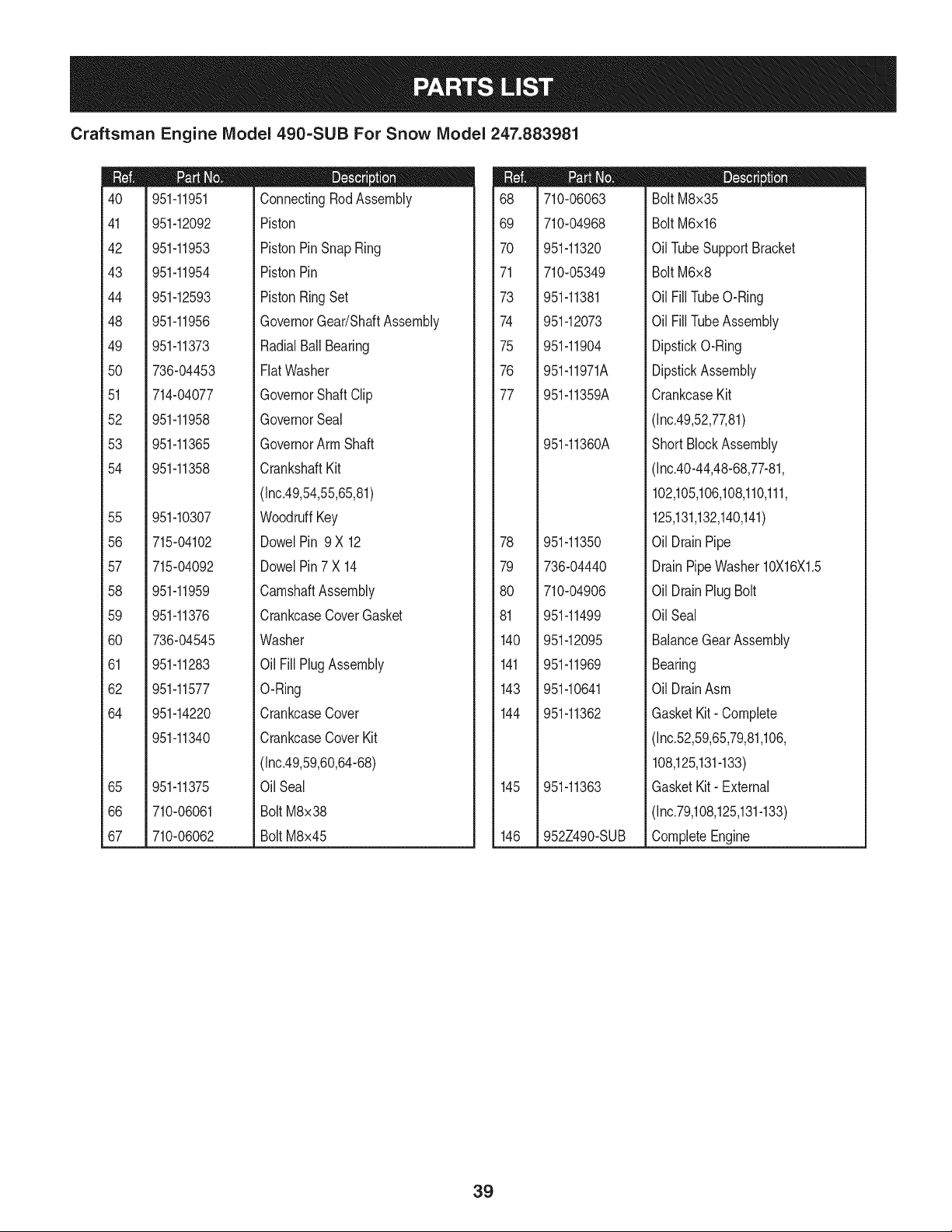
Craftsman Engine IViodel 490=SUB For Snow IViodel 247.883981
m
4O
41
42
43
44
48
49
5O
51
52
53
54
55
56
57
58
59
60
61
62
64
65
66
67
951-11951
951-12092
951-11953
951-11954
951-12593
951-11956
951-11373
736-04453
714-04077
951-11958
951-11365
951-11358
951-10307
715-04102
715-04092
951-11959
951-11376
736-04545
951-11283
951-11577
951-14220
951-11340
951-11375
710-06061
710-06062
m = O Q
ConnectingRodAssembly
Piston
PistonPinSnapRing
PistonPin
PistonRingSet
GovernorGear/ShaftAssembly
RadialBall Bearing
FlatWasher
GovernorShaftClip
GovernorSeal
GovernorArm Shaft
CrankshaftKit
(Inc.49,54,55,65,81)
WoodruffKey
DowelPin 9 X 12
DowelPin7 X 14
CamshaftAssembly
CrankcaseCoverGasket
Washer
Oil FillPlug Assembly
O-Ring
CrankcaseCover
CrankcaseCoverKit
(Inc.49,59,60,64-68)
Oil Seal
Bolt M8x38
Bolt M8x45
m
68
69
7O
71
73
74
75
76
77
78
79
8O
81
140
141
143
144
145
146
710-06063
710-04968
951-11320
710-05349
951-11381
951-12073
951-11904
951-11971A
951-11359A
951-11360A
951-11350
736-04440
710-04906
951-11499
951-12095
951-11969
951-10641
951-11362
951-11363
952Z490-SUB
D = W O
Bolt M8x35
Bolt M6x16
OilTubeSupportBracket
Bolt M6x8
Oil FillTubeO-Ring
Oil FillTubeAssembly
DipstickO-Ring
DipstickAssembly
CrankcaseKit
(Inc.49,52,77,81)
ShortBlockAssembly
(Inc.40-44,48-68,77-81,
102,105,106,108,110,111,
125,131,132,140,141)
Oil DrainPipe
DrainPipeWasher 10X16X1.5
Oil DrainPlug Bolt
OilSeal
BalanceGearAssembly
Bearing
Oil DrainAsm
GasketKit- Complete
(Inc.52,59,65,79,81,106,
108,125,131-133)
GasketKit- External
(Inc.79,108,125,131-133)
CompleteEngine
39
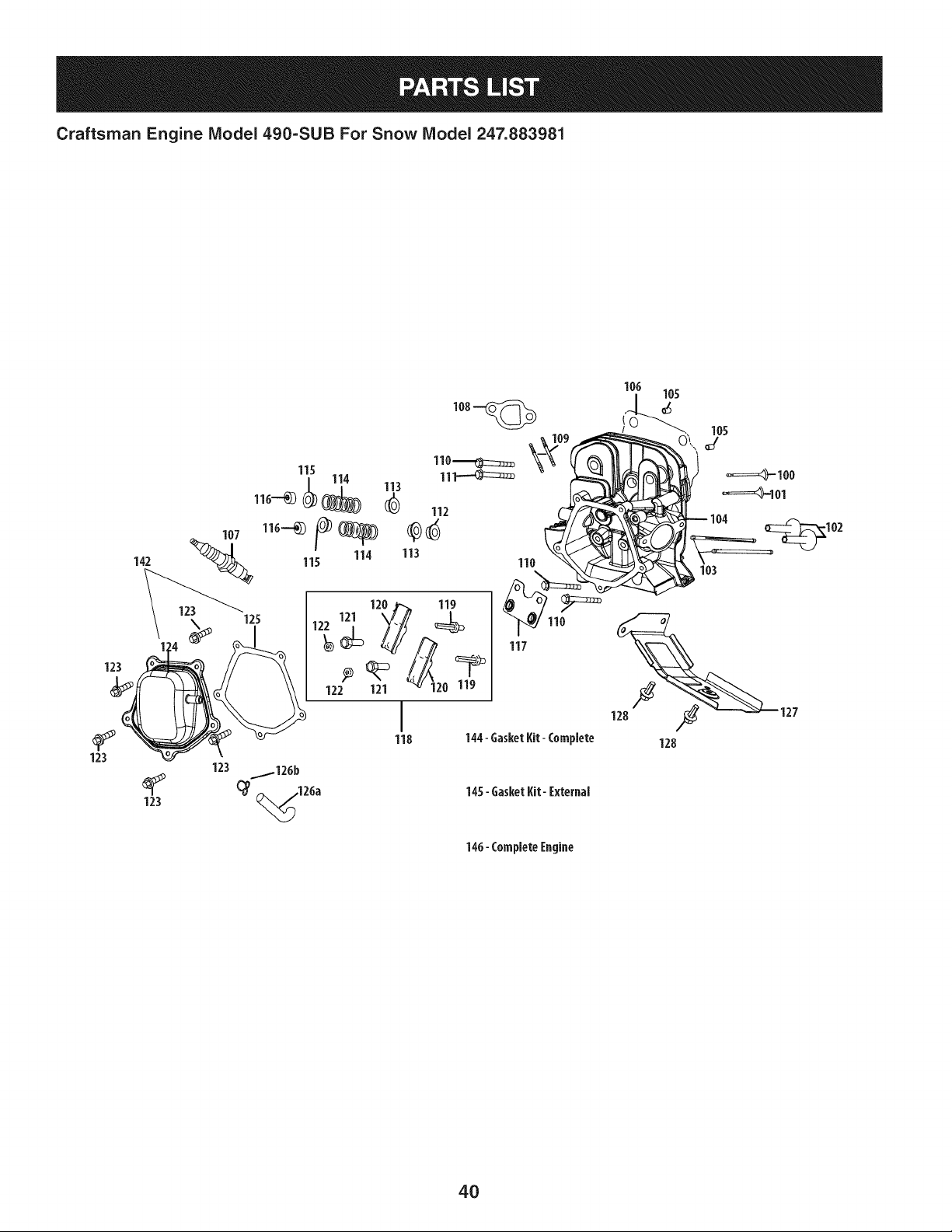
Craftsman Engine Model 490=SUB For Snow Model 247.883981
142
123
123
123
123 _126b
(_ ,126a 14S- GasketKit- [xternal
146- Complete[ngine
4O

Craftsman Engine IViodel 490-SUB For Snow IViodel 247.883981
m
1CO
101
102
103
104
105
106
107
108
109
109
110
111
112
113
114
115
951-11337
951-11337
951-11962
951-11335
951-12592
951-11361A
715-04097
951-12094
951-10292
951-11212
710-04964
951-11207
710-06064
710-06065
951-11964
951-12077
951-12078
951-12080
D = O 0
ValveKit
ValveKit
Tappet
PushRodKit
CylinderHeadKit
(Inc.106,110-112,125)
CylinderHeadAssembly
(Inc.100,101,104,106,108-112,
114-122,125,129-133)
DowelPin
CylinderHeadGasket
SparkPlug/F6Rtc
MufflerGasket
ExhaustStudM8x48.5
MufflerStudAssembly
BoltM10x1.25x87
BoltM10x1.25x65
IntakeValveSeal
IntakeValveSpringRetainer
ValveSpring
ExhaustValveSpringRetainer
m
116
117
118
119
120
121
122
123
124
125
126a
126b
127
128
142
144
145
146
951-12081
951-11965
951-11981
710-04962
951-11966
751-11123
751-11124
710-05054
951-11220
951-11967
731-07059
726-04101
951-11317
710-04915
951-11333
951-11362
951-11363
952Z490-SUB
D = O O
ExhaustLashCap
PushRodGuide
RockerArmAssembly
Bolt,Pivot
RockerArm
AdjustingNut,Valve
PivotLockingNut
ValveCoverBolt
ValveCover
ValveCoverGasket
BreatherHose
BreatherHoseClamp
CylinderBaffle
BoltM6x12
ValveCoverKit
GasketKit- Complete
(Inc.52,59,65,79,81,106,
108,125,131-133)
GasketKit- External
(Inc.79,108,125,131-133)
CompleteEngine
41
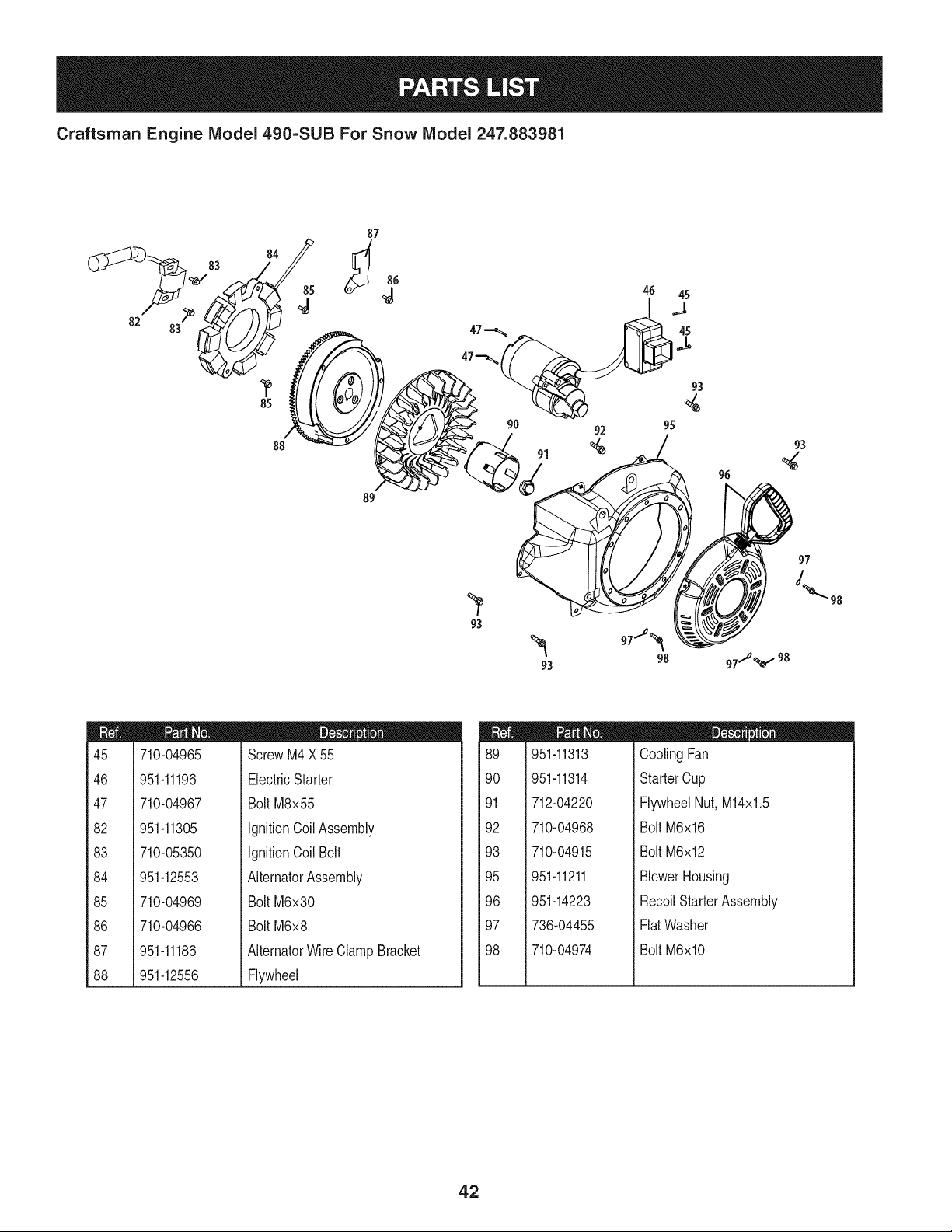
Craftsman Engine IViodel 490=SUB For Snow IViodel 247.883981
82
83
8s /
8
/
89
98
m
45
46
47
82
83
84
85
86
87
88
710-04965
951-11196
710-04967
951-11305
710-05350
951-12553
710-04969
710-04966
951-11186
951-12556
D = O
ScrewM4X 55
ElectricStarter
Bolt M8x55
IgnitionCoilAssembly
IgnitionCoil Bolt
AlternatorAssembly
Bolt M6x30
Bolt M6x8
AlternatorWireClamp Bracket
Flywheel
m
89
90
91
92
93
95
96
97
98
951-11313
951-11314
712-04220
710-04968
710-04915
951-11211
951-14223
736-04455
710-04974
D = O
CoolingFan
StarterCup
FlywheelNut, M14x1.5
Bolt M6x16
Bolt M6x12
BlowerHousing
RecoilStarterAssembly
FlatWasher
Bolt M6xlO
42
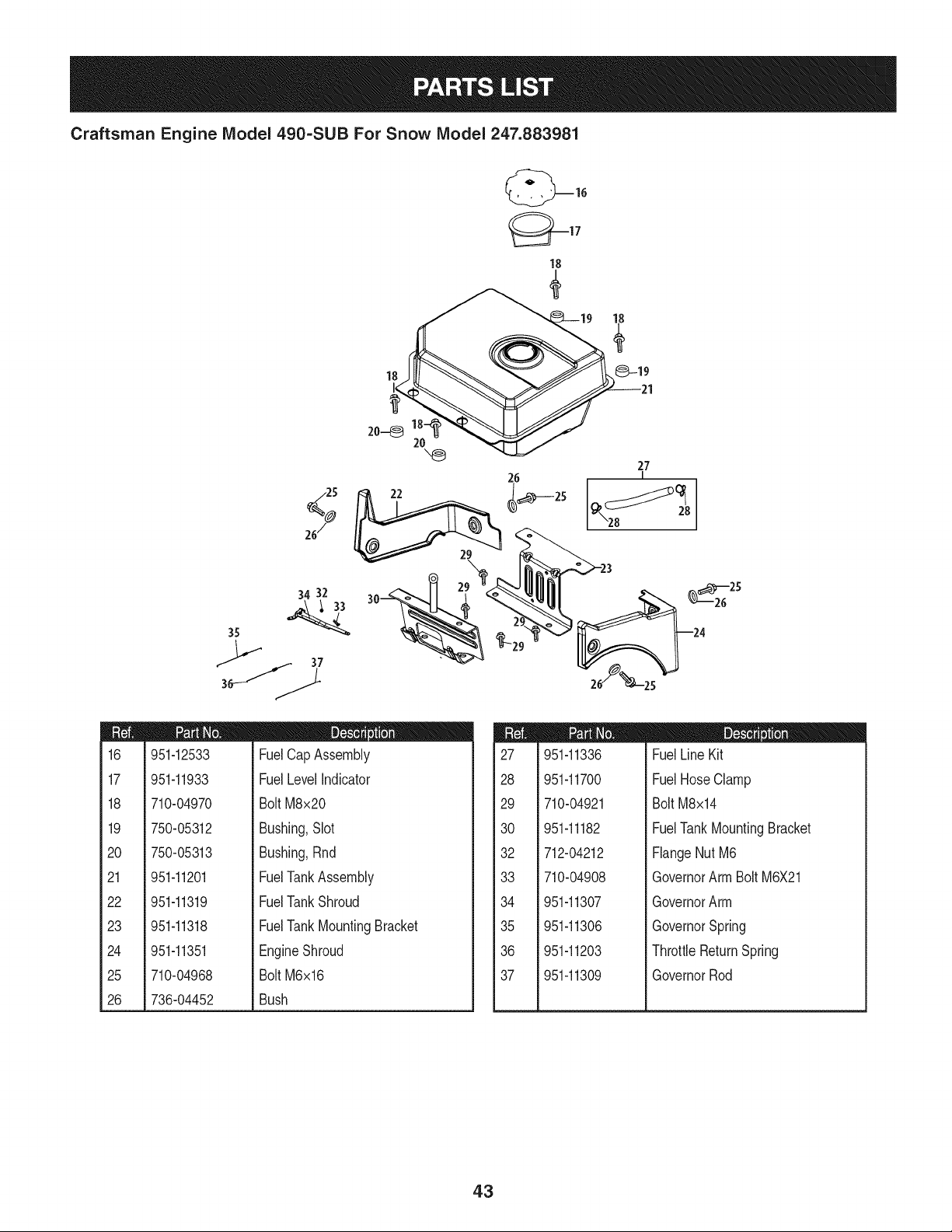
Craftsman Engine IViodel 490=SUB For Snow IViodel 247.883981
m
16
17
18
19
2O
21
22
23
24
25
26
(_17
18
"_ 27
26
I
34 32
24
951-12533
951-11933
710-04970
750-05312
750-05313
951-11201
951-11319
951-11318
951-11351
710-04968
736-04452
D = O
FuelCap Assembly
FuelLevelIndicator
BoltM8x20
Bushing,Slot
Bushing,Rnd
FuelTankAssembly
FuelTankShroud
FuelTankMountingBracket
EngineShroud
BoltM6x16
Bush
m
27
28
29
30
32
33
34
35
36
37
951-11336
951-11700
710-04921
951-11182
712-04212
710-04908
951-11307
951-11306
951-11203
951-11309
m = O O
FuelLine Kit
FuelHose Clamp
Bolt M8x14
FuelTankMountingBracket
FlangeNut M6
GovernorArm Bolt M6X21
GovernorArm
GovernorSpring
ThrottleReturnSpring
GovernorRod
43
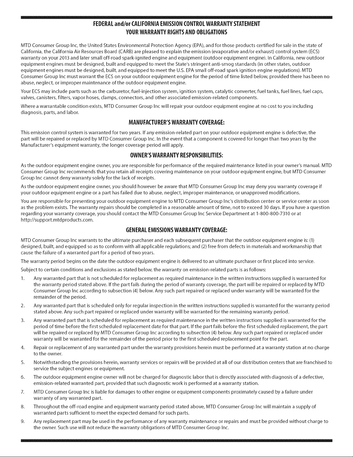
FEDERALand/or CALIFORNIAEMISSIONCONTROLWARRANTYSTATEMENT
YOURWARRANTYRIGHTSANDOBLIGATIONS
MTD Consumer Group Inc, the United States Environmental Protection Agency (EPA), and for those products certified for sale in the state of
California, the California Air Resources Board (CARB) are pleased to explain the emission (evaporative and/or exhaust) control system (ECS)
warranty on your 2013 and later small off-road spark-ignited engine and equipment (outdoor equipment engine). In California, new outdoor
equipment engines must be designed, built and equipped to meet the State's stringent anti-smog standards (in other states, outdoor
equipment engines must be designed, built, and equipped to meet the U.S. EPA small off-road spark ignition engine regulations). MTD
Consumer Group Inc must warra nt the ECSon your outdoor equipment engine for the period of time listed below, provided there has been no
abuse, neglect, or improper maintenance of the outdoor equipment engine.
Your ECS may include parts such as the carburetor, fuel-injection system, ignition system, catalytic converter, fuel tanks, fuel lines, fuel caps,
valves, canisters, filters, vapor hoses, clamps, connectors, and other associated emission-related components.
Where a warrantable condition exists, MTD Consumer Group Inc will repair your outdoor equipment engine at no cost to you including
diagnosis, parts, and labor.
MANUFACTURER'SWARRANTYCOVERAGE:
This emission control system is warranted for two years. If any emission-related part on your outdoor equipment engine is defective, the
part will be repaired or replaced by MTD Consumer Group Inc. In the event that a component is covered for longer than two years by the
Manufacturer's equipment warranty, the longer coverage period will apply.
/
OWNERSWARRANTYRESPONSIBILITIES:
As the outdoor equipment engine owner, you are responsible for performance of the required maintenance listed in your owner's manual. MTD
Consumer Group Inc recommends that you retain all receipts covering maintenance on your outdoor equipment engine, but MTD Consumer
Group Inc cannot deny warranty solely for the lack of receipts.
As the outdoor equipment engine owner, you should however be aware that MTD Consumer Group Inc may deny you warranty coverage if
your outdoor equipment engine or a part has failed due to abuse, neglect, improper maintenance, or unapproved modifications.
You are responsible for presenting your outdoor equipment engine to MTD Consumer Group Inc's distribution center or service center as soon
as the problem exists. The warranty repairs should be completed in a reasonable amount of time, not to exceed 30 days. If you have a question
regarding your warranty coverage, you should contact the MTD Consumer Group Inc Service Department at 1-800-800-7310 or at
http://su pport.mtd prod ucts.com.
GENERALEMISSIONSWARRANTYCOVERAGE:
MTD Consumer Group Inc warrants to the ultimate purchaser and each subsequent purchaser that the outdoor equipment engine is: (1)
designed, built, and equipped so as to conform with all applicable regulations; and (2) free from defects in materials and workmanship that
cause the failure of a warranted part for a period of two years.
The warranty period begins on the date the outdoor equipment engine is delivered to an ultimate purchaser or first placed into service.
Subject to certain conditions and exclusions as stated below, the warranty on emission-related parts is as follows:
1. Any warranted part that is not scheduled for replacement as required maintenance in the written instructions supplied is warranted for
the warranty period stated above. If the part fails during the period of warranty coverage, the part will be repaired or replaced by MTD
Consumer Group Inc according to subsection (4) below. Any such part repaired or replaced under warranty will be warranted for the
remainder of the period.
2. Any warranted part that is scheduled only for regular inspection in the written instructions supplied is warranted for the warranty period
stated above. Any such part repaired or replaced under warranty will be warranted for the remaining warranty period.
3. Any warranted part that is scheduled for replacement as required maintenance in the written instructions supplied is warranted for the
period of time before the first scheduled replacement date for that part. If the part fails before the first scheduled replacement, the part
will be repaired or replaced by MTD Consumer Group Inc according to subsection (4) below. Any such part repaired or replaced under
warranty will be warranted for the remainder of the period prior to the first scheduled replacement point for the part.
Repair or replacement of any warranted part under the warranty provisions herein must be performed at a warranty station at no charge
to the owner.
4.
5. Notwithstanding the provisions herein, warranty services or repairs will be provided at all of our distribution centers that are franchised to
service the subject engines or equipment.
6. The outdoor equipment engine owner will not be charged for diagnostic labor that is directly associated with diagnosis of a defective,
emission-related warranted part, provided that such diagnostic work is performed at a warranty station.
7. MTD Consumer Group Inc is liable for damages to other engine or equipment components proximately caused by a failure under
warranty of any warranted part.
8. Throughout the off-road engine and equipment warranty period stated above, MTD Consumer Group Inc will maintain a supply of
warranted parts sufficient to meet the expected demand for such parts.
9. Any replacement part may be used in the performance of any warranty maintenance or repairs and must be provided without charge to
the owner. Such use will not reduce the warranty obligations of MTD Consumer Group Inc.
10. Add-onormodifiedpartsthatarenotexemptedbytheAirResourcesBoardmaynotbeused.Theuseofanynon-exemptedadd-onor
modifiedpartsbytheultimatepurchaserwillbegroundsfordisallowingawarrantyclaims.MTDConsumerGroupIncwillnotbeliableto
warrantfailuresofwarrantedpartscausedbytheuseofanon-exemptedadd-onormodifiedpart.
WARRANTEDPARTS:
The repair or replacement of any warranted part otherwise eligible for warranty coverage may be excluded from such warranty coverage if
MTD Consumer Group Inc demonstrates that the outdoor equipment engine has been abused, neglected, or improperly maintained, and that
such abuse, neglect, or improper maintenance was the direct cause of the need for repair or replacement of the part. That notwithstanding,
any adjustment of a component that has a factory installed, and properly operating, adjustment limiting device is still eligible for warranty
coverage. Further, the coverage under this warranty extends only to parts that were present on the off-road engine and equipment purchased.
The following emission warranty parts are covered (if applicable):
1. Fuel Metering System
Cold start enrichment system (soft choke)
Carburetor and internal parts (or fuel injection system)
Fuel pump
Fuel tank
2. Air Induction System
Air cleaner
Intake manifold
3. Ignition System
Spark plug(s)
Magneto ignition system
4. Exhaust System
Catalytic converter
SAI (Reed valve)
5. Miscellaneous Items Used in Above System
Vacuum, temperature, position, time sensitive valves and switches
Connectors and assemblies
6. Evaporative Control
Fuel hose
Fuel hose clamps
Tethered fuel cap
Carbon canister
Vapor lines
050790 Rev.A
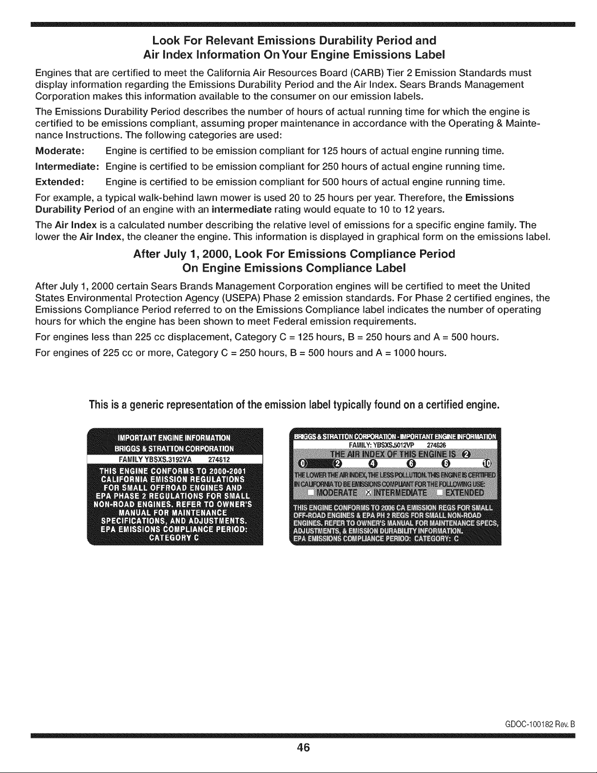
Look For Relevant Emissions Durability Period and
Air index information On Your Engine Emissions Label
Engines that are certified to meet the California Air Resources Board (CARB) Tier 2 Emission Standards must
display information regarding the Emissions Durability Period and the Air Index. Sears Brands Management
Corporation makes this information available to the consumer on our emission labels.
The Emissions Durability Period describes the number of hours of actual running time for which the engine is
certified to be emissions compliant, assuming proper maintenance in accordance with the Operating & Mainte-
nance Instructions. The following categories are used:
Moderate: Engine is certified to be emission compliant for 125 hours of actual engine running time.
Intermediate: Engine is certified to be emission compliant for 250 hours of actual engine running time.
Extended: Engine is certified to be emission compliant for 500 hours of actual engine running time.
For example, a typical walk-behind lawn mower is used 20 to 25 hours per year. Therefore, the Emissions
Durability Period of an engine with an intermediate rating would equate to 10 to 12 years.
The Air index is a calculated number describing the relative level of emissions for a specific engine family. The
lower the Air Index, the cleaner the engine. This information is displayed in graphical form on the emissions label.
After July 1,2000, Look For Emissions Compliance Period
On Engine Emissions Compliance Label
After July 1, 2000 certain Sears Brands Management Corporation engines will be certified to meet the United
States Environmental Protection Agency (USEPA) Phase 2 emission standards. For Phase 2 certified engines, the
Emissions Compliance Period referred to on the Emissions Compliance label indicates the number of operating
hours for which the engine has been shown to meet Federal emission requirements.
For engines less than 225 cc displacement, Category C = 125 hours, B = 250 hours and A = 500 hours.
For engines of 225 cc or more, Category C = 250 hours, B = 500 hours and A = 1000 hours.
This is a generic representation of the emission label typically found on a certified engine.
FAMILYYBSXS.3192VA 274812
GDOC-100182Rev.B
46
Congratulations on making a smart purchase. Your new Craftsman® product is designed and
manufactured for years of dependable operation. But like all products, it may require repair
from time to time. That's when having a Repair Protection Agreement can save you money and
aggravation.
Here's what the Repair Protection Agreement* includes:
[] Expert service by our 10,000 professional repair specialists
[] Unlimited service and no charge for parts and labor on all covered repairs
[] Product replacement up to $1500 if your covered product can't be fixed
[] Discount of 25% from regular price of service and related installed parts not covered by the
agreement; also, 25% off regular price of preventive maintenance check
[] Fast help by phone - we call it Rapid Resolution - phone support from a Sears representative.
Think of us as a "talking owner's manual."
Once you purchase the Repair Protection Agreement, a simple phone call is all that it takes for you
to schedule service. You can call anytime day or night, or schedule a service appointment online.
The Repair Protection Agreement is a risk-free purchase. If you cancel for any reason during the
product warranty period, we will provide a full refund. Or, a prorated refund anytime after the
product warranty period expires. Purchase your Repair Protection Agreement today!
Some limitations and exclusions apply. For prices and additional information in the U.S.A.
call 1=800=827=6655.
*Coverage in Canada varies on some items. For full details call Sears Canada at 1=800=361=
6665.
Sears Installation Service
For Sears professional installation of home appliances, garage door openers, water heaters, and
other major home items, in the U.S.A. or Canada call 1=800=4=MY=HOME®.
47

Your Home
For troubleshooting, product manuals and expert advice:
managernylife
www.managemylife.com
For repair - in your home - of all major brand appliances,
lawn and garden equipment, or heating and cooling systems,
no matter who made it, no matter who sold it!
For the replacement parts, accessories and
owner's manuals that you need to do-it-yourself.
For Sears professional installation of home appliances
and items like garage door openers and water heaters.
1-800-4-MY-HOME ® (1-800-469-4663)
Call anytime, day or night (U.S.A. and Canada)
www.sears.com www.sears.ca
Our Home
For repair of carry-in items like vacuums, lawn equipment,
and electronics, call anytime for the location of your nearest
Sears Parts & Repair Service Center
1-800-488-1222 (U.S.A.) 1-800-469-4663 (Canada)
www.sears.com www.sears.ca
To purchase a protection agreement on a product serviced by Sears:
1-800-827-6655 (U.S.A.) 1-800-361-6665 (Canada)
Para pedir servicio de reparaci6n
a domicilio, y para ordenar piezas:
1-888-SU-HOGAR ®
(1-888-784-6427)
www.sears.com
Au Canada pour service en frangais:
1-800-LE-FOYER Mc
(1-800-533-6937)
www.sears.ca
® Registered Trademark / TMTrademark of KCD IP, LLC in the United States, or Sears Brands, LLC in other countries
® Marca Registrada ! TMMarca de Fabrica de KCD IP, LLC en Estados Unidos, o Sears Brands, LLC in otros paises
MCMarque de commerce ! MDMarque deposee de Sears Brands, LLC


