Loading ...
Loading ...
Loading ...
NOTE:Referencesto rightorleft sideof the snowthrowerare
determinedfrombehindthe unit inthe operatingposition(standing
directlybehindthe snow thrower,facingthe handlepanel).
REMOVING FROM CRATE
1. Removescrewsfrom the bottomof thecratesecuringthesides,
andendsof the shippingcrate.
2. Lift off the topoff of the crateandsetoutof thewayof the
assemblyarea.
3. Removeanddiscardplasticbagthatcoversunit.
4. Removeany looseparts includedwith unit (e.g.,Operator's
Manual,etc.).
5. Pushdownon the lowerhandleandpullunit backout of crate.
6. Makecertainthe cratehas beencompletelyemptiedbefore
discardingit.
ASSEMBLY
1. Makecertainthe springsat the lowerend of the augeranddrive
cablesaresecurelyhookedintotheir respectiveactuator
bracketbeforepivotingthe handleupward.Referto Fig. 10.
a. Placethe shiftleverin the F6position.
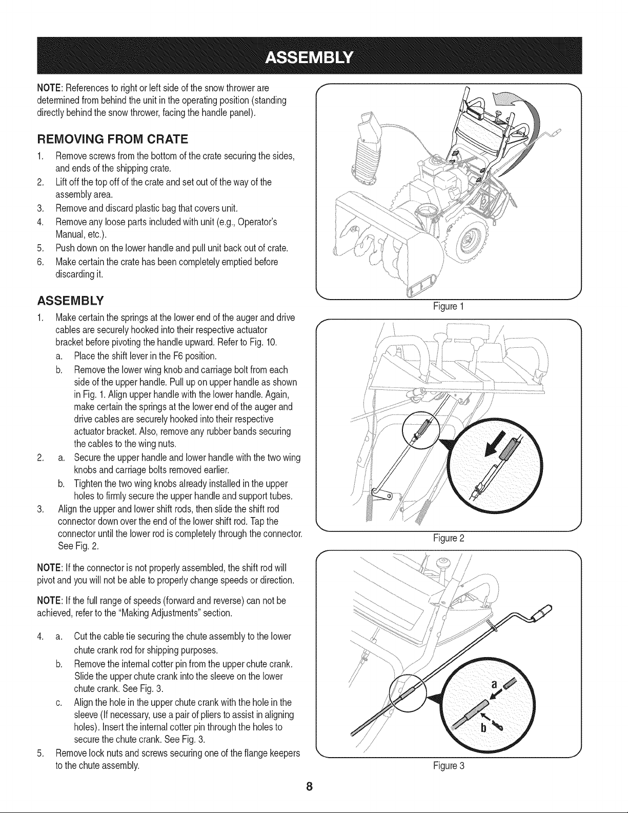
b. Removethe lowerwing knoband carriagebolt fromeach
sideof the upperhandle.Pullupon upper handleas shown
in Fig.1.Alignupperhandlewith the lowerhandle.Again,
makecertainthe springsat the lowerend of the augerand
drivecablesaresecurelyhookedintotheir respective
actuatorbracket.Also,removeany rubberbandssecuring
thecablesto the wingnuts.
2. a. Securethe upperhandleandlowerhandlewiththetwo wing
knobsandcarriageboltsremovedearlier.
b. Tightenthetwo wingknobsalreadyinstalledin the upper
holesto firmlysecurethe upperhandleand supporttubes.
3. Align the upperand lowershift rods,thenslidethe shift rod
connectordownoverthe end of the lowershift rod.Tapthe
connectoruntilthe lower rodis completelythroughtheconnector.
See Fig.2.
NOTE:If theconnectoris notproperlyassembled,the shift rodwill
pivotand youwill notbe ableto properlychangespeedsordirection.
NOTE:If thefull rangeof speeds(forwardandreverse)can not be
achieved,referto the "MakingAdjustments"section.
4. a. Cutthe cabletie securingthe chuteassemblyto the lower
chutecrankrodfor shippingpurposes.
b. Removethe internalcotterpinfromthe upperchutecrank.
Slidethe upperchute crankinto the sleeveon the lower
chutecrank.See Fig.3.
c. Alignthe holein the upperchutecrankwiththe hole in the
sleeve(if necessary,usea pairof pliersto assistinaligning
holes).Insertthe internalcotter pinthroughthe holesto
securethe chutecrank.See Fig. 3.
5. Removelock nutsand screwssecuringoneof the flangekeepers
to the chuteassembly.
Figure 1
/
f
Figure2
Figure3
8
Loading ...
Loading ...
Loading ...