Loading ...
Loading ...
Loading ...
Movetheremotechuteleveronthecontrolpanelforwardtopivotthe
upperchutedown;movetheleverrearwardtopivottheupperchute
up,
Wheel drive control
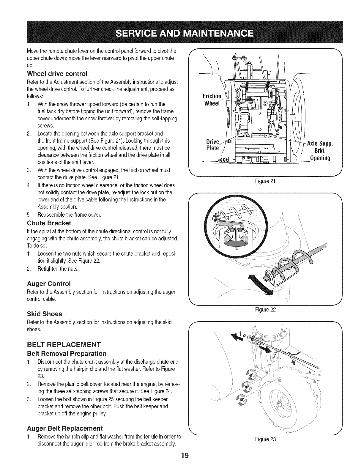
RefertotheAdjustmentsectionoftheAssemblyinstructionstoadjust
thewheeldrivecontrol,Tofurtherchecktheadjustment,proceedas
follows:
1. Withthesnowthrowertippedforward(becertaintorunthe
fueltankdrybeforetippingtheunitforward),removetheframe
coverunderneaththesnowthrowerbyremovingtheself-tapping
screws.
2. Locatetheopeningbetweentheaxlesupportbracketand
thefrontframesupport(SeeFigure21).Lookingthroughthis
opening,withthewheeldrivecontrolreleased,theremustbe
clearancebetweenthefrictionwheelandthedriveplateinall
positionsoftheshiftlever.
3. Withthewheeldrivecontrolengaged,thefrictionwheelmust
contactthedriveplate.SeeFigure21.
4. Ifthereisnofrictionwheelclearance,orthefrictionwheeldoes
notsolidlycontactthedriveplate,re-adjustthelocknutonthe
lowerendofthedrivecablefollowingtheinstructionsinthe
Assemblysection.
5. Reassembletheframecover.
Chute Bracket
Ifthespiralatthebottomofthechutedirectionalcontrolisnotfully
engagingwiththe chuteassembly,the chute bracketcan beadjusted.
Todo so:
1. Loosenthe two nuts which securethechute bracketand reposi-
tion it slightly.See Figure22.
2. Retightenthe nuts.
Auger Control
Referto the Assemblysectionfor instructionsonadjustingtheauger
controlcable.
Skid Shoes
Referto the Assemblysectionfor instructionsonadjustingthe skid
shoes.
BELT REPLACEMENT
Belt Removal Preparation
1. Disconnectthe chutecrankassemblyat the dischargechute end
by removingthe hairpinclipandthe flat washer.Referto Figure
23.
2. Removetheplasticbelt cover,locatednearthe engine,by remov-
ingthe threeself-tappingscrewsthatsecureit. SeeFigure24.
3. Loosenthe bolt shownin Figure25 securingthe belt keeper
bracketandremovetheother bolt. Pushthe belt keeperand
bracketupoff the enginepulley.
Auger Belt Replacement
1. Removethehairpinclip and flat washerfrom theferrulein orderto
disconnectthe augeridler rod from the brakebracketassembly.
f
Drive Axle Supp.
Plate Brkt.
Opening
Figure21
l
j_
Figure22
Figure23
19
Loading ...
Loading ...
Loading ...