Loading ...
Loading ...
Loading ...
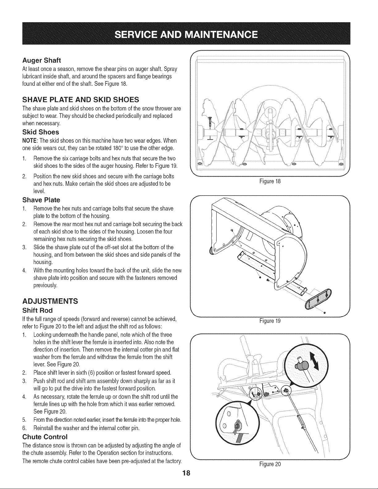
Auger Shaft
Atleastonceaseason,removetheshearpinsonaugershaft.Spray
lubricantinsideshaft,andaroundthespacersandflangebearings
foundateitherendoftheshaft.SeeFigure18.
SHAVE PLATE AND SKID SHOES
The shaveplateand skidshoesonthe bottomof the snowthrowerare
subjectto wear.They shouldbe checkedperiodicallyand replaced
whennecessary.
Skid Shoes
NOTE:Theskidshoeson thismachinehavetwowearedges.When
onesidewearsout,theycan be rotated1800to usethe otheredge.
1. Removethe sixcarriageboltsandhexnutsthatsecurethe two
skidshoesto the sidesof theauger housing.Referto Figure19.
2. Positionthe new skidshoesandsecurewiththe carriagebolts
andhexnuts. Makecertainthe skidshoesareadjustedto be
level.
Shave Plate
1. Removethe hexnutsandcarriageboltsthatsecurethe shave
plateto the bottomof the housing.
2. Removethe rearmost hexnut andcarriagebolt securingthe back
of eachskid shoeto the sidesof the housing.Loosenthefour
remaininghexnutssecuringthe skid shoes.
3. Slidethe shaveplateout of the off-setslotatthe bottomof the
housing,andfrombetweenthe skid shoesand side panelsof the
housing.
4. Withthe mountingholestowardthe backof the unit,slidethe new
shaveplateinto positionand securewiththe fastenersremoved
previously.
ADJUSTMENTS
Shift Rod
Ifthe full rangeof speeds(forwardandreverse)cannotbe achieved,
referto Figure20 to the left and adjust the shift rodas follows:
1. Lookingunderneaththe handlepanel,notewhichof thethree
holesinthe shiftleverthe ferruleis insertedinto.Also notethe
directionof insertion.Thenremovethe internalcotter pin and flat
washerfromthe ferruleand withdrawtheferrulefrom the shift
lever.SeeFigure20.
2. Placeshift leverin sixth (6) positionor fastestforwardspeed.
3. Pushshift rodandshiftarm assemblydownsharplyas far as it
willgo to put the driveintothe fastestforwardposition.
4. As necessary,rotatethe ferruleupor downthe shiftrod untilthe
ferrulelinesupwiththe hole from whichit wasearlier removed.
SeeFigure20.
5. Fromthedirectionnotedearlier,inserttheferruleintothe properhole.
6. Reinstallthe washerandthe internalcotter pin.
Chute Control
Thedistancesnowis throwncan beadjustedby adjustingthe angleof
thechuteassembly.Referto the Operationsectionfor instructions.
The remotechutecontrol cableshavebeen preladjustedat the factory.
18
f
f
/ /7 "'! ......_, .....
.............. _':'f!'t, .......... }_\_. _,
i _ \ .....77',!.1< ' L _k;,..... +El'\t;......
k, -Jr 7 r'W'i / '
, , _ ' ...... 7
....................,'r......................................\ i ........ +>, F .............................
J
Figure18
Figure19
t,
' ii /
Figure20
Loading ...
Loading ...
Loading ...