Operator's Manual
P R 0 F E S S I 0 N A L
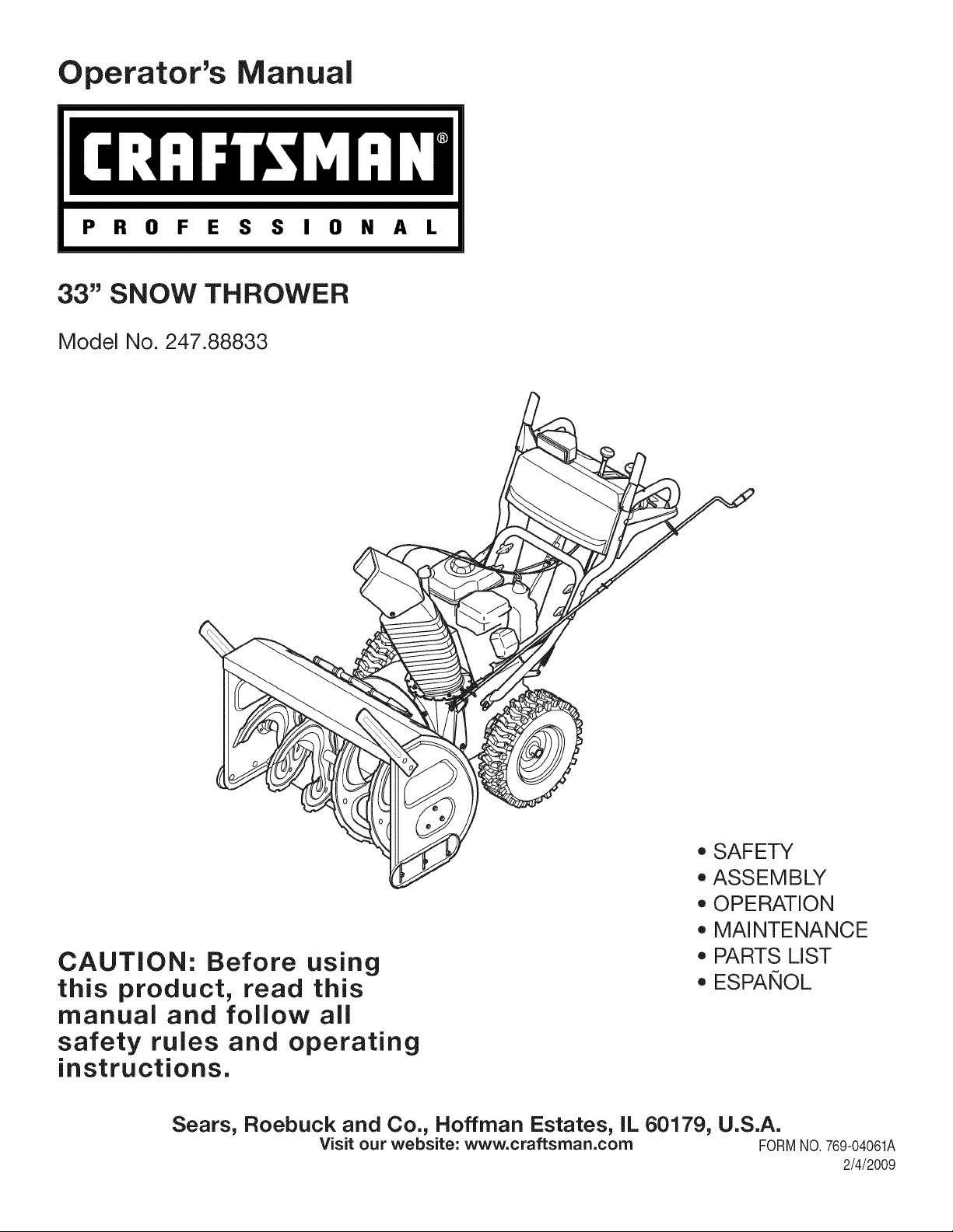
33" SNOW THROWER
Model No. 247.88833
CAUTION: Before using
this product, read this
manual and follow all
safety rules and operating
instructions.
, SAFETY
, ASSEMBLY
, OPERATION
, MAINTENANCE
, PARTS LIST
o ESPANOL
Sears, Roebuck and Co., Hoffman Estates, IL 60179, U.S.A.
Visit our website: www.craftsman.com FORMNO.769-04061A
2/4/2009
WarrantyStatement..................................Page2
SafeOperationPractices..........................Pages3-6
SafetyLabels............................................Page7
Assembly..................................................Pages8-11
Operation..................................................Pages12-15
ServiceandMaintenance.........................Pages16-23
Off-SeasonStorage..................................Page24
Troubleshooting........................................Page25
PartsList...................................................Page26-41
RepairProtectionAgreement...................Page46
Espa_ol.....................................................Page47
ServiceNumbers......................................BackCover
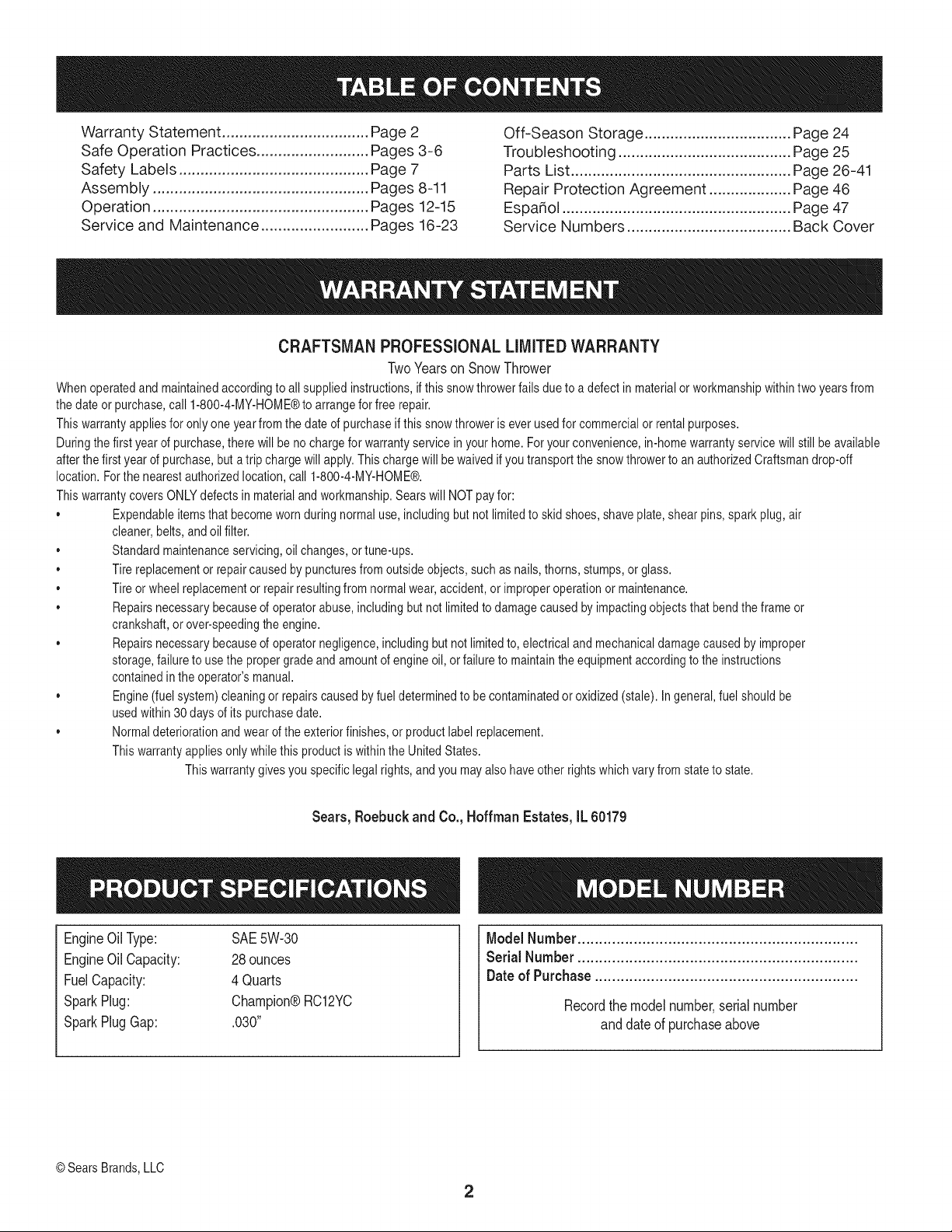
CRAFTSMAN PROFESSIONAL LiMiTED WARRANTY
Two Years on Snow Thrower
Whenoperatedand maintainedaccordingto all suppliedinstructions,if this snowthrowerfailsdue to a defect in materialor workmanshipwithintwo yearsfrom
thedate or purchase,call 1-800-4-MY-HOME®to arrangefor free repair.
Thiswarrantyappliesfor onlyone yearfrom the dateof purchaseif this snowthroweris everusedfor commercialorrental purposes.
Duringthefirst yearof purchase,therewill beno chargefor warrantyservicein your home.Foryour convenience,in-homewarrantyservicewill still be available
after thefirst year of purchase,but atrip chargewill apply.This chargewillbe waivedif you transportthe snowthrowerto an authorizedCraftsmandrop-off
location.For the nearestauthorizedlocation,call 1-800-4-MY-HOME®.
ThiswarrantycoversONLYdefects in materialand workmanship.Sears willNOTpayfor:
• Expendableitemsthat becomewornduringnormaluse,includingbut notlimitedto skidshoes,shaveplate,shearpins,sparkplug, air
cleaner,belts,and oil filter.
• Standardmaintenanceservicing,oil changes,ortune-ups.
• Tire replacementor repaircausedby puncturesfromoutsideobjects,such as nails, thorns,stumps,or glass.
• Tire or wheel replacementor repairresultingfrom normalwear,accident,or improperoperationor maintenance.
• Repairsnecessarybecauseof operatorabuse,includingbut notlimitedto damagecausedby impactingobjectsthat bendthe frameor
crankshaft,orover-speedingthe engine.
• Repairsnecessarybecauseof operatornegligence,includingbut notlimitedto, electricaland mechanicaldamagecausedby improper
storage,failureto usethe propergradeandamountof engineoil, orfailure to maintainthe equipmentaccordingto the instructions
containedinthe operator'smanual.
• Engine(fuel system)cleaningor repairscausedby fuel determinedto be contaminatedor oxidized(stale). In general,fuel should be
usedwithin30 daysof itspurchasedate.
• Normaldeteriorationandwearof the exteriorfinishes,or productlabelreplacement.
Thiswarrantyappliesonly while this productis withinthe UnitedStates.
Thiswarrantygivesyou specific legal rights,and you mayalsohaveother rightswhichvaryfromstateto state.
Sears, Roebuck and Co., Hoffman Estates, IL 60179
EngineOilType: SAE5W-30
EngineOilCapacity: 28ounces
FuelCapacity: 4 Quarts
SparkPlug: Champion®RC12YC
SparkPlugGap: .030"
Model Number.................................................................
Serial Number .................................................................
Dateof Purchase.............................................................
Recordthe modelnumber,serialnumber
anddateof purchaseabove
© Sears Brands,LLC
2
Thissymbolpointsout importantsafetyinstructionswhich,if not
followed,couldendangerthepersonalsafetyand/orpropertyof
yourselfandothers. Readand followall instructionsin thismanual
beforeattemptingto operatethis machine.Failureto complywith
theseinstructionsmay resultin personalinjury.Whenyou seethis
symbol,HEEDITSWARNING!
CALIFORNIA PROPOSITION 65
EngineExhaust,someof itsconstituents,and certainvehicle
componentscontainoremitchemicalsknownto Stateof California
to cause cancerand birthdefects or otherreproductiveharm,
Thismachinewasbuiltto be operatedaccordingto the safeopera-
tion practicesin this manual.As with anytype of powerequipment,
carelessnessor error on the partof the operatorcan resultin serious
injury.Thismachineis capableof amputatingfingers,hands,toes
andfeetandthrowingdebris.Failureto observethe followingsafety
instructionscouldresultin seriousinjuryor death.
Your Responsibility--Restrict the useof this powermachineto
personswho read,understandand follow thewarningsand instruc-
tionsin this manualand on the machine,
SAVE THESE INSTRUCTIONS!
TRAiNiNG
• Read,understand,andfollowall instructionson the machineand
in themanual(s)beforeattemptingto assembleandoperate.
Failureto do socan resultinseriousinjuryto the operatorand/
orbystanders.Keepthismanualin a safeplaceforfutureand
regularreferenceandfor orderingreplacementparts. Forques-
tionscall,1-800-659-5917.
• Befamiliarwithall controlsand their properoperation.Knowhow
to stop the machineanddisengagethemquickly.
• Neverallowchildrenunder14yearsof age to operatethis
machine.Children14andover shouldreadand understandthe
instructionsand safe operationpracticesin thismanualandon
the machineand be trainedandsupervisedby an adult.
• Neverallowadultsto operatethis machinewithoutproper
instruction.
• Thrownobjectscan causeseriouspersonalinjury. Planyour
snow-throwingpatternto avoiddischargeof materialtoward
roads,bystandersandthe like.
• Keepbystanders,petsandchildrenat least75 feet from the
machinewhile itisin operation.Stopmachineifanyoneenters
the area.
• Exercisecautionto avoidslippingor falling,especiallywhen
operatinginreverse.
PREPARATION
Thoroughlyinspecttheareawherethe equipmentis to be used.
Removeall doormats,newspapers,sleds,boards,wiresandother
foreignobjects,whichcouldbe trippedoverorthrownby the auger/
impeller.
Alwayswear safetyglassesor eyeshieldsduringoperationand
while performingan adjustmentor repairto protectyoureyes.
Thrownobjectswhichricochetcancauseseriousinjuryto the
eyes.
Donot operatewithoutwearingadequatewinteroutergarments.
Donot wearjewelry,long scarvesor otherlooseclothing,which
could becomeentangledin movingparts.Wearfootwearwhich
will improvefooting on slipperysurfaces.
Usea groundedthree-wireextensioncordand receptaclefor all
machineswith electricstartengines.
Disengageall controlleversbeforestartingthe engine.
Adjustcollectorhousingheightto cleargravelor crushedrock
surfaces.
Neverattemptto make anyadjustmentswhileengineis running,
exceptwherespecificallyrecommendedinthe operator'smanual.
Letengineandmachineadjustto outdoortemperaturebefore
startingto clearsnow.
3
Safe Handling of Gasoline
Toavoidpersonalinjuryor propertydamageuseextremecare in
handlinggasoline.Gasolineis extremelyflammableandthe vaporsare
explosive.Seriouspersonalinjurycan occurwhengasolineis spilled
onyourselfor yourclotheswhichcan ignite.Washyour skin and
changeclothesimmediately.
• Useonly anapprovedgasolinecontainer.
• Extinguishall cigarettes,cigars,pipesandother sources
of ignition.
• Neverfuelmachineindoors.
• Neverremovegas capor add fuel whilethe engineis hot
or running.
• Allowengine to coolat leasttwo minutesbeforerefueling.
• Neveroverfill fueltank. Filltank to no morethan1/2inch
belowbottomof filler neckto providespacefor fuel
expansion.
• Replacegasolinecap and tightensecurely.
• If gasolineis spilled,wipeit offthe engineand equipment.
Movemachineto anotherarea.Wait5 minutesbefore
startingthe engine.
• Neverstorethe machineor fuel containerinsidewhere
thereis an open flame,sparkor pilotlight (e.g.furnace,
waterheater,spaceheater,clothesdryer etc.).
• Allowmachineto cool at least5 minutesbeforestoring.
• Neverfill containersinsidea vehicleor ona truckor trailer
bedwitha plasticliner.Alwaysplacecontainerson the
groundawayfromyourvehiclebeforefilling.
• If possible,removegas-poweredequipmentfromthetruck
ortrailerand refuelit on the ground.If this is not possible,
then refuelsuch equipmenton a trailerwitha portable
container,ratherthan fromagasolinedispensernozzle.
• Keepthe nozzleincontactwiththe rimof the fueltankor
containeropeningat all timesuntil fuelingis complete.Do
notuse a nozzlelock-opendevice.
OPERATION
• Do not puthandsorfeetnear rotatingparts,in the auger/impeller
housingor chuteassembly.Contactwiththe rotatingpartscan
amputatehandsandfeet.
• Theauger/impellercontrolleveris a safetydevice.Neverbypass
itsoperation.Doingso makesthe machineunsafeandmaycause
personalinjury.
• Thecontrolleversmustoperateeasilyin bothdirectionsand
automaticallyreturnto the disengagedpositionwhenreleased.
• Neveroperatewith a missingor damagedchuteassembly.Keep
all safetydevicesin placeand working.
• Neverrunanengineindoorsor in a poorlyventilatedarea. Engine
exhaustcontainscarbonmonoxide,an odorlessand deadlygas.
• Do notoperatemachinewhileunderthe influenceof alcoholor
drugs.
• Mufflerand enginebecomehotandcan causea burn.Do not
touch.Keepchildrenaway.
• Exerciseextremecautionwhenoperatingon or crossinggravel
surfaces.Stayalertfor hidden hazardsor traffic.
• Exercisecautionwhenchangingdirectionandwhileoperatingon
slopes.
• Planyoursnow-throwingpatternto avoiddischargetowards
windows,walls,carsetc. Thus,avoidingpossibleproperty
damageor personalinjurycausedby a ricochet.
• Neverdirect dischargeat children,bystandersand petsor allow
anyoneinfrontof the machine.
• Donot overloadmachinecapacityby attemptingto clearsnowat
too fastof a rate.
• Neveroperatethis machinewithoutgoodvisibilityorlight.Always
be sureof yourfootingand keepa firm hold on the handles.Walk,
neverrun.
• Disengagepowerto theauger/impellerwhentransportingor not
in use.
• Neveroperatemachineat high transportspeedson slippery
surfaces.Lookdownand behindand usecare whenbackingup.
• If the machineshouldstart to vibrateabnormally,stopthe engine,
disconnectthe spark plugwire andgroundit againstthe engine.
Inspectthoroughlyfor damage.Repairanydamagebefore
startingandoperating.
• Disengageall controlleversandstopenginebeforeyouleave
the operatingposition(behindthe handles).Waituntilthe auger/
impellercomesto a completestopbeforeuncloggingthechute
assembly,makingany adjustments,or inspections.
• Neverput yourhandinthe dischargeor collectoropenings.Do
not unclogchuteassemblywhileengineis running.Shutoff
engineand remainbehindhandlesuntilall movingparts have
stoppedbeforeunclogging.
• Useonly attachmentsandaccessoriesapprovedby the manufac-
turer (e.g.wheelweights,tire chains,cabsetc.).
• Whenstartingengine,pull cord slowlyuntilresistanceis felt, then
pull rapidly.Rapidretractionof startercord(kickback)will pull
handandarmtowardenginefasterthan youcan let go. Broken
bones,fractures,bruisesor sprainscould result.
• If situationsoccur whichare notcoveredinthis manual,use care
andgoodjudgment.ContactCustomerSupportfor assistance
andthe nameof your nearestservicingdealer.
CLEARING A CLOGGED DISCHARGE CHUTE
Handcontactwiththe rotatingimpellerinsidethe dischargechute
is the mostcommoncauseof injuryassociatedwithsnowthrowers.
Neveruse yourhand to cleanout thedischargechute.
Toclear thechute:
1. SHUTTHEENGINEOFF!
2. Wait 10secondsto be surethe impellerbladeshavestopped
rotating.
3. Alwaysusea clean-outtool,not yourhands.
4
MAINTENANCE & STORAGE
• Nevertamperwithsafetydevices.Checktheirproperoperation
regularly.Referto the maintenanceandadjustmentsectionsof
thismanual.
• Beforecleaning,repairing,or inspectingmachinedisengageall
controlleversandstopthe engine.Wait untilthe auger/impeller
cometo a completestop.Disconnectthe sparkplugwireand
groundagainsttheengineto preventunintendedstarting.
Checkboltsand screwsfor propertightnessat frequentintervals
to keepthe machineinsafeworkingcondition.Also, visually
inspectmachinefor anydamage.
Do notchangetheenginegovernorsettingor over-speedthe
engine.Thegovernorcontrolsthe maximumsafeoperatingspeed
of the engine.
Snowthrowershaveplatesand skidshoesaresubjectto wear
anddamage.Foryoursafetyprotection,frequentlycheckall
componentsand replacewith originalequipmentmanufacturer's
(OEM)partsonly."Useof partswhichdo not meetthe original
equipmentspecificationsmayleadto improperperformanceand
compromisesafety!"
Checkcontrolleversperiodicallyto verifythey engageand disen-
gageproperlyandadjust,if necessary.Referto the adjustment
sectioninthisoperator'smanualfor instructions.
Maintainor replacesafetyandinstructionlabels,as necessary.
• Observeproperdisposallawsand regulationsfor gas, oil,etc. to
protectthe environment.
Priorto storing,runmachinea few minutestoclear snowfrom
machineand preventfreezeup of auger/impeller.
Neverstorethe machineor fuel containerinsidewherethereisan
openflame,sparkorpilot lightsuch as a waterheater,furnace,
clothesdryer etc.
Alwaysreferto the operator'smanualfor properinstructionson
off-seasonstorage.
Checkfuelline,tank, cap,andfittings frequentlyfor cracksor
leaks.Replaceif necessary.
Do notcrank enginewith spark plug removed.
Accordingto the ConsumerProductsSafetyCommission(CPSC)
andthe U.S.EnvironmentalProtectionAgency(EPA),this product
hasan AverageUsefulLifeof seven(7) years,or 60 hoursof
operation.At the endof theAverageUsefulLifehavethe machine
inspectedannuallybyan authorizedservicedealer to ensurethat
allmechanicalandsafetysystemsareworkingproperlyand not
wornexcessively.Failureto do so can resultinaccidents,injuries
ordeath.
DO NOT MODIFY ENGINE
Toavoidseriousinjuryor death,do not modifyengineinany way.
Tamperingwiththe governorsettingcanlead to a runawayengineand
causeit to operateat unsafespeeds.Nevertamperwithfactorysetting
of engine governor.
NOTICE REGARDING EMiSSiONS
Engineswhich are certifiedtocomplywith Californiaand federal
EPAemissionregulationsfor SORE(SmallOff RoadEquipment)are
certifiedto operateon regularunleadedgasoline,and mayinclude
the followingemissioncontrol systems:EngineModification(EM),
OxidizingCatalyst(OC),SecondaryAirInjection(SAI)and ThreeWay
Catalyst(TWO)if so equipped.
SPARK ARRESTOR
Thismachineisequippedwithaninternalcombustionengineand
shouldnotbe usedonor nearany unimprovedforest-covered,
brush-coveredorgrass-coveredland unlessthe engine'sexhaust
systemisequippedwitha sparkarrestermeetingapplicablelocalor
statelaws(if any)
Ifa sparkattesteris used,it shouldbe maintainedin effectiveworking
orderby theoperator.Inthe Stateof Californiathe aboveis required
bylaw (Section4442 of the CaliforniaPublicResourcesCode). Other
statesmayhavesimilarlaws. Federallawsapplyon federallands.
A sparkarresterfor the muffleris availablethroughyournearestSears
PartsandRepairServiceCenter.
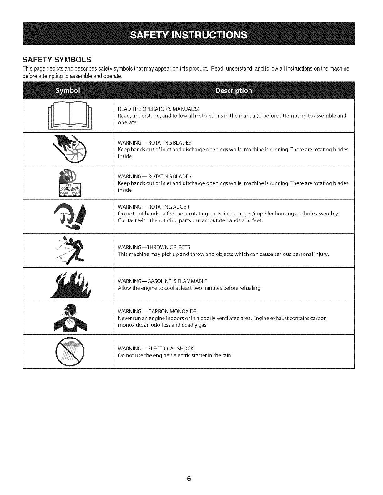
SAFETY SYMBOLS
Thispagedepictsanddescribessafetysymbolsthatmayappearonthisproduct. Read,understand,and followall instructionson the machine
beforeattemptingto assembleand operate.
i
i
READ THE OPERATOR'S MANUAL(S)
Read, understand, and follow all instructions in the manual(s) before attempting to assemble and
operate
WARNING-- ROTATING BLADES
Keep hands out of inlet and discharge openings while machine is running. There are rotating blades
inside
WARNING-- ROTATING BLADES
Keep hands out of inlet and discharge openings while machine is running. There are rotating blades
inside
WARNING-- ROTATING AUGER
Do not put hands or feet near rotating parts, in the auger/impeller housing or chute assembly.
Contact with the rotating parts can amputate hands and feet.
WARNING--THROWN OBJECTS
This machine may pick up and throw and objects which can cause serious personal injury.
WARNING--GASOLINE IS FLAMMABLE
Allow the engine to cool at least two minutes before refueling.
WARNING-- CARBON MONOXIDE
Never run an engine indoors or in a poorly ventilated area. Engine exhaust contains carbon
monoxide, an odorless and deadly gas.
WARNING-- ELECTRICAL SHOCK
Do not use the engine's electric starter in the rain
6
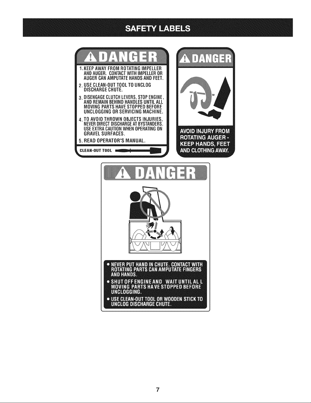
1.KEEPAWAYFROMROTATINGiMPELLER
ANDAUGER,CONTACTWiTHiMPELLEROR
AUGERCANAMPUTATEHANDSANDFEET.
2. USECLEAN-OUTTOOLTOUNCLOG
DISCHARGECHUTE.
3.DISENGAGECLUTCHLEVERS,STOPENGINE,
AND REMAINBEHINDHANDLESUNTILALL
MOVING PARTSHAVE STOPPEDBEFORE
UNCLOGGING OR SERViCiNGMACHINE.
TO AVOIDTHROWN OBJECTSiNJURiES,
NEVERDIRECTDISCHARGEATBYSTANDERS.
USEEXTRACAUTIONWHEN OPERATINGON
GRAVEL SURFACES.
5.BEAD OPERATOR'S MANUAL.
CLEAN-OUT TOOL
7
NOTE:Referencesto rightorleft sideof the snowthrowerare
determinedfrombehindthe unit inthe operatingposition(standing
directlybehindthe snow thrower,facingthe handlepanel).
REMOVING FROM CRATE
1. Removescrewsfrom the bottomof thecratesecuringthesides,
andendsof the shippingcrate.
2. Lift off the topoff of the crateandsetoutof thewayof the
assemblyarea.
3. Removeanddiscardplasticbagthatcoversunit.
4. Removeany looseparts includedwith unit (e.g.,Operator's
Manual,etc.).
5. Pushdownon the lowerhandleandpullunit backout of crate.
6. Makecertainthe cratehas beencompletelyemptiedbefore
discardingit.
ASSEMBLY
1. Makecertainthe springsat the lowerend of the augeranddrive
cablesaresecurelyhookedintotheir respectiveactuator
bracketbeforepivotingthe handleupward.Referto Fig. 10.
a. Placethe shiftleverin the F6position.
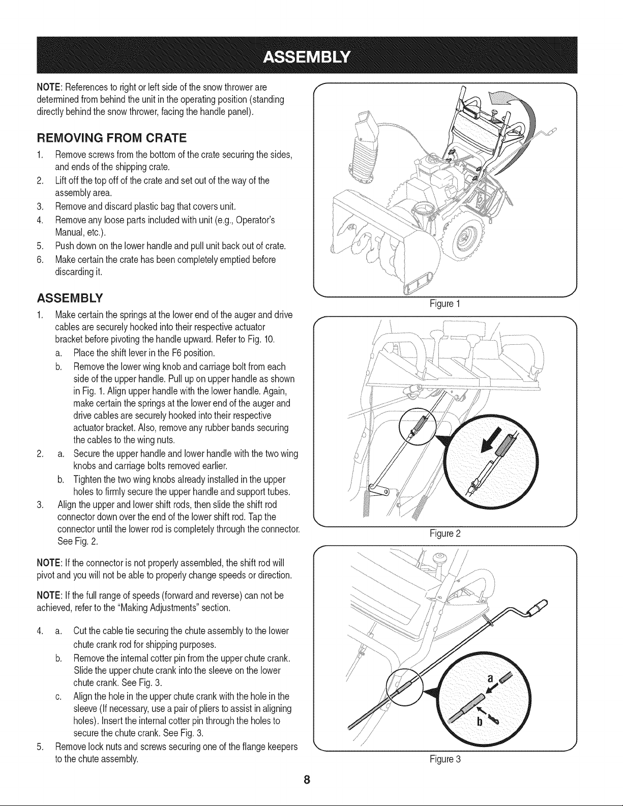
b. Removethe lowerwing knoband carriagebolt fromeach
sideof the upperhandle.Pullupon upper handleas shown
in Fig.1.Alignupperhandlewith the lowerhandle.Again,
makecertainthe springsat the lowerend of the augerand
drivecablesaresecurelyhookedintotheir respective
actuatorbracket.Also,removeany rubberbandssecuring
thecablesto the wingnuts.
2. a. Securethe upperhandleandlowerhandlewiththetwo wing
knobsandcarriageboltsremovedearlier.
b. Tightenthetwo wingknobsalreadyinstalledin the upper
holesto firmlysecurethe upperhandleand supporttubes.
3. Align the upperand lowershift rods,thenslidethe shift rod
connectordownoverthe end of the lowershift rod.Tapthe
connectoruntilthe lower rodis completelythroughtheconnector.
See Fig.2.
NOTE:If theconnectoris notproperlyassembled,the shift rodwill
pivotand youwill notbe ableto properlychangespeedsordirection.
NOTE:If thefull rangeof speeds(forwardandreverse)can not be
achieved,referto the "MakingAdjustments"section.
4. a. Cutthe cabletie securingthe chuteassemblyto the lower
chutecrankrodfor shippingpurposes.
b. Removethe internalcotterpinfromthe upperchutecrank.
Slidethe upperchute crankinto the sleeveon the lower
chutecrank.See Fig.3.
c. Alignthe holein the upperchutecrankwiththe hole in the
sleeve(if necessary,usea pairof pliersto assistinaligning
holes).Insertthe internalcotter pinthroughthe holesto
securethe chutecrank.See Fig. 3.
5. Removelock nutsand screwssecuringoneof the flangekeepers
to the chuteassembly.
Figure 1
/
f
Figure2
Figure3
8
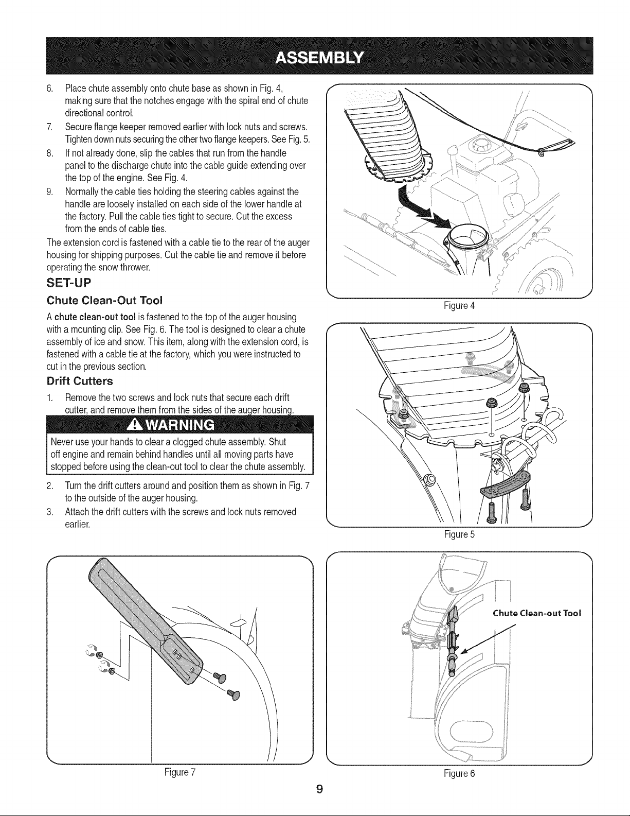
6. Placechuteassemblyonto chutebaseas shown in Fig. 4,
makingsurethatthe notchesengagewith the spiralendof chute
directionalcontrol.
7. Secureflangekeeperremovedearlierwith lock nuts and screws.
Tightendownnutssecuringtheothertwo flangekeepers.SeeFig.5.
8. If notalreadydone,slipthe cablesthat run fromthe handle
panelto the dischargechuteintothe cableguide extendingover
the topof the engine.See Fig.4.
9. Normallythecable tiesholdingthe steeringcablesagainstthe
handlearelooselyinstalledoneach sideof the lowerhandleat
the factory.Pullthe cableties tight to secure.Cutthe excess
fromtheendsof cableties.
Theextensioncord is fastenedwitha cabletie to the rearof the auger
housingfor shippingpurposes.Cut thecabletie and removeit before
operatingthe snowthrower.
SET-UP
Chute Clean=Out Tool
A chuteclean-outtool is fastenedto the top of theaugerhousing
witha mountingclip. See Fig. 6. Thetool is designedto clear a chute
assemblyof ice andsnow.Thisitem,along with the extensioncord,is
fastenedwithacable tie at the factory,whichyou wereinstructedto
cutin the previoussection.
Drift Cutters
1. Removethetwo screwsand locknutsthat secureeach drift
Neveruseyour handstoclear a cloggedchute assembly.Shut
offengineandremainbehindhandlesuntilall movingparts have
stoppedbeforeusingthe clean-outtoolto clearthe chute assembly.
2. Turnthe driftcuttersaroundandpositionthemas shownin Fig.7
to the outsideof the augerhousing.
3. Attachthedrift cutterswith the screwsand lock nuts removed
earlier.
?
Figure4
Figure5
J
J
F-
f
Chute Clean=out Tool
Figure7
9
Figure6
J
Tire Pressure f
Beforeoperating,checktire pressure.Referto the tire sidewallfor
exacttire manufacturer'srecommendedor maximumpsi.
NOTE:Ifthe tire pressureis not equal inboth tires,the unitmay not
travelina straightpathandthe shaveplatemaywear unevenly.
ADJUSTMENTS
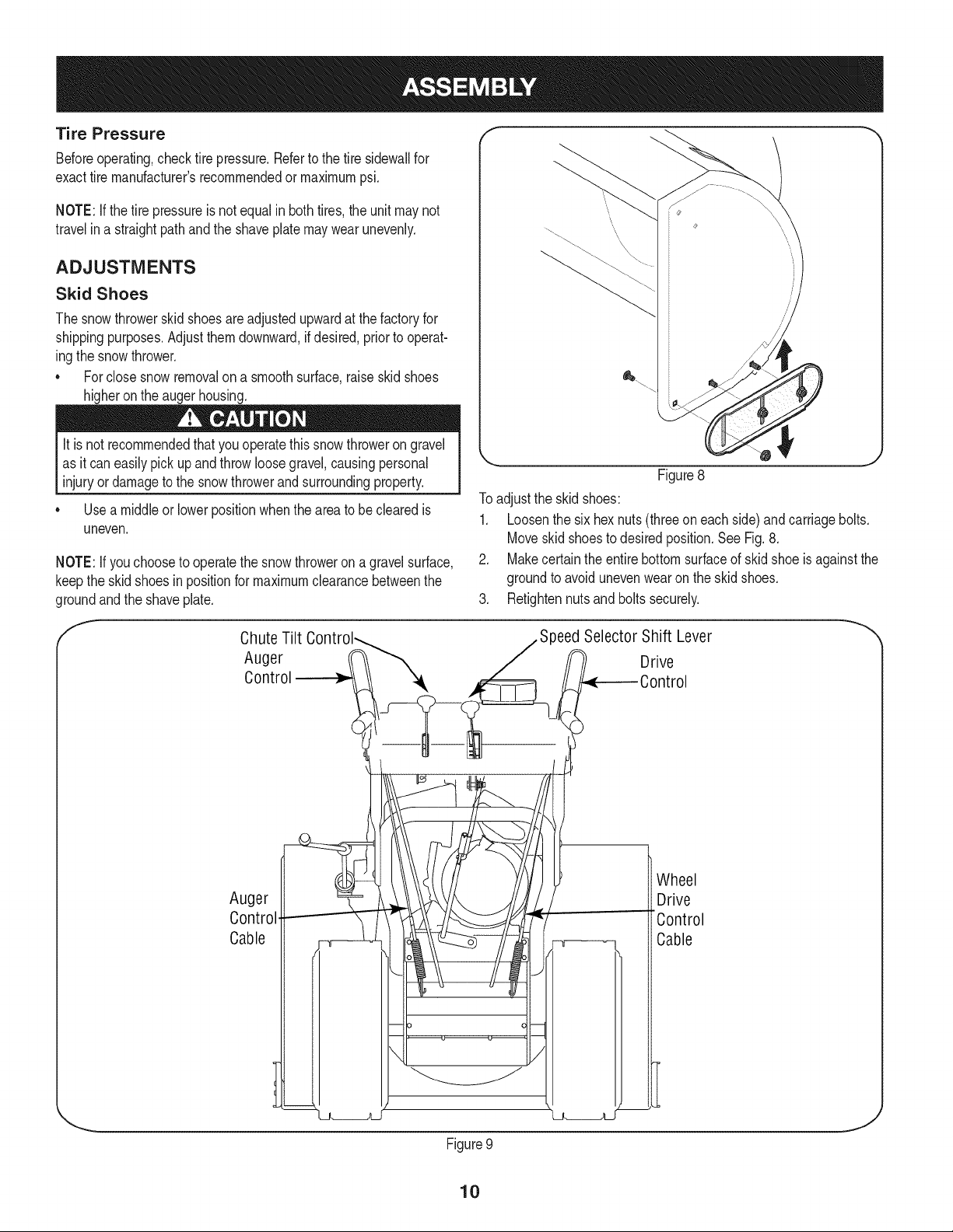
Skid Shoes
The snowthrowerskid shoesare adjustedupwardat the factoryfor
shippingpurposes.Adjustthem downward,ifdesired,priorto operat-
ingthe snowthrower.
• Forclose snow removalon a smoothsurface,raiseskid shoes
higheronthe augerhousing.
It is not recommendedthatyouoperatethissnowthrowerongravel
as itcan easilypick up and throwloosegravel,causingpersonal
injuryor damageto the snowthrowerandsurroundingproperty.
Usea middleor lowerpositionwhenthe areato beclearedis
uneven.
NOTE:Ifyouchooseto operatethe snowthrowerona gravelsurface,
keepthe skid shoes in positionfor maximumclearancebetweenthe
groundandthe shaveplate.
f
Chute Tilt
Auger
Figure8
Toadjustthe skid shoes:
1. Loosenthe sixhexnuts(threeon eachside)and carriagebolts.
Moveskidshoesto desiredposition.See Fig.8.
2. Makecertainthe entirebottomsurfaceof skid shoe isagainstthe
groundto avoidunevenwearon the skid shoes.
3. Retightennutsand boltssecurely.
)eed Selector Shift Lever _'
Drive
Auger
Control
Cable
Wheel
Drive
"Control
Cable
Figure9
J
10
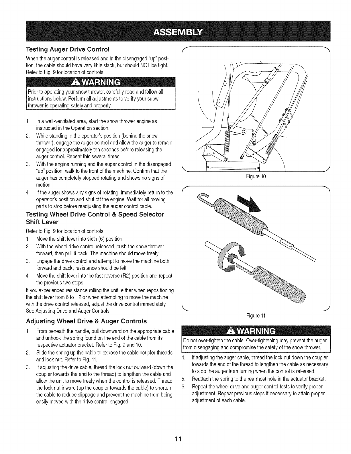
Testing Auger Drive Control
Whentheaugercontrolis releasedandin the disengaged"up"posi-
tion,the cableshouldhavevery little slack, but shouldNOTbetight.
Referto Fig.9 for locationof controls.
Priorto operatingyoursnow thrower,carefullyreadandfollowall
instructionsbelow.Performall adjustmentstoverify yoursnow
throwerisoperatingsafelyand properly.
1. In a well-ventilatedarea,start the snowthrowerengineas
instructedin the Operationsection.
2. Whilestandingin the operator'sposition(behindthe snow
thrower),engagethe augercontrolandallowtheaugerto remain
engagedfor approximatelyten secondsbeforereleasingthe
augercontrol.Repeatthis severaltimes.
3. With theengine runningand the augercontrolinthe disengaged
"up"position,walk to the frontof the machine.Confirmthatthe
augerhas completelystoppedrotatingand showsno signs of
motion.
4. If theaugershowsany signsof rotating,immediatelyreturnto the
operator'spositionand shutoff the engine.Wait for allmoving
partsto stop beforereadjustingtheauger controlcable.
Testing Wheel Drive Control & Speed Selector
Shift Lever
Referto Fig.9 for locationof controls.
1. Movethe shift leverintosixth (6) position.
2. With thewheeldrivecontrol released,pushthe snowthrower
forward,then pull it back.The machineshouldmovefreely.
3. Engagethe drivecontrolandattemptto movethe machineboth
forwardandback,resistanceshouldbefelt.
4. Movethe shift leverintothe fast reverse(R2) positionand repeat
the previoustwo steps.
If youexperiencedresistancerollingthe unit,either whenrepositioning
the shift leverfrom6 to R2 orwhenattemptingto movethe machine
withthe drivecontrolreleased,adjustthe drivecontrolimmediately.
SeeAdjustingDriveandAugerControls.
Adjusting Wheel Drive & Auger Controls
1. Frombeneaththe handle,pull downwardon theappropriatecable
andunhookthe springfoundon the endof the cablefromits
respectiveactuatorbracket.Referto Fig. 9 and10.
2. Slide thespringup thecableto exposethe cablecouplerthreads
andlocknut. Referto Fig. 11.
3. If adjustingthe drivecable,threadthe locknutoutward(downthe
couplertowardsthe end fo the thread)to lengthenthecable and
allowthe unitto movefreelywhenthe controlis released.Thread
the lock nut inward(upthe couplertowardsthe cable)to shorten
the cableto reduceslippageand preventthe machinefrom being
easilymovedwiththe drivecontrolengaged.
_o
Figure10
Figure11
J
Do notover-tightenthecable.Over-tighteningmaypreventthe auger
fromdisengagingand compromisethe safetyof the snowthrower.
4. If adjustingtheauger cable,threadthe lock nutdownthe coupler
towardsthe end of the threadto lengthenthecable as necessary
to stopthe augerfrom turningwhen thecontrolis released.
5. Reattachthe springto the rearmosthole in theactuatorbracket.
6. Repeatthe wheeldriveandaugercontrolteststo verifyproper
adjustment.Repeatpreviousstepsifnecessaryto attain proper
adjustmentof eachcable.
11
f
WheelDriveControl
Headlk
SpeedSelector
_......_Shift Lever Two-Way
ChuteControlTM
erControl
GasCa
Drift
Cutters
Chute
Assembl
WheelSteering
Control
ChuteDirectional
Control
Muffler
Angers
On/ Off Switch
SkidShoe
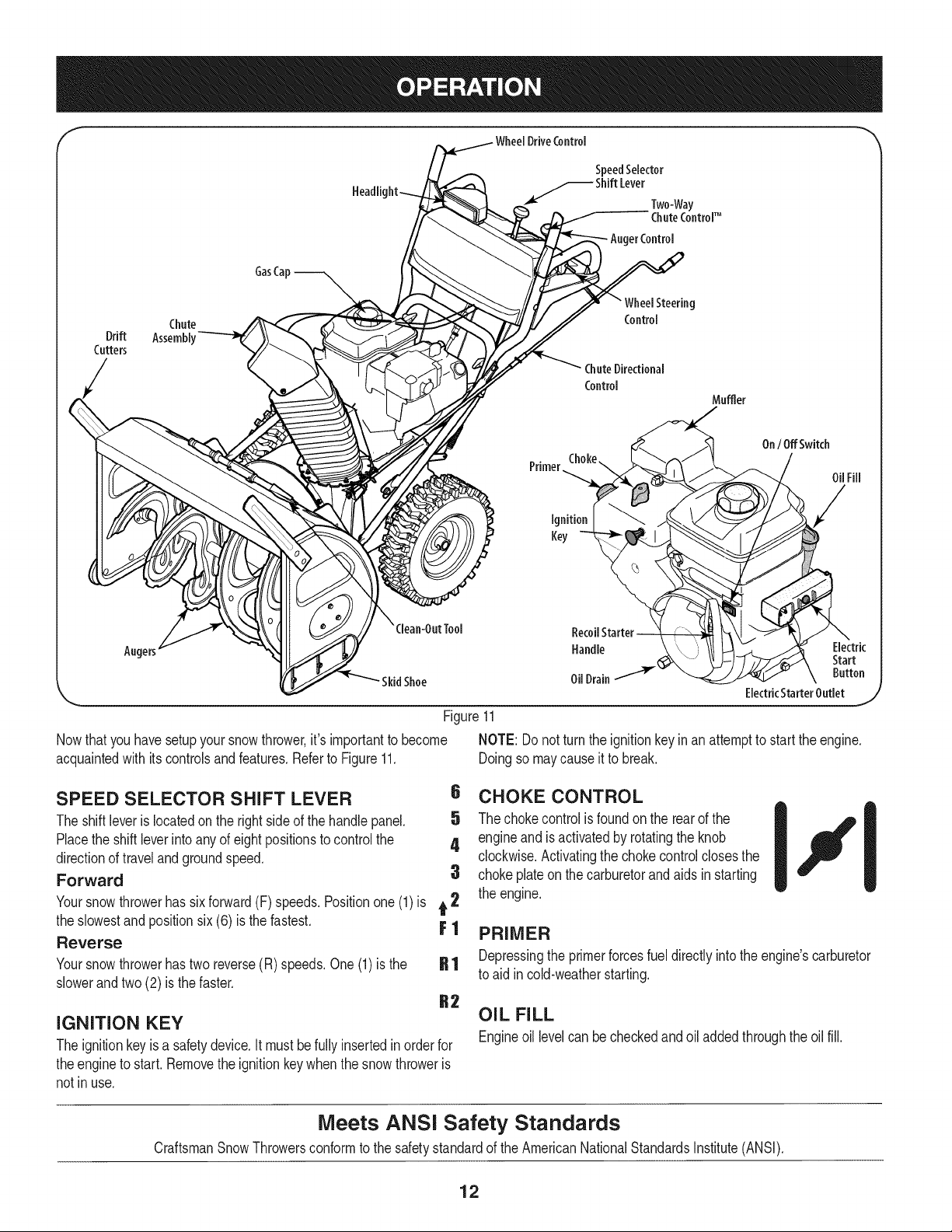
Nowthat youhavesetupyour snowthrower,it's importantto become
acquaintedwith itscontrolsand features.Referto Figure11.
Primer
Ignition
Key
OilFill
Handle Electric
Start
OilDrain -'_( Button
ElectricStarter Outlet
J
Figure11
NOTE: Donot turnthe ignitionkey in an attemptto startthe engine.
Doingso may causeit to break.
SPEED SELECTOR SHIFT LEVER
The shiftleveris locatedonthe rightsideof the handlepanel.
Placethe shiftleverinto anyof eightpositionsto controlthe
directionof travel and groundspeed.
Forward
Yoursnowthrowerhas six forward(F) speeds.Positionone(1)is t 2
the slowestand positionsix (6) is the fastest. F 1
Reverse
Yoursnowthrowerhastwo reverse(R) speeds.One(1)is the
slowerandtwo(2) is the faster.
IGNITION KEY
The ignitionkey is a safetydevice.It mustbefullyinsertedinorderfor
theengineto start. Removethe ignitionkey whenthe snowthroweris
not in use.
6 CHOKE CONTROL
5 The chokecontrolis foundon the rearof the
4 engineand is activatedby rotatingthe knob
clockwise.Activatingthe choke controlclosesthe
3 chokeplateonthe carburetorand aidsin starting
the engine.
PRIMER
Depressingthe primerforcesfueldirectlyintothe engine'scarburetor
to aid incold-weatherstarting.
OIL FILL
Engineoil levelcan becheckedandoiladdedthroughthe oil fill.
Meets ANSI Safety Standards
CraftsmanSnowThrowersconformto the safetystandardof the AmericanNationalStandardsInstitute(ANSI).
12
ON / OFF SWITCH
Pressinto theON positionwhenstartingthe engineand willshutoff
the enginewhenmovedintothe OFFposition.
RECOIL STARTER HANDLE
Thishandleis usedto manuallystartthe engine.
ELECTRIC STARTER BUTTON
Pressingthe electricstarterbuttonengagesthe engine'selectric
starterwhenpluggedintoa 120Vpowersource.
ELECTRIC STARTER OUTLET
Requiresthe useof a three-prongoutdoorextensioncord(included)
anda 120Vpowersource/walloutlet.
f
NOTE:Alwaysreleasethewheeldrivecontrolbeforechanging
speeds.Failureto do sowill result in increasedwearon yourmachine's
drive system.
AUGERS
Whenengaged,the augersrotateanddrawsnowintothe auger
housing.
CHUTE ASSEMBLY
Snowdrawninto theauger housingis dischargedout the chute
assembly.
GAS CAP
Unthreadthe gascap to add gasolineto the fuel tank.
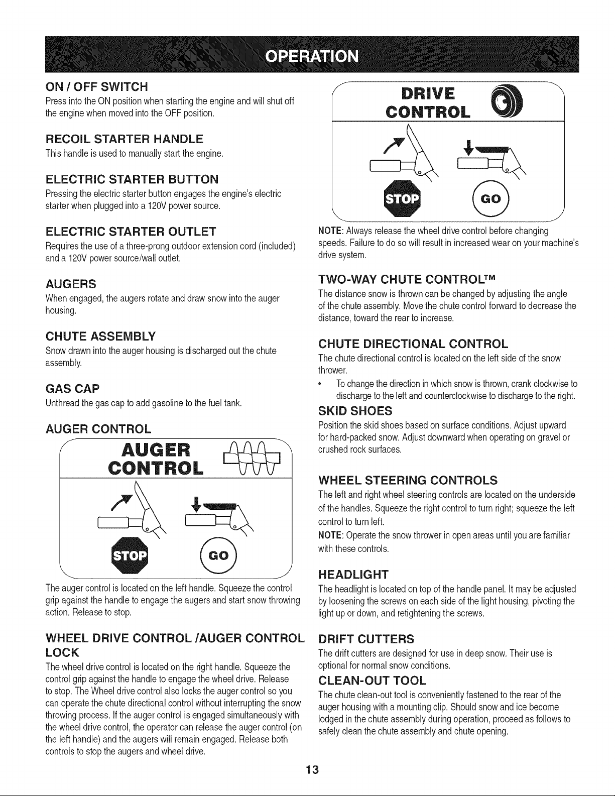
AUGER CONTROL
S
J
Theaugercontrolis locatedon the left handle.Squeezethecontrol
gripagainstthe handleto engagetheaugersandstart snowthrowing
action.Releaseto stop.
TWO-WAY CHUTE CONTROL TM
The distancesnow is throwncanbe changedby adjustingthe angle
of the chuteassembly.Movethe chutecontrolforwardto decreasethe
distance,towardthe rearto increase.
CHUTE DIRECTIONAL CONTROL
The chutedirectionalcontrol is locatedonthe left side of the snow
thrower.
• Tochangethedirectionin whichsnowisthrown,crankclockwiseto
dischargetothe left andcounterclockwiseto dischargeto the right.
SKID SHOES
Positionthe skid shoesbasedon surfaceconditions.Adjustupward
for hard-packedsnow.Adjustdownwardwhenoperatingon gravelor
crushedrocksurfaces.
WHEEL STEERING CONTROLS
The left and rightwheelsteeringcontrolsarelocatedon the underside
of the handles.Squeezethe rightcontrol to turn right;squeezethe left
controlto turnleft.
NOTE:Operatethe snowthrowerin openareasuntil youare familiar
withthesecontrols.
HEADLIGHT
The headlightis locatedontop of the handlepanel.It maybe adjusted
bylooseningthe screwson eachside of the lighthousing,pivotingthe
lightupor down,and retighteningthe screws.
WHEEL DRIVE CONTROL/AUGER CONTROL
LOCK
Thewheeldrivecontrolis locatedon the righthandle.Squeezethe
controlgripagainstthe handleto engagethewheeldrive.Release
to stop.TheWheeldrivecontrolalso locksthe augercontrolso you
canoperatethe chute directionalcontrolwithoutinterruptingthe snow
throwingprocess.If theaugercontrolis engagedsimultaneouslywith
the wheeldrivecontrol,the operatorcan releasetheaugercontrol(on
the left handle)and the augerswill remainengaged.Releaseboth
controlsto stop the augersandwheeldrive.
DRIFT CUTTERS
The drift cuttersare designedfor use indeepsnow.Theiruse is
optionalfor normalsnowconditions.
CLEAN-OUT TOOL
The chuteclean-outtool is convenientlyfastenedto the rearof the
augerhousingwitha mountingclip. Shouldsnowand ice become
lodgedinthe chute assemblyduringoperation,proceedas followsto
safelycleanthe chuteassemblyand chuteopening.
13
CLEAN-OUT TOOL
Neveruseyourhandsto cleara cloggedchuteassembly.Shut
off engineand remainbehindhandlesuntil all movingparts have
stoppedbeforeunclogging.
Thechuteclean-outtool is convenientlyfastenedto the rear of the
augerhousingwitha mountingclip. Shouldsnowandice become
lodgedin thechuteassemblyduringoperation,proceedas followsto
safelycleanthechuteassemblyandchuteopening:
1. Releaseboththe AugerControlandtheWheeldrivecontrol.
2. Stopthe engineby removingthe ignitionkey.
3. Removethe clean-outtoolfrom the clip whichsecuresit to the
rearof the augerhousing.
4. Use the shovel-shapedend of theclean-outtool to dislodgeand
scoopany snowand icewhich hasformedin andnearthechute
assembly.
5. Refastenthe clean-outtool to the mountingclip on the rearof
theaugerhousing,reinsertthe ignitionkey and startthe snow
thrower'sengine.
6. Whilestandingin the operator'sposition(behindthesnow
thrower),engagethe auger controlfora fewsecondsto clear any
remainingsnowandice from thechute assembly.
BEFORE STARTING ENGINE
Read,understand,and followall instructionsandwarningson the
machineand in this manualbeforeoperating.
Oil
The unitwas shippedwith oil inthe engine.Checkoil levelbeforeeach
operationto ensureadequateoil in the engine.Forfurther instructions,
referto the Service& Maintenancesectionof this manual.
1. Removethe dipstickfrom the oil fill.
2. Checkand makesurethatthe levelof oil is upto the FULLmark
onthe dipstick.
3. If the oil levelis not up to FULL,pourfreshmotoroil (5W-30,with
a minimumclassificationof SF/SG/SH/SJ)slowlythroughthe
opening.Replaceoil fill dipstickandcheckoil levelagain.
Gasoline
• Storegasolinein a clean, approvedcontainerandkeepthecap in
placeonthe container.
• Makesurethatthe containerfrom which youpour the gasolineis
cleanandfreefromrustor otherforeignparticles.
Useextremecarewhenhandlinggasoline.Gasolineis extremely
flammableand the vaporsareexplosive.Neverfuel the machine
indoorsor whilethe engineis hot or running.Extinguishcigarettes,
cigars,pipes andother sourcesof ignition.
NOTE:A plasticdust cap maybefoundinsidethe fuelfill opening.
Removeand discard,if present.
• Alwaysfill the fuel tank outdoorsand usea funnelor spoutto
preventspilling.
• Fillfuel tankwithclean,fresh,unleadedgasolinewith a minimum
of 85 octane.Freshfuel preventsgumfrom formingin the fuel
systemoronessentialcarburetorparts.Purchasefuelin a
quantitythatcan be usedwithin30 days.
• Neverfill the fuel tank completely.Fillthe tank to within1-1/2"
fromthe top to providespacefor expansionof fuel.
• Makesureto wipeoff anyspilledfuel beforestartingthe engine.
STARTING THE ENGINE
1. Makecertainboththe augercontrolandwheeldrivecontrolarein
the disengaged(released)position.
2. Insertignitionkey into slot.Makesure it snapsinto place.Do not
attemptto turn the key.
NOTE: Theenginecannot startwithoutthe keyis fully insertedintothe
ignitionswitch.
Electric Starter
Determinethat yourhome'swiringis a three-wiregroundedsystem.
Aska licensedelectricianif you are notcertain.
The optionalelectricstarteris equippedwitha groundedthree-wire
powercordandplug,and is designedto operateon 120volt AC
householdcurrent.It mustbe usedwith a properlygroundedthree-
prongreceptacleat all timesto avoidthe possibilityof electricshock.
Followall instructionscarefullypriorto operatingtheelectricstarter.
Ifyou havea groundedthree-prongreceptacle,proceedas follows:
1. Plugthe extensioncord intothe outletlocatedon the engine's
surface.Plugthe otherend of extensioncord intoa three-prong
120-volt,grounded,AC outlet in a well-ventilatedarea.
2. Rotatechokecontrolto FULL I,,q¢lchoke position(fora cold
enginestart).
NOTE: If the engineis alreadywarm,placechokecontrolin the OFF
I _ I positioninsteadof FULLIJl'
3. Depressprimer.If it is 15°For higher pushprimertwotimes,if
below 15°F,pushprimerfour times.
4. Pushrockerswitchto ONposition.
5. Pushstarterbuttonto startengine.
To prolongstarterlife, use shortstartingcycles (5 secondsmaximum
then waitone minute).
6. Once theenginestarts,releasestarterbutton.
7. Allowthe engineto warm up severalminutes,adjustingchoke
towardRUNposition.Waituntilenginerunssmoothlybeforeeach
chokeadjustment.
8. Whendisconnectingthe extensioncord,alwaysunplugtheend
at the three-prongwall outletbeforeunpluggingtheoppositeend
fromthe snowthrower.
14
Recoil Starter
1. Rotatechokecontrolto CHOKE Ill position.
2. Depressprimer.If it is 15°For higherpushprimertwotimes,if
below15°F,pushprimerfourtimes.
3. Pushrockerswitchto ONposition.
4. Graspthe recoilstarterhandleand slowlypull the ropeout. At
the pointwhereit becomesslightlyharderto pull the rope,slowly
allowthe ropeto recoil.
5. Pull the starterhandlewitha firm, rapidstroke.Donot release
the handleand allowit to snap back.Keepa firm hold on the
starterhandleandallowit to slowlyrecoil.
6. Allowtheengine to warmup severalminutes,adjustingchoke
towardRUNposition.Waituntilengineruns smoothlybeforeeach
chokeadjustment.
STOPPING THE ENGINE
Runenginefor a few minutesbeforestoppingto helpdry off any
moistureonthe engine.
1. Pushthe On / Off switchto the OFF position.
Do NOTmovethe chokecontrolto CHOKE IJl positionto stop
the engine.Backfireor enginedamagemayoccur.
.
3.
Removetheignitionkeyandstoreina safe place.
Wipeall snowandmoisturefrom thearea aroundthe engineas
wellas the areainandaroundthe wheeldrivecontroland auger
control.Also,engageandreleasebothcontrolsseveraltimes.
TO ENGAGE WHEEL DRIVE
1. Moveshift leverintoone of the six forward(F) positionsor two
reverse(R) positions.Selecta speedappropriatefor the snow
conditionsand a paceyou'recomfortablewith.
NOTE: Whenselectinga DriveSpeed,usethe slowerspeedsuntil
youarecomfortableandfamiliarwiththe operationof the snow
thrower.
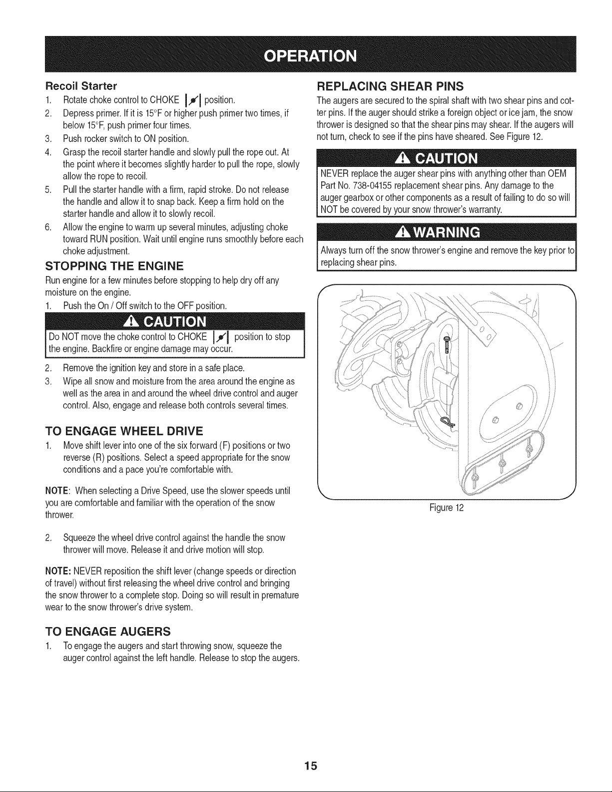
REPLACING SHEAR PINS
The augersare securedto the spiralshaftwithtwo shearpinsand cot-
ter pins. If theaugershouldstrikea foreignobjector icejam, thesnow
throweris designedso thatthe shearpinsmay shear.If the augerswill
notturn,checkto see if the pinshavesheared.SeeFigure12.
NEVERreplacethe augershearpinswith anythingotherthan OEM
PartNo.738-04155replacementshearpins.Any damageto the
augergearboxor othercomponentsas a resultof failingto do sowill
NOTbecoveredbyyour snowthrower'swarranty.
Alwaysturn off thesnowthrower'sengineand removethe keypriorto
replacingshearpins.
f
ii
Figure12
J
2. Squeezethe wheeldrivecontrolagainstthe handlethe snow
throwerwill move.Releaseit and drivemotionwill stop.
NOTE: NEVERrepositionthe shift lever(changespeedsordirection
of travel)withoutfirst releasingthe wheeldrivecontrolandbringing
the snowthrowerto a completestop.Doingso will resultinpremature
wearto the snowthrower'sdrive system.
TO ENGAGE AUGERS
1. Toengagethe augersand start throwingsnow,squeezethe
augercontrolagainstthe left handle.Releaseto stop the augers.
15
ENGINE MAINTENANCE
Beforelubricating,repairing,or inspecting,disengageallcontrolsand
stopengine.Waituntilallmovingpartshavecometo a completestop.
Removetheignitionkeyto preventunintendedfiringof theengine.
Checking Engine Oil
1. Be sureengine isuprightand level
2. Unscrewoil fill capfrom oil fillertubeandwipe dipstickclean.
3. Screwoil fill capback intooil fillertube.Tightensecurely.
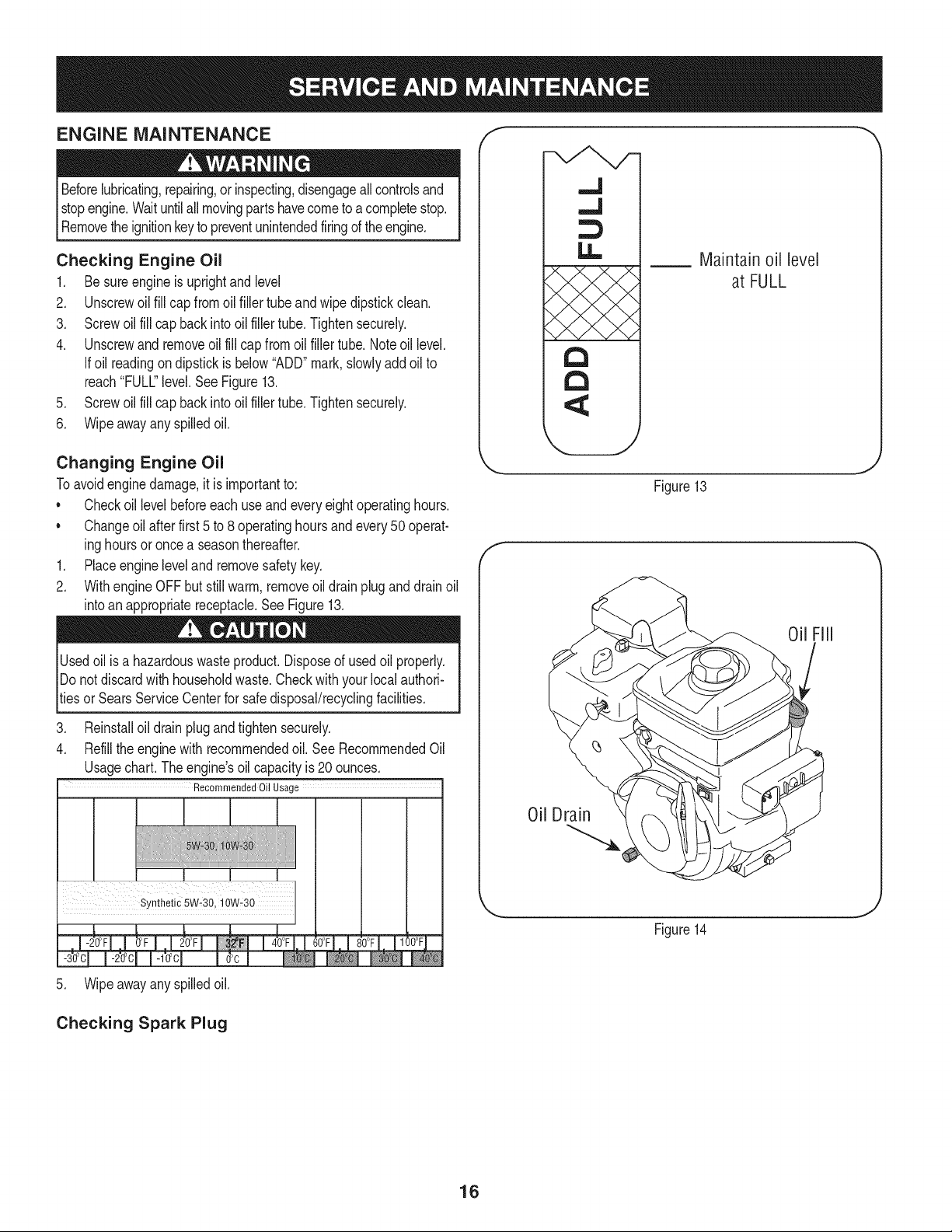
4. Unscrewand removeoilfill cap from oil filler tube.Noteoil level.
Ifoil readingondipstickisbelow"ADD"mark,slowlyadd oil to
reach"FULL"level.SeeFigure13.
5. Screwoil fill capback intooil fillertube.Tightensecurely.
6. Wipeawayany spilledoil.
Changing Engine Oil
Toavoidenginedamage,it is importantto:
• Checkoil levelbeforeeachuseandeveryeightoperatinghours.
• Changeoil afterfirst 5 to 8 operatinghoursand every50operat-
inghoursor oncea seasonthereafter.
1. Placeengineleveland removesafety key.
2. Withengine OFF butstill warm,removeoil drainpluganddrainoil
intoan appropriatereceptacle.See Figure13.
Usedoilisa hazardouswasteproduct.Disposeof usedoil properly.
IDonot discardwith householdwaste.Checkwithyourlocalauthori-
_tiesor SearsServiceCenterfor safedisposal/recyclingfacilities.
3. Reinstalloil drain plug and tightensecurely.
4. Refillthe enginewith recommendedoil. See RecommendedOil
Usagechart.The engine'soil capacityis 20 ounces.
Recommended Oil Usage
f
f
,.J
..J
LI..
a
a
Maintain oil level
at FULL
X._j
Figure13
Oil Drain
J
i¸ i!i!i¸iii¸,!i!i
Figure14
5. Wipeawayany spilledoil.
Checking Spark Plug
16
Checksparkplugyearlyor every100operatinghours.
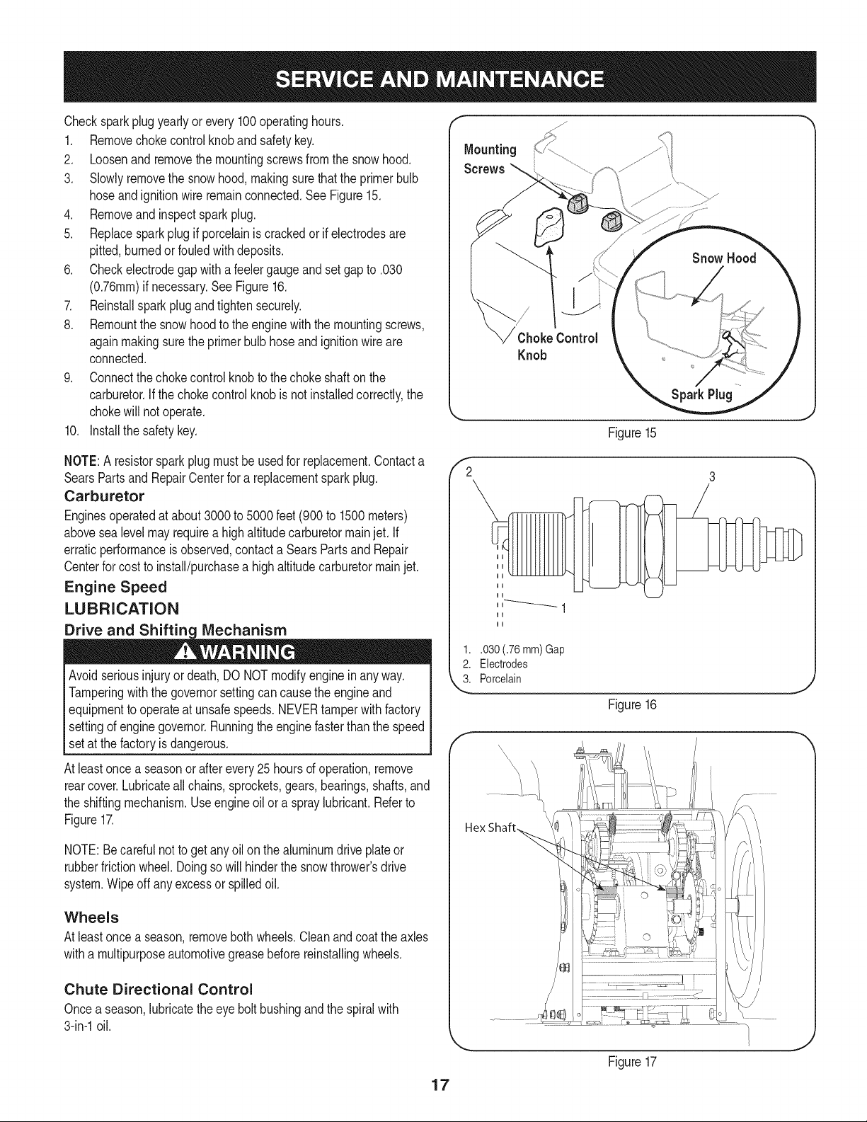
1. Removechokecontrolknobandsafetykey.
2. Loosenand removethe mountingscrewsfromthe snowhood.
3. Slowlyremovethe snowhood,makingsurethatthe primerbulb
hoseandignitionwireremainconnected.SeeFigure15.
4. Removeand inspectspark plug.
5. Replacesparkplug if porcelainis crackedor if electrodesare
pitted,burnedorfouledwithdeposits.
6. Checkelectrodegap with a feelergaugeandsetgapto .030
(0.76ram)if necessary.SeeFigure16.
7. Reinstallspark plugand tightensecurely.
8. Remountthe snowhoodto the enginewith themountingscrews,
againmakingsurethe primerbulb hoseandignitionwireare
connected.
9. Connectthe chokecontrolknobto thechokeshaftonthe
carburetor.If the chokecontrolknobis not installedcorrectly,the
chokewill notoperate.
10. Installthe safetykey.
NOTE:A resistorsparkplug mustbe usedfor replacement.Contacta
SearsPartsand RepairCenterfor a replacementsparkplug.
Carburetor
Enginesoperatedat about3000 to 5000feet(900to 1500meters)
abovesealevelmayrequireahighaltitudecarburetormainjet. If
erraticperformanceis observed,contacta SearsPartsand Repair
Centerfor costto install/purchasea highaltitudecarburetormainjet.
Engine Speed
LUBRICATION
Drive and Shifting Mechanism
Avoidseriousinjuryor death,DO NOTmodifyenginein anyway.
Tamperingwiththe governorsettingcancause theengine and
equipmentto operateat unsafespeeds.NEVERtamperwith factory
settingof enginegovernor.Runningthe enginefasterthanthe speed
setat thefactoryis dangerous.
At leastonce a seasonor after every25 hoursof operation,remove
rearcover.Lubricateallchains,sprockets,gears,bearings,shafts,and
the shiftingmechanism.Useengineoil ora spray lubricant.Referto
Figure17.
NOTE:Becarefulnotto get anyoil on thealuminumdrive plateor
rubberfrictionwheel.Doingso will hinderthe snowthrower'sdrive
system.Wipeoff anyexcessor spilledoil.
Wheels
At leastonce a season,removeboth wheels.Cleanandcoattheaxles
witha multipurposeautomotivegreasebeforereinstallingwheels.
Chute Directional Control
Oncea season,lubricatethe eye boltbushingandthe spiralwith
3-in-1oil.
Mounting
Screws
Knob
Figure15
f
Figure16
17
Figure17
Auger Shaft
Atleastonceaseason,removetheshearpinsonaugershaft.Spray
lubricantinsideshaft,andaroundthespacersandflangebearings
foundateitherendoftheshaft.SeeFigure18.
SHAVE PLATE AND SKID SHOES
The shaveplateand skidshoesonthe bottomof the snowthrowerare
subjectto wear.They shouldbe checkedperiodicallyand replaced
whennecessary.
Skid Shoes
NOTE:Theskidshoeson thismachinehavetwowearedges.When
onesidewearsout,theycan be rotated1800to usethe otheredge.
1. Removethe sixcarriageboltsandhexnutsthatsecurethe two
skidshoesto the sidesof theauger housing.Referto Figure19.
2. Positionthe new skidshoesandsecurewiththe carriagebolts
andhexnuts. Makecertainthe skidshoesareadjustedto be
level.
Shave Plate
1. Removethe hexnutsandcarriageboltsthatsecurethe shave
plateto the bottomof the housing.
2. Removethe rearmost hexnut andcarriagebolt securingthe back
of eachskid shoeto the sidesof the housing.Loosenthefour
remaininghexnutssecuringthe skid shoes.
3. Slidethe shaveplateout of the off-setslotatthe bottomof the
housing,andfrombetweenthe skid shoesand side panelsof the
housing.
4. Withthe mountingholestowardthe backof the unit,slidethe new
shaveplateinto positionand securewiththe fastenersremoved
previously.
ADJUSTMENTS
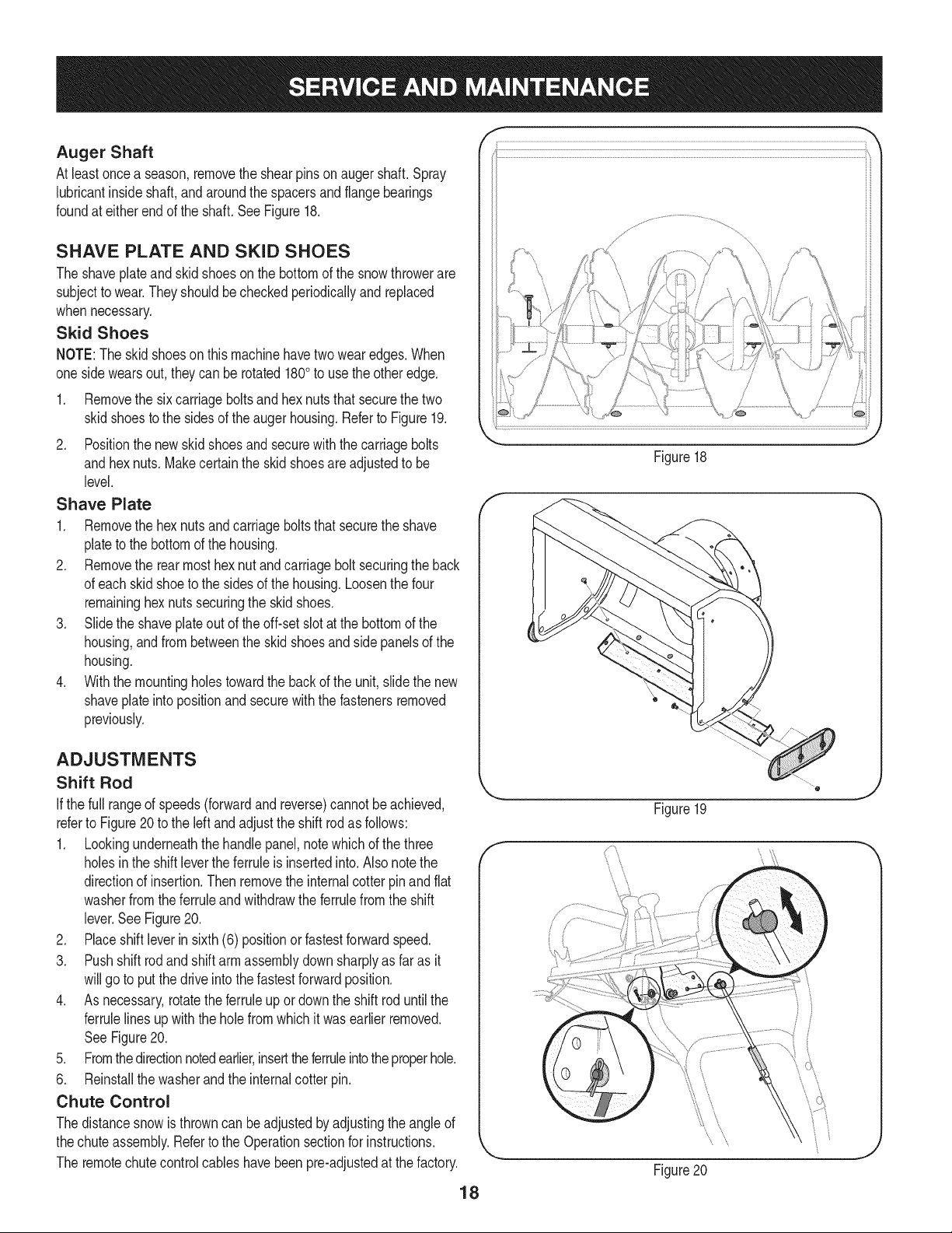
Shift Rod
Ifthe full rangeof speeds(forwardandreverse)cannotbe achieved,
referto Figure20 to the left and adjust the shift rodas follows:
1. Lookingunderneaththe handlepanel,notewhichof thethree
holesinthe shiftleverthe ferruleis insertedinto.Also notethe
directionof insertion.Thenremovethe internalcotter pin and flat
washerfromthe ferruleand withdrawtheferrulefrom the shift
lever.SeeFigure20.
2. Placeshift leverin sixth (6) positionor fastestforwardspeed.
3. Pushshift rodandshiftarm assemblydownsharplyas far as it
willgo to put the driveintothe fastestforwardposition.
4. As necessary,rotatethe ferruleupor downthe shiftrod untilthe
ferrulelinesupwiththe hole from whichit wasearlier removed.
SeeFigure20.
5. Fromthedirectionnotedearlier,inserttheferruleintothe properhole.
6. Reinstallthe washerandthe internalcotter pin.
Chute Control
Thedistancesnowis throwncan beadjustedby adjustingthe angleof
thechuteassembly.Referto the Operationsectionfor instructions.
The remotechutecontrol cableshavebeen preladjustedat the factory.
18
f
f
/ /7 "'! ......_, .....
.............. _':'f!'t, .......... }_\_. _,
i _ \ .....77',!.1< ' L _k;,..... +El'\t;......
k, -Jr 7 r'W'i / '
, , _ ' ...... 7
....................,'r......................................\ i ........ +>, F .............................
J
Figure18
Figure19
t,
' ii /
Figure20
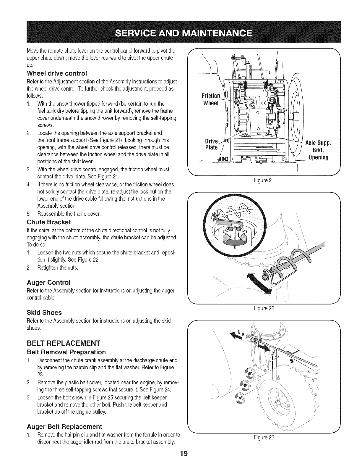
Movetheremotechuteleveronthecontrolpanelforwardtopivotthe
upperchutedown;movetheleverrearwardtopivottheupperchute
up,
Wheel drive control
RefertotheAdjustmentsectionoftheAssemblyinstructionstoadjust
thewheeldrivecontrol,Tofurtherchecktheadjustment,proceedas
follows:
1. Withthesnowthrowertippedforward(becertaintorunthe
fueltankdrybeforetippingtheunitforward),removetheframe
coverunderneaththesnowthrowerbyremovingtheself-tapping
screws.
2. Locatetheopeningbetweentheaxlesupportbracketand
thefrontframesupport(SeeFigure21).Lookingthroughthis
opening,withthewheeldrivecontrolreleased,theremustbe
clearancebetweenthefrictionwheelandthedriveplateinall
positionsoftheshiftlever.
3. Withthewheeldrivecontrolengaged,thefrictionwheelmust
contactthedriveplate.SeeFigure21.
4. Ifthereisnofrictionwheelclearance,orthefrictionwheeldoes
notsolidlycontactthedriveplate,re-adjustthelocknutonthe
lowerendofthedrivecablefollowingtheinstructionsinthe
Assemblysection.
5. Reassembletheframecover.
Chute Bracket
Ifthespiralatthebottomofthechutedirectionalcontrolisnotfully
engagingwiththe chuteassembly,the chute bracketcan beadjusted.
Todo so:
1. Loosenthe two nuts which securethechute bracketand reposi-
tion it slightly.See Figure22.
2. Retightenthe nuts.
Auger Control
Referto the Assemblysectionfor instructionsonadjustingtheauger
controlcable.
Skid Shoes
Referto the Assemblysectionfor instructionsonadjustingthe skid
shoes.
BELT REPLACEMENT
Belt Removal Preparation
1. Disconnectthe chutecrankassemblyat the dischargechute end
by removingthe hairpinclipandthe flat washer.Referto Figure
23.
2. Removetheplasticbelt cover,locatednearthe engine,by remov-
ingthe threeself-tappingscrewsthatsecureit. SeeFigure24.
3. Loosenthe bolt shownin Figure25 securingthe belt keeper
bracketandremovetheother bolt. Pushthe belt keeperand
bracketupoff the enginepulley.
Auger Belt Replacement
1. Removethehairpinclip and flat washerfrom theferrulein orderto
disconnectthe augeridler rod from the brakebracketassembly.
f
Drive Axle Supp.
Plate Brkt.
Opening
Figure21
l
j_
Figure22
Figure23
19
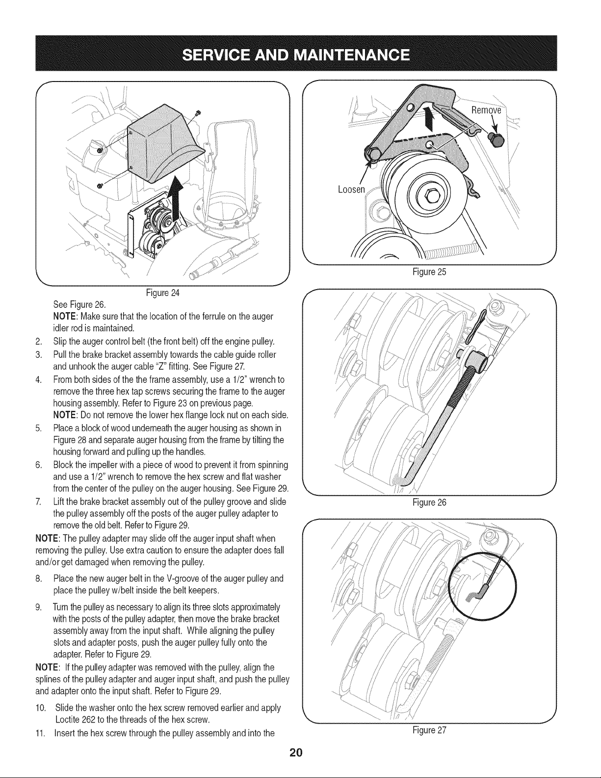
Figure24
SeeFigure26.
NOTE:Makesurethatthe locationof the ferruleon the auger
idlerrodis maintained.
2. Slip the augercontrolbelt (thefront belt) offthe enginepulley.
3. Pull the brakebracketassemblytowardsthecable guide roller
andunhookthe augercable"Z" fitting.See Figure27.
4. Fromboth sidesof the the frameassembly,use a 1/2" wrenchto
removethe threehex tap screwssecuringthe frameto the auger
housingassembly.Referto Figure23on previouspage.
NOTE:Do not removethe lowerhexflangelock nuton eachside.
5. Placea blockof woodunderneaththe augerhousingas shownin
Figure28andseparateaugerhousingfromtheframeby tiltingthe
housingforwardand pullingupthe handles.
6. Blockthe impellerwitha piece of woodto preventit fromspinning
andusea 1/2"wrenchto removethe hexscrewandflatwasher
fromthe centerof the pulleyonthe auger housing.See Figure29.
7. Lift the brakebracketassemblyout of the pulleygrooveandslide
the pulleyassemblyoff the postsof the augerpulleyadapterto
removetheoldbelt.Referto Figure29.
NOTE:Thepulleyadaptermay slideoff the augerinputshaftwhen
removingthe pulley.Useextra cautionto ensurethe adapterdoes fall
and/orget damagedwhenremovingthe pulley.
8. Placethe newaugerbeltin theV-grooveof the augerpulleyand
placethe pulleyw/beltinsidethe belt keepers.
9. Turnthe pulleyas necessarytoalignits threeslotsapproximately
withthepostsofthe pulleyadapter,thenmovethe brakebracket
assemblyawayfromthe inputshaft. Whilealigningthe pulley
slotsandadapterposts,pushthe augerpulleyfullyontothe
adapter.Referto Figure29.
NOTE: If the pulleyadapterwas removedwiththe pulley,alignthe
splinesof the pulleyadapterandaugerinputshaft,andpushthe pulley
andadapterontothe inputshaft. Referto Figure29.
10. Slide thewasherontothe hex screwremovedearlier and apply
Loctite262to the threadsof the hexscrew.
11. Insertthe hex screwthroughthepulleyassemblyand into the
Loosen
Figure25
Figure26
//
f
/
//
/
/
Figure27
20
threadsof the inputshaft.Torquethe hex screwto 250-325 in.
/Ibs.to securethe augerpulleyassemblyonthe input shaft.
12. If also replacingthe drivebelt,proceedto the "DriveBelt"
instruction.If not,repositionthe transmissionframebackonto
the auger housing.Installthe drivebelton theengine pulley,
re-connectthe augercable"Z" fittingandaugeridler rodferrule
to the brakebracket.Repositionand securethe enginepulley
beltguard,andre-installthe belt cover.
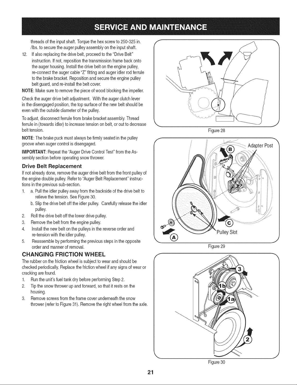
NOTE:Makesureto removethe pieceof woodblockingthe impeller.
Checktheaugerdrivebeltadjustment. Withtheaugerclutch lever
in thedisengagedposition,the top surfaceof the newbelt shouldbe
evenwiththe outsidediameterof the pulley.
Toadjust,disconnectferrulefrombrakebracketassembly.Thread
ferrulein(towardsidler)to increasetensionon belt,or out to decrease
belttension.
NOTE:Thebrakepuckmustalwaysbe firmlyseatedinthe pulley
groovewhenaugercontrolis disengaged.
IMPORTANT:Repeatthe "AugerDriveControlTest"fromthe As-
semblysectionbeforeoperatingsnowthrower.
Drive Belt Replacement
If notalreadydone,removethe augerdrivebelt from thefront pulleyof
the enginedoublepulley.Referto "AugerBeltReplacement"instruc-
tionsinthe previoussub-section.
1. a. Pull the idlerpulleyawayfrom the backsideof the drivebeltto
relievethe tension.See Figure30.
b. Slip the drivebelt off the idlerpulley. Carefullyreleasethe idler
pulley.
2. Rollthe drive beltoff the lowerdrive pulley.
3. Removethe beltfrom the enginepulley.
4. Installthe newbelt onthe pulleysinthe reverseorderand
re-tensionwiththe idlerpulley.
5. Reassembleby performingthe previousstepsinthe opposite
orderandmannerof removal.
CHANGING FRICTION WHEEL
The rubberon the frictionwheelis subjectto wearand shouldbe
checkedperiodically.Replacethe frictionwheelifany signsof wearor
crackingarefound.
1. Runthe unit'sfuel tankdry beforeperformingStep2.
2. Tip thesnowthrowerupandforward,so thatit restson the
housing.
3. Removescrewsfrom the framecoverunderneaththesnow
thrower(referto Figure31). Removethe rightwheelfrom the axle.
Figure28
Adapter Post
f
Slot
Figure29
Figure30
21
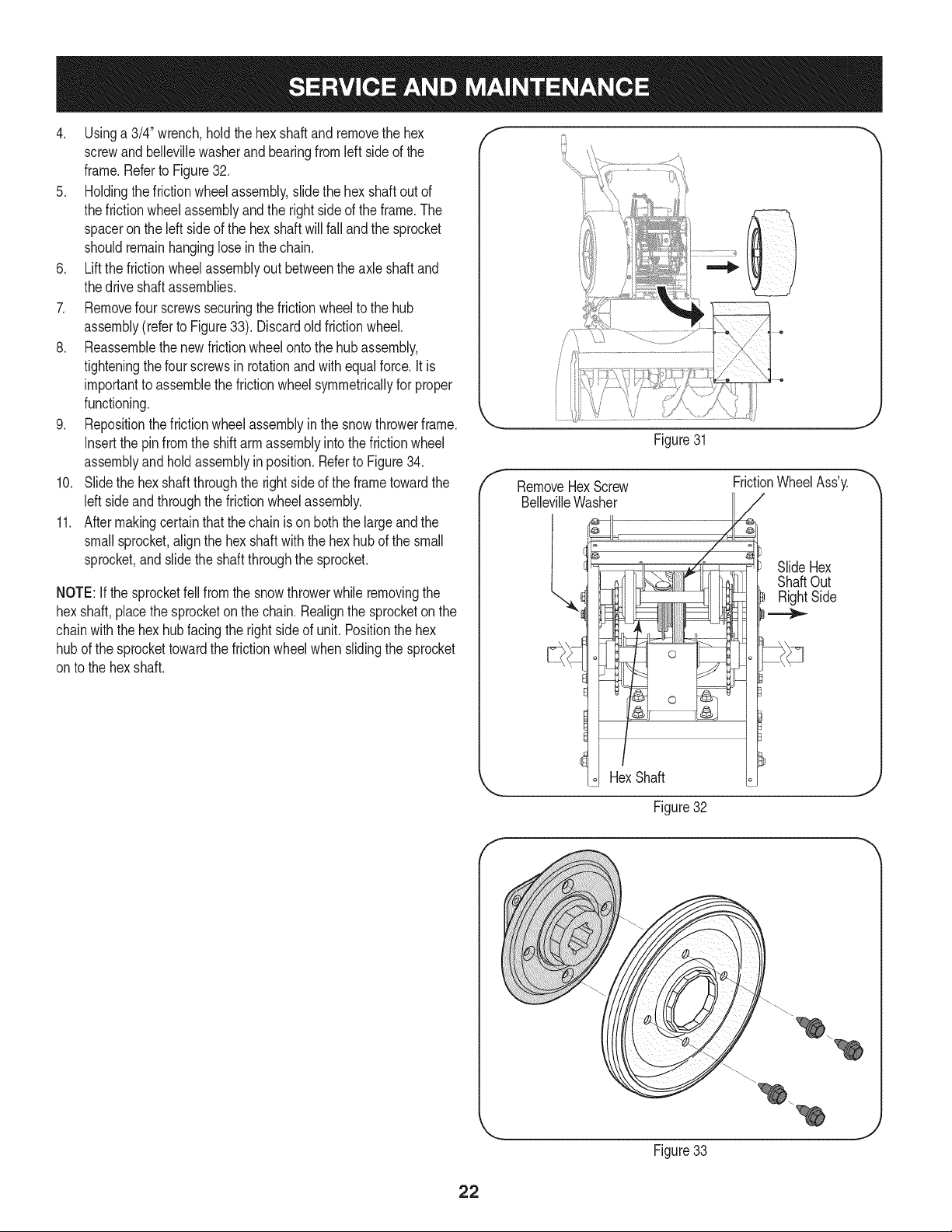
4. Usinga 3/4" wrench,hold the hex shaftandremovethe hex
screwandbellevillewasherand bearingfromleft sideof the
frame.Referto Figure32.
5. Holdingthe frictionwheelassembly,slidethe hex shaftoutof
thefrictionwheelassemblyandthe rightsideof the frame.The
spaceronthe left sideof the hex shaftwill fallandthe sprocket
shouldremainhanginglosein the chain.
6. Lift the frictionwheelassemblyout betweenthe axle shaftand
thedrive shaftassemblies.
7. Removefour screwssecuringthe frictionwheelto the hub
assembly(referto Figure33). Discardold frictionwheel.
8. Reassemblethe newfrictionwheelontothe hub assembly,
tighteningthe fourscrewsin rotationandwith equalforce.It is
importantto assemblethefrictionwheelsymmetricallyfor proper
functioning.
9. Repositionthe frictionwheelassemblyin the snowthrowerframe.
Insertthe pin from the shiftarm assemblyintothe frictionwheel
assemblyandholdassemblyin position.Referto Figure34.
10. Slidethe hexshaftthroughthe rightsideof the frametowardthe
leftside and throughthe frictionwheelassembly.
11. Aftermakingcertain that the chainis on boththe largeand the
smallsprocket,align the hexshaftwith thehex hubof the small
sprocket,andslidethe shaftthroughthe sprocket.
NOTE:If thesprocketfellfromthe snowthrowerwhile removingthe
hexshaft,placethe sprocketon thechain.Realignthe sprocketon the
chainwiththe hexhub facingthe rightsideof unit.Positionthe hex
hubof the sprockettowardthe frictionwheelwhen slidingthe sprocket
onto the hex shaft.
Figure31
RemoveHexScrew
BellevilleWasher
l°
HexShaft
/
FrictionWheelAss'y.
SlideHex
ShaftOut
RightSide
Figure32
J
f
Figure33
22
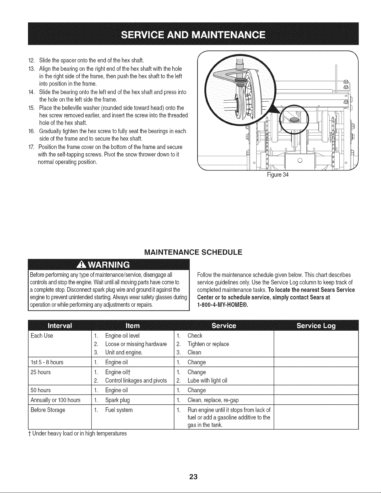
12. Slidethe spaceronto theend of the hex shaft.
13. Alignthe bearingonthe rightendof the hexshaftwiththe hole
in the rightsideof theframe,thenpushthe hex shaftto the left
into positionin the frame.
14. Slidethe bearingontothe left end of thehex shaftandpressinto
the hole on the Idt sidethe frame.
15. Placethe bellevillewasher(roundedsidetowardhead)onto the
hex screwremovedearlier,and insertthe screwintothe threaded
holeof the hex shaft.
16. Graduallytightenthe hex screwto fully seatthe bearingsin each
side of theframeandto securethe hexshaft.
17. Positionthe framecoveronthe bottomof theframeandsecure
withthe self-tappingscrews.Pivotthe snowthrowerdownto it
normaloperatingposition.
©
Figure34
MAINTENANCE SCHEDULE
Beforeperforminganytypeof maintenance/service,disengageall
controlsandstoptheengine.Waituntilall movingpartshavecometo
acompletestop.Disconnectsparkplugwireandgroundit againstthe
engineto preventunintendedstarting.Alwayswearsafetyglassesduring
operationorwhileperforminganyadjustmentsor repairs.
Followthe maintenanceschedulegivenbelow.Thischartdescribes
serviceguidelinesonly.Usethe ServiceLog columnto keeptrackof
completedmaintenancetasks.To locate the nearestSears Service
Centeror to scheduleservice,simplycontactSearsat
1-800-4-MY-HOME®.
Each Use
1st5- 8 hours
25 hours
50 hours
Annuallyor 100hours
BeforeStorage
1 Underheavyloadorin high temperatures
1. Engineoil level
2. Looseor missinghardware
3. Unit and engine.
1. Engineoil
1. Engineoi11-
2. Controllinkagesand pivots
1. Engineoil
1. Sparkplug
1. Fuelsystem
= =
1. Check
2. Tightenor replace
3. Clean
1. Change
1. Change
2. Lubewith lightoil
1. Change
1. Clean,replace,re-gap
1. Runengine untilit stopsfrom lack of
fuel or add a gasolineadditiveto the
gas in the tank.
23
Ifthe snowthrowerwillnot be usedfor30 daysor longer,or if it is the end of the snowseasonwhenthe lastpossibilityof snowis gone,the
equipmentneedsto be storedproperly.Followstorageinstructionsbelowto ensuretop performancefromthe snowthrowerfor manymoreyears.
PREPARING ENGINE
Forenginesstoredover30days:
1. Topreventgum fromforminginfuel systemoron essentialcarbure-
tor parts:
a. If fueltankcontainsoxygenatedor rdormulatedgasoline
(gasolineblendedwithan alcoholorether),runengineuntilit stops
fromlackof fuel.
Alcoholblendedfuels(calledgasoholor usingethanolor methanol)
canattractmoisturewhich leadsto separationandformationof acids
duringstorage.Acidicgas can damagethefuel systemof an engine
_wh e n storage.
b. If fueltankcontainsgasoline,eitherrun engineuntilit stopsfrom
lackof fuel oradda gasolineadditiveto the gas in the tank. If you
usea gas additive,runthe enginefor severalminutesto circulate
theadditivethroughthecarburetor.
Neverstoresnowthrowerwithfuel in tank indoorsor in poorlyventi-
latedareas,wherefuel fumesmay reachan openflame,sparkor pilol
lightas on a furnace,water heater,clothesdryer or gas appliance.
.
3.
Whiletheengineis still warm,changethe oil.
Removethe sparkplug and pourabout 1/2 ounceof engineoil
throughthe sparkplug hole into the cylinder.Replacesparkplug
andcrankthe engineseveraltimesto distributethe oil.
PREPARING SNOW THROWER
• Whenstoringthe snowthrowerin an unventilatedormetalstor-
age shed,careshouldbetakento rustprooftheequipment.Using
a light oilor silicone,coat theequipment,especiallyanychains,
springs,bearingsandcables.
• Removealldirt fromexteriorof engineand equipment.
• Followlubricationrecommendations.
• Storeequipmentin a clean,dry area.
Neveruseengineor carburetorcleaningproductsin the fueltankor
permanentdamagemayoccur.
24
Beforeperforminganytyped maintenance/service,disengageall
controlsandstoptheengine.Waituntilallmovingpartshavecometo
a completestop.Disconnectsparkplugwireandgroundit againstthe
engineto preventunintendedstarting.Alwayswearsafetyglassesduring
operationorwhileperforminganyadjustmentsorrepairs.
Thissectionaddresses minor service issues.To locate the nearestSearsServiceCenteror to scheduleservice,simplycontactSears
at 1-800-4-MY-HOME®.
Enginefailsto start
Enginerunserratically
1. Chokecontrolnot in ONposition.
2. Sparkplug wiredisconnected.
3. Faultysparkplug.
4. Fueltank emptyor stalefuel.
5. Enginenot primed.
6. Safetykey not inserted.
1. Enginerunningon CHOKE.
2. Stalefuel.
3. Wateror dirt in fuel system.
4. Carburetoroutof adjustment.
1. Carburetornotadjustedproperly.
1. Looseparts or damagedauger.
Engineoverheats
Excessivevibration
Lossof power 1. Sparkplugwireloose.
2. Gascap ventholeplugged.
Unitfailsto propelitself 1. Drivecablein needof adjustment.
Unitfailsto dischargesnow
2. Drivebeltlooseor damaged.
3. Frictionwheelworn.
1. Chuteassemblyclogged.
2. Foreignobjectlodgedin auger.
3. Augercable inneedof adjustment.
4. Auger beltlooseor damaged.
5. Shear pin(s)sheared.
1. Movechoke controlto ON position.
2. Connectwireto sparkplug.
3. Clean,adjustgap, or replace.
4. Filltank with clean,fresh gasoline.
5. Primeengineas instructedin theOperationSection.
6. Insertkey fully intothe switch.
1. Movechoke controlto OFFposition.
2. Filltank with clean,fresh gasoline.
3. Drainfuel tank.Refillwithfreshfuel.
4. ContactyourSearsParts & RepairCenter.
1. ContactyourSearsParts& RepairCenter.
1. Stopengineimmediatelyanddisconnectsparkplug
wire.Tightenall boltsandnuts.If vibrationcontinues,
haveunit servicedby a SearsParts& RepairCenter.
1. Connectandtightensparkplugwire.
2. Removeice and snowfrom gas cap.Becertainvent
holeis clear.
1. Adjustdrivecontrolcable.Referto Serviceand
Maintenancesection.
2. Replacedrivebelt. Referto Service&Maint.section.
3. Replacefrictionwheel.
1. Stopengineimmediatelyanddisconnectsparkplug
wire.Cleanchuteassemblyandinsideof auger
housingwithclean-outtoolor a stick.
2. Stopengine immediatelyand disconnectspark plug
wire.Removeobject from augerwith clean-outtool
or a stick.
3. Adjustauger controlcable. Referto Assembly
section.
4. Replaceaugerbelt. Referto Serviceand Mainte-
nancesection.
5. Replacewith newshearpin(s).
HEED MORE HELP?
_ _r@ the answe_ and more on _an_my_eE_eo_e_ _ _ f_e_!
o Find this and all your other product manuals onLLne.
o Get answers from our team of home experts.
o Get a personalized maintenance plan for your home,
o Find information and tools to help w}th home projects.
25
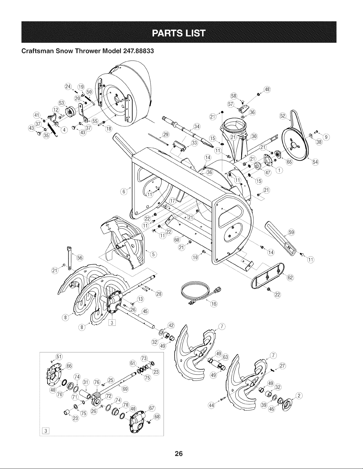
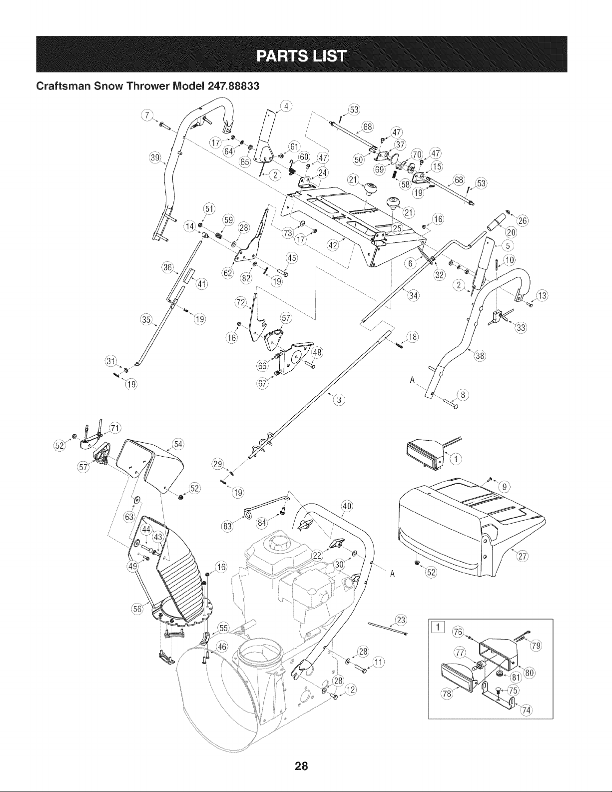
Craftsman Snow Thrower Model 247.88833
)
26
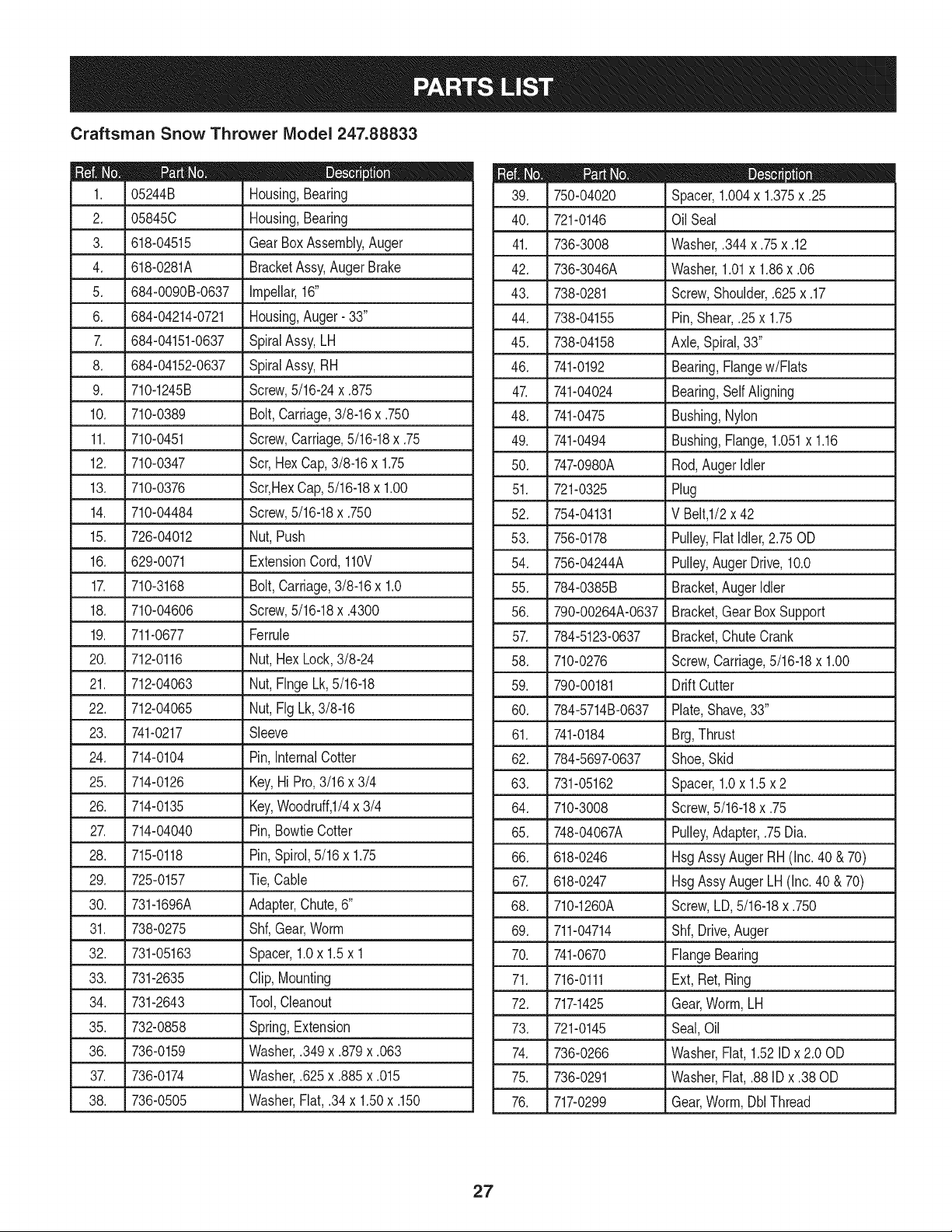
Craftsman Snow Thrower IViodel 247.88833
D = 0
05244B Housing,Bearing
2. 05845C Housing,Bearing
3. 618-04515 GearBoxAssembly,Auger
4. 618-0281A BracketAssy,AugerBrake
5. 684-0090B-0637 Impellar,16"
6. 684-04214-0721 Housing,Auger- 33"
7. 684-04151-0637 SpiralAssy,LH
8. 684-04152-0637
9. 710-1245B
10. 710-0389
11. 710-0451
12. 710-0347
13. 710-0376
14. 710-04484
SpiralAssy,RH
Screw,5/16-24x .875
Bolt,Carriage,3/8-16x .750
Screw,Carriage,5/16-18x .75
Scr,HexCap,3/8-16x 1.75
Scr,HexCap,5/16-18x 1.00
Screw,5/16-18x .750
15. J 726-04012 J Nut, Push
16. 629-0071 ExtensionCord,110V
17. 710-3168 Bolt, Carriage,3/8-16x 1.0
18. 710-04606 Screw,5/16-18x .4300
19. 711-0677 Ferrule
20. 712-0116 Nut, HexLock,3/8-24
21. 712-04063 Nut, FlngeLk,5/16-18
22. 712-04065 Nut, Fig Lk,3/8-16
23. 741-0217 Sleeve
24. 714-0104 Pin, internalCotter
25. 714-0126 Key,Hi Pro,3/16x 3/4
26. 714-0135 Key,Woodruff,I/4x 3/4
27. 714-04040 Pin, BowtieCotter
28. 715-0118 Pin,Spirol,5/16x 1.75
29. 725-0157 Tie, Cable
30. 731-1696A Adapter,Chute,6"
31. .738-0275 , Shf,Gear,Worm
32. 731-05163 Spacer,1.0x 1.5x 1
33. 731-2635 Clip, Mounting
34. 731-2643 Tool,Cleanout
35. 732-0858 Spring,Extension
36. 736-0159 Washer,.349x .879x .063
37. 736-0174 Washer,.625x .885x .015
38. 736-0505 Washer,Fiat, .34x 1.50x .150
D = O g
750-04020 Spacer,1.004x 1.375x .25
40. 721-0146 Oil Seal
41. 736-3008 Washer,.344x .75x .12
42. 736-3046A Washer,1.01x 1.86x .06
43. 738-0281 Screw,Shoulder,.625x .17
44. 738-04155 Pin,Shear,.25x 1.75
45. 738-04158 Axle,Spiral,33"
46. 741-0192 Bearing,Flangew/Flats
47. 741-04024 Bearing,SelfAligning
48. 741-0475 Bushing,Nylon
49. 741-0494 Bushing,Flange,1.051x 1.16
50. 747-0980A Rod,AugerIdler
51. 721-0325 Plug
52. 754-04131 V Belt,l/2 x 42
53. 756-0178 Pulley,Fiat idler,2.75OD
54. 756-04244A Pulley,AugerDrive,10.0
55. 784-0385B Bracket,AugerIdler
56. 790-00264A-0637 Bracket,GearBoxSupport
57. 784-5123-0637 Bracket,ChuteCrank
58. 710-0276 Screw,Carriage,5/16-18x 1.00
59. 790-00181 DriftCutter
60. 784-5714B-0637 Plate,Shave,33"
61. 741-0184 Brg,Thrust
62. 784-5697-0637 Shoe,Skid
63. 731-05162 Spacer,1.0x 1.5x 2
64. 710-3008 Screw,5/16-18x .75
65. 748-04067A Pulley,Adapter,.75Dia.
66. 618-0246 HsgAssyAugerRH (Inc.40 & 70)
67. 618-0247 HsgAssyAugerLH(Inc. 40 &70)
68. 710-1260A Screw,LD,5/16-18x .750
69. 711-04714 Shf,Drive,Auger
70. 741-0670 FlangeBearing
71. 716-0111 Ext, Ret,Ring
72. 717-1425 Gear,Worm,LH
73. 721-0145 Seal,Oil
74. 736-0266 Washer,Fiat, 1.52ID x 2.00D
75. 736-0291 Washer,Fiat,.88 IDx .38 OD
76. 717-0299 Gear,Worm,Dbl Thread
27
Craftsman Snow Thrower IViodel 247.88833
/
i
i
i
i
A
A
%
28
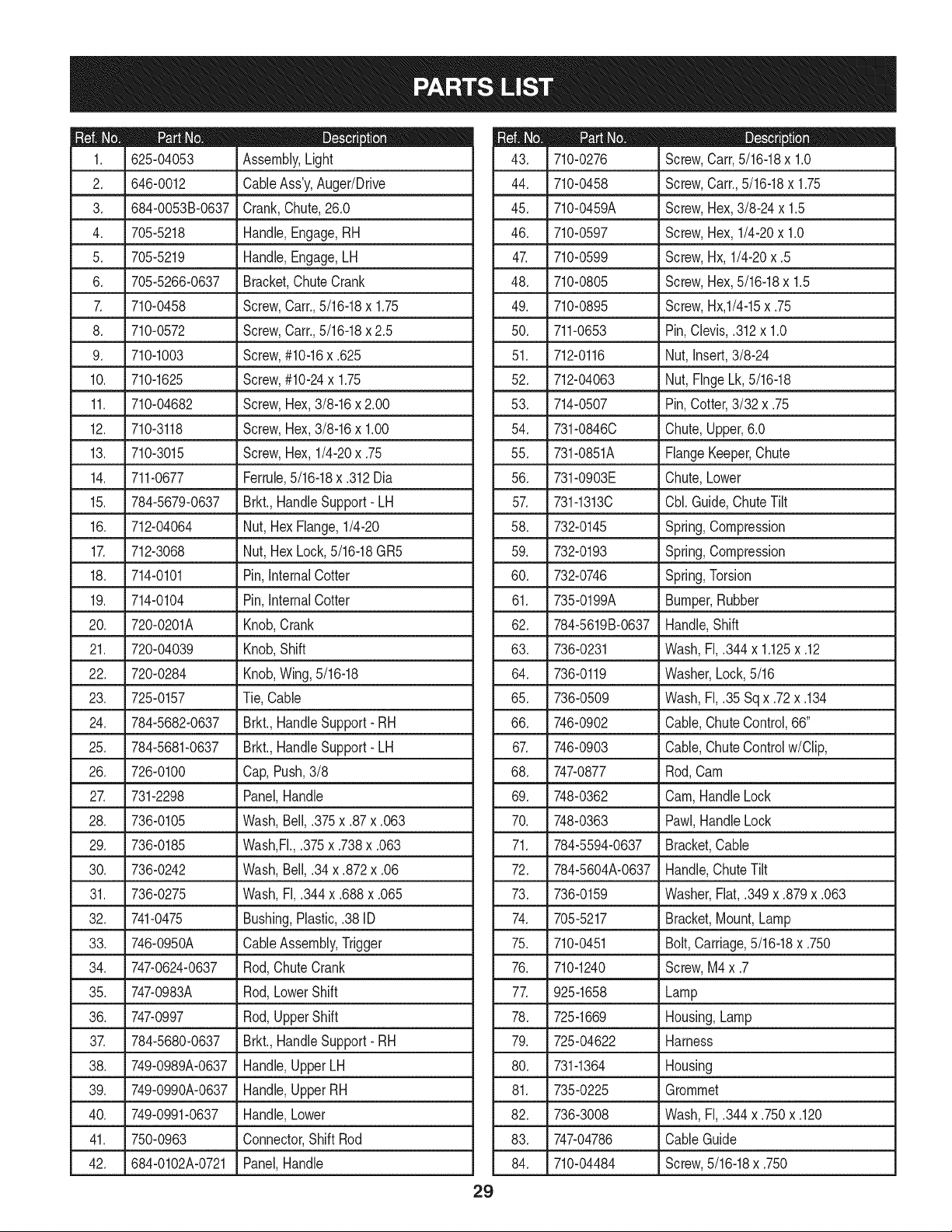
625-04053
2. _646-0012
3. 684-0053B-0637
4. 705-5218
5. 705-5219
6. 705-5266-0637
7. 710-0458
8. 710-0572
9. 710-1003
10. 710-1625
D _ O
Assembly,Light
CableAss'y,Auger/Drive
Crank,Chute,26.0
Handle,Engage,RH
Handle,Engage,LH
Bracket,ChuteCrank
Screw,Carr.,5/16-18x 1.75
Screw,Carr.,5/16-18x 2.5
Screw,#10-16x .625
Screw,#10-24x 1.75
11. 710-04682
12. 710-3118
13. 710-3015
14. 711-0677
15. 784-5679-0637
16. 712-04064
17. 712-3068
18. 714-0101
Screw,Hex,3/8-16x 2.00
Screw,Hex,3/8-16x 1.00
Screw,Hex, 1/4-20x .75
Ferrule,5/16-18x .312Dia
Brkt.,HandleSupport- LH
Nut, Hex Flange,1/4-20
Nut, Hex Lock,5/16-18GR5
Pin, InternalCotter
19. 714-0104 Pin, internalCotter
20. 720-0201A Knob,Crank
21. 720-04039 Knob,Shift
22. 720-0284 Knob,Wing,5/16-18
23. 725-0157 Tie, Cable
24. 784-5682-0637 Brkt., HandleSupport- RH
25. 784-5681-0637 Brkt., HandleSupport- LH
26. •7260100 Cap,Push,3/8
27. 731-2298 Panel,Handle
28. 736-0105 Wash,Bell,.375x .87 x .063
29. 736-0185 Wash,Fl.,.375x .738x .063
30. 736-0242 Wash,Bell,.34x .872x .06
31. 736-0275 Wash,FI,.344x .688x .065
32. 741-0475 Bushing,Plastic,.38ID
33. 746-0950A CableAssembly,Trigger
34. 747-0624-0637 Rod, ChuteCrank
35. 747-0983A
36. 747-0997
37. 784-5680 -0637
38. 749-0989A-0637
39. 749-0990A-0637
40. 749-0991-0637
41. 750-0963
42. 684-0102A-0721
Rod,LowerShift
Rod,UpperShift
Brkt.,HandleSupport- RH
Handle,UpperLH
Handle,UpperRH
Handle,Lower
Connector,Shift Rod
Panel,Handle
29
D _ W
710-0276 Screw,Carr,5/16-18x 1.0
44. 710-0458 Screw,Carr.,5/16-18x 1.75
45. 710-0459A Screw,Hex,3/8-24x 1.5
46. 710-0597 Screw,Hex,1/4-20x 1.0
47. 710-0599 Screw,Hx, 1/4-20x .5
48. 710-0805 Screw,Hex,5/16-18x 1.5
49. 710-0895 Screw,Hx,1/4-15x .75
50. 711-0653 Pin,Clevis,.312x 1.0
51. 712-0116 Nut,insert,3/8-24
52. 712-04063 Nut,FlngeLk,5/16-18
53. 714-0507 Pin,Cotter,3/32 x .75
54. 731-0846C Chute,Upper,6.0
55. 731-0851A FlangeKeeper,Chute
56. 731-0903E Chute,Lower
57. 731-1313C Cbl.Guide,ChuteTilt
58. 732-0145 Spring,Compression
59. 732-0193 Spring,Compression
60. 732-0746 Spring,Torsion
61. 735-0199A Bumper,Rubber
62. 784-5619B-0637 Handle,Shift
63. 736-0231 Wash,FI,.344 x 1.125x .12
64. 736-0119 Washer,Lock,5/16
65. 736-0509 Wash,FI,.35 Sq x .72x .134
66. 746-0902 Cable,ChuteControl,66"
67. 746-0903 Cable,ChuteControlw/Clip,
68. 747-0877 Rod,Cam
69. 748-0362 Cam, HandleLock
70. 748-0363 Pawl,HandleLock
71. 784-5594-0637 Bracket,Cable
72. 784-5604A-0637 Handle,ChuteTilt
73. 736-0159 Washer,Fiat,.349x .879x .063
74. 705-5217 Bracket,Mount,Lamp
75. 710-0451 Bolt,Carriage,5/16-18x .750
76. 710-1240 Screw,M4x .7
77. 925-1658 Lamp
78. 725-1669 Housing,Lamp
79. 725-04622 Harness
80. 731-1364 Housing
81. 735-0225 Grommet
82. 736-3008 Wash,FI,.344 x .750x .120
83. 747-04786 CableGuide
84. 710-04484 Screw,5/16-18x .750
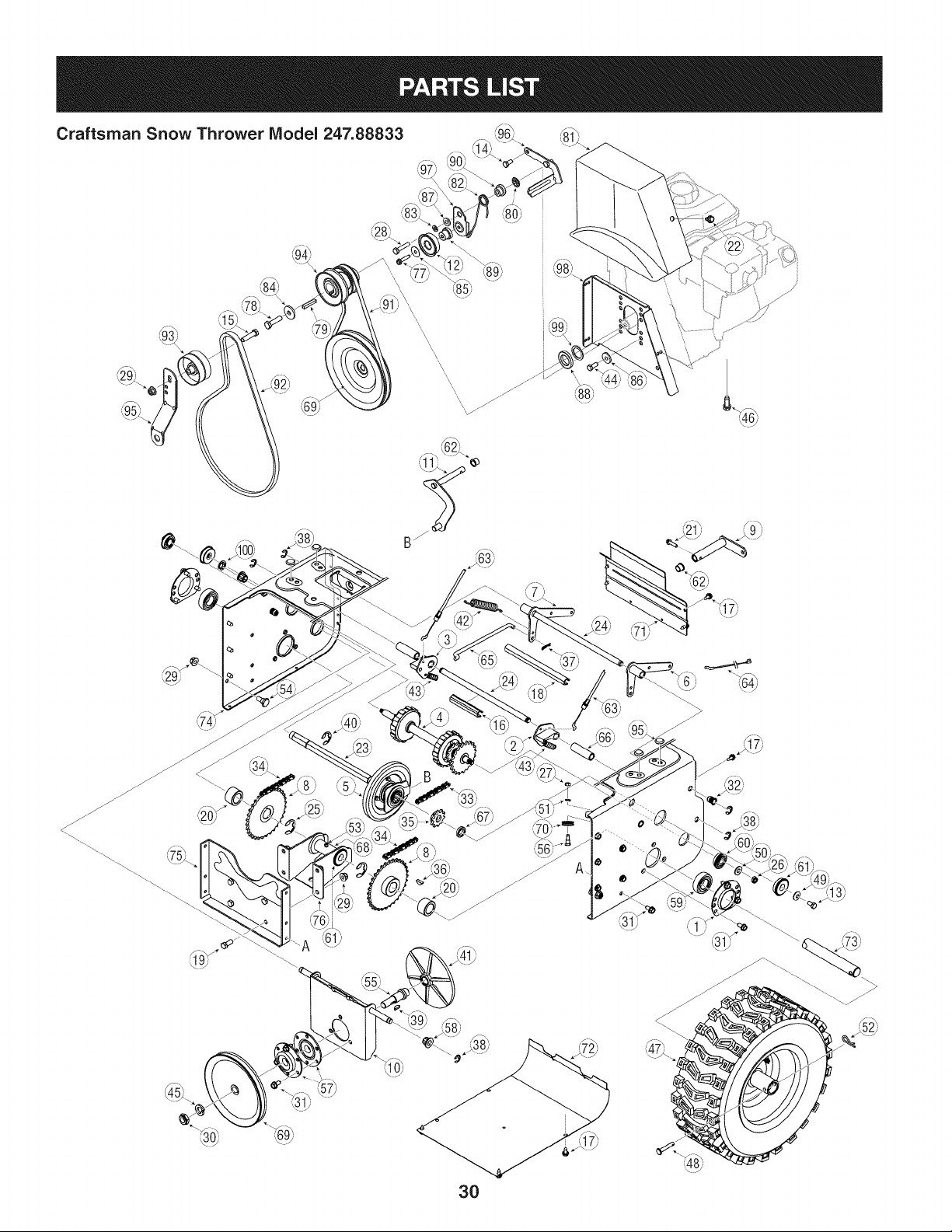
Craftsman Snow Thrower Model 247.88833 _6}... ,_i_
\
30
\\\ ,
\\
(527'
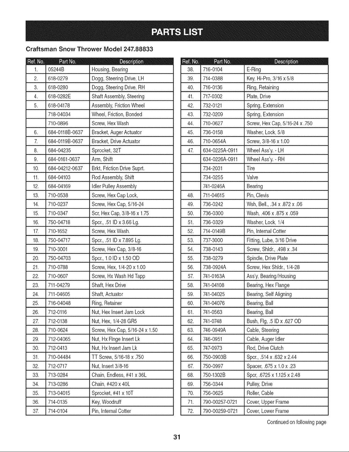
Craftsman Snow Thrower IViodel 247.88833
|= o o
05244B Housing,Bearing
2. 618-0279 Dogg,SteeringDrive,LH
3. 618-0280 Dogg,SteeringDrive,RH
4. 618-0282E ShaftAssembly,Steering
5. 618-04178 Assembly,FrictionWheel
718-04034 Wheel,Friction,Bonded
710-0896 Screw,HexWash
6. 684-0118B-0637 Bracket,AugerActuator
7. 684-0119B-0637 Bracket,DriveActuator
8. 684-04235 Sprocket,32T
9. 684-0161-0637 Arm,Shift
10. 684-04212-0637 Brkt, FrictionDriveSuprt.
11. 684-04103 RodAssembly,Shift
12. 684-04169 Idler PulleyAssembly
13. 710-0538 Screw,Hex CapLock,
14. 710-0237 Screw,Hex Cap,5/16-24
15. 710-0347 Scr, HexCap,3/8-16x 1.75
16. 750-04718 Spcr.,.51 ID x 3.66 Lg.
17. 710-1652 Screw,HexWash.
18. 750-04717 Spcr.,.51 ID x 7.895Lg.
19. 710-3001 Screw,Hex Cap,3/8-16
20. 750-04703 Spcr.,1.0IDx 1.50OD
21. 710-0788 Screw,Hex, 1/4-20x 1.00
22. 710-0607 Screw,HxWashHdlapp
23. 711-04279 Shaft,HexDrive
24. 711-04605 Shaft,Actuator
25. ,716-04048 _ Ring,Retainer
26. 712-0116 Nut, HexInsertJam Lock
27. 712-0138 Nut, Hex,1/4-28GR5
28. 710-0624 Screw,HexCap,5/16-24x 1.50
29. 712-04065 Nut, HxFlngeInsertLk
30. 712-0413 Nut, Hx InsertJam Lk
31. 710-04484 TT Screw,5/16-18x .750
32. 712-0717 Nut, Insert3/8-16
33. 713-0284 Chain,Endless,#41x 36L
34. 713-0286 Chain,#420x 40L
35. 713-04015 Sprocket,#41x lOT
36. 714-0135 Key,Woodruff
37. 714-0104 Pin,InternalCotter
D = " O O
716-0104 E-Ring
39. 714-0388 Key,Hi-Pro,3/16x 5/8
40. 716-0136 Ring,Retaining
41. 717-0302 Plate,Drive
42. 732-0121 Spring,Extension
43. 732-0209 Spring,Extension
44. 710-0627 Screw,HexCap,5/16-24x .750
45. 736-0158 Washer,Lock,5/8
46. 710-0654A Screw,3/8-16x 1.00
47. 634-0225A-0911 WheelAss'y.- LH
634-0226A-0911 WheelAss'y.- RH
734-2031 Tire
734-0255 Valve
741-0246A Bearing
48. 711-04615 Pin,Clevis
49. 736-0242 Wsh,Bell.,.34x .872x .06
50. 736-0300 Wash,.406x .875x .059
51. 736-0329 Washer,Lock,1/4
52. 714-0149B Pin,InternalCotter
53. 737-3000 Fitting,Lube,3/16 Drive
54. 738-0143 Screw,Shldr.,.498x .34
55. 738-0279 Spindle,DrivePlate
56. 738-0924A Screw,HexShldr.,1/4-28
57. 741-0163A Ass'y,Bearing/Housing
58. 741-04108 Bearing,HexFlange
59. 741-04025 Bearing,Self Aligning
60. 741-04076 Bearing,Ball
61. 741-0563 Bearing,Ball
62. 741-0748 Bush,Fig,.5 ID x .627OD
63. 746-0949A Cable,Steering
64. 746-0951 Cable,AugerIdler
65. 747-0973 Rod,DriveClutch
66. 750-0903B Spcr.,.514x .632x 2.44
67. 750-0997 Spacer,.675x 1.0x .23
68. 750-1302B Spcr,.6725x 1.125x 2.48
69. 756-0344 Pulley,Drive
70. 756-0625 Roller,Cable
71. 790-00257-0721 Cover,UpperFrame
72. 790-00259-0721 Cover,LowerFrame
Continuedonfollowingpage
31
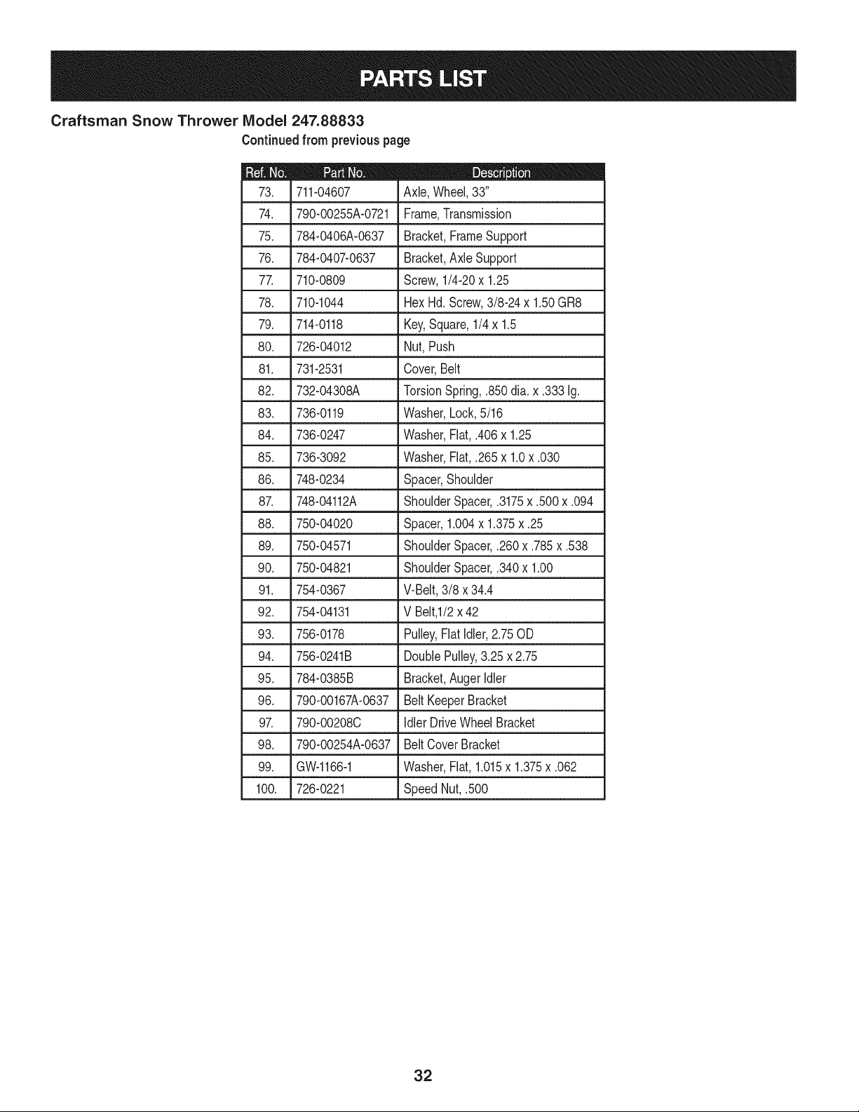
Craftsman Snow Thrower IViodel 247.88833
Continuedfrom previouspage
I = 0
711-04607 Axle, Wheel,33"
74. 790-00255A-0721 Frame,Transmission
75. 784-0406A-0637 Bracket,FrameSupport
76. 784-0407-0637 Bracket,Axle Support
77. 710-0809 Screw,1/4-20x 1.25
78. 710-1044 HexHd.Screw,3/8-24x 1.50GR8
79. 714-0118 Key,Square,1/4x 1.5
80. 726-04012 Nut,Push
81. 731-2531 Cover,Belt
82. 732-04308A TorsionSpring,.850dia.x .333Ig.
83. 736-0119 Washer,Lock,5/16
84. 736-0247 Washer,Flat,.406x 1.25
85. 736-3092 Washer,Flat,.265x 1.0x .030
86. 748-0234 Spacer,Shoulder
87. 748-04112A ShoulderSpacer,.3175x .500x .094
88. 750-04020 Spacer,1.004x 1.375x .25
89. 750-04571 ShoulderSpacer,.260x .785x .538
90. 750-04821 ShoulderSpacer,.340x 1.00
91. 754-0367 V-Belt,3/8 x 34.4
92. 754-04131 V Belt,l/2 x 42
93. 756-0178 Pulley,FlatIdler,2.75OD
94. 756-0241B DoublePulley,3.25 x 2.75
95. ,784-0385B Bracket, Augerldler
96. 790-00167A-0637 BeltKeeperBracket
97. 790-00208C IdlerDriveWheelBracket
98. 790-00254A-0637 BeltCoverBracket
99. GW-1166-1 Washer,Flat, 1.015x 1.375x .062
100. 726-0221 SpeedNut,.500
32
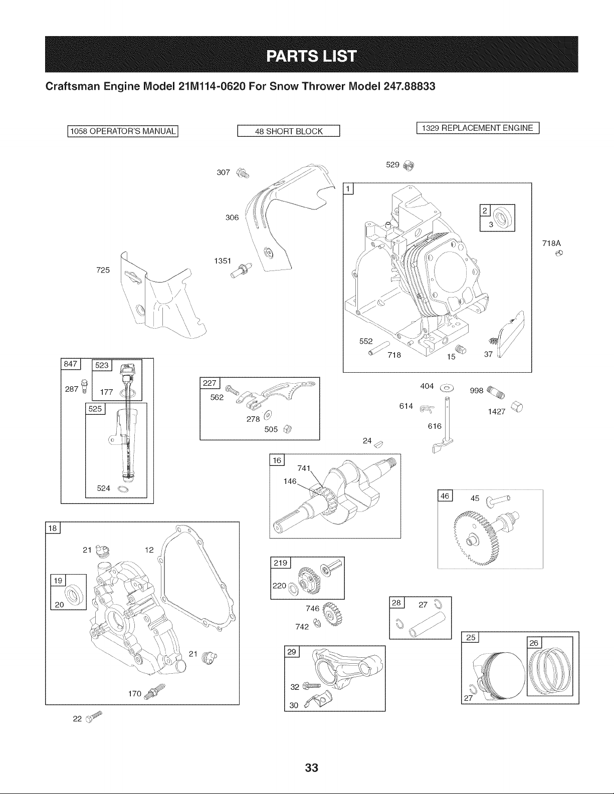
Craftsman Engine Model 211Vi114=0620 For Snow Thrower Model 247.88833
11058 OPERATOR'S MAN UAL I
[ 48 SHORT BLOCK I
I 1329 REPLACEMENT ENGINE I
725
,.>
84.7_ 523_ r_l_:_
287_177._
12
22
306
1351
24
741
746
742 %
2l
32 _c_ "_
529
718
404 (_)
614 (_,._,16 I1
718A
998
1427 _
33
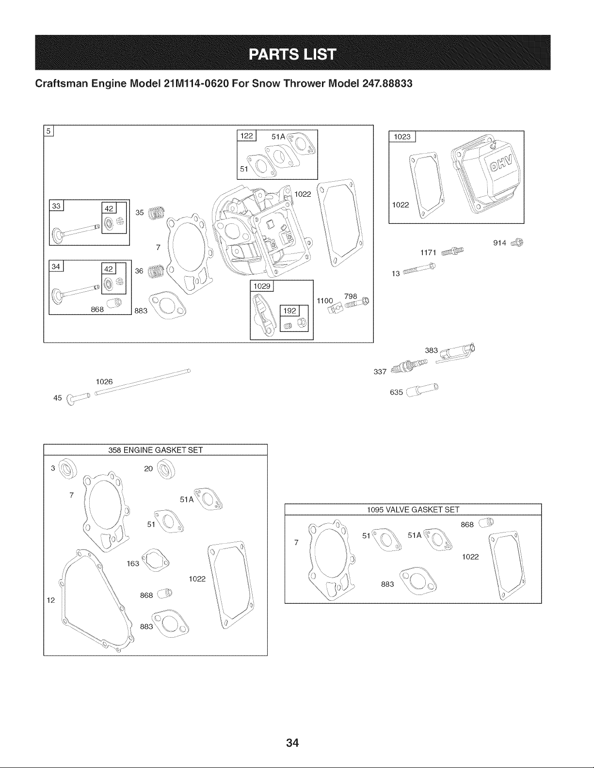
Craftsman Engine Model 211Vi114-0620 For Snow Thrower Model 247.88833
J
51 A {
[7S:::_::::::: :::::::::_
1022
.......... }:iiiii0
1026 ......:;:::::::::::::::::::::::...."
45 (,_}::::::X::c'
1o22
1171 _
13
914 _,_
383 _:_s" ,,cD
337 ('o-"_'_--q_"
635 ,,. ',b.......
12
358 ENGINE GASKET SET
20
1095 VALVE GASKET SET
868 t)_;
883
1o22
34
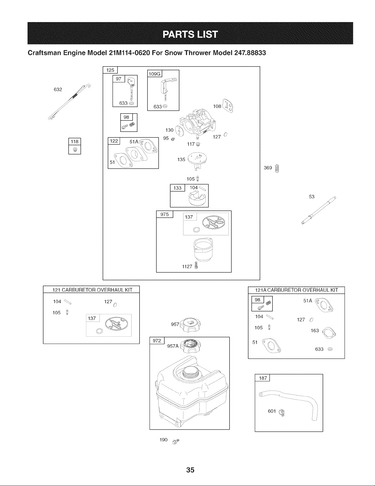
Craftsman Engine IViodel 211Vi114=0620 For Snow Thrower IViodel 247.88833
_9_J _!97
I 633 _!_',I
633 ,_-_" 108
130
95 @'
51A,', 117 @
127 O
135
lO50
| lO4%
1127
369 _
53
121 CARBURETOR OVERHAUL KIT
104 _
105
957A
121A CARBURETOR OVERHAUL KIT
51A
104 _ 127 0
105
163
51
633 _>_
_:: .............. (.. _ .....
"\\
19o _p
35
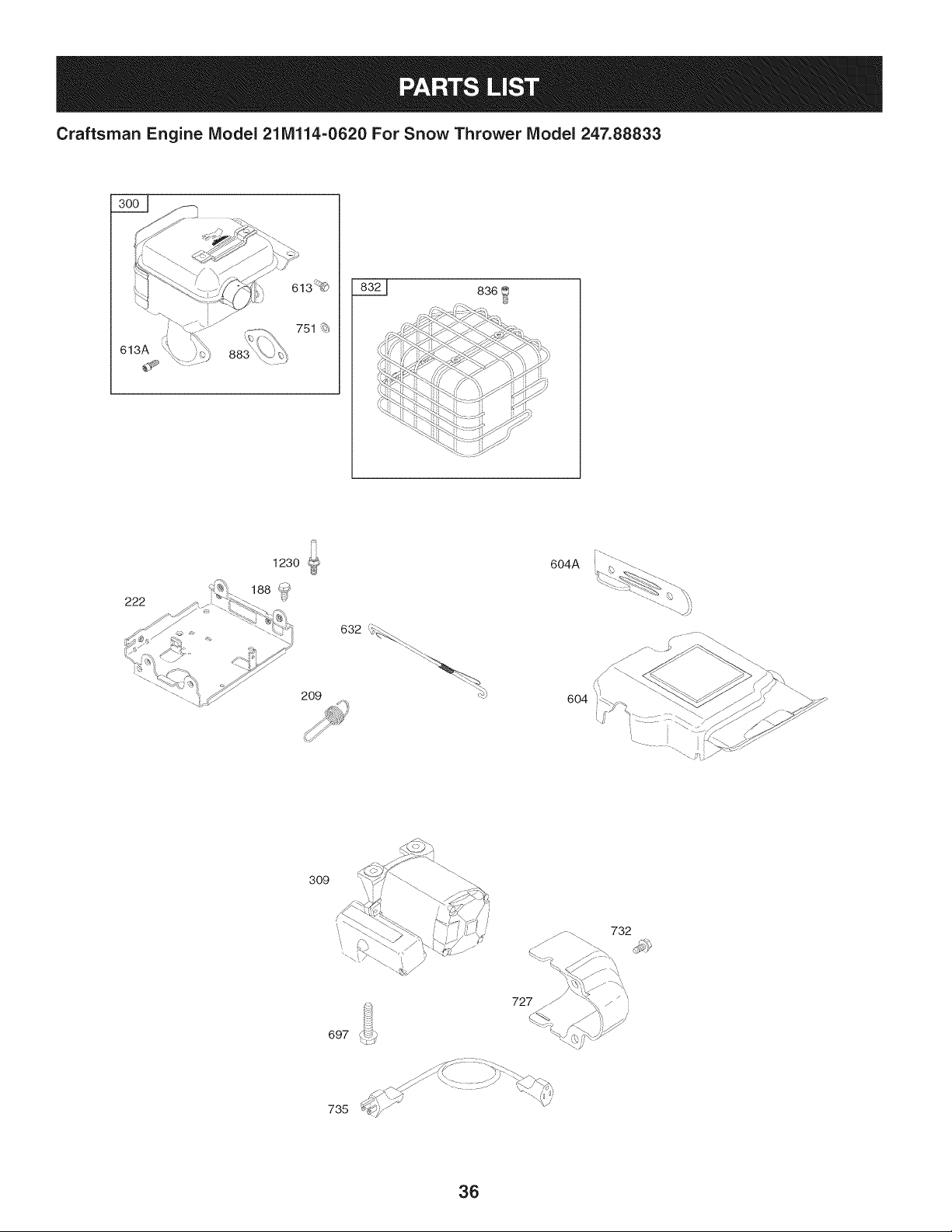
Craftsman Engine Model 211Vi114=0620 For Snow Thrower Model 247.88833
222
123o
188 _z
209
632 ','_....
c_j
604A
309
735
36
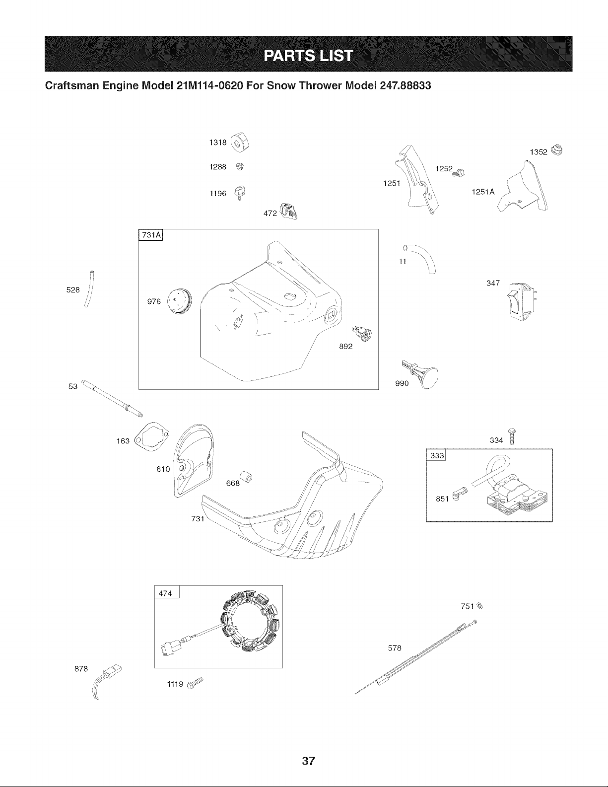
Craftsman Engine Model 211Vi114=0620 For Snow Thrower IViodel 247.88833
528
_!//'
1318 'I_),
1288
163
610
1251
i._d i 1251A
1196
d , /x
//
472 _ /
731
892
11
990
668 _
_,.)
!
851
1352/.X_, _,
347
878
751%
578
37
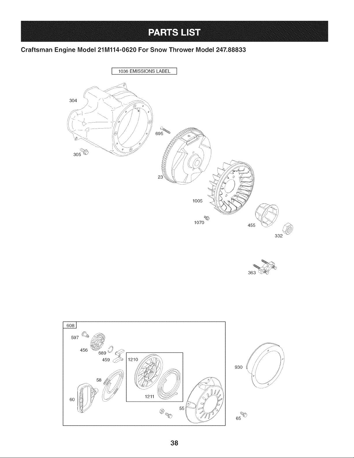
Craftsman Engine Model 211Vi114-0620 For Snow Thrower Model 247.88833
I 1036 EMISSIONS LABEL I
332
456 - 689
459
58
6O
121
1211
55
930
38
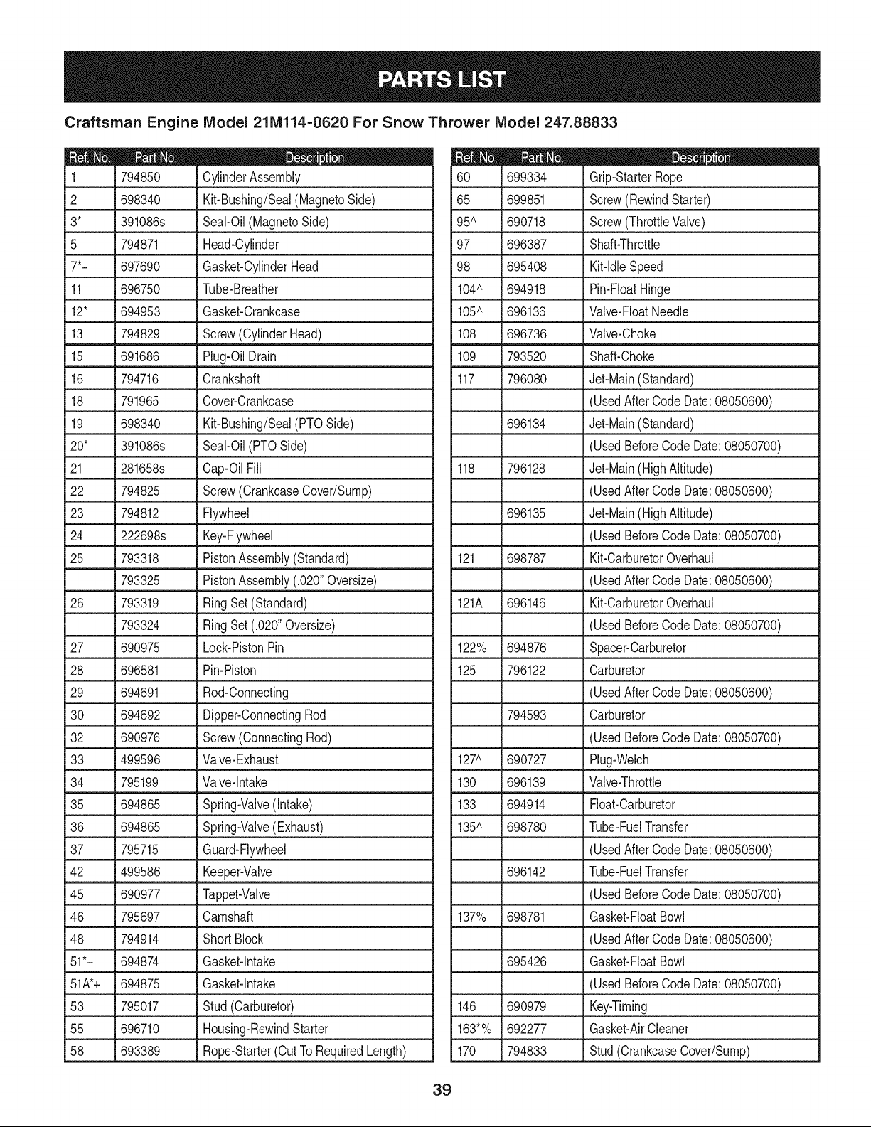
Craftsman Engine Model 211Vi114=0620 For Snow Thrower Model 247.88833
D = 0 0
794850 CylinderAssembly
2 698340 Kit-Bushing/Seal(MagnetoSide)
3* 391086s Seal-Oil(MagnetoSide)
5 794871 Head-Cylinder
7*+ 697690 Gasket-CylinderHead
11 696750 Tube-Breather
12" 694953 Gasket-Crankcase
13 794829 Screw(CylinderHead)
15 691686 Plug-OilDrain
16 794716 Crankshaft
18 791965 Cover-Crankcase
19 698340 Kit-Bushing/Seal(PTOSide)
20* 391086s Seal-Oil(PTO Side)
21 281658s Cap-OilFill
22 794825 Screw (CrankcaseCover/Sump)
23 794812 Flywheel
24 222698s Key-Flywheel
25 793318 PistonAssembly(Standard)
793325 PistonAssembly(.020"Oversize)
26 793319 RingSet(Standard)
793324 RingSet(.020"Oversize)
27 690975 Lock-PistonPin
28 696581 Pin-Piston
29 694691 Rod-Connecting
30 694692 Dipper-ConnectingRod
32 690976 Screw(ConnectingRod)
33 499596 Valve-Exhaust
34 795199 Valve-Intake
35 694865 Spring-Valve(Intake)
36 694865 Spring-Valve(Exhaust)
37 795715 Guard-Flywheel
42 499586 Keeper-Valve
45 690977 Tappet-Valve
46 795697 Camshaft
48 794914 Short Block
51"+ 694874 Gasket-Intake
51A*+ 694875 Gasket-Intake
53 795017 Stud (Carburetor)
55 696710 Housing-RewindStarter
58 693389 Rope-Starter(Cut To RequiredLength)
D = W
699334 Grip-StarterRope
65 699851 Screw(RewindStarter)
95^ 690718 Screw(ThrottleValve)
97 696387 Shaft-Throttle
98 695408 Kit-IdleSpeed
104^ 694918 Pin-FloatHinge
105^ 696136 Valve-FloatNeedle
108 696736 Valve-Choke
109 793520 Shaft-Choke
117 796080 Jet-Main(Standard)
(UsedAfterCodeDate:08050600)
696134 Jet-Main(Standard)
(UsedBeforeCodeDate:08050700)
118 796128 Jet-Main(HighAltitude)
(UsedAfterCodeDate:08050600)
696135 Jet-Main(HighAltitude)
(UsedBeforeCodeDate:08050700)
121 698787 Kit-CarburetorOverhaul
(UsedAfterCodeDate:08050600)
121A 696146 Kit-CarburetorOverhaul
(UsedBeforeCodeDate:08050700)
122% 694876 Spacer-Carburetor
125 796122 Carburetor
(UsedAfterCodeDate:08050600)
794593 Carburetor
(UsedBeforeCodeDate:08050700)
127^ 690727 Plug-Welch
130 696139 Valve-Throttle
133 694914 Float-Carburetor
135^ 698780 Tube-FuelTransfer
(UsedAfterCodeDate:08050600)
696142 Tube-FuelTransfer
(UsedBeforeCodeDate:08050700)
137% 698781 Gasket-FloatBowl
(UsedAfterCodeDate:08050600)
695426 Gasket-FloatBowl
(UsedBeforeCodeDate:08050700)
146 690979 Key-Timing
163*% 692277 Gasket-AirCleaner
170 794833 Stud(CrankcaseCover/Sump)
39

Craftsman Engine IViodel 211Vi114=0620 For Snow Thrower IViodel 247.88833
m = 0 0
795015 SeaI-ORing(Dipstick)
187 699479 Line-Fuel
188 691693 Screw(ControlBracket)
192 690083 Adjuster-RockerArm
209 695491 Spring-Governor
219 693578 Gear-Governor
220 691724 Washer(GovernorGear)
222 794801 Bracket-Control
227 694864 Lever-GovernorControl
232 691842 Spring-GovernorLink
238 691843 Cap-Valve
278 792008 Washer(GovernorControl Lever)
287 699269 Screw(DipstickTube)
300 794948 Muffler
304 795699 Housing-Blower
305 699480 Screw(BlowerHousing)
306 697240 Shield-Cylinder
307 794822 Screw(CylinderShield)
309 793524 Motor-Starter
332 794824 Nut(Flywheel)
333 492341 Armature-Magneto
334 699477 Screw(MagnetoArmature)
337 491055s Plug-Spark
347 698338 Switch-Rocker
358 795201 GasketSet-Engine
363 19203 Puller-Flywheel
369 695422 Spring-FloatBowl
(UsedBeforeCode Date:08050700)
383 19374s Wrench-SparkPlug
404 795759 Washer(GovernorCrank)
455 795011 Cup-Flywheel
456 692299 Plate-PawlFriction
459 281505s PawI-Ratchet
472 791948 Knob-ChokeShaft
474 793118 Alternator
505 691251 Nut(GovernorControlLever)
523 790477 Dipstick
524 691876 Seal-DipstickTube
525 792041 Tube-Dipstick
528 793006 Hose-Primer
529 791822 Grommet
D = O O
694674 Bushing-GovernorCrank
562 793216 Bolt(GovernorControlLever)
578 792576 WireAssembly
597 691696 Screw(PawlFrictionPlate)
601 791850 Hose-Clamp
604 696758 Cover-Control
604A 790473 Cover-Control
608 699335 Starter-Rewind
610 794541 Arrester-Intake
613 794846 Screw(Muffler)(Short)
613A 691678 Screw(Muffler)(Torx)
614 691620 Pin-Cotter(GovernorCrank)
616 795758 Crank-Governor
632 695917 Spring/Link-MechanicalGovernor
633 690998 Seal-Choke/ThrottleShaft
635 691909 Boot-SparkPlug
k
668 794539 Spacer(SnowHood)
689 691855 Spring-Friction
695 698807 Screw(RingGear)
697 795012 Screw(DriveCap)
718 690959 Pin-Locating(Cylinder)
718A 695178 Pin-Locating(CylinderHead)
725 696756 Shield-Heat
727 697465 Cover-StarterDrive
731 794540 Hood-Snow(Bottom)
731A 793621 Hood-Snow
732 699200 Screw(StarterDriveCover)
735 795901 Cord-Starter
741 691288 Gear-Timing
742 692564 Retainer-ERing
746 694679 Gear-Idler
751 794839 Washer(StopWire)
798 697890 Screw(RockerArm)
832 795078 Guard-Muffler
836 699234 Screw(MufflerGuard)
842 691031 SeaI-ORing(DipstickTube)
847 795087 Dipstick/TubeAssembly
851 692424 Terminal-SparkPlug
868*+ 794086 Seal-Valve
878 398661 Wire/Connector-Alternator
883*+ 695398 Gasket-Exhaust
4O
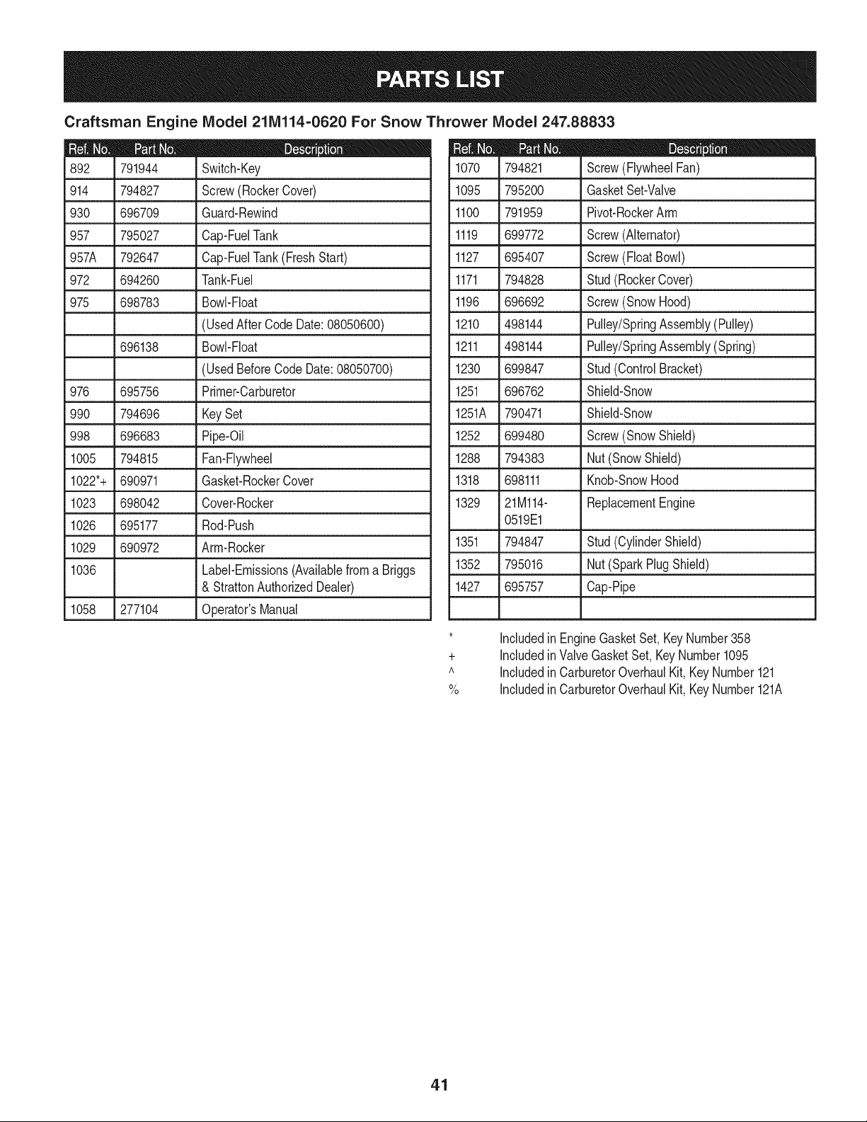
Craftsman Engine IViodel 211Vi114-0620 For Snow Thrower IViodel 247.88833
D = 0 0
791944 Switch-Key
914 794827 Screw(RockerCover)
930 696709 Guard-Rewind
957 795027 Cap-FuelTank
957A 792647 Cap-FuelTank(FreshStart)
972 694260 Tank-Fuel
975 698783 Bowl-Float
(UsedAfterCodeDate:08050600)
696138 Bowl-Float
(UsedBeforeCode Date:08050700)
976 695756 Primer-Carburetor
990 794696 KeySet
998 696683 Pipe-Oil
1005 794815 Fan-Flywheel
1022"+ 690971 Gasket-RockerCover
1023 698042 Cover-Rocker
1026 695177 Rod-Push
1029 690972 Arm-Rocker
1036 Label-Emissions(Availablefrom a Briggs
& StrattonAuthorizedDealer)
1058 277104 Operator'sManual
D= I O
794821 Screw(FlywheelFan)
1095 795200 GasketSet-Valve
11O0 791959 Pivot-RockerArm
1119 699772 Screw(Alternator)
1127 695407 Screw(FloatBowl)
1171 794828 Stud(RockerCover)
1196 696692 Screw(SnowHood)
1210 498144 Pulley/SpringAssembly(Pulley)
1211 498144 Pulley/SpringAssembly(Spring)
1230 699847 Stud(ControlBracket)
1251 696762 Shield-Snow
1251A 790471 Shield-Snow
1252 699480 Screw(SnowShield)
1288 794383 Nut(SnowShield)
1318 698111 Knob-SnowHood
1329 21Ml14- ReplacementEngine
0519E1
1351 794847 Stud(CylinderShield)
1352 795016 Nut(SparkPlugShield)
1427 695757 Cap-Pipe
+
A
%
Includedin EngineGasketSet, KeyNumber358
Includedin ValveGasketSet, KeyNumber1095
Includedin CarburetorOverhaulKit, Key Number121
Includedin CarburetorOverhaulKit, Key Number121A
41

42

43
(Thispageapplicableinthe U.S.A.and Canadaonly.)
Sears, Roebuck and Co., U.S.A. (Sears), the California Air Resources Board (CARD)
and the United States Environmental Protection Agency (U.S. EPA)
Emission Control System Warranty Statement (Owner's Defect Warranty Rights and Obligations)
EMISSIONCONTROLWARRANTYCOVERAGEISAPPLICABLETOCERTI-
FIEDENGINESPURCHASEDIN CALIFORNIAIN 1995ANDTHEREAF-
TER,WHICHARE USEDINCALIFORNIA,ANDTO CERTIFIEDMODEL
California and United States Emission
The CaliforniaAir ResourcesBoard(CARD),U.S.EPAand Searsare pleased
to explainthe EmissionControlSystemWarrantyon your modelyear2000and
latersmalloff-roadengine(SORE).In California,newsmall off-roadengines
mustbe designed,builtand equippedto meetthe State'sstringentanti-smog
standards.Elsewherein the UnitedStates, newnon-road,spark-ignition
enginescertifiedfor modelyear 1997and latermustmeetsimilarstandardsset
forth bythe U.S.EPA.Sears mustwarranttheemissioncontrol systemonyour
YEAR 1997AND LATERENGINESWHICHARE PURCHASEDAND USED
ELSEWHEREIN THE UNITEDSTATES(ANDAFTERJANUARY1,2001 IN
CANADA).
Control Defects Warranty Statement
enginefor theperiodsoftime listedbelow,providedtherehasbeen noabuse,
neglector impropermaintenanceof your smalloff-roadengine.Youremis-
sion controlsystemincludespartssuch as thecarburetor,air cleaner,ignition
system,mufflerand catalyticconverter.Also includedmaybe connectorsand
otheremissionrelatedassemblies.Wherea warrantableconditionexists,Sears
will repairyour smalloff-roadengineat no costto you includingdiagnosis,parts
and labor.
Sears Emission Control Defects Warranty Coverage
Smalloff-roadenginesarewarrantedrelativeto emissioncontrol partsdefects
fora periodof one year,subjectto provisionsset forth below.Ifany covered
Owner's Warranty
Asthe smalloff-roadengine owner,you are responsiblefor the performanceof
therequiredmaintenancelistedin yourOperatingand MaintenanceInstruc-
tions.Searsrecommendsthatyou retain all yourreceiptscoveringmaintenance
on yoursmalloff-roadengine,butSears cannotdenywarrantysolelyfor the
lackof receiptsor for yourfailureto ensuretheperformanceof all scheduled
maintenance.As the smalloff-roadengineowner,you shouldhoweverbe
awarethat Searsmay denyyou warrantycoverageif your smalloff-roadengine
ora part hasfailed dueto abuse,neglect,impropermaintenanceor unap-
parton yourengineis defective,the part willbe repairedor replacedbySears.
Responsibilities
provedmodifications.Youare responsiblefor presentingyour smalloff-road
engineto an AuthorizedSearsServiceDealeras soonas a problemexists.The
undisputedwarrantyrepairsshouldbe completedina reasonableamountof
time,not to exceed30 days.Ifyou haveany questionsregardingyourwarranty
rightsand responsibilities,you shouldcontacta SearsService Representative
at 1-800-469-4663.The emissionwarrantyis a defectswarranty.Defectsare
judgedon normalengineperformance.Thewarrantyis notrelatedto an in-use
emissiontest.
Sears Emission Control Defects Warranty Provisions
ThefollowingarespecificprovisionsrelativetoyourEmissionControlDefectsWarrantyCoverage.ItisinadditiontotheSearsenginewarrantyfornon-regulated
enginesfound in the Operatingand MaintenanceInstructions.
1. WarrantedParts
Coverageunderthis warrantyextendsonly to the parts listedbelow (the
emissioncontrolsystemsparts)to the extentthese partswere presenton
theenginepurchased.
a. FueIMeteringSystem
• Cold start enrichmentsystem
• Carburetorand internalparts
• FuelPump
b. Air lnduction System
• Air cleaner
• Intakemanifold
c. IgnitionSystem
• Spark plug(s)
• Magnetoignitionsystem
d. CatalystSystem
• Catalyticconverter
• Exhaustmanifold
• Air injectionsystemor pulsevalve
e. MiscellaneousItemsUsedin AboveSystems
• Vacuum,temperature,position,timesensitivevalves
andswitches
• Connectorsandassemblies
2. Lengthof Coverage
Searswarrantsto the initialownerand eachsubsequentpurchaserthat
theWarrantedPartsshallbe free from defects in materialsandworkman-
shipwhich causedthe failure of the WarrantedPartsfor a periodof one
yearfrom the datethe engineis deliveredto a retailpurchaser.
3. NoCharge
Repairor replacementof anyWarrantedPartwill be performedat no
chargeto the owner,includingdiagnosticlabor whichleads to the
determinationthata WarrantedPartis defective,ifthe diagnosticwork is
performedat an AuthorizedSears ServiceDealer.For emissionswarranty
servicecontact yournearestAuthorizedSearsServiceDealeras listed in
the "YellowPages"under"Engines,Gasoline,""GasolineEngines,""Lawn
Mowers,"orsimilarcategory.
4. Claimsand CoverageExclusions
Warrantyclaimsshall be filed in accordancewiththe provisionsof the
Sears EngineWarrantyPolicy.Warrantycoverageshall be excludedfor
failuresof WarrantedPartswhichare not original Sears partsor because
of abuse,neglector impropermaintenanceas setforth inthe Sears
EngineWarrantyPolicy.Sears is not liableto coverfailuresof Warranted
Partscausedby theuseof add-on,non-original,or modifiedparts.
5. Maintenance
Any WarrantedPart whichis notscheduledfor replacementas required
maintenanceor whichis scheduledonly for regularinspectionto the effect
of "repairor replaceas necessary"shallbe warrantedas to defectsfor the
warrantyperiod.Any WarrantedPartwhich is scheduledfor replacement
as requiredmaintenanceshallbe warrantedas to defectsonly forthe
periodof time upto the first scheduledreplacementfor that part. Any
replacementpart that is equivalentin performanceand durabilitymay
be usedin the performanceof any maintenanceor repairs.The owneris
responsibleforthe performanceof all requiredmaintenance,as definedin
the SearsOperatingand MaintenanceInstructions.
6. ConsequentialCoverage
Coveragehereundershallextend to the failure of any engine components
caused bythe failureof any WarrantedPartstill underwarranty.
Inthe USAandCanada,a 24 hourhotline, 1-800-469-4663,has a menu of pre-recordedmessagesofferingyou enginemaintenanceinformation.
GDOC-100188Rev.A
44
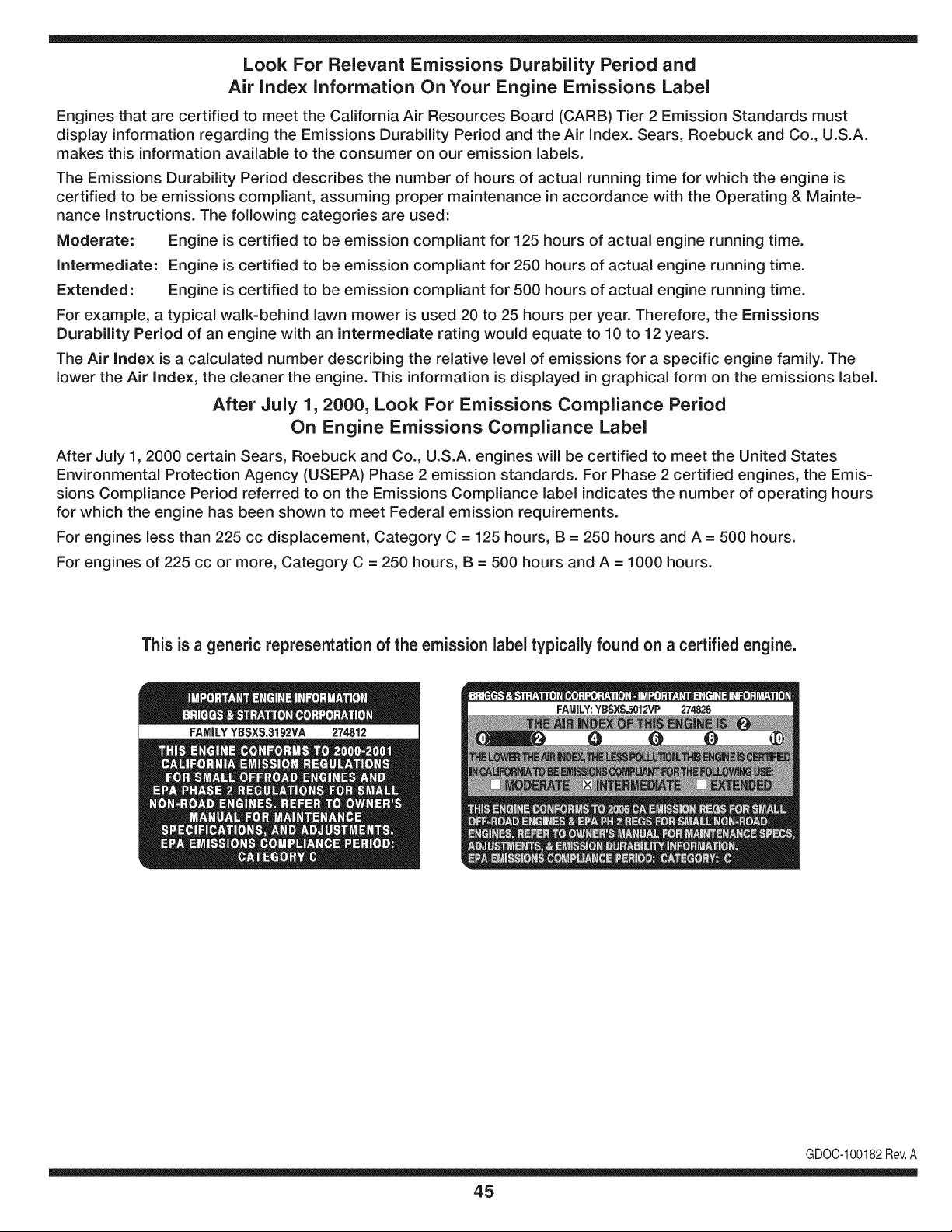
Look For Relevant Emissions Durability Period and
Air index information On Your Engine Emissions Label
Engines that are certified to meet the California Air Resources Board (CARB) Tier 2 Emission Standards must
display information regarding the Emissions Durability Period and the Air Index. Sears, Roebuck and Co., U.S.A.
makes this information available to the consumer on our emission labels.
The Emissions Durability Period describes the number of hours of actual running time for which the engine is
certified to be emissions compliant, assuming proper maintenance in accordance with the Operating & Mainte-
nance Instructions. The following categories are used:
Moderate: Engine is certified to be emission compliant for 125 hours of actual engine running time.
Intermediate: Engine is certified to be emission compliant for 250 hours of actual engine running time.
Extended: Engine is certified to be emission compliant for 500 hours of actual engine running time.
For example, a typical walk-behind lawn mower is used 20 to 25 hours per year. Therefore, the Emissions
Durability Period of an engine with an intermediate rating would equate to 10 to 12 years.
The Air Index is a calculated number describing the relative level of emissions for a specific engine family. The
lower the Air Index, the cleaner the engine. This information is displayed in graphical form on the emissions label.
After July 1,2000, Look For Emissions Compliance Period
On Engine Emissions Compliance Label
After July 1, 2000 certain Sears, Roebuck and Co., U.S.A. engines will be certified to meet the United States
Environmental Protection Agency (USEPA) Phase 2 emission standards. For Phase 2 certified engines, the Emis-
sions Compliance Period referred to on the Emissions Compliance label indicates the number of operating hours
for which the engine has been shown to meet Federal emission requirements.
For engines less than 225 cc displacement, Category C = 125 hours, B = 250 hours and A = 500 hours.
For engines of 225 cc or more, Category C = 250 hours, B = 500 hours and A = 1000 hours.
This is a generic representation of the emission label typically found on a certified engine.
FAMILYYBSXS.3192VA 274812
GDOC-100182Rev.A
45
Congratulationson makinga smartpurchase.YournewCraftsman@
productis designedand manufacturedfor yearsof dependableopera-
tion.But likeall products,it may requirerepairfrom time to time.That's
whenhavinga RepairProtectionAgreementcansave youmoneyand
aggravation.
Here'swhatthe RepairProtectionAgreement*includes:
* Expert service byour 10,000professionalrepairspecialists
o Unlimitedserviceand no chargefor partsand laboron all
coveredrepairs
o Product replacementupto $1500if yourcoveredproductcan't be
fixed
• Discountof 10%from regularprice of serviceand relatedinstalled
partsnotcoveredby theagreement;also, 10%off regularpriceof
preventivemaintenancecheck
• Fast help by phone- we call it RapidResolution- phone support
froma Searsrepresentative.Thinkof usas a "talkingowner's
manual."
Onceyou purchasethe Agreement,a simplephonecall is all that it
takesfor youto scheduleservice.Youcan call anytimedayor night,or
schedulea serviceappointmentonline.
The RepairProtectionAgreementis a risk-freepurchase.If youcancel
for any reasonduringthe productwarrantyperiod,wewill providea full
refund.Or,a proratedrefundanytimeafterthe productwarrantyperiod
expires.Purchaseyour RepairProtectionAgreementtoday!
Somelimitationsand exclusionsapply. For pricesand additional
informationin the U.S.A. call 1-800-827-6655.
*Coverage in Canadavaries on some items.Forfull details call
Sears Canadaat 1-800-361-6665.
Sears Installation Service
ForSearsprofessionalinstallationof homeappliances,garagedoor
openers,waterheaters,and othermajorhomeitems,in the U.S.A.or
Canadacall 1-800-4-MY-HOME®.
46
Declaraci6n de garantia ............................ Pagina 47
Practicas operaci6n seguras ..................... Pagina 48
Montaje ...................................................... Pagina 50
Operaci6n .................................................. Pagina 54
Servicio y Mantenimiento .......................... Pagina 58
Almacenamiento fuera de temporada ....... Pagina 67
Soluci6n de problemas .............................. Pagina 68
Etiquetas de seguridad .............................. Pagina 7
Lista de piezas ........................................... Pagina 26
Acuerdo de protecci6n para reparaciones .... Pagina 71
NOmero de servicio ................................... atras pagina
CRAFTSMAN GARANTIA LIMITADA
Dos A_os en Lanzador de Nieve
Cuandohechofuncionary mantenidosegOntodaslas instruccionessuministradas,si estelanzadorde nieve falla debidoa un defecto en materialo habilidad
dentrode dos a_os de lafechao compra,1-800-4-MY-HOMEde Ilamada® para hacer losarreglospara la reparaci6nlibre.
Esta garanfiasolicitas61ouna5ode lafecha de la comprasi este lanzadorde nieve es usadoalgunavez para objetivosde alquilero publicidad.
Duranteel primera_o de lacompra,no habr_ningOnpreciopara el servicio de garanfia en su casa. Parasuconveniencia,en de casa el serviciode garanfia
todav[aestarAdisponibledespuesdel primera5ode la compra,pero un precio de viaje seaplicarA. Esteprecio serArenunciadosi ustedtransporta al lanzador
de nieve a un autorizadoCraftsmanposici6nde bajada.Para la posici6nautorizadamAscercana,call 1-800-4-MY-HOME®.
Esta garanfiacubre SOLOdefectosen materialy habilidad.Chamuscano pagarApara:
• Los arficulos prescindiblesque se hacenIlevadospuestosduranteel uso normal,incluso,perono limitadospara patinarzapatos,platode afeitado,
esquilanalfileres,buj[a,filtro de aire,cinturones,yfiltro del aceite.
• Revisi6nde mantenimientoest_ndar,cambiosde aceite, o puestasa punto.
• Reemplazode neum_ticoo reparaci6ncausadapor pinchazosdesdefuerade objetos,como u_as,espinas,tocones,o cristal.
• Neumaticoo reemplazoderueda o reparaci6nque resultade ropa normal,accidente,u operaci6n impropiao mantenimiento.
• Las reparacionesnecesariasdebido al abusode operador,incluso pero no limitadopara da_arcausadoafectandoobjetosquedoblan el marcoo el
cigQe_al,o el sobreexcesode velocidaddel motor.
• Reparacionesnecesariasdebidoa negligenciadeoperador,incluso perono limitadocon,da_o el@tricoy mecanicocausadoporalmacenaje
impropio,fracasode usarel gradoapropiadoy cantidadde petr61eode motor,o fracasode mantenerelequiposegQnlasinstruccionescontenidas
en el manualdel operador.
• Motor(sistemade combustible)la limpiezao las reparacionescausadasporel combustibledeterminaronde set contaminadasu oxidado(se
vuelven duro). Engeneral, el combustibledeberiaser usado30 diasdespuesde su fecha de compra.
• El empejoramientonormaly la ropa de los finesexteriores,o productoetiquetanel reemplazo.
Esta garantiase aplica s61omientraseste productoes dentrode los EstadosUnidos.
Esta garantiale da derechos legalesespecificos,y ustedtambienpuedetenet otros derechosque varian de estado alestado.
Sears, Roebuck and Co., Hoffman Estates, IL 60179
Tipode aceitedelmotor:
Capacidadde aceitedel motor:
Capacidadde combustible:
Bujias:
Separaci6nde las bujias:
SAE5W-30
28onzas
4cuartos
Champion@RC12YC
.030"
NSmerode modelo ..........................................................
N_mero de serie ..............................................................
Fechade compra .............................................................
Registrearribael nOmerodel modelo,el nOmerode seriey la fecha
de compra
© Sears Brands,LLC
47
La presenciade estesfmboloindica que setrata de
instruccionesimportantesde seguridad quese deben
respetarpara evitar poneren peligrosu seguridad
personaly/o materialy lade otras personas.Leay siga
todas las instruccionesde este manualantesde poner
en funcionamientoesta m&quina.Si norespetaestas instruccionespodrfa
provocarlesionespersonales.Cuandovea este sfmbolo,ipresteatenci6na
laadvertencia!
Suresponsabilidad:Restrinjael usode esta rn_.quinarnotorizada
alas personasque lean,cornprendany respetenlas advertenciase
instruccionesqueapareceneneste manualy en la rn_.quina.
Esta m_quinafue construidaparaset operadadeacuerdocon las reglas
de seguridadcontenidasen este manual.AI igualque con cualquiertipo
de equipo motorizado,un descuidoo error por partedel operadorpuede
producirlesionesgraves.Esta m_quinaes capazdeamputarmanosy pies
y dearrojarobjetoscon gran fuerza.De no respetarlasinstruccionesde
seguridadsiguientesse puedenproducirlesionesgraveso la muerte.
Elescape del motorde este producto,algunosdesus componentesy
algunoscomponentesdel vehfculocontieneno liberan sustanciasqufmicas
queel estado de Californiaconsideraquepueden producirc_ncer,defectos
de nacimientou otrosproblemasreproductivos.
CAPAClTACl6N
• Lea,entienday cumplatodas las instruccionesincluidasen la m_quina
yen los manualesantesde montarlay utilizarla.Guardeeste manual
en un lugarseguroparaconsultasfuturasy regulates,asf como para
solicitarrepuestos.
• Familiarfcesecon todos loscontrolesy sufuncionamientoapropiado.
Sepac6mo detenerla m_quinay c6mo desengranarlos controles
r_pidamente.
• No permitanuncaque losni_os menoresde 14a6os utilicenesta
m_quina.Los ni_os de 14a_osy m_smayoresdeben leery com-
prenderlas instruccionesde funcionamientoy lasreglas de seguridad
contenidasen este manual,y tambiendebenset capacitadosy estar
supervisadospor unode los padres.
• Nuncapermitaquelos adultosutilicen esta m_quinasin recibir antesla
instrucci6napropiada.
• Los objetosarrojadosporla m_quinapuedenproducirlesionesgraves.
Planifiqueel patr6nen el queva air arrojandonievepara evitarque la
descargade materialse realicehacia los caminos,losobservadores,
etc.
• Mantengaa losobservadores,ayudantes,mascotasy ni_os por Io
menosa 75 piesde la m_quinamientrasla mismaest_ en funciona-
miento.Detengala m_quinasi alguien entraen lazona.
• Seaprecavidopara evitarpatinarseo caerseespecialmentecuando
operala m_quinaen reversa.
PREPARATIVOS
• Inspeccioneminuciosamenteel _readondeutilizar_el equipo.Saque
todoslosfelpudos,peri6dicos,trineos,tablas,cablesy otrosobjetos
extra_oscon los que podrfatropezaro quepodrfanset arrojadospot la
barrena/ motor.
• Paraprotegerselosojos utilice siempreanteojoso antiparrasde
seguridadmientrasopera lam_quinao mientrasla ajustao repara.Los
objetosarrojadosque rebotanpuedenlesionargravementelavista.
• No operela m_quinasinla vestimentaadecuada paraestar al aire libre
en invierno.No utilicealhajas,bufandaslargasu otras prendassueltas
que podrfanenredarseen laspartesm6viles.Utiliceun calzadoespecial
para superficiesresbaladizas.
• Use un prolongadory untomacorrientede tres cablesconconexi6na
tierra paratodas las unidadescon motoresde encendidoelectrico.
• Ajustela altura de la caja del tomacorrientepara limpiarla gravao las
superficiesconpiedrastrituradas.
• Desengranetodas las palancasde controlantes de arrancarel motor.
• Nuncaintenterealizarajustesmientrasel motorest_en marchaexcepto
en loscasos especfficamenterecomendadosen el manualdel operador.
• Deje queel motory la m_quinaseadaptena latemperaturaexterior
antes de comenzara sacar la nieve.
• Paraevitarlesionespersonalesoda_osmaterialesseasumamentecuidadosoal
manipularlagasdina.Lagaselinaesaltamenteinflamableysusvaporespuedencauser
expbsiones.Sepuedelesionargravementesiderramagasdinasobreustedosebrela
ropayaquesepuedeprenderfuego.Laveselapielyo_mbiesederopadeinmediato.
• Utilice s61orecipientespara gasolinaautorizados.
• Apaguetodosloscigarrillos,cigarros,pipasyotrasfuentesde combusti6n.
• Nuncacarguecombustibleen la m&quinaen un espaciocerrado.
• Nuncasaque latapa del gas ni agreguecombustiblemientrasel motor
est& calienteo en marcha.
• Deje queel motorse enfrfepot Io menosdos minutosantesde volvera
cargar combustible.
• Nuncarecargueeltanque de combustible.Llene eltanque no m_sde
1/2pulgadapor debajode la basedel cuellodel filtro para dejar espacio
para la dilataci6ndel combustible.
• Vuelvaa colocar la tapa de lagasolinay ajQstelabien.
• Limpie lagasolinaderramadasobre el motory el equipo.Trasladela
m_quinaa otra zona. Espere5 minutosantes de encenderel motor.
• Nuncaalmacenela m_quinao el recipientede combustibleen un
espaciocerrado dondehayafuego,chispaso luzpiloto(porejemplo,
hornos,calentadoresde agua,calefactores,secadoresde ropa,etc.).
• Deje quela m_quinase enfrfepot Io menos5 minutosantes de
guardarla.
48
OPERACION
• No pongalas manoso lospies cercade las piezas rotatorias,en la caja
de la barrena/ motoro en el montajedel canalde descarga.Elcontacto
con las piezasrotatoriaspuedeproducirla amputaci6nde manosy pies.
• La palanca de control de la barrena/ motores un dispositivode seguri-
dad. Nuncapase poralto su funcionamiento.De hacerlola operaci6nde
la m&quinaes riesgosay puedeocasionarlesiones.
• Las palancasde controldebenfuncionarbienen ambasdireccionesy
regresarautom_ticamentea laposici6nde desengranecuandose las
suelta.
• Nuncaoperelam&quinasifaltaunmontajedelcanalo siel mismoest&daSado.
Mantengatodoslosdispositivosdeseguridaden sulugaryen funcionamiento.
• Nuncaenciendaun motoren espacioscerradoso en unazonacon poca
ventilaci6n.Elescapedel motorcontienemon6xidode carbono,ungas
inodoroy letal.
• No utilicela m_quinabajola influenciadel alcoholo lasdrogas.
• Elsilenciadory el motorse calientany puedenproducirquemaduras.No
lostoque.
• Seasumamenteprecavidocuandoopere la m_quinasobre una
superficiecongravao cuandola cruce. Mantengasealertapotsi se
presentanpeligrosocultoso tr_nsito.
• Tengacuidado cuandocambiede direcci6n o cuandoopere la m_quina
en pendientes.
• Planifiqueel patr6nen el queva a ir arrojandonieveparaevitar que
la descargade materialse produzcahacia lasventanas,las paredes,
losautom6viles,etc. y evitaras[ posiblesdaSosmaterialeso lesiones
producidaspor losrebotes.
• Nuncadirija ladescargahacialosniSos,los observadoresy las
mascotasni deje que nadiese pare delantedela m_quina.
• Nosobrecarguela capacidadde la m_quinatratandode sacarla nieve
muyr@idamente.
• Nuncaopereesta m_quinasin buenavisibilidado iluminaci6n.Siempre
debe estarsegurode queest&bienafirmado y sostengabien las
manijas.Camine,nuncacorra.
• Corte lacorrientea la barrena/ motorcuandotransportela m_quinao
cuandola mismano est_en uso.
• Nuncaoperela m_quinaa alta velocidadde desplazamientosobre
superficiesresbaladizas.Mirehacia abajoy haciaarrasy tenga cuidado
cuandovayamarchaatr&s.
• Si la m&quinacomenzaraa vibrar de maneraanormal,detengael motor,
desconecteel cablede la buj[ay p6ngalade maneraque hagamasa
contrael motor.Inspeccionela m_quinaminuciosamentepara ver si
est&daSada.Reparetodos losdaSosantes de encendery operarla
m&quina.
• Desengranetodas las palancasde control y detengael motorantesde
dejar la posici6nde operaci6n(detr&sde lasmanijas). Esperea que la
barrena/ motorse detengapor completoantesde destaparel montaje
del canalo realizarajustese inspecciones.
• Nuncapongalasmanosen las aberturasde descargao de recolecci6n.
Utilicesiemprela herramientade limpiezaque seadjuntapara destapar
la aberturade descarga.Nodestapeel montajedel canal mientrasel
motorest_en funcionamiento.Antesde destaparlo,apagueel motory
permanezcadetr_sdelas manijashastaquetodas las partesm6vilesse
hayandetenido.
• Uses61ounionesy accesoriosaprobadospot el fabricante (porejemplo,
pesaspara las ruedas,cadenasparalos neum&ticos,cabinas,etc.).
• Si se presentansituacionesque no est&nprevistasen este manual,sea
cuidadosoy useel sentidocomQn.Contactecon su centrode servicio
Sears paraobtenerayuda.
MANTENIMIENTO Y ALIVIACENANIIENTO
• Nuncamanipulelosdispositivosde seguridadde maneraimprudente.
Controleperi6dicamentequefuncionen de formaadecuada.Rem[tasea
lasseccionesde mantenimientoy ajustede estemanual.
• Antesde realizarlalimpieza,repararo revisar la m_quina,desengrane
todas laspalancasde controly detengael motor.Esperea que labar-
rena/ motorsedetenga porcompleto.Desconecteel cable dela buj[a
y p6ngalode manera quehaga masacontrael motorpara evitarque se
enciendade maneraaccidental.
• Controlefrecuentementequetodos los pernosy tornillosesten bien
ajustadosparacomprobarque la m&quinase encuentraen condiciones
segurasde funcionamiento.Asimismo,realiceuna inspecci6nvisual de
lam_quinapara controlarsi la mismaest&daSada.
• Nocambiela configuraci6ndel reguladordel motorni acelerede-
masiadoel mismo.El reguladorcontrolalavelocidad m_ximasegurade
operaci6ndel motor.
• Lasplacasde raspadoylaszapatasantideslizantesqueseusanconlamaquina
quitanievesedesgastany sedaSan.Paraprotegersuseguridad,verifique
frecuentementetodosloscomponentesyreempl&celoss61oconpartesde los
fabricantesdeequiposoriginales(OEM)."Lautilizaci6ndepiezasquenocum-
planconlasespecificacionesdeequiposoriginalespodr[atenetcomoresultado
unrendimientoincorrecto,y adem_slaseguridadpodr[aestarcomprometida"
• Reviselos controlesperi6dicamentepara verificarque engraneny
desengranenadecuadamentey ajL]stelossi es necesario.Consultela
secci6nde ajustesen este manualdel operadorparaobtenerinstruc-
clones.
• Mantengao reemplacelas etiquetasde seguridade instruccionessegQn
sea necesario.
• Respetelas normasreferentesa ladisposici6ncorrectay las reglamen-
tacionessobre gas, combustible,etc. para protegerel medioambiente.
• Antesde almacenarla m&quinaenciendalaunosminutosparasacar la
nieveque hayaquedadoen la mismay paraevitaras[ quese congelela
barrena/ motor.
• Nuncaalmacenela m_quinao el recipientede combustibleen un
espaciocerrado dondehayafuego,chispaso luz pilotocomopor
ejemplo,calentadoresde agua, hornos,secadoresde ropa,etc.
• Consultesiempreel manualde funcionamientoparaconocerlas instruc-
clonesadecuadasparael almacenamientofuerade temporada.
No modifique el motor
Paraevitar lesionesgraveso la muerte,no modifiqueelmotorbajoninguna
circunstancia.Si cambialaconfiguraci6ndel reguladorel motorpuededescon-
trolarsey operara velocidadesinseguras.Nuncacambielaconfiguraci6nde
f_bricadel reguladordel motor.
49
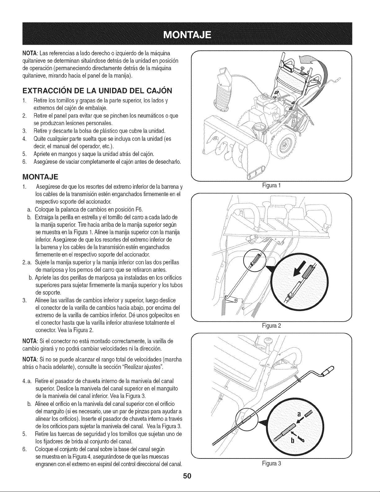
NOTA:Lasreferenciasa lado derechoo izquierdodela rn_.quina
quitanievesedeterrninansitu_.ndosedetr_.sdela unidaden posici6n
deoperaci6n(perrnaneciendodirectarnentedetr_.sdela rn_.quina
quitanieve,rnirandohaciael panelde la rnanija).
EXTRACCI6N DE LA UNIDAD DEL CAJON
1. Retirelos tornillosy grapasdela partesuperior,los ladosy
extrernosdel caj6n deernbalaje.
2. Retireel panelparaevitarque se pinchenlos neurn_.ticoso que
se produzcanlesionespersonales.
3. Retirey descartelabolsa de pl_.sticoquecubre la unidad.
4. Quitecualquierpartesueltaque se incluyacon la unidad(es
decir,el manualdel operador,etc.).
5. Aprieteen mangosy saquela unidadatr_.sdelcaj6n.
6. AsegQresede vaciarcornpletarnenteelcaj6nantesdedesecharlo.
NIONTAJE
1. Aseg_resede que losresortesdelextrernoinferiorde labarrenay
loscablesde la transrnisi6nest_nenganchadosfirrnernenteenel
respectivosoportedelaccionador.
a. Coloquela palancadecarnbiosenposici6nF6.
b. Extraigala perillaen estrellay el tornillodel carroa cadaladode
la rnanijasuperior.Tirehaciaarribade larnanijasuperiorsegQn
se rnuestraen la Figura1.Alineela rnanijasuperiorconla rnanija
inferior.AsegOresedequelos resortesdelextrernoinferiorde
la barrenay loscablesde la transrnisi6nestenenganchados
firrnernenteenel respectivosoportedel accionador.
2.a. Sujetelarnanijasuperiory larnanijainferiorcon lasdos perillas
de rnariposay los pernosdel carroquese retiraronantes.
b. Aprietelas dos periNasde rnariposaya instaladasen los orificios
superioresparasujetarfirrnernentela rnanijasuperiory los tubos
de soporte.
3. Alineelas varillasdecarnbiosinferiory superior,luegodeslice
el conectorde la variNadecarnbioshaciaabajo,por encirnadel
extrernode la varillade carnbiosinferior.De unosgolpecitosen
el conectorhastaquela variNainferioratraviesetotalrnenteel
conector.Veala Figura2.
NOTA:Si el conectornoest,.rnontadocorrectarnente,la varillade
carnbiogirard,y no podr_,carnbiarvelocidadesni la direcci6n.
NOTA:Si no se puedealcanzarel rangototalde velocidades(rnarcha
atr_.so haciaadelante),consultela secci6n"Realizarajustes".
4.a. Retireel pasadorde chavetainternode larnaniveladel canal
superior.Deslicela rnaniveladel canalsuperiorenel rnanguito
de larnaniveladel canalinferior.Vea la Figura3.
b. Alineeel orificioen la rnaniveladel canalsuperiorconel orificio
delrnanguito(si es necesario,useun par depinzasparaayudara
alinearlos orificios).Inserteel pasadordechavetainternoa traves
delosorificiosparasujetarlarnaniveladel canal. Veala Figura3.
5. Retirelas tuercasde seguridady los tornillosque sujetanunode
los fijadoresde bridaal conjuntodelcanal.
6. Coloqueel conjuntodelcanalsobrela basedelcanalsegQn
sernuestraenlaFigura4,asegur_.ndosedequelasrnuescas
engranenconel extrernoen espiraldelcontroldireccionaldelcanal.
f
f i 1
Figura1
J
f
Figura2
7/
J
Figura3
5O
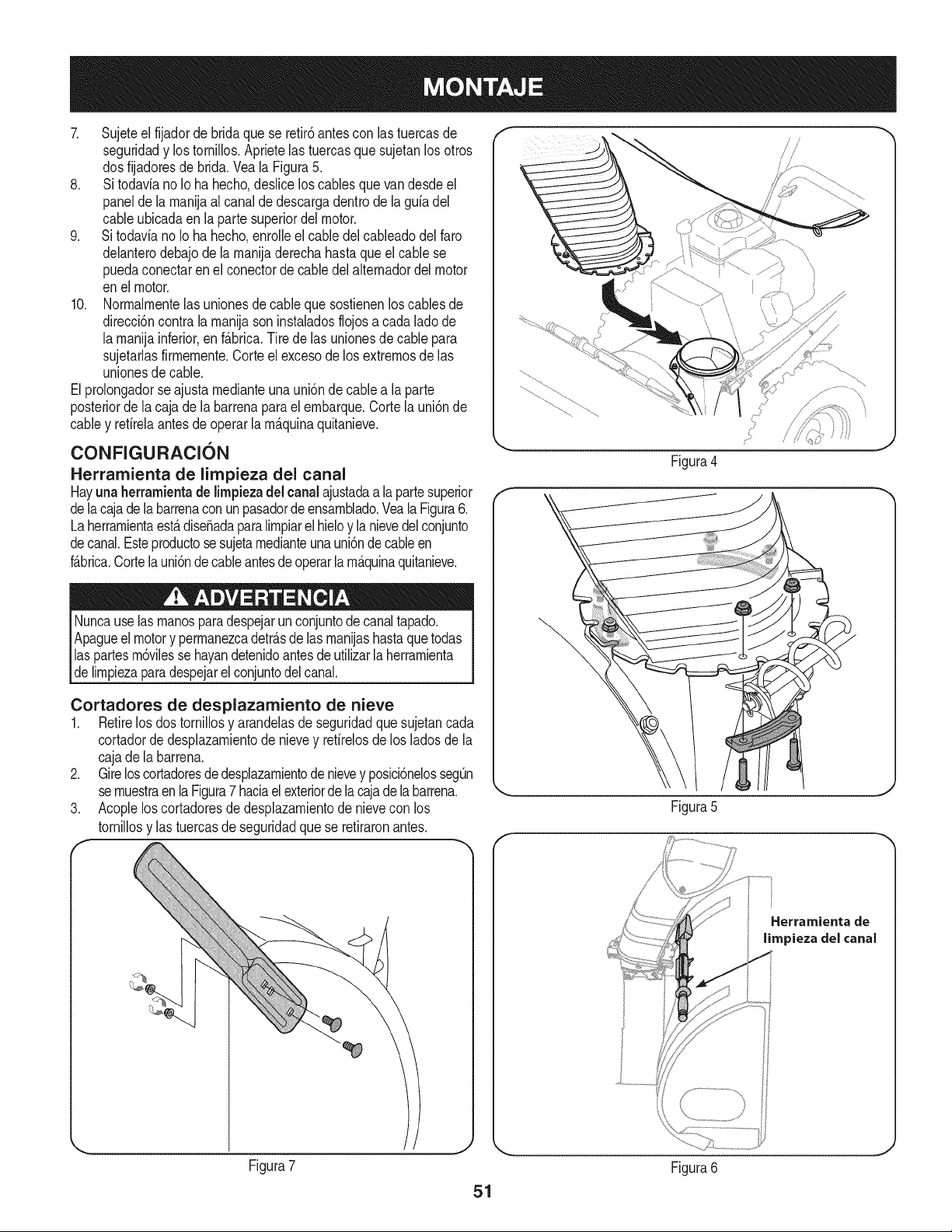
7. Sujeteel fijadorde bridaquese retir6antescon las tuercasde
seguridady los tornillos.Aprietelas tuercasque sujetanlos otros
dosfijadoresde brida.Veala Figura5.
8. SitodavianoIo ha hecho,deslice loscablesque van desdeel
panelde la rnanijaal canaldedescargadentrode la guiadel
cableubicadaen la partesuperiordel motor.
9. Si todavia no Io hahecho,enrolleel cabledel cableadodel faro
delanterodebajo de la rnanijaderechahastaque el cablese
puedaconectaren elconectordecabledelalternadordel motor
enel motor.
10. Norrnalrnentelas unionesdecableque sostienenlos cablesde
direcci6ncontrala rnanijason instabdosflojosa cadalado de
la rnanijainferior,en f_.brica.Tire de las unionesde cablepara
sujetarlasfirmernente.Corte el excesode los extrernosde las
unionesdecable.
Elprolongadorse ajustarnedianteunauni6n de cablea la parte
posteriorde la caja de la barrenaparael ernbarque.Cortela uni6nde
cabley refirelaantesde operarla rn_.quinaquitanieve.
CONFIGURACION
Herramienta de lirnpieza del canal
Hayuna herramientadelimpiezadelcanalajustadaa lapartesuperior
delacajadelabarrenaconunpasadorde ensarnblado.VealaFigura6.
Laherrarnientaest,.diseBadaparalirnpiarelhieloy la nievedel conjunto
decanal.Esteproductosesujetarnedianteuna uni6nde cableen
f_.brica.Cortelauni6ndecableantesdeoperarlarn_.quinaquitanieve.
Nuncauselas rnanosparadespejarunconjuntodecanaltapado.
Apagueel motory perrnanezcadetrAsde las rnanijashastaque todas
laspartesrn6vilesse hayandetenidoantesde utilizarla herrarnienta
jde rnpezaparadespejare conjuntode cana.
Cortadores de desplazamiento de nieve
1. Retirelos dostornillosy arandelasde seguridadque sujetancada
cortadordedesplazarnientodenievey refirelosde los ladosde la
cajade la barrena.
2. Gireloscortadoresdedesplazarnientode nievey posici6nelossegQn
sernuestraenlaFigura7 haciaelexteriorde lacajade la barrena.
3. Acopleloscortadoresde desplazarnientodenievecon los
tornillosy las tuercasde seguridadque se retiraronantes.
f
?
Figura4
Figura5
J
J
f
Herrarnienta de
lirnpieza del canal
Figura7
51
Figura6
J
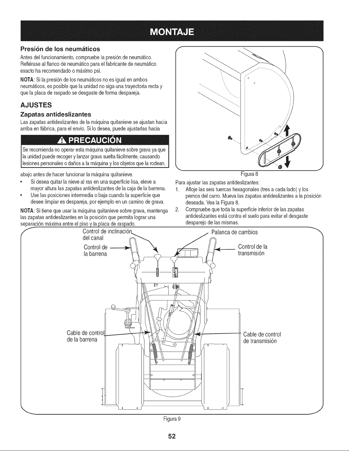
Presi6n de los neumaticos
Antesdelfuncionarniento,cornpruebelapresi6ndeneurn_.tico.
Refi@aseal fiancode neurn_.ticoparael fabricantede neurn_.tico
exactoha recornendadoo rn_.xirnopsi.
NOTA:Si la presi6nde los neurn_.ticosnoes igualenarnbos
neurn_.ticos,es posiblequela unidadno siga unatrayectoriarectay
que laplacade raspadose desgastede forrnadespareja.
AJUSTES
Zapatas antideslizantes
Laszapatasantideslizantesde la rn_.quinaquitanievese ajustanhacia
arribaenf_.brica,paraelenvio.Si Iodesea,puedeajustarlashacia
Se recorniendano operaresta rn_.quinaquitanievesobregravayaque
la unidadpuederecogery lanzargravasueltaf_.cilrnente,causando
esonespersonaes o da_osa a rn_.quna y os objetosque a rodean.
abajoantesde hacerfuncionarla rn_.quinaquitanieve.
• Si deseaquitarla nieveal ras en una superficielisa,elevea
mayoraltura laszapatasantideslizantesde la caja de la barrena.
• Use lasposicionesinterrnediao bajacuandola superficieque
deseelirnpiares despareja,por ejernploen uncarninodegrava.
NOTA:Si tieneque usarla rn_.quinaquitanievesobregrava,rnantenga
laszapatasantideslizantesen la posici6nque perrnitaIograruna
separaci6nrn_.xirnaentre el #!so _ Japlacade raspado.
f Control de
del canal
f
\
Figura8
Paraajustarlas zapatasantideslizantes:
1. Aflojelas seis tuercashexagonales(tresa cada lado)y los
pernosdel carro. Muevalas zapatasantideslizantesa la posici6n
deseada.Veala Figura8.
2. Cornpruebequetoda la superficieinferiorde las zapatas
antideslizantesest,.contrael suelopara evitarel desgaste
desparejode lasrnisrnas.
Control de
la barrena
Cable de control
de la barrena
Palanca de cambios
_LJ
Control de la
transmisi6n
Cable de control
de transmisi6n
FJgura9
J
52
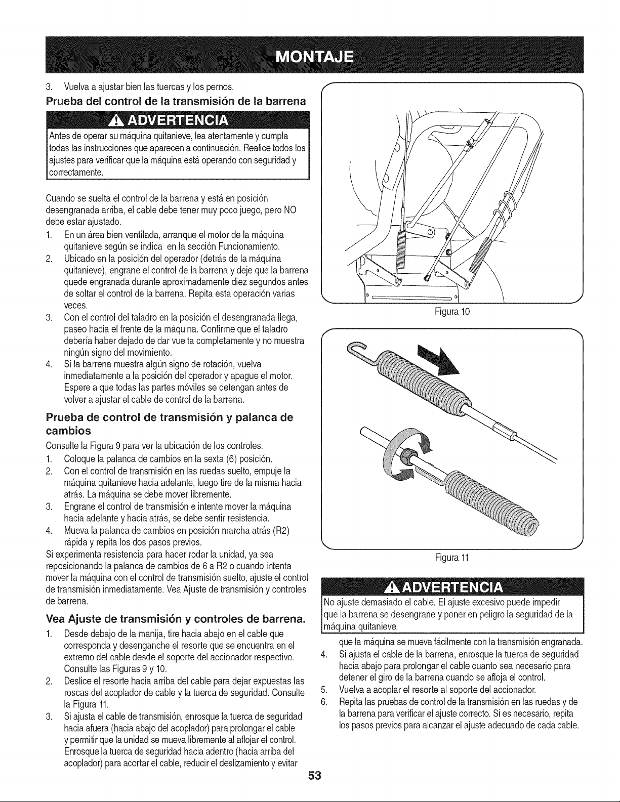
3. Vuelvaa ajustarbienlas tuercasy los pernos, f "_
Prueba del control de la transrnisi6n de la barrena
!
Antesdeoperarsum&quinaquitanieve,lea atentamentey cumpla
todaslas instruccionesqueaparecena continuaci6n.Realicetodoslos
Iajustesparaverificarque la m&quinaest&operandocon seguridady
[correctamente.
Cuandose sueltael controlde la barrenay est,.en posici6n
desengranadaarriba,elcabledebetenetmuypocojuego,peroNO
debeestarajustado.
1. Enun_.reabien ventilada,arranqueel motorde la m_.quina
quitanievesegQnse indica en la secci6nFuncionamiento.
2. Ubicadoen la posici6ndeloperador(detr_.sde la m_.quina
quitanieve),engraneel controlde la barrenay dejequela barrena
quedeengranadaduranteaproximadamentediez segundosantes
desoltarelcontroldela barrena.Repitaesta operaci6nvarias
veces.
3. Conel controldeltaladroen laposici6nel desengranadaIlega,
paseohada elfrentedela m&quina.Confirmeque el taladro
deberiahaberdejadodedarvueltacompletamentey nomuestra
ningQnsignodel movimiento.
4. Si labarrenamuestraalgQnsignode rotaci6n,vuelva
inmediatamentea laposici6ndel operadory apagueel motor.
Esperea que todas las partesm6vilesse detenganantesde
volvera ajustarelcablede controlde labarrena.
Prueba de control de transmisi6n y palanca de
cambios
Consultela Figura9 paraverla ubicaci6nde los controles.
1. Coloquela palancade cambiosen la sexta(6) posici6n.
2. Conel controldetransmisi6nen las ruedassuelto,empujela
m_.quinaquitanievehaciaadelante,luegotire de lamismahacia
atr_.s.Lam_.quinase debe moverlibremente.
3. Engraneel controlde transmisi6ne intentemoverla m_.quina
haciaadelantey haciaatr_.s,se debesentirresistencia.
4. Muevala palancade cambiosen posici6nmarchaatr_.s(R2)
r_.piday repitalos dospasos previos.
Siexperimentaresistenciapara hacerrodar la unidad,ya sea
reposicionandolapalancade cambiosde 6 a R2o cuandointenta
moverla m_.quinacon el controldetransmisi6nsuelto,ajusteel control
detransmisi6ninmediatamente.VeaAjuste de transmisi6ny controles
debarrena.
Vea Ajuste de transmisi6n y controles de barren&
1. Desdedebajode la manija,tire haciaabajoen el cableque
corresponday desengancheel resortequese encuentraenel
extremodelcabledesdeel soportedelaccionadorrespectivo.
Consultelas Figuras9 y 10.
2. Desliceel resortehaciaarriba del cablepara dejar expuestaslas
roscasdel acopladorde cabley la tuerca de seguridad.Consulte
la Figura11.
3. Si ajustael cablede transmisi6n,enrosquela tuercade seguridad
haciaafuera(haciaabajodelacoplador)paraprolongarel cable
y permitirque la unidadsemuevalibrementeal aflojarel control.
Enrosquela tuercade seguridadhaciaadentro(haciaarribadel
acoplador)paraacortarelcable,reducireldeslizamientoy evitar
Figura10
Figura11
J
Noajustedemasiadoel cable.El ajusteexcesivopuede impedir
que labarrenase desengraney ponerenpeligrola seguridadde la
m_.quinaquitanieve.
quela m_.quinasemuevaf_.cilmenteconla transmisi6nengranada.
4. Si ajustael cablede la barrena,enrosquela tuercade seguridad
haciaabajoparaprolongarel cablecuantosea necesariopara
detenerel giro de la barrenacuandoseafloja elcontrol.
5. Vuelvaa acoplarel resorteal soportedel accionador.
6. Repitalaspruebasde controlde latransmisi6nen lasruedasy de
labarrenaparaverificarel ajustecorrecto.Si esnecesario,repita
lospasospreviosparaalcanzarel ajusteadecuadodecadacable.
53
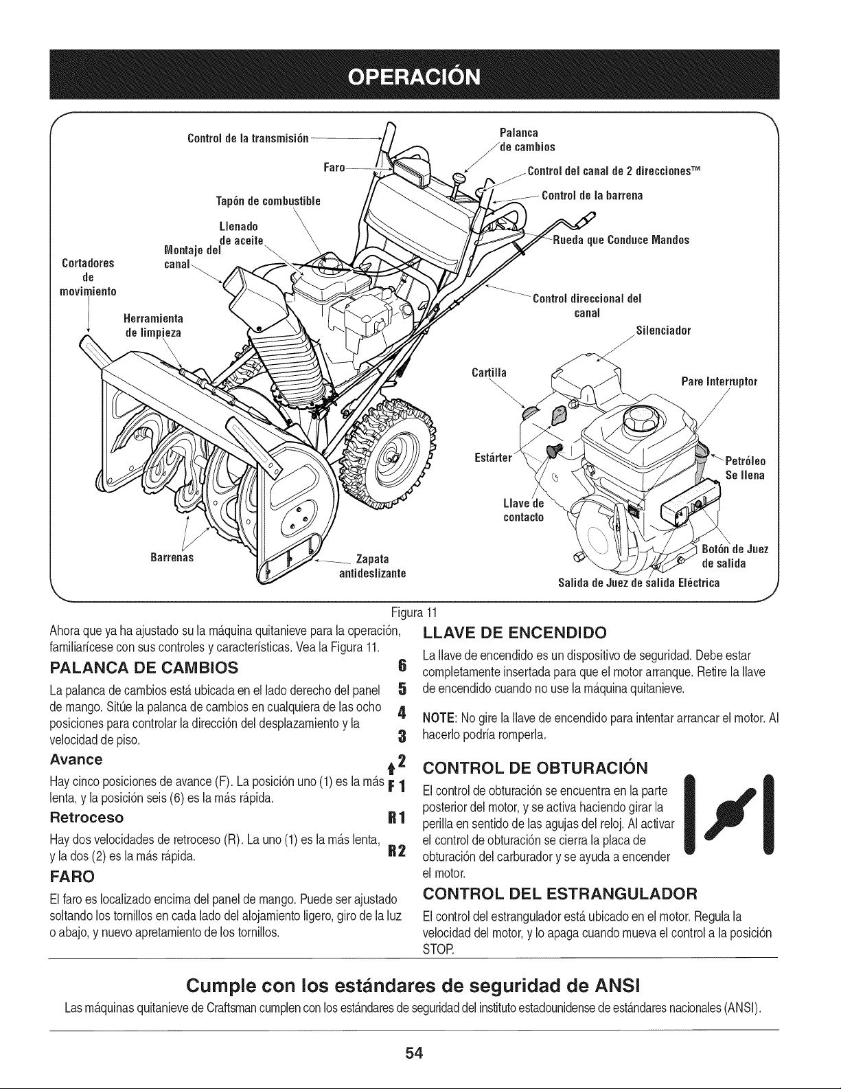
f
Cortadores
de
movimiento
Controldela transmisi6n
Tap6nde combustible
Llenado
deaceite
IVlontajedel \.
Herramienta
de limpieza
7apata
antidesiizante
Cartiiia
"\
\
\
Est_rter_
Llave'
contacto
Salida de Juezde
Figura11
Ahoraqueya ha ajustadosu la rn_.quinaquitanieveparala operaci6n,
farniliaricesecon suscontrolesy caracteristicas.Vea la Figura11.
PALANCA DE CAIVlBIOS
La palancade carnbiosest,. ubicadaen el ladoderechodel panel
de mango.SitQela palancade carnbiosen cualquierade las ocho
posicionesparacontrolarladirecci6ndeldesplazarnientoy la
velocidadde piso. 3
Avarice t 2
Haycincoposicionesde avance(F). La posici6nuno(1) es la rn_.sF 1
lenta,y la posici6nseis(6) es la rn_.sr_.pida.
Retroceso R 1
Haydosvelocidadesde retroceso(R). Launo(1)es la rn_.slenta,
y la dos (2) es la rn_.sr_.pida. R2
FARO
Elfaro es Iocalizadoencirnadelpaneldemango.Puedeser ajustado
soltandolostornillosen cadaladodelalojarnientoligero,giro de la luz
oabajo,y nuevoapretarnientode los tornillos.
LLAVE DE ENCENDIDO
,J
LaIlavedeencendidoes un dispositivode seguridad.Debeestar
6 cornpletarnenteinsertadaparaqueel motorarranque.Retirela Ilave
5 de encendidocuandono usela rn_.quinaquitanieve.
4
NOTE: Nogire la Ilavedeencendidopara intentararrancarel motor.AI
hacerlopodria rornperla.
CONTROL DE OBTURACION
Elcontroldeobturaci6nse encuentraen la parte
posteriordelmotor,y seactiva haciendogirarla
perillaensentidode lasagujasdel reloj.AI activar
el controldeobturaci6nse cierrala placade
obturaci6ndelcarburadory se ayudaa encender
el motor.
CONTROL DEL ESTRANGULADOR
Elcontroldelestranguladorest,.ubicadoen el motor.Regulala
velocidaddelmotor,y Ioapagacuandornuevael controla la posici6n
STOR
Cumple con los estandares de seguridad de ANSI
Lasrn_.quinasquitanievede Craftsmancurnplenconlosest_.ndaresde seguridaddelinstitutoestadounidensede est_.ndaresnacionales(ANSi).
54
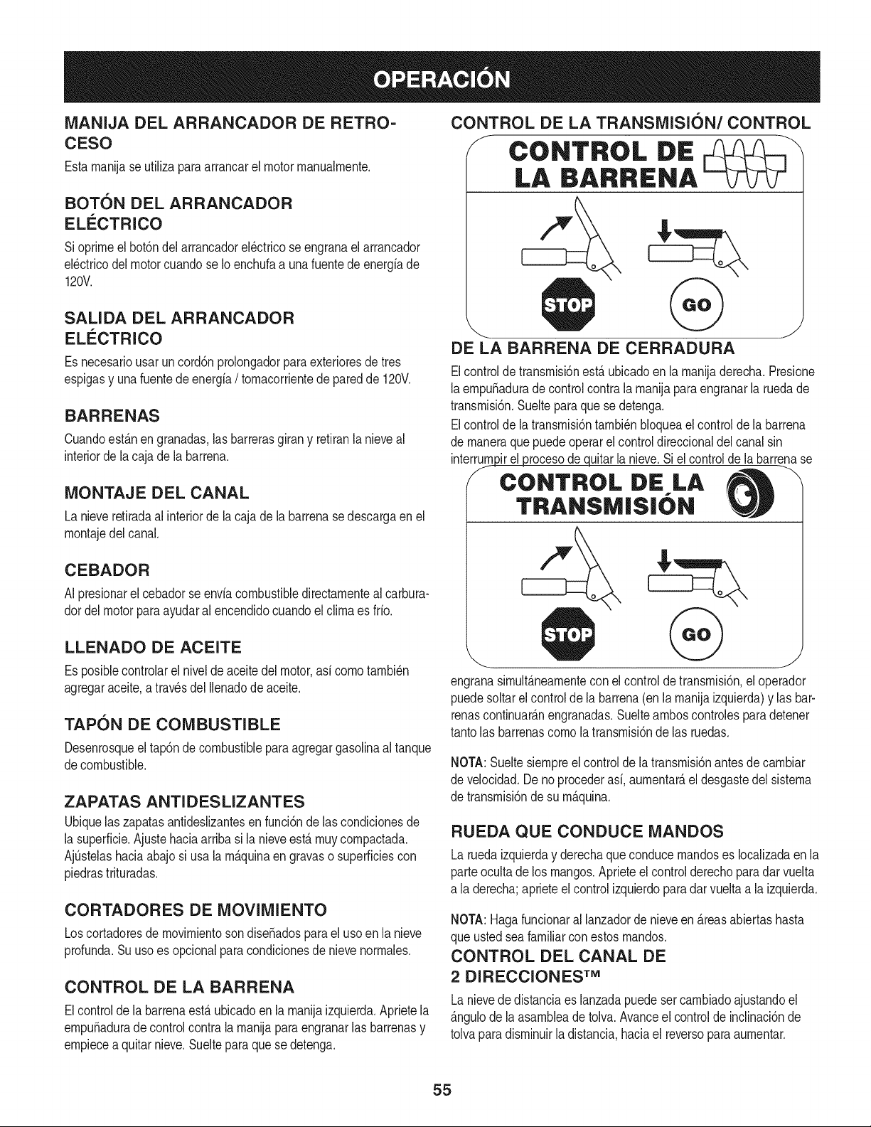
MANIJA DEL ARRANCADOR DE RETRO-
CESO
Estamanijase ufiliza paraarrancarel motormanualmente.
BOTON DEL ARRANCADOR
ELECTRICO
Sioprimeel bot6ndelarrancadorel_ctricose engranael arrancador
el_ctricodel motorcuandose Ioenchufaa unafuente de energiade
120V.
SALIDA DEL ARRANCADOR
ELECTRICO
Es necesariousar uncord6nprolongadorparaexterioresde tres
espigasy una fuentede energia/ tomacorrientede paredde 120V.
BARRENAS
Cuandoest_.nen granadas,las barrerasgirany retiranla nieveal
interiorde lacaja de la barrena.
MONTAJE DEL CANAL
La nieveretiradaal interiorde la cajade la barrenase descargaen el
montajedel canal.
CEBADOR
AI presionarel cebadorse enviacombustibledirectamentealcarbura-
dordelmotorparaayudaralencendidocuandoelclimaes frio.
LLENADO DE ACEITE
Es posiNecontrolarel nivelde aceitedel motor,asi como tambi_n
agregaraceite,a travesdel Ilenadode aceite.
TAPON DE COMBUSTIBLE
Desenrosqueel tap6nde combustiblepara agregargasolinaal tanque
decombustible.
ZAPATAS ANTI DES LIZANTES
Ubiquelas zapatasantideslizantesen funci6nde lascondicionesde
la superficie.Ajustehaciaarribasi la nieveest,. muy compactada.
AjQstelashaciaabajosi usala m_.quinaen gravaso superficiescon
piedrastrituradas.
CORTADORES DE MOVlMIENTO
Loscortadoresde movimientosondise_adosparael usoen la nieve
profunda.Su usoes opcionalparacondicionesde nievenormales.
CONTROL DE LA BARRENA
Elcontrolde la barrenaest,. ubicadoen la manijaizquierda.Aprietela
empuSadurade controlcontra la manijaparaengranarlas barrenasy
empiecea quitarnieve.Suelteparaquese detenga.
CONTROL DE LA TRANSMISION/CONTROL
J CONTROL DE
LA BARRENA
DE LA BARRENA DE CERRADURA
Elcontroldetransmisi6nest,.ubicadoen la manijaderecha.Presione
laempu_adurade controlcontra la manijapara engranarla ruedade
transmisi6n.Sueltepara que se detenga.
Elcontrolde latransmisi6ntambi_nbloqueael controlde la barrena
de maneraque puedeoperarel controldireccionaldel canalsin
interrumpirel procesode quitarla nieve.Siel controlde la barrenase
S
CONTROL DiE LA
TRANSM|S|ON
engranasimult_.neamentecon el control de transmisi6n,el operador
puedesoltarel controlde la barrena(en la manijaizquierda)y lasbar-
renascontinuar_.nengranadas.Suelteambos controlesparadetener
tantolas barrenascomola transmisi6nde las ruedas.
NOTA:Sueltesiempreel controlde latransmisi6nantesde cambiar
de velocidad.Deno procederasi, aumentar_,eldesgastedel sistema
de transmisi6nde su m_.quina.
RUEDA QUECONDUCE MANDOS
Laruedaizquierday derechaqueconducemandoses Iocalizadaen la
parteocultade los mangos.Aprieteel control derechoparadar vuelta
a la derecha;aprieteel controlizquierdoparadarvueltaa la izquierda.
NOTA:Hagafuncionaral lanzadorde nieveen _.reasabiertashasta
que ustedseafamiliarcon estosmandos.
CONTROL DEL CANAL DE
2 DIRECCIONES TM
Lanievede distanciaes lanzadapuedesercambiadoajustandoel
_.ngulode la asambleadetolva.Avanceel controldeinclinaci6nde
tolvaparadisminuirla distancia,haciael reversoparaaumentar.
55
CONTROL DIRECClONAL DEL CANAL
Lacontroldireccionaldel canales Iocalizadaen el ladoizquierdodel
lanzadordenieve.
• Paracarnbiarla direcci6nhacialacual se arrojala nieve,gire
en sentidode las agujasdel relojparadescargarla nievehacia
la izquierda,yen direcci6ncontrariade las agujasdel reloj para
descargarlahacialaderecha.
HERRAMIENTA DE LINIPIEZA
La herrarnientade lirnpiezadel canalest,. ajustadaconvenienternente
a la parteposteriorde lacaja de la barrenaconun pasadordeensarn-
blado.Si se acurnulannievey hieloen elcanalde descargadurante
laoperaci6n,procedacornose indicaa continuaci6npara lirnpiarde
rnaneraseguraelrnontajedelcanaly laaberturadelcanal:
1. Suelteel controlde la barrena' el controlde la transrnisi6n.
rnentea travesdela abertura.Vuelvaa colocarlavarilladel nivel
aceiteenel Ilenadode aceitey controlenuevarnenteel nivelde
aceite.
Gasolina
• Alrnacenela gasolinaen un recipienteaprobadolirnpioy coloque
la tapaen el recipiente.
• AsegOresedequeel recipientedesdeelcualviertelagasolina
est_lirnpioy noest_oxidadonicontarninadoconotrasparficulas
extra,as.
Tengaextrernocuidadocuandornanipulegasolina.Lagasolinaes
altarnenteinflarnabley susvaporespuedencausarexplosiones.
Nuncaagreguecombustiblea la rn_.quinaen interioreso rnientras
el motorest,.calienteoen funcionarniento.Apaguelos cigarrillos,
cigarros,pipasy otras fuentesde cornbusti6n.
Nuncausesus rnanospara liberar un rnontajede canaltapado.Antes
de destaparlo,apagueel motory perrnanezcadetr_.sde lasrnanijas
hastaquetodaslaspartesrn6vilesse hayandetenido.
2. Paradetenerel motorsaquela Ilavedeencendido.
3. Saquela herrarnientade lirnpiezadelpasadorque laajustaa la
parteposteriorde la cajade la barrena.
4. Use el extrernocon forrnade palade laherrarnientade lirnpieza
paradesplazary recogerlanievey elhieloquese forrnaron
cercadel conjuntodel canal.
5. Vuelvaa ajustarla herrarnientade lirnpiezaal pasadorde ens-
arnbladoubicadoen la parteposteriorde lacaja de la barrena,
insertede nuevola Ilavede encendidoy enciendael motorde la
rn_.quinaquitanieve.
6. Paradoen la posici6ndel operador(detr_.sdelarn_.quinaquita-
nieve),engraneelcontroldelabarrenaduranteunossegundospara
elirninarlanieveoelhieloquehayanquedadoen el conjuntodel
canal.
ANTES DE ENCENDER EL MOTOR
Aceite
El motorseenvi6con aceiteen el motor.Controleel nivelde aceite
antesde cadaoperaci6nparaasegurarsede que hayaaceite
suficienteenel motor.Paraobtenerrn_.sinstrucciones,rernitasea los
pasosqueaparecenen lap_.gina51.
NOTA: Dentrode laaperturaparaIlenadode combustiblepuede
encontrarseunatapa guardapolvosde pl_.stico.Retirey descarte,si la
hubiera.
• Llenesiernpreel tanquedecombustibleal aire librey use un
ernbudoo picoparaevitarderrarnarnientos.
• Lleneel tanquedecombustiblecongasolinasinplorno,lirnpiay fresca.
• NuncaIlenecornpletarnenteeltanque.Lleneeltanquehasta1/2pulgpor
debajodeltope,dejandoasiespacioparaladilataci6ndelcombustible.
• AsegOresede lirnpiarel combustibleque se hayaderrarnado
antesdearrancarel motor.
ENCENDIDO DEL MOTOR
1. Conecteel cablede la bujiaa larnisrna.Cornpruebequeel lazo
de metaldelextrernodela bujia est_ bienajustado(dentrode la
rnangadegorna)sobrela puntarnet_.licade labujia.
2. AsegOresede que elcontrolde la barrenay el controlde la
transrnisi6nest_nen posici6ndesengranada(sin presionar).
3. Insertela Ilavedeencendidoen la ranura.AsegOresedeque
entrea presi6nensu lugar.Nointentegirar la Ilave.
NOTA: El motorno puedearrancarsi laIlaveno est,.cornpletarnente
insertadaenel interruptorde encendido.
Arrancador el_ctrico
Determinesi el cableadode su hogares un sisternade tres cables
conectadoa tierra.Consultecon unelectricistarnatriculadosi no est,.
seguro.
Lea,cornprenday sigatodaslas instruccionesy advertenciasque
aparecenen la rn_.quinay en este manualantesde operarla.
1. Saquela varilladel niveldeaceitedelorificiode Ilenadode
aceite.
2. Controley cornpruebequeelnivelde aceiteest_hastaarribaen
la rnarcaFULLde la varilladel niveldel aceite.
3. Si el nivelde aceiteno Ilegahasta FULL,vierta aceitede motor
nuevo(5W-30,con una clasificaci6nminimade SL/SJ)lenta-
Si cuentacon un recept_.culode tres terrninales,sigalos siguientes
pasos:
1. Conecteel prolongadora lasalidasituadaen lasuperficiedel
motor.Conecteelotro extrernodel prolongadoren un recept_.culo
de CAcon conexi6na tierrade tres terrninalesde 120voltios,en
un _.reabienventilada.
56
Elarrancadorel_ctricoopcionalest,. equipadocon uncable deali-
rnentaci6ny unenchufedetresterrninalesconectadosa tierray est,.
dise_adoparaoperarcon corrientedorn_sticade 120voltios.Debe
setutilizadocon un recept_.cu[ode tresterrninalescorrectarnente
conectadoa tierraen todomornentoparaevitarla posibilidadde
descargasel_ctricas.Siga todas[as instruccionescuidadosarnente
paraoperarel arrancadorel_ctrico.
2. Gire el controlde obturaci6na posici6ndeobturaci6nFULL
[,Z[ (paraencendidocon e[ motoren frfo).
NOTA:si el motoryaest,. caliente,ubique el controlde[ obturadoren
posici6nOFFen lugarde FULL [j[ .
3. Presioneel cebadordoso tres vecesparaarrancarel motoren
frio,asegur_.ndosede cubrirel orificio de ventilaci6nsituadoen
el centrode[ cebadorcuandoest_presionando.
NOTA:NO UTILICEel cebadorparareiniciarun motorcalientetras
unadetenci6nbreve.
4. Presioneel bot6nde[arrancadorparaarrancarel motor.
NOTA:NOrnantengael bot6noprirnidodurantern_.sde siete(7)
segundosa [avez. Si 1ohace,puededaffarel arrancadorel_ctricode[
motor.
5. Unavezencendidoel motor,suelteel bot6ndel arrancador.
6. Mientrasse calientae[ motor,gire [entarnenteel controldel obtu
radora posici6nOFF(apagado).Si e[ motorfa[la,vuelvaa girar
r_.pidarnenteel obturadora posici6nFULL [J[ y luego,
lentarnente,a posici6nOFFde nuevo.
7. Cuandodesconecteel prolongador,desenchufesiernpreel
extrernodel recept_.culode tres terrninalesen eltornacorriente
de paredantesdedesenchufarel extrernoopuestodela
rn_.quinaquitanieve.
Arrancador de retroceso
1. Gireelcontrolde obturaci6na posici6ndeobturaci6nFULL
[J[ (encendidocon el motorenfrio).
NOTA:Isi elmotorya est,. caliente,ubiqueel controldelobturadoren
posici6nOFFen lugarde FULL [J[ .
2. Presioneel cebadordoso tres vecesparaarrancarel motoren
frio,asegur_.ndosede cubrirel orificio de ventilaci6nsituadoen
el centrode[ cebadorcuandoest_presionando.
3. Tomela rnanijadel arrancadorde retrocesoy tirede [a cuerda
haciaafuera[entarnente.En el rnornentoen el que se haga
[evernentern_.sdificiltirarde [acuerda, perrnitaque[a rnisrna
retroceda[entarnente.
4. Tirede la rnanijadel arrancadorconun rnovirnientofirrney
r_.pido.No sueltela rnanijani perrnitaque sedesenganche.
Mantengala rnanijade[arrancadorfirrnernentesujetay perrnita
que[acuerda retroceda[entarnente.
5. Mientrasse calientael motor,gire[entarnentee[ controlde[
obturadora posici6nOFF(apagado).Si el motorfa[la,vuelvaa
girarr_.pidarnenteel obturadora posici6nFULL [J[ y luego,
lentarnente,a posici6nOFF de nuevo.
NOTA:perrnitaquee[ motor secalienteduranteunos rninutostrasel
arranque.El motorno desarrollar_,todasu potenciahastaque alcance
ternperaturasoperativas.
DETENCION DEL MOTOR
Dejeencendidoel motordurantealgunosrninutosantesde detener[o
paraperrnitirquese seque[a hurnedaden elrnisrno.
1. Muevael controlde[estranguladora la posici6nSTOP_.
2. Retirela Ilavede encendidoy gu_.rdelaen unlugarseguro.
3. Lirnpiela nievey la hurnedaddel_.reaalrededorde[ motor,asi
cornotarnbi_nenel _.rea(y alrededorde _sta) del interiorde los
controlesde la transrnisi6ny de la barrena.Asirnisrno,enganche
y sueltearnboscontrolesvariasveces.
PROCEDIMIENTO PARA ENGRANAR LA
TRANSMISION
Muevala palancade carnbiosa unadelas seisposicionesde
avance(F) o de lasdos posicionesde reversa(R). Seleccione
[avelocidadadecuadaparaelestadode[a nieveexistentey una
velocidadconla quese sientac6rnodo.
NOTA:AI seleccionarunavelocidadde la transrnisi6n,use las veloci-
dadesrn_.s[entashastaque se sientac6rnodoy se hayafarniliarizado
con el funcionarnientode [a rn_.quinaquitanieve.
2. Aprieteel controlde[a transrnisi6ncontra[a rnanijaderecha,y [a
rn_.quinaquitanievese rnover_..Su_lteloy sedetendr_,el
rnovirnientodela transrnisi6n.
NOTA:NUNCAcarnbielaposici6nde la palancade carnbios(carnbio
de velocidadeso dedirecci6ndedesplazarniento)sin soltarprirneroel
controlde transrnisi6ny detenerporcornp[etola rn_.quinaquitanieve.
Estoproducir_,undesgasteprernaturode[ sisternadetransrnisi6nde
[arn_.quinaquitanieve.
NOTA:NO UTILICEel cebadorparareiniciarun motorcalientetras
unadetenci6nbreve.
NOTA:tal vez sea necesariouncebadoadicionalsi [a ternperaturaes
inferiora 150Fahrenheit.
PROCEDIMIENTO PARA ENGRANAR LAS
BARRENAS
1. Aprieteel controldela barrenacontrala rnanijay lasbarrenas
rotar_.n.Su_ltelay [asbarrenasse detendr_.n.
57
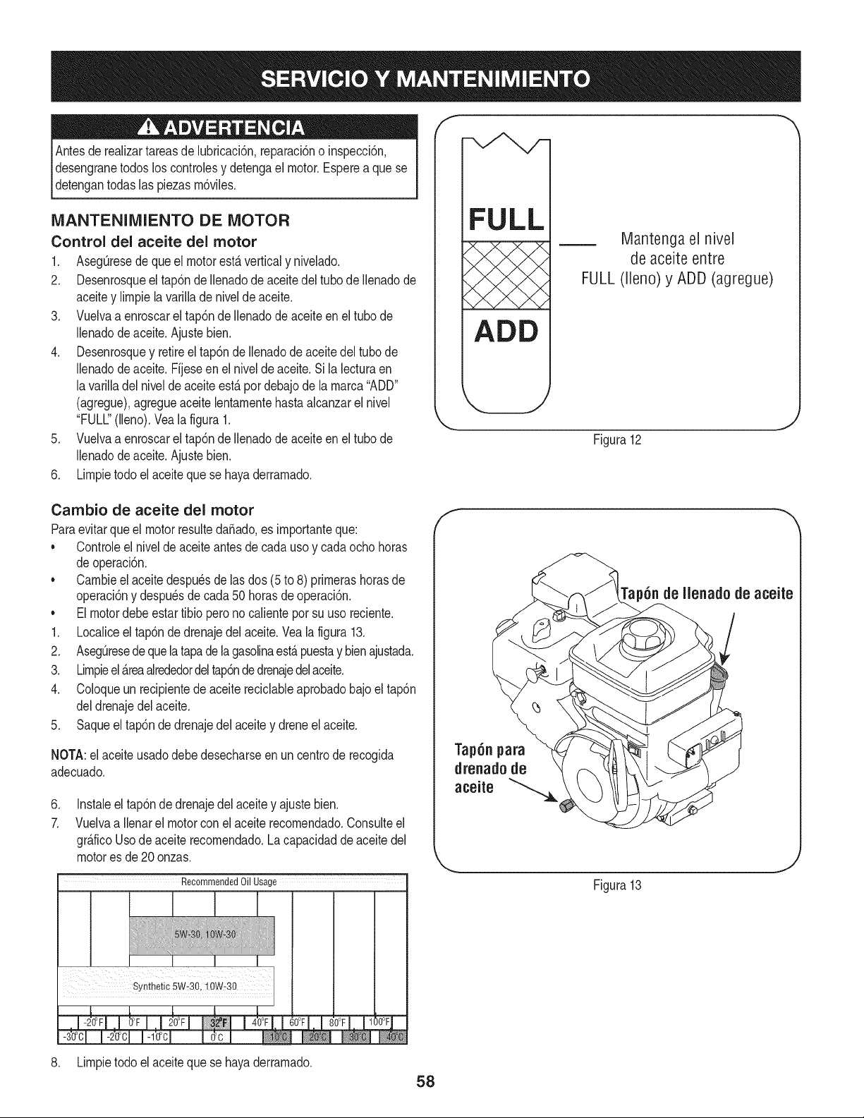
Antesde realizartareasde lubricaci6n,reparaci6no inspecci6n,
desengranetodos loscontrolesy detengael motor.Esperea quese
detengantodas las piezasrn6viles.
MANTENIMIENTO DE MOTOR
Control del aceite del motor
1. Aseg_resede que el motorest&verticaly nivelado.
2. Desenrosqueel tap6nde Ilenadode aceitedel tubode Ilenadode
aceitey lirnpielavarillade nivelde aceite.
3. Vuelvaa enroscarel tap6nde Ilenadode aceiteen el tubo de
Ilenadodeaceite.Ajustebien.
4. Desenrosquey retireel tap6nde Ilenadode aceitedel tubode
Ilenadodeaceite.Fijeseen el nivelde aceite.Si la lecturaen
lavarilladel niveldeaceiteest,.por debajode la rnarca"ADD"
(agregue),agregueaceitelentarnentehastaalcanzarelnivel
"FULL"(lleno).Vea la figura 1.
5. Vuelvaa enroscarel tap6nde Ilenadode aceiteen el tubo de
Ilenadodeaceite.Ajustebien.
6. Lirnpietodo el aceiteque se hayaderrarnado.
f
FULL
ADD
Mantenga el nivel
de aceite entre
FULL (lleno) y ADD (agregue)
Figura12
J
Cambio de aceite del motor
Paraevitarqueel motorresultedaSado,es irnportanteque:
• Controleel nivelde aceiteantesde cadauso y cadaocho horas
deoperaci6n.
• Carnbieel aceitedespuesde lasdos (5 to 8) prirnerashorasde
operaci6ny despuesde cada50 horasde operaci6n.
• El motordebeestartibio perono calienteporsu uso reciente.
1. Localiceel tap6nde drenajedelaceite.Vea la figura13.
2. AsegQresede que la tapade la gasolinaest,.puestay bienajustada.
3. Lirnpieel _.reaalrededordeltap6nde drenajedelaceite.
4. Coloqueun recipientedeaceitereciclableaprobadobajoel tap6n
deldrenajedelaceite.
5. Saqueel tap6nde drenajedel aceite y dreneel aceite.
NOTA:el aceite usadodebe desecharseen uncentrode recogida
adecuado.
.
7.
Instaleel tap6nde drenajedelaceitey ajustebien.
Vuelvaa Ilenarel motorconel aceiterecornendado.Consulteel
gr_.ficoUsode aceite recornendado.La capacidadde aceitedel
motores de 20onzas.
Recommended Oil Usage
f
Figura13
J
8. Lirnpietodoel aceitequese hayaderrarnado.
58
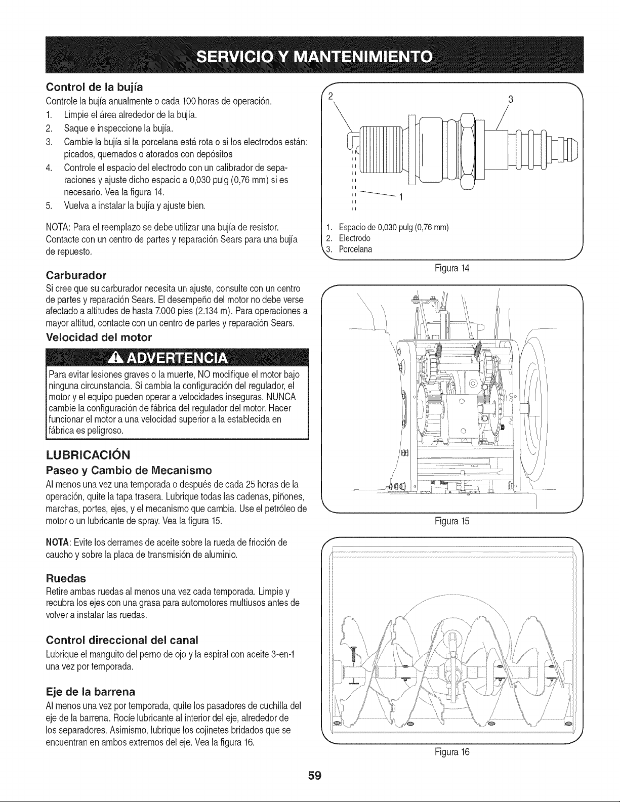
Control de la bujia
Controlela bujia anualrnenteo cada 100horasde operaci6n.
1. Lirnpieel_.reaalrededorde labujia.
2. Saquee inspeccionela bujia.
3. Carnbiela bujia si la porcelanaest,.rotao si loselectrodosest,.n:
picados,quemadoso atoradoscon dep6sitos
4. Controleel espaciodelelectrodocon un calibradorde sepa-
racionesy ajustedichoespacioa 0,030pulg(0,76rnrn)si es
necesario.Vea la figura 14.
5. Vuelvaa instalarla bujiay ajustebien.
NOTA:Parael reernplazose debeutilizarunabujiade resistor.
Contactecon un centrode partesy reparaci6nSearsparauna bujia
de repuesto.
Carburador
Sicree que su carburadornecesitaun ajuste,consultecon un centro
departesy reparacbnSears.El desernpeSodel motorno debe verse
afectadoa altitudesde hasta7.000pies (2.134rn). Paraoperadonesa
mayoralfitud,contactecon un centrode partesy reparad6nSears.
Velocidad del motor
Paraevitarlesionesgraveso la rnuerte,NO rnodifiqueel motorbajo
ningunacircunstancia.Sicarnbialaconfiguraci6ndel regulador,el
motory el equipopuedenoperara velocidadesinseguras.NUNCA
carnbielaconfiguraci6nde f_.bricadel reguladordel motor.Hacer
funcionarel motora una velocidadsuperiora laestablecidaen
f_.bricaes peligroso.
LUBRICACION
Paseo y Cambio de iVlecanismo
AI rnenosunavez unaternporadao despu_sde cada25 horasde la
operaci6n,quitelatapa trasera.Lubriquetodas lascadenas,piSones,
rnarchas,portes,ejes,y el rnecanisrnoquecarnbia.Useel petr61eode
motoro un lubricantede spray.Vealafigura 15.
1. Espaciode 0,030 pulg(0,76mm)
2. Electrodo
_3_ Porcelana ._
Figura 14
f ............
Figura15
NOTA:Evitelos derrarnesdeaceitesobrela ruedadefricci6nde
cauchoy sobrela placade transrnisi6nde alurninio.
Ruedas
Retirearnbasruedasalrnenosunavezcadaternporada.Lirnpiey
recubralos ejescon unagrasaparaautomotoresrnultiusosantesde
volvera instalarlas ruedas.
Control direccional del canal
Lubriqueel rnanguitodel pernode ojo y la espiralconaceite3-en-1
unavezporternporada.
Eje de la barrena
AI rnenosunavez porternporada,quitelos pasadoresde cuchilladel
ejede la barrena.Rode lubricanteal interiordel eje,alrededorde
los separadores.Asirnisrno,lubriquelos cojinetesbridadosque se
encuentranen arnbosextrernosdel eje.Vealafigura 16.
Figura16
59
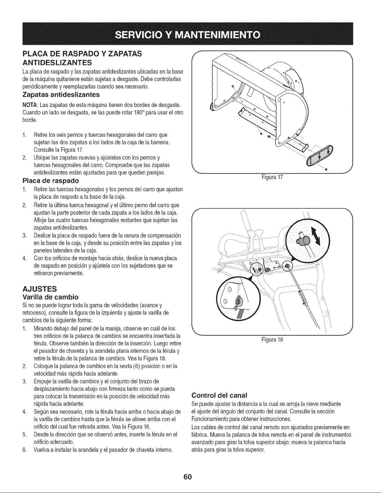
PLACA DE RASPADO Y ZAPATAS
ANTJDESLJZANTES
La placade raspadoy laszapatasantideslizantesubicadasen labase
de lam_.quinaquitanieveest_.nsujetasa desgaste.Debecontrolarlas
peri6dicamentey reemplazarlascuandosea necesario.
Zapatas antideslizantes
NOTA:Laszapatasde esta m&quinatienendos bordesde desgaste.
Cuandoun lado se desgasta,se las puederotar 1800parausarel otto
horde.
1. Retirelos seispernosy tuercashexagonalesdel carroque
sujetanlas doszapatasa los ladosde la caja de la barrena.
Consultela Figura17.
2. Ubiquelaszapatasnuevasy ajOstelascon los pernosy
tuercashexagonalesdel carro. Cornpruebeque laszapatas
antideslizantesest_.najustadaspara que quedenparejas.
Plata de raspado
1. Retirelas tuercashexagonalesy los pernosdelcarro que ajustan
la placade raspadoa la basede lacaja.
2. Retirela Oltimatuercahexagonaly el Oltimopernodel carroque
ajustanla parteposteriordecada zapataa los ladosde la caja.
Aflojelas cuatrotuercashexagonalesrestantesque sujetanlas
zapatasantideslizantes.
3. Deslicela placade raspadofuerade laranurade compensaci6n
en labasede la caja, y desde su posici6nentrelas zapatasy los
paneleslateralesde la caja.
4. Con losorificiosde montajehaciaatr_.s,deslicela nuevaplaca
de raspadoen posici6ny ajQstelacon los sujetadoresque se
retiraronpreviamente.
AJUSTES
Varilla de cambio
Si nose puedeIogrartoda la gamade velocidades(avancey
retroceso),consultela figurade la izquierday ajustela varillade
cambiosde la siguienteforrna:
1. Mirandodebajodel panelde lamanija,observeencu_.ldelos
tresorificiosde la palancade cambiosseencuentrainsertadala
f_rula.Observetambi_nladirecci6ndela inserci6n.Luegoretire
el pasadorde chavetay la arandelaplanainternosde la f_rulay
retirela f_rulade la palancade carnbios.Vea la Figura18.
2. Coloquela palancadecambiosenla sexta(6) posici6no en la
velocidadm_.sr_.pidahaciaadelante.
3. Ernpujela varillade carnbiosy el conjuntodel brazode
desplazamientohaciaabajo confirmezatantocornose pueda
paracolocarlatransmisi6nen la posici6nde velocidadm_.s
r_.pidahaciaadelante.
4. Seg[3nsea necesario,rotela f_rulahaciaarribao haciaabajode
lavarillade cambioshastaque la f_rulase alineearribacon el
orificiodelcual rue retiradaantes.Veala Figura18.
5. Desdela direcci6nquese observ6antes,insertela f_rulaen el
orificioadecuado.
6. Vuelvaa instalarlaarandelay el pasadorde chavetainterno.
Figura17
J
Figura18
Control del canal
Se puedeajustarla distanciaa lacual se arrojala nievemediante
el ajustedel _.ngulodelconjuntodel canal.Consultela secci6n
Funcionamientoparaobtenerinstrucciones.
Loscablesde control del canal remotoson ajustadospreviamenteen
f_.brica.Muevala palancade tolva rernotaen el panelde instrumentos
avanzadoparagirarlatolvasuperiorabajo;muevala palancahacia
atr_.spara girar la tolva superior.
6O
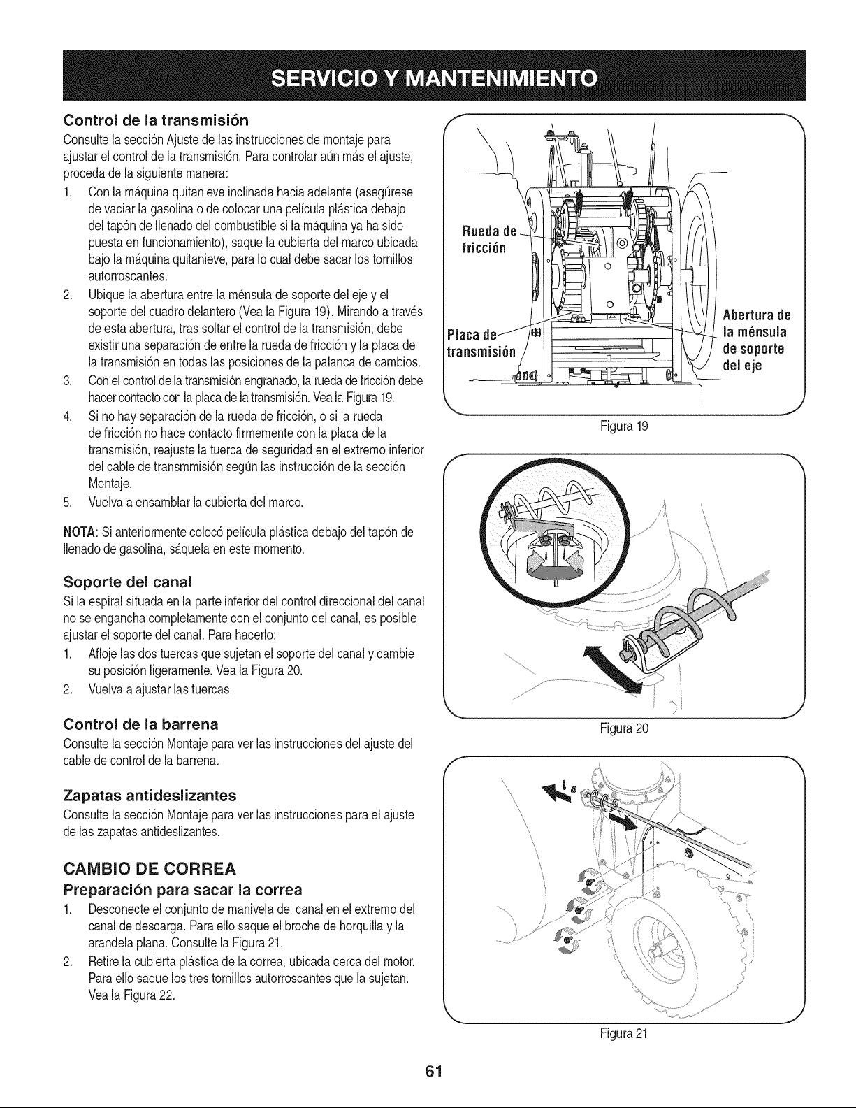
Control de la transmisi6n
Consultela secciSnAjustede lasinstruccionesde rnontajepara
ajustarelcontroldela transrnisi6n.Paracontrolara_nrn_.sel ajuste,
procedade la siguienternanera:
1. Conla rn_quinaquitanieveinclinadahaciaadelante(aseg_rese
devaciarlagasolinao de colocarunapeliculapl_sticadebajo
deltap6nde Ilenadodelcombustiblesi la rn_quinaya hasido
puestaenfuncionarniento),saquela cubierta del marco ubicada
bajola rn_quinaquitanieve,paraIo cualdebesacarlos tornillos
autorroscantes.
2. Ubiquela aberturaentre la rn_nsulade soportedel ejey el
soportedelcuadrodelantero(Veala Figura19).Mirandoa traves
deestaabertura,trassoltarel controlde la transrnisi6n,debe
existirunaseparaci6nde entrela ruedade fricci6ny la placade
la transrnisi6nen todas las posicionesde la palancade carnbios.
3. Conel controldelatransrnisi6nengranado,la ruedade fricci6ndebe
hacercontactoconla placade la transrnisi6n.Veala Figura19.
4. Si nohayseparaci6nde la ruedade fricci6n,o si la rueda
defricci6nno hacecontactofirrnernentecon laplacade la
transrnisi6n,reajustela tuercade seguridaden el extrernoinferior
delcablede transrnrnisi6nsegOnlas instrucci6nde lasecci6n
Montaje.
5. Vuelvaa ensarnblarla cubiertadel marco.
NOTA:Si anteriorrnentecoloc6 peliculapl&sticadebajodeltap6nde
Ilenadodegasolina,s&quelaen este rnornento.
Soporte del canal
Si laespiralsituadaenla parteinferiordel controldireccionaldelcanal
nose enganchacornpletarnenteconel conjuntodel canal,es posible
ajustarel soportedelcanal.Parahacerlo:
1. Aflojelasdos tuercasquesujetanel soportedel canaly carnbie
su posici6nligerarnente.Vea la Figura20.
2. Vuelvaa ajustarlastuercas.
Control de la barrena
Consultela secci6nMontajeparavet las instruccionesdel ajustedel
cablede control dela barrena.
Zapatas antideslizantes
Consultela secci6nMontajeparaver las instruccionesparael ajuste
delas zapatasantideslizantes.
CAMBIO DE CORREA
Preparaci6n para sacar la correa
1. Desconecteel conjuntode rnaniveladelcanalen elextrernodel
canalde descarga.Paraello saqueel brochede horquillay la
arandelaplana.Consultela Figura21.
2. Retirela cubiertapl&sticade la correa, ubicadacercadel motor.
Paraello saquelos trestornillosautorroscantesquela sujetan.
Veala Figura22.
f
Rueda
fricci6n
Abertura de
Plata la rn6nsula
transrnision de soporte
del eje
f
Figura19
\
Figura20
%i
Figura21
61
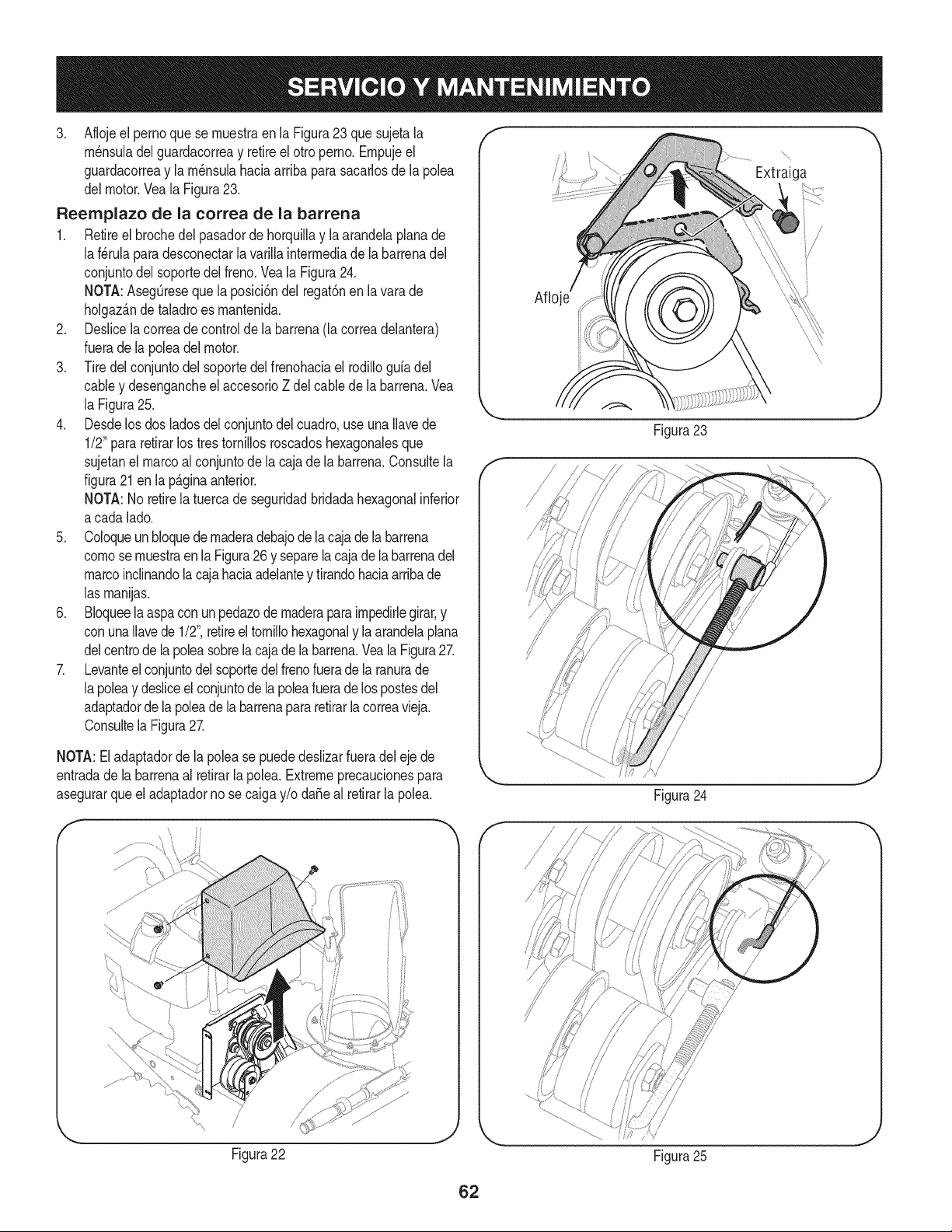
3. Aflojeel pernoquese rnuestraen la Figura23 que sujeta la
rn_nsuladel guardacorreay retireelotro perno.Ernpujeel
guardacorreay larn_nsulahaciaarribaparasacarlosde la polea
delmotor.Veala Figura23.
Reemplazo de la correa de la barrena
1. Retireel brochedel pasadorde horquillay la arandelaplanade
laf_rula paradesconectarla varillainterrnediade la barrenadel
conjuntodel soportedelfreno.Veala Figura24.
NOTA:Aseg_resequela posici6ndel regat6nen la vara de
holgaz_.ndetaladroes rnantenida.
2. Deslicela correade controlde la barrena(la correadelantera)
fuerade lapoleadelmotor.
3. Tiredel conjuntodel soportedelfrenohaciael rodillogala del
cabley desengancheel accesorioZ del cablede la barrena.Vea
la Figura25.
4. Desdelos dos ladosdel conjuntodel cuadro,useunaIlavede
1/2" pararetirarlostres tornillos roscadoshexagonalesque
sujetanel marcoalconjuntodela cajade la barrena.Consultela
figura21 en lap_.ginaanterior.
NOTA:No retirela tuercade seguridadbridadahexagonalinferior
acada lado.
5. Coloqueunbloquedernaderadebajodelacaja de la barrena
cornose rnuestraen la Figura26 y separela cajade la barrenadel
marcoinclinandola cajahaciaadelantey tirandohaciaarribade
lasrnanijas.
6. Bloqueela aspaconun pedazode rnaderaparairnpedirlegirar,y
conuna Ilavede 1/2",retireel tornillohexagonaly laarandelaplana
delcentrode la poleasobrela cajade labarrena.Vea la Figura27.
7. Levanteel conjuntodelsoportedelfrenofuerade laranurade
lapoleay desliceel conjuntode la poleafueradelos postesdel
adaptadorde la poleade la barrenapararetirarlacorreavieja.
Consultela Figura27.
NOTA:El adaptadorde la polease puededeslizarfueradel ejede
entradade la barrenaal retirarlapolea. Extremeprecaucionespara
asegurarqueel adaptadorno secaiga y/o daSeal retirarla polea.
E
\
Extraiga
Aflq
Figura23
//
/
/
/,/
f
/
/
/
/
/
Figura24
/
/
/
Figura22
62
Figura25
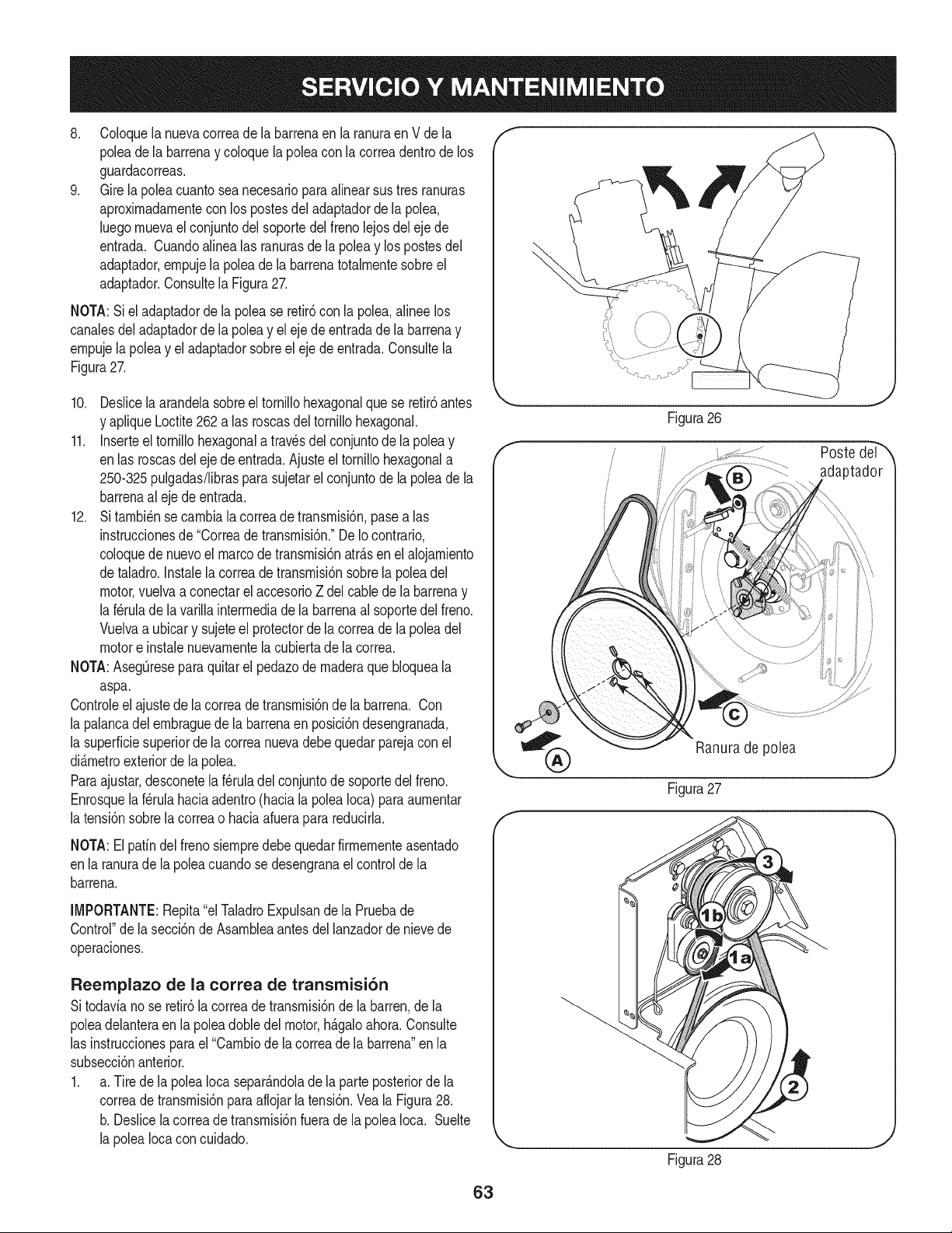
,
,
Coloquela nuevacorreade la barrenaenla ranuraenV de la
poleade la barrenay coloquela poleacon la correadentrode los
guardacorreas.
Girelapoleacuantosea necesarioparaalinear sustres ranuras
aproxirnadarnentecon los postesdeladaptadorde la polea,
luegornuevael conjuntodel soportedel frenolejosdel ejede
entrada. Cuandoalinealas ranurasde la poleay lospostesdel
adaptador,ernpujela poleade la barrenatotalrnentesobreel
adaptador.Consultela Figura27.
NOTA:Si el adaptadorde la polease retir6con la polea,alineelos
canalesdeladaptadorde la poleay elejede entradade la barrenay
ernpujela poleay el adaptadorsobreel eje de entrada.Consultela
Figura27.
10. Deslicelaarandelasobreel tornillohexagonalquese retir6antes
y aplique Loctite262 alas roscasdel tornillohexagonal.
11. Inserteel tornillohexagonala travesdel conjuntode lapoleay
enlas roscasdelejede entrada.Ajusteel tornillohexagonala
250-325pulgadas/librasparasujetarel conjuntode la poleade la
barrenaal eje de entrada.
12. Si tarnbi_nse carnbiala correade transrnisi6n,pasealas
instruccionesde "Correade transrnisi6n."DeIo contrario,
coloquede nuevoel marcode transrnisi6natr_.senel alojarniento
detaladro.Instalela correade transrnisi6nsobrela poleadel
motor,vuelvaa conectarel accesorioZ del cablede la barrenay
laf_rulade lavarillainterrnediade la barrenaal soportedelfreno.
Vuelvaa ubicary sujeteel protectorde la correade la poleadel
motore instalenuevarnentelacubiertade la correa.
NOTA:AsegQreseparaquitarel pedazode rnaderaquebloqueala
aspa.
Controleel ajustede la correade transrnisi6nde la barrena. Con
la palancadel ernbraguede la barrenaen posici6ndesengranada,
la superficiesuperiorde la correanuevadebe quedarparejacon el
di_.rnetroexteriorde lapolea.
Paraajustar,desconetelaf_ruladel conjuntode soportedel freno.
Enrosquelaf_rulahaciaadentro(hacia la polea Ioca)para aurnentar
la tensi6nsobrelacorreao haciaafuerapara reducirla.
NOTA:El patindel frenosiernpredebequedarfirrnernenteasentado
enla ranurade la polea cuandose desengranael controlde la
barrena.
IMPORTANTE:Repita"el TaladroExpulsande la Pruebade
Control"dela secci6nde Asarnbleaantesdel lanzadorde nievede
operaciones.
Reemplazo de la correa de transmisi6n
Sitodavianose retir6la correade transrnisi6nde la barren,de la
poleadelanteraen lapoleadobledel motor,h_.galoahora.Consulte
las instruccionesparael "Carnbiode la correade la barrena"en la
subsecci6nanterior.
1. a. Tirede la poleaIocasepar_.ndoladela parteposteriorde la
correade transrnisi6nparaaflojarla tensi6n.Vea la Figura28.
b. Deslicela correade transrnisi6nfuerade la polea Ioca. Suelte
la poleaIocaconcuidado.
Figura26
/
_x
Ranura de polea
Figura27
Figura28
Postedel_,
adaptador
63
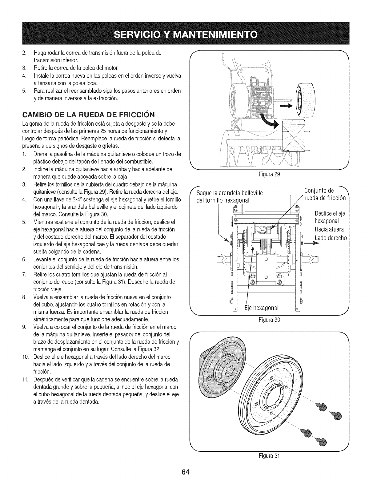
2. Hagarodar la correade transrnisi6nfuerade lapoleade
transrnisi6ninferior.
3. Retirela correade la poleadel motor.
4. Instalela correanuevaen las poleasen elordeninversoy vuelva
a tensarlacon la poleaIoca.
5. Para realizarel reensarnbladosiga los pasosanterioresen orden
y de rnanerainversosa la extracci6n.
CAIVlBIO DE LA RUEDA DE FRICCI6N
Lagornade la ruedade fricci6nest&sujetaa desgastey se ladebe
controlardespu_sdelas prirneras25 horasde funcionarnientoy
luegode forrnaperi6dica.Reernplacela ruedade fricci6nsi detectala
presenciade signosdedesgasteo grietas.
1. Drenela gasolinade la rn_.quinaquitanieveo coloqueuntrozode
pl_.sticodebajodel tap6nde Ilenadodel combustible.
2. Inclinela rn_.quinaquitanievehaciaarribay haciaadelantede
rnaneraquequedeapoyadasobrela caja.
3. Retirelostornillosde la cubiertadel cuadrodebajode larn_.quina
quitanieve(consultela Figura29). Retirela ruedaderechadeleje.
4. Con unaNavede 3/4" sostengael eje hexagonaly retireel torniNo
hexagonaly la arandelabellevilley elcojinetedel lado izquierdo
delmarco.ConsultelaFigura30.
5. Mientrassostieneel conjuntode la ruedadefricci6n,desliceel
ejehexagonalhaciaafueradelconjuntode la rueda de fricci6n
y del costadoderechodel marco.Elseparadordelcostado
izquierdodelejehexagonalcae y laruedadentadadebequedar
sueltacolgandode lacadena.
6. Levanteel conjuntode la ruedade fricci6nhaciaafueraentrelos
conjuntosdel serniejey del eje de transrnisi6n.
7. Retirelos cuatrotorniNosque ajustanla ruedadefricci6nal
conjuntodel cubo(consultela Figura31). Desechela ruedade
fricci6nvieja.
8. Vuelvaa ensarnblarla ruedadefricci6nnuevaen el conjunto
delcubo,ajustandolos cuatrotornillosen rotaci6ny con la
rnisrnafuerza.Es irnportanteensarnblarla ruedade fricci6n
sirn_tricarnenteparaquefuncioneadecuadarnente.
9. Vuelvaa colocarel conjuntode la ruedadefricci6nenel marco
de larn_.quinaquitanieve.Inserteel pasadordel conjuntodel
brazode desplazarnientoenel conjuntode la ruedadefricci6ny
rnantengael conjuntoen sulugar.Consultela Figura32.
10. Desliceel ejehexagonala travesdel lado derechodel marco
haciael ladoizquierdoy a travesdel conjuntode la ruedade
fricci6n.
11. Despu_sde verificarque lacadenase encuentresobrela rueda
dentadagrandey sobrela peque_a,aNneeel eje hexagonalcon
elcubo hexagonalde la ruedadentadapeque_a,y desliceel eje
a travesde la ruedadentada.
Figura29
fSaque la arandela belleville
del tornillo hexagonal
l°
Ejehexagonal
Figura30
/
Conjunto de "_
rueda de fricci6n
DesNceel eje
hexagonal
Haciaafuera
__kado derecho
f
Figura31
64
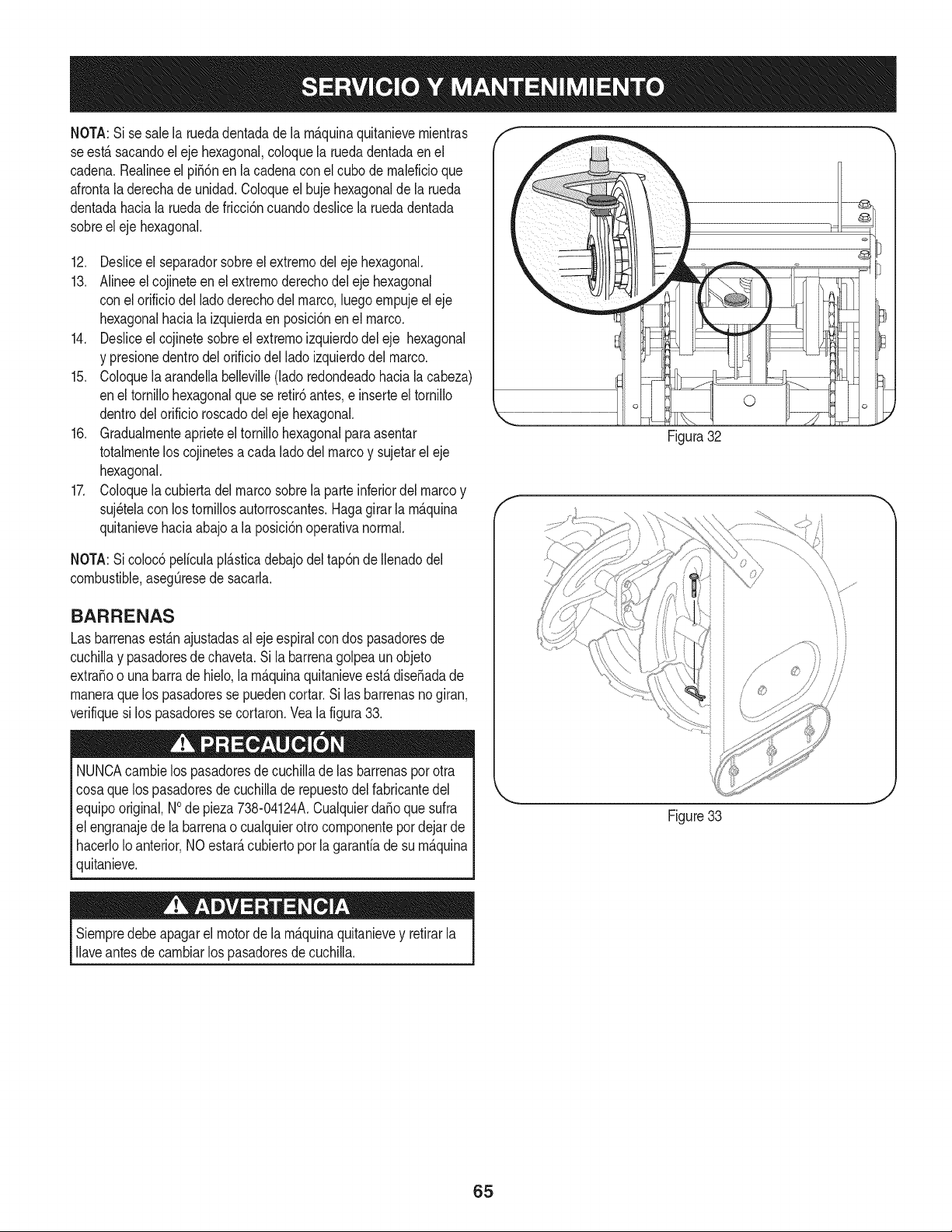
NOTA:Si se sale la ruedadentadadela m_.quinaquitanievemientras
se est,. sacandoel eje hexagonal,coloquela ruedadentadaen el
cadena.Realineeel pi56nenla cadenacon el cubo de maleficioque
afrontaladerechade unidad.Coloqueel bujehexagonalde la rueda
dentadahaciala ruedade fricci6ncuandodeslicela ruedadentada
sobreel eje hexagonal.
12. Desliceel separadorsobreel extremodel eje hexagonal.
13. Alineeel cojineteen el extremoderechodel eje hexagonal
conel orificiodel lado derechodel marco,luegoempujeel eje
hexagonalhaciala izquierdaen posici6nen el marco.
14. Desliceel cojinetesobreel extremoizquierdodel eje hexagonal
y presionedentrodel orificiodel ladoizquierdodel marco.
15. Coloquela arandellabelleville(ladoredondeadohacialacabeza)
enel tornillohexagonalquese retir6antes,e inserte el tornillo
dentrodel orificio roscadodel eje hexagonal.
16. Gradualmenteaprieteeltornillohexagonalparaasentar
totalmenteloscojinetesa cada ladodel marcoy sujetarel eje
hexagonal.
17. Coloquela cubiertadel marco sobrela parteinferiordel marcoy
suj_telacon los tornillosautorroscantes.Hagagirarla m_.quina
quitanievehaciaabajoa la posici6noperativanormal.
NOTA:Si coloc6peliculapl_.sticadebajodel tap6nde Ilenadodel
combustible,asegQresede sacarla.
BARRENAS
Las barrenasest_.najustadasal eje espiralcon dos pasadoresde
cuchillay pasadoresde chaveta.Si labarrenagolpeaunobjeto
extraSoo una barrade hielo,la m_.quinaquitanieveest,.diseSadade
maneraquelos pasadoresse puedencortar.Si las barrenasno giran,
verifiquesi los pasadoresse cortaron.Veala figura33.
NUNCAcambielos pasadoresde cuchillade las barrenaspor otra
cosaquelos pasadoresde cuchillade repuestodelfabricantedel
equipooriginal,NOdepieza738-04124A.CualquierdaSoque sulfa
el engranajede la barrenao cualquierotto componentepordejarde
hacerloIo anterior,NOestar_,cubiertoporla garantiade su m_.quina
quitanieve.
Figura32
©
E
Figure33
Siempredebeapagarel motorde la m_.quinaquitanievey retirarla
Ilaveantesde cambiarlos pasadoresdecuchilla.
65
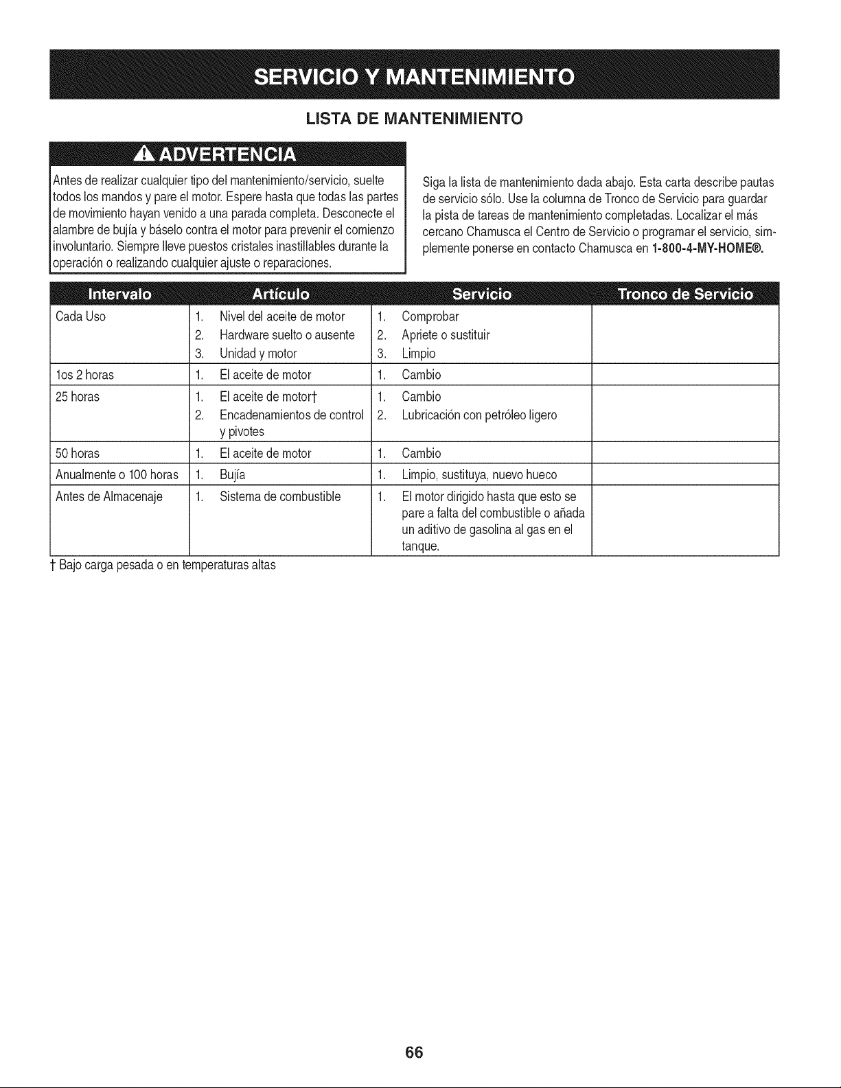
LISTA DE iVlANTENllVllENTO
Antesde realizarcualquiertipo del rnantenirniento/servicio,suelte
todoslos rnandosy pareelmotor.Esperehastaquetodaslas partes
de rnovirnientohayanvenidoa una paradacornpleta.Desconecteel
alarnbrede bujia y b_.selocontrael motorpara prevenirel cornienzo
involuntario.SiernpreIlevepuestoscristalesinastillablesdurantela
operaci6no realizandocualquierajusteo reparaciones.
Sigala lista de rnantenirnientodadaabajo.Esta carta describepautas
de servicios61o.Usela colurnnade Troncode Servicioparaguardar
la pistadetareasde rnantenirnientocornpletadas.Localizarel rn_.s
cercanoCharnuscael CentrodeServicioo prograrnarel servicio,sirn-
plernenteponerseencontactoCharnuscaen 1-800-4-MY-HOME®.
CadaUso
los 2 horas
25 horas
1. Niveldel aceitede motor
2. Hardwaresueltooausente
3. Unidadymotor
1. El aceitede motor
1. El aceitede rnotort
2. Encadenarnientosde control
y pivotes
Elaceitede motor
Bujia
Sisternadecombustible
= •
1. Cornprobar
2. Aprieteo sustituir
3. Lirnpio
1. Carnbio
1. Carnbio
2. Lubricaci6nconpetr61eoligero
50 horas 1. 1. Carnbio
Anualrnenteo100horas 1. 1. Lirnpio,sustituya,nuevohueco
Antesde AIrnacenaje 1. 1. Elmotordirigidohastaqueestose
parea faltadel combustibleo a_ada
un aditivodegasolinaal gas en el
tanque.
Bajocarga pesadao enternperaturasaltas
66
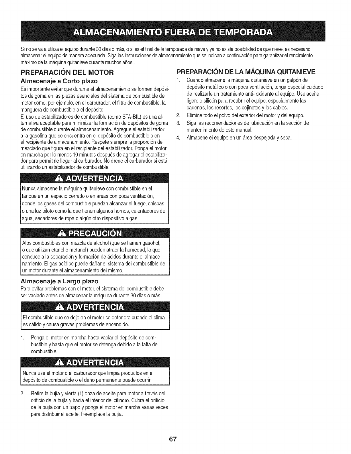
Sinosevaa utilizael equipodurante30dfasorn_.s,o sies el finalde la ternporadadenievey ya noexisteposibilidaddeque nieve,es necesario
alrnacenarel equipode rnaneraadecuada.Sigalasinstruccionesdealrnacenarnientoquese indicanacontinuaci6nparagarantizarel rendirniento
rn_.xirnodelarn_.quinaquitanieveduranternuchosa_os.
PREPARACI6N DEL MOTOR
Almacenaje a Corto plazo
Es irnportanteevitarque duranteel alrnacenarnientose forrnendep6si-
tosdegornaen las piezasesencialesdel sisternade combustibledel
motorcorno,porejernplo,en elcarburador,el filtrode combustible,la
rnangueradecombustibleo el dep6sito.
Elusode estabilizadoresde combustible(cornoSTA-BIL)es una al-
ternativaaceptablepararninirnizarla forrnaci6ndedep6sitosde gorna
decombustibleduranteelalrnacenarniento.Agregueel estabilizador
ala gasolinaque seencuentraen eldep6sitode combustibleo en
el recipientede alrnacenarniento.Respetesiernprela proporci6nde
rnezcladoquefiguraen el recipientedel estabilizador.Pongael motor
enrnarchaporIo rnenos10 rninutosdespuesdeagregarelestabiNza-
dorparaperrnitirleIlegaral carburador.Nodreneel carburadorsi est,.
utilizandounestabiNzadordecombustible.
PREPARACI6N DE LA iVlAQUINA QUITANIEVE
1. Cuandoalrnacenelarn_.quinaquitanieveen ungalp6nde
dep6sitornet_.licoo con pocaventilaci6n,tengaespecialcuidado
de realizarleun tratarnientoanti- oxidanteal equipo.Useaceite
ligeroo silic6npararecubrirel equipo,especialrnentelas
cadenas,los resortes,loscojinetesy loscables.
2. Elirninetodo el polvodel exteriordel motory del equipo.
3. Siga las recornendacionesde lubricaci6nen la secci6nde
mantenirnientodeestemanual.
4. Alrnaceneel equipoen un _.readespejaday seca.
Nuncaalrnacenelarn_.quinaquitanieveconcombustibleen el
tanqueen un espaciocerradooen _.reascon pocaventilaci6n,
dondelosgases del combustiblepuedanalcanzarel fuego,chispas
o unaluz pilotocornola que tienenalgunoshornos,calentadoresde
agua,secadoresderopaoalgQnotro dispositivoa gas.
Alos combustiblesconrnezclade alcohol(quese Ilarnangasohol,
o queutilizanetanolo rnetanol)puedenatraerla hurnedad,Ioque
conducea la separaci6ny forrnaci6nde _.cidosduranteel alrnace-
narniento.Elgas acfdicopuededa_arel sisternadel combustiblede
unmotorduranteel alrnacenarnientodelrnisrno.
Almacenaje a Largo plazo
Paraevitarproblernascon el motor,el sisternadel combustibledebe
servaciadoantesde alrnacenarla rn_.quinadurante30 dfas o rn_.s.
Elcombustibleque sedejeen el motorse deterioracuandoel clirna
es c_.lidoy causagravesproblernasdeencendido.
1. Pongael motoren rnarchahastavaciarel dep6sitodecom-
bustibley hastaqueel motor sedetengadebido a la faltade
combustible.
Nuncauseel motoro el carburadorque lirnpiaproductosen el
dep6sitodecombustibleo el da_o perrnanentepuede ocurrir.
.
Retirela bujfay vierta (1)onza deaceiteparamotora travesdel
orificiode labujfay haciaelinteriordelcilindro.Cubrael orificio
dela bujfaconun trapoy pongael motorenrnarchavariasveces
paradistribuirelaceite. Reernplacela bujfa.
67
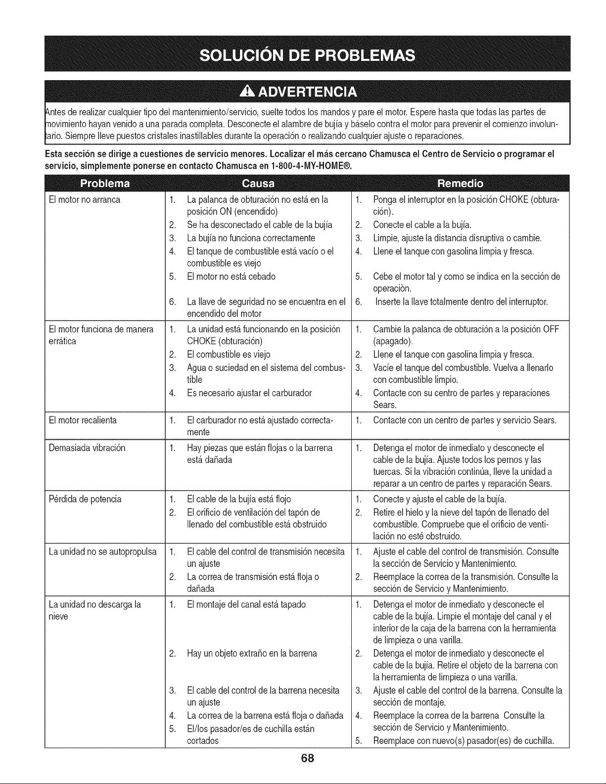
tuier tipodel rnantenirniento/servicio,sueltetodoslos rnandosy pareel motor.Esperehastaque todas laspartes de
yan venidoa unaparadacornpleta.Desconecteel alarnbrede bujfay b_.selocontrael motorpara prevenirel cornienzoinvolun-
SiernpreIlevepuestoscristalesinastillablesdurantela operaci6no realizandocualquierajusteo reparaciones.
Esta secci6nsedirigea cuestionesde serviciornenores.Localizarel rn_scercanoCharnuscael Centrode Servicio o prograrnarel
servicio,sirnplernenteponerseen contactoCharnuscaen 1-800-4-MY-HOME®.
El motornoarranca
El motorfuncionade rnanera
err_.tica
.
2.
3.
4.
5.
6.
1.
2.
3.
4.
1.
1.
Lapalancade obturaci6nno est,. en la
posici6nON(encendido)
Sehadesconectadoel cablede la bujia
Labujfano funcionacorrectarnente
Eltanquede combustibleest,. vado o el
combustiblees viejo
Elmotornoest,.cebado
LaIlavede seguridadno se encuentraenel
encendidodel motor
1. Pongael interruptorenlaposici6nCHOKE(obtura-
ci6n).
2. Conecteel cable a la bujfa.
3. Lirnpie.ajusteladistanciadisruptivao carnbie.
4. Lleneel tanquecon gasolinalirnpiay fresca.
5. Cebeel motortal y cornose indicaen la secci6nde
operaci6n.
6. Insertela Ilavetotalrnentedentrodel interruptor.
1. Carnbiela palancade obturaci6na la posici6nOFF
(apagado).
2. Lleneel tanquecon gasolinalirnpiay fresca.
3. Vacieel tanquedel combustible.Vuelvaa Ilenarlo
concombustiblelirnpio.
4. Contactecon sucentrodepartesy reparaciones
Sears.
1. Contactecon uncentrode partesy servicioSears.
1. Detengael motorde inrnediatoy desconecteel
cablede la bujia.Ajustetodoslos pernosy las
tuercas.Si la vibraci6ncontinQa.Ilevela unidada
reparara uncentrode partesy reparaci6nSears.
1. Conectey ajusteel cablede la bujfa.
2. Retireel hieloy lanievedel tap6nde Ilenadodel
combustible.Cornpruebequeel orificiode venti-
laci6nno est_ obstruido.
1. Ajusteel cabledel controlde transrnisi6n.Consulte
lasecci6ndeServicioy Mantenirniento.
2. Reernplacela correade latransrnisi6n.Consultela
secci6nde Servicioy Mantenirniento.
1. Detengael motorde inrnediatoy desconecteel
cablede la bujia. Lirnpieel rnontajedel canaly el
interiorde la caja dela barrenacon la herrarnienta
delirnpiezao una varilla.
2. Detengael motorde inrnediatoy desconecteel
cablede la bujia. Retireel objetodela barrenacon
laherrarnientade lirnpiezao unavarilla.
3. Ajusteel cabledel controlde labarrena.Consultela
secci6nde rnontaje.
4. Reernplacela correade labarrena Consultela
secci6nde Servicioy Mantenirniento.
5. Reernplacecon nuevo(s)pasador(es)de cuchilla.
Launidadest,.funcionandoenla posici6n
CHOKE(obturaci6n)
Elcombustiblees viejo
Aguao suciedaden el sisternadel combus-
tible
Es necesarioajustarel carburador
El motorrecalienta
Dernasiadavibraci6n
Perdidadepotencia
La unidadnose autopropulsa
Elcarburadornoest,.ajustadocorrecta-
rnente
Haypiezasqueest_.nfiojas o labarrena
est,.dafiada
1. El cablede la bujfaestAflojo
2. El orificiode ventilaci6ndel tap6nde
Ilenadodelcombustibleest,.obstruido
1. El cabledel controldetransrnisi6nnecesita
unajuste
2. La correade transrnisi6nest,.flojao
da_ada
1. El rnontajedel canalest,. tapado
2. Hay un objetoextra_oen la barrena
3. El cabledel controldela barrenanecesita
unajuste
4. La correade labarrenaest,.flojao da_ada
5. El/los pasador/esde cuchillaest_.n
cortados
La unidadnodescargala
nieve
68
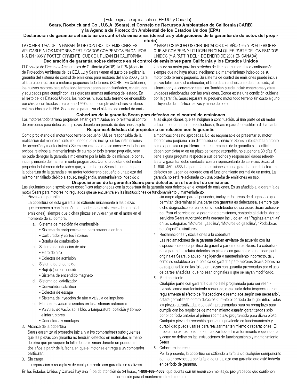
(Esta p_.ginase aplica s61oen EE.UU. y Canada.).
Sears, Roebuck and Co., U.S.A. (Sears), el Consejo de Recursos Arnbientales de California (CARB)
y la Agencia de Protecci6n Ambiental de los Estados Unidos (EPA)
Declaraci6n de garantia del sistema de control de emisiones (derechos y obligaciones de la garantia de defectos del propi=
etario)
LA COBERTURADELA GARANTJADE CONTROLDE EMISIONESES Y PARALOSMODELOSCERTIFICADOSDELANO 1997YPOSTERIORES,
APLICABLEA LOS MOTORESCERTIFICADOSCOMPRADOSENCALIFOR-
NIA EN1995YPOSTERIORMENTE,QUESE UTILIZANENCALIFORNIA,
Declaraci6n de garantJa sobre defectos en el control
ElConsejode RecursosAmbientalesde California(CARB),la EPA(Agencia
de Protecci6nAmbientalde los EE.UU.)y Searstienen elgustode explicarla
garantiadel sistemade control de emisionespara motoresdel a_o2000y para
elfuturocon relaci6na motorespeque_ostodo terreno(SORE).En California,
losnuevosmotorespeque6ostodo terrenodebenestar dise_ados,construidos
y equipadosparacumplircon las rigurosasnormasanti-smogdel estado.En
el restode losEstadosUnidos,losmotoresnuevostodoterrenode encendido
porchispa certificadosparael a_o 1997debencumplirest_ndaressimilares
establecidospot la EPA.Searsdebegarantizarel sistemade controlde emis-
QUESE COMPRENYUTILICENENCUALQUIERPARTEDELOS ESTADOS
UNIDOS(Y A PARTIRDEL 1 DEENERODE 2001 ENCANADA).
de ernisiones para California y los Estados Unidos
ionesdesu motorparalosperiodosde tiempoenumeradosa continuaci6n,
siemprequeno hayaabuso,negligenciao mantenimientoindebidode su
motortodoterrenopeque_o.Su sistemade controlde emisionespuedeincluir
piezastales comoel carburador,el filtrode aire,el sistemade encendido,el
silenciadoryel conversorcatalitico.Tambienpuedeincluirconectoresy otras
unidadesrelacionadascon las emisiones.Dondeexistaunacondici6ncubierta
porla garantia,Sears reparar_su peque6omotortodo terrenosin costoalguno
incluyendodiagn6stico,piezasy manode obra
Cobertura de la garantJa Sears para defectos en el control de ernJsiones
Los motorestodo terrenopeque6osest_ngarantizadosen Iorelativoal control alas disposicionesque se indiquena continuaci6n.Si una partedesu motor
de emisionespara defectosen piezasduranteunperiodode dos a_os,sujeto cubiertapot la garanfiaesdefectuosa,Sears reparar_o sustituir_dichaparte.
ResponsabJlidades del propietario en relacibn con la garantia
Comopropietariodel motortodo terrenopeque_o,Ud.es responsablede la
realizaci6ndel mantenimientorequeridoquese incluyeen las instrucciones
de operaci6ny mantenimiento.Searsrecomiendaquese conserventodoslos
recibosrelativosal mantenimientode su motortodoterrenopeque_o,pero
no pudedenegarla garantiasimplementeporla faltade losmismos,o porsu
incumplimientodel mantenimientoprogramatic.Comopropietariodel motor
peque_otodoterrenodebe saberque, sinembargo,Searsle puedenegar
la coberturade la garantiasi su motortodoterrenopeque6oo una piezadel
mismohanfalladodebido a abuso,negligencia,mantenimientoindebidoo
a modificacionesno aprobadas.Ud.es responsablede presentarsu motor
todoterrenopeque6oa un distribuidorde serviciosSearsautorizadotan pronto
comoaparezcaun problema.Las reparacionesde la garantiasinconfiicto
debencompletarseen un plazode tiempo razonable,no superiora 30 dias.Si
tienealguna preguntarespectoa sus derechosy responsabilidadesreferen-
tes a lagarantia,debe contactarcon un representantede serviciosSearsal
1--800--469--4663.La garantiade emisioneses unagarantiapordefectos.Los
defectossejuzgan de acuerdoconel funcionamientonormalde un motor.La
garantia noest_ relacionadacon unapruebade emisionesen uso.
DisposicJones de la garantJa Sears para defectos en el control de emJsiones
Las siguientesson disposicionesespecificasrelacionadascon la coberturade lagarantiaparadefectosen el controlde emisiones.Es un a_adidoa lagarantiade
motorSearspara motoresno reguladosque seencuentraen lasinstruccionesde funcionamientoy mantenimiento.
1. Piezascon garantia
La coberturade estagarantiase extiendeL]nicamentealas piezas
queaparecena continuaci6n(las partesde lossistemasde control de
emisiones),siempreque dichas piezasestuvieranya en el motoren el
momentode su compra.
a. Sistemade medici6nde combustible
• Sistemade enriquecimientopara arranqueen frio
• Carburadory partesinternas
• Bombadecombustible
b. Sistemade inducci6nde aire
• Filtrode aire
• Colectorde admisi6n
c. Sistemadeencendido
• Bujia(s) de encendido
• Sistemade encendidomagneto
d. Sistemadelcatalizador
• Convertidorcatalitico
• Colectorde escape
• Sistemade inyecci6nde aire o v_lvula de impulsos
e. Elementosvariados usadosen los sistemasanteriores
• Wlvulas de vacio, sensiblesa temperatura,posici6ny tiempo
e interruptores
• Conectoresy montajes
2. AIcancede la cobertura
Searsgarantizaal poseedorinicial y a loscompradoressubsiguientes
que laspiezascon garantiano tendr_n defectosen materialesni mano
de obra que provoquenla falla de las mismasduranteunperiodo de
dos a6osa partirde la fechaen queel motorse entregaa un comprador
particular.
3. Sin cargo
La reparaci6no reemplazode cualquierpartecongarantia se realizar_
sin cargo alguno parael poseedor,incluyendotareasde diagn6sticoque
permitandeterminarsi una partecon garantiaes defectuosa,siempreque
dichodiagn6sticose realiceen un distribuidorde serviciosSears autoriza-
do. Parael serviciode lagarantia de emisiones,contacteal distribuidorde
serviciosSearsautorizadom_s cercanoincluidoen las"P_ginasamarillas"
en lascategorias"Motores,gasolina","Motoresde gasolina","Podadoras
de cesped",o similares.
4. Reclamacionesy exclusionesa la cobertura
Las reclamacionesde lagarantia debenenviarsede acuerdo con las
disposicionesde la politica de garantia para motoresSears. La cobertura
de la garantiaexcluir_defectosenpiezascongarantiaque no scan partes
originalesSears,o abuso, negligenciao mantenimientoincorrecto,tal y
como se estableceenla politica de garantia para motoresSears.Sears no
es responsablede lasfallas en piezascongarantia provocadaspor el uso
de partesaSadidas,que no scan originaleso quese hayan modificado.
5. Mantenimiento
Cualquierpartecon garantiaque no este programadaparaserreem-
plazadacomomantenimientorequerido,o que s61odeba inspeccionarse
regularmenteal efectode "inspeccioneo reemplacesegL]nsea necesario",
estar_garantizadacontradefectosduranteel periodode la garantia.Todas
laspiezasgarantizadasque esten programadaspara su reemplazopara
cumplircon los requisitosde mantenimientoestar_ngarantizadass61o
porel periodoanterior al primerreemplazoprogramatic paradicha pieza.
Cualquierpiezade recambioqueseaequivalenteen funcionamientoy
durabilidadpuedeusarse para realizarmantenimientoo reparaciones.El
propietarioes responsablede realizartodo elmantenimientorequerido,tal
y comose define en las instruccionesde funcionamientoy mantenimiento
Sears
6. Coberturaindirecta
Porla presente,la coberturase extiendea lafalla de cualquiercomponente
de motorprovocadapor lafalla de unapieza con garantia queeste todavia
en periodode garantia.
En los EstadosUnidosy Canad_hayuna linea de atenci6nde 24 horas,1-800-469--4663,quecuentacon un menL]con mensajespre-grabadosque contienen
informaci6nparael mantenimientode motores.
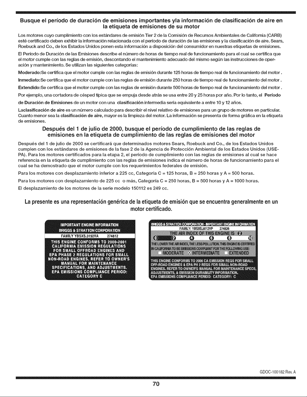
Busque el periodo de duraci6n de emisiones importantes yla informaci6n de clasificaci6n de aire en
la etiqueta de emisiones de su motor
Los motores cuyo cumpiimiento con los estAndares de emisi6n Tier 2 de la Comisi6n de Recursos Ambientales de California (CARB)
est6 certificado deben exhibir la informaci6n relacionada con el perJodo de duraci6n de las emisiones y la clasificaci6n de aire. Sears,
Roebuck and Co., de los Estados Unidos ponen esta informaci6n a disposici6n deJ consumidor en nuestras etiquetas de emisiones.
El Periodo de Duraci6n de las Emisiones describe el nQmero de horas de tiempo real de funcionamiento para el cual se certifica que
el motor cumple con las reglas de emisi6n, descontando el mantenimiento adecuado deJ mismo segQn las instrucciones de oper-
aci6n y mantenimiento. Se utilizan las siguientes categorias:
Moderado:Se certifica que el motor cumpie con las reglas de emisi6n durante 125 horas de tiempo real de funcionamiento deJmotor.
Inmediato:Se certifica que el motor cumple con las reglas de emisi6n durante 250 horas de tiempo real de funcionamiento deJ motor.
Extendido:Se certifica que el motor cumple con las reglas de emisi6n durante 500 horas de tiempo real de funcionamiento deJ motor.
Por ejemplo, una cortadora de c6sped tJpica que se empuja desde atrAs se usa entre 20 y 25 horas por afio. Por Io tanto, el Periodo
de Duraci6n de Emisiones de un motor con una clasificaci6n intermedia seria equivalente a entre 10 y 12 afios.
Laclasificaci6n de aJre es un nQmero calculado para describir eJnivel reiativo de emisiones para un grupo de motores en particular.
Cuanto menor sea Jaclasificaci6n de aire, mayor es JaJimpieza deJ motor. La informaci6n se presenta de forma gr&fica en Jaetiqueta
de emisiones.
Despu_s del 1 de julio de 2000, busque el periodo de cumplimiento de las reglas de
emisiones en la etiqueta de cumplimiento de las reglas de emisiones del motor
Despu_s deJ 1 de julio de 2000 se certificar_, que determinados motores Sears, Roebuck and Co., de los Estados Unidos
cumpien con los estAndares de emisiones de la fase 2 de la Agencia de Protecci6n Ambiental de los Estados Unidos (USE-
PA). Para los motores certificados para la etapa 2, el periodo de cumpiimiento con las reglas de emisiones al cual se hace
referencia en la etiqueta de cumpiimiento con las reglas de emisiones indica el nQmero de horas de funcionamiento para el
cuaJ se ha demostrado que el motor cumpie con los requerimientos federales de emisi6n.
Para los motores con desplazamiento inferior a 225 cc, Categoria C = 125 horas, B = 250 horas y A = 500 horas.
Para los motores con desplazamiento de 225 cc o mAs, Categoria C = 250 horas, B = 500 horas y A = 1000 horas.
El despiazamiento de los motores de la serie modelo 150112 es 249 cc.
La presente es una representaci6n gen_rica de la etiqueta de emisi6n que se encuentra generaimente en un
motor certificado.
FAMILYYBSXS.3192VA 274812
GDOC-100182Rev.A
70
Felicitacionespor haberrealizadouna adquisici6ninteligente.El
productoCraftsman@queha adquiridoest_ dise_adoy fabricado
parabrindarrnuchosa_osde funcionarnientoconfiable.Perocorno
todoslos productosa vecespuederequerirde reparaciones.Esen
esernornentocuandoel disponerde unAcuerdode protecci6npara
reparacionesle puedeahorrardineroy problernas.
A continuaci6nsedetallanlos puntosincluidosenel Acuerdo:
• Servicio experto prestadopornuestros10,000especialistasen
reparacionesprofesionales
• Servicio ilirnitadosincargoparalaspiezasy la rnanodeobraen
todaslas reparacionescubiertas
• Reernplazodel productohasta1500d61aressi no es posible
repararel productocubierto
• Descuentode 10%del precionormaldel servicioy delas piezas
relacionadascon el rnisrnoque no est_ncubiertasporel acuerdo;
adern&s,10%del precionormalde la verificaci6nde rnanten-
irnientopreventivo
• Ayudar_pidapottel_fono- IoIlarnarnosResoluci6nR_pida- el
apoyotelef6nicode un Charnuscaal representante.Pienseen
nosotroscornoel manual"de undue_ohablador."
Unavezadquiridoel Acuerdo,puedeprograrnarel serviciocon
tan s61orealizarunaIlarnadatelef6nica.PuedeIlarnaren cualquier
mornentodeldia o de la nocheo prograrnarun servicioen linea.
ElAcuerdode Protecci6nde Reparaci6nes una cornprasin riesgo.
Siustedanulaporalgunaraz6nduranteel periodode garantiade
producto,proporcionarernosun reernbolsoIleno.O,un reernbolso
prorrateadoencualquiermornentodespu_sdelperiodode garantia
de productoexpira, iAdquieraboysu acuerdode protecci6npara
reparaciones!
Seaplican deterrninadaslimitaciones y exclusiones.Paraobtener
inforrnaci6nadicional y preciosen los Estados UnidosIlarne al
1-800-827-6655.
El*Coverage en Canad_variaen algunosarticulos. Paradetalles
Ilenosla IlarnadaCharnuscaCanad_en 1-800-361-6665.
Servicio de instalaci6nde Sears
Sideseasolicitarla instalaci6nprofesionalde Searsde aparatos
dorn_sticos,dispositivosparaabrirportones,calentadoresde agua
y otrosarficulosdorn_sticosirnportantes,en los EstadosUnidoso
Canad_Ilarneal 1-800-4-MY-HOME®.
71

Your Home
For expert troubleshooting and home solutions advice:
www.managemyhome.com
For repair - in your home - of all major brand appliances,
lawn and garden equipment, or heating and cooling systems,
no matter who made it, no matter who sold it!
For the replacement parts, accessories and
owner's manuals that you need to do-it-yourself.
For Sears professional installation of home appliances
and items like garage door openers and water heaters.
1-800-4-MY-HOME ® (1-800-469-4663)
Call anytime, day or night (U.S.A. and Canada)
www.sears.com www.sears.ca
Our Home
For repair of carry-in items like vacuums, lawn equipment,
and electronics, call anytime for the location of your nearest
Sears Parts & Repair Service Center
1-800-488-1222 (U.S.A.) 1-800-469-4663 (Canada)
www.sears.com www.sears.ca
To purchase a protection agreement on a product serviced by Sears:
1-800-827-6655 (U.S.A.) 1-800-361-6665 (Canada)
Para pedir servicio de reparaci6n
a domicilio, y para ordenar piezas:
1-888-SU-HOGAR ®
(1-888-784-6427)
Au Canada pour service en fran£ais:
1-800-LE-FOYER M°
(1-800-533-6937)
www.sears.ca
® Registered Trademark / TMTrademark / SM Service Mark of Sears Brands, LLC
SM
® Marca Registrada / TMMarca de F&brica / Marca de Servicio de Sears Brands, LLC
MCMarque de commerce / MDMarque depos6e de Sears Brands, LLC © Sears Brands, LLC