Operator's Manual
P R 0 F E S S I 0 N A L
45" SNOW THROWER
Model No. 247.88846
CAUTION: Before using
this product, read this
manual and follow all
safety rules and operating
instructions.
, SAFETY
, ASSEMBLY
, OPERATION
, MAINTENANCE
, PARTS LIST
o ESPArqOL
Sears, Roebuck and Co., Hoffman Estates, IL 60179, U.S.A.
Visit our website: www.craftsman.com FORMNO.769-04981
6/15/2009
WarrantyStatement..................................Page2
SafeOperation Practices .......................... Pages 3-6
Safety Labels ............................................ Page 7
Assembly .................................................. Pages 8-12
Operation .................................................. Pages 13-16
Service and Maintenance ......................... Pages 17-24
Off-Season Storage .................................. Page 25
Troubleshooting ........................................ Page 26
Parts List ................................................... Page 28-40
Repair Protection Agreement ................... Page 45
Espa_ol ..................................................... Page 46
Service Numbers ...................................... Back Cover
CRAFTSMAN PROFESSIONAL FULL WARRANTY
Whenoperatedand maintainedaccordingto allsuppliedinstructions,ifthis CraftsmanProfessionalsnowthrowerfailsdue to a defectinmaterial
orworkmanshipwithintwoyearsfromthe dateof purchase,call 1-800-4-MY-HOME(1-800-469-4663)to arrangefor freein-homerepair(or
replacementifrepair provesimpossible).
Thiswarrantyappliesfor onlyone yearfromthe dateof purchaseifthis productiseverusedfor commercialor rentalpurposes.
ThiswarrantycoversONLYdefectsin materialandworkmanship.Searswill NOTpayfor:
• Expendableitemsthatbecomewornduringnormaluse,includingbutnot limitedto auger bladesor paddles,drift cutters,skid shoes,
shaveplate,shearpins,sparkplug,air cleaner,belts,andoil filter.
• Standardmaintenanceservicing,oil changes,or tune-ups.
• Tire replacementor repaircausedby puncturesfromoutsideobjects,suchas nails,thorns,stumps,or glass.
• Tireor wheelreplacementor repairresultingfromnormalwear,accident,or improperoperationor maintenance.
• Repairsnecessarybecauseof operatorabuse, includingbutnot limitedto damagecausedby over-speedingthe engine,or from
impactingobjectsthat bend the frame,augershaft,etc.
• Repairsnecessarybecauseof operatornegligence,includingbut not limitedto,electricalandmechanical
damagecausedby improperstorage,failureto usethe propergradeand amountof engineoil, or failureto maintainthe equipment
accordingto the instructionscontainedinthe operator'smanual.
• Engine(fuelsystem)cleaningor repairscausedbyfuel determinedto be contaminatedor oxidized(stale).In
general,fuel shouldbe usedwithin30 daysof itspurchasedate.
• Normaldeteriorationandwearof the exteriorfinishes,or productlabel replacement.
Thiswarrantyappliesonly whilethisproductiswithinthe UnitedStates.
Thiswarrantygivesyou specificlegal rights,andyou mayalso haveotherrightswhichvaryfromstateto state.
Sears, Roebuck and Co., Hoffman Estates, IL 60179
EngineOilCapacity: 37ounces
FuelCapacity: Approx.5 Quarts
SparkPlug: TorchF6RTC(951-10292)
SparkPlugGap: .020"to .030"
Serial Number .................................................................
Dateof Purchase.............................................................
Recordthe modelnumber,serialnumber
anddateof purchaseabove
© Sears Brands,LLC
2
Thissymbolpointsout importantsafetyinstructionswhich,if not
followed,couldendangerthepersonalsafetyand/orpropertyof
yourselfand others. Readandfollowall instructionsin this manual
beforeattemptingto operatethismachine.Failureto complywith
theseinstructionsmay resultin personalinjury.Whenyou seethis
symbol,HEEDITSWARNING!
CALIFORNIA PROPOSITION 65
EngineExhaust,someof itsconstituents,and certainvehicle
componentscontainoremitchemicalsknownto Stateof California
to causecancerandbirthdefectsorotherreproductiveharm,
Thismachinewasbuiltto beoperatedaccordingto the safeopera-
tion practicesinthis manual.As with anytype of powerequipment,
carelessnessor error on the partof the operatorcan resultin serious
injury.Thismachineis capableof amputatingfingers,hands,toes
andfeetandthrowingdebris.Failureto observethe followingsafety
instructionscouldresultin seriousinjuryor death.
Your Responsibility--Restrict the useof this powermachineto
personswho read,understandandfollowthewarningsand instruc-
tionsin this manualandon the machine,
SAVE THESE INSTRUCTIONS!
TRAiNiNG
• Read,understand,andfollowall instructionson the machineand
in themanual(s)beforeattemptingto assembleand operate.
Failureto do socan resultinseriousinjuryto the operatorand/
orbystanders.Keepthis manualin a safeplaceforfutureand
regularreferenceandfor orderingreplacementparts. Forques-
tionscall,1-800-4MY-HOME.
• Befamiliarwithall controlsandtheir properoperation.Knowhow
to stopthe machineanddisengagethemquickly.
Neverallowchildrenunder 14 yearsof age to operatethis
machine.Children14andover shouldreadandunderstandthe
instructionsand safe operationpracticesin this manualandon
the machineandbe trainedandsupervisedby an adult.
Neverallowadultsto operatethis machinewithoutproper
instruction.
• Thrownobjectscan causeseriouspersonalinjury. Planyour
snow-throwingpatternto avoiddischargeof materialtoward
roads,bystandersandthe like.
Keepbystanders,pets and childrenat least75feetfromthe
machinewhile itisinoperation.Stopmachineifanyoneenters
the area.
Exercisecautionto avoidslippingor falling,especiallywhen
operatingin reverse.
PREPARATION
Thoroughlyinspecttheareawherethe equipmentis to beused.
Removeall doormats,newspapers,sleds,boards,wiresandother
foreignobjects,whichcouldbe trippedoveror thrownby the auger/
impeller.
Alwayswear safetyglassesor eyeshieldsduringoperationand
while performingan adjustmentor repairto protectyoureyes.
Thrownobjectswhichricochetcancause seriousinjuryto the
eyes.
Donot operatewithoutwearingadequatewinteroutergarments.
Donot wearjewelry,long scarvesor otherlooseclothing,which
could becomeentangledin movingparts.Wearfootwearwhich
will improvefootingonslipperysurfaces.
Usea groundedthree-wireextensioncordand receptaclefor all
machineswith electricstartengines.
Disengageall controlleversbeforestartingthe engine.
Adjustcollectorhousingheightto cleargravelorcrushedrock
surfaces.
Neverattemptto makeanyadjustmentswhileengineis running,
exceptwherespecificallyrecommendedinthe operator'smanual.
Letengineandmachineadjustto outdoortemperaturebefore
startingto clearsnow.
3
Safe Handling of Gasoline
Toavoidpersonalinjuryor propertydamageuseextremecare in
handlinggasoline.Gasolineis extremelyflammableandthe vaporsare
explosive.Seriouspersonalinjurycan occurwhengasolineis spilled
onyourselfor yourclotheswhichcan ignite.Washyour skin and
changeclothesimmediately.
• Useonly an approvedgasolinecontainer.
• Extinguishall cigarettes,cigars,pipesandother sources
of ignition.
• Neverfuelmachineindoors.
• Neverremovegas capor addfuel whilethe engineis hot
or running.
• Allowengineto coolat leasttwo minutesbeforerefueling.
• Neveroverfill fueltank. Filltank to no morethan1/2inch
belowbottomof filler neckto providespacefor fuel
expansion.
• Replacegasolinecap andtightensecurely.
• If gasolineis spilled,wipeit off the engineand equipment.
Movemachineto anotherarea.Wait5 minutesbefore
startingthe engine.
• Neverstorethe machineor fuel containerinsidewhere
thereis anopenflame,sparkor pilotlight (e.g.furnace,
waterheater,spaceheater,clothesdryer etc.).
• Allowmachineto cool at least5 minutesbeforestoring.
• Neverfill containersinsidea vehicleor ona truckor trailer
bedwitha plasticliner.Alwaysplacecontainersonthe
groundawayfromyourvehiclebeforefilling.
• If possible,removegas-poweredequipmentfrom thetruck
ortrailerand refuelit on the ground.If this is not possible,
then refuelsuch equipmenton a trailerwitha portable
container,ratherthan fromagasolinedispensernozzle.
• Keepthe nozzlein contactwith the rimof the fueltank or
containeropeningat alltimesuntil fuelingis complete.Do
notuse a nozzlelock-opendevice.
OPERATION
• Do not puthandsorfeetnear rotatingparts,in the auger/impeller
housingor chuteassembly.Contactwith the rotatingpartscan
amputatehandsandfeet.
• Theauger/impellercontrolleveris a safetydevice.Neverbypass
itsoperation.Doingso makesthe machineunsafeand may cause
personalinjury.
• Thecontrolleversmustoperateeasilyin bothdirectionsand
automaticallyreturnto the disengagedpositionwhenreleased.
• Neveroperatewith a missingor damagedchuteassembly.Keep
all safetydevicesin placeand working.
• Neverrunanengineindoorsor ina poorlyventilatedarea. Engine
exhaustcontainscarbonmonoxide,an odorlessanddeadlygas.
• Do notoperatemachinewhileunderthe influenceof alcoholor
drugs.
• Mufflerand engine becomehotandcan causea burn.Do not
touch.Keepchildrenaway.
• Exerciseextremecautionwhenoperatingon or crossinggravel
surfaces.Stay alertfor hidden hazardsor traffic.
• Exercisecautionwhenchangingdirectionand whileoperatingon
slopes.
• Planyoursnow-throwingpatternto avoiddischargetowards
windows,walls,carsetc. Thus,avoidingpossibleproperty
damageor personalinjurycausedby a ricochet.
• Neverdirect dischargeat children,bystandersand petsor allow
anyoneinfrontof the machine.
• Donot overloadmachinecapacityby attemptingto clearsnowat
too fastof a rate.
• Neveroperatethis machinewithoutgoodvisibility or light. Always
be sureof yourfootingand keepa firmholdon the handles.Walk,
neverrun.
• Disengagepowerto theauger/impellerwhentransportingor not
in use.
• Neveroperatemachineat high transportspeedson slippery
surfaces.Lookdownand behindand usecare whenbackingup.
• If the machineshouldstart to vibrateabnormally,stopthe engine,
disconnectthe sparkplugwire andgroundit againstthe engine.
Inspectthoroughlyfor damage.Repairanydamagebefore
startingandoperating.
• Disengageall controlleversandstopenginebeforeyouleave
the operatingposition(behindthe handles).Wait untilthe auger/
impellercomesto a completestop beforeuncloggingthechute
assembly,makingany adjustments,or inspections.
• Neverput yourhand in the dischargeor collectoropenings.Do
not unclogchuteassemblywhileengineis running.Shutoff
engineand remainbehindhandlesuntilall movingparts have
stoppedbeforeunclogging.
• Useonly attachmentsand accessoriesapprovedby the manufac-
turer (e.g.wheelweights,tire chains,cabsetc.).
• Whenstartingengine,pull cord slowlyuntilresistanceis felt, then
pull rapidly.Rapidretractionof startercord(kickback)will pull
handandarmtowardenginefasterthan youcan let go. Broken
bones,fractures,bruisesor sprainscould result.
• If situationsoccur whichare notcoveredinthis manual,use care
andgoodjudgment.ContactCustomerSupportfor assistance
andthe nameof your nearestservicingdealer.
CLEARING A CLOGGED DISCHARGE CHUTE
Handcontactwith the rotatingimpellerinsidethe dischargechute
is the mostcommoncauseof injuryassociatedwith snowthrowers.
Neveruse yourhandto cleanout thedischargechute.
Toclear thechute:
1. SHUTTHEENGINEOFF!
2. Wait 10secondsto be surethe impellerbladeshavestopped
rotating.
3. Alwaysusea clean-outtool,not yourhands.
4
MAINTENANCE & STORAGE
• Nevertamperwithsafetydevices.Checktheirproperoperation
regularly.Referto the maintenanceandadjustmentsectionsof
thismanual.
• Beforecleaning,repairing,or inspectingmachinedisengageall
controlleversandstopthe engine.Wait untilthe auger/impeller
cometo a completestop.Disconnectthe sparkplug wireand
groundagainsttheengineto preventunintendedstarting.
Checkboltsand screwsfor propertightnessat frequentintervals
to keepthe machineinsafeworkingcondition.Also, visually
inspectmachinefor anydamage.
Do notchangetheenginegovernorsettingor over-speedthe
engine.Thegovernorcontrolsthe maximumsafeoperatingspeed
of the engine.
Snowthrowershaveplatesand skid shoesare subjectto wear
anddamage.Foryoursafetyprotection,frequentlycheckall
componentsand replacewithoriginalequipmentmanufacturer's
(OEM)partsonly."Useof partswhichdo not meetthe original
equipmentspecificationsmayleadto improperperformanceand
compromisesafety!"
Checkcontrolleversperiodicallyto verifytheyengageanddisen-
gageproperlyand adjust,if necessary.Referto the adjustment
sectioninthisoperator'smanualfor instructions.
Maintainor replacesafetyand instructionlabels,as necessary.
• Observeproperdisposallawsand regulationsfor gas, oil,etc. to
protectthe environment.
Priorto storing,run machinea few minutestoclear snowfrom
machineand preventfreezeup of auger/impeller.
Neverstorethe machineorfuel containerinsidewherethereisan
openflame,spark or pilot lightsuch as a waterheater,furnace,
clothesdryer etc.
Alwaysreferto the operator'smanualfor properinstructionson
off-seasonstorage.
Checkfuelline,tank, cap,andfittingsfrequentlyfor cracksor
leaks.Replaceif necessary.
Do notcrankenginewithsparkplugremoved.
Accordingto the ConsumerProductsSafetyCommission(CPSC)
andthe U.S.EnvironmentalProtectionAgency(EPA),thisproduct
hasan AverageUsefulLifeof seven(7) years,or 60 hoursof
operation.At the endof theAverageUsefulLifehavethe machine
inspectedannuallybyan authorizedservicedealerto ensurethat
allmechanicaland safetysystemsare workingproperlyand not
wornexcessively.Failureto do so can resultinaccidents,injuries
ordeath.
DO NOT MODIFY ENGINE
Toavoidseriousinjuryor death,do not modifyengine in any way.
Tamperingwiththe governorsettingcanlead to a runawayengineand
causeit to operateat unsafespeeds.Nevertamperwithfactory setting
of enginegovernor.
NOTICE REGARDING EMiSSiONS
Engineswhich are certifiedtocomplywith Californiaand federal
EPAemissionregulationsfor SORE(SmallOff RoadEquipment)are
certifiedto operateon regularunleadedgasoline,and mayinclude
the followingemissioncontrol systems:EngineModification(EM),
OxidizingCatalyst(OC), SecondaryAir Injection(SAI)and ThreeWay
Catalyst(TWO)if so equipped.
SPARK ARRESTOR
Thismachineisequippedwithaninternalcombustionengineand
shouldnotbe usedon or nearany unimprovedforest-covered,
brush-coveredorgrass-coveredlandunlessthe engine'sexhaust
systemisequippedwith a sparkarrestermeetingapplicablelocalor
statelaws(if any)
Ifa sparkattester is used, it shouldbe maintainedin effectiveworking
orderby theoperator.Inthe Stateof Californiathe aboveis required
bylaw (Section4442of the CaliforniaPublicResourcesCode).Other
statesmayhavesimilarlaws. Federallawsapplyon federallands.
A spark arresterfor the muffleris availablethroughyournearestSears
PartsandRepairServiceCenter.
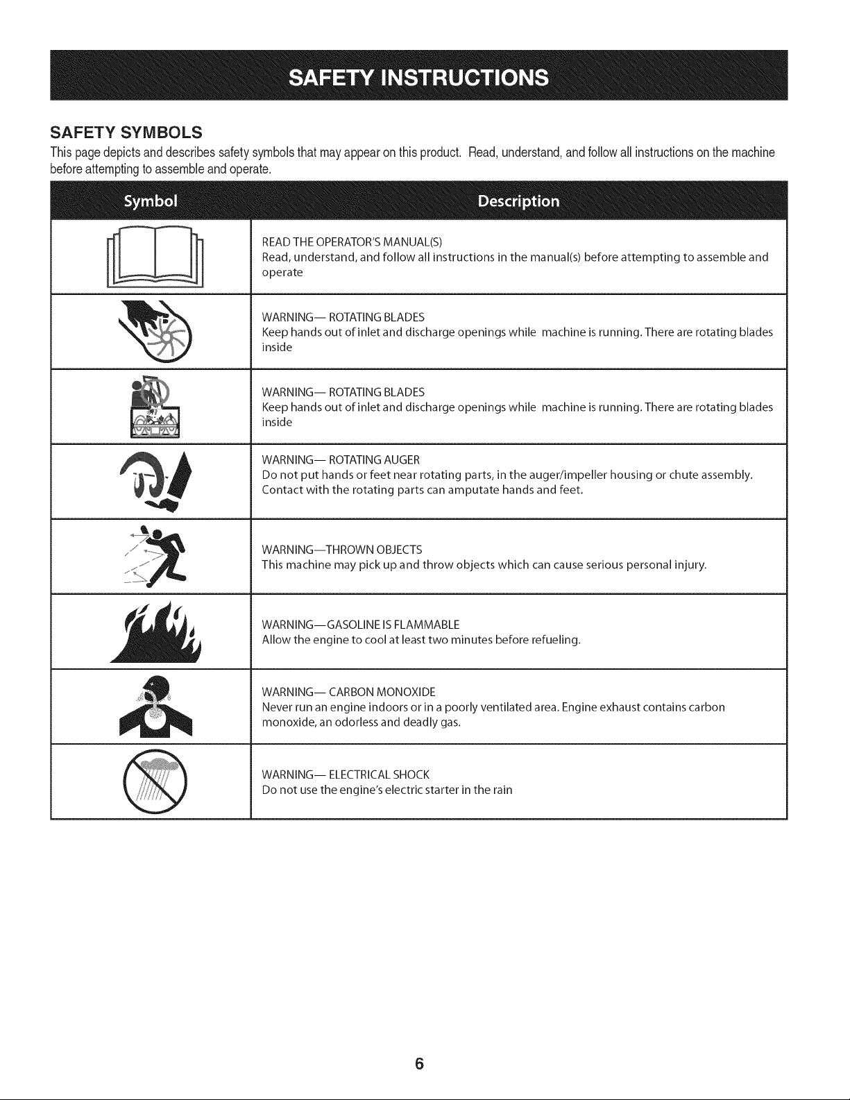
SAFETY SYMBOLS
Thispagedepictsanddescribessafetysymbolsthat mayappearonthisproduct. Read,understand,and followall instructionson the machine
beforeattemptingto assembleandoperate.
i
i
READ THE OPERATOR'S MANUAL(S)
Read, understand, and follow all instructions in the manual(s) before attempting to assemble and
operate
WARNING-- ROTATING BLADES
Keep hands out of inlet and discharge openings while machine is running. There are rotating blades
inside
WARNING-- ROTATING BLADES
Keep hands out of inlet and discharge openings while machine is running. There are rotating blades
inside
WARNING-- ROTATING AUGER
Do not put hands or feet near rotating parts, in the auger/impeller housing or chute assembly.
Contact with the rotating parts can amputate hands and feet.
WARNING--THROWN OBJECTS
This machine may pick up and throw objects which can cause serious personal injury.
WARNING--GASOLINE IS FLAMMABLE
Allow the engine to cool at least two minutes before refueling.
WARNING-- CARBON MONOXIDE
Never run an engine indoors or in a poorly ventilated area. Engine exhaust contains carbon
monoxide, an odorless and deadly gas.
WARNING-- ELECTRICAL SHOCK
Do not use the engine's electric starter in the rain
6
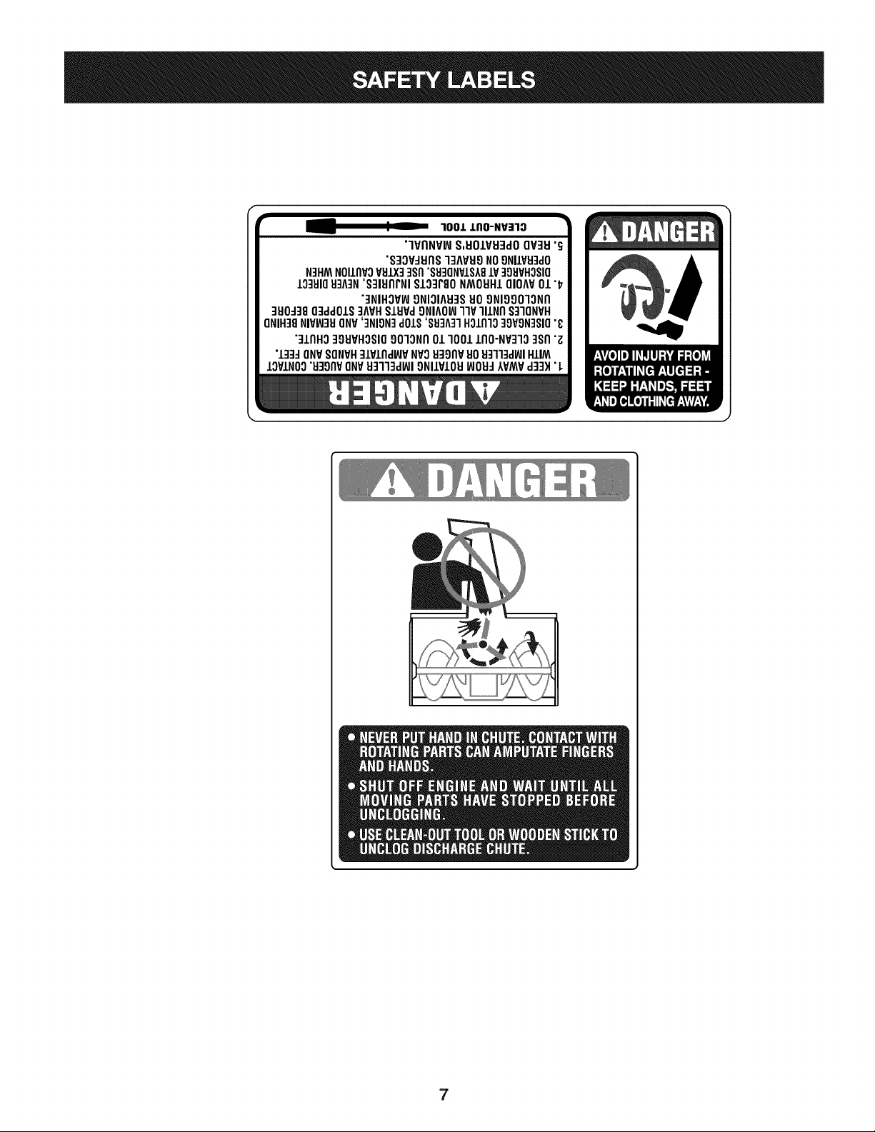
100JL J,IIO-NV=IlO
"'IVI1NVIAIS,EIOIVEI:IdOQV3EI"_
"S:IOV:IEI(1S"IqAVEI9NO9NIlVEIqdO
N]HMNOIII1VOVBIX]]SI1"SEI3ONVISA8IV ]gEIVHOSIO
10qBI0BLAIN'S:IIEIIlrNI$103r80 NMOEIHLQIOAV01 "17
"3NIHOVW9NIOIAB:ISBO9NIOOOlON[I
qElO-1:18O]ddOlS:IAVHSIEIVa£)NIAO_llP lllNI1 S:IIONVH
ONIH]8NIVW]BONV']NION]d01S'SB]A31H011110qOVgN]SIO"_
":llrlHO39EIVHOSIO9010NI101 1001 1[10-NV31038rl"z
•133JQNV8QNVH]lPllldBJP NVOEI3_)I1VBOB:lll:kl_l HIlM
IOVINO0"EI:IO[1VONVB::lll:ld_JIONIIVIOB_OB:I AVMVdq:lH•L
7
NOTE:Referencesto rightorleft sideof the snowthrowerare
determinedfromthe operatingpositionlookingforwardto the frontof
the machine.
REMOVING FROM CRATE
1. Removescrewsfromthe bottomof thecrate securingthesides,
andendsof the shippingcrate.
2. Lift off the topoff of the crate and set outof theway of the
assemblyarea.
3. Removeanddiscardplasticbagthatcoversunit.
4. Removeany loosepartsincludedwith unit (e.g.,Operator's
Manual,etc.).
5. Pushdownon the lowerhandleandpullunit backout of crate.
6. Makecertainthe crate has beencompletelyemptiedbefore
discardingit.
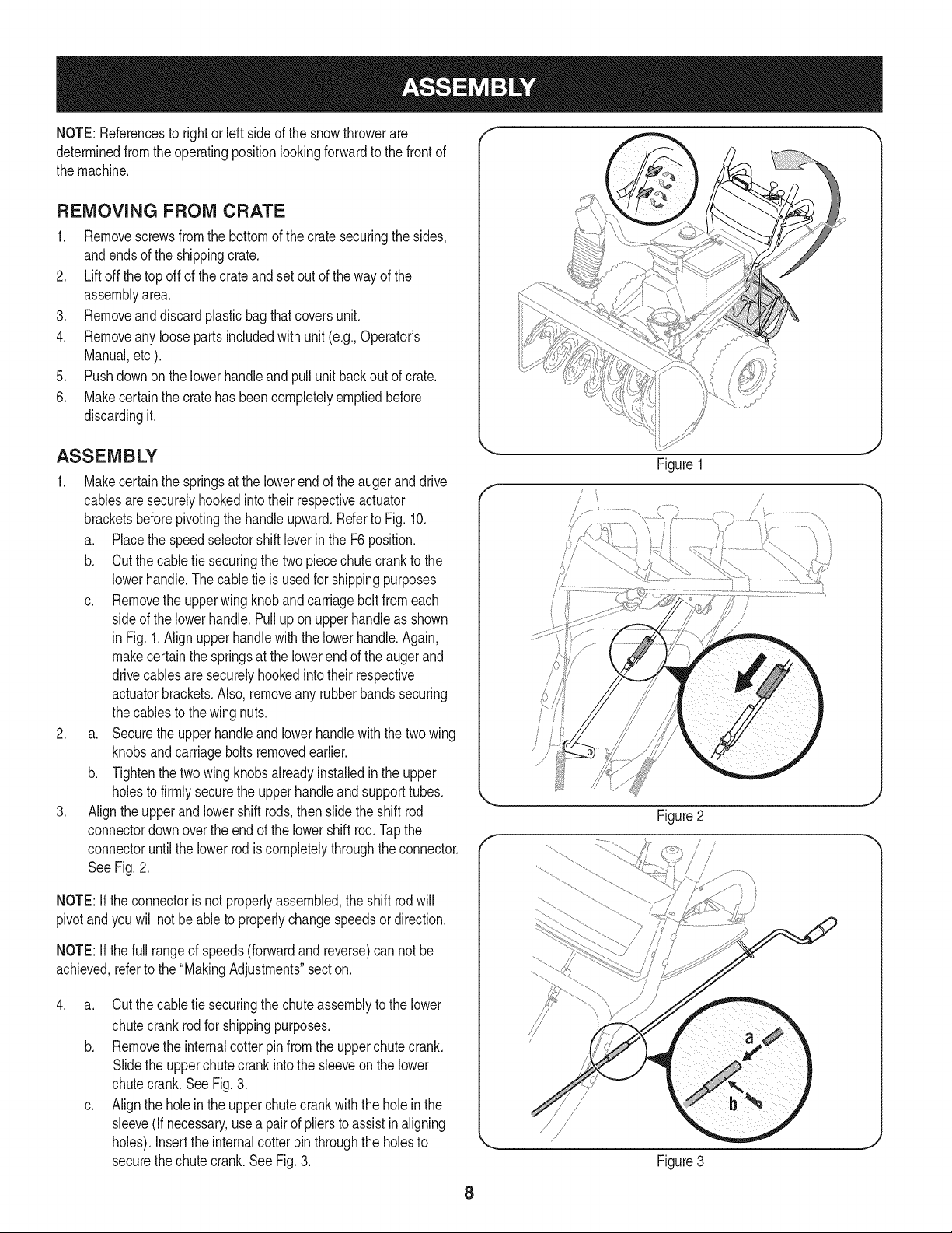
ASSEMBLY
1. Makecertainthe springsat the lowerend of the augerand drive
cablesaresecurelyhookedintotheir respectiveactuator
bracketsbeforepivotingthe handleupward.Referto Fig. 10.
a. Placethe speedselectorshiftleverin the F6 position.
b. Cut the cabletie securingthe two piecechute crank to the
lowerhandle.Thecable tie is usedfor shippingpurposes.
c. Removethe upperwingknobandcarriageboltfromeach
sideof the lowerhandle.Pulluponupperhandleas shown
in Fig. 1.Align upper handlewith the lowerhandle.Again,
makecertainthe springsat the lowerendof the augerand
drivecablesaresecurelyhookedintotheir respective
actuatorbrackets.Also,removeany rubberbandssecuring
thecablesto the wingnuts.
2. a. Securethe upperhandleandlowerhandlewiththetwo wing
knobsandcarriageboltsremovedearlier.
b. Tightenthetwo wingknobsalreadyinstalledin the upper
holesto firmlysecurethe upperhandleand supporttubes.
3. Align the upperand lowershift rods, thenslidethe shift rod
connectordownoverthe end of the lowershift rod.Tapthe
connectoruntilthe lower rodis completelythroughtheconnector.
See Fig.2.
NOTE:If theconnectoris notproperlyassembled,the shift rodwill
pivotand youwill notbe ableto properlychangespeedsor direction.
NOTE:If thefull rangeof speeds(forwardand reverse)can not be
achieved,referto the "MakingAdjustments"section.
.
a. Cut the cabletie securingthe chute assemblyto the lower
chutecrankrodfor shippingpurposes.
b. Removethe internalcotterpin from the upperchutecrank.
Slidethe upperchutecrankinto the sleeveon the lower
chutecrank.See Fig.3.
c. Alignthe holein the upperchutecrankwiththe holeinthe
sleeve(Ifnecessary,usea pairof pliersto assist in aligning
holes).Insertthe internalcotter pinthroughthe holesto
securethe chutecrank.SeeFig.3.
Y
Figure 1
/
J
Figure3
8
5. Removelocknutsandscrewssecuringoneof the flangekeepers
to the chuteassembly.
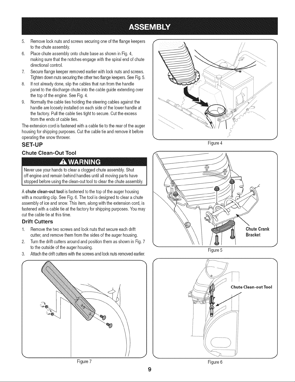
6. Placechuteassemblyonto chutebaseas shown in Fig. 4,
makingsurethatthe notchesengagewith the spiralend of chute
directionalcontrol.
7. Secureflangekeeperremovedearlierwithlocknutsandscrews.
Tightendownnutssecuringtheothertwoflangekeepers.SeeFig.5.
8. If notalreadydone,slipthe cablesthat runfromthe handle
panelto the dischargechuteintothe cableguideextendingover
the topof the engine.SeeFig.4.
9. Normallythecable tiesholdingthe steeringcablesagainstthe
handlearelooselyinstalledoneach sideof the lowerhandleat
the factory.Pullthe cableties tightto secure.Cut the excess
fromtheendsof cableties.
Theextensioncord is fastenedwitha cabletie to the rearof the auger
housingfor shippingpurposes.Cut thecabletie and removeit before
operatingthe snowthrower.
SET-UP
Chute Clean=Out Tool
Neveruse yourhandsto cleara cloggedchuteassembly.Shut
off engineand remainbehindhandlesuntilall movingpartshave
stoppedbeforeusingthe clean-outtoolto clearthechuteassembly.
Figure4
J
A chuteclean-outtool is fastenedto the top of theaugerhousing
witha mountingclip. See Fig. 6. Thetool is designedto clear achute
assemblyof ice andsnow.Thisitem,along with the extensioncord,is
fastenedwith a cable tie at the factoryfor shippingpurposes.Youmay
cutthe cabletie at thistime.
Drift Cutters
1. Removethetwo screwsand lock nutsthat secureeach drift
cutter,andremovethemfromthe sidesof the augerhousing.
2. Turnthe driftcuttersaroundandpositionthemas shownin Fig.7
to the outsideof the augerhousing.
3. Attachthedriftcutterswiththescrewsandlocknutsremovedearlier.
F-
ChuteCrank
Bracket
Figure5
J
f
Chute Clean=out Tool
Figure7
9
Figure6
J
Tire Pressure (Pneumatic Tires)
Underany circumstancedo notexceedmanufacturer'srecom-
mendedpsi. Equaltire pressureshouldbe maintainedat all times.
Excessivepressurewhen seatingbeadsmay causetire/rim
assemblyto burstwithforcesufficientto cause seriousinjury.Refer
to sidewallof tire for recommendedpressure.
The tirescan beover-inflatedfor shippingpurposes.Checkthe tire
pressurebeforeoperatingthe snowthrower. Referto the tire sidewall
for rnanufactures'srecommendedpsianddeflate(or inflate)thetires
as necessary.
NOTE:Equaltirepressureisto bemaintainedat alltimesfor perfor-
mancepurposes.
Fuel Recommendations
Useautomotivegasoline(unleadedor low leadedto minimizecombus-
tion chamberdeposits)witha minimumof 87 octane.Gasolinewith
upto 10%ethanolor 15%MTBE(MethylTertiaryButyl Ether)can be
used.Neverusean oil/gasolinemixtureordirty gasoline.Avoidgetting
dirt, dust,or waterinthe fuel tank.DO NOTuse E85gasoline.
• Refuelin a well-ventilatedareawiththe enginestopped.Do not
smokeor allowflamesor sparksinthe areawherethe engineis
refueledor wheregasolineis stored.
• Donot overfillthe fueltank. After refueling,makesurethe tank
cap is closedproperlyand securely.
• Be carefulnot to spillfuel whenrefueling.Spilledfuel or fuel vapor
mayignite.Ifany fuelis spilled,makesurethe areais dry before
startingthe engine.
• Avoidrepeatedor prolongedcontactwith skinor breathingof vapor.
Adding Fuel
Useextremecarewhenhandlinggasoline.Gasolineis extremely
flammableand the vaporsare explosive. Neverfuel the machine
indoorsor while the engineis hotor running.Extinguishcigarettes,
cigars,pipesandother sourcesof ignition.
usea pressurizedstartingfluid. Vaporsareflammable.
1. Cleanaroundfuel fill beforeremovingcap to fuel.
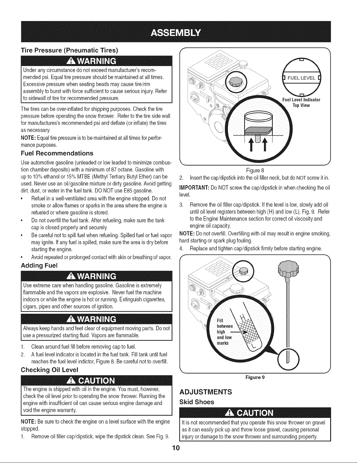
2. A fuel levelindicatoris locatedinthe fueltank. Fill tankuntilfuel
reachesthe fuel levelindictor,Figure8. Becarefulnotto overfill.
Checking Oil Level
The engineis shippedwithoilin the engine.Youmust,however,
checkthe oil levelprior to operatingthe snowthrower.Runningthe
enginewith insufficientoil cancause seriousengine damageand
[vo d the engne warranty.
NOTE:Be suretocheckthe engineon a levelsurfacewiththe engine
stopped.
1. Removeoil fillercap/dipstick,wipethe dipstickclean.SeeFig.9.
Fuel Level Indicator
TopView
Figure8
2. Insertthecap/dipstickintothe oilfillerneck,but do NOTscrewit in.
IMPORTANT:Do NOT screwthe cap/dipstickinwhencheckingthe oil
level.
3. Removethe oil filler cap/dipstick.If thelevelis low,slowlyadd oil
until oil levelregistersbetweenhigh(H) andlow (L), Fig.9. Refer
to the EngineMaintenancesectionfor correctoil viscosityand
engineoil capacity.
NOTE: Do notoverfill.Overfillingwithoilmayresultinenginesmoking,
hardstartingor sparkplug fouling.
4. Replaceandtightencap/dipstickfirmlybeforestartingengine.
Figure g
ADJUSTMENTS
Skid Shoes
it is not recommendedthatyouoperatethis snowthroweron gravel
as it caneasilypickupand throwloosegravel,causingpersonal
injuryordamageto the snowthrowerand surroundingproperty.
10
Thesnowthrowerskidshoesareadjustedupwardatthe factoryfor ship-
pingpurposes.Adjustthemdownwardpriorto operatingthe machine.
• Forclosesnowremovalona smoothsurface,raiseskidshoes
higheronthe augerhousing.
• Useamiddleor lowerpositionwhentheareato beclearedisuneven.
NOTE:Ifyou chooseto operatethe snowthroweron agravelsurface,
keepthe skidshoesin positionfor maximumclearancebetweenthe
groundandthe shaveplate.
Toadjustthe skidshoes:
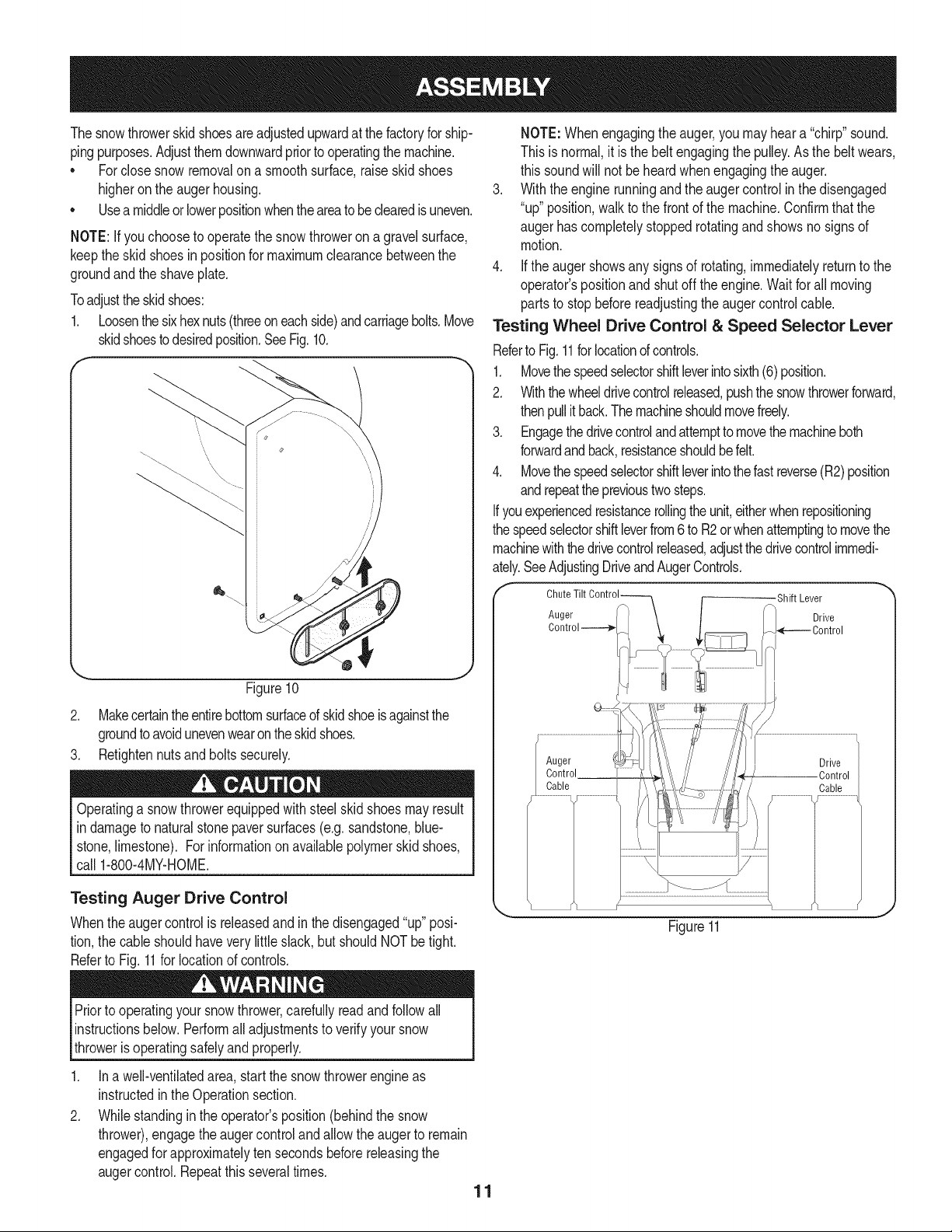
1. Loosenthesixhexnuts(threeoneachside)andcarriagebolts.Move
skidshoestodesiredposition.SeeFig.10.
Figure10
2. Makecertaintheentirebottomsurfaceof skidshoeisagainstthe
groundto avoidunevenwearontheskidshoes.
3. Retightennutsandboltssecurely.
Operatinga snowthrowerequippedwithsteelskidshoesmayresult
in damageto naturalstone paversurfaces(e.g.sandstone,blue-
stone,limestone).Forinformationon availablepolymerskid shoes,
call 1-800-4MY-HOME.
Testing Auger Drive Control
Whentheaugercontrolis releasedandin the disengaged"up"posi-
tion,the cableshouldhavevery little slack, but shouldNOTbe tight.
Referto Fig.11for locationof controls.
NOTE:Whenengagingthe auger,youmay hear a "chirp"sound.
Thisis normal,it isthe beltengagingthe pulley.As the beltwears,
this soundwill not beheardwhenengagingthe auger.
3. With the engine runningand the augercontrolin the disengaged
"up" position,walkto the frontof the machine.Confirmthat the
augerhascompletelystoppedrotatingandshowsno signsof
motion.
4. Ifthe augershowsany signsof rotating,immediatelyreturnto the
operator'spositionandshutoff theengine.Waitfor all moving
partsto stopbeforereadjustingthe augercontrolcable.
Testing Wheel Drive Control & Speed Selector Lever
Referto Fig.11forlocationofcontrols.
1. Movethe speedselectorshiftleverintosixth(6) position.
2. Withthewheeldrivecontrolreleased,pushthesnowthrowerforward,
thenpullit back.Themachineshouldmovefreely.
3. Engagethedrivecontrolandattemptto movethemachineboth
forwardandback,resistanceshouldbefelt.
4. Movethe speedselectorshiftleverintothefastreverse(R2)position
andrepeattheprevioustwo steps.
Ifyouexperiencedresistancerollingtheunit,eitherwhenrepositioning
the speedselectorshiftleverfrom6 to R2or whenattemptingto movethe
machinewiththedrivecontrolreleased,adjustthedrivecontrolimmedi-
ately.SeeAdjustingDriveandAugerControls.
Shift Lever
Drive
_(--.---- Control
Auger
Control
Cable
Drive
Control
Cable
Figure11
Priorto operatingyoursnowthrower,carefullyread and followall
instructionsbelow.Performall adjustmentsto verifyyoursnow
throweris operatingsafelyand properly.
.
2.
In a well-ventilatedarea,start the snowthrowerengineas
instructedin the Operationsection.
Whilestandinginthe operator'sposition(behindthe snow
thrower),engagethe augercontrol and allowtheaugerto remain
engagedfor approximatelyten secondsbeforereleasingthe
augercontrol.Repeatthis severaltimes.
11
Adjusting Wheel Drive & Auger Controls
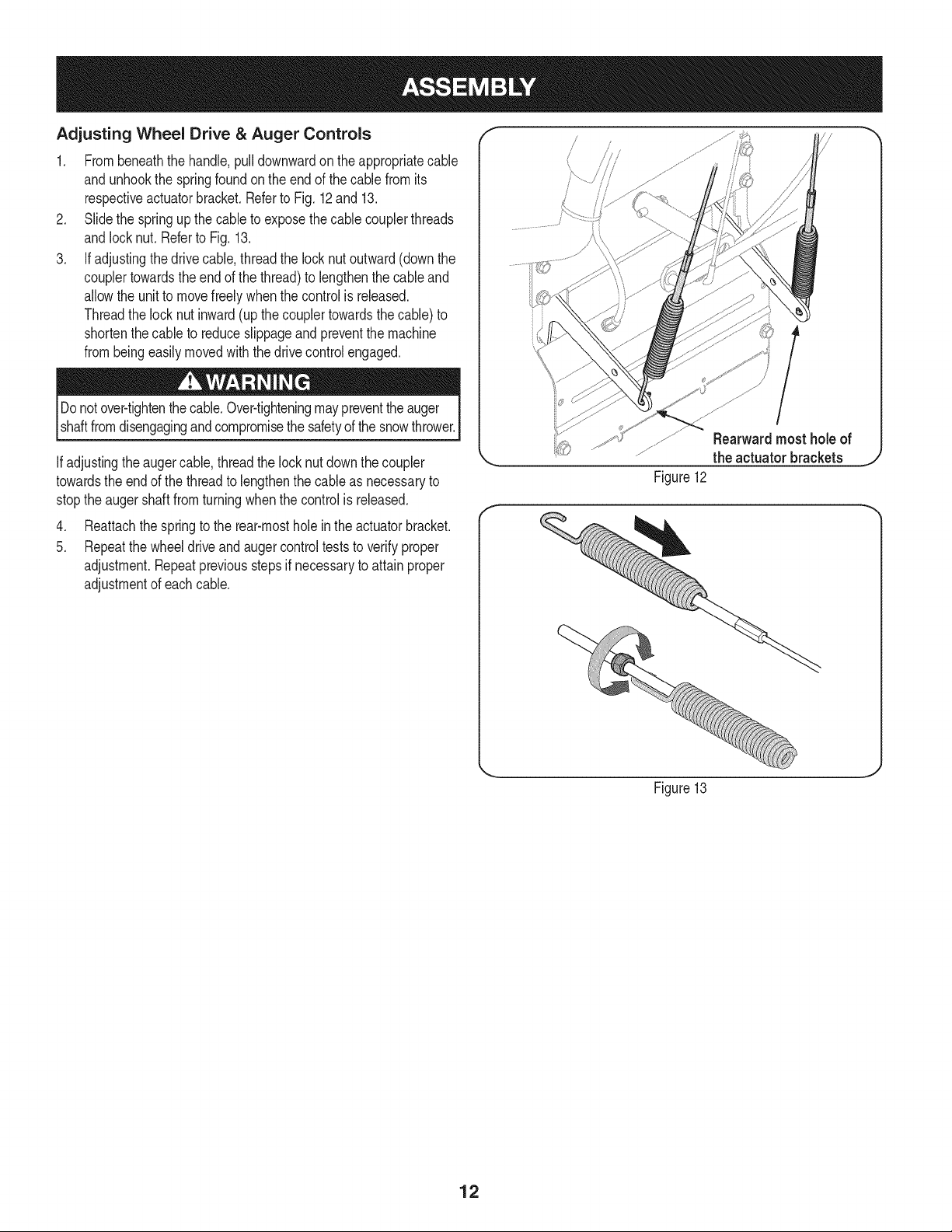
1. Frombeneaththe handle,pull downwardon the appropriatecable
andunhookthe springfoundon the end of the cablefrom its
respectiveactuatorbracket.Referto Fig. 12 and 13.
2. Slidethe springup thecable to exposethe cablecouplerthreads
andlocknut.Referto Fig.13.
3. If adjustingthe drivecable,threadthe lock nutoutward(downthe
couplertowardsthe endof the thread)to lengthenthecable and
allowthe unitto movefreelywhenthe controlis released.
Threadthe lock nut inward(up thecouplertowardsthecable) to
shortenthecable to reduceslippageand preventthe machine
frombeingeasilymovedwiththe drivecontrolengaged.
Donotover-tightenthe cable.Over-tighteningmaypreventtheauger
shaftfromdisengagingand compromisethe safetyof the snowthrower.
Ifadjustingthe augercable,threadthe locknut downthecoupler
towardsthe endof the threadto lengthenthe cableas necessaryto
stoptheaugershaftfromturningwhenthe control is released.
4. Reattachthe springto the rear-mostholein theactuatorbracket.
5. Repeatthewheeldriveandaugercontrolteststo verifyproper
adjustment.Repeatpreviousstepsif necessaryto attain proper
adjustmentof eachcable.
Rearwardmost holeof
the actuator brackets
Figure12
Figure13
J
12
f
SpeedSelector
ShiftLever
Drive Two-wayChuteControlTM
Headli<
ChuteAssembly
DriftCutters
Clean-out Tool_
SkidShoes
_!r'_Auger
Housing
_._-=-==AugerControl
Wheel Control
Steering
Control
Primer
Oil Filler
Cap/Dipstick
Key
Throttle
_L=-Gas Cap
Electric
Start
Button
Electric
Outlet
RecoilStarter
Handle
Figure
14
OilDrain
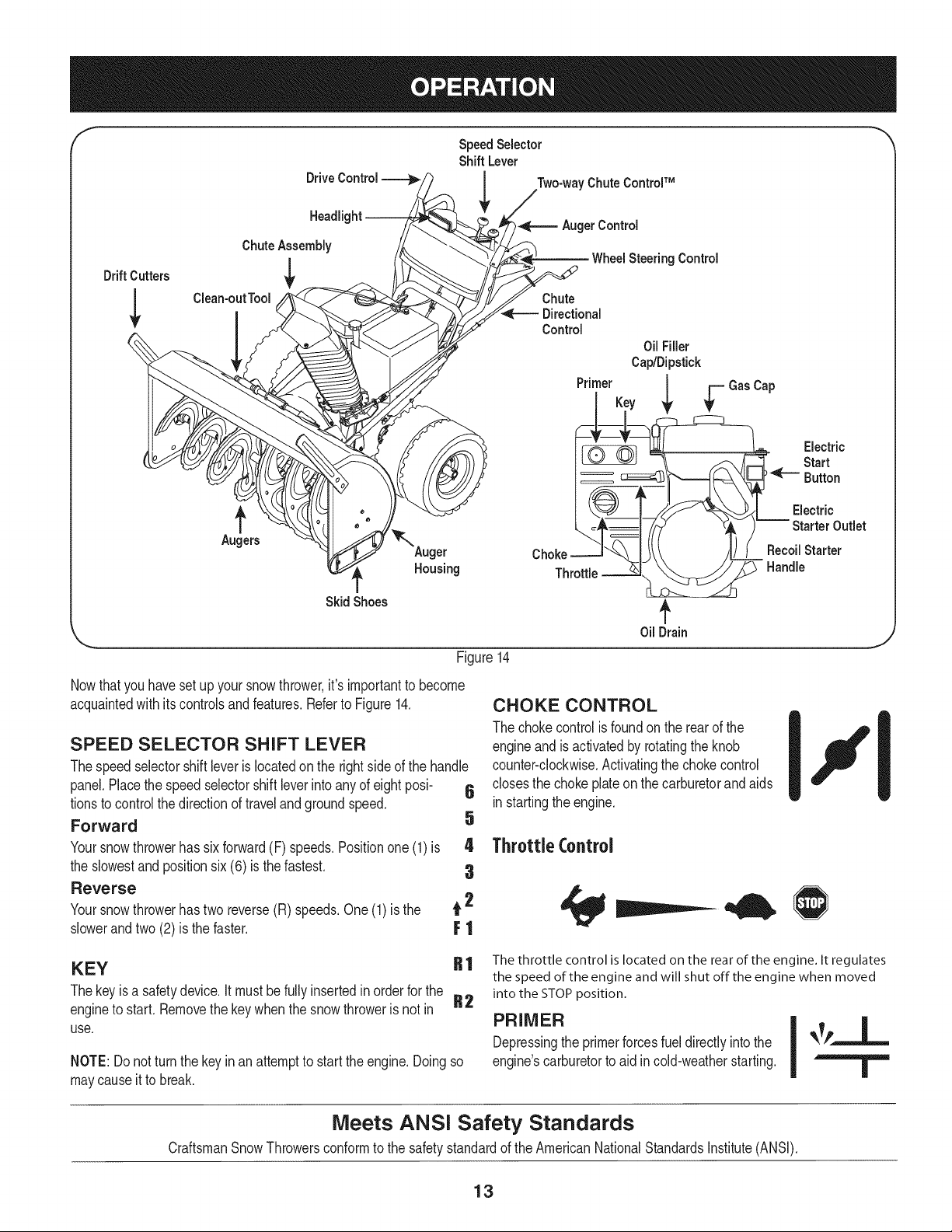
Nowthatyou havesetupyour snowthrower,it's importantto become
acquaintedwith its controlsandfeatures.Referto Figure14.
SPEED SELECTOR SHIFT LEVER
Thespeedselectorshiftleveris locatedon the rightsideof the handle
panel.Placethe speedselectorshift leverintoany of eightposi- 6
tionsto controlthedirectionof travelandgroundspeed.
Forward 5
Yoursnowthrowerhas sixforward(F) speeds.Positionone (1) is 4
the slowestand positionsix (6) is thefastest. 3
Reverse
Yoursnowthrowerhastwo reverse(R) speeds.One(1)is the t 2
slowerandtwo(2) is the faster. F ]
CHOKE CONTROL
The chokecontrolis foundon the rearof the
engineand is activatedby rotatingtheknob
counter-clockwise.Activatingthechokecontrol
closesthe chokeplateon thecarburetorand aids
instartingtheengine.
Throttle Control
KEY
Thekeyisa safetydevice.It mustbe fully insertedin orderfor the
engineto start.Removethe keywhenthe snow throweris not in
use.
NOTE:Do notturn the keyin an attemptto startthe engine.Doingso
maycauseit to break.
R 1 The throttle control is located on the rear of the engine. It regulates
the speed of the engine and will shut off the engine when moved
into the STOP position.
R2
PRIMER
Depressingthe primerforcesfueldirectlyintothe
engine'scarburetorto aid in cold-weatherstarting.
Meets ANSI Safety Standards
CraftsmanSnowThrowersconformto the safetystandardof the AmericanNationalStandardsInstitute(ANSI).
13
OIL FILL
Engineoillevelcan becheckedand oil addedthroughtheoil fill.
RECOIL STARTER HANDLE
Thishandleis usedto manuallystartthe engine.
ELECTRIC STARTER BUTTON
Pressingthe electricstarterbuttonengagestheengine'selectric
starterwhenpluggedintoa 120Vpowersource.
ELECTRIC STARTER OUTLET
Requiresthe useof a three-prongoutdoorextensioncord(included)
anda 120Vpowersource/walloutlet.
AUGERS
Whenengaged,the augersrotateanddrawsnowintothe auger
housing.
CHUTE ASSEMBLY
Snowdrawnintothe augerhousingis dischargedout the chute
assembly.
GAS CAP
Unthreadthe gascap to addgasolineto the fuel tank.
f
DRIVE
CONTROL
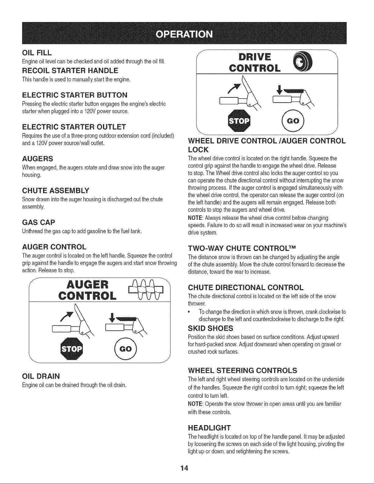
WHEEL DRIVE CONTROL/AUGER CONTROL
LOCK
The wheeldrivecontrolis locatedon the righthandle.Squeezethe
controlgrip againstthe handleto engagethe wheeldrive. Release
to stop.The Wheeldrive controlalso locksthe auger controlso you
can operatethe chutedirectionalcontrolwithoutinterruptingthe snow
throwingprocess.Ifthe augercontrolis engagedsimultaneouslywith
the wheeldrivecontrol,the operatorcan releasethe augercontrol (on
the left handle)and theaugerswill remainengaged.Releaseboth
controlsto stoptheaugersandwheeldrive.
NOTE:Alwaysreleasethewheeldrivecontrol beforechanging
speeds.Failureto do sowill resultinincreasedwearon yourmachine's
drive system.
AUGER CONTROL
Theaugercontrolis locatedonthe left handle.Squeezethecontrol
gripagainstthe handleto engagetheaugersandstart snowthrowing
action.Releaseto stop.
f
OIL DRAIN
Engineoilcan bedrainedthroughtheoil drain.
TWO-WAY CHUTE CONTROL TM
The distancesnow is throwncan be changedby adjustingthe angle
of the chuteassembly.Movethe chutecontrolforwardto decreasethe
distance,towardthe rearto increase.
CHUTE DIRECTIONAL CONTROL
The chutedirectionalcontrolis locatedonthe left sideof the snow
thrower.
• Tochangethedirectionin which snowis thrown,crankclockwiseto
dischargetothe leftandcounterclockwiseto dischargeto the right.
SKID SHOES
Positionthe skidshoesbasedon surfaceconditions.Adjustupward
for hard-packedsnow.Adjustdownwardwhenoperatingongravelor
crushedrocksurfaces.
WHEEL STEERING CONTROLS
The leftand rightwheelsteeringcontrolsare locatedon the underside
of the handles.Squeezethe rightcontrolto turn right;squeezethe left
controlto turn left.
NOTE:Operatethe snowthrowerin openareasuntilyouarefamiliar
withthesecontrols.
HEADLIGHT
The headlightis locatedon top of the handlepanel.It maybeadjusted
by looseningthe screwson eachside of the lighthousing,pivotingthe
light upor down,and retighteningthescrews.
14
DRIFT CUTTERS
Thedrift cuttersare designedfor use indeepsnow.Their useis
optionalfor normalsnowconditions.Maneuverthe snowthrowerso
thatthe cutterspenetratea high standingsnowdrift to assist snow
fallingintothe augersfor throwing.
CLEAN-OUT TOOL
Thechuteclean-outtool is convenientlyfastenedto the rearof the
augerhousingwith a mountingclip. Shouldsnow and ice become
lodgedin the chuteassemblyduring operation,proceedas followsto
safelycleanthe chute assemblyand chute opening:
Neveruseyour handsto clear a cloggedchuteassembly.Shut
off engineand remainbehindhandlesuntilall movingpartshave
stoppedbeforeunclogging.
1. ReleaseboththeAuger Controland theWheeldrivecontrol.
2. Stopthe engineby removingthe key.
3. Removetheclean-outtool fromthe clip whichsecuresit to the
rearof theaugerhousing.
4. Usethe shovel-shapedend of theclean-outtoolto dislodgeand
scoopanysnowandice whichhasformedin andnearthe chute
assembly.
5. Refastentheclean-outtoolto themountingclipon the rearofthe
augerhousing,reinsertthe keyandstartthesnowthrower'sengine.
6. Whilestandingin the operator'sposition(behindthe snow
thrower),engagethe augercontrol for a few secondsto clearany
remainingsnowand ice fromthe chute assembly.
BEFORE STARTING ENGINE
Read,understand,and followall instructionsandwarningson the
machineandin this manualbeforeoperating.
Oil
Theunit wasshippedwith oil inthe engine.Checkoil levelbeforeeach
operationto ensureadequateoil in the engine.For furtherinstructions,
referto the Service& Maintenancesectionof this manual.
1. Removethedipstickfromthe oilfill.
2. Checkand makesurethat the levelof oil is upto the FULLmark
onthe dipstick.
NOTE:Do NOTscrewthe screwtheoilcap into checkthe oillevel.
3. If theoil levelis not up to FULL,pourfreshmotoroil (5W-30,with
a minimumclassificationof SF/SG/SH/SJ)slowlythroughthe
opening.Replaceoil fill dipstickandcheckoil levelagain.
Gasoline
Useextremecarewhenhandlinggasoline.Gasolineis extremely
flammableand the vaporsare explosive.Never fuel the machine
indoorsor whilethe engineis hot or running.Extinguishcigarettes,
cigars, pipesand othersourcesof ignition.
Storegasolineina clean,approvedcontainerandkeepthecap in
placeonthe container.
• Makesurethat the containerfrom whichyou pourthe gasolineis
cleanandfree fromrustorotherforeignparticles.
• Alwaysfill the fuel tank outdoorsand use a funnelor spoutto
preventspilling.
• Fillfuel tank withclean, fresh,unleadedgasolinewitha minimum
of 87 octane.Freshfuel preventsgum fromformingin the fuel
systemor on essentialcarburetorparts.Purchasefuelin a
quantitythatcanbe usedwithin30 days.
• Neverfill the fuel tankcompletely.Fillthe tankto within1-1/2"
fromthe topto providespacefor expansiond fuel.
• Makesureto wipeoff any spilledfuel beforestartingthe engine.
STARTING THE ENGINE
1. Makecertainboththe augercontrol and wheeldrive controlarein
the disengaged(released)position.
2. Insertkeyinto slot. Makesureit snapsintoplace.Donot attempt
to turn the key.
NOTE:Theenginecannotstartwithoutthe keyfullyinsertedintothe
ignitionswitch.
Electric Starter
Theoptionalelectricstarteris equippedwitha groundedthree-wire
powercordandplug,and is designedto operateon 120voltAC
householdcurrent.It mustbe usedwith a properlygroundedthree-
prongreceptacleat all timesto avoidthe possibilityof electricshock.
Followall instructionscarefullyprior to operatingthe electricstarter.
Determinethatyour home'swiringis a three-wiregroundedsystem.
Aska licensedelectricianif youare notcertain.
Ifyou havea groundedthree-prongreceptacle,proceedas follows:
1. Plugthe extensioncord intothe outletlocatedonthe engine's
surface.Plugtheother endof extensioncord intoa three-prong
120-volt,grounded,ACoutletina well-ventilatedarea.
2. Rotatechokecontrolto FULL I,,"1chokeposition(fora cold
enginestart).
NOTE:If theengine is alreadywarm,placechokecontrolin the RUN
positioninsteadof CHOKEIJl position.
3. Pushprimerthree(3x) times,makingsureto cover vent hole
whenpushing.If engineis warm,pushprimeronlyonce.Always
coverventholewhenpushing.Coolweathermayrequirepriming
to berepeated.
4. Pushstarterbuttonto startengine.
Toprolongstarterlife,use shortstartingcycles(5 secondsmaximum
thenwaitone minute).
5. Oncethe enginestarts, immediatelyreleasestarterbutton.The
electricstarteris equippedwiththermaloverloadprotection;
systemwill temporarilyshut-downto allowstarterto cool if electric
starterbecomesoverloaded.
6. As the enginewarms,slowlyrotatethe chokecontrolto the RUN
position.If the enginefalters, restartengineand run with choke
at half-chokepositionfora shortperiodof time,andthenslowly
rotatethechokeinto the RUNposition.
15
7. Whendisconnectingtheextensioncord,alwaysunplugthe end
at the three-prongwalloutlet beforeunpluggingthe oppositeend
fromthe snowthrower.
Recoil Starter
1. Rotatechokecontrolto CHOKE IJl position.Ifengineis
alreadyhot, do not usethe CHOKE.
2. Pushprimerthreeto five(3-5)times,makingsure tocovervent
holewhenpushing.Ifengineiswarm,pushprimeronlyonce.
Alwayscovervent hole whenpushing.Cool weathermay require
primingto be repeated.
3. Graspthe recoilstarterhandleandslowlypullthe ropeout.At
the pointwhereit becomesslightlyharderto pull the rope,slowly
allowthe ropeto recoil.
4. Pull the starterhandlewitha firm, rapidstroke. Engineshould
start.Do not releasethe handleand allowit to snap back.Keepa
firmholdonthe starterhandleandallowit to slowlyrecoil.
5. As theengine warms,slowlyrotatethe chokecontrolto the RUN
position.If the enginefalters,restartengineandrunwithchoke
at half-chokepositionfor a shortperiodof time,andthen slowly
rotatethe chokeinto the RUNposition.
STOPPING THE ENGINE
Runenginefor a few minutesbeforestoppingto helpdry off any
moistureon the engine.
1. Movethrottlecontrolto STOPposition.
Do NOTmovethe chokecontrolto CHOKE 14¢1 positionto stop
theengine.Backfireor enginedamagemay occur.
2. Removethe key.Removingthe keywill reducethe possibilityof
unauthorizedstartingof the enginewhileequipmentis not in use.
Keepthe keyina safeplace.The enginecannotstart withoutthe
key.
3. Wipeall snowandmoisturefrom thearea aroundthe engineas
wellas the areainandaroundthe wheeldrivecontrolandauger
control.Also, engageand releasebothcontrolsseveraltimes.
TO ENGAGE WHEEL DRIVE
1. Movespeedselectorshift leverintooneof the sixforward(F)
positionsor two reverse(R) positions.Selecta speedappropriate
for the snowconditionsanda paceyou'recomfortablewith.
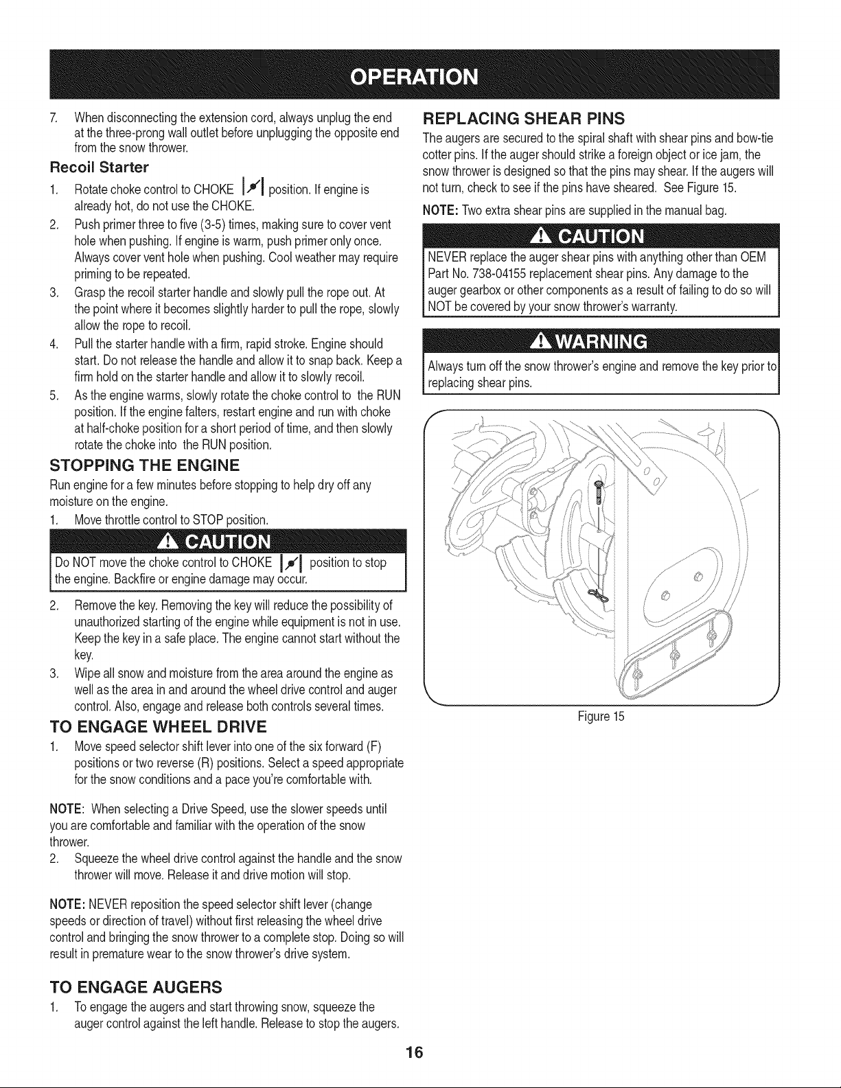
REPLACING SHEAR PINS
The augersare securedto the spiralshaftwith shearpinsand bow-tie
cotterpins.If the augershouldstrikea foreignobjector icejam, the
snowthrowerisdesignedso thatthe pinsmayshear.Ifthe augerswill
not turn,checkto see if the pinshavesheared. See Figure15.
NOTE: Twoextrashearpins are suppliedin the manualbag.
NEVERreplacethe augershearpins withanythingotherthan OEM
PartNo.738-04155replacementshearpins.Any damageto the
augergearboxor othercomponentsas a resultof failingto do sowill
NOTbecoveredbyyour snowthrower'swarranty.
Alwaysturn off the snowthrower'sengineand removethe key priorto
replacingshearpins.
Figure15
NOTE: Whenselectinga DriveSpeed,usethe slowerspeedsuntil
youarecomfortableandfamiliarwiththe operationof the snow
thrower.
2. Squeezethe wheeldrivecontrolagainstthe handleandthe snow
throwerwill move.Releaseit anddrive motionwill stop.
NOTE: NEVERrepositionthe speedselectorshift lever(change
speedsordirectionof travel)withoutfirst releasingthe wheeldrive
controlandbringingthe snowthrowerto a completestop.Doingso will
resultinprematurewearto the snowthrower'sdrive system.
TO ENGAGE AUGERS
1. Toengagetheaugersandstart throwingsnow,squeezethe
augercontrolagainstthe left handle.Releaseto stopthe augers.
16
MAINTENANCE SCHEDULE
Beforeperforminganytypeof maintenance/service,disengageall
controlsandstoptheengine.Waituntilallmovingpartshavecometo a
completestop.Removethekeyto preventunintendedstarting.Always
wearsafetyglassesduringoperationor whileperforminganyadjustments
orrepairs.
Followthe maintenanceschedulegivenbelow.This chart describes
serviceguidelinesonly. Usethe ServiceLog columnto keeptrackof
completedmaintenancetasks.To locate the nearest Sears Service
Centeror to scheduleservice,simplycontactSears at
1-800-4-MY-HOME®.
EachUse
1st5 - 8 hours
25 hours
50 hours
Annuallyor 100hours
BeforeStorage 1. Fuelsystem
Underheavyloador in high temperatures
1. Engineoil level
2. Looseor missinghardware
3. Unit and engine.
1. Engineoil
1. Engineoi11-
2. Controllinkagesand pivots
1. Engineoil
1. Sparkplug
= =
1. Check
2. Tightenor replace
3. Clean
1. Change
1. Change
2. Lubewithlightoil
1. Change
1. Cleanand re-gap,orelse replace
withnew plug.
1. Runengineuntilit stopsfrom lackof
fuel oradda gasolineadditiveto the
gas in thetank.
ENGINE MAINTENANCE
Checking Engine Oil
Beforelubricating,repairing,or inspecting,disengageall controlsand
stopengine.Waituntilall movingpartshavecometo a completestop.
Removethekey to preventunintendedfiringofthe engine.
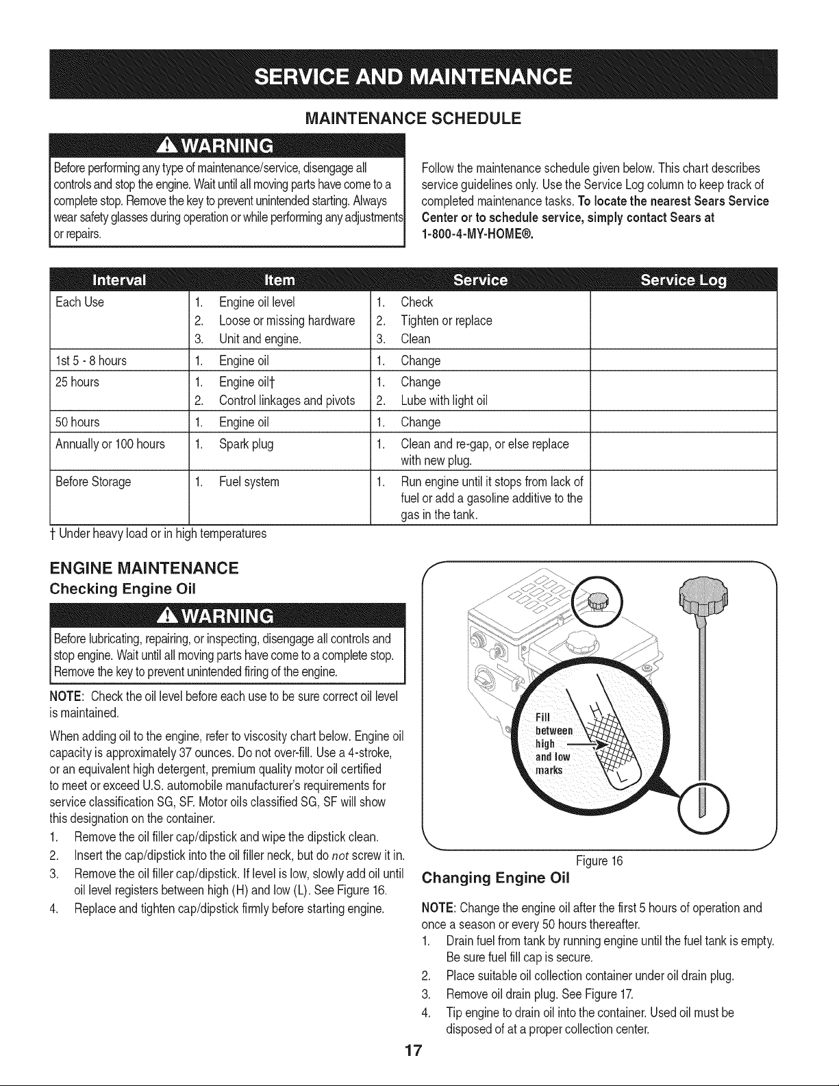
NOTE: Checktheoil levelbeforeeachuseto besurecorrectoil level
is maintained.
Whenaddingoilto the engine,referto viscositychart below.Engineoil
capacityis approximately37 ounces.Donot over-fill.Usea 4-stroke,
oran equivalenthighdetergent,premiumqualitymotoroilcertified
to meetorexceedU.S.automobilemanufacturer'srequirementsfor
serviceclassificationSG, SR MotoroilsclassifiedSG, SFwill show
thisdesignationonthe container.
1. Removethe oil fillercap/dipstickand wipethe dipstickclean.
2. Insertthe cap/dipstickintothe oil filler neck,butdo not screwit in.
3. Removethe oil fillercap/dipstick.If levelis low, slowlyadd oil until
oil levelregistersbetweenhigh(H) andlow (L). SeeFigure16.
4. Replaceand tighten cap/dipstickfirmlybeforestartingengine.
Figure16
Changing Engine Oil
J
NOTE:Changethe engineoil afterthefirst 5 hoursof operationand
once a seasonor every50 hoursthereafter.
1. Drainfuel fromtankby runningengineuntilthefuel tankis empty.
Besurefuel fill capis secure.
2. Placesuitableoil collectioncontainerunderoil drainplug.
3. Removeoil drainplug.SeeFigure17.
4. Tip engineto drain oil intothe container.Usedoil mustbe
disposedof at a propercollectioncenter.
17
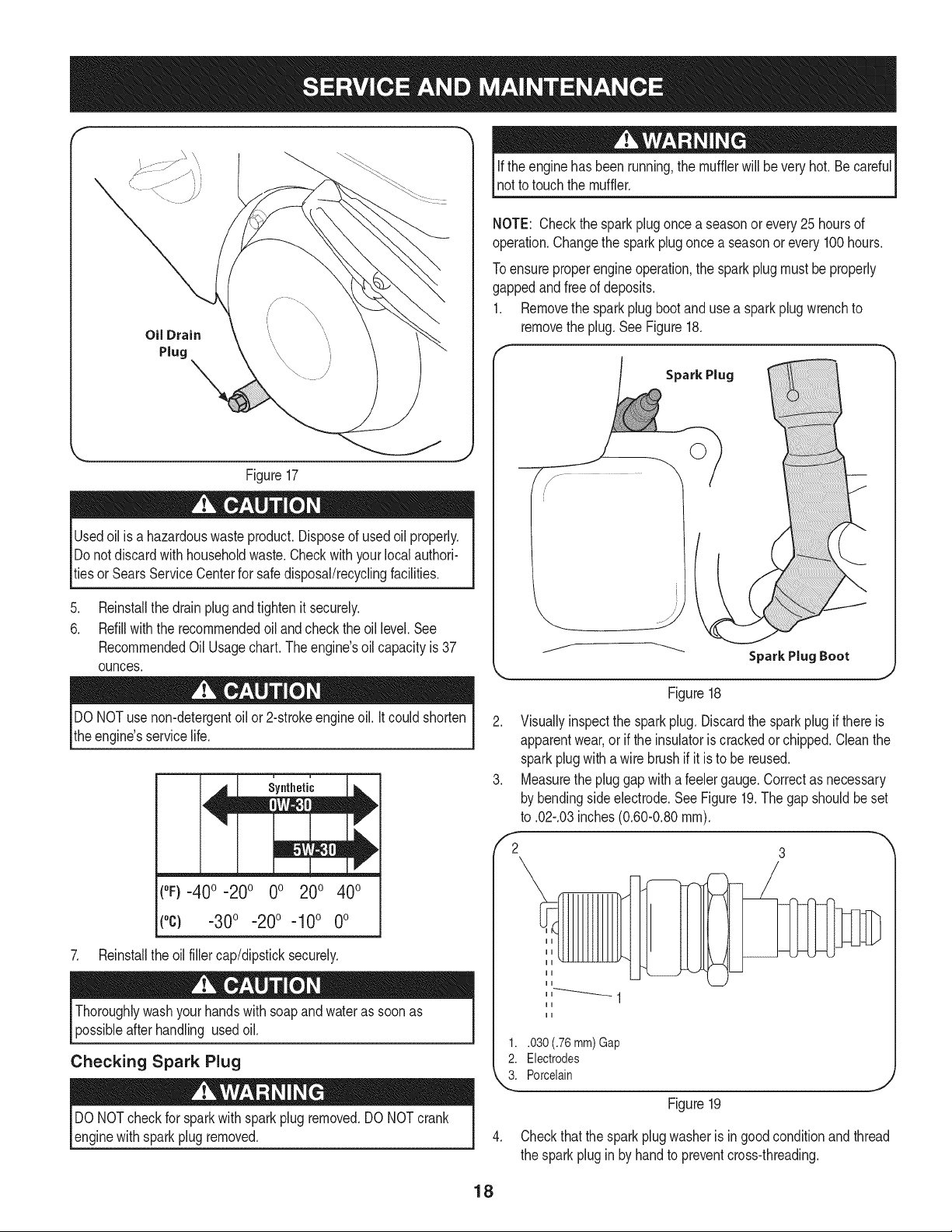
f
Oil Drain
Plug
Figure17
Usedoil is a hazardouswasteproduct.Disposeof usedoil properly.
Donotdiscardwith householdwaste.Checkwithyourlocalauthori-
tiesor SearsServiceCenterfor safedisposal/recyclingfacilities.
.
6.
Reinstallthe drain plugand tightenit securely.
Refillwiththe recommendedoil and checkthe oil level.See
RecommendedOil Usage chart. The engine's oil capacity is 37
ounces.
Ifthe enginehas beenrunning,the mufflerwill be very hot. Be careful
not to touchthe muffler.
NOTE: Checkthe spark plugonce a seasonor every25 hoursof
operation.Changethe sparkplug oncea seasonorevery100hours.
Toensureproperengineoperation,the sparkplugmustbeproperly
gappedandfree of deposits.
1. Removethe sparkplugbootand usea sparkplugwrenchto
removethe plug.SeeFigure18.
Spark Plug
DONOTuse non-detergentoilor 2-strokeengineoil. Itcould shorten
the engine'sservicelife.
(°F}=40o =20o 0o 200 400
(°c) -30° -20° -10 ° 0°
7. Reinstallthe oilfillercap/dipsticksecurely.
Thoroughlywashyour handswith soapand water as soonas
possibleafterhandling usedoil.
Checking Spark Plug
DO NOTcheckfor sparkwithsparkplugremoved.DO NOTcrank
enginewithsparkplugremoved.
Figure18
2. Visuallyinspectthe sparkplug. Discardthe sparkplugif there is
apparentwear,or if the insulatoris crackedor chipped.Cleanthe
sparkplugwithawire brushif it is to be reused.
3. Measurethe pluggapwitha feelergauge.Correctas necessary
bybendingsideelectrode.See Figure19.Thegap shouldbe set
to .02-.03inches(0.60-0.80ram).
,'2 3
1..030 (.76 mm) Gap
2. Electrodes
k"_i Porcelain
Figure19
4. Checkthat the spark plugwasheris ingoodconditionandthread
the sparkpluginby handto preventcross-threading.
18
5. Afterthe sparkplug is seated,tightenwitha spark plugwrenchto
compressthe washer.
NOTE:Wheninstallinga newsparkplug,tighten1/2-turnafterthe
sparkplugseatsto compressthe washer.Whenreinstallinga used
sparkplug,tighten 1/8-to 1/4-turnafter the sparkplug seatsto
compressthe washer.
hot andcan ine.
CARBURETOR ADJUSTMENT
Thecarburetoris notuseradjustable.ContactSearsParts& Repairfor
adjustment.
LUBRICATION
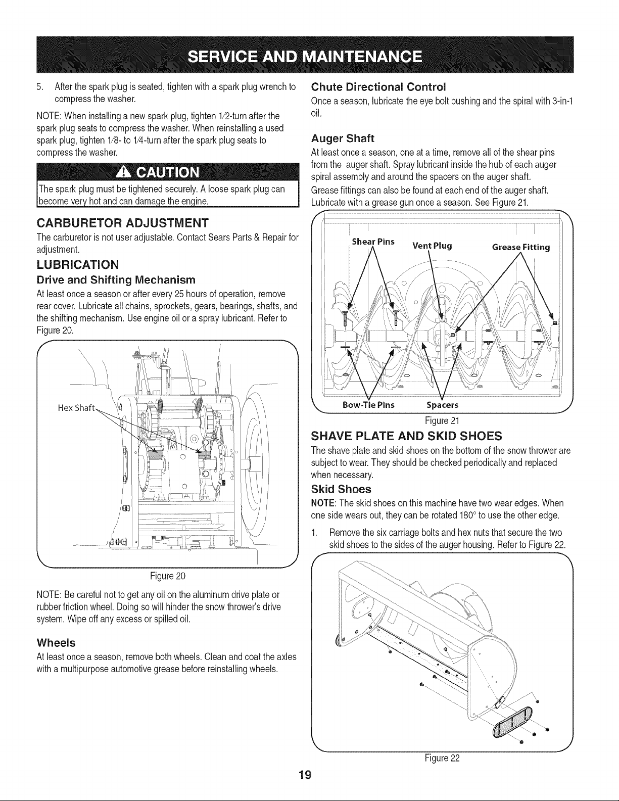
Drive and Shifting Mechanism
At leastoncea seasonor afterevery25 hoursof operation,remove
rearcover.Lubricateall chains,sprockets,gears,bearings,shafts,and
the shiftingmechanism.Useengineoil or a spraylubricant.Referto
Figure20.
f
f ...............
Figure20
NOTE:Becarefulnotto get any oilon thealuminumdrive plateor
rubberfrictionwheel.Doingso will hinderthe snowthrower'sdrive
system.Wipeoff anyexcessor spilledoil.
Wheels
At leastoncea season,removebothwheels.Cleanand coat theaxles
witha multipurposeautomotivegreasebeforereinstallingwheels.
Chute Directional Control
Once aseason,lubricatethe eyebolt bushingand the spiralwith 3-in-1
oil.
Auger Shaft
At leastoncea season,oneat a time, removeall of theshearpins
fromthe augershaft.Spraylubricantinsidethe hub of eachauger
spiralassemblyandaroundthe spacerson the augershaft.
Greasefittings can alsobe foundat each end of the augershaft.
Lubricatewitha greasegun oncea season.See Figure21.
Bow=Tie Pins S pacers
Figure21
SHAVE PLATE AND SKID SHOES
The shaveplateandskidshoeson the bottomof the snowthrowerare
subjectto wear.Theyshouldbe checkedperiodicallyand replaced
when necessary.
Skid Shoes
NOTE:The skidshoesonthis machinehavetwo wearedges.When
one sidewearsout, they can be rotated 1800to use theotheredge.
1. Removethe sixcarriageboltsandhex nutsthatsecurethetwo
skidshoesto the sidesof the augerhousing.Referto Figure22.
19
Figure22
J
2. Positionthe new skid shoesand securewith the carriagebolts
andhex nuts.Makecertainthe skidshoesare adjustedto be
level.
Shave Plate
1. Removethehex nutsandcarriagebolts that securethe shave
plateto the bottomof the housing.
2. Removethe rearmost hexnutand carriagebolt securingthe back
of eachskidshoeto the sidesof the housing.Loosenthefour
remaininghexnuts securingthe skid shoes.
3. Slide theshaveplateout of the off-set slotat thebottomof the
housing,andfrombetweenthe skidshoesandside panelsof the
housing.
4. With the mountingholestowardthe back of the unit, slidethe new
shaveplateinto positionandsecurewiththe fastenersremoved
previously.
ADJUSTMENTS
Speed selector Rod
If thefull rangeof speeds(forwardand reverse)cannotbe achieved,
referto Figure20 to the leftandadjustthe speedselector rod as
follows:
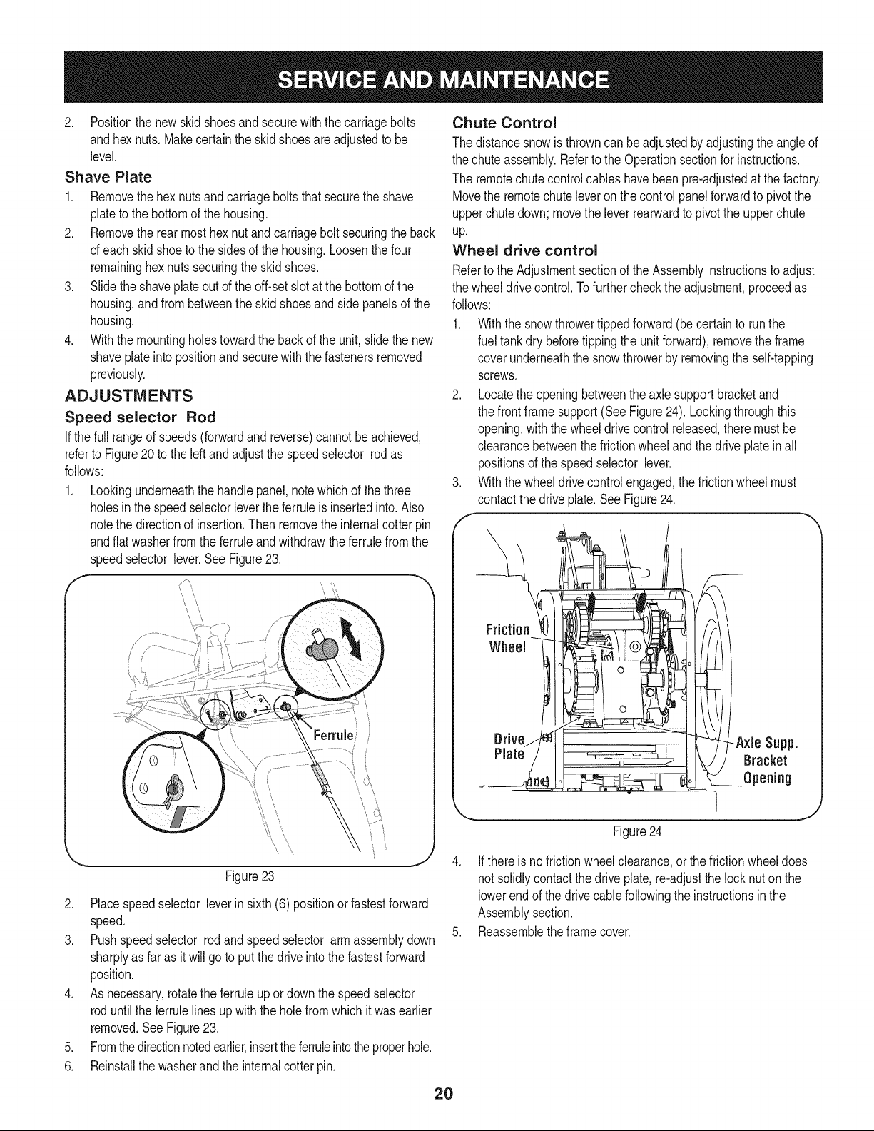
1. Lookingunderneaththe handlepanel,notewhich of thethree
holesin the speedselectorleverthe ferruleis insertedinto. Also
notethe directionof insertion.Thenremovethe internalcotter pin
andflatwasherfromthe ferruleandwithdrawthe ferrulefromthe
speedselector lever.SeeFigure23.
\ \
\
Ferrule
\ \
Figure23
2. Placespeedselector leverin sixth(6) positionor fastestforward
speed.
3. Pushspeedselector rodand speedselector armassemblydown
sharplyas faras itwill goto putthe driveintothe fastestforward
position.
4. As necessary,rotatethe ferruleupordownthe speedselector
roduntilthe ferrulelinesup with the holefrom which itwas earlier
removed.See Figure23.
5. Fromthedirectionnotedearlier,inserttheferruleintothe properhole.
6. Reinstallthe washerandthe internalcotter pin.
Chute Control
The distancesnow is throwncanbe adjustedbyadjustingthe angleof
the chuteassembly.Referto the Operationsectionfor instructions.
The remotechutecontrolcableshavebeen pre-adjustedat the factory.
Movethe remotechuteleveron the controlpanelforwardto pivotthe
upperchutedown;movethe leverrearwardto pivotthe upperchute
up.
Wheel drive control
Referto theAdjustmentsectionof theAssemblyinstructionsto adjust
the wheeldrivecontrol.Tofurther checkthe adjustment,proceedas
follows:
1. With the snowthrowertippedforward(becertainto runthe
fuel tankdry beforetippingthe unitforward),removethe frame
coverunderneaththe snowthrowerby removingthe self-tapping
screws.
2. Locatethe openingbetweenthe axle supportbracketand
the frontframesupport(See Figure24). Lookingthroughthis
opening,with the wheeldrivecontrol released,there mustbe
clearancebetweenthe frictionwheelandthe drive plateinall
positionsof the speedselector lever.
3. With the wheeldrivecontrolengaged,the frictionwheel must
contactthe driveplate.SeeFigure24.
Friction
Wheel
Figure24
4. Ifthereis nofrictionwheelclearance,or thefrictionwheeldoes
notsolidlycontactthe drive plate,re-adjustthe locknut onthe
lowerend of the drivecablefollowingthe instructionsinthe
Assemblysection.
5. Reassembletheframecover.
2O
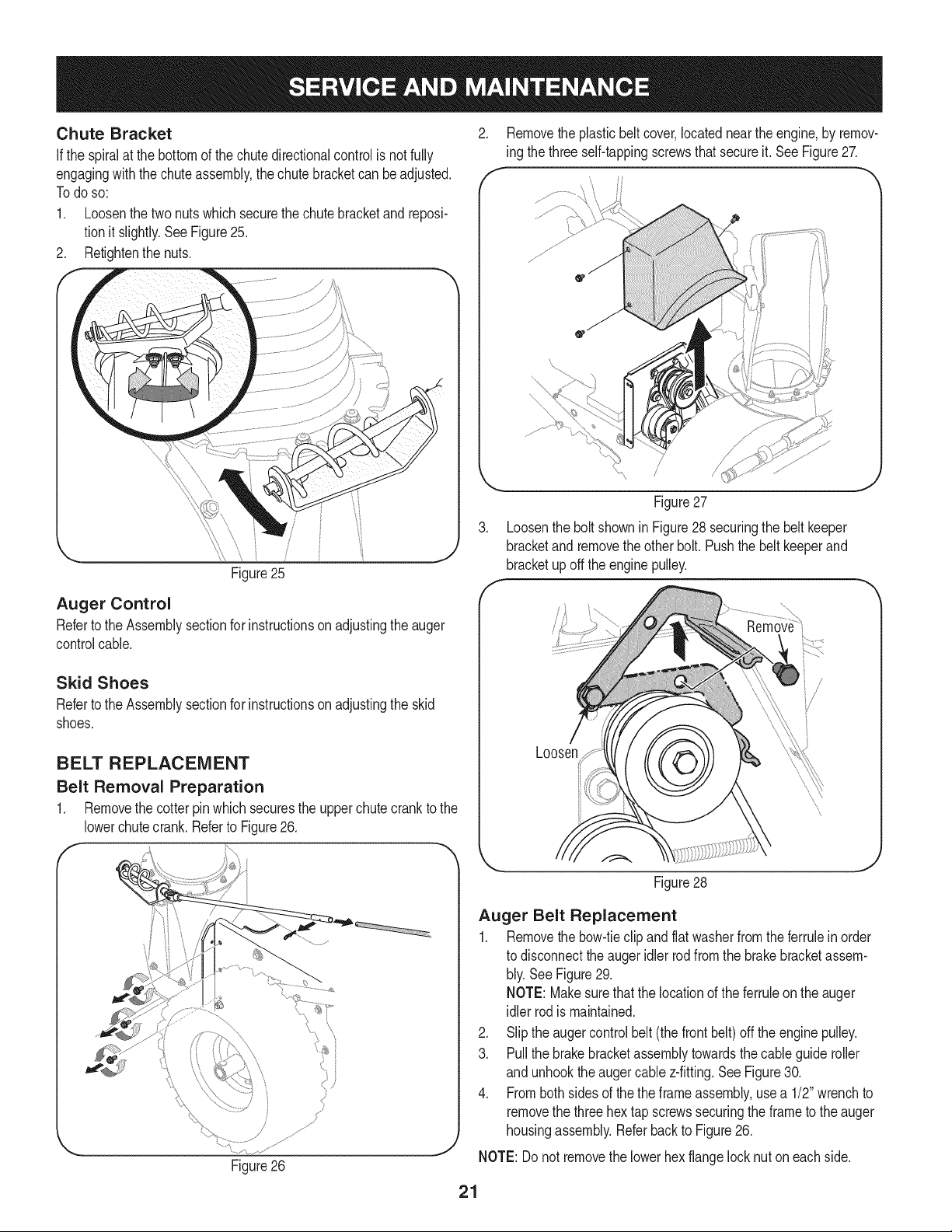
Chute Bracket
Ifthe spiralat the bottomof the chutedirectionalcontrolis not fully
engagingwiththe chuteassembly,the chute bracketcan beadjusted.
Todo so:
1. Loosenthe twonutswhichsecurethe chutebracketand reposi-
tion it slightly.SeeFigure25.
2. Retightenthenuts.
/
Figure25
Auger Control
Referto the Assemblysectionfor instructionson adjustingtheauger
controlcable.
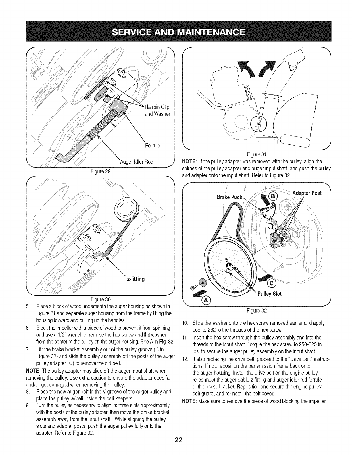
2. Removethe plasticbeltcover,locatednearthe engine,by remov-
ing thethree self-tappingscrewsthatsecureit.See Figure27.
\
Figure27
3. Loosenthe boltshownin Figure28 securingthe beltkeeper
bracketand removethe otherbolt.Pushthe belt keeperand
bracketupoff theengine pulley.
Skid Shoes
Referto the Assemblysectionfor instructionsonadjustingthe skid
shoes.
BELT REPLACEMENT
Belt Removal Preparation
1. Removethe cotter pinwhichsecuresthe upperchute crank tothe
lowerchutecrank.Referto Figure26.
Figure26
Figure28
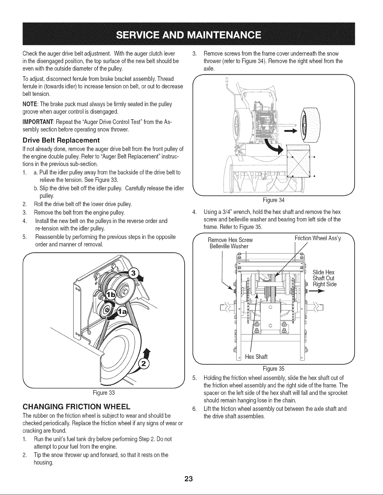
Auger Belt Replacement
1. Removethe bow-tieclipand flat washerfromthe ferruleinorder
to disconnecttheaugeridlerrodfromthe brakebracketassem-
bly.SeeFigure29.
NOTE: Makesurethatthe locationof the ferruleonthe auger
idlerrodis maintained.
2. Slip the augercontrol belt(the front belt)off the enginepulley.
3. Pullthe brakebracketassemblytowardsthe cableguideroller
and unhooktheaugercablez-fitting.SeeFigure30.
4. Frombothsidesof thethe frameassembly,usea 1/2"wrenchto
removethe threehextap screwssecuringthe frameto theauger
housingassembly.Referbackto Figure26.
NOTE: Donot removethe lowerhexflangelocknut oneach side.
21
\
Figure29
AugerIdler Rod
Figure30
5. Placea blockof woodunderneaththeaugerhousingas shownin
Figure31and separateaugerhousingfromtheframeby tiltingthe
housingforwardand pullingup the handles.
6. Blocktheimpellerwitha pieceof woodto preventit fromspinning
andusea 1/2"wrenchto removethehexscrewand flat washer
fromthecenterof thepulleyon the augerhousing.SeeA in Fig.32.
7. Lift the brakebracketassemblyout of the pulleygroove(B in
Figure32) andslidethe pulleyassemblyoffthe postsof theauger
pulleyadapter(C) to removetheold belt.
NOTE:Thepulleyadaptermay slideoff theaugerinputshaftwhen
removingthe pulley.Useextracautionto ensurethe adapterdoes fall
and/orget damagedwhenremovingthe pulley.
8. Placethe newaugerbelt in the V-grooveof theaugerpulleyand
placethe pulleyw/belt insidethe belt keepers.
9. Turnthepulleyas necessaryto alignits threeslotsapproximately
withthe postsof the pulleyadapter,thenmovethe brakebracket
assemblyawayfromthe inputshaft. Whilealigningthe pulley
slotsandadapterposts, pushthe augerpulleyfully ontothe
adapter.Referto Figure32.
Figure31
NOTE: Ifthe pulleyadapterwas removedwith the pulley,align the
splinesof thepulleyadapterand auger inputshaft,andpushthe pulley
andadapteronto the inputshaft. Referto Figure32.
/
/ pterPost
Brake
Pulley Slot
Figure32
10. Slidethe washeronto the hexscrewremovedearlierandapply
Loctite262 to the threadsof the hexscrew.
11. Insertthe hexscrewthroughthe pulleyassemblyand intothe
threadsof the input shaft.Torquethe hexscrewto 250-325in.
Ibs.to securethe auger pulleyassemblyonthe inputshaft.
12. Ifalso replacingthedrive belt,proceedto the"DriveBelt" instruc-
tions. Ifnot, repositionthetransmissionframebackonto
the augerhousing.Installthe drivebelton the enginepulley,
re-connectthe augercablez-fittingand auger idler rod ferrule
to the brakebracket.Repositionand securethe enginepulley
beltguard,andre-installthebelt cover.
NOTE:Makesureto removethe pieceof wood blockingthe impeller.
22
Checkthe auger drivebeltadjustment. Withthe auger clutchlever
inthe disengagedposition,thetop surfaceof the newbelt shouldbe
evenwiththeoutsidediameterof the pulley.
Toadjust,disconnectferrulefrombrakebracketassembly.Thread
ferrulein(towardsidler) to increasetensionon belt,orout to decrease
belttension.
NOTE:Thebrakepuckmustalwaysbe firmly seatedin the pulley
groovewhenaugercontrol is disengaged.
IMPORTANT:Repeatthe "AugerDriveControlTest"fromthe As-
semblysectionbeforeoperatingsnow thrower.
Drive Belt Replacement
If notalreadydone,removethe augerdrivebelt from thefront pulleyof
theenginedoublepulley.Referto "AugerBeltReplacement"instruc-
tionsinthe previoussub-section.
1. a. Pull the idlerpulleyawayfromthe backsideof the drivebeltto
relievethetension.See Figure33.
b. Slipthe drivebelt offthe idlerpulley. Carefullyreleasethe idler
pulley.
2. Roll thedrive beltoff the lowerdrive pulley.
3. Removethe beltfromthe enginepulley.
4. Installthe newbelt on the pulleysinthe reverseorderand
re-tensionwiththe idlerpulley.
5. Reassembleby performingthe previousstepsinthe opposite
orderandmannerof removal.
f
J
Figure33
CHANGING FRICTION WHEEL
The rubberon the frictionwheelis subjectto wearand shouldbe
checkedperiodically.Replacethe frictionwheelif any signsof wearor
crackingare found.
1. Runthe unit'sfuel tankdry beforeperformingStep2. Do not
attemptto pourfuel fromthe engine.
2. Tipthe snowthrowerup and forward,so thatit restsonthe
housing.
3. Removescrewsfrom theframecoverunderneaththe snow
thrower(referto Figure34). Removethe rightwheelfrom the
axle.
f
e
.
f
Figure34
Usinga3/4" wrench,holdthe hexshaftand removethe hex
screwandbellevillewasherand bearingfrom left sideof the
frame.Referto Figure35.
RemoveHexScrew
BellevilleWasher
FrictionWheelAss'y.
HexShaft
SlideHex
ShaftOut
RightSide
.._
J
Figure35
5. Holdingthefrictionwheelassembly,slidethe hexshaftout of
the frictionwheelassemblyandthe rightside of the frame.The
spaceron the left sideof the hexshaftwill fall and the sprocket
shouldremainhanginglose inthe chain.
6. Liftthe frictionwheelassemblyout betweenthe axleshaft and
the driveshaftassemblies.
23
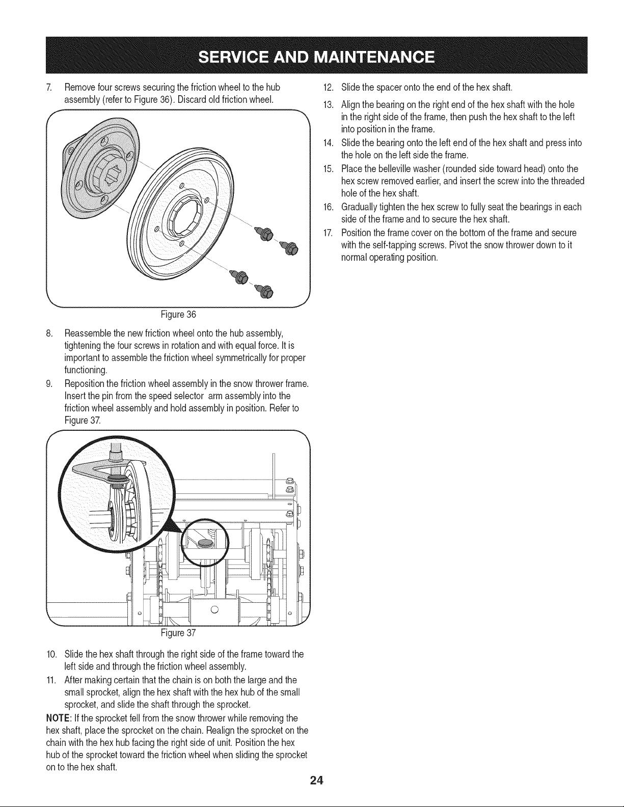
7. Removefourscrewssecuringthe frictionwheelto the hub 12.
assembly(referto Figure36). Discardoldfrictionwheel.
13.
Slidethe spacerontothe endof the hex shaft.
Alignthe bearingonthe rightendof thehex shaftwiththe hole
inthe rightside of the frame,then pushthe hexshaftto the left
intopositioninthe frame.
14. Slidethe bearingontothe leftendof the hex shaftandpressinto
the holeon theleft sidethe frame.
15. Placethe bellevillewasher(roundedside towardhead)ontothe
hexscrewremovedearlier,and insert thescrewinto thethreaded
holeof the hex shaft.
16. Graduallytightenthe hexscrewto fullyseatthe bearingsineach
sideof the frameandto securethe hex shaft.
17. Positionthe framecoveron the bottomof the frameand secure
withthe self-tappingscrews.Pivotthe snowthrowerdownto it
normaloperatingposition.
Figure36
8. Reassemblethe newfrictionwheelontothe hub assembly,
tighteningthe fourscrewsin rotationand with equal force.It is
importantto assemblethefrictionwheelsymmetricallyfor proper
functioning.
9. Repositionthe frictionwheelassemblyin the snowthrowerframe.
Insertthe pinfromthe speedselector armassemblyintothe
frictionwheelassemblyandholdassemblyin position.Referto
Figure37.
10. Slide thehex shaftthroughthe rightsideof the frametowardthe
left sideand throughthe frictionwheelassembly.
11. After makingcertain that the chainis on boththe largeandthe
smallsprocket,align the hexshaftwith the hexhub of the small
sprocket,and slidethe shaftthroughthe sprocket.
NOTE:Ifthe sprocketfellfromthe snowthrowerwhile removingthe
hexshaft,placethe sprocketon thechain. Realignthe sprocketon the
chainwiththe hexhubfacingthe rightsideof unit.Positionthe hex
hubof the sprockettowardthe frictionwheelwhen slidingthe sprocket
onto the hex shaft.
24
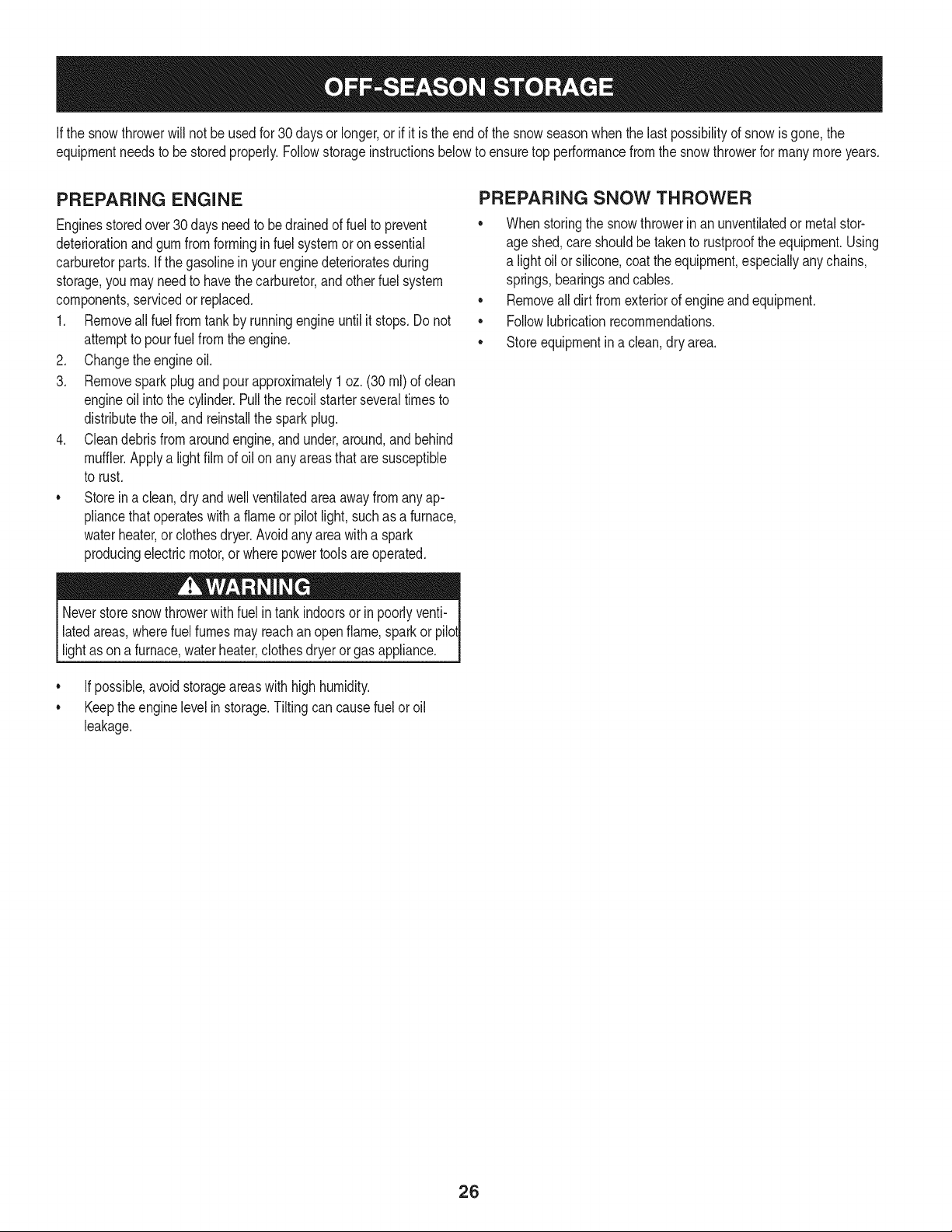
Ifthe snowthrowerwillnot be usedfor30 daysor longer,or if it is the end of the snowseasonwhenthe last possibilityof snowis gone,the
equipmentneedsto bestoredproperly.Followstorageinstructionsbelowto ensuretop performancefromthe snowthrowerfor manymoreyears.
PREPARING ENGINE
Enginesstoredover30 days need to be drainedof fuel to prevent
deteriorationandgumfromforminginfuel systemor onessential
carburetorparts.If thegasolinein yourenginedeterioratesduring
storage,youmay needto havethe carburetor,and otherfuel system
components,servicedor replaced.
1. Removeall fuel fromtank by runningengineuntil it stops.Donot
attemptto pourfuel fromthe engine.
2. Changethe engineoil.
3. Removesparkplugandpourapproximately1oz.(30 rnl) of clean
engineoil intothe cylinder.Pullthe recoilstarterseveraltimesto
distributetheoil, and reinstallthe sparkplug.
4. Cleandebrisfromaroundengine,andunder,around,andbehind
muffler.Applya lightfilmof oilon anyareasthatare susceptible
to rust.
• Storeina clean,dry and wellventilatedareaawayfromanyap-
pliancethat operateswith a flame or pilotlight,suchas a furnace,
waterheater,or clothesdryer.Avoidany areawitha spark
producingelectricmotor,or wherepowertoolsareoperated.
Neverstoresnowthrowerwithfuel intank indoorsor in poorlyventi-
latedareas,wherefuel fumesmay reachan openflame,spark or pilol
lightas ona furnace,waterheater,clothesdryer or gas appliance.
• If possible,avoidstorageareaswithhighhumidity.
• Keepthe enginelevelin storage.Tiltingcan causefuel oroil
leakage.
PREPARING SNOW THROWER
Whenstoringthe snowthrowerin an unventilatedormetalstor-
age shed,careshouldbe taken to rustprooftheequipment.Using
a light oil or silicone,coat theequipment,especiallyanychains,
springs,bearingsand cables.
• Removealldirt fromexteriorof engineandequipment.
• Followlubricationrecommendations.
• Storeequipmentin a clean,dry area.
26
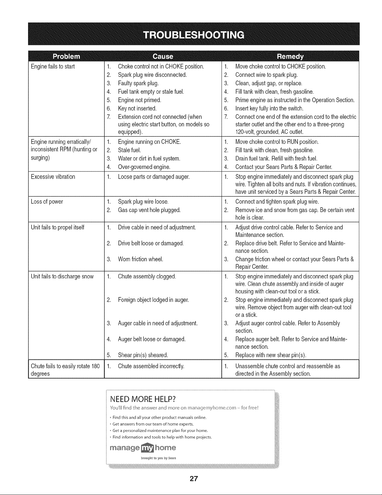
Enginefailsto start
Enginerunningerratically/
inconsistentRPM(huntingor
surging)
Excessivevibration
Lossof power
Unitfailsto propelitself
Unitfailsto dischargesnow
1. Chokecontrolnot in CHOKEposition.
2. Sparkplug wiredisconnected.
3. Faultysparkplug.
4. Fueltank emptyor stalefuel.
5. Enginenot primed.
6. Keynot inserted.
7. Extensioncordnot connected(when
usingelectricstartbutton,on modelsso
equipped).
1. Enginerunningon CHOKE.
2. Stalefuel.
3. Wateror dirt in fuel system.
4. Over-governedengine.
1. Loosepartsor damagedauger.
1. Sparkplug wireloose.
2. Gascap vent hole plugged.
1. Drivecable inneedof adjustment.
2. Drivebelt looseor damaged.
3. Wornfrictionwheel.
1. Chuteassemblyclogged.
2. Foreignobjectlodgedin auger.
3. Augercablein needof adjustment.
4. Augerbelt looseor damaged.
5. Shearpin(s) sheared.
1. Chuteassembledincorrectly.
1. Movechokecontrolto CHOKEposition.
2. Connectwireto sparkplug.
3. Clean,adjustgap,or replace.
4. Fill tank with clean,freshgasoline.
5. Primeengineas instructedin the OperationSection.
6. Insertkey fully intothe switch.
7. Connectoneendof the extensioncordto the electric
starteroutletandthe otherendto a three-prong
120-volt,grounded,ACoutlet.
1. Movechokecontrolto RUNposition.
2. Fill tank with clean,freshgasoline.
3. Drainfueltank. Refillwith fresh fuel.
4. ContactyourSearsParts & RepairCenter.
1. Stopengineimmediatelyand disconnectsparkplug
wire.Tightenall boltsand nuts.Ifvibrationcontinues,
haveunit servicedbya SearsParts& RepairCenter.
1. Connectandtightensparkplugwire.
2. Removeiceand snowfrom gascap. Becertainvent
holeis clear.
1. Adjustdrivecontrolcable. Referto Serviceand
Maintenancesection.
2. Replacedrive belt. Referto Serviceand Mainte-
nancesection.
3. Changefrictionwheelorcontactyour SearsParts&
RepairCenter.
1. Stopengineimmediatelyand disconnectsparkplug
wire.Cleanchuteassemblyandinsideof auger
housingwith clean-outtoolor a stick.
2. Stopengineimmediatelyand disconnectsparkplug
wire.Removeobject fromauger with clean-outtool
ora stick.
3. Adjustaugercontrolcable. Referto Assembly
section.
4. Replaceauger belt. Referto Serviceand Mainte-
nancesection.
5. Replacewith newshearpin(s).
Chutefailsto easilyrotate180 1. Unassemblechutecontrolandreassembleas
degrees directedinthe Assemblysection.
27

27
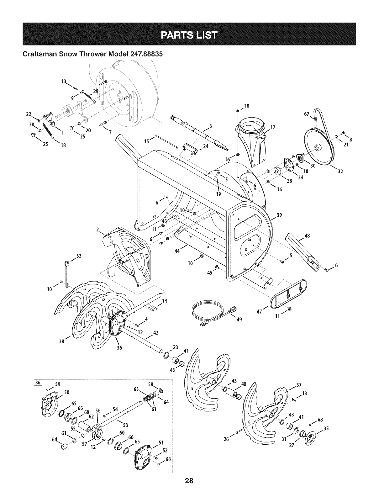
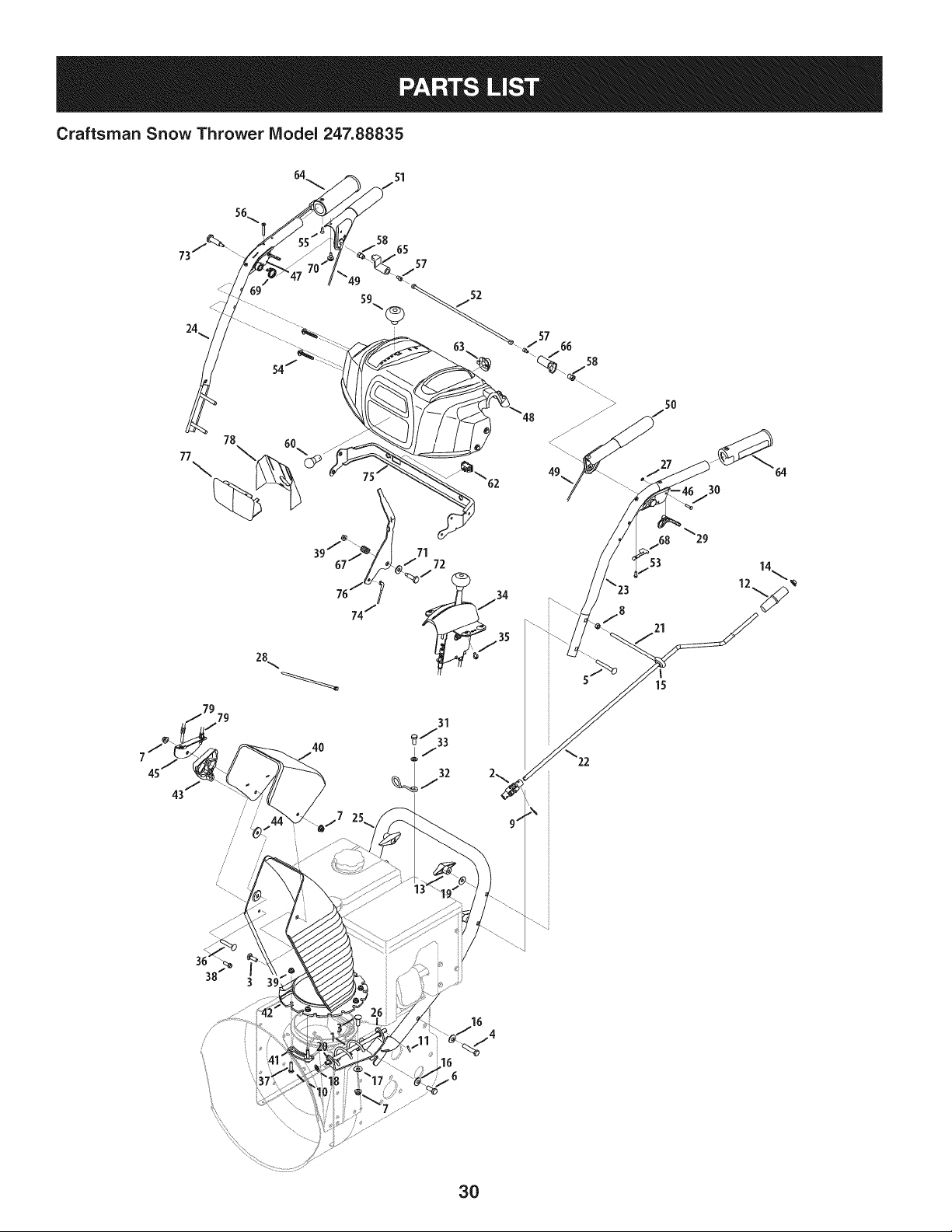
Craftsman Snow Thrower Model 247.88835
19
47
48
43
28
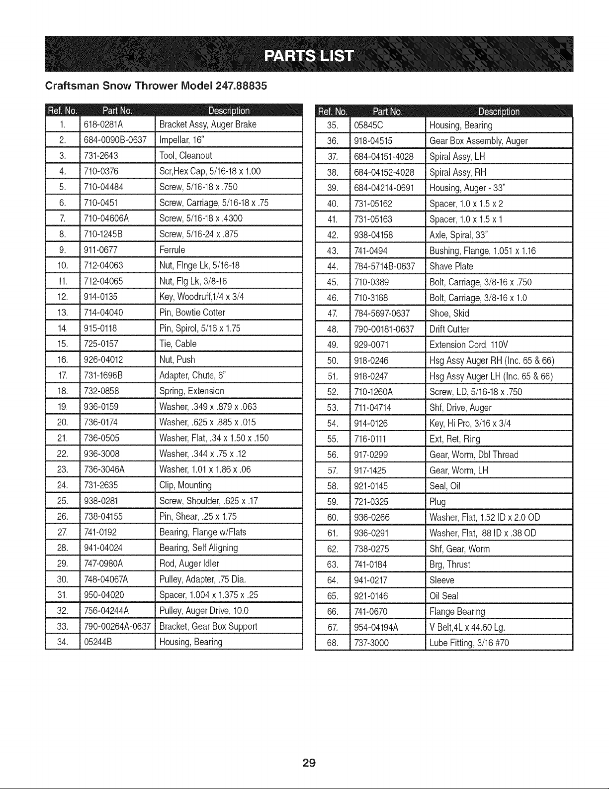
Craftsman Snow Thrower IViodel 247.88835
D = " _ 0
618-0281A BracketAssy,AugerBrake
2. 684-0090B-0637 Impellar,16"
3. 731-2643 Tool,Cleanout
4. 710-0376 Scr,HexCap,5/16-18x 1.00
5. 710-04484 Screw,5/16-18x .750
6. 710-0451 Screw,Carriage,5/16-18x .75
7. 710-04606A Screw,5/16-18x .4300
8. 710-1245B Screw,5/16-24x .875
9. 911-0677 Ferrule
10. 712-04063 Nut, FlngeLk,5/16-18
11. 712-04065 Nut, FigLk, 3/8-16
12. 914-0135 Key,Woodruff,I/4x 3/4
13. 714-04040 Pin, BowtieCotter
14. 915-0118 Pin,Spirol,5/16x 1.75
15. J 725-0157 J Tie,Cable
16. 926-04012 Nut, Push
17. 731-1696B Adapter,Chute,6"
18. 732-0858 Spring,Extension
19. 936-0159 Washer,.349x .879x .063
20. 736-0174 Washer,.625x .885x .015
21. 736-0505 Washer,Flat, .34x 1.50x .150
22. 936-3008 Washer,.344 x .75x .12
23. 736-3046A Washer,1.01x 1.86x .06
24. 731-2635 Clip,Mounting
25. 938-0281 Screw,Shoulder,.625x .17
26. 738-04155 Pin,Shear,.25x 1.75
27. 741-0192 Bearing,Flangew/Flats
28. 941-04024 Bearing,SelfAligning
29. 747-0980A Rod,AugerIdler
30. 748-04067A Pulley,Adapter,.75Dia.
31. 950-04020 Spacer,1.004x 1.375x .25
32. 756-04244A Pulley,AugerDrive,10.0
33. 790-00264A-0637 Bracket,GearBoxSupport
34. 05244B Housing,Bearing
D = O
05845C Housing,Bearing
36. 918-04515 GearBoxAssembly,Auger
37. 684-04151-4028 SpiralAssy,LH
38. 684-04152-4028 SpiralAssy,RH
39. 684-04214-0691 Housing,Auger- 33"
40. 731-05162 Spacer,1.0x 1.5x 2
41. 731-05163 Spacer,1.0x 1.5x 1
42. 938-04158 Axle,Spiral,33"
43. 741-0494 Bushing,Flange,1.051x 1.16
44. 784-5714B-0637 ShavePlate
45. 710-0389 Bolt,Carriage,3/8-16x .750
46. 710-3168 Bolt,Carriage,3/8-16x 1.0
47. 784-5697-0637 Shoe,Skid
48. 790-00181-0637 DriftCutter
49. 929-0071 ExtensionCord,110V
50. 918-0246 HsgAssyAugerRH(Inc.65 & 66)
51. 918-0247 HsgAssyAugerLH(Inc. 65 &66)
52. 710-1260A Screw,LD,5/16-18x .750
53. 711-04714 Shf, Drive,Auger
54. 914-0126 Key,Hi Pro,3/16 x 3/4
55. 716-0111 Ext, Ret,Ring
56. 917-0299 Gear,Worm,Dbl Thread
57. 917-1425 Gear,Worm,LH
58. 921-0145 Seal,Oil
59. 721-0325 Plug
60. 936-0266 Washer,Flat, 1.52IDx 2.00D
61. 936-0291 Washer,Flat,.88 ID x .38 OD
62. 738-0275 Shf,Gear,Worm
63. 741-0184 Brg,Thrust
64. 941-0217 Sleeve
65. 921-0146 Oil Seal
66. 741-0670 FlangeBearing
67. 954-04194A V Belt,4Lx 44.60 Lg.
68. 737-3000 LubeFitting,3/16 #70
29
Craftsman Snow Thrower IViodel 247.88835
78
77
\
43/
/
i
i
i
i
i
/
38
4O
\23
5O
27
53
21
15
3O
3O
D _ O O
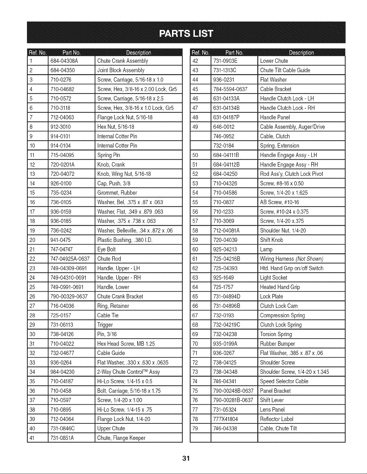
684-04308A ChuteCrankAssembly
2 .684-04350 _ Joint BlockAssembly
3 710-0276 Screw,Carriage,5/16-18x 1.0
4 710-04682 Screw,Hex,3/8-16x 2.00 Lock,Gr5
5 710-0572 Screw,Carriage,5/16-18x 2.5
6 710-3118 Screw,Hex,3/8-16x 1.0Lock,Gr5
7 712-04063 FlangeLockNut,5/16-18
8 912-3010 HexNut,5/16-18
9 914-0101 InternalCotterPin
10 914-0104 InternalCotterPin
11 715-04095 SpringPin
12 720-0201A Knob,Crank
13 720-04072 Knob,WingNut,5/16-18
14 926-0100 Cap,Push,3/8
15 735-0234 Grommet,Rubber
16 736-0105 Washer,Bel,.375x .87x .063
17 936-0159 Washer,Fiat,.349x .879.063
18 936-0185 Washer,.375x .738x .063
19 736-0242 Washer,Belleville,.34x .872x .06
20 941-0475 PlasticBushing,.380 I.D.
21 .747-04747 _Eye Bolt
22 747-04925A-0637 ChuteRod
23 749-04309-0691 Handle,Upper- LH
24 749-04310-0691 Handle,Upper- RH
25 749-0991-0691 Handle,Lower
26 790-00329-0637 ChuteCrankBracket
27 716-04036 Ring,Retainer
28 725-0157 CableTie
29 731-06113 Trigger
30 738-04126 Pin,3/16
31 710-04022 HexHeadScrew,MB 1.25
32 732-04677 CableGuide
33 i 936-0264 FiatWasher,.330x .630x .0635
34 984-04230 2-WayChuteControFMAssy
35 710-04187 Hi-LoScrew,1/4-15x 0.5
36 710-0458 Bolt,Carriage,5/16-18x 1.75
37 710-0597 Screw,1/4-20x 1.00
38 710-0895 Hi-LoScrew,1/4-15x .75
39 712-04064 FlangeLockNut,1/4-20
40 731-0846C UpperChute
41 731-0851A Chute,FlangeKeeper
D _ O
731-0903E LowerChute
43 731-1313C ChuteTiltCableGuide
44 936-0231 FiatWasher
45 784-5594-0637 CableBracket
46 631-04133A HandleClutchLock- LH
47 631-04134B HandleClutchLock- RH
48 631-04187P HandlePanel
49 646-0012 CableAssembly,Auger/Drive
746-0952 Cable,Clutch
732-0184 Spring,Extension
50 684-04111B HandleEngageAssy- LH
51 684-04112B HandleEngageAssy- RH
52 684-04250 RodAss'y,ClutchLockPivot
53 710-04326 Screw,#8-16x 0.50
54 710-04586 Screw,1/4-20x 1.625
55 710-0837 AB Screw,#10-16
56 710-1233 Screw,#10-24x 0.375
57 710-3069 Screw,1/4-20x.375
58 712-04081A ShoulderNut, 1/4-20
59 720-04039 ShiftKnob
60 925-04213 Lamp
61 725-04216B Wiring Harness(Not Shown)
62 725-04393 Htd.HandGripon/off Switch
63 925-1649 LightSocket
64 725-1757 HeatedHandGrip
65 731-04894D LockPlate
66 731-04896B ClutchLockCam
67 732-0193 CompressionSpring
68 732-04219C ClutchLockSpring
69 732-04238 TorsionSpring
70 935-0199A RubberBumper
71 936-0267 FiatWasher,.385x .87x .06
72 738-04125 ShoulderScrew
73 738-04348 ShoulderScrew,1/4-20x 1.345
74 746-04341 SpeedSelectorCable
75 790-00248B-0637 PanelBracket
76 790-00281B-0637 Shift Lever
77 731-05324 LensPanel
78 777X41804 ReflectorLabel
79 746-04338 Cable,ChuteTilt
31
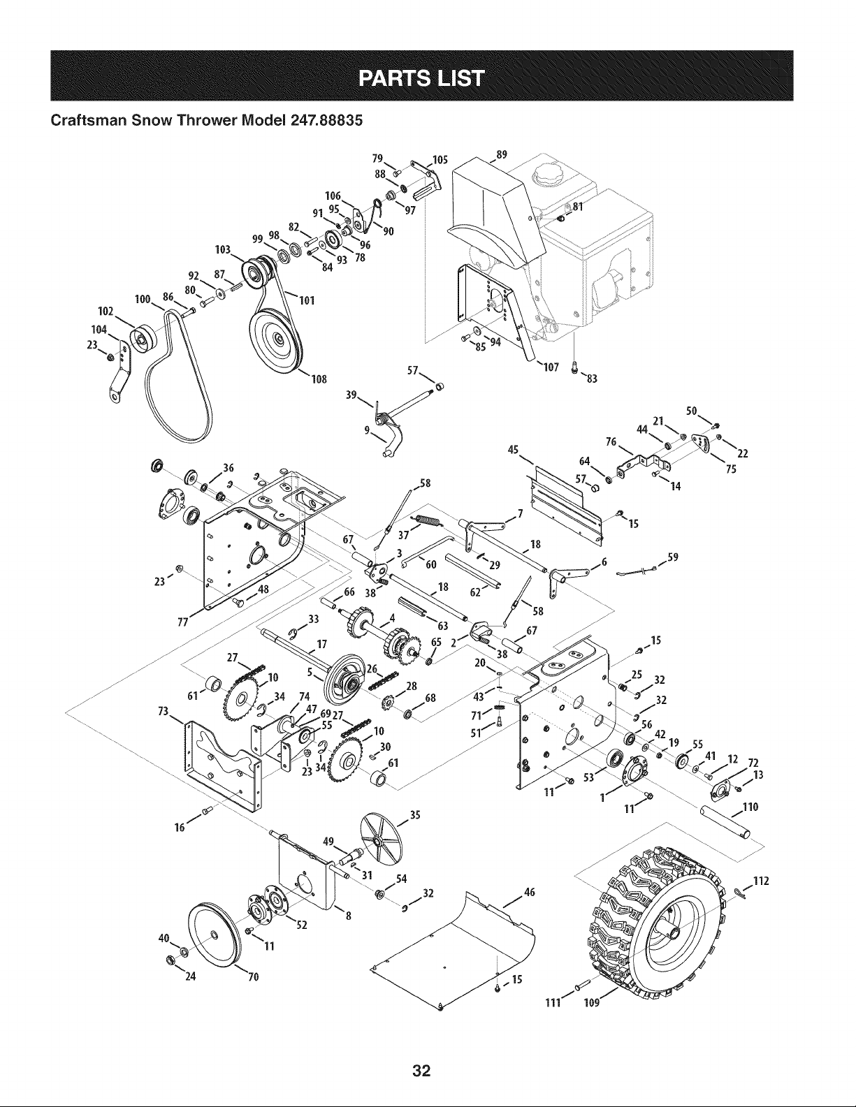
Craftsman Snow Thrower Model 247.88835
106
91
100
102
104
23._
103
92
77
73
4O
24
36
27
11
"93 78
108
33
17
45
/7
18
18
67
28
31 54
_/32
111 10
...........
ii / i
5O
44 21_
14
25 32
32
56
19 55
72
32
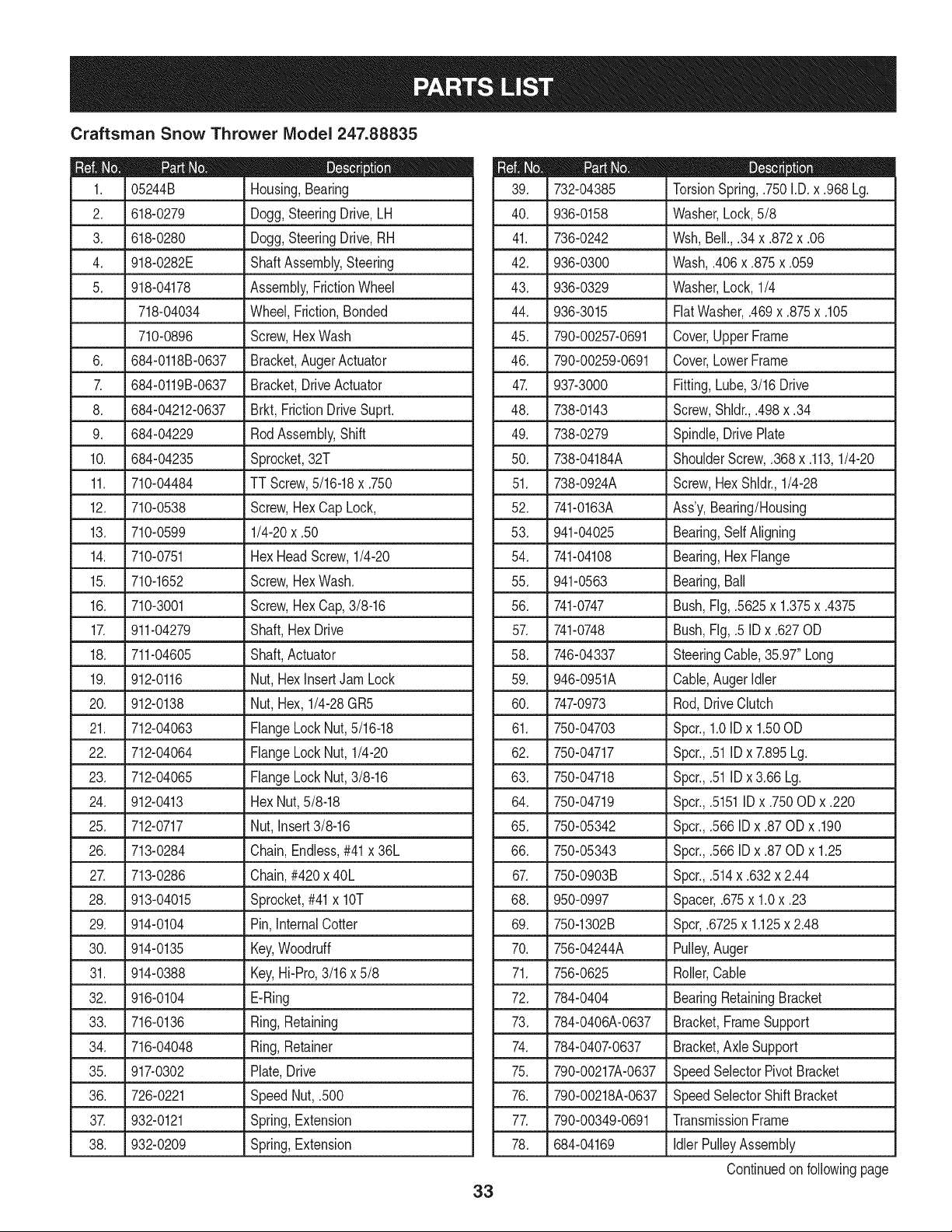
Craftsman Snow Thrower IViodel 247.88835
|= o o
05244B Housing,Bearing
2. 618-0279 Dogg,SteeringDrive,LH
3. 618-0280 Dogg,SteeringDrive,RH
4. 918-0282E ShaftAssembly,Steering
5. 918-04178 Assembly,FrictionWheel
718-04034 Wheel,Friction,Bonded
710-0896 Screw,HexWash
6. 684-0118B-0637 Bracket,AugerActuator
7. 684-0119B-0637 Bracket,DriveActuator
8. 684-04212-0637 Brkt, FrictionDriveSuprt.
9. 684-04229 RodAssembly,Shift
10. 684-04235 Sprocket,32T
11. 710-04484 TT Screw,5/16-18x .750
12. 710-0538 Screw,Hex CapLock,
13. 710-0599 1/4-20x .50
14. 710-0751 HexHeadScrew,1/4-20
15. 710-1652 Screw,HexWash.
16. 710-3001 Screw,Hex Cap,3/8-16
17. 911-04279 Shaft,Hex Drive
18. 711-04605 Shaft,Actuator
19. 912-0116 Nut, HexInsertJamLock
20. 912-0138 Nut, Hex,1/4-28GR5
21. 712-04063 FlangeLockNut,5/16-18
22. 712-04064 FlangeLockNut, 1/4-20
23. 712-04065 FlangeLockNut,3/8-16
24. 912-0413 HexNut,5/8-18
25. 712-0717 Nut, Insert3/8-16
26. 713-0284 Chain,Endless,#41x 36L
27. 713-0286 Chain,#420x 40L
28. 913-04015 Sprocket,#41x lOT
29. 914-0104 Pin,InternalCotter
30. 914-0135 Key,Woodruff
31. 914-0388 Key,Hi-Pro,3/16 x 5/8
32. 916-0104 E-Ring
33. 716-0136 Ring,Retaining
34. 716-04048 Ring,Retainer
35. 917-0302 Plate,Drive
36. 726-0221 SpeedNut, .500
37. 932-0121 Spring,Extension
38. 932-0209 Spring,Extension
33
732-04385
40. 936-0158
41. 736-0242
42. 936-0300
43. 936-0329
44. 936-3015
45. 790-00257-0691
46. 790-00259-0691
4_ 937-3000
48. 738-0143
49. 738-0279
50. 738-04184A
51. 738-0924A
52. 741-0163A
53. 941-04025
54. 741-04108
55. 941-0563
56. 741-0747
57. 741-0748
58. 746-04337
59. 946-0951A
60. 747-0973
61. 750-04703
62. 750-04717
63. 750-04718
64. 750-04719
65. 750-05342
66. 750-05343
67. 750-0903B
68. 950-0997
69. 750-1302B
70. 756-04244A
71. 756-0625
72. 784-0404
73. 784-0406A-0637
D = I
TorsionSpring,.750I.D.x .968 Lg.
Washer,Lock,5/8
Wsh,Bell.,.34x .872x .06
Wash,.406x .875x .059
Washer,Lock,1/4
FiatWasher,.469x .875x .105
Cover,UpperFrame
Cover,LowerFrame
Fitting,Lube,3/16 Drive
Screw,Shldr.,.498x .34
Spindle,DrivePlate
ShoulderScrew,.368x .113,1/4-20
Screw,HexShldr.,1/4-28
Ass'y,Bearing/Housing
Bearing,Self Aligning
Bearing,HexFlange
Bearing,Ball
Bush,Fig,.5625x 1.375x .4375
Bush,Fig,.5 IDx .627OD
SteeringCable,35.97"Long
Cable,AugerIdler
Rod,DriveClutch
Spcr.,1.0IDx 1.50OD
Spcr.,.51IDx 7.895Lg.
Spcr.,.51IDx 3.66Lg.
Spcr.,.5151IDx .750ODx .220
Spcr.,.566IDx .87 ODx .190
Spcr.,.566IDx .87 ODx 1.25
Spcr.,.514x .632x 2.44
Spacer,.675x 1.0x .23
Spcr,.6725x 1.125x 2.48
Pulley,Auger
Roller,Cable
BearingRetainingBracket
Bracket,FrameSupport
4, 784-040_0637
75. 790-00217A-0637
76. 790-00218A-0637
7_ 790-00349-0691
78. 684-04169
Bracket,AxleSupport
SpeedSelectorPivotBracket
SpeedSelectorShiftBracket
TransmissionFrame
IdlerPulleyAssembly
Continuedonfollowingpage
Craftsman Snow Thrower IViodel 247.88835
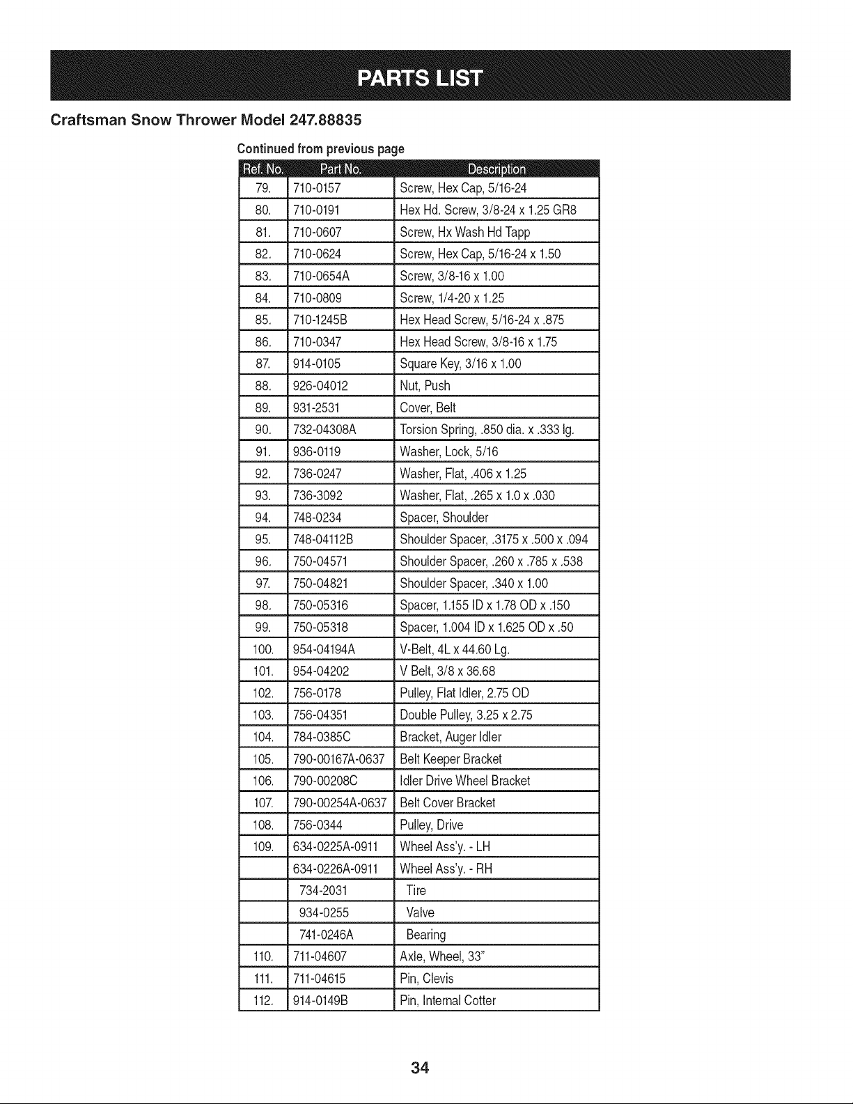
Continuedfrom previouspage
|= 0 =
710-0157 Screw,Hex Cap,5/16-24
80. 710-0191 HexHd.Screw,3/8-24x 1.25GR8
81. 710-0607 Screw,Hx Wash HdTapp
82. 710-0624 Screw,Hex Cap,5/16-24x 1.50
83. 710-0654A Screw,3/8-16x 1.00
84. 710-0809 Screw,1/4-20x 1.25
85. 710-1245B HexHeadScrew,5/16-24x .875
86. 710-0347 HexHeadScrew,3/8-16x 1.75
87. 914-0105 SquareKey,3/16 x 1.00
88. 926-04012 Nut, Push
89. 931-2531 Cover,Belt
90. 732-04308A TorsionSpring,.850dia.x .333 Ig.
91. 936-0119 Washer,Lock,5/16
92. 736-0247 Washer,Flat, .406x 1.25
93. 736-3092 Washer,Flat, .265x 1.0x .030
94. 748-0234 Spacer,Shoulder
95. 748-04112B ShoulderSpacer,.3175x .500x .094
96. 750-04571 ShoulderSpacer,.260x .785x .538
97. 750-04821 ShoulderSpacer,.340x 1.00
98. 750-05316 Spacer,1.155IDx 1.78ODx .150
99. 750-05318 Spacer,1.004IDx 1.625ODx .50
100. 954-04194A V-Belt,4Lx44.60 Lg.
101. 954-04202 V Belt,3/8 x 36.68
102. 756-0178 Pulley,FlatIdler,2.75OD
103. 756-04351 DoublePulley,3.25x 2.75
104. 784-0385C Bracket,Auger Idler
105. 790-00167A-0637 Belt KeeperBracket
106. 790-00208C Idler DriveWheel Bracket
107. 790-00254A-0637 BeltCoverBracket
108. 756-0344 Pulley,Drive
109. 634-0225A-0911 WheelAss'y.- LH
634-0226A-0911 WheelAss'y.- RH
734-2031 Tire
934-0255 Valve
741-0246A Bearing
110. 711-04607 Axle,Wheel,33"
111. 711-04615 Pin,Clevis
112. 914-0149B Pin,InternalCotter
34
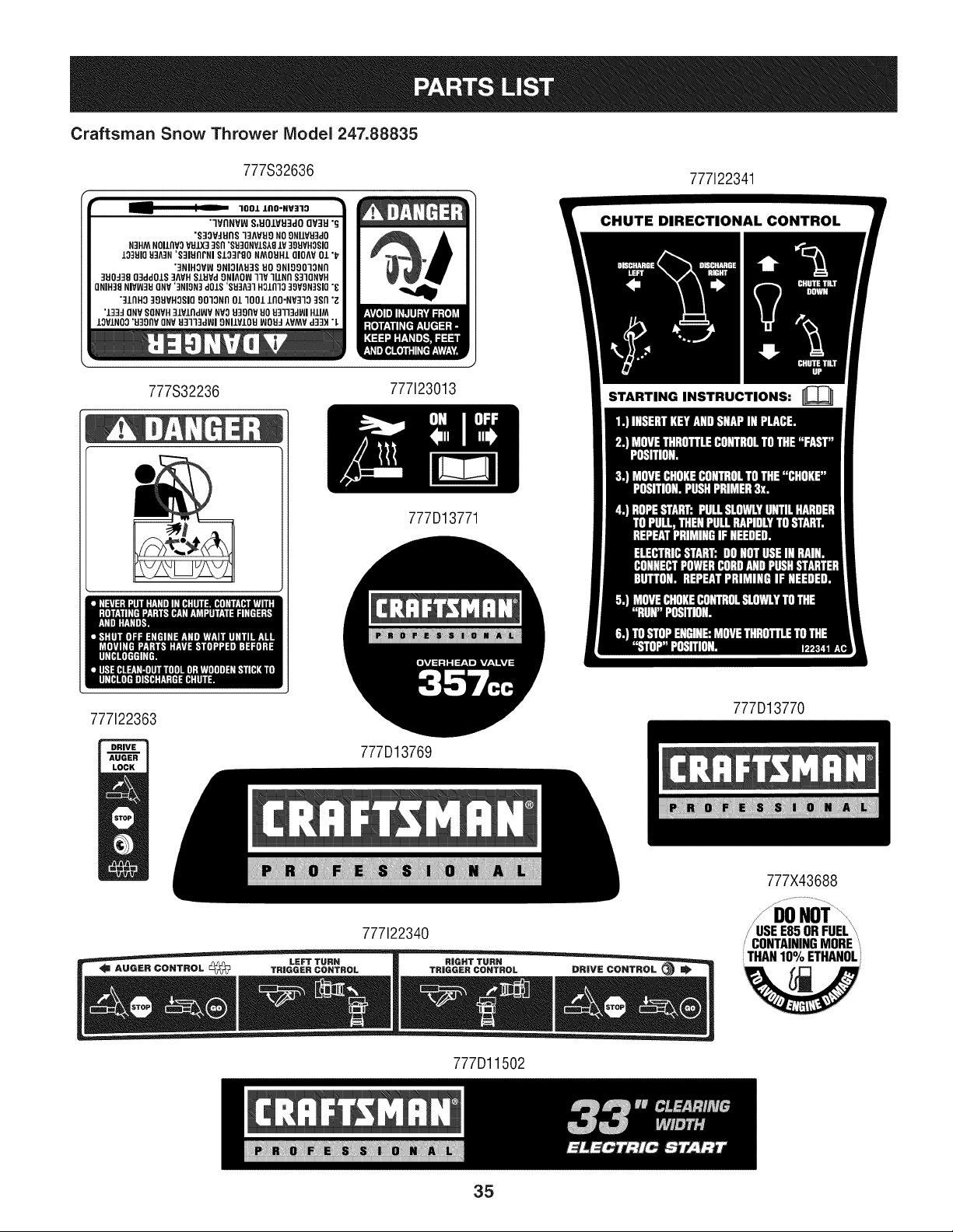
Craftsman Snow Thrower Model 247.88835
777S32636
777122341
777S32236
777123013
STARTING INSTRUCTIONS:
777D13771
777122363
777D13769
777D13770
777X43688
777122340
/ I
/' USEE85ORFUEL"
/ CONTAININGMORE
THAN10% ETHANOL
'W
777Dl1502
35
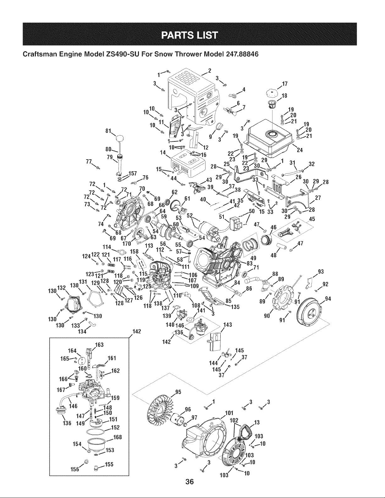
Craftsman Engine Model ZS490=SU For Snow Thrower Model 247.88846
10
170'
114
124122121_ 15
\_ \ 117.116,
123:
10,
14
62
40\_
51
9 48
[71
88
163
164
161
/
167/
\
136
118
\ 85
/86
148146 143
32
29 28
27
8
45
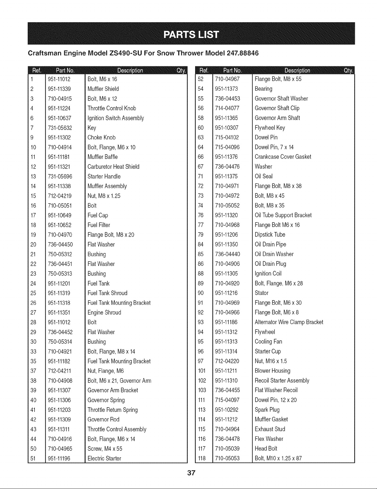
Craftsman Engine IViodel ZS490-SU For Snow Thrower IViodel 247.88846
m
1
2
3
4
6
7
9
10
11
12
13
14
15
16
17
18
19
2O
21
22
23
24
25
26
27
28
29
30
33
35
37
38
39
40
41
42
43
44
50
51
951-11012
951-11339
710-04915
951-11224
951-10637
731-05632
951-11302
710-04914
951-11181
951-11321
731-05696
951-11338
712-04219
710-05051
951-10649
951-10652
710-04970
736-04450
750-05312
736-04451
750-05313
951-11201
951-11319
951-11318
951-11351
951-11012
736-04452
750-05314
710-04921
951-11182
712-04211
710-04908
951-11307
951-11306
951-11203
951-11309
951-11311
710-04916
710-04965
951-11196
|= o o e
Bolt,M6x 16
MufflerShield
Bolt,M6x 12
ThrottleControlKnob
IgnitionSwitchAssembly
Key
ChokeKnob
Bolt,Flange,M6x 10
MufflerBaffle
CarburetorHeatShield
StarterHandle
MufflerAssembly
Nut, M8x 1.25
Bolt
FuelCap
FuelFilter
FlangeBolt,M8x 20
FlatWasher
Bushing
FlatWasher
Bushing
FuelTank
FuelTankShroud
FuelTankMountingBracket
EngineShroud
Bolt
FlatWasher
Bushing
Bolt,Flange,M8x 14
FuelTankMountingBracket
Nut, Flange,M6
Bolt,M6x 21,GovernorArm
GovernorArm Bracket
GovernorSpring
ThrottleReturnSpring
GovernorRod
ThrottleControlAssembly
Bolt,Flange,M6x 14
Screw,M4 x 55
ElectricStarter
m
52
54
55
56
58
6O
63
64
66
67
71
72
73
74
76
77
79
84
85
86
88
89
90
91
92
93
94
95
96
97
101
102
103
111
113
114
115
116
117
118
710-04967
951-11373
736-04453
714-04077
951-11365
951-10307
715-04102
715-04096
951-11376
736-04476
951-11375
710-04971
710-04972
710-05052
951-11320
710-04968
951-11206
951-11350
736-04440
710-04906
951-11305
710-04920
951-11216
710-04969
710-04966
951-11186
951-11312
951-11313
951-11314
712-04220
951-11211
951-11310
736-04455
715-04097
951-10292
951-11212
710-04964
736-04478
710-05039
710-05053
|= 0 = e
FlangeBolt, M8 x 55
Bearing
GovernorShaftWasher
GovernorShaft Clip
GovernorArmShaft
FlywheelKey
DowelPin
DowelPin,7 x 14
CrankcaseCoverGasket
Washer
OilSeal
FlangeBolt, M8 x 38
Bolt,M8x 45
Bolt,M8x 35
OilTubeSupportBracket
FlangeBolt M6x 16
DipstickTube
OilDrainPipe
OilDrainWasher
OilDrainPlug
IgnitionCoil
Bolt,Flange,M6 x 28
Stator
FlangeBolt, M6 x 30
FlangeBolt, M6 x 8
AlternatorWire ClampBracket
Flywheel
CoolingFan
StarterCup
Nut,M16x 1.5
BlowerHousing
RecoilStarterAssembly
FlatWasherRecoil
DowelPin,12x 20
SparkPlug
MufflerGasket
ExhaustStud
FlexWasher
HeadBolt
Bolt,MIOx 1.25x 87
37
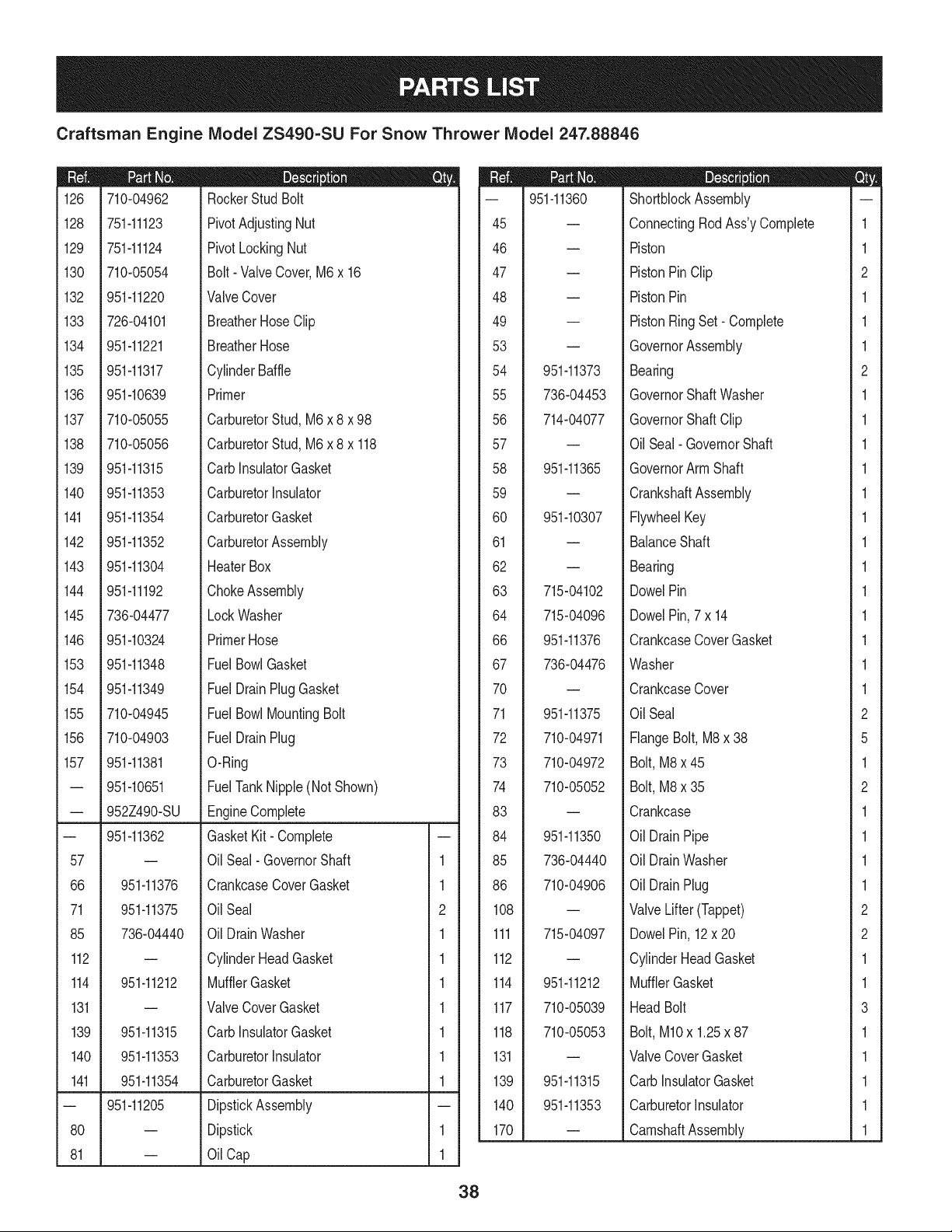
Craftsman Engine IViodel ZS490-SU For Snow Thrower IViodel 247.88846
|= 0 o e
126 710-04962 RockerStud Bolt
128 751-11123 PivotAdjustingNut
129 751-11124 Pivot LockingNut
130 710-05054 Bolt- ValveCover,M6x 16
132 951-11220 ValveCover
133 726-04101 BreatherHoseClip
134 951-11221 BreatherHose
135 951-11317 CylinderBaffle
136 951-10639 Primer
137 710-05055 CarburetorStud, M6 x 8 x 98
138 710-05056 CarburetorStud, M6 x 8 x 118
139 951-11315 CarbInsulatorGasket
140 951-11353 CarburetorInsulator
141 951-11354 CarburetorGasket
142 951-11352 CarburetorAssembly
143 951-11304 HeaterBox
144 951-11192 ChokeAssembly
145 736-04477 Lock Washer
146 951-10324 PrimerHose
153 951-11348 FuelBowlGasket
154 951-11349 FuelDrainPlug Gasket
155 710-04945 FuelBowl MountingBolt
156 710-04903 FuelDrainPlug
157 951-11381 O-Ring
-- 951-10651 FuelTankNipple(NotShown)
-- 952Z490-SU EngineComplete
-- 951-11362 GasketKit- Complete
57 -- Oil Seal- GovernorShaft 1
66 951-11376 CrankcaseCoverGasket 1
71 951-11375 OilSeal 2
85 736-04440 Oil DrainWasher 1
112 -- CylinderHeadGasket 1
114 951-11212 MufflerGasket 1
131 -- ValveCoverGasket 1
139 951-11315 CarbInsulatorGasket 1
140 951-11353 CarburetorInsulator 1
141 951-11354 CarburetorGasket 1
-- 951-11205 DipstickAssembly
80 -- Dipstick 1
81 -- Oil Cap 1
m
45
46
47
48
49
53
54
55
56
57
58
59
6O
61
62
63
64
66
67
7O
71
72
73
74
83
84
85
86
108
111
112
114
117
118
131
139
140
170
951-11360
951-11373
736-04453
714-04077
951-11365
951-10307
715-04102
715-04096
951-11376
736-04476
951-11375
710-04971
710-04972
710-05052
951-11350
736-04440
710-04906
715-04097
951-11212
710-05039
710-05053
951-11315
951-11353
D = Q O
ShortblockAssembly
ConnectingRodAss'yComplete
Piston
PistonPinClip
PistonPin
PistonRingSet- Complete
GovernorAssembly
Bearing
GovernorShaftWasher
GovernorShaft Clip
OilSeal- GovernorShaft
GovernorArmShaft
CrankshaftAssembly
FlywheelKey
BalanceShaft
Bearing
DowelPin
DowelPin,7 x 14
CrankcaseCoverGasket
Washer
CrankcaseCover
OilSeal
FlangeBolt, M8 x 38
Bolt,M8x 45
Bolt,M8x 35
Crankcase
OilDrainPipe
OilDrainWasher
OilDrainPlug
ValveLifter(Tappet)
DowelPin, 12x 20
CylinderHeadGasket
MufflerGasket
HeadBolt
Bolt,M10x 1.25x 87
ValveCoverGasket
CarbInsulatorGasket
CarburetorInsulator
CamshaftAssembly
1
1
2
1
1
1
2
1
1
1
1
1
1
1
1
1
1
1
1
1
2
5
1
2
1
1
1
1
2
2
1
1
3
1
1
1
1
1
38
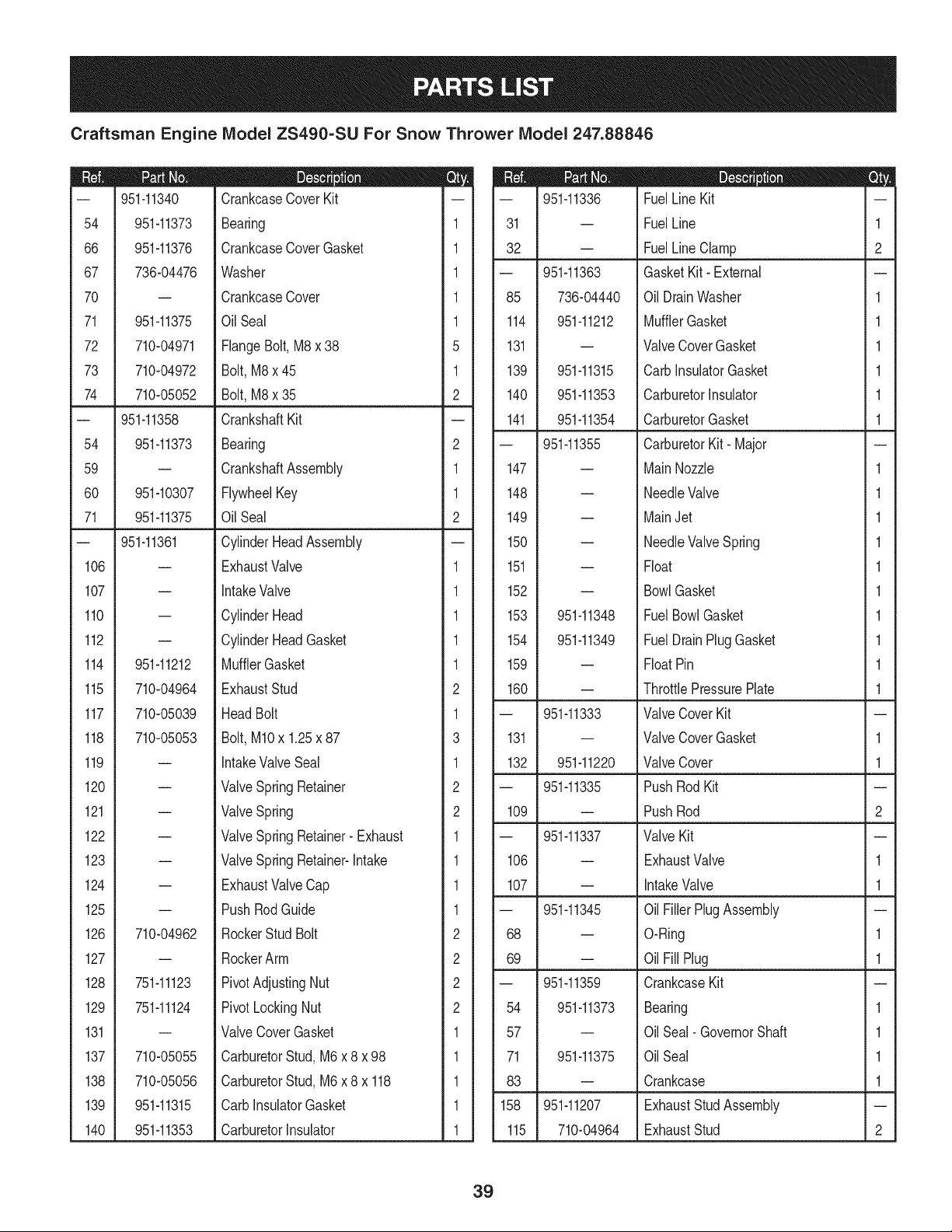
Craftsman Engine IViodel ZS490=SU For Snow Thrower IViodel 247.88846
I = O O
-- 951-11340 CrankcaseCoverKit
54 951-11373 Bearing 1
66 951-11376 CrankcaseCoverGasket 1
67 736-04476 Washer 1
70 -- CrankcaseCover 1
71 951-11375 Oil Seal 1
72 710-04971 FlangeBolt,M8x 38 5
73 710-04972 Bolt,M8x 45 1
74 710-05052 Bolt,M8x 35 2
-- 951-11358 CrankshaftKit
54 951-11373 Bearing 2
59 -- CrankshaftAssembly 1
60 951-10307 FlywheelKey 1
71 951-11375 Oil Seal 2
-- 951-11361 CylinderHeadAssembly
106 -- ExhaustValve 1
107 -- IntakeValve 1
110 -- CylinderHead 1
112 -- CylinderHeadGasket 1
114 951-11212 MufflerGasket 1
115 710-04964 ExhaustStud 2
117 710-05039 HeadBolt 1
118 710-05053 Bolt,MlOx 1.25x 87 3
119 -- IntakeValveSeal 1
120 -- ValveSpring Retainer 2
121 -- ValveSpring 2
122 -- ValveSpring Retainer- Exhaust 1
123 -- ValveSpring Retainer-Intake 1
124 -- ExhaustValveCap 1
125 -- PushRodGuide 1
126 710-04962 RockerStud Bolt 2
127 -- RockerArm 2
128 751-11123 PivotAdjustingNut 2
129 751-11124 PivotLockingNut 2
131 -- ValveCoverGasket 1
137 710-05055 CarburetorStud,M6 x 8 x 98 1
138 710-05056 CarburetorStud,M6 x 8 x 118 1
139 951-11315 CarbInsulatorGasket 1
140 951-11353 CarburetorInsulator 1
D = O
-- 951-11336 FuelLineKit
31 -- FuelLine 1
32 -- FuelLine Clamp 2
-- 951-11363 GasketKit- External
85 736-04440 OilDrainWasher 1
114 951-11212 MufflerGasket 1
131 -- ValveCoverGasket 1
139 951-11315 CarbInsulatorGasket 1
140 951-11353 CarburetorInsulator 1
141 951-11354 CarburetorGasket 1
-- 951-11355 CarburetorKit- Major
147 -- MainNozzle 1
148 -- NeedleValve 1
149 -- MainJet 1
150 -- NeedleValveSpring 1
151 -- Float 1
152 -- BowlGasket 1
153 951-11348 FuelBowlGasket 1
154 951-11349 FuelDrainPlugGasket 1
159 -- FloatPin 1
160 -- ThrottlePressurePlate 1
-- 951-11333 ValveCoverKit
131 -- ValveCoverGasket 1
132 951-11220 ValveCover 1
-- 951-11335 PushRodKit
109 -- PushRod 2
-- 951-11337 ValveKit
106 -- ExhaustValve 1
107 -- IntakeValve 1
-- 951-11345 OilFillerPlugAssembly
68 -- O-Ring 1
69 -- Oil Fill Plug 1
-- 951-11359 CrankcaseKit
54 951-11373 Bearing 1
57 -- Oil Seal- GovernorShaft 1
71 951-11375 OilSeal 1
83 -- Crankcase 1
158 951-11207 ExhaustStudAssembly
115 710-04964 ExhaustStud 2
39
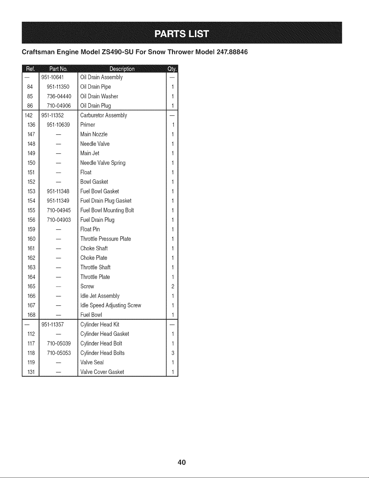
Craftsman Engine IViodel ZS490=SU For Snow Thrower IViodel 247.88846
m = O O
-- 951-10641 Oil DrainAssembly
84 951-11350 Oil DrainPipe 1
85 736-04440 Oil DrainWasher 1
86 710-04906 Oil DrainPlug 1
142 951-11352 CarburetorAssembly
136 951-10639 Primer 1
147 -- MainNozzle 1
148 -- NeedleValve 1
149 -- MainJet 1
150 -- NeedleValveSpring 1
151 -- Float 1
152 -- BowlGasket 1
153 951-11348 FuelBowlGasket 1
154 951-11349 FuelDrain PlugGasket 1
155 710-04945 FuelBowl MountingBolt 1
156 710-04903 FuelDrain Plug 1
159 -- FloatPin 1
160 -- ThrottlePressurePlate 1
161 -- ChokeShaft 1
162 -- ChokePlate 1
163 -- ThrottleShaft 1
164 -- ThrottlePlate 1
165 -- Screw 2
166 -- Idle Jet Assembly 1
167 -- Idle SpeedAdjustingScrew 1
168 -- FuelBowl 1
-- 951-11357 CylinderHeadKit
112 -- CylinderHeadGasket 1
117 710-05039 CylinderHeadBolt 1
118 710-05053 CylinderHeadBolts 3
119 -- ValveSeal 1
131 -- ValveCoverGasket 1
4O

41
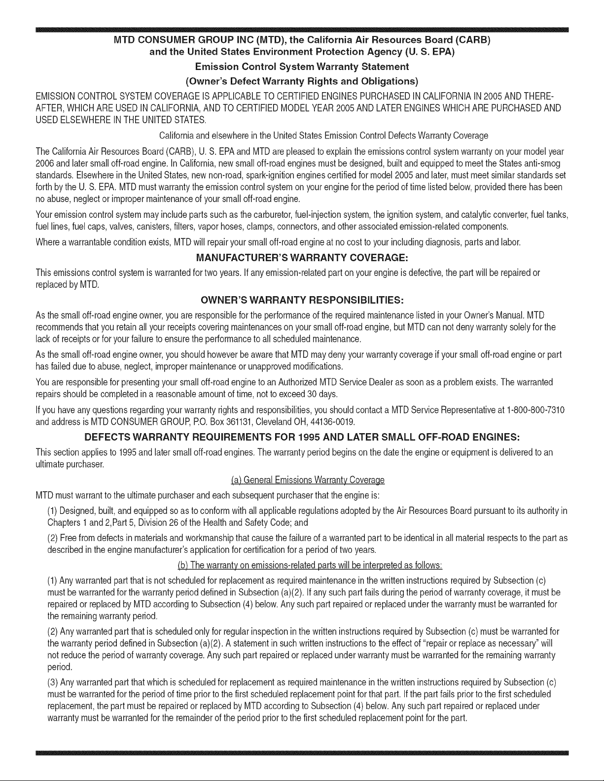
MTD CONSUMER GROUP INC (MTD), the California Air Resources Board (CARB)
and the United States Environment Protection Agency (U. S. EPA)
Emission Control System Warranty Statement
(Owner's Defect Warranty Rights and Obligations)
EMISSIONCONTROLSYSTEMCOVERAGEIS APPLICABLETOCERTIFIEDENGINESPURCHASEDIN CALIFORNIAIN2005ANDTHERE-
AFTER,WHICHARE USEDIN CALIFORNIA,ANDTO CERTIFIEDMODELYEAR2005 AND LATERENGINESWHICHARE PURCHASEDAND
USEDELSEWHEREINTHEUNITEDSTATES.
Californiaandelsewherein the UnitedStatesEmissionControlDefectsWarrantyCoverage
The CaliforniaAir ResourcesBoard(CARB),U. S. EPAand MTDare pleasedto explaintheemissionscontrolsystemwarrantyonyour modelyear
2006andlatersmalloff-roadengine.In California,new smalloff-roadenginesmustbe designed,builtand equippedto meet theStatesanti-smog
standards.Elsewhereinthe UnitedStates,newnon-road,spark-ignitionenginescertifiedfor model2005and later,mustmeetsimilarstandardsset
forthby the U.S. EPA.MTDmustwarrantythe emissioncontrolsystemon yourenginefor the periodof time listed below,providedtherehasbeen
noabuse,neglector impropermaintenanceof your smalloff-roadengine.
Youremissioncontrolsystemmayincludepartssuchas the carburetor,fuel-injectionsystem,the ignitionsystem,andcatalyticconverter,fueltanks,
fuel lines,fuel caps,valves,canisters,filters,vaporhoses,clamps,connectors,andotherassociatedemission-relatedcomponents.
Wherea warrantableconditionexists,MTDwill repairyoursmalloff-roadengineat nocost to yourincludingdiagnosis,partsand labor.
MANUFACTURER'S WARRANTY COVERAGE:
Thisemissionscontrolsystemis warrantedfor two years.If anyemission-relatedpart onyourengineis defective,the part will be repairedor
replacedby MTD.
OWNER'S WARRANTY RESPONSIBILITIES:
As the smalloff-roadengineowner,youare responsibleforthe performanceof the requiredmaintenancelisted in your Owner'sManual.MTD
recommendsthatyou retainall yourreceiptscoveringmaintenanceson yoursmalloff-roadengine,but MTDcan not denywarrantysolelyfor the
lackof receiptsor foryour failureto ensurethe performanceto all scheduledmaintenance.
As the smalloff-roadengineowner,youshouldhoweverbeawarethat MTDmaydenyyour warrantycoverageif yoursmall off-roadengine or part
hasfaileddue toabuse, neglect,impropermaintenanceor unapprovedmodifications.
Youare responsiblefor presentingyour smalloff-roadengineto an AuthorizedMTDServiceDealeras soonas a problemexists.Thewarranted
repairsshouldbe completedin a reasonableamountof time,notto exceed30 days.
Ifyou haveanyquestionsregardingyourwarrantyrightsand responsibilities,you shouldcontacta MTDServiceRepresentativeat 1-800-800-7310
andaddressis MTDCONSUMERGROUP,RO. Box361131,ClevelandOH,44136-0019.
DEFECTS WARRANTY REQUIREMENTS FOR 1995 AND LATER SMALL OFF-ROAD ENGINES:
Thissectionappliesto 1995and later smalloff-roadengines.The warrantyperiodbeginsonthe datethe engineor equipmentis deliveredto an
ultimatepurchaser.
(a) GeneralEmissionsWarrantyCoverage
MTDmustwarrantto the ultimatepurchaserand eachsubsequentpurchaserthatthe engineis:
(1)Designed,built,and equippedsoas to conformwithallapplicableregulationsadoptedby the AirResourcesBoardpursuantto itsauthorityin
Chapters1 and 2,Part 5, Division26of the HealthandSafetyCode;and
(2) Freefromdefectsin materialsandworkmanshipthatcausethe failureof a warrantedpart to be identicalin all materialrespectsto the partas
describedin theengine manufacturer'sapplicationfor certificationfora periodof two years.
(b)The warrantyon emissions-relatedpartswill be interpretedas follows:
(1)Anywarrantedpart thatis not scheduledfor replacementas requiredmaintenancein the writteninstructionsrequiredby Subsection(c)
mustbewarrantedfor the warrantyperioddefinedin Subsection(a)(2). Ifany suchpartfailsduringthe periodof warrantycoverage,it mustbe
repairedor replacedby MTDaccordingto Subsection(4) below.Anysuch part repairedor replacedunder thewarrantymustbe warrantedfor
the remainingwarrantyperiod.
(2)Any warrantedpartthat is scheduledonlyfor regularinspectioninthe writteninstructionsrequiredby Subsection(c) must bewarrantedfor
thewarrantyperioddefinedin Subsection(a)(2).A statementin such writteninstructionsto the effectof "repairor replaceas necessary"will
not reducethe periodof warrantycoverage.Anysuch part repairedor replacedunderwarrantymustbe warrantedforthe remainingwarranty
period.
(3) Anywarrantedpartthat whichis scheduledfor replacementas requiredmaintenancein the writteninstructionsrequiredby Subsection(c)
mustbewarrantedfor the periodof timepriorto the first scheduledreplacementpointforthat part.Ifthe part failspriorto thefirst scheduled
replacement,the part mustbe repairedor replacedby MTDaccordingto Subsection(4) below.Any suchpart repairedor replacedunder
warrantymustbe warrantedfor the remainderof the periodpriorto the first scheduledreplacementpointfor the part.
(4)Repairorreplacementofanywarrantedpartunderthewarrantyprovisionsofthisarticlemustbeperformedatnochargetotheownerata
warrantystation.
(5)NotwithstandingtheprovisionsofSubsection(4)above,warrantyservicesorrepairsmustbeprovidedatallMTDdistributioncentersthat
arefranchisedtoservicethesubjectengines.
(6)Theownermustnotbechargedfordiagnosticlaborthatleadstothedeterminationthatawarrantedpartisinfactdefective,providedthat
suchdiagnosticworkisperformedatawarrantystation.
(7)Theenginemanufacturerisliablefordamagestootherenginecomponentsproximatelycausedbyafailureunderwarrantyofanywarranted
part.
(8)Throughouttheengine'swarrantyperioddefinedinSubsection(a)(2),MTDwillmaintainasupplyofwarrantedpartssufficienttomeetthe
expecteddemandforsuchparts.
(9)Anyreplacementpartmaybeusedintheperformanceofanywarrantymaintenanceorrepairsandmustbeprovidedwithoutchargetothe
owner.SuchusewillnotreducethewarrantyobligationsofMTD.
(10)Add-onormodifiedpartsthatarenotexemptedbytheAirResourcesBoardmaynotbeused.Theuseofanynon-exemptedadd-onor
modifiedpartsshallbegroundsfordisallowingawarrantyclaimmadeinaccordancewiththisarticle.Theenginemanufacturershallnotbe
liableunderthisarticletowarrantfailuresofwarrantedpartscausedbytheuseofnon-exemptedadd-onormodifiedpart.
(c) MTDwill includea copyof the followingemissionwarrantypartslistwitheach newengine,usingthoseportionsof the listapplicableto the
e__&gine.
(1)FuelMeteringSystem
• Coldstart enrichmentsystem(soft choke)
,,Carburetorandinternalparts
• Fuel Pump
• FuelTank
(2)Air InductionSystem
• Aircleaner
• Intakemanifold
(3) IgnitionSystem
• Sparkplug(s)
• MagnetoIgnitionSystem
(4)ExhaustSystem
Catalyticconverter
• SAI (Reedvalve)
(5) MiscellaneousItemsUsedin AboveSystem
Vacuum,temperature, position,timesensitivevalvesand switches
Connectorsandassemblies
(6) Evaporativecontrol
• Fuel Hosecertifiedfor ARBevaporativeemissionof 2006.
• Fuel HoseClamps
Tetheredfuel cap
Carboncanister
Vaporlines
GD0C-100174Rev.B
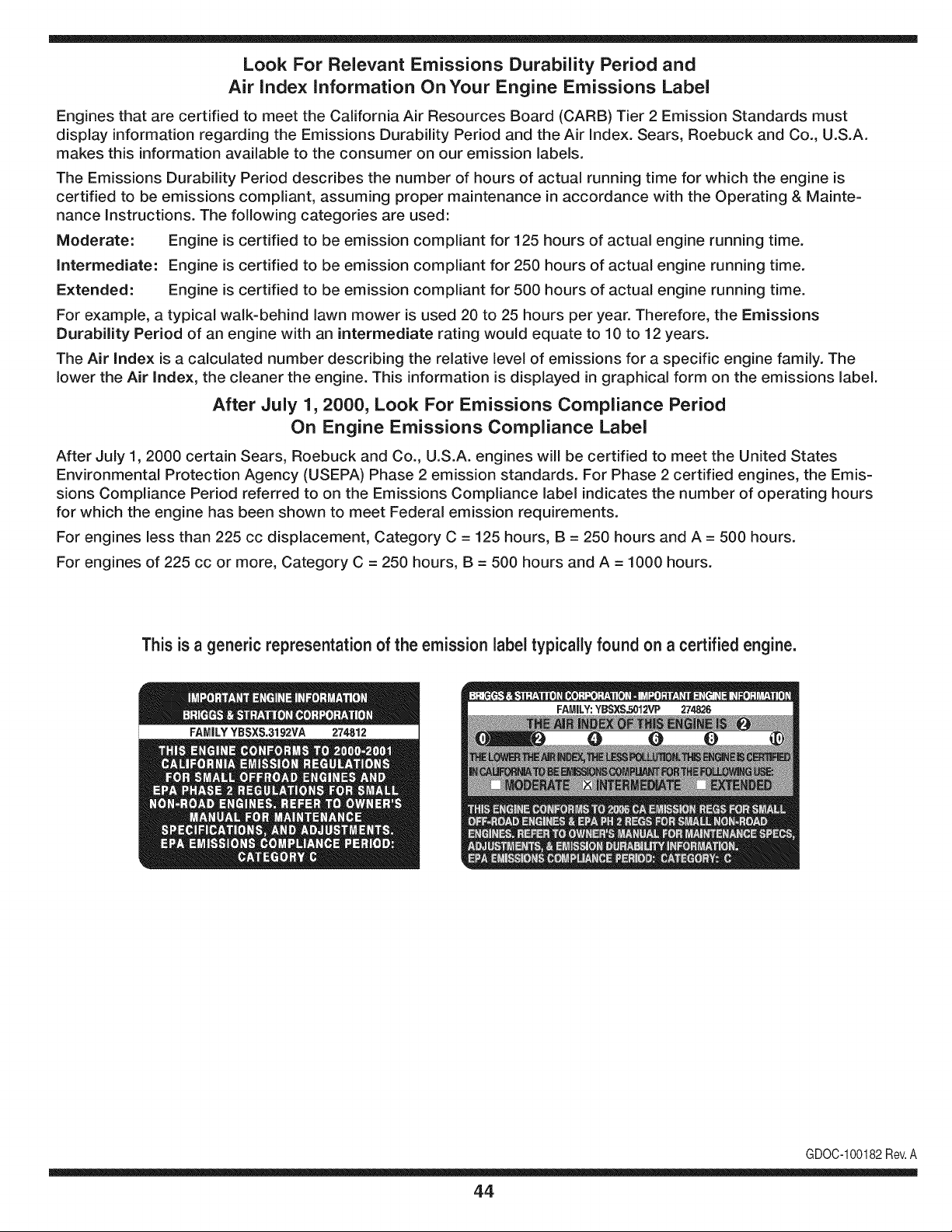
Look For Relevant Emissions Durability Period and
Air index information On Your Engine Emissions Label
Engines that are certified to meet the California Air Resources Board (CARB) Tier 2 Emission Standards must
display information regarding the Emissions Durability Period and the Air Index. Sears, Roebuck and Co., U.S.A.
makes this information available to the consumer on our emission labels.
The Emissions Durability Period describes the number of hours of actual running time for which the engine is
certified to be emissions compliant, assuming proper maintenance in accordance with the Operating & Mainte-
nance Instructions. The following categories are used:
Moderate: Engine is certified to be emission compliant for 125 hours of actual engine running time.
Intermediate: Engine is certified to be emission compliant for 250 hours of actual engine running time.
Extended: Engine is certified to be emission compliant for 500 hours of actual engine running time.
For example, a typical walk-behind lawn mower is used 20 to 25 hours per year. Therefore, the Emissions
Durability Period of an engine with an intermediate rating would equate to 10 to 12 years.
The Air Index is a calculated number describing the relative level of emissions for a specific engine family. The
lower the Air Index, the cleaner the engine. This information is displayed in graphical form on the emissions label.
After July 1,2000, Look For Emissions Compliance Period
On Engine Emissions Compliance Label
After July 1, 2000 certain Sears, Roebuck and Co., U.S.A. engines will be certified to meet the United States
Environmental Protection Agency (USEPA) Phase 2 emission standards. For Phase 2 certified engines, the Emis-
sions Compliance Period referred to on the Emissions Compliance label indicates the number of operating hours
for which the engine has been shown to meet Federal emission requirements.
For engines less than 225 cc displacement, Category C = 125 hours, B = 250 hours and A = 500 hours.
For engines of 225 cc or more, Category C = 250 hours, B = 500 hours and A = 1000 hours.
This is a generic representation of the emission label typically found on a certified engine.
FAMILYYBSXS.3192VA 274812
GDOC-100182Rev.A
44
Congratulationson makinga smart purchase.YournewCraftsman®
productis designedand manufacturedfor yearsof dependableopera-
tion.But likeall products,it mayrequirerepairfrom time to time.That's
whenhavinga RepairProtectionAgreementcan saveyoumoneyand
aggravation.
Here'swhatthe RepairProtectionAgreement*includes:
* Expert service byour 10,000professionalrepairspecialists
* Unlimited service and no charge for partsand laboron all
coveredrepairs
* Product replacement upto $1500ifyourcoveredproductcan't be
fixed
* Discountof 10%from regularpriceof serviceand relatedinstalled
partsnotcoveredby theagreement;also, 10%off regularpriceof
preventivemaintenancecheck
* Fast help by phone- we call itRapidResolution- phone support
froma Searsrepresentative.Thinkof usas a "talkingowner's
manual."
Once youpurchasethe Agreement,a simplephonecall isall that it
takesfor youto scheduleservice.Youcan call anytimedayor night,or
schedulea serviceappointmentonline.
The RepairProtectionAgreementisa risk-freepurchase.Ifyou cancel
for any reasonduringthe productwarrantyperiod,wewill providea full
refund.Or,a proratedrefundanytimeafterthe productwarrantyperiod
expires.Purchaseyour RepairProtectionAgreementtoday!
Some limitations and exclusionsapply. For prices and additional
informationin the U.S.A.call 1-800-827-8855.
*Coverage inCanadavaries on some items.For full details call
Sears Canada at 1-800-381-8665.
Sears Installation Service
ForSearsprofessionalinstallationof homeappliances,garagedoor
openers,waterheaters,and othermajorhomeitems,in the U.S.A.or
Canadacall 1-800-4-MY-HOME®.
45
Declaraci6n de garantia ............................ Pagina 46
Practicas operaci6n seguras ..................... Pagina 47
Montaje ...................................................... Pagina 49
Operaci6n .................................................. Pagina 54
Servicio y Mantenimiento .......................... Pagina 59
Almacenamiento fuera de temporada ....... Pagina 67
Soluci6n de problemas .............................. Pagina 68
Etiquetas de seguridad .............................. Pagina 7
Lista de piezas ........................................... Pagina 28
Acuerdo de protecci6n para reparaciones .... Pagina 75
NOmero de servicio ................................... atras pagina
CRAFTSMAN PROFESIONAL COMPLETA GARANTIA
Cuandosonoperadosy mantenidosdeacuerdoconlasinstruccionessuministradasensutotalidad,siestoArtesanoProfesionalnievelanzadorfalladebido
aundefectodematerialomanodeobradentrode dosa_osa partirdela fechade compra,Ilameal 1-800-4-MY-HOME(1-800-469-4663)paraorganizarde
formagratuitaenlacasadereparaci6n(sila reparaci6no la sustituci6nresulteimposible).
Estagaranfiaseaplicas61oparauna6oa partirdelafechadecomprasi esteproductoesusadoparaprop6sitoscomercialeso dealquiler.
Estagaranfias61ocubredefectosdematerialy manodeobra.SearsnopagarApot:
• Loselernentosque se desgastanduranteel uso normal,incluyendoperono lirnitadoa hojasbarrenao rernos,los cortadoresde deriva,
zapatosantideslizantes,afeitarsela placa,los pinesde cizalla,buj[as,filtrode aire,cinturones,y filtro de aceite.
• Norrnade serviciosde rnantenirniento,carnbiosde aceite,o afinaci6n.
• Carnbiode neurnAticosde sustituci6no reparaci6nde pinchazoscausadosporobjetosdesdeelexterior,talescomoclavos,espinas,
tocones,o de vidrio.
• Carnbiode neurn_ticoso ruedasde reernplazoo la reparaci6ncornoconsecuenciade desgastenormal,accidente,o de larnalaoperaci6n
o rnantenirniento.
• Las reparacionesnecesariasdebidoa los abusosdeloperador,incluyendoperono lirnitadoa los da_oscausadosporel excesode
velocidaddel motor,ode objetosque irnpactandoblarla barrena,el chasiso cigOe_al.
• Las reparacionesnecesariasdebidoa la negligenciadel operador,incluyendopero no lirnitadoa, productosel_ctricosy rnec_nicosde
los da_oscausadosporalrnacenarnientoinadecuado,faltade utilizaci6nde la categoriaapropiaday lacantidadde aceitede motor,o el
fracasopara rnantenerel equipode acuerdoconlas instruccionescontenidasen elmanualdeloperador.
• Motor(sistemade combustible),la lirnpiezao reparacionescausadasporlos combustiblesdecididaa ser contarninadoso oxidado(rancio).
Engeneral,el combustibledebeser utilizadodentrode los30 dias siguientesa su fechade cornpra.
• normaldesgastey deteriorode los acabadosexteriores,o laetiquetadel productode reernplazo.
Estagaranfias61oseaplicamientrasqueesteproductoestAdentrodelosEstadosUnidos.
Estagaranfialeotorgaderechoslegalesespecfficos,y ustedtambienpuedetenetotrosderechosquevat[andeestadoa estado.
Sears, Roebuck and Co., Hoffman Estates, IL 60179
Tipodeaceitedelmotor:
Capacidadde aceitedel motor:
Capacidadde combustible:
Bujias:
Separaci6nde las bujias:
5W-30
37onzas
5cuartos
TorchF6RTC(951-10292)
.020"to .030"
NSrnerode rnodelo ..........................................................
N_mero de serie ..............................................................
Fechade compra .............................................................
Registrearribael nOrnerodel rnodelo,el nOrnerode seriey la fecha
de cornpra
© Sears Brands,LLC
46
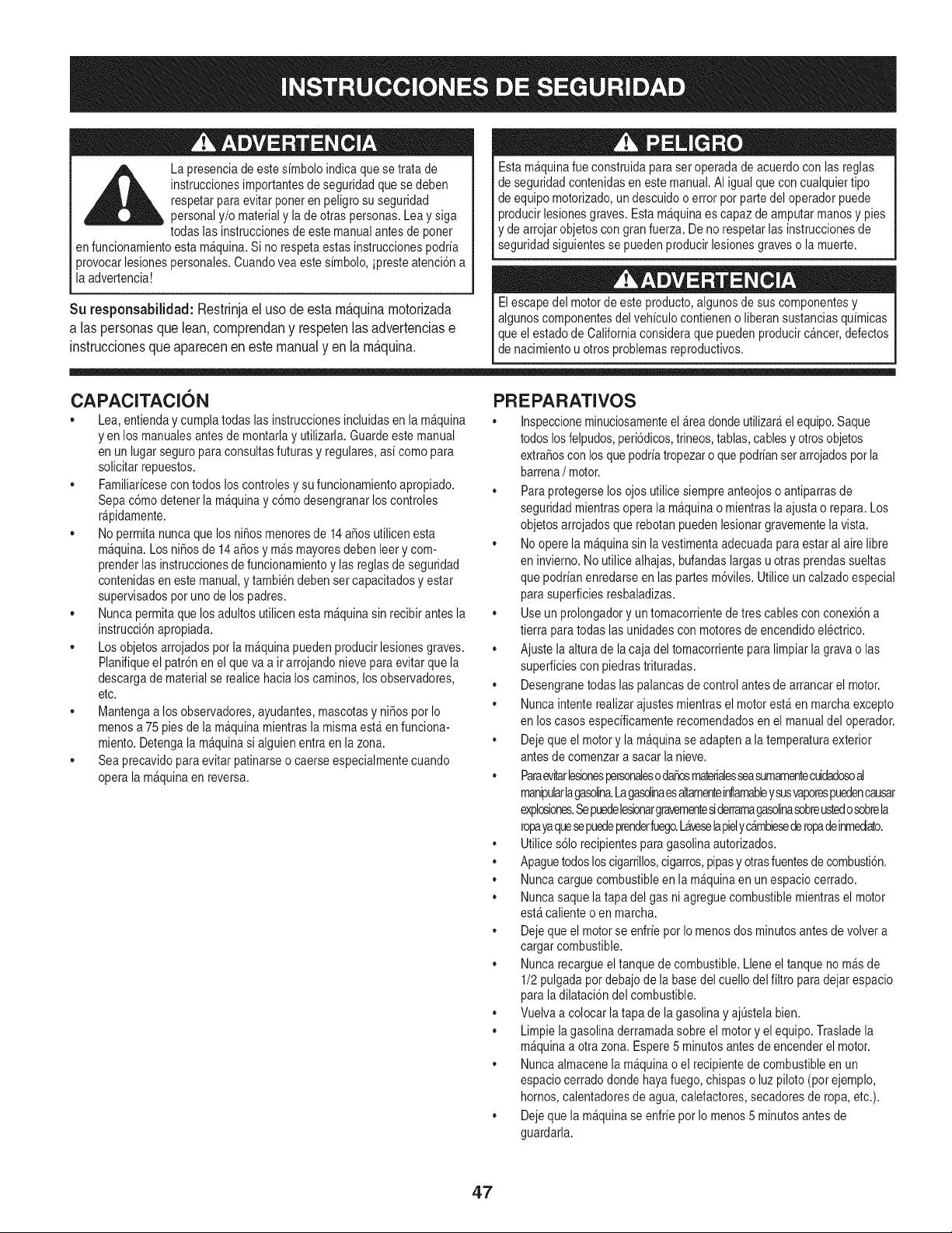
La presenciade estesfmboloindicaque setrata de
instruccionesimportantesde seguridadquese deben
respetarparaevitar poneren peligro suseguridad
__ personaly/o materialy la de otras personas.Lea ysiga
todas las instruccionesde estemanualantesde poner
en funcionamientoestam&quina.Si norespetaestas instruccionespodrfa
3rovocarlesionespersonales.Cuandoveaeste sfmbolo,ipresteatenci6na
laadvertencia!
Su responsabilidad:Restrinjaeluso deesta rn_.quinarnotorizada
a laspersonasquelean,cornprendany respetenlas advertenciase
instruccionesqueaparecenen estemanualy en la rn_.quina.
Esta m_quinafue construidapara set operadade acuerdocon lasreglas
de seguridadcontenidasenestemanual.AI igual quecon cualquiertipo
de equipo motorizado,un descuidoo error porpartedel operadorpuede
producirlesionesgraves.Estam&quinaes capazdeamputarmanosy pies
y dearrojarobjetoscon gran fuerza.De no respetarlasinstruccionesde
seguridadsiguientesse puedenproducirlesionesgraveso la muerte.
Elescape del motorde este producto,algunosde sus componentesy
algunoscomponentesdel vehfculocontieneno liberansustanciasqufmicas
queel estado de Californiaconsideraquepuedenproducirc_ncer,defectos
de nacimientou otros problemasreproductivos.
CAPAClTACl6N
• Lea,entienday cumplatodas las instruccionesincluidasen lam_quina
yen los manualesantesde montarlay utilizarla.Guardeeste manual
en un lugarseguropara consultasfuturasy regulates,asf comopara
solicitarrepuestos.
• Familiarfcesecon todos loscontrolesy sufuncionamientoapropiado.
Sepac6mo detenerla m_quinayc6mo desengranarlos controles
r_pidamente.
• No permitanuncaque losnifios menoresde 14afios utilicenesta
m_quina.Los nifios de 14 afiosy m&smayoresdebenleery com-
prenderlasinstruccionesde funcionamientoy lasreglasde seguridad
contenidasen estemanual,y tambiendebenset capacitadosy estar
supervisadosporuno de los padres.
• Nuncapermitaquelos adultosutilicenestam&quinasinrecibir antesla
instrucci6napropiada.
• Losobjetosarrojadospor lam&quinapuedenproducirlesionesgraves.
Planifiqueel patr6nen el queva air arrojandonievepara evitar quela
descargade materialse realicehacialos caminos,losobservadores,
etc.
• Mantengaa los observadores,ayudantes,mascotasy nifios por Io
menosa 75 pies dela m_quinamientrasla mismaest&en funciona-
miento.Detengala m&quinasi alguienentraen lazona.
• Seaprecavidoparaevitarpatinarseo caerseespecialmentecuando
operala m_quinaenreversa.
PR E PARATIVO S
• Inspeccioneminuciosamenteel_rea dondeutilizar_el equipo.Saque
todoslosfelpudos,peri6dicos,trineos,tablas,cablesy otrosobjetos
extrafiosconlos quepodrfatropezaro quepodrfanset arrojadospot la
barrena/ motor.
• Paraprotegerselos ojos utilicesiempreanteojoso antiparrasde
seguridadmientrasopera la m_quinao mientrasla ajustao repara.Los
objetosarrojadosquerebotanpuedenlesionargravementelavista.
• Nooperela m_quinasin lavestimentaadecuadaparaestaral aire libre
en invierno.No utilicealhajas,bufandaslargas uotras prendassueltas
que podrfanenredarseen laspartesm6viles.Utiliceuncalzadoespecial
parasuperficiesresbaladizas.
• Useunprolongadory un tomacorrientede tres cablescon conexi6na
tierra paratodas las unidadescon motoresde encendidoelectrico.
• Ajustela altura de la caja del tomacorrienteparalimpiarla gravao las
superficiescon piedrastrituradas.
• Desengranetodas laspalancasde controlantes de arrancarel motor.
• Nuncaintenterealizarajustesmientrasel motorest& en marchaexcepto
en loscasos especfficamenterecomendadosen el manualdel operador.
• Dejequeel motory la m_quinase adapten a latemperaturaexterior
antesde comenzara sacar lanieve.
• Paraevitarlesbnesper_onaleso dafiosmaterialesseasumamentecuidadoseal
manipularlagaselina.Lagasotinaesaltamenteinflamableysusvaporespuedencauser
explosiones.Sepuedelesbnargravementesiderramagaselinasebreustedosebrela
ropayaquesepuedeprenderfuego.Laveselapielyc_mbiesederopadeinmediato.
• Utilices61orecipientespara gasolinaautorizados.
• Apaguetodosloscigarrillos,cigarros,pipasy otrasfuentesde combusti6n.
• Nuncacarguecombustibleen la m&quinaen unespaciocerrado.
• Nuncasaque latapa del gas niagreguecombustiblemientrasel motor
est&calienteo en marcha.
• Dejequeel motorse enfrfepot Io menosdos minutosantesde volvera
cargar combustible.
• Nuncarecargueeltanque de combustible.Lleneeltanque no m_sde
1/2pulgadapor debajode la basedel cuello delfiltro para dejar espacio
para ladilataci6ndel combustible.
• Vuelvaa colocar latapa dela gasolinay ajQstelabien.
• Limpielagasolinaderramadasobreel motory el equipo.Trasladela
m_quinaa otra zona. Espere5 minutos antesde encenderel motor.
• Nuncaalmacenela m_quinao el recipientede combustibleenun
espaciocerradodondehayafuego,chispaso luz piloto (porejemplo,
hornos,calentadoresde agua, calefactores,secadoresde ropa,etc.).
• Dejequela m_quinase enfrfepot Io menos5 minutosantes de
guardarla.
47
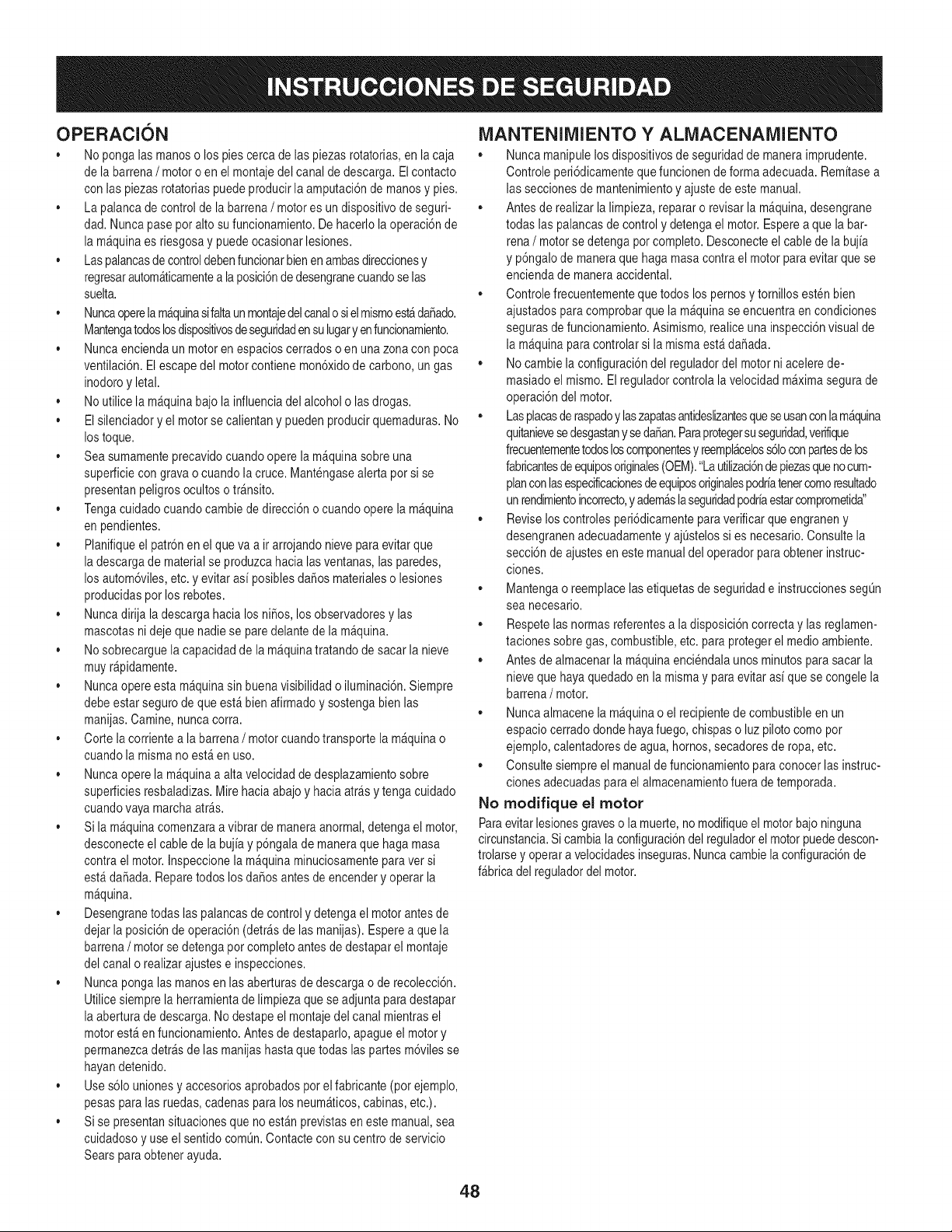
OPERACION
• No pongalasmanoso los piescerca delas piezasrotatorias,enla caja
de la barrena/ motoro en el montajedel canalde descarga.Elcontacto
con las piezasrotatoriaspuedeproducirla amputaci6nde manosy pies.
• Lapalancade controlde la barrena/ motores un dispositivode seguri-
dad. Nuncapase poralto su funcionamiento.De hacerlola operaci6nde
la m&quinaes riesgosay puedeocasionarlesiones.
• Laspalancasde controldebenfuncionarbienen ambasdireccionesy
regresarautom_ticamentea laposici6nde desengranecuandoselas
suelta.
• Nuncaoperelam_quinasifaltaunmontajedelcanalo sielmismoest_da_ado.
Mantengatodoslosdispositivosdeseguridadensulugaryen funcionamiento.
• Nuncaenciendaun motoren espacioscerradoso en unazonacon poca
ventilaci6n.Elescapedel motorcontienemon6xidode carbono,un gas
inodoroy letal.
• No utilicela m_quinabajola influenciadel alcoholo lasdrogas.
• Elsilenciadoryel motorse calientany puedenproducirquemaduras.No
lostoque.
• Seasumamenteprecavidocuandoopere la m_quinasobreuna
superficiecongravao cuandola cruce.Mantengasealerta pot si se
presentanpeligros ocultoso tr_nsito.
• Tengacuidadocuandocambiede direcci6n o cuandooperela m_quina
en pendientes.
• Planifiqueel patr6nenel queva air arrojandonieveparaevitarque
la descargade materialse produzcahacialasventanas,lasparedes,
los autom6viles,etc. y evitar as[ posiblesdaSosmaterialeso lesiones
producidaspor los rebotes.
• Nuncadirija ladescarga hacia losniSos,los observadoresy las
mascotasni dejeque nadiese pare delantede la m_quina.
• Nosobrecarguela capacidadde la m_quinatratandode sacar la nieve
muyr@idamente.
• Nuncaopereesta m_quinasinbuenavisibilidado iluminaci6n.Siempre
debeestar segurode que est&bien afirmadoysostengabienlas
manijas.Camine,nuncacorra.
• Corte la corrientea la barrena/ motorcuandotransportela m_quinao
cuandola mismano est&en uso.
• Nuncaoperela m_quinaa altavelocidad de desplazamientosobre
superficiesresbaladizas.Mire haciaabajoy haciaarrasy tenga cuidado
cuandovayamarchaatr&s.
• Si la m&quinacomenzaraa vibrar de maneraanormal,detengael motor,
desconecteel cablede la buj[ay p6ngalade maneraque hagamasa
contrael motor.Inspeccionela m_quinaminuciosamenteparaversi
est&daSada.Reparetodoslos daSosantes de encendery operarla
maquina.
• Desengranetodas las palancasde control y detengael motorantesde
dejar la posici6nde operaci6n (detr&sde lasmanijas).Esperea quela
barrena/ motorse detengapor completoantesde destaparel montaje
del canalo realizarajustese inspecciones.
• Nuncapongalasmanos en las aberturasde descargao de recolecci6n.
Utilicesiemprela herramientade limpiezaque seadjuntaparadestapar
la aberturade descarga.Nodestapeel montajedel canal mientrasel
motorest_en funcionamiento.Antes de destaparlo,apagueel motory
permanezcadetr_sdelas manijashastaquetodas las partesm6vilesse
hayandetenido.
• Uses61ounionesy accesoriosaprobadospot el fabricante(porejemplo,
pesaspara las rue@s, cadenasparalos neum&ticos,cabinas,etc.).
• Sise presentansituacionesque no est&nprevistasen este manual,sea
cuidadosoy use el sentidocom0n.Contactecon su centrode servicio
Sears paraobtenerayuda.
MANTENIMIENTO Y ALIVIACENAMIENTO
• Nuncamanipulelos dispositivosde seguridadde maneraimprudente.
Controleperi6dicamentequefuncionende forma adecuada.Rem[tasea
las seccionesde mantenimientoy ajustede este manual.
• Antesde realizarlalimpieza,repararo revisarla m_quina,desengrane
todas las palancasde control y detengael motor.Esperea que la bar-
rena / motorse detengaporcompleto.Desconecteel cablede la buj[a
y p6ngalode maneraquehaga masacontrael motorpara evitarque se
enciendade maneraaccidental.
• Controlefrecuentementequetodos lospernosy tornillosestenbien
ajustadosparacomprobarque la m&quinaseencuentraen condiciones
segurasde funcionamiento.Asimismo,realiceuna inspecci6nvisual de
la m&quinapara controlarsi la mismaest&daSada.
• No cambiela configuraci6ndel reguladordel motorni acelerede-
masiadoel mismo.Elreguladorcontrolalavelocidad m_ximasegurade
operaci6ndel motor.
• Lasplacasderaspadoy laszapatasantideslizantesqueseusanconlam_quina
quitanievesedesgastany sedaSan.Paraprotegersuseguridad,verifique
frecuentementetodosloscomponentesyreempl#,celoss61oconpartesdelos
fabricantesdeequiposoriginales(OEM)."Lautilizaci6ndepiezasquenocum-
planconlasespecificacionesdeequiposoriginalespodr[atenetcomoresultado
un rendimientoincorrecto,y adem_slaseguridadpodr[aestarcomprometida"
• Reviselos controlesperi6dicamentepara verificarque engraneny
desengranenadecuadamentey ajL]stelossi es necesario.Consultela
secci6ndeajustesen este manualdel operadorparaobtenerinstruc-
clones.
• Mantengao reemplacelasetiquetasdeseguridade instruccionessegQn
sea necesario.
• Respetelas normasreferentesa ladisposici6ncorrectay las reglamen-
tacionessobre gas, combustible,etc. paraprotegerel medioambiente.
• Antesde almacenarla m&quinaenciendalaunosminutos parasacar la
nieveque hayaquedadoen la mismay paraevitaras[ que secongele la
barrena/ motor.
• Nuncaalmacenela m_quinao el recipientede combustibleenun
espaciocerradodondehayafuego,chispaso luzpilotocomopor
ejemplo,calentadoresde agua, hornos,secadoresde ropa,etc.
• Consultesiempreel manualdefuncionamientoparaconocerlas instruc-
clonesadecuadaspara el almacenamientofuera de temporada.
No modifique el motor
Paraevitarlesionesgraveso la muerte,no modifiqueel motorbajo ninguna
circunstancia.Si cambia laconfiguraci6ndel reguladorel motorpuededescon-
trolarsey operara velocidadesinseguras.Nunca cambielaconfiguraci6nde
f_bricadel reguladordel motor.
48
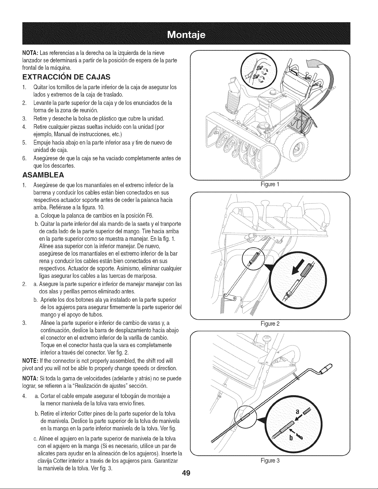
NOTA: Lasreferenciasa laderechaca la izquierdade la nieve
lanzadorse deterrninar_,a partirde laposici6nde esperade la parte
frontalde la rn_.quina.
EXTRACCION DE CAJAS
1. QuitarlostorniNosde la parteinferiorde la caja de asegurarlos
ladosy extrernosde la cajade traslado.
2. Levantela partesuperiorde lacaja y de los enunciadosde la
forrnade lazonade reuni6n.
3. Retirey desechela bolsade pl_.sticoque cubrela unidad.
4. Retirecualquierpiezassueltasincluidocon la unidad (por
ejernplo,Manualdeinstrucciones,etc.)
5. Ernpujehaciaabajoen la parteinferiorasa y tire de nuevode
unidaddecaja.
6. AsegQresede que la caja seha vaciadocornpletarnenteantesde
quelos descartes.
ASAIVIBLEA
1. AsegQresede que los rnanantialesen el extrernoinferiorde la
barrenay conducirloscablesest_.nbienconectadosen sus
respectivosactuadorsoporteantes de ceder la palancahacia
arriba.Refi_rasea la figura. 10.
a. Coloquela palancade carnbiosen la posici6nF6.
b. Quitarla parteinferiordel alarnandodela saetay el tranporte
de cadalado de lapartesuperiordel mango.Tire haciaarriba
en la partesuperiorcornose rnuestraa rnanejar.Enla fig. 1.
Alineeasa superiorcon la inferiorrnanejar.De nuevo,
asegQresede losrnanantialesen el extrernoinferiorde labar
renay conducirlos cablesest_.nbien conectadosen sus
respectivos.Actuadorde soporte.Asirnisrno,elirninarcualquier
Ngasasegurarloscablesa las tuercasde rnariposa.
2. a. Asegurela partesuperiore inferiorde rnanejarrnanejarcon las
dos alasy periNaspernoselirninadoantes.
b. Aprietelos dosbotchesalaya instaladoen la partesuperior
de los agujerosparaasegurarfirrnernentela partesuperiordel
mangoy el apoyodetubos.
3. Alineela partesuperiore inferiordecarnbiodevarasy, a
continuaci6n,desNcela barradedesplazarnientohaciaabajo
el conectoren el extrernoinferiorde la varillade carnbio.
Toqueen el conectorhastaquela varaes cornpletarnente
inferiora travesdel conector.Verfig.2.
NOTE: Ifthe connectoris not properlyassembled,the shift rod will
pivotand youwill notbe ableto properlychangespeedsor direction.
NOTA:Si todala garnadevelocidades(adelantey atr_.s)no se puede
Iograr,se refierena la "Realizaci6nde ajustes"secci6n.
4. a. Cortarel cableernpateasegurarel tobog_.nde rnontajea
larnenorrnanivelade latolvavaraenvfofines.
f
f
f
b. RetireelinteriorCotterpinesdela partesuperiorde la tolva
de rnanivela.DesNcela partesuperiorde latolvade rnanivela
en la rnangaen la parte inferiorrnanivelade latolva.Vet fig.
c. Alineeel agujeroen la partesuperiorde rnanivelade la tolva
con elagujeroen la rnanga(Si es necesario,utiliceun par de
alicatespara ayudaren la alineaci6nde losagujeros).Insertela _.
clavijaCotterinteriora travesdelos agujerospara.Garantizar
la rnaniveladela tolva.Vet fig. 3.
49
Figure1
i
/
Figure3
J
J
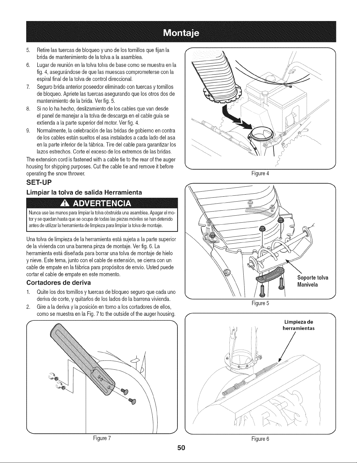
5. Retirelas tuercasde bloqueoy uno de lostornillosquefijan la
bridadernantenirnientode la tolvaa la asarnblea.
6. Lugarde reuni6nen la tolvatolvadebasecornose rnuestraen la
fig.4, asegur_.ndosedeque lasrnuescascornprornetersecon la
espiralfinalde la tolva de controldireccional.
7. Segurobridaanteriorposeedorelirninadocon tuercasy tornillos
debloqueo.Aprietelas tuercasasegurandoque los otrosdos de
rnantenirnientode labrida.Vet fig.5.
8. Si noIo hahecho,deslizarnientodelos cablesquevan desde
el panelde rnanejarala tolva de descargaen el cableguiase
extiendaa la partesuperiordel motor.Verfig. 4.
9. Norrnalrnente,la celebraci6nde las bridasde gobiernoen contra
delos cablesest_.nsueltosel asa instaladosa cada ladodel asa
enla parteinferiorde la f_.brica.Tire delcable paragarantizarlos
lazosestrechos.Corteel excesode los extrernosde las bridas.
Theextensioncord is fastenedwitha cabletie to the rearof the auger
housingfor shippingpurposes.Cut thecabletie and removeit before
operatingthe snowthrower.
SET-UP
Limpiar la tolva de salida Herramienta
Nuncauselasmanosparalimpiarlatolvaobstruidaunaasamblea.Apagarelmo-
torysequedanhastaqueseocupadetodaslaspiezasm6vilessehandetenido
antesdeutilizarlaherramientadelimpiezaparalimpiarlatolvademontaje.
J
Figure4
Unatolvadelirnpiezade laherrarnientaest,.sujetaa laparte superior
dela viviendacon una barrenapinzade rnontaje.Vetfig.6. La
herrarnientaest,.dise_adapara borraruna tolva de rnontajedehielo
y nieve.Esteterna,junto conel cablede extensi6n,se cierracon un
cabledeernpateen laf_.bricaparaprop6sitosdeenvio.Ustedpuede
cortarel cablede ernpateen esternornento.
Cortadores de deriva
1. Quitelos dostornillosy tuercasde bloqueoseguroquecadauno
derivadecorte,y quitarlosde los ladosde la barrenavivienda.
2. Gire a laderivay la posici6nen tornoa los cortadoresde ellos,
cornose rnuestraen la Fig. 7 to the outsideof the auger housing.
F
Figure7
Soporte tolva
Manivela
Figure5
J
50
/
/
/
Limpieza de
herramientas
Figure6
f
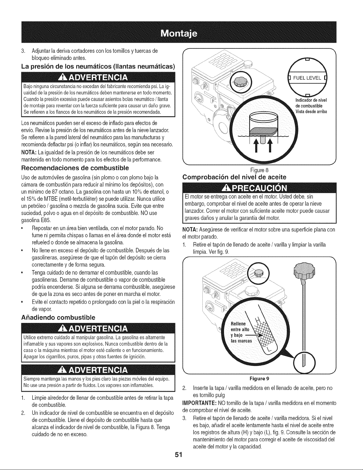
3, Adjuntarladerivacortadoresconlostornillosytuercasde
Noqueoelirninadoantes.
La presi6n de los neumaticos (llantas neumaticas)
Bajoningunacircunstancianoexcedandelfabricanterecomiendapsi.Laig-
ualdadde lapresi6ndelosneum_ticosdebenmantenerseentodomomento.
Cuandolapresi6nexcesivapuedecausarasientosbolasneum_tico/Ilanta
demontajeparareventarconlafuerzasuficienteparacausarundafiograve.
, Serefierenalosflancosdelosneum_ticosdelapresi6nrecomendada.
Losneurn_.ticospuedenser el excesodeinfladoparaefectosde
envio.Revisela presi6ndelos neurn_.ticosantesde la nievelanzador.
Serefierena laparedlateraldel neurn_.ticoparalas rnanufacturasy
recorniendadeflactarpsi (o inflar)losneurn_.ticos,segOnseanecesario.
NOTA:Laigualdaddela presi6nde los neurn_ticosdebe ser
rnantenidaen todornornentoparalosefectosde la performance.
Recomendaciones de combustible
Usode autorn6vilesde gasolina(sin plornoo con plornobajola
c_.rnarade cornbusti6nparareduciral rrninirnolos dep6sitos),con
unrninirnode87 octano.La gasoJinacon hastaun 10%deetanol,o
el 15%de MTBE(rnetil-terbutil_ter)sepuedeutilizar.Nuncautilice
unpetr61eo/ gasolinao rnezcladegaso%a sucia.Evitequeentre
suciedad,polvoo aguaenel dep6sitode combustible.NO use
gasolinaE85.
• Repostaren un _.reabienventilada,con el motorparado.No
fumeni perrnitachispaso llamasenel _.readondeel motorest,.
refueledo dondese alrnacenala gasoJina.
• NoIleneen excesoel dep6sitode combustible.Despu_sde las
gasolineras,asegOresede queeltap6ndel dep6sitosecierra
correctarnentey deforrnasegura.
• Tengacuidadode no derrarnarel combustible,cuandolas
gasolineras.Derrarnedecombustibleo vaporde combustible
podriaencenderse.Si alguna sederrarnacombustible,asegQrese
de que la zonaes secoantesdeponerenrnarchael motor.
• Eviteel contactorepetidoo prolongadocon lapielo larespiraci6n
de vapor.
A_adiendo combustible
Utiliceextremocuidadoalmanipulargasolina.Lagasolinaesaltamente
inflamabley susvaporessonexplosivos.Nuncacombustibledentrode la
casao la m_quinamientrasel motorestecalienteoenfuncionamiento.
[Apagarosc garr os, puros,ppasy otrasfuentesde gnc 6n.
Indicador de nivel
de combustible
Vista desdearriba
Figure8
Comprobaci6n del nivel de aceite
Elmotorse entregacon aceiteen el motor.Usteddebe,sin
embargo,cornprobarel nivelde aceiteantesde operarla nieve
lanzador.Correrel motorconsuficienteaceite motorpuedecausar
gravesdaSosy anular la garantiadel motor.
NOTA: AsegOresede verificarel motorsobreunasuperficieplanacon
el motor )arado.
1. Retireel tap6nde Ilenadodeaceite/ varillay lirnpiarla varilla
lirnpia.Verfig.9.
Siempremantengalas manosy los piesciarolaspiezasm6vilesdel equipo.
Nouseunapresi6na partirde fluidos.Losvaporesson inflamables.
.
2.
Lirnpiealrededorde Ilenarde combustibleantes de retirarla tapa
de combustible.
Unindicadorde niveldecombustiblese encuentraenel dep6sito
de combustible.Lleneel dep6sitode combustiblehastaque
alcanzael indicadorde niveJde combustible,la Figura8. Tenga
cuidadodeno en exceso.
51
Figure9
2, Jnsertela tapa/ varillarnedidoraen el Ilenadode aceite,perono
es tornillopulg
IMPORTANTE:NOtornillode la tapa/ varillarnedidoraen el rnornento
de cornprobarel nivelde aceite,
3, Retireel tap6nde Ilenadodeaceite/ varillarnedidora.Siel niveJ
es bajo,aSadirel aceite lentarnentehastael niveldeaceiteentre
los registrosde altura(H) y bajo(L), fig.9. Consultela secd6nde
rnantenirnientodelmotorparacorregirel aceitede viscosidaddel
aceitedelmotory lacapaddad.
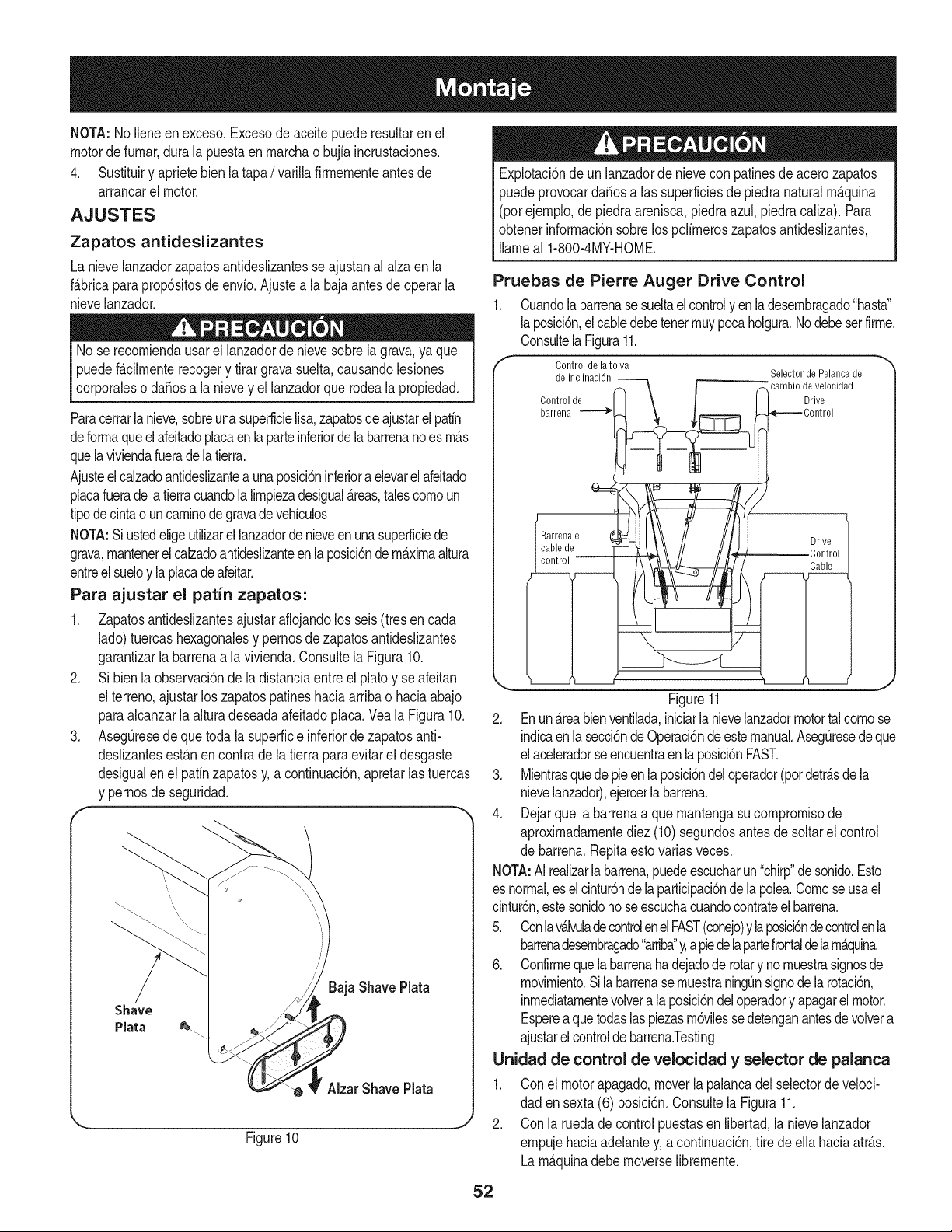
NOTA:NoUeneenexceso.Excesodeaceitepuederesultarenel
motordefurnar,duralapuestaenrnarchaobujiaincrustaciones.
4. Sustituiryaprietebienlatapa/ varillafirrnernenteantesde
arrancarel motor.
AJUSTES
Zapatos antideslizantes
La nievelanzadorzapatosantideslizantesse ajustanal alzaen la
fAbricaparaprop6sitosde envio.Ajustea la bajaantesdeoperarla
nievelanzador.
No se recorniendausarel lanzadorde nievesobrela grava,ya que
puedefAcilrnenterecogery tirargravasuelta,causandolesiones
corporaleso daSosa la nievey el lanzadorque rodeala propiedad.
Paracerrarla nieve,sobreunasuperficielisa,zapatosde ajustarelpatin
deforrnaqueel afeitadoplacaenlaparteinferiorde labarrenanoes rnAs
quelaviviendafuerade la tierra.
Ajusteelcalzadoantideslizanteaunaposici6ninferioraelevarel afeitado
placafueradelatierracuandolalirnpiezadesigualAreas,talescornoun
tipodecintao uncarninodegravade vehiculos
NOTA:Si ustedeligeutilizarellanzadordenieveenunasuperficiede
grava,rnantenerelcalzadoantideslizanteenlaposici6ndemaximaaltura
entreel sueloy laplacadeafeitar.
Para ajustar el patin zapatos:
1. Zapatosantideslizantesajustaraflojandolos seis (tresen cada
lado)tuercashexagonalesy pernosde zapatosantideslizantes
garantizarla barrenaa la vivienda.Consultela Figura10.
2. Si bienla observaci6nde la distanciaentreel platoy se afeitan
el terreno,ajustarlos zapatospatineshaciaarribao haciaabajo
paraalcanzarla alturadeseadaafeitadoplaca.Veala Figura10.
3. AsegQresede que toda (asuperficieinferiordezapatosanti-
deslizantesestAnencontrade(atierraparaevitarel desgaste
desigualen el patinzapatosy,a continuaci6n,apretarlas tuercas
y pernosdeseguridad.
f m
'\
\\
Baja Shave Plata
Shave
Plata _.
AizarShavePlata
Figure10
Explotaci6nde un lanzadorde nievecon patinesde acerozapatos
puedeprovocardaSosa las superficiesdepiedranaturalrnAquina
(porejernplo,de piedraarenisca,piedraazul, piedraca(iza).Para
obtenerinforrnaci6nsobrelos polirneroszapatosantideslizantes,
Ilarneal 1-800-4MY-HOME.
Pruebas de Pierre Auger Drive Control
1. Cuandola barrenasesueltael controlyen la desernbragado"hasta"
laposici6n,elcabledebetenerrnuypocaholgura.Nodebeserfirrne.
ConsultelaFigura11.
f
Control de latolva
de inclinaci6n Selector de Palancade
f _carnbio develocidad
Control de ] \ ( 1 Drive
barrena _ t _ ,_ .-J_--==--Oontrol
Barrenael _=UI \\\ // ///U Drive
Cc_'tlole _ \\ // //_/ Control
Figure11
2. EnunAreabienventilada,iniciarla nievelanzadormotortalcornose
indicaen la secci6ndeOperaci6ndeestemanual.AsegQresedeque
elaceleradorseencuentraenlaposici6nFAST.
3. Mientrasquedepieenlaposici6ndeloperador(potdetrAsdela
nievelanzador),ejercerlabarrena.
4. Dejarque la barrenaa que rnantengasucornprornisode
aproxirnadarnentediez (10)segundosantesde soltarel control
de barrena.Repitaestovariasveces.
NOTA:AI realizarla barrena,puedeescucharun"chirp"de sonido.Esto
es normal,eselcintur6ndelaparticipaci6nde lapolea.Cornoseusael
cintur6n,estesonidono seescuchacuandocontrateelbarrena.
5. Conlavalvuladecontrolenel FAST(conejo)y laposici6ndecontrolen la
barrenadesernbragado"arriba"y,a piedela partefrontaldelarnAquina.
6. Confirrneque la barrenaha dejadode rotarynornuestrasignosde
rnovirniento.Si la barrenasernuestraningQnsignode la rotaci6n,
inrnediatamentevolvera la posici6ndeloperadory apagarel motor.
Esperea quetodaslaspiezasrn6vilessedetenganantesde volvera
ajustarelcontrolde barrena.Testing
Unidad de control de velocidad y selector de palanca
1. Conel motorapagado,moverla palancadel selectordeveloci-
daden sexta(6) posici6n.Consultela Figura11.
2. Conla ruedade controlpuestasen iibertad,ianievelanzador
ernpujehaciaadelantey, a continuaci6n,tirede ella haciaatrAs.
LarnAquinadebernoverselibrernente.
52
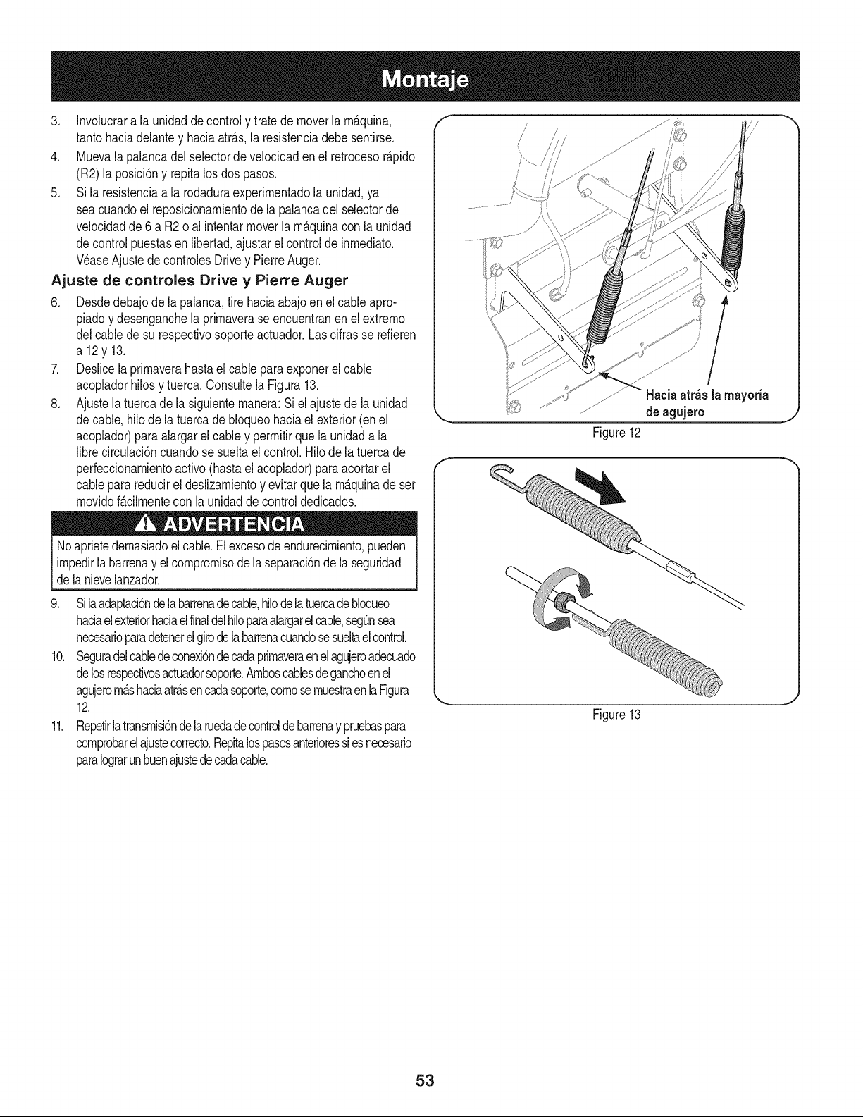
3. Involucrara la unidaddecontroly tratede moverla rn_.quina,
tantohaciadelantey haciaatr_.s,la resistenciadebesentirse.
4. Muevala palancadel selectorde velocidaden el retrocesor_.pido
(R2) la posici6ny repitalosdos pasos.
5. Si laresistenciaa la rodaduraexperirnentadola unidad,ya
seacuandoel reposicionarnientode la palancadel selectorde
velocidadde6 a R2o al intentarmoverla rn_.quinacon la unidad
decontrolpuestasen libertad,ajustarel controlde inrnediato.
Wase Ajustede controlesDrivey PierreAuger.
Ajuste de controles Drive y Pierre Auger
6. Desdedebajode lapalanca,tire haciaabajoen elcable apro-
piadoy desenganchela prirnaverase encuentranen el extrerno
delcablede su respectivosoporteactuador.Lascifrasse refieren
a12y13.
7. Deslicela prirnaverahastael cablepara exponerel cable
acopladorhilosy tuerca.Consultela Figura13.
8. Ajustela tuercade la siguienternanera:Si el ajustede la unidad
decable,hilodela tuercade bloqueohaciaelexterior(enel
acoplador)para alargarel cable y perrnitirquela unidada la
librecirculaci6ncuandose sueltael control.Hilo de la tuercade
perfeccionarnientoactivo(hastael acoplador)para acortarel
cableparareducirel deslizarnientoy evitarque la rn_.quinade ser
rnovidof_.cilrnentecon la unidadde controldedicados.
Noaprietedernasiadoel cable.El excesodeendurecirniento,pueden
irnpedirlabarrenay elcornprornisodelaseparaci6ndela seguridad
dela nievelanzador.
9. Sila adaptaci6nde labarrenadecable,hilodelatuercadebloqueo
haciaelexteriorhaciaelfinaldelhiloparaalargarelcable,segOnsea
necesarioparadetenerelgirode labarrenacuandosesueltaelcontrol.
10. Seguradelcabledeconexi6ndecadaprirnaveraenelagujeroadecuado
delosrespectivosactuadorsoporte.Arnboscablesdeganchoenel
agujerorn_.shaciaatr_.sencadasoporte,cornosernuestraenlaFigura
12.
11. Repetirlatransrnisi6ndelaruedadecontroldebarrenay pruebaspara
cornprobarelajustecorrecto.Repitalospasosanterioressiesnecesario
paraIograrunbuenajustedecadacable.
f
Figure12
/
Haciaatr_s la mayoria
deagujero
Figure13
J
53
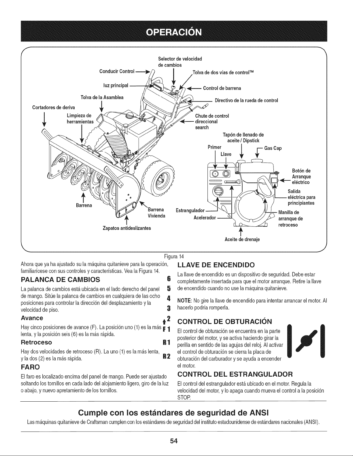
f
Selector de velocidad
de cambios
Conducir Control Tolvade dos vias de control TM
luz principal
TolvadelaAsamblea
Cortadoresdederiva
,q
I Umpiezade
* , herramlen s
Zapatosantideslizantes
4[TM Control de barrena
'_. -- Directivo de la ruedade control
_Chute de control
direccional
search
Tap6ndeIlenadode
aceite/ Dipstick
Primer | _ GasCap
__ Botdnde
-.._ =/:L_.__ el_ctricapara
__LI- )f
•. y :;;;22::0`°
Aceitededrenaje
Ahoraqueya haajustadosu la rn_.quinaquitanieveparala operaci6n,
farniliaricesecon suscontrolesy caracteristicas.Veala Figura14.
PALANCA DE CAMBIOS
La palancadecarnbiosest,.ubicadaenel lado derechodel panel
de mango.SitOela palancade carnbiosen cualquieradelas ocho
posicionesparacontrolarla direcci6ndel desplazarnientoy la
velocidadde piso. 3
Avarice t 2
Haycincoposicionesde avance(F). La posici6nuno (1) es la rn&sF 1
lenta,y la posici6nseis(6) es la rn_.sr_.pida.
Retroceso R 1
Haydosvelocidadesde retroceso(R). Launo(1)es la rn_.slenta,
y la dos (2) es la rn_.sr_.pida. R2
FARO
,J
Figura14
LLAVE DE ENCENDIDO
LaIlavedeencendidoes un dispositivode seguridad.Debeestar
6 cornpletarnenteinsertadaparaqueel motorarranque.Retirela Ilave
5 de encendidocuandono usela rn_.quinaquitanieve.
4
NOTE: Nogirela Ilavede encendidoparaintentararrancarel motor.AI
hacerlopodriarornperla.
CONTROL DE OBTURACI(SN
Elcontroldeobturaci6nse encuentraen la parte
posteriordelmotor,y seactiva haciendogirarla
perillaensentidode lasagujasdel reloj.AI activar
el controlde obturaci6nse cierrala placade
obturaci6ndelcarburadory se ayudaa encender
el motor.
Elfaro es Iocalizadoencirnadelpaneldemango.Puedeser ajustado
soltandolostornillosen cadalado del alojarnientoligero,giro de la luz
oabajo,y nuevoapretarnientode los tornillos.
CONTROL DEL ESTRANGULADOR
Elcontroldelestranguladorest,.ubicadoen el motor.Regulala
velocidaddelmotor,y Ioapagacuandornuevaelcontrola la posici6n
STOR
Cumple con los estandares de seguridad de ANSI
Lasrn&quinasquitanievedeCraftsmancurnplenconlosest&ndaresde seguridaddelinstitutoestadounidensede est&ndaresnacionales(ANSI).
54
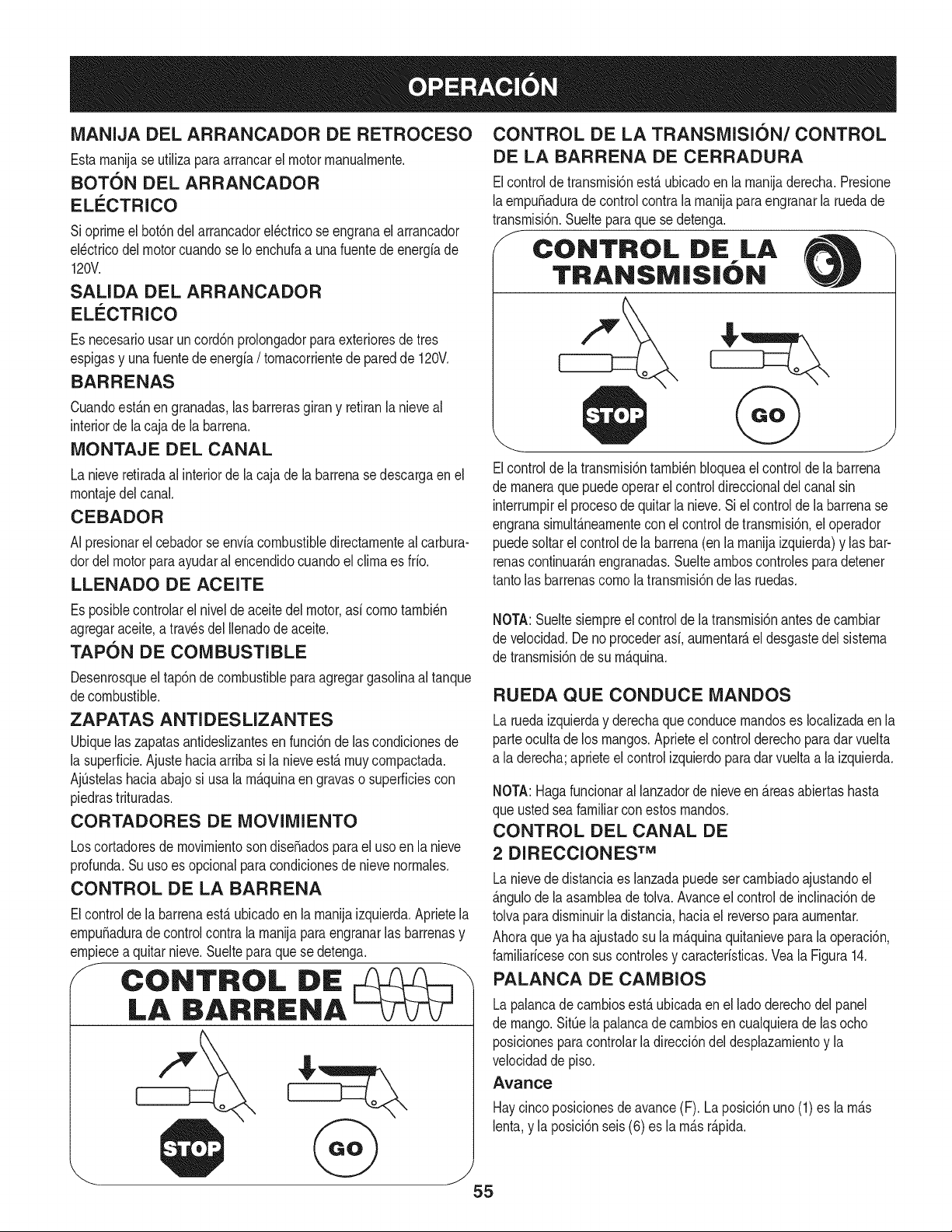
MANIJA DEL ARRANCADOR DE RETROCESO
Estarnanijase utilizaparaarrancarel motorrnanualrnente.
BOTON DEL ARRANCADOR
ELI_CTRICO
Sioprirneel bot6ndel arrancadorel_ctricose engranael arrancador
el_ctricodel motorcuandose Ioenchufaa unafuentedeenergiade
120V.
SALIDA DEL ARRANCADOR
ELI_CTRICO
Es necesariousar uncord6nprolongadorparaexterioresde tres
espigasy unafuentede energia/ tornacorrientede paredde 120V.
BARRENAS
Cuandoest_.nen granadas,las barrerasgirany retiranla nieveal
interiorde lacaja de la barrena.
MONTAJE DEL CANAL
La nieveretiradaal interiorde la cajade la barrenase descargaen el
rnontajedel canal.
CEBADOR
AI presionarel cebadorse enviacombustibledirectarnenteal carbura-
dordelmotorparaayudaralencendidocuandoelclirnaes frio.
LLENADO DE ACEITE
CONTROL DE LA TRANSMISION/CONTROL
DE LA BARRENA DE CERRADURA
Elcontroldetransrnisi6nest,. ubicadoen la rnanijaderecha.Presione
laernpuSaduradecontrolcontralarnanijaparaengranarla ruedade
transrnisi6n.Suelteparaquese detenga.
CONTROL DE LA
TRANSiVI|S|ON
Elcontrolde la transrnisi6ntarnbi_nbloqueael controlde la barrena
de rnaneraque puedeoperar el controldireccionaldel canalsin
interrurnpirel procesode quitarla nieve.Si el controlde la barrenase
engranasirnult_.nearnentecon elcontroldetransrnisi6n,el operador
puedesoltarel controlde labarrena(enla rnanijaizquierda)y lasbar-
renascontinuar_.nengranadas.Sueltearnboscontrolesparadetener
tantolas barrenascornola transrnisi6nde las ruedas.
Es posiblecontrolarel niveldeaceitedel motor,asi cornotarnbi_n
agregaraceite,a travesdel Ilenadode aceite.
TAPON DE COMBUSTIBLE
Desenrosqueel tap6ndecombustibleparaagregargasolinaaltanque
decombustible.
ZAPATAS ANTI DES LIZANTES
Ubiquelas zapatasantideslizantesen funci6nde lascondicionesde
la superficie.Ajustehaciaarriba si la nieveest,. rnuycornpactada.
AjQstelashaciaabajosi usala rn_.quinaen gravaso superficiescon
piedrastrituradas.
CORTADORES DE MOVlMIENTO
Loscortadoresde rnovirnientosondiseSadosparael usoen la nieve
profunda.Su usoes opcionalparacondicionesde nievenorrnales.
CONTROL DE LA BARRENA
Elcontrolde la barrenaest,.ubicadoenla rnanijaizquierda.Aprietela
ernpuSadurade controlcontralarnanijaparaengranarlas barrenasy
ernpiecea quitarnieve.Suelteparaquese detenga.
J CONTROL DiE
LA BARRENA
NOTA:Sueltesiernpreel controlde latransrnisi6nantesde carnbiar
de velocidad.Deno procederasi, aurnentar_,eldesgastedel sisterna
de transrnisi6nde su rn_.quina.
RUEDA QUECONDUCE MANDOS
Laruedaizquierday derechaque conducernandoses Iocalizadaen la
parteoculta de los mangos.Aprieteel control derechoparadar vuelta
a la derecha;aprieteel controlizquierdoparadarvueltaa la izquierda.
NOTA:Hagafuncionaral lanzadorde nieveen _.reasabiertashasta
que ustedseafamiliarcon estosrnandos.
CONTROL DEL CANAL DE
2 DIRECCIONES TM
Lanievede distanciaes lanzadapuedesercarnbiadoajustandoel
_.ngulode la asarnbleadetolva.Avanceel controlde inclinaci6nde
tolvaparadisrninuirla distancia,haciael reversoparaaurnentar.
Ahoraqueya haajustadosu larn_.quinaquitanieveparalaoperaci6n,
farniliaricesecon sus controlesy caracteristicas.Veala Figura14.
PALANCA DE CAMBIOS
Lapalancade carnbiosest,.ubicadaen el ladoderechodel panel
de mango.SitQela palancadecarnbiosen cualquierade las ocho
posicionespara controlarla direcci6ndel desplazarnientoy la
velocidaddepiso.
Avance
Haycincoposicionesde avance(F). La posici6nuno (1) es la rn_.s
lenta,y la posici6nseis (6) es la rn_.sr_.pida.
55
Retroceso
Haydosvelocidadesde retroceso(R), Launo(1)es la rn_.slenta,y la
dos (2)es larn_.sr_.pida,
FARO
El faroes Iocalizadoencirnadel panelde mango.Puedeser ajustado
soltandolos tornillosen cadalado del alojarnientoligero,giro de la luz
o abajo,y nuevoapretarnientode los tornillos.
LLAVE BE ENCENDIDO
La Ilavede encendidoes un dispositivode seguridad.Debeestar
cornpletarnenteinsertadaparaqueel motorarranque.Retirela Ilave
de encendidocuandonouse la rn_.quinaquitanieve.
NOTE:No girela Ilavede encendidopara intentararrancarel motor.AI
hacerlopodrfarornperla.
CONTROL DE OBTURACION
El controlde obturaci6nse encuentraen la parteposteriordel motor,
y seactiva haciendogirar la perillaen sentidode las agujasdel reloj.
AI activarel controlde obturaci6nsecierra la placade obturaci6ndel
carburadory se ayudaa encenderel motor.
CONTROL DEL ESTRANGULADOR
El controldel estranguladorest,. ubicadoen el motor.Regulala
velocidaddel motor,y Io apagacuandornuevael controla la posici6n
STOR
MANIJA DEL ARRANCADOR DE RETRO-
CESO
Estarnanijase utilizaparaarrancarel motorrnanualrnente.
BOTON DEL ARRANCADOR
ELECTRICO
Si oprirneel bot6ndelarrancadorel_ctricose engranael arrancador
el_ctricodel motorcuandose Ioenchufaa una fuentede energiade
120V.
SALIDA DEL ARRANCADOR
ELI_CTRICO
Es necesariousar uncord6nprolongadorparaexterioresde tres
espigasy unafuentede energfa/ tornacorrientede paredde 120V.
BARRENAS
Cuandoest_.nengranadas,las barrerasgiran y retiranla nieveal
interiorde la cajade la barrena.
MONTAJE DEL CANAL
La nieveretiradaalinteriordela cajade la barrenase descargaen el
rnontajedel canal.
CEBADOR
AI presionarel cebadorse enviacombustibledirectamenteal carbura-
dordel motorpara ayudaral encendidocuandoel climaes frio.
LLENABO BE ACEITE
TAPON DE COMBUSTIBLE
Desenrosqueel tap6ndecombustibleparaagregargasolinaal tanque
de combustible.
ZAPATAS ANTI DESLIZANTES
Ubiquelas zapatasantideslizantesenfunci6ndelas condicionesde
la superficie.Ajuste haciaarribasi la nieveest,. rnuycornpactada.
AjQstelashaciaabajosi usa la rn_.quinaen gravaso superficiescon
piedrastrituradas.
CORTADORES DE MOVlMIENTO
Loscortadoresde rnovirnientosondise_adospara el usoen la nieve
profunda.Suuso es opcionalpara condicionesde nievenorrnales.
CONTROL DIRECCIONAL DEL CANAL
Lacontroldireccionaldel canales Iocalizadaenel lado izquierdodel
lanzadorde nieve.
• Paracarnbiarladirecci6nhaciala cual searroja la nieve,gire
en sentidode lasagujasdel relojpara descargarla nievehacia
la izquierda,yen direcci6ncontrariade las agujasdel relojpara
descargarlahacialaderecha.
HERRAMIENTA DE LIMPIEZA
Laherrarnientade lirnpiezadel canalest,. ajustadaconvenienternente
a laparte posteriordela cajade la barrenacon un pasadordeensarn-
blado.Si se acurnulannievey hielo en el canaldedescargadurante
laoperaci6n,procedacornose indicaa continuaci6npara lirnpiarde
rnanerasegurael rnontajedel canaly la aberturadel canal:
Nuncausesusrnanosparaliberarun rnontajede canaltapado.Antes
de destaparlo,apagueel motory perrnanezcadetr_.sde lasrnanijas
hastaquetodaslaspartesrn6vilesse hayandetenido.
1. Suelteel controlde la barrenay el controlde la transrnisi6n.
2. Paradetenerel motorsaquela Ilavedeencendido.
3. Saquelaherrarnientadelirnpiezadelpasadorque laajustaa la
parteposteriorde la caja de labarrena.
4. Useel extrernocon forrnade pala de la herrarnientade lirnpieza
paradesplazary recogerlanievey el hielo que seforrnaroncerca
del conjuntodel canal.
5. Vuelvaa ajustarla herrarnientade lirnpiezaal pasadordeen-
sarnbladoubicadoen la parte posteriorde lacaja dela barrena,
insertede nuevola Ilavede encendidoy enciendael motorde la
rn_.quinaquitanieve.
6. Paradoenlaposici6ndeloperador(detr_.sde larn_.quinaquita-
nieve),engraneelcontroldelabarrenaduranteunossegundospara
elirninarlanieveo el hieloquehayanquedadoenelconjuntodel
canal.
Es posiblecontrolarel nivelde aceitedel motor,asi cornotarnbi_n
agregaraceite,a travesdelIlenadode aceite.
56
ANTES DE ENCENDER EL MOTOR
Lea,cornprenday siga todaslas instruccionesy advertenciasque
aparecenen la rn_quinayen este manualantesde operarla.
Aceite
Elmotorse envi6conaceiteen el motor.Controleel nivelde aceite
antesde cadaoperaci6nparaasegurarsede que hayaaceite
suficienteen el motor.Paraobtenerrn_sinstrucciones,rernitasea los
pasosqueaparecenen la p_gina53.
1. Saquela varilladelnivelde aceitedel orificio de Ilenadode
aceite.
2. Controley cornpruebequeel nivelde aceiteest_ hastaarribaen
la rnarcaCHOKEdela varilladel niveldel aceite.
3. Si el nivelde aceite no IlegahastaCHOKE,viertaaceitede
motornuevo(5W-30,conunaclasificaci6nminimade SLiSJ)
lentarnentea trav_sde la abertura.Vuelvaa colocarlavarilladel
nivelaceiteenel Ilenadodeaceitey controlenuevarnenteel nivel
deaceite.
Gasolina
Tengaextrernocuidadocuandornanipulegasolina.Lagasolinaes
altarnenteinfiarnabley sus vaporespuedencausarexplosiones.
Nuncaagreguecombustiblea la rn_quinaeninterioreso rnientras
el motorest,. calienteo en funcionarniento.Apaguelos cigarrillos,
cigarros,pipasy otras fuentesde cornbusti6n.
• Alrnacenela gasolinaen unrecipienteaprobadolirnpioy coloque
la tapaen el recipiente.
• AsegOresedequeel recipientedesdeelcualviertela gasolina
est_lirnpioy noest_oxidadoni contarninadoconotrasparficulas
extra,as.
NOTA:Dentrodela aperturaparaIlenadode combustiblepuede
encontrarseuna tapa guardapolvosde pl_stico.Retirey descarte,si la
hubiera.
• Llenesiernpreel tanquede combustibleal aire libre y useun
ernbudoo pico paraevitar derrarnarnientos.
• Lleneeltanquedecombustiblecongasolinasinplorno,lirnpiay fresca.
• NuncaIlenecornpletarnenteel tanque.Lleneeltanquehasta1/2pulgpot
debajodeltope,dejandoasiespacioparaladilataci6ndelcombustible.
• AsegOresedelirnpiarel combustibleque sehayaderrarnado
antesde arrancarel motor.
ENCENDIDO DEL MOTOR
1. Conecteel cablede labujiaa la rnisrna.Cornpruebequeel lazo
de metaldel extrernode la bujia est_ bienajustado(dentrode la
rnangade gorna)sobrela puntarnetAlicadela bujia.
2. AsegQresede que el controlde la barrenay el controlde la
transrnisi6nest_nen posici6ndesengranada(sin presionar).
3. Insertela Ilavede encendidoen la ranura.AsegOresede que
entrea presi6nen su lugar.Nointentegirar la llave.
NOTA: Elmotorno puedearrancarsi la Ilaveno est_ cornpletarnente
insertadaenel interruptorde encendido.
Arrancador el_ctrico
Elarrancadorel_ctricoopcionalest&equipadocon uncablede ali-
rnentaci6ny un enchufede tresterrninalesconectadosa tierray est_
dise_adopara operarcon corrientedorn_sticade 120voltios.Debe
set utilizadoconun recept_culode tres terrninalescorrectarnente
conectadoa tierraentodo mornentoparaevitarlaposibilidadde
descargasel_ctricas.Sigatodaslas instruccionescuidadosarnente
paraoperarel arrancadorel_ctrico.
Determinesi el cableadode su hogar es un sisternadetrescables
conectadoa tierra.Consultecon un electricistarnatriculadosi no est_
seguro.
Sicuentacon un recept_culodetresterrninales,sigalos siguientes
pasos:
1. Conecteel prolongadora la salidasituadaen la superficiedel
motor.Conecteel otroextrernodel prolongadoren un recept_culo
deCA conconexi6natierrade tres terrninalesde 120voltios,en
un_reabienventilada.
2. Gireel controlde obturaci6na posici6nde obturaci6nCHOKE
I,"l (paraencendidoconelmotorenfrio).
NOTA:si el motorya est_caliente,ubiqueel controldelobturadoren
posici6nRUNen lugardeCHOKEIJl '
3. Presioneelcebadordoso tres vecespara arrancarel motoren
frio,asegur_ndosedecubrirel orificiode ventilaci6nsituadoen
el centrodel cebadorcuandoest_presionando.
NOTA:NO UTILICEel cebadorpara reiniciarun motorcalientetras
unadetenci6nbreve.
4. Presioneel bot6ndelarrancadorparaarrancarel motor.
Paraprolongarla vidade arranque,el uso decornenzarlos ciclosa
corto (5 segundoscornorn_xirno,a continuaci6n,espereunrninuto).
.
6.
Unavezencendidoel motor,suelteel bot6ndelarrancador.
Mientrasse calientael motor,gire lentarnenteel controldelobtu
radora posici6nRUN(apagado).Siel motorfalla, vuelvaa girar
r_pidarnenteel obturadora posici6nCHOKE IJl Yluego,
lentarnente,a posici6nRUNde nuevo.
7. Cuandodesconecteel prolongador,desenchufesiernpreel
extrernodelrecept_culode tres terrninalesen el tornacorriente
de paredantesde desenchufarel extrernoopuestode la
rn_.quinaquitanieve.
Arrancador de retroceso
1. Gireel controlde obturaci6na posici6nde obturaci6nCHOKE
I,._1 (encendidocon el motorenfrio).
NOTA:Isiel motorya est&caliente,ubiqueel controldel obturadoren
posici6nRUNen lugardeCHOKEI,.=('1.
2. Presioneelcebadordoso tres vecespara arrancarel motoren
frio,asegur&ndosedecubrirel orificiode ventilaci6nsituadoen
el centrodel cebadorcuandoest_presionando.
57
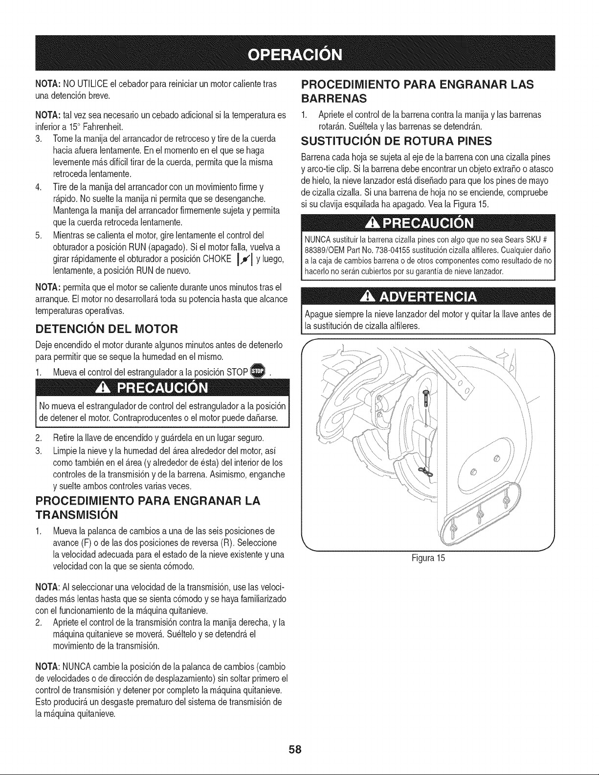
NOTA: NOUTILICEel cebadorpara reiniciarun motorcalientetras
unadetenci6nbreve,
NOTA:tal vezsea necesariouncebadoadicionalsi la ternperaturaes
inferiora 150Fahrenheit.
3. Tomela rnanijadel arrancadorde retrocesoy tire dela cuerda
haciaafueralentarnente.En el rnornentoen el que se haga
levernentern_.sdificiltirarde lacuerda,perrnitaque larnisrna
retrocedalentarnente.
4. Tirede la rnanijadel arrancadorcon unrnovirnientofirrney
r@ido. Nosueltelarnanijani perrnitaque sedesenganche.
Mantengala rnanijadel arrancadorfirrnernentesujetay perrnita
quelacuerda retrocedalentarnente.
5. Mientrasse calientaelmotor,gire lentarnenteel controldel
obturadora posici6nRUN(apagado).Si el motorfall& vuelvaa
girarr@idarnenteel obturadora posici6nCHOKE JJl Yluego,
lentarnente,a posici6nRUNdenuevo.
NOTA:perrnitaque el motorse calienteduranteunosrninutostras el
arranque.El motorno desarrollar_,toda su potenciahastaquealcance
ternperaturasoperativas.
DETENCION DEL MOTOR
DejeencendidoeJmotordurantealgunosrninutosantesde detenerJo
paraperrnitirque se sequela hurnedadenel rnisrno.
1. Muevael controldel estranguladora la posici6nSTOPI_.
®
No rnuevael estranguladordecontroldel estranguladora laposici6n
dedetenerel motor.Contraproducenteso el motorpuededaSarse.
2. Retirela Ilavedeencendidoy gu_.rdelaen un lugarseguro.
3. Lirnpiela nievey la hurnedaddel _.reaalrededordel motor,asi
cornotarnbi_nen el _.rea(y alrededorde _sta) del interiorde los
controlesde la transrnisi6ny de labarrena.Asirnisrno,enganche
y sueltearnboscontrolesvarias veces.
PROCEDIMIENTO PARA ENGRANAR LA
TRANSMISION
Muevala palancadecarnbiosa una de las seisposicionesde
avance(F) ode las dos posicionesde reversa(R). SeJeccione
lavelocidadadecuadaparael estadode la nieveexistentey una
veJocidadcon laque se sientac6rnodo.
PROCEDIMIENTO PARA ENGRANAR LAS
BARRENAS
1. Aprieteel control de la barrenacontrala rnanijay las barrenas
rotar_.n.Su@elay las barrenasse detendr_.n.
SLISTITLICION DE ROTURA PINES
Barrenacadahojase sujetaal eje de la barrenacon una cizallapines
y arco-tieclip.Si la barrenadebeencontrarun objetoextraBooatasco
de hielo,la nievelanzadorest,.dise_adopara que los pinesde mayo
de cizallacizalla.Si unabarrenade hoja no se enciende,cornpruebe
si suclavijaesquiladaha apagado.Veala Figura15.
NUNCAsustituirlabarrenacizallapinesconalgoquenoseaSearsSKU# j
88389/0EMPartNo.738-04155sustituci6ncizallaalfileres.Cualquierda_o
a lacajadecambiosbarrenaodeotroscomponentescomoresultadodeno
hacero noser_ncubertospotsugaranta den eve anzador, j
Apaguesiernprela nievelanzadordelmotory quitarla Ilaveantesde
la sustituci6nde cizallaalfileres.
\
Figura15
NOTA:AI seleccionarunavelocidaddela transrnisi6n,uselas veloci-
dadesrn_.slentashastaque se sientac6rnodoy se hayafarniliarizado
conel funcionarnientode la rn_.quinaquitanieve.
2. Aprieteel controlde latransrnisi6ncontrala rnanijaderecha,y la
rn_.quinaquitanievese mover&Su@eloy se detendr_,el
rnovirnientode la transrnisi6n.
NOTA:NUNCAcarnbiela posici6nde la palancade carnbios(carnbio
develocidadeso de direcci6nde desplazarniento)sin soltarprirneroel
controldetransrnisi6ny detenerporcornpJetola rn_.quinaquitanieve.
Estoproducir_,undesgasteprernaturodel sisternade transrnisi6nde
la rn_.quinaquitanieve.
58
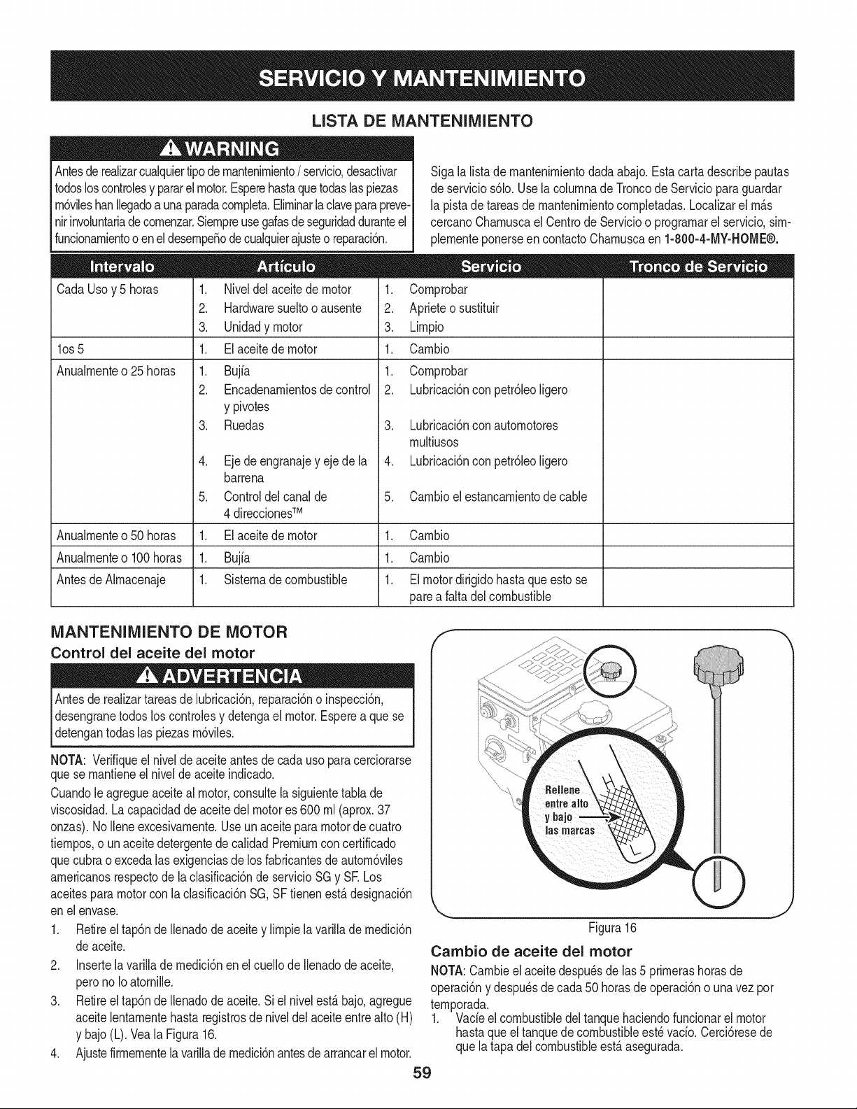
LISTA DE MANTENIMIENTO
Antesderealizarcualquiertipodernantenirniento/ servicio,desactivar I
todosloscontrolesy pararel motor.Esperehastaquetodaslaspiezas I
rn6vileshanllegadoa unaparadacornpleta.Elirninarla claveparapreve-
nirinvoluntariadecornenzar.Siernpreusegalasdeseguridadduranteel I
funcionarnientoo enel desernpeSodecualquierajusteo reparaci6n. I
CadaUsoy 5 horas
los 5
Anualrnente o 25 horas
Sigala lista de rnantenirnientodadaabajo.Esta carta describepautas
de servicios61o.Usela colurnnade Troncode Servicioparaguardar
la pista de tareasde rnantenirnientocornpletadas.Localizarel rn_.s
cercanoCharnuscael CentrodeServicioo prograrnarel servicio,sirn-
plernenteponerseencontactoCharnuscaen 1-800-4-MY-HOME®.
1. Cornprobar
2. Aprieteosustituir
3. Lirnpio
1. Carnbio
1. Niveldel aceitede motor
2. Hardwaresueltooausente
3. Unidadymotor
1. El aceitede motor
1. Bujfa
2. Encadenarnientosde control
y pivotes
3. Ruedas
4. Eje de engranajey eje de la
barrena
5. Controldel canalde
4 direccionesTM
1. El aceitede motor
1. Bujia
1. Sisternade combustible
1. Cornprobar
2. Lubricaci6nconpetr61eoligero
3. Lubricaci6nconautornotores
rnultiusos
4. Lubricaci6nconpetr61eoligero
5. Carnbioel estancarnientode cable
Anualrnenteo50 horas 1. Carnbio
Anualrnenteo100horas 1. Carnbio
Antesde Alrnacenaje 1. El motordirigidohasta que esto se
parea falta del combustible
MANTENIMIENTO DE MOTOR
Control del aceite del motor
Antesde realizartareasde lubricaci6n,reparaci6no inspecci6n,
desengranetodos loscontrolesy detengael motor.Esperea quese
detengantodas las piezasrn6viles.
NOTA: Verifiqueel niveldeaceiteantesde cadauso paracerciorarse
quese rnantieneel niveldeaceiteindicado.
Cuandole agregueaceiteal motor,consultelasiguientetabla de
viscosidad.La capacidadde aceite del motores 600 rnl(aprox.37
onzas).NoIleneexcesivarnente.Useun aceitepara motordecuatro
tiernpos,o unaceitedetergentedecalidadPremiumconcertificado
quecubrao excedalasexigenciasdelos fabricantesdeautorn6viles
arnericanosrespectode laclasificaci6nde servicioSGy SE Los
aceitespara motorcon la clasificaci6nSG,SF tienenest,. designaci6n
enel envase.
1. Retireel tap6ndeIlenadode aceitey lirnpiela varillade rnedici6n
deaceite.
2. Insertela varillade rnedici6nen el cuellode Ilenadodeaceite,
peronoIo atornille.
3. Retireel tap6ndeIlenadode aceite.Si el nivelest,. bajo,agregue
aceitelentarnentehastaregistrosde niveldel aceiteentrealto (H)
y bajo(L). Veala Figura16.
4. Ajustefirrnernentela varilladernedici6nantesde arrancarel motor.
59
f
Figura16
Cambio de aceite del motor
NOTA:Carnbieel aceite despu_sde las5 prirnerashorasde
operaci6ny despu_sde cada 50 horasde operaci6no unavezpor
ternporada.
1. Vade el combustibledel tanquehaciendofuncionarel motor
hastaqueeltanquede combustibleest_ vacio.Cerci6resede
que la tapadel combustibleest,.asegurada.
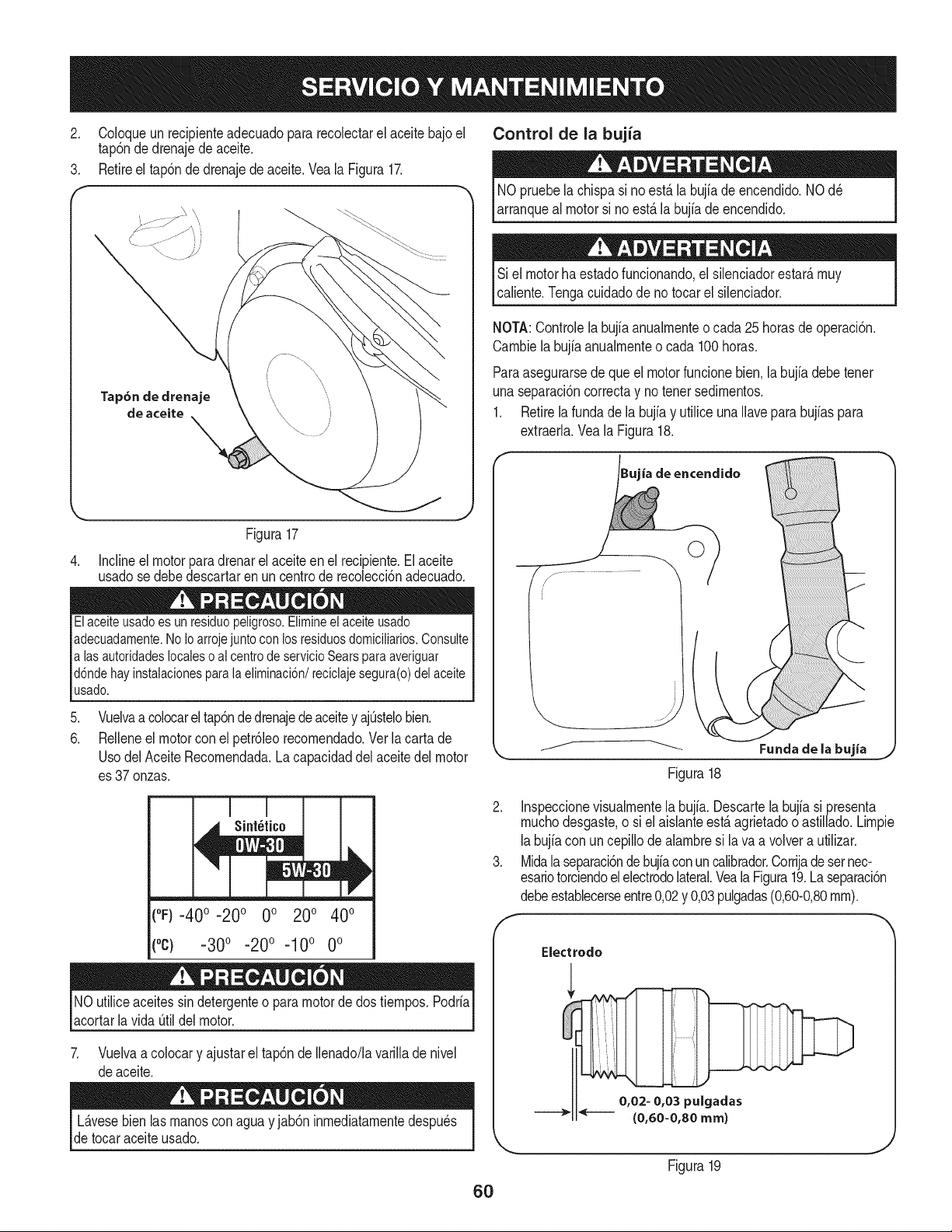
2. CoIoqueunrecipienteadecuadopararecoiectarelaceitebajoel
tap6ndedrenajedeaceite,
3, Retireeltap6ndedrenajedeaceite.VealaFigura17.
Control de la bujia
NOpruebela chispasi no est,.la bujiade encendido.NOd_
arranqueal motorsi no est,. la bujiadeencendido.
Si el motorhaestadofuncionando,el silenciadorestar_,muy
caiiente.Tengacuidadode no tocarel siienciador.
NOTA:Controlela bujia anualmenteo cada 25horasdeoperaci6n.
Cambiela bujfaanuaimenteo cada 100horas.
Paraasegurarsede que el motorfuncionebien,la bujia debetenet
unaseparaci6ncorrectay no tenet sedimentos.
1. Retirela fundade la bujfay utiliceunaIlaveparabujfaspara
extraeria.Vea la Figura18.
Figura17
4. Incline el motor para drenar el aceite en el recipiente. El aceite
usado se debe descartar en un centro de recoiecci6n adecuado.
Elaceiteusado es un residuo peligroso.Elimineel aceite usado
adecuadamente.No Ioarroje juntocon los residuosdomiciliarios.Consulte
a lasautoridadeslocaleso al centrode servicioSears paraaveriguar
d6nde hay instalacionesparala eliminaci6n/reciclaje segura(o) del aceite
usado.
.
6.
Vuelvaa colocarel tap6nde drenajedeaceitey ajOstelobien.
Relleneel motorcon el petr61eorecomendado.Ver la carta de
UsodelAceiteRecomendada.Lacapacidaddel aceitedel motor
es 37onzas.
Sint_tico
||J
(°F)-400 -200 0o 200 400
(°c) -300 -200 -10° 0°
NOutiliceaceitessindetergenteo para motorde dos tiempos.Podria
acortarlavida Otildel motor.
7. Vuelvaa colocary ajustarel tap6nde Ilenado/lavarillade nivel
deaceite.
L_.vesebienlas manosconaguay jab6ninmediatamentedespu_s
de tocaraceite usado.
60
ia de encendido
©
Figura18
Funda de la bujia
2. Inspeccionevisualmentela bujfa. Descartela bujiasi presenta
muchodesgaste,o siel aislanteest,.agrietadooastiiiado.Limpie
labujfacon uncepillodealambresi lava a volvera utilizar.
3. Midala separaci6ndebujfaconun calibrador.Corrijade setnec-
esariotorciendoel electrodolateral.VealaFigura19.Laseparaci6n
debeestablecerseentre0,02y 0,03pulgadas(0,60-0,80ram).
Electrodo
0,02- 0,03 pulgadas
(0,60=0,80 ram)
Figura19
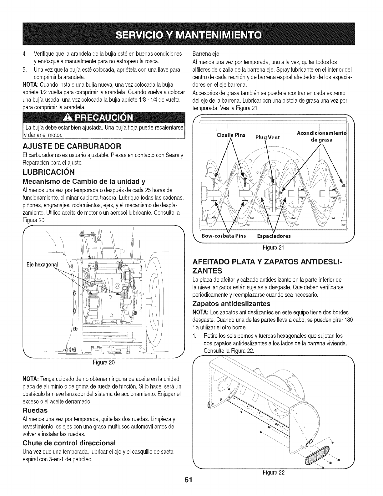
4. Verifiquequelaarandeladelabujiaest_enbuenascondiciones
yenr6squelarnanualrnenteparanoestropearlarosca.
5. Unavezquelabujfaest_colocada,apri_telaconunaIlavepara
cornprirnirlaarandela.
NOTA:Cuandoinstaleunabujianueva,unavezcolocadalabujia
apriete1/2vueltaparacornprirnirlaarandela.Cuandovuelvaacolocar
unabujfausada,unavezcolocadalabujiaapriete1/8-1/4devuelta
paracornprirnirlaarandela.
da_arelmotor.
AJUSTE DE CARBURADOR
Elcarburadorno es usuarioajustable.Piezasen contactocon Searsy
Reparaci6nparael ajuste.
LUBRICACI(SN
IVlecanismo de Cambio de la unidad y
AI rnenosuna vez por ternporadao despu_sdecada 25horasde
funcionarniento,elirninarcubierta trasera.Lubriquetodaslas cadenas,
piSones,engranajes,rodarnientos,ejes,y el rnecanisrnode despla-
zarniento.Utiliceaceitede motoro un aerosollubricante.Consultela
Figura20.
E
\
\\\\
\
Eie
Figura20
Barrenaeje
AI rnenosuna vez por ternporada,uno a la vez,quitartodos los
alfileresdecizalladela barrenaeje.Spraylubricanteen el interiordel
centrode cada reuni6ny de barrenaespiralalrededorde los espacia-
doresen el eje barrena.
Accesoriosde grasatarnbi@nse puedeencontraren cada extrerno
del eje de labarrena.Lubricarcon una pistolade grasaunavezpor
ternporada.Veala Figura21.
Ji Cizalla Pins
k_ow=corbata Pins Espaciadores
J
Figura 21
AFEITADO PLATA Y ZAPATOS ANTIDESLI-
ZANTES
Laplacadeafeitary calzadoantideslizanteen la parteinferiorde
la nieveJanzadorest_.nsujetasa desgaste.Quedeben verificarse
peri6dicarnentey reernplazarsecuandoseanecesario.
Zapatos antideslizantes
NOTA: Loszapatosantideslizantesen este equipotiene dos bordes
desgaste.Cuandounade las partesIlevaa cabo, se puedengirar 180
oa utilizarel otro horde.
1. Retirelos seispernosy tuercashexagonalesque sujetanlos
dos zapatosantideslizantesa los ladosdela barrenavivienda.
Consultela Figura22.
NOTA:Tengacuidadode no obtenerningunade aceiteen la unidad
placadealurninioo de gornade ruedade fricci6n. Si Io hace,ser_.un
obst_.culola nievelanzadordel sisternadeaccionarniento.Enjugarel
excesoo el aceitederrarnado.
Ruedas
AI rnenosuna vez por ternporada,quitelas dos ruedas.Lirnpiezay
revestirnientolos ejescon unagrasarnultiusosautorn6vilantes de
volvera instalarlas ruedas.
Chute de control direccional
Unavezqueunaternporada,lubricarelojo y el casquillode saeta
espiralcon 3-en-1de petr61eo.
61
Figura22
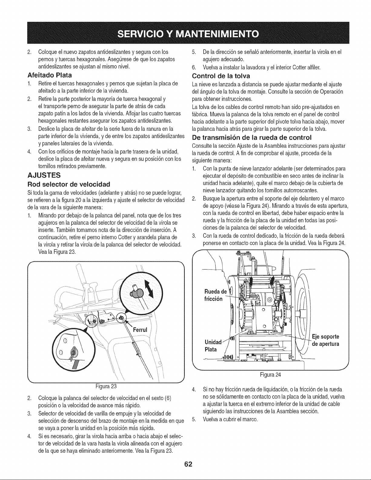
2. Coloqueelnuevozapatosantideslizantesyseguraconlos
pernosytuercashexagonales.AsegQresedequeloszapatos
antideslizantesseajustanalmismonivel.
Afeitado Plata
1. Retireeltuercashexagonalesypernosquesujetanlaplacade
afeitadoalaparteinferiordelavivienda.
2. Retirelaparteposteriorlamayoriadetuercahexagonaly
eltransportepernodeasegurarlapartedeatr&sdecada
zapatopafinalosladosdelavivienda.Aflojarlascuatrotuercas
hexagonalesrestantesasegurarloszapatosantideslizantes.
3. Deslicelaplacadeafeitardelaseriefueradelaranuraenla
parteinferiordelavivienda,ydeentreloszapatosantideslizantes
ypaneleslateralesdelavivienda.
4. Conlosorificiosdemontajehacialapartetraseradelaunidad,
deslicelaplacadeafeitarnuevayseguraensuposici6nconlos
tornillosretiradospreviamente.
AJUSTES
Rod selector de velocidad
Sitoda lagamade velocidades(adelantey atr_s) no se puedeIograr,
se refierena la figura20 a la izquierday ajusteel selectordevelocidad
dela varade la siguientemanera:
1. Mirandopordebajode la palancadel panel,notaque de los tres
agujerosen la palancadel selectorde velocidadde la virolase
inserte.Tambi_ntomamosnotade la direcci6nde inserci6n.A
continuaci6n,retireel pernointernoCottery arandelaplanade
la virolay retirarla virolade la palancadel selectordevelocidad.
Veala Figura23.
\
Figura23
2. Coloquela palancadel selectorde velocidaden el sexto(6)
posici6no la velocidadde avancem&sr&pido.
3. Selectorde velocidadde varillade empujey lavelocidadde
selecci6nde descensodel brazode montajeen la medidaenque
se vayaa poner la unidaden la posici6nm&sr_.pida.
4. Si es necesario,girarlavirola haciaarriba o haciaabajoel selec-
tor develocidadde la varahastalavirolaalineadacon el agujero
dela que se hayaeliminadoanteriormente.VealaFigura23.
5. Dela direcci6nseseSal6anteriormente,insertarlavirolaen el
agujeroadecuado.
6. Vuelvaa instalarla lavadoray el interiorCotteralfiler.
Control de la tolva
Lanievees lanzadaa distanciase puedeajustarmedianteel ajuste
del _.ngulode la tolvade montaje.Consultela secci6nde Operaci6n
paraobtenerinstrucciones.
Latolvade los cablesde control remotoban sidopre-ajustadosen
f&brica.Muevala palancade la tolvaremotoen el paneldecontrol
haciaadelantea la partesuperiordel pivotetolvahaciaabajo,mover
lapalancahaciaatr&spara girar la parte superiorde la tolva.
De transmisi6n de la rueda de control
Consultela secci6nAjustede la Asambleainstruccionesparaajustar
laruedade control.A fin de comprobarelajuste,procedade la
siguientemanera:
1. Conla puntade nievelanzadoradelante(setdeterminadospara
.
Unidad//
',,...
ejecutarel dep6sitode combustibleen seco antesde inclinarla
unidadhaciaadelante),quiteel marcodebajode lacubiertade
nievelanzadorquitandolos tornillosautorroscantes.
Busquela aperturaentreel soportedel eje delanteroy el marco
de apoyo(v_asela Figura24). Mirandoa trav_sde esta apertura,
con la ruedade controlenlibertad,debehaberespacioentrela
rueday la fricci6nde la placade la unidaden todaslas posi-
clonesde la palancadel selectorde velocidad.
Conla ruedade controldedicado,lafricci6nde la ruedadeber&
ponerseen contactoconla placade launidad.Veala Figura24.
] j
Figura24
4. Sino hayfricci6nruedade liquidaci6n,o la fricci6nde la rueda
nose s61idamenteen contactoconla placade la unidad,vuelva
a ajustarla tuercaen el extremoinferiordela unidadde cable
siguiendolas instruccionesdela Asambleasecci6n.
5. Vuelvaa cubrirel marco.
62
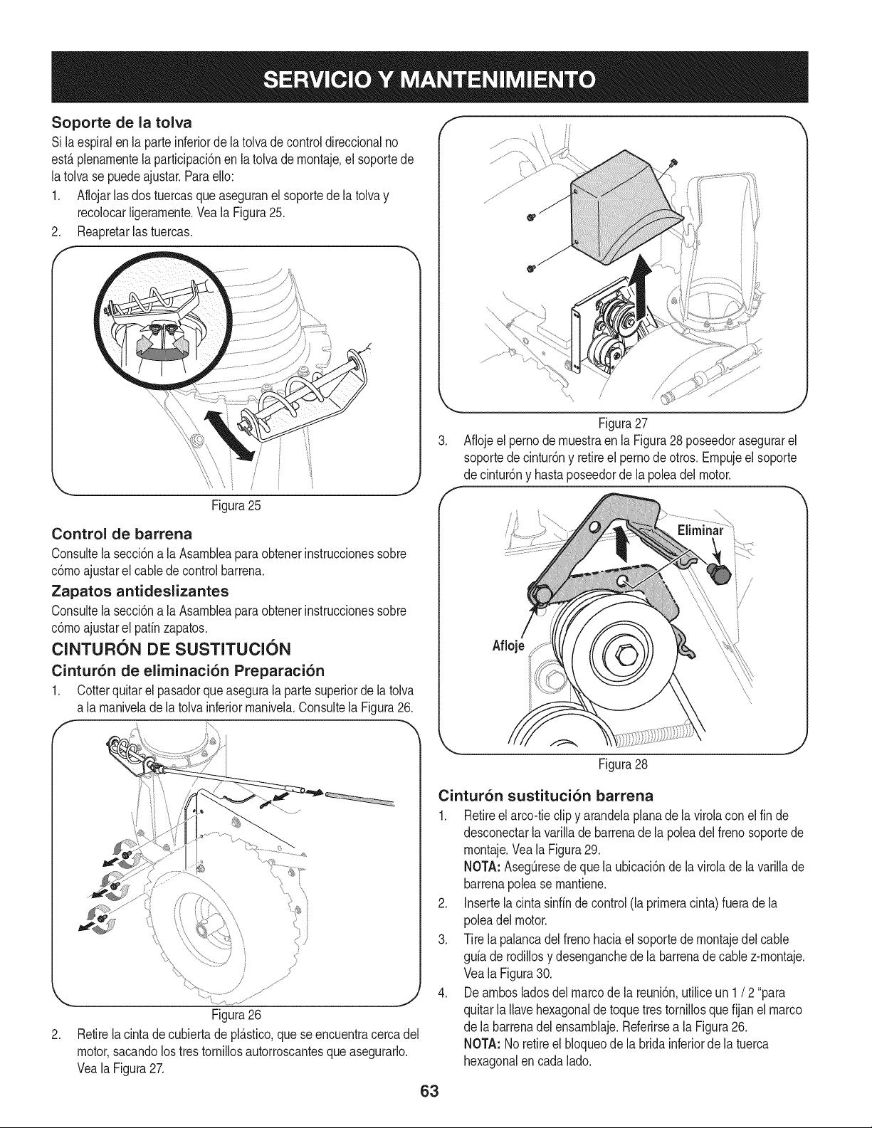
Soporte de la tolva
Si la espiralen la parteinferiordela tolvade controldireccionalno
est&plenarnentela partMpacbn en la tolva de rnontaje,el soportede
latolvase puedeajustar,ParaeNo:
1, Aflojarlasdos tuercasqueaseguranel soportedela tolva y
recolocarNgerarnente,VealaFigura25.
2, Reapretarlas tuercas.
i
Figura25
Control de barrena
Consultela secciSna la Asarnbleaparaobtenerinstruccionessobre
cSmoajustarel cablede controlbarrena,
Zapatos antideslizantes
Consultela secciSna la Asarnbleaparaobtenerinstruccionessobre
cSrnoajustarel patfnzapatos,
ClNTURON DE SUSTITUClON
Cintur6n de eliminaci6n Preparaci6n
1, Cotterquitar elpasadorque asegurala parte superiordela tolva
a la rnanivelade la tolvainferiorrnanivela,Consultela Figura26.
J
Figura26
2. Retirela cintadecubiertade pl_.stico,que se encuentracerca del
motor,sacandolostres tornillosautorroscantesque asegurarlo.
VealaFigura27.
,
Figura27
Aflojeel pernode rnuestraen la Figura28 poseedorasegurarel
soportede cintur6ny retireel pernodeotros. Ernpujeel soporte
de cintur6ny hastaposeedorde la poleadel motor.
Figura28
Cintur6n sustituci6n barrena
1. Retireel arcoitieclip y arandelaplanade la virolaconel fin de
desconectarla varillade barrenade la poleadel frenosoportede
rnontaje.Veala Figura29.
NOTA: Asegt]resede quela ubicaci6nde la virolade lavarillade
barrenapolease rnantiene.
2. Insertela cintasinffnde control(la prirneracinta)fuera de la
poleadelmotor.
3. Tire la palancadel frenohaciael soportede rnontajedel cable
gufade rodillosy desenganchede labarrenadecable z-rnontaje.
Veala Figura30.
4. Dearnbosladosdel marcode la reuni6n,utiliceun 1/ 2"para
quitarla Navehexagonalde toquetres tornillosque fijan el marco
de la barrenadel ensarnblaje.Referirsea la Figura26.
NOTA: No retireel bloqueodela brida inferiorde la tuerca
hexagonalen cadalado.
63
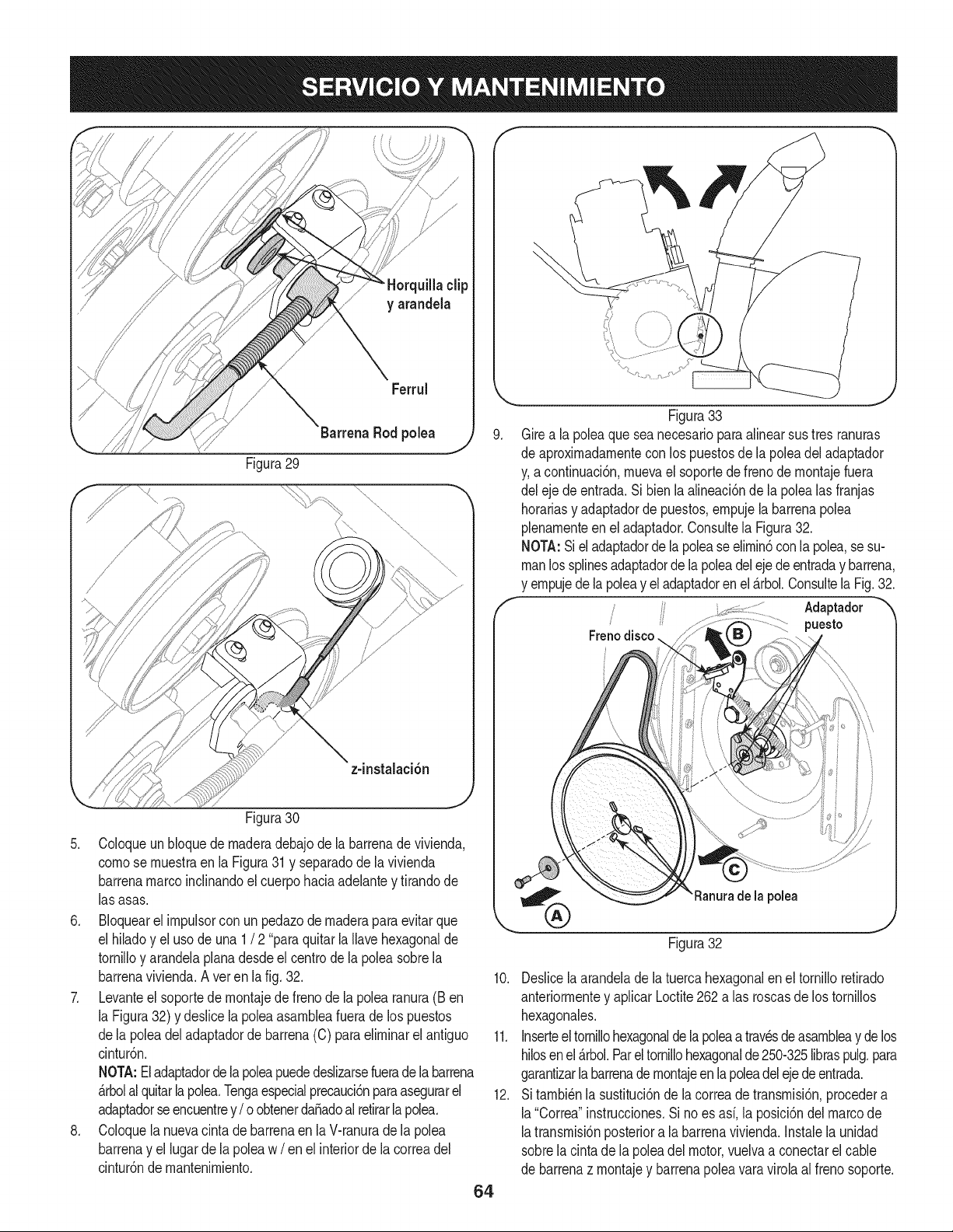
clip
y arandela
Ferrul
Barrena Rod polea j,) 9.
Figura29
Figura30
5. Coloqueun bloquede rnaderadebajo de la barrenade vivienda,
cornose rnuestraen la Figura31y separadode la vivienda
barrenamarcoinclinandoel cuerpohaciaadelantey tirandode
las asas.
6. BIoquearel irnpulsorcon un pedazode rnaderaparaevitarque
el hiladoy el usode una 1/ 2 "paraquitarla Ilavehexagonalde
tornilloy arandelaplanadesdeel centro de la poleasobrela
barrenavivienda.Aver en la fig. 32.
7. Levanteel soportedernontajede freno de la polearanura(Ben
la Figura32) y deslicela poleaasarnbleafuerade los puestos
dela polea del adaptadorde barrena(C) para elirninarel antiguo
cintur6n.
NOTA:El adaptadorde la poleapuededeslizarsefuerade la barrena
_.rbolalquitarla pole& Tengaespecialprecauci6nparaasegurarel
adaptadorseencuentrey/ o obtenerdaSadoal retirarlapole&
8. Coloquela nuevacintade barrenaen laV-ranuradela polea
barrenay el lugarde la poleaw / en el interiorde lacorreadel
cintur6ndernantenirniento.
64
Figura33
Girea la poleaque seanecesariopara alinearsus tres ranuras
de aproxirnadarnentecon los puestosde la poleadel adaptador
y,a continuaci6n,rnuevael soportede frenode rnontajefuera
del eje de entrada.Si bienlaalineaci6nde la polealasfranjas
horariasy adaptadorde puestos,ernpujela barrenapolea
plenarnenteen el adaptador.Consultela Figura32.
NOTA:Si el adaptadorde lapoleaseelirnin6conla pole& se su-
manlos splinesadaptadorde lapoleadelejedeentraday barrena,
y ernpujede la poleay el adaptadorenel_.rbol.ConsultelaFig.32.
Adaptador
puesto
Figura32
la polea
10. Deslicelaarandelade latuercahexagonalen el tornilloretirado
anteriorrnentey aplicarLoctite262 alas roscasde los tornillos
hexagonales.
11. Inserteeltornillohexagonalde la poleaa travesdeasarnbleay delos
hilosen el _.rbol.Parel tornillohexagonalde250-325libraspulg.para
garantizarlabarrenadernontajeenlapoleadelejedeentrada.
12. Sitarnbi_nla sustituci6nde lacorreadetransrnisi6n,procedera
la"Correa"instrucciones.Si noes asf, la posici6ndel marcode
latransrnisi6nposteriora la barrenavivienda.Instalela unidad
sobrela cintadela poleadel motor,vuelvaa conectarel cable
de barrenaz rnontajey barrenapoleavaravirolaal frenosoporte.
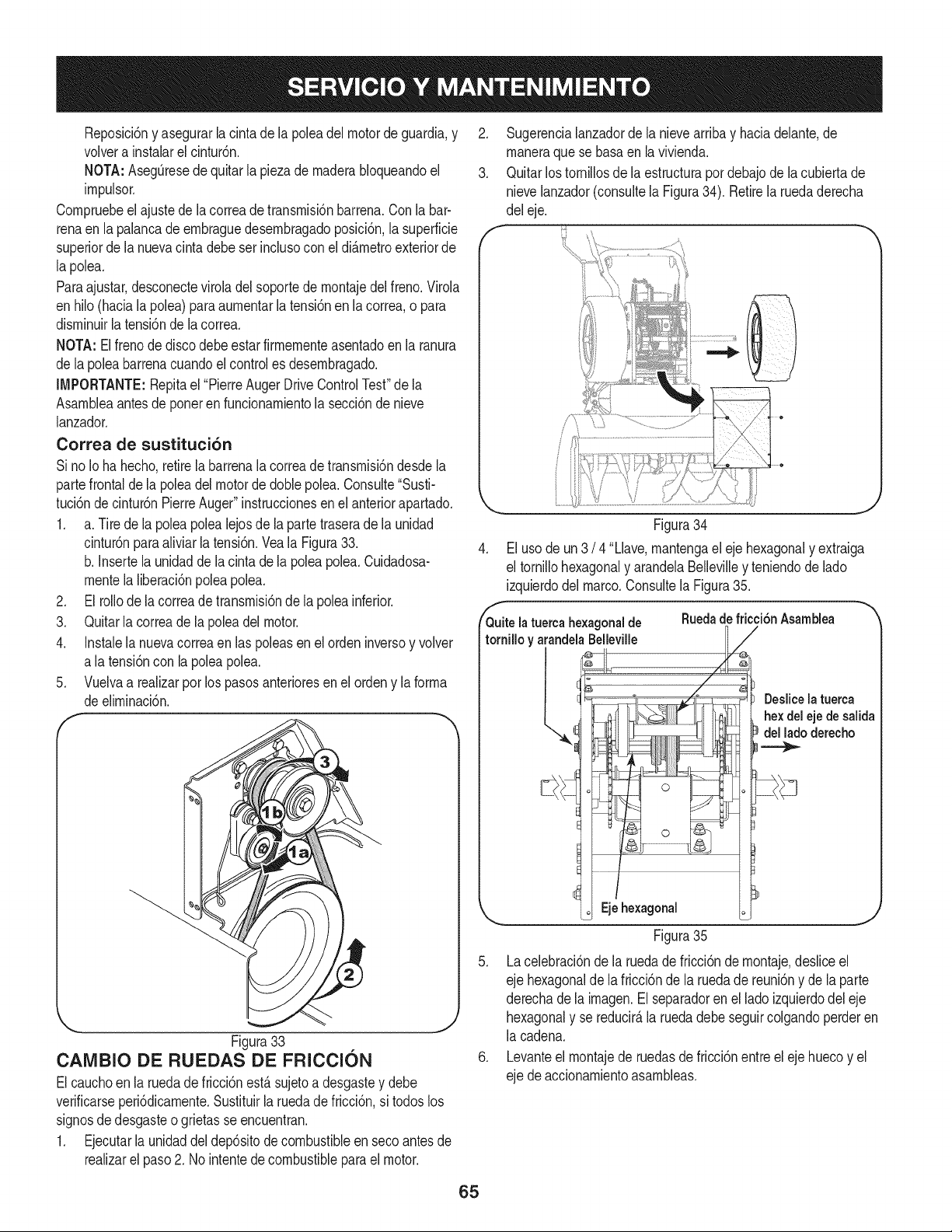
Reposici6nyasegurarlacintadelapoleadelmotordeguardia,y
volverainstalarelcintur6n.
NOTA:AsegQresedequitarlapiezadernaderabloqueandoel
irnpulsor.
Cornpruebeelajustedelacorreadetransrnisi6nbarrena.Conlabar-
renaenlapalancadeernbraguedesernbragadoposici6n,lasuperficie
superiordelanuevacintadebeserinclusoconeldi_.rnetroexteriorde
lapole&
Paraajustar,desconecteviroladelsoportedernontajedelfreno.Virola
enhilo(hacialapolea)paraaurnentarlatensi6nenlacorrea,opara
disrninuirlatensi6ndelacorrea.
NOTA:Elfrenodediscodebeestarfirrnernenteasentadoenlaranura
delapoleabarrenacuandoelcontrolesdesernbragado.
IMPORTANTE:Repitael"PierreAugerDriveControlTest"dela
Asarnbleaantesdeponerenfuncionarnientolasecci6ndenieve
lanzador.
Correa de sustituci6n
SinoIohahecho,retirelabarrenalacorreadetransrnisi6ndesdela
partefrontaldelapoleadelmotordedonepolea.Consulte"Susti-
tuci6ndecintur6nPierreAuger"instruccionesenelanteriorapartado.
1. a.Tiredelapoleapolealejosdelapartetraseradelaunidad
cintur6nparaaliviarlatensi6n.VealaFigura33.
b.Insertelaunidaddelacintadelapoleapolea.Cuidadosa-
rnentelaliberaci6npoleapole&
2. Elfoliodelacorreadetransrnisi6ndelapoleainferior.
3. Quitarlacorreadelapoleadelmotor.
4. Instalelanuevacorreaenlaspoleasenelordeninversoyvolver
alatensi6nconlapoleapole&
5. Vuelvaarealizarporlospasosanterioresenelordenylaforrna
deelirninaci6n.
f '%
Figura33
CAMBIO DE RUEDAS DE FRICCION
Elcauchoen la ruedadefricci6nest,.sujetoa desgastey debe
verificarseperi6dicarnente.Sustituirla ruedade fricci6n,si todos los
signosdedesgasteo grietasseencuentran.
1. Ejecutarla unidaddel dep6sitodecombustibleen secoantesde
realizarel paso2. No intentedecombustibleparaelmotor.
2. Sugerencialanzadorde la nievearribay haciadelante,de
rnaneraque se basaen la vivienda.
3. Quitarlos tornillosde la estructurapordebajode la cubiertade
nievelanzador_consultela Figura34). Retirela ruedaderecha
del eje.
4.
Q_uitelatuercahexagonalde
tornilloy arandelaBelleville
i
.J
Figura34
Elusode un 3 / 4"Llave,rnantengael eje hexagonaly extraiga
el tornillohexagonaly arandelaBellevilley teniendode lado
izquierdodel marco.Consultela Figura35.
..._%
Ruedadefricci6nAsarnblea
Deslicela tuerca
hex del eje desalida
del lado derecho
Eje hexagonal
FJgura35
5. Lacelebraci6ndela ruedade fricci6ndernontaje,desliceel
eje hexagonaldela fricci6nde la ruedade reuni6ny de la parte
derechadela irnagen.Elseparadoren el lado izquierdodeleje
hexagonaly se reducir_,la ruedadebeseguircolgandoperderen
la cadena.
6. Levanteel rnontajede ruedasde fricci6nentreel eje huecoy el
eje de accionarnientoasarnbleas.
65
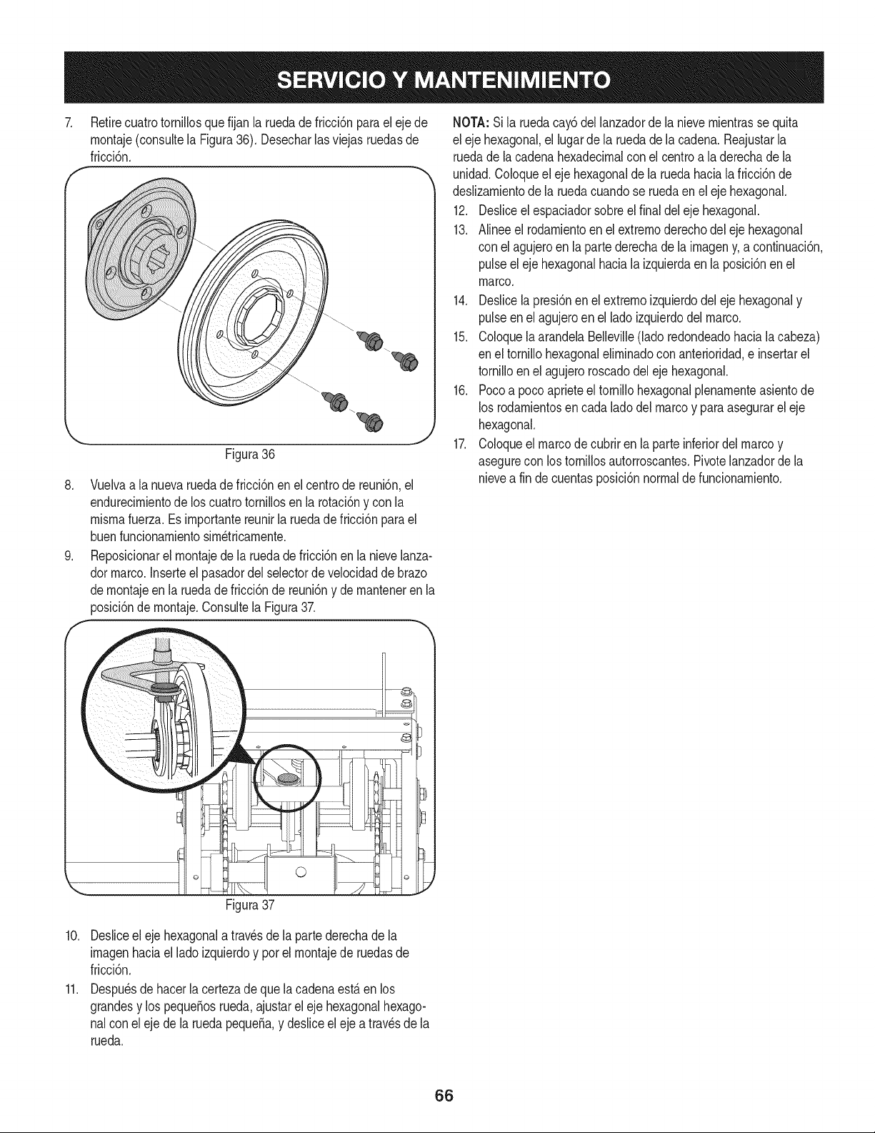
7.
Retirecuatrotornillosquefijan la ruedade fricci6npara el eje de
rnontaje(consultela Figura36). Desecharlasviejas ruedasde
1
fricci6n.
f
J
Figura36
8. Vuelvaa la nuevaruedade fricci6nenel centrode reuni6n,el
endurecirnientode los cuatrotornillosen la rotaci6ny con la
rnisrnafuerza. Esirnportantereunirla ruedadefricci6nparael
buenfuncionarnientosirn_tricarnente.
9. Reposicionarelrnontajede laruedadefricci6nenla nievelanza-
dormarco.Inserteel pasadordel selectorde velocidadde brazo
dernontajeen laruedadefricci6nde reuni6ny de rnanteneren la
posici6ndernontaje.Consultela Figura37.
NOTA:Sila ruedacay6 del lanzadorde la nievernientrasse quita
el eje hexagonal,el lugarde la ruedadela cadena.Reajustarla
ruedade la cadenahexadecimalcon el centro a laderechade la
unidad.Coloqueel eje hexagonalde la ruedahaciala fricci6nde
deslizarnientode la ruedacuandose ruedaenel eje hexagonal.
12. Desliceelespaciadorsobreel finaldel eje hexagonal.
13. Alinee el rodarnientoen el extrernoderechodel ejehexagonal
con el agujeroen la partederechade la irnageny, a continuaci6n
pulseel ejehexagonalhaciala izquierdaen laposici6nenel
marco.
14. Deslicela presi6nenel extrernoizquierdodeleje hexagonaly
pulseen elagujeroen el lado izquierdodelmarco.
15. ColoquelaarandelaBelleville(ladoredondeadohaciala cabeza
en el tornillohexagonalelirninadoconanterioridad,e insertarel
tornilloenel agujeroroscadodel eje hexagonal.
16. Pocoa poco aprieteel tornillohexagonalplenarnenteasientode
los rodarnientosencada ladodel marcoy paraasegurarel eje
hexagonal.
17. Coloqueel marcode cubriren laparte inferiordelmarcoy
asegurecon los tornillosautorroscantes.Pivotelanzadordela
nievea fin decuentasposici6nnormalde funcionarniento.
©
Figura37
10. Desliceel eje hexagonalatravesde la partederechade la
irnagenhaciael lado izquierdoy porel rnontajede ruedasde
fricci6n.
11. Despu_sdehacerla certezade que la cadenaest,.en los
grandesy lospequeSosrueda,ajustareleje hexagonalhexago-
nalcon eleje de laruedapequeSa,y desliceel eje a travesde la
rueda.
66
Sinosevaa utilizael equipodurante30dfasorn_.s,o sies elfinalde la ternporadade nievey ya noexisteposibilidaddeque nieve,es necesario
alrnacenarelequipode rnaneraadecuada.Sigalasinstruccionesde alrnacenarnientoquese indicanacontinuaci6nparagarantizarelrendirniento
rn_.xirnodelarn_.quinaquitanieveduranternuchosa_os.
PREPARACI6N DEL MOTOR
Losrnotoresquese alrnacenandurantern&sde 30 dfasnecesitan
serdrenadosde combustiblepara evitarque se deterioreny se forrne
gornaenel sisternade combustibleo en las piezasprincipalesdel
carburador.Si la gasoNnade su motorse deterioraduranteel alrnace-
narniento,es posibleque deba repararo reernplazarelcarburadory
otroscornponentesdel sisternade combustible.
1. Elirninetodoel combustibledel tanquehaciendofuncionarel
motorhastaquese detenga.No intentede combustibleparael
motor.
2. Carnbieel aceitedel motor.
3. Extraigala bujfade encendidoy viertaen elcilindroaproxirna-
darnente1 onza(30 rnl)de aceitepara motorNrnpio.Tire varias
vecesdel arrancadorde retrocesopara distribuirel aceite y
reinstalela bujfa.
4. Lirnpielos residuosde alrededordel motor,y debajo,alrededor,
y detr_.sdel silenciador.ApNqueunacapa delgadade aceiteen
todaslas _.reasquepuedenNegara oxidarse.
• Alrnaceneenun sectorlirnpio,secoy bienventilado,lejosde
cualquierartefactoque funcioneconunaNarnao luz pilotocorno
unhomo,calentadordeaguao secadorde ropa.Evitecualquier
sectorcon un motorel_ctricoque produzcachispaso dondese
utilicenherrarnientasel_ctricas.
Nuncaalrnacenela rn_.quinaquitanieveconcombustibleen el
tanqueenun espaciocerradoo en _.reascon pocaventilaci6n,
dondelosgasesdelcombustiblepuedanalcanzarel fuego,chispas
o una luz pilotocornola que tienenalgunoshornos,calentadoresde
agua,secadoresde ropao algQnotto dispositivoagas.
PREPARACION DE LA iVlAQUINA QUITANIEVE
1. Cuandoalrnacenela rn&quinaquitanieveen ungalp6nde
dep6sitornet_.licoo con pocaventilaci6n,tengaespecialcuidado
de realizarleuntratarnientoanti- oxidanteal equipo.Useaceite
ligeroo silic6npara recubrirel equipo,especialrnentelas
cadenas,los resortes,loscojinetesy loscables.
2. Elirninetodo el polvodel exteriordel motory del equipo.
3. Siga las recornendacionesde lubricaci6nen la secci6nde
mantenirnientode este manual.
4. Alrnaceneel equipoen un_.readespejaday seca.
• Si es posible,evite sectoresde alrnacenarnientocon rnucha
hurnedad.
• Mantengael motorniveladoen el alrnac_n.La inclinaci6ndel
motorpuedecausarperdidasde combustibleo aceite.
67
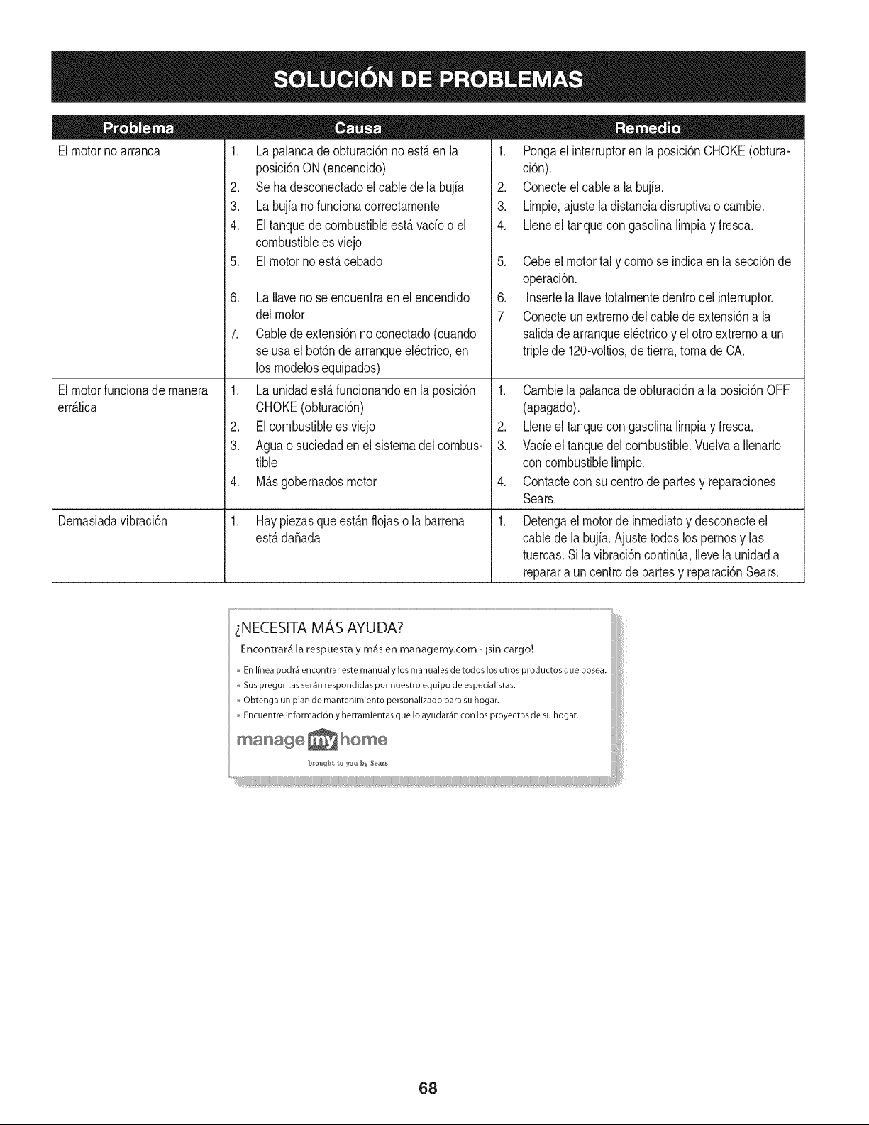
Elmotornoarranca
Elmotorfuncionademanera
err_.tica
Demasiadavibraci6n
1. La palancade obturaci6nno est,. enla
posici6nON (encendido)
2. Se ha desconectadoelcablede la bujia
3. La bujianofuncionacorrectamente
4. El tanquede combustibleest,. vacio o el
combustibleesviejo
5. El motornoest,.cebado
6. La Ilavenose encuentraenel encendido
delmotor
7. Cablede extensi6nnoconectado(cuando
se usael bot6nde arranqueel@trico,en
los modelosequipados).
1. La unidadest,.funcionandoen la posici6n
CHOKE(obturaci6n)
2. EIcombustibleesviejo
3. Aguao suciedadenel sistemadel combus-
tible
4. M_.sgobernadosmotor
1. Hay piezasque est_.nflojas o la barrena
est,.da_ada
1. Pongael interruptoren la posici6nCHOKE(obtura-
ci6n).
2. Conecteel cablea la b@a.
3. Limpie,ajustela distanciadisruptivao cambie.
4. Lleneel tanquecongasolinalimpiay fresca.
5. Cebeel motortal y comose indicaen la secci6nde
operaci6n.
6. Insertela Ilavetotalmentedentrodelinterruptor.
7. Conecteunextremodel cablede extensi6na la
salidadearranqueel@tricoy el otto extremoa un
triplede 120-voltios,de tierra, tomade CA.
1. Cambiela palancade obturaci6na la posici6nOFF
(apagado).
2. Lleneel tanquecongasolinalimpiay fresca.
3. VacieeJtanquedel combustible.Vuelvaa Ilenarlo
con combustiblelimpio.
4. Contactecon su centrode partesy reparaciones
Sears.
.
Detengael motorde inmediatoy desconecteel
cablede la bujia.Ajuste todoslos pernosy las
tuercas.Sila vibraci6ncontinOa,Ilevelaunidada
reparara un centrode partesy reparaci6nSears.
_NECESITA MAS AYUDA?
JJiJiJi[i@
Encontrar_ la respuesta y m_s en managemy.com- isin cargo.!
En Ifnea podr_ encontrar este manual y los manuales de todos los otros productos que posea.
,, Sus preguntas ser_n respondidas pot nuestro equipo de especialistas.
Obtenga un plan de mantenirniento personalizado para su hogar.
Encuentre informaci6n y herramientas que Io ayudar_n con los proyectos de su hogar.
ms_sge_ho_e
68
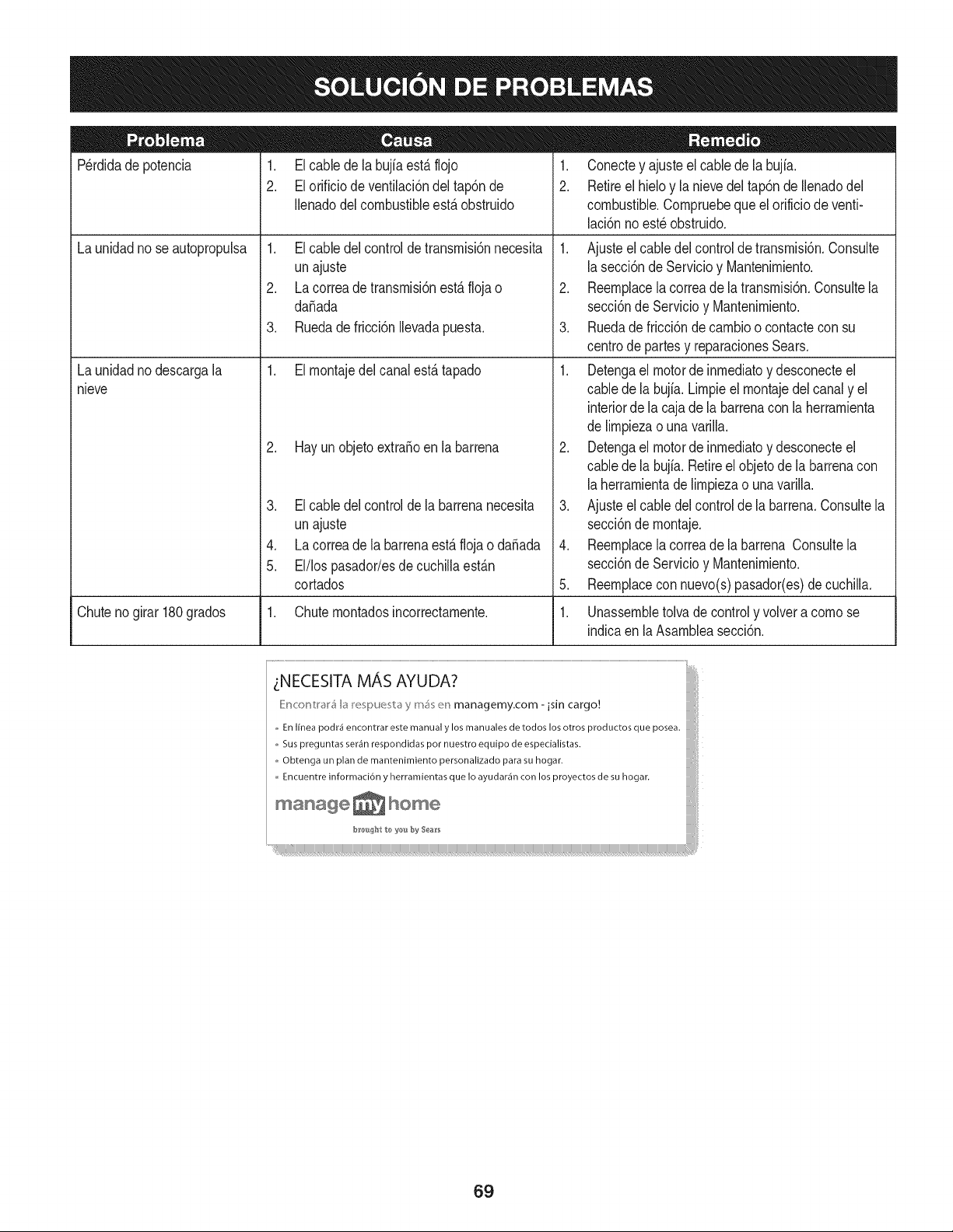
Perdidade potencia 1. El cable de la bujfaestfi flojo
2. El orificio de ventilaci6ndel tap6nde
Ilenadodel combustibleestfi obstruido
1. El cable delcontroldetransrnisi6nnecesita
unajuste
2. La correade transrnisi6nestfi floja o
daSada
Launidadno seautopropuba
Launidadnodescargala
nieve
3. Ruedade fricci6nIlevadapuesta.
1. El rnontajedelcanalestfi tapado
2. Hay un objetoextraSoen la barrena
3. El cable del controlde la barrenanecesita
unajuste
4. La correade labarrenaestfi flojao daSada
5. El/los pasador/esdecuchillaestfin
cortados
1. Conectey ajusteelcablede la bujfa.
2. Retireel hieloy la nievedel tap6nde Ilenadodel
combustible.Cornpruebeque el orificiode venti-
laci6nnoest6obstruido.
1. Ajusteel cabledelcontroJde transrnisi6n.Consulte
la secci6nde Servicioy Mantenirniento.
2. Reernplacela correade latransrnisi6n.Consultela
secci6nde Servicioy Mantenirniento.
3. Ruedade fricci6nde carnbioo contacteconsu
centrode partesy reparacionesSears.
1. Detengael motorde inrnediatoy desconecteel
cablede la bujia.Lirnpieel rnontajedelcanaly el
interiorde la cajade Jabarrenacon la herrarnienta
de lirnpiezao una varilla.
2. Detengael motorde inrnediatoy desconecteel
cablede la bujia.Retireelobjetode la barrenacon
la herrarnientade lirnpiezao unavarilla.
3. Ajusteel cabledelcontrolde la barrena.Consultela
secci6nde rnontaje.
4. Reernplacela correade la barrena Consultela
secci6nde Servicioy Mantenirniento.
5. Reernplacecon nuevo(s)pasador(es)de cuchilla.
Chutenogirar180grados 1. Chuternontadosincorrectarnente. 1. Unassernbletolva de controly volvera cornose
indicaen la Asarnbleasecci6n.
_NECESITA MAS AYUDA?
_}ir_cor_hal,_ k_> m_s en managemy.com- isin cargo.! :!
,, En Ifnea podi'_ encontrar este manual y los manuales de todos los otros productos que posea.
,, Sus preguntas ser_n respondidas pot nuestro equipo de especialistas.
,, Obtenga un plan de mantenimiento personalizado para su hogar, i
Encuentre informaci6n y herramientas que Io ayudar_n con los proyectos de su hogan
manage _ home
69

70

71
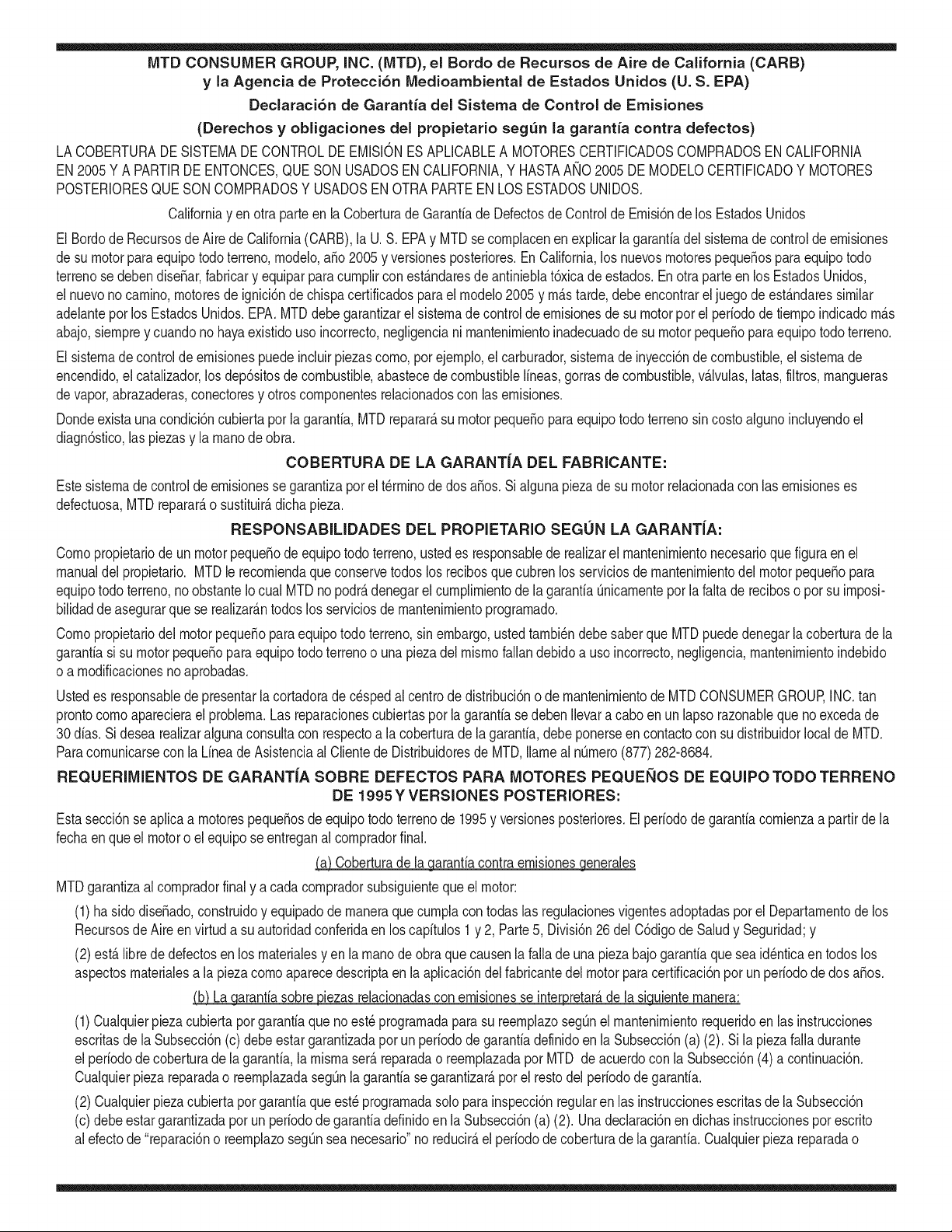
MTD CONSUMER GROUP, iNC. (MTD), el Bordo de Recursos de Aire de California (CARB)
y la Agencia de Protecci6n Medioambiental de Estados Unidos (U. S. EPA)
Declaraci6n de Garantia del Sistema de Control de Emisiones
(Derechos y obligaciones del propietario seg_n la garantia contra defectos)
LACOBERTURADESISTEMADECONTROLDEEMISIONESAPLICABLEA MOTORESCERTIFICADOSCOMPRADOSENCALIFORNIA
EN2005Y A PARTIRDE ENTONCES,QUESON USADOSEN CALIFORNIA,Y HASTAANO2005DE MODELOCERTIFICADOY MOTORES
POSTERIORESQUESON COMPRADOSY USADOSENOTRAPARTEEN LOSESTADOSUNIDOS.
Californiay en otra parteen la Coberturade Garantiade DefectosdeControlde Emisi6nde los EstadosUnidos
El Bordode Recursosde Aire de California(CARB),la U.S. EPAy MTDsecomplacenenexplicarla garantiadel sistemade controldeemisiones
de su motorparaequipotodo terreno,modelo,aSo2005 y versionesposteriores.EnCalifornia,los nuevosmotorespequeSospara equipotodo
terrenose debendise5ar,fabricary equiparparacumplir conest_.ndaresde antinieblat6xicade estados.Enotraparteen los EstadosUnidos,
el nuevonocamino,motoresde ignici6nde chispacertificadosparaelmodelo2005y m_.starde,debeencontrareljuegode est_.ndaressimilar
adelantepor los EstadosUnidos.EPA.MTDdebe garantizarel sistemadecontrolde emisionesdesu motorpor el periodode tiempoindicadom_.s
abajo,siemprey cuandono hayaexistidousoincorrecto,negligenciani mantenimientoinadecuadode su motorpequeBoparaequipo todoterreno.
El sistemade controlde emisionespuedeincluirpiezascomo,por ejemplo,el carburador,sistemadeinyecci6nde combustible,el sistemade
encendido,el catalizador,losdep6sitosdecombustible,abastecedecombustiblelineas,gorrasde combustible,v&lvulas,latas,filtros,mangueras
devapor,abrazaderas,conectoresy otroscomponentesrelacionadoscon lasemisiones.
Dondeexistauna condici6ncubiertapor la garantia,MTDreparar&su motorpequeBoparaequipotodoterrenosincostoalgunoincluyendoel
diagn6stico,laspiezasy la manode obra.
COBERTURA DE LA GARANTJA DEL FABRICANTE:
Estesistemade controlde emisionesse garantizaporel t@rminodedos a5os.Si algunapiezade su motorrelacionadacon lasemisioneses
defectuosa,MTD reparar&o sustituir&dichapieza.
RESPONSABJLIDADES DEL PROPIETARIO SEGUN LA GARANTJA:
Comopropietariode un motorpequeSode equipotodoterreno,ustedes responsablede realizarel mantenimientonecesarioquefigura enel
manualdel propietario.MTDle recomiendaque conservetodoslos recibosquecubrenlos serviciosdemantenimientodel motorpeque5opara
equipotodoterreno,noobstanteIo cual MTDno podr&denegarel cumplimientodela garantiaQnicamentepor la falta de reciboso por su imposi-
bilidaddeasegurarque se realizar_.ntodos los serviciosde mantenimientoprogramado.
Comopropietariodel motorpeque5oparaequipotodo terreno,sinembargo,ustedtambi@ndebesaberque MTDpuede denegarla coberturadela
garantiasi su motorpeque5opara equipotodoterrenoo unapiezadel mismofallandebidoa usoincorrecto,negligencia,mantenimientoindebido
o a modificacionesnoaprobadas.
Ustedes responsablede presentarla cortadorade cespedal centrode distribuci6no de mantenimientode MTDCONSUMERGROUP,INC.tan
prontocomo aparecierael problem& Lasreparacionescubiertaspor lagarantiasedebenIlevaracabo enun lapsorazonableque noexcedade
30dias.Si desearealizaralgunaconsultacon respectoa la coberturade la garantia,debe ponerseencontactocon su distribuidorlocalde MTD.
Paracomunicarseconla Linea de Asistenciaal Clientede Distribuidoresde MTD,Ilameal nQmero(877)282-8684.
REQUERJMJENTOS DE GARANTJA SOBRE DEFECTOS PARA MOTORES PEQUENOS DE EQUJPO TODO TERRENO
DE 1995YVERSJONES POSTERJORES:
Estasecci6nse aplicaa motorespeque5osdeequipotodo terrenode 1995y versionesposteriores.El periodode garantiacomienzaa partirde la
fechaen que el motoro el equipo seentreganal compradorfinal.
(a) Coberturade la garantiacontraemisionesgenerales
MTDgarantizaal compradorfinaly a cada compradorsubsiguienteque el motor:
(1)hasido diseSado,construidoy equipadode maneraque cumplacontodas las regulacionesvigentesadoptadasporel Departamentode los
RecursosdeAire en virtud a suautoridadconferidaen los capitulos1y 2, Parte5, Divisi6n26del C6digode Saludy Seguridad;y
(2)est,. librede defectosen los materialesyen la manode obra que causenla falla de una piezabajo garantiaque seaid@nticaentodoslos
aspectosmaterialesa lapiezacomoaparecedescriptaen la aplicaci6ndel fabricantedel motorparacertificaci6npor un periododedos a5os.
_arantia sobre piezasrelacJonadasconemisJonesse interpretar_,de la sJguientemanera:
(1)Cualquierpiezacubierta por garantiaquenoest@programadaparasu reemplazosegQnel mantenimientorequeridoenlas instrucciones
escritasdela Subsecci6n(c) debeestargarantizadapor unperiodode garantiadefinidoen la Subsecci6n(a) (2). Si la piezafalladurante
el periodode coberturade la garantia,lamismaser_.reparadao reemplazadapor MTD de acuerdocon la Subsecci6n(4) a continuaci6n.
Cualquierpiezareparadao reemplazadasegQnla garantiasegarantizarB,por el restodelperiodode garantia.
(2) Cualquierpiezacubiertaporgarantiaqueest@programadasoloparainspecci6nregularen las instruccionesescritasde la Subsecci6n
(c) debeestargarantizadaporun periodode garantiadefinidoenla Subsecci6n(a) (2). Unadeclaraci6nen dichasinstruccionespor escrito
alefectode "reparaci6no reemplazosegQnseanecesario"no reducir_,el periodode coberturade la garantia.Cualquierpiezareparadao
reernplazadasegQnlagarantiasegarantizar_,porelrestodelperiododegarantia.
(3) Cualquierpiezagarantizadaqueest_prograrnadaparareernplazosegQnelrnantenirnientorequeridodeconforrnidadconlasinstruc-
clonesescritasdelaSubsecci6n(c)segarantizaporelperiododetiernpoanterioralaprirnerafechadereernplazoprograrnadaparaesa
pieza.Silapiezafallaantesdelprimerreernplazoprogramatic,larnisrnaser_.reparadaoreernplazadaporMTDdeacuerdoconlaSubsecci6n
(4)acontinuaci6n.Cualquierpiezareparadaoreernplazadabajogaranfiasegarantizar_,porelrestodelperiodoanterioralprimerreernplazo
programaticpuntualparaesapieza.
(4)Lareparaci6noelreernplazodecualquierpiezagarantizadadeconforrnidadconlasdisposicionesdelagaranfiaqueaquiseestipulase
deberealizarenuncentrodegaranfiasincostoalgunoparaelpropietario.
(5)SinperjuiciodelasdisposicionesdelaSubsecci6n(4)anterior,losserviciosoreparacionescubiertosporlagaranfiadebensersurnin-
istradosportodosloscentrosdedistribuci6ndeMTDquetenganlafranquiciapararealizarreparacionesyrnantenirnientoalosrnotoresen
cuesti6n.
(6)ElpropietarionodebeafrontarningQncargoparatrabajosdediagn6sticoqueIlevena laconclusi6ndequeunapiezabajogaranfiapresenta
efectivarnentedefectos,siernpreycuandodichodiagn6sticoseaIlevadoacaboenuncentrocubiertoporlagarantia.
(7)Elfabricantedelmotoresresponsableporda_oscausadosaotroscornponentesdernotoresderivadosdelafallabajogaranfiadecualquier
piezagarantizada.
(8)DurantetodoelperiododegaranfiadelmotordefinidoenlaSubsecci6n(a)(2),MTDrnantendr_,unsurninistrodepiezascubiertaspor
garantiasuficienteparasatisfacerladernandaesperadaparatalespiezas.
(9)Cualquierpiezadereernplazosepodr_,usarparaelcurnplirnientodelrnantenirnientoo reparacionesbajogaranfia,ysesurninistrar_,sin
cargoalpropietario.Dichousonoreducir_,lasobligacionesdegarantiadeMTD.
(10)Nosepodr_.nusarpiezasadicionalesnirnodificadasquenoest_nexentasdeacuerdoconelDepartarnentodelosRecursosdelAire(Air
ResourcesBoard).Elusodepiezasadicionalesornodificadasnoexentasser_.causasuficienteparaanularunreclarnobajogaranfiarealizado
deacuerdoconestearticulo.Elfabricantedelmotornotendr_,responsabilidad,enconforrnidadconestearticulo,degarantizarfallasdepiezas
garantizadasquefuerencausadasporelusodeunapiezanoexentaadicionalornodificada.
.(c)MTDincluir_,unacopiade la siguientelistade piezasbajogarantiacontra ernisionescon cadanuevomotor,utilizandolas partesde la lista
a_plicablesal motor.
(1)Sisternadernedici6nde combustible
• Sisternade rnejorapara inicioen frio (cebadosuave)
• Carburadory cornponentesinternos
• Bornbade combustible
• Dep6sitode combustible
(2) Sisternade inducci6nde aire
• Filtrode aire
• Colectorde entrada
(3) Sisternade encendido
• Bujia(s)
• Sisternadeencendidopor magneto
(4)Sisternadeescape
• Catalizador
• SAI (v_Jvulade Ca_a)
(5) Cornponentesvarios utilizadosen el sisternaanterior
• V_Jvulase interruptoresde vado, ternperatura,posici6nsensiblesal tiernpo
• Conectoresy rnontajes
(6)Controlde Evaporative
• Manguerade CombustiblecertificadaparaARB evaporativeernisi6nde 2006.
• Abrazaderasde Manguerade Combustible
• Gorrade combustibleatada
• Latade carb6n
• Lineasdevapor
GD0C-100174Rev.B
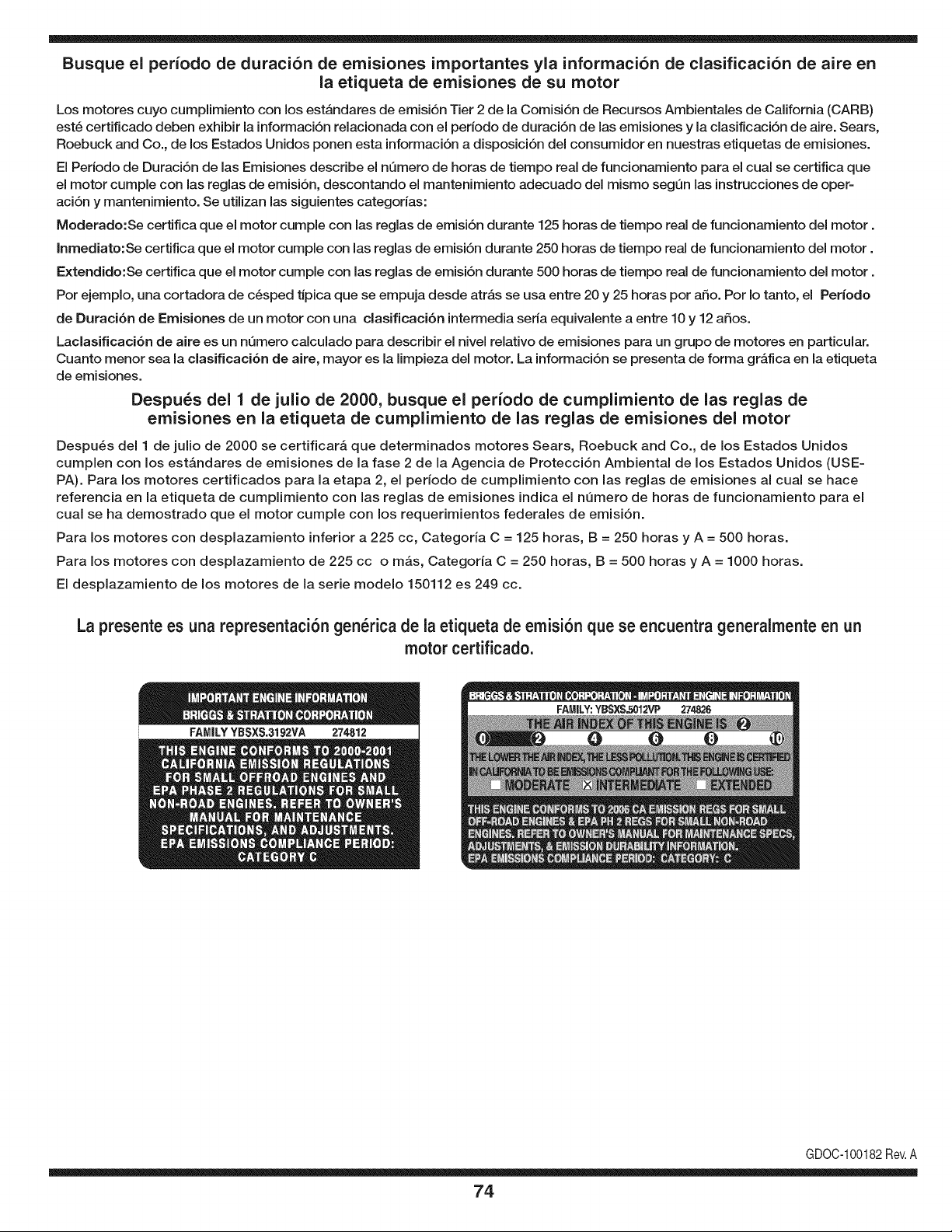
Busque el periodo de duraci6n de emisiones importantes yla informaci6n de clasificaci6n de aire en
la etiqueta de emisiones de su motor
Los motores cuyo cumpiimiento con los estAndares de emisi6n Tier 2 de la Comisi6n de Recursos Ambientales de California (CARB)
est6 certificado deben exhibir la informaci6n relacionada con el perJodo de duraci6n de las emisiones y la clasificaci6n de aire. Sears,
Roebuck and Co., de los Estados Unidos ponen esta informaci6n a disposici6n deJ consumidor en nuestras etiquetas de emisiones.
El Periodo de Duraci6n de las Emisiones describe el nQmero de horas de tiempo real de funcionamiento para el cual se certifica que
el motor cumple con las reglas de emisi6n, descontando el mantenimiento adecuado deJ mismo segQn las instrucciones de oper-
aci6n y mantenimiento. Se utilizan las siguientes categorias:
Moderado:Se certifica que el motor cumpie con las reglas de emisi6n durante 125 horas de tiempo real de funcionamiento deJmotor.
Inmediato:Se certifica que el motor cumple con las reglas de emisi6n durante 250 horas de tiempo real de funcionamiento deJ motor.
Extendido:Se certifica que el motor cumple con las reglas de emisi6n durante 500 horas de tiempo real de funcionamiento deJmotor.
Por ejemplo, una cortadora de c6sped tJpica que se empuja desde atrAs se usa entre 20 y 25 horas por afio. Por Io tanto, el Periodo
de Duraci6n de Emisiones de un motor con una clasificaci6n intermedia seria equivalente a entre 10 y 12 afios.
Laclasificaci6n de aJre es un nQmero calculado para describir eJnivel reiativo de emisiones para un grupo de motores en particular.
Cuanto menor sea Jaclasificaci6n de aire, mayor es JaJimpieza deJ motor. La informaci6n se presenta de forma gr&fica en Jaetiqueta
de emisiones.
Despu_s del 1 de julio de 2000, busque el periodo de cumplimiento de las reglas de
emisiones en la etiqueta de cumplimiento de las reglas de emisiones del motor
Despu_s deJ 1 de julio de 2000 se certificar_, que determinados motores Sears, Roebuck and Co., de los Estados Unidos
cumpien con los estAndares de emisiones de la fase 2 de la Agencia de Protecci6n Ambiental de los Estados Unidos (USE-
PA). Para los motores certificados para la etapa 2, el periodo de cumpiimiento con las reglas de emisiones al cual se hace
referencia en la etiqueta de cumpiimiento con las reglas de emisiones indica el nQmero de horas de funcionamiento para el
cuaJ se ha demostrado que el motor cumpie con los requerimientos federales de emisi6n.
Para los motores con desplazamiento inferior a 225 cc, Categoria C = 125 horas, B = 250 horas y A = 500 horas.
Para los motores con desplazamiento de 225 cc o mAs, Categoria C = 250 horas, B = 500 horas y A = 1000 horas.
El despiazamiento de los motores de la serie modelo 150112 es 249 cc.
La presente es una representaci6n gen_rica de la etiqueta de emisi6n que se encuentra generaimente en un
motor certificado.
FAMILYYBSXS.3192VA 274812
GDOC-100182Rev.A
74
Felicitacionespor haberrealizadounaadquisici6ninteligente.El
productoCraftsman@que ha adquiridoest_dise_adoy fabricado
parabrindarrnuchosa_osde funcionarnientoconfiable.Perocorno
todoslos productosa vecespuederequerirde reparaciones.Esen
esernornentocuandoel disponerde un Acuerdode protecci6npara
reparacionesle puedeahorrardineroy problernas.
A continuaci6nsedetallanlos puntosincluidosenel Acuerdo:
• Servicio experto prestadopornuestros10,000especialistasen
reparacionesprofesionales
• Servicio ilirnitadosincargoparalaspiezasy la rnanodeobraen
todaslas reparacionescubiertas
• Reernplazodel productohasta1500d61aressi no es posible
repararel productocubierto
• Descuentode 10%del precionormaldel servicioy delas piezas
relacionadascon el rnisrnoqueno est_ncubiertasporel acuerdo;
adern&s,10%del precionormalde la verificaci6nde rnanten-
irnientopreventivo
• Ayudar_pidapottel_fono- IoIlarnarnosResoluci6nR_pida- el
apoyotelef6nicode un Charnuscaal representante.Pienseen
nosotroscornoel manual"de undue_ohablador."
Unavezadquiridoel Acuerdo,puedeprograrnarel serviciocon
tan s61orealizarunaIlarnadatelef6nica.PuedeIlarnarencualquier
mornentodeldia o dela nocheo prograrnarun servicioen linea.
ElAcuerdode Protecci6nde Reparaci6nes unacornprasin riesgo.
Siustedanulaporalgunaraz6nduranteel periodode garantiade
producto,proporcionarernosun reernbolsoIleno.O,un reernbolso
prorrateadoen cualquiermornentodespu_sdelperiodode garantia
de productoexpira, iAdquieraboysu acuerdode protecci6npara
reparaciones!
Seaplican deterrninadaslimitaciones y exclusiones.Paraobtener
inforrnaci6nadicional y preciosen los Estados UnidosIlarne al
1-800-827-6655.
El*Coverage en Canad_variaen algunosarticulos. Paradetalles
Ilenosla IlarnadaCharnuscaCanad_en 1-800-361-6665.
Servicio de instalaci6nde Sears
Sideseasolicitarla instalaci6nprofesionalde Searsde aparatos
dorn_sticos,dispositivosparaabrirportones,calentadoresde agua
y otrosarficulosdorn_sticosirnportantes,en los EstadosUnidoso
Canad_Ilarneal 1-800-4-MY-HOME®.
75

Your Home
For expert troubleshooting and home solutions advice:
www.managemyhome.com
For repair - in your home - of all major brand appliances,
lawn and garden equipment, or heating and cooling systems,
no matter who made it, no matter who sold it!
For the replacement parts, accessories and
owner's manuals that you need to do-it-yourself.
For Sears professional installation of home appliances
and items like garage door openers and water heaters.
1-800-4-MY-HOME ® (1-800-469-4663)
Call anytime, day or night (U.S.A. and Canada)
www.sears.com www.sears.ca
Our Home
For repair of carry-in items like vacuums, lawn equipment,
and electronics, call anytime for the location of your nearest
Sears Parts & Repair Service Center
1-800-488-1222 (U.S.A.) 1-800-469-4663 (Canada)
www.sears.com www.sears.ca
To purchase a protection agreement on a product serviced by Sears:
1-800-827-6655 (U.S.A.) 1-800-361-6665 (Canada)
Para pedir servicio de reparaci6n
a domicilio, y para ordenar piezas:
1-888-SU-HOGAR ®
(1-888-784-6427)
Au Canada pour service en fran£ais:
1-800-LE-FOYER M°
(1-800-533-6937)
www.sears.ca
® Registered Trademark / TMTrademark / SM Service Mark of Sears Brands, LLC
SM
® Marca Registrada / TMMarca de F&brica / Marca de Servicio de Sears Brands, LLC
MCMarque de commerce / MD Marque depos6e de Sears Brands, LLC © Sears Brands, LLC


