CRRFrSMRN
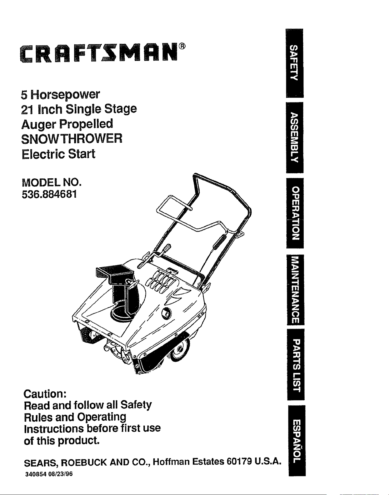
5 Horsepower
21 inch Single Stage
Auger Propelled
SNOWTHROWER
Electric Start
MODEL NO.
536.884681
Caution:
Read and follow all Safety
Rules and Operating
Instructions before first use
of this product.
SEARS, ROEBUCK AND CO., Hoffman Estates 60179 U.S.A.
340854 08/23/96
Table of Contents 2
Warranty 2
Safety Rules 2-4
Contents of Shipping Carton 4
Assembly 5
Operation 6-10
Maintenance 11
Service and Adjustments 12-15
Storage 16
Troubleshooting !7
Edger Repair Parts 18-24
Engine Repair Parts 25-28
Spanish (EspaSol) 29-45
Parts OrderinglService Back Cover
LIMITED TWO-YEAR WARRANT"( ON CRAFTSMAN SNOW THROWER
For two year from the date of purchase, when this Craftsman Snow Thrower is main-
tained, lubricated, and tuned up according to the operating and maintenance instruc-
tions in the owner's manual, Sears will repair, free of charge, any defect in material or
workmanship.
If this Craftsman Snow Thrower is used for commercial or rentat purposes, this war-
ranty applies for only 90 days from the date of purchase.
This warranty does not cover the following:
° Items which become worn during normal use, such as spark plugs, drive belts and
shear pins.
° Repairs necessary because of operator abuse or negligence, including bent crank
shafts and the failure to maintain the equipment according to the instructions con-
tained in the owner's manual
WARRAN'P{ SERVICE IS AVAILABLE BY RETURNING THE CRAFTSMAN SNOW
THROWER 1"OTHE NEAREST SEARS SERVICE CENTER/DEPARTMENT IN THE
UNITED STATES. THIS WARRANTY APPLIES ONLY WHILE THIS PRODUCT IS IN
USE IN THE UNITED STATES.
This warranty gives you specific legal rights, and you may also have other rights which
may vary from state to state.
Sears, Roebuck and Co D817WA Hoffrnan Estates IL 60179
Look for this symbol to point out important safety precautions, it means--
ATTENTION!!! Become alert!!t Your safety is involved.
_ CAUTION: Turn key to OFF position
and remove key to prevent accidental
starting when setting-up, transporting,
adjusting or making repairs.
IMPORTANT: Safety standards require
operator presence controls to minimize the "
risk of injury. '(our snow thrower is
equipped with such controls. Do not attempt
to defeat the function of the operator
presence control under any circumstances.
BEFORE USE
, Read the owner's manual carefully. Be
thoroughly familiar with the controls and
the proper use of the snow thrower. Know
how to stop the snow thrower and
disengage the controls quickly.
° Do not operate the snow thrower without
wearing adequate outer garments. Wear
footwear that will improve footing on
slippery surfaces.
Keep the area of operation clear of all
persons, particularly smatl children and
pets.
Thoroughly inspect the area where the
snow thrower is to be used and remove
all foreign objects.
Use extension cords and receptacles as
specified by the manufacturer for all snow
throwers with electric drive motors or with
factory-installed or optional starting
motors.
- Use only attachments and accessories
approved by the manufacturer of the
snow thrower (such as electric starter kits,
etc.).
• Never operate the snow thrower without
good visibility or light. Always be sure of
your footing, and keep a firm hold on the
handles. Walk; never run.
• This snow thrower is for use on side-
walks, driveways, and other ground level
surfaces. CAUTION: should be exercised
while using on steep sloping surfaces. DO
NOT USE SNOW THROWER ON
SURFACES ABOVE GROUND LEVEL
such as roofs of residences, garages,
porches or other such structures or
buildings.
• Check all bo_s at frequent intervals for
proper tightness to be sure the snow
thrower is in safe working condition_
• Disengage clutch before starting the
engine.
• Let engine and snow thrower adjust to
outdoor temperatures before starting to
clear snow.
FUEL SAFETY
° Handle fuel with care; it is highly flam.
mableo
- Use an approved container.
• Check fuel supply before each use,
allowing space for expansion as the heat
of the engine and/or sun can cause fuel
to expand.
• Fill fuel tank outdoors with extreme care.
Never fill fuel tank indoors. Replace fuel
tank cap securely and wipe up spilled
fuel.
• Never remove the fuel tank cap or add
fuel to a running or hot engine.
• Never store fuel or snow thrower with fuel
in the tank inside a building where fumes
may reach an open flame.
OPERATING SAFETY
• Never allow children or young teenagers
to operate the snow thrower, Keep them
away while it is operating° Never allow
adults to operate the snow thrower
without proper instruction.
• Do not operate this machine if you are
taking drugs or other medication which
can cause drowsiness or affect your
ability to operate this machine.
• Do not use this machine if you are
mentally or physically unable to operate
this machine safely,
• Always wear safety glasses or eye
shields during operation or while perform=
ing an adjustment or repair to protect
your eyes from foreign objects that may
be thrown from the snow thrower,
• Do not put hands or feet near or under
rotating parts. Keep clear of the discharge
opening at all times.
• Exercise extreme caution to avoid
slipping or falling, especially when
operating in reverse or backing up.
• Do not clear snow across the face of
slopes. Exercise caution when changing
direction on slopes. Do not attempt to
clear steep slopes.
, Never operate the snow thrower without
proper guards, plates, or other safety
protective devices in place_
, Never operate the snow thrower near
glass enclosures, automobiles, window
wells, drop-offs, and the like without
proper adjustment of the snow discharge
angle. Keep children and pets away.
° Never operate the snow thrower at high
transport speeds on slippery surfaces.
Look behind and use care when backing.
° Never direct discharge at bystanders or
allow anyone in front of the snow thrower°
• Do not run the engine indoors, except
when starting the engine and for trans-
porting the snow thrower in or out of the
building° Open the outside doors; exhaust
fumes are dangerous, containing CAR-
BON MONOXIDE, an ODORLESS and
DEADLY GAS.
• Take all possible precautions when
leaving the snow thrower unattended.
Disengage the augedimpoller, stop
engine, and remove key.
, Do not overload the machine capacity by
attempting to clear snow at to_) fast a rate.
SAFE STORAGE
° Always refer to the owner's manual
instructions for important details if the
snow thrower is to be stored for an
extended period.
• Disengage power to the auger/impeller
when snow thrower is transported or not
in use.
• Never store the snow thrower with fuel in
the fuel tank inside a building where
ignition sources are present such as
water and space heaters, clothes dryers,
and the like. Atlow the engine to cool
before storing in any enclosure.
REPAIR!ADJUSTMENTS SAFETY
• After striking a foreign object, stop the
engine (motor).. Turn the ignition OFF to
prevent accidental starting. Thoroughly
inspect the snow thrower for any damage,
and repair the damage before restarting
and operating ito
- If snow thrower should start to vibrate
abnormally, stop engine (motor) and
check immediately for the cause. Vibra-
tion is generally a warning of trouble.
° Stop the engine (motor) whenever you
leave the operating position. Also, remove
the ignition key before unclogging the
auger!impeller housing or discharge
chute, and when making any repairs,
adjustments, or inspections.
o When cleaning, repairing, or inspecting,
make certain the auger/impeller and all
moving parts have stopped, Remove the
ignition key to prevent accidental starting.
° Never attempt to make any adjustments
while the engine is running except when
specifically recommended by the manu-
facturer.
° Maintain or replace safety and instruction
labels, as necessary.
• Run the snow thrower a few minutes after
throwing snow to prevent freeze-up of the
auger/impeller.
/!_ WARNING: Th_ engine exhaust
from this product contains chemicals
known to the State of California to cause
cancer, birth defects or other reproductive
harm.
Z_ WARNING: This unit is equipped with
an internal combustion engine and should
not be used on or near any unimproved for-
est-covered, brush-covered or grass-cov-
ered land unless the engine's exhaust sys-
tem is equipped with a spark arrester meet-
ing applicable local or state laws (if any). tf a
spark arrester is used, it should be main-
tained in effective working order by the op-
erator.
In the state of California the spark arrester is
required by law (Section 4442 of the Califor-
nia Public Resources Code). Other states
may have similar laws. Federal laws apply
on federal lands. A spark attester/muffler is
available through your nearest Sears Autho-
rized Service Center (See ENGINE REPAIR
PARTS section in this manual).
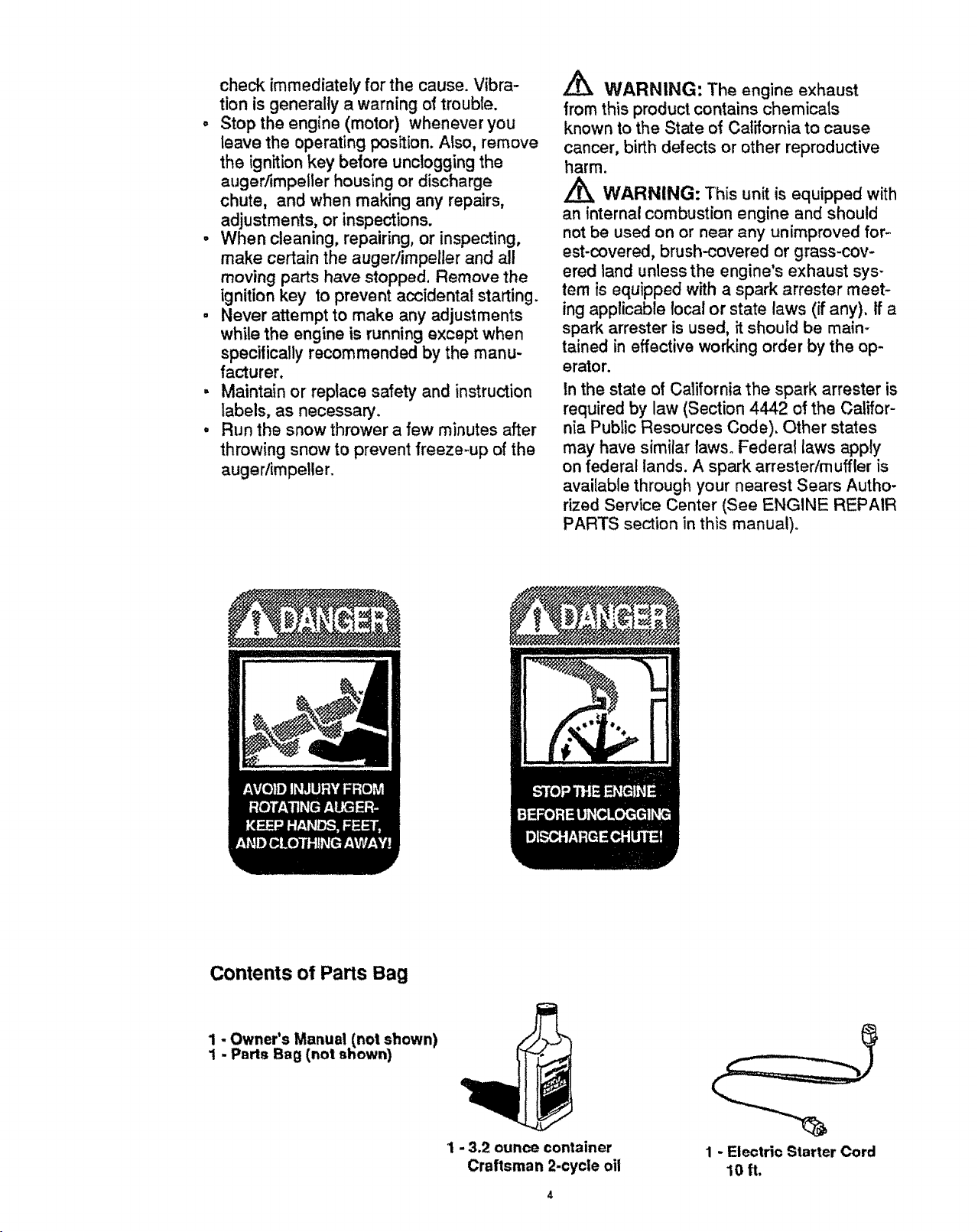
Contents of Parts Bag
1 - Owner's Manual (not shown)
1 - Parts Bag (not shown)
1 - 3.2 ounce container
Craftsman 2-cycle oil
1 - Electric Starter Cord
10ft.
,&
LL&CAUTION: Always wear safety
glasses or eye shields while assembling
snow thrower.
TOOLS REQUIRED FOR ASSEMBLY
1 - Knife to cut carton
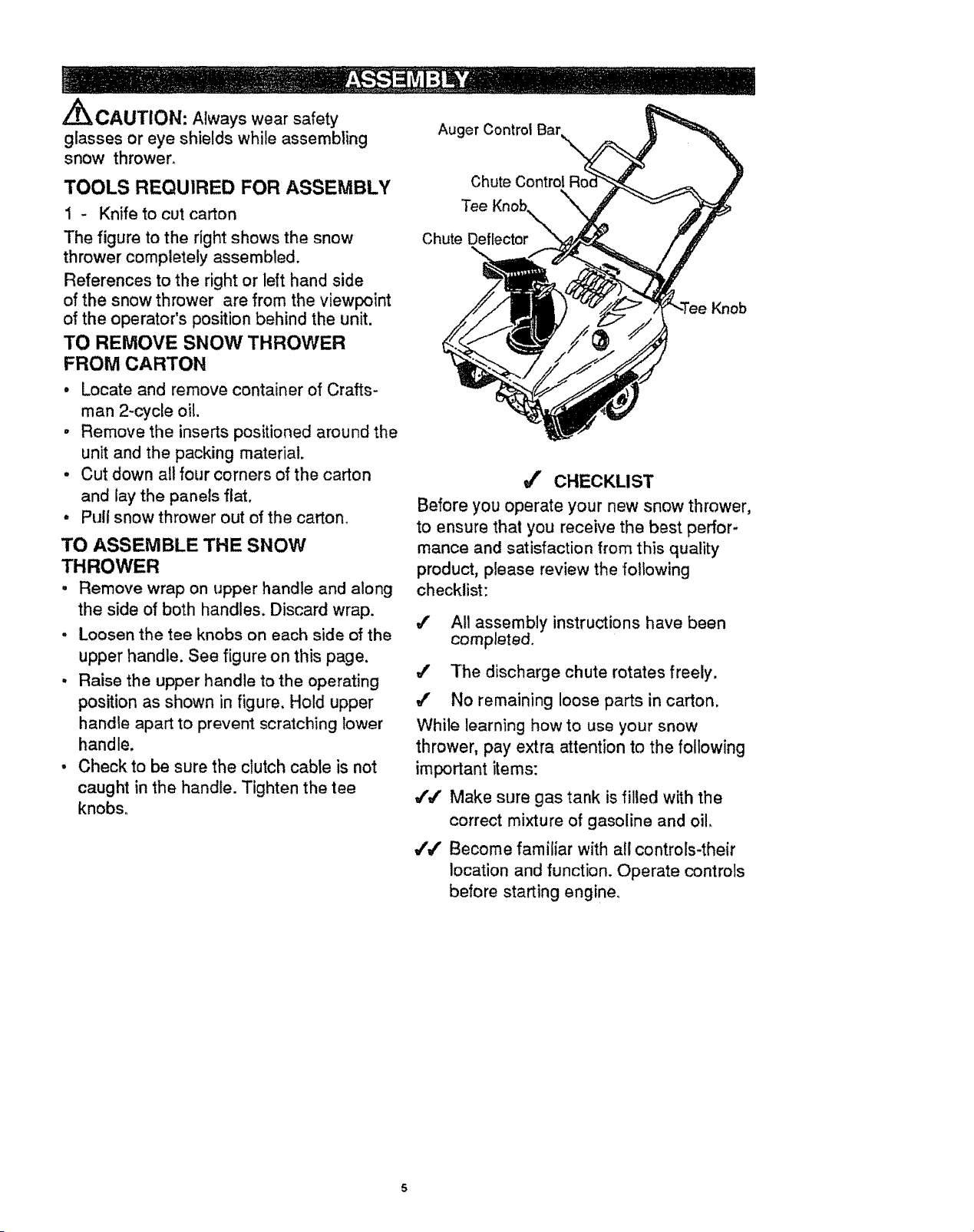
The figure to the right shows the snow
thrower completely assembled.
References to the right or left hand side
of the snow thrower are from the viewpoint
of the operator's position behind the unit.
TO REMOVE SNOW THROWER
FROM CARTON
• Locate and remove container of Crafts-
man 2-cycle oil.
• Remove the inserts positioned around the
unit and the packing material.
, Cut down all four corners of the carton
and lay the panels flat.
• Pull snow thrower out of the carton.
TO ASSEMBLE THE SNOW
THROWER
• Remove wrap on upper handle and along
the side of both handles. Discard wrap.
, Loosen the tee knobs on each side of the
upper handle. See figure on this page.
, Raise the upper handle to the operating
position as shown in figure. Hold upper
handle apart to prevent scratching lower
handle.
• Check to be sure the clutch cable is not
caught in the handle. Tighten the tee
knobs.
Auger Control Bar
Chute Control Roc
Knob
TeeKnob,
Chute Deflecto______
,/' CHECKLIST
Before you operate your new snow thrower,
to ensure that you receive the best perfor-
mance and satisfaction from this quality
product, please review the following
checklist:
4' All assembly instructions have been
completed.
,/' The discharge chute rotates freely.
#" No remaining loose parts in carton.
While learning how to use your snow
thrower, pay extra attention to the following
important items:
,(,/' Make sure gas tank is filled with the
correct mixture of gasoline and oil.
#'_ Become familiar with all controls-their
location and function. Operate controls
before starting engine°
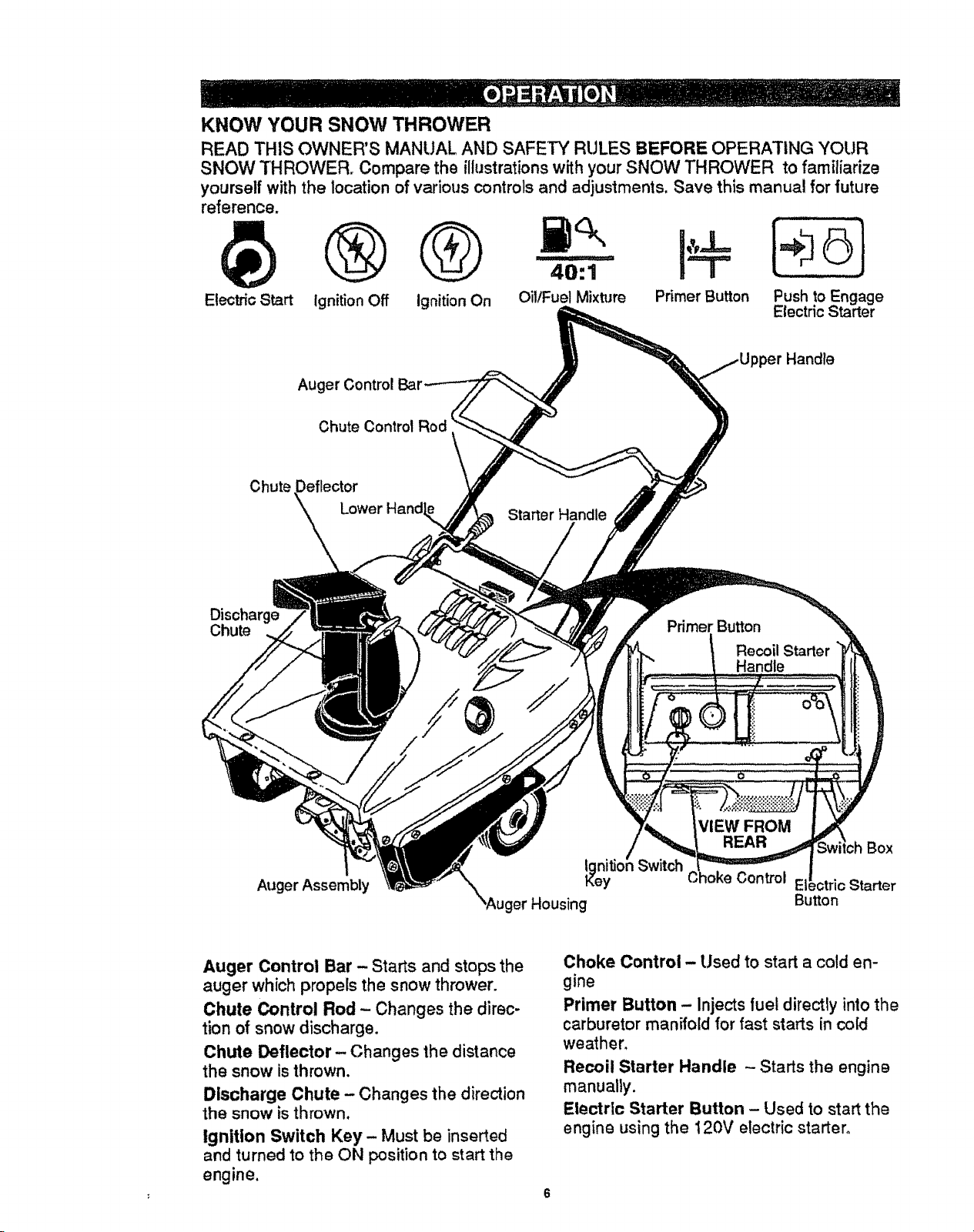
KNOW YOUR SNOW THROWER
READ THIS OWNER'S MANUAL AND SAFETY RULES BEFORE OPERATING YOUR
SNOW THROWER. Compare the illustrations with your SNOW THROWER to familiarize
yourself with the location of various controls and adjustments. Save this manual for future
reference.
Electric Start Ignition Off Ignition On OillFuel Mixture Primer Button Push to Engage
Electric Starter
Auger Control
Chute Control Rod
Handle
Chute Deflector
\_X \ Lower Hand<
Starter Handle
Dis_
Chute
Primer Button
Recoil Starter
Handle
Auger Assembly
ger Housing
VIEW FROM
REAR
Box
Control El ,=¢tricStarter
Button
Auger Control Bar - Starts and stops the
auger which propels the snow thrower.
Chute Control Rod - Changes the direc-
tion of snow discharge.
Chute Deflector- Changes the distance
the snow is thrown.
Discharge Chute - Changes the direction
the snow is thrown.
Ignition Switch Key- Must be inserted
and turned to the ON position to start the
engine.
Choke Control - Used to start a cold en-
gine
Primer Button - Injects fuel directly into the
carburetor manifold for fast starts in cold
weather.
Recoil Starter Handle - Starts the engine
manually.
Electric Starter Button - Used to start the
engine using the t20V electric starter.
HOW TO USE YOUR
SNOW THROWER
TO STOP YOUR SNOW THROWER
• To stop the auger, release the auger
control barn
NOTE: if the auger continues to creep, refer
(To Adjust Auger Control Cable paragraph on
page 12).
o To stop the engine, turn key to the OFF
position.
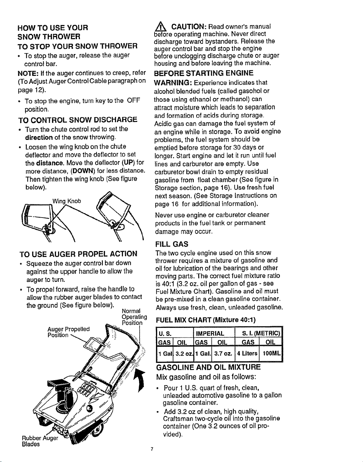
TO CONTROL SNOW DISCHARGE
. Turn the chute control rod to set the
direction of the snow throwing.
• Loosen the wing knob on the chute
deflector and move the deflector to set
the distance. Move the deflector (UP) for
more distance, (DOWN) for tess distance.
Then tighten the wing knob (See figure
be!ow)_
WiF
TO USE AUGER PROPEL ACTION
, Squeeze the auger control bar down
against the upper handle to al!ow the
auger to turn.
• To propel forward, raise the handle to
allow the rubber auger blades to contact
the ground (See figure below).
Normal
Operating
Pos
Auger Propelled
Position
Rubber
Blades
,_ CAUTION: Read owner's manual
before operating machine. Never direct
discharge toward bystanders_ Release the
auger control bar and stop the engine
before unclogging discharge chute or auger
housing and before leaving the machine.
BEFORE STARTING ENGINE
WARNING; Experience indicates that
alcohol blended fuels (called gasohol or
those using ethanol or methanol) can
attract moisture which leads to separation
and formation of acids during storage.
Acidic gas can damage the fuel system of
an engine while in storage. To avoid engine
problems, the fuel system should be
emptied before storage for 30 days or
longer. Start engine and let it run until fuel
lines and carburetor are empty. Use
carburetor bowl drain to empty residual
gasoline from float chamber (See figure in
Storage section, page 16). Use fresh fuel
next season, (See Storage Instructions on
page t6 for additional information).
Never use engine or carburetor cleaner
products in the fuel tank or permanent
damage may occur.
FILL GAS
The two cycle engine used on this snow
thrower requires a mixture of gasoline and
oil for lubrication of the bearings and other
moving parts. The correct fuel mixture ratio
is 40:1 (3.2 oz. oil per gallon of gas - see
Fuel Mixture Chart). Gasoline and oil must
be pre-mixed in a clean gasoline container,
Always use fresh, clean, unleaded gasoline.
:UEL MIX CHART (Mixture 40:1)
, i ,,,
U.S. IMPERIAL S.I. (METRIC)
GAS OIL GAS OIL GAS OIL
1 Gal 3.2 oz, 1 Gal, 3.7 oz. 4 Liters 100ML
GASOLINE AND OIL MIXTURE
Mix gasoline and oil as follows:
Pour 1 U°S. quart of fresh, clean,
unleaded automotive gasoline to a gallon
gasoline container.
Add 3.2 oz of clean, high quality,
Craftsman two-cycle oil into the gasoline
container (One 3,2 ounces of oil pro-
vided).
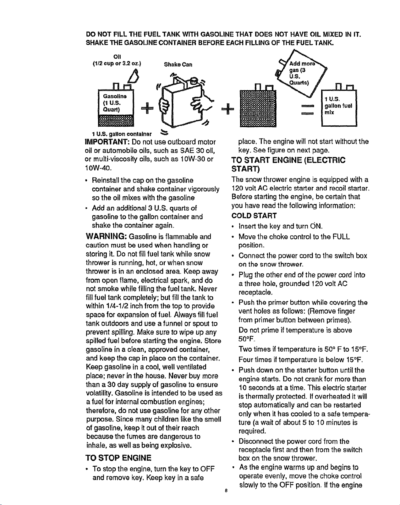
DO NOT FILL THE FUEL TANK WITH GASOLINE THAT DOES NOT HAVE OIL MIXED IN IT.
SHAKE THE GASOLINE CONTAINER BEFORE EACH FILLING OF THE FUEL TANK.
O11
(1/2 cup or 3.2 ozo) Shake Can
O'
(1u.s. ! l
1 U.S. gallon container
IMPORTANT: Do not use outboard motor
oil or automobile oils, such as SAE 30 oil,
or multi-viscosity oils, such as 10W-30 or
10W-40.
• Reinstall the cap on the gasoline
container and shake container vigorously
so the oil mixes with the gasoline
, Add an additional 3 U.S. quarts of
gasoline to the gallon container and
shake the container again.
WARNING: Gasoline is flammable and
caution must be used when handling or
storing it. Do not fill fuel tank while snow
thrower is running, hot, or when snow
thrower is in an enclosed area. Keep away
from open flame, electrical spark, and do
not smoke while filling the fuel tank. Never
fill fuel tank completely; but fill the tank to
within 1t4-1/2 inch from the top to provide
space for expansion of fue!. Always fill fuel
tank outdoors and use a funnel or spout to
prevent spilling. Make sure to wipe up any
spilled fuel before starting the engine. Store
gasoline in a clean, approved container,
and keep the cap in place on the container.
Keep gasoline in a cool, well ventilated
place; never in the house. Never buy more
than a 30 day supply of gasoline to ensure
volatility. Gasoline is intended to be used as
a fuel for internal combustion engines;
therefore, do not use gasoline for any other
purpose. Since many children like the smell
of gasoline, keep it out of their reach
because the fumes are dangerous to
inhale, as well as being explosive.
TO STOP ENGINE
• To stop the engine, turn the key to OFF
and remove key. Keep key in a safe
+
place. The engine will not start without the
key. See figure on next page.
TO START ENGINE (ELECTRIC
START)
The snow thrower engine is equipped with a
120 volt AC electric starter and recoil starter.
Before starting the engine, be certain that
you have read the following information:
COLD START
• Insert the key and turn (JNo
• Move the choke control to the FULL
positiom
• Connect the power cord to the switch box
on the snow thrower.
• Plug the other end of the power cord into
a three hole, grounded 120 volt AC
receptacle.
- Push the primer button while covering the
vent holes as follows: (Remove finger
from primer button between primes).
Do not prime if temperature is above
50°F
Two times if temperature is 50 ° F to 15°F.
Four times if temperature is below 15°F.
• Push down on the starter button until the
engine starts. Do not crank for more than
10 seconds at a time° This efectric starter
is thermally protected If overheated it will
stop automatically and can be restarted
only when it has cooled to a safe tempera.
ture (a wait of about 5 to 10 minutes is
required.
• Disconnect the power cord from the
receptacle first and then from the switch
box on the snow thrower.
• As the engine warms up and begins to
operate evenly, move the choke control
slowly to the OFF position, if the engine
falters, returnto 1/2chokeuntilit runs
smoothly, then move to OFF position,
NOTE: Allow engine to warm up for a
few minutes before using snow thrower,
as the engine will not develop full power
until it reaches operating temperature.
WARM START
Be sure the choke is in the OFF posio
tion and pull the starter handle until the
engine starts.
Do not prime a warm engine. If the en-
gine fails to start, follow the Cold En-
gine Start instructions on page 8.
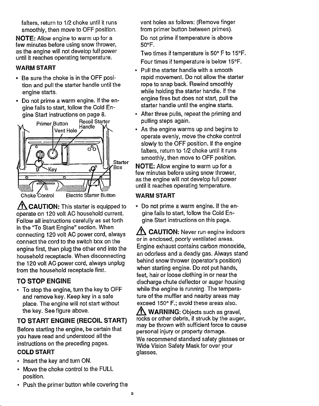
Primer Button Recoil Starter
Handle
Vent Hole
Starter
Choke' Electric Button
/_ CAUTION: This starter is equipped to
operate on 120 volt AC household current.
Follow all instructions carefully as set forth
in the "To Start Engine" section. When
connecting 120 volt AC power cord, always
connect the cord to the switch box on the
engine first, then plug the other end into the
household receptacle. When disconnecting
the 120 volt AC power cord, always unplug
from the household receptacle first.
TO STOP ENGINE
, To stop the engine, turn the key to OFF
and remove key° Keep key in a safe
place° The engine will not start without
the key. See figure above.
TO START ENGINE (RECOIL START)
Before starting the engine, be certain that
you have read and understood all the
instructions on the preceding pages°
COLD START
, Insert the key and turn ON.
• Move the choke control to the FULL
position.
, Push the primer button while covering the
vent holes as follows: (Remove finger
from primer button between primes).
Do not prime if temperature is above
50°F.
Two times if temperature is 50° F to 15°F.
Four times if temperature is below 15°F.
, Pull the starter handle with a smooth
rapid movement. Do not allow the starter
rope to snap back. Rewind smoothly
while holding the starter handle. If the
engine fires but does not start, pull the
starter handle until the engine starts.
, After three pulls, repeat the priming and
pulling steps again.
° As the engine warms up and begins to
operate evenly, move the choke control
slowly to the OFF position, If the engine
falters, return to 1/2 choke until it runs
smoothly, then move to OFF position.
NOTE: Allow engine to warm up for a
few minutes before using snow thrower,
as the engine will not develop full power
until it reaches operating temperature,
WARM START
o Do not prime a warm engine. If the en-
gine fails to start, follow the Cold En-
gine Start instructions on this page.
,_ CAUTION: Never run engine indoors
or in enclosed, poorly ventilated areas_
Engine exhaust contains carbon monoxide,
an odorless and a deadly gas. Always stand
behind snow thrower (operator's position)
when starting engine. Do not put hands,
feet, hair or loose clothing in or near the
discharge chute deflector or auger housing
while the engine is running The tempera-
ture of the muffler and nearby areas may
exceed 150 ° F.; avoid these areas also.
WARNING: Objects such as gravel,
rocks or other debris, if struck by the auger,
may be thrown with sufficient force to cause
personal injury or property damage.
We recommend standard safety glasses or
Wide Vision Safety Mask for over your
glasses.
SNOW THROWING TIPS
, This snow thrower will propel itself
for._ard when the handle is raised
enough to cause the auger blades to
contact the ground. The auger should
stop when auger control bar is released.
If it does not, refer to Adjust Auger
Control Cable paragraph on page !2.
• For most efficient snow throwing, turn the
discharge chute deflector to throw snow
downwind, and slightly overlap each
swath. In light snow take up to a full cut
and in heavy snow take less than a full
cut.
o The distance snow will be discharged can
be adjusted by moving the discharge
chute deflector. Raise the deflector for
more distance or lower the deflector for
less distance.
• In windy conditions, lower the chute
deflector to direct discharged snow close
to the ground where it is less likely to
blow into unwanted areas.
o Keep the area to be cleared free of
stones, toys and other foreign objects for
safety and to prevent damage to the
snow thrower.
Do not use the auger propelling feature
when clearing gravel or crushed rock
driveways. Move the handle down to
raise the auger slightly.
The allowable forward speed of the snow
thrower is dependent on the depth and
weight of the snow. Experience wilt
establish the most effective method of
using the snow thrower under different
conditions.
DRY AND AVERAGE SNOW
• Snow up to eight inch depth can be
removed rapidly and easily by walking at
a moderate rate. For snow or drifts of a
greater depth you may find it desirable to
slow your pace to allow the discharge
chute to dispose of the snow as rapidly
as the auger receives the snow.
• Plan to have the snow discharged in the
direction the wind is blowing_
WET PACKED SNOW
• Move slowly into snow of this condition.
Thegreaterthe depth,the sloweryou
should go. When it appears that the wet,
packed snow is causing the auger to slow
down and the chute to clog, back off and
begin a series of short jabs into the snow,
These short back and forth, 4 to 6 inch,
jabbing motions wilt "belch" the snow
from the chute°
SNOW BANKS AND DRIFTS
• In snow of greater depth than the unit,
use the jabbing technique described
above. Turn the discharge chute away
from the snow bank. More time will be
required to remove snow of this type than
level snow.
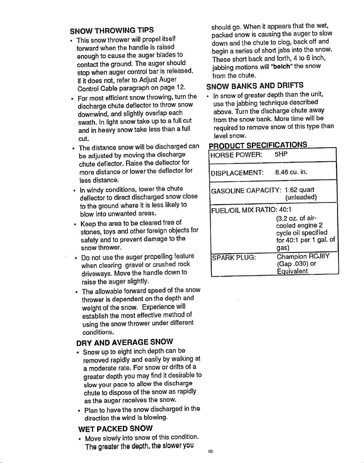
PRODUCT SPECIFICATIONS
HORSE POWER: 5HP
DISPLACEMENT: 8.46 cue in.
GASOLINE CAPACITY: 1_62 quart
(unleaded)
FUEL/OIL MIX RATIO: 40:1
SPARK PLUG:
(3.2 oz. of air-
cooled engine 2
cycle oil specified
for40:1 per 1 gal. of
gas)
Champion RCJSY
(Gap .030) or
Equivalent
!o
SERVICE
RECORDS
Fill In dates as
you complete
regular service
TighienAllScrews & Nuts
Check SparkPlug
1
check Drive Belts
LUbricateChuteControtRange
,,,,,L
Check Fuel
,,,,...... ,,Jr ,,,,
Drain Fue!
Before
Each
Use
After
first 12
Hours
SCHEDULE
As Before
Needed Storage
v"
v"
Begin
Each
Season
SERVICE
DATES
GENERAL RECOMMENDATIONS
The warranty on this snow thrower does not
cover items that have been subjected to op-
erator abuse or negligence. To receive full
value from the warranty, the operator must
maintain the snow thrower as instructed in
this manual. The above chart is provided to
assist the operator in properly maintaining
the snow thrower.
LU BRICATION CHART
SNOW THROWER
AFTER FIRST USE
o Check for any loose or damaged parts
after each use.
• Tighten any loose fasteners.
AFTER EACH USE
, Run the machine to clear the auger of
snow.
• Remove all snow and slush from the snow
thrower to prevent freezing of auger or
controls.
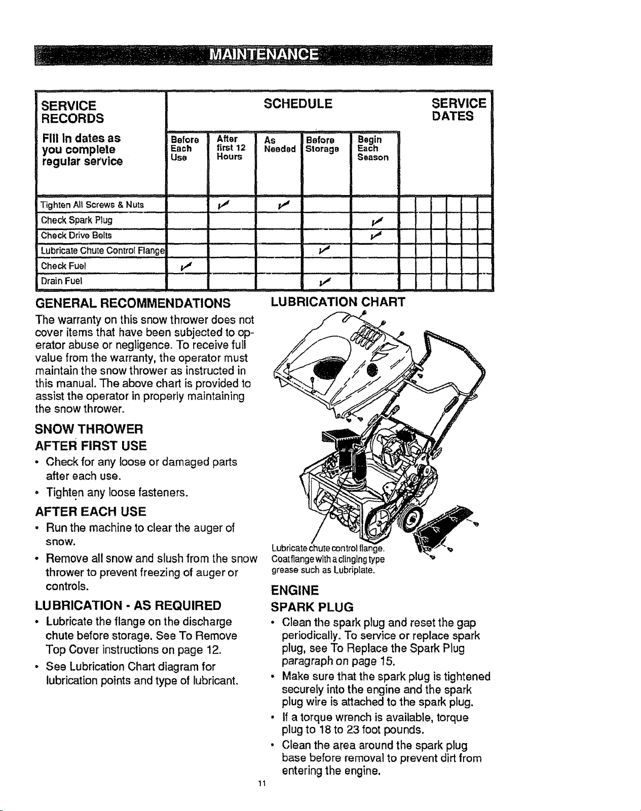
LUBRICATION - AS REQUIRED
. Lubricate the flange on the discharge
chute before storage, See To Remove
Top Cover instructionson page 12_
° See Lubrication Chart diagram for
lubrication points and type of lubricant.
1t
Lubricate chute controt flange,
Coatflange with aclingingtype
grease such as Lubriplate,,
ENGINE
SPARK PLUG
• Clean the spark plug and reset the gap
periodically. To service or replace spark
plug, see To Replace the Spark Plug
paragraph on page 15.
• Make sure that the spark plug is tightened
securely into the engine and the spark
plug wire is attached to the spark plug.
• If a torque wrench is available, torque
plug to 18 to 23 foot pounds.
• Clean the area around the spark plug
base before removal to prevent dirt from
entering the engine.
CARBURETOR ADJUSTMENT
The carburetor on this snow thrower is not
adjustable.
IMPORTANT: If you think the carburetor is
not operating properly, contact your
nearest Sears service center.
CAUTION: Never tamper with the
engine governor which is factory set for
proper engine speed. Over speeding the
engine may increase the danger of
personal injury and wilt void the engine
warranty. If you think the engine governor
high speed needs adjusting, contact your
nearest Sears service center who has the
proper equipment and experience to
make any unnecessary adjustments.
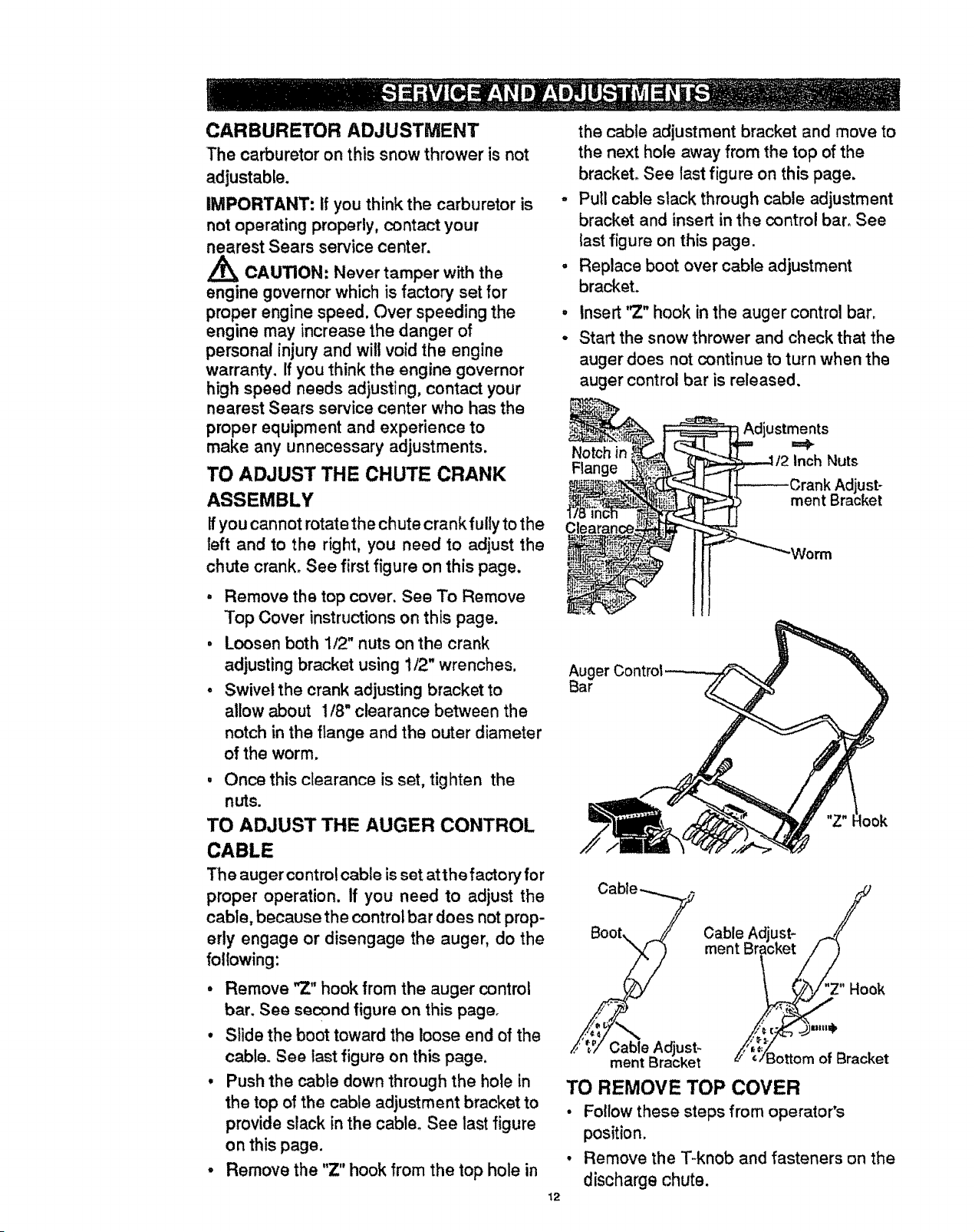
TO ADJUST THE CHUTE CRANK
ASSEMBLY
If you cannot rotate the chute crank fully to the
left and to the right, you need to adjust the
chute crank. See first figure on this page.
, Remove the top cover. See To Remove
Top Cover instructionson this page.
• Loosen both 1/2" nuts on the crank
adjusting bracket using 1/2" wrenches.
• Swivel the crank adjusting bracket to
allow about 1/8" clearance between the
notch in the flange and the outer diameter
of the worm.
, Once this clearance is set, tighten the
nuts.
TO ADJUST THE AUGER CONTROL
CABLE
The auger control cable is set at the factory for
proper operation. If you need to adjust the
cable, because the control bar does not prop-
erly engage or disengage the auger, do the
following:
• Remove "7." hook from the auger control
bar. See second figure on this pager
• Slide the boot toward the loose end of the
cable. See last figure on this page.
• Push the cable down through the hole in
the top of the cable adjustment bracket to
provide slack in the cable. See last figure
on this page.
• Remove the "Z" hook from the top hole in
t2
the cable adjustment bracket and move to
the next hole away from the top of the
bracket, See last figure on this page,
- Pull cable slack through cable adjustment
bracket and insert in the control bar° See
last figure on this page.
• Replace boot over cable adjustment
bracket.
• Insert '_" hook in the auger control bar.
° Start the snow thrower and check that the
auger does not continue to turn when the
auger control bar is released,
Adjustments
Notch in ==_
Fl_'lge Inch Nuts
Ctearan
Auger
Bar
look
Cable Adjust_
ment Bracket
Cable Adlust- /
ment Br'lcket!//)
Z" Hook
_'/ =/i3ottom of Bracket
TO REMOVE TOP COVER
• Follow these steps from operator's
position.
, Remove the T-knob and fasteners on the
discharge chute.
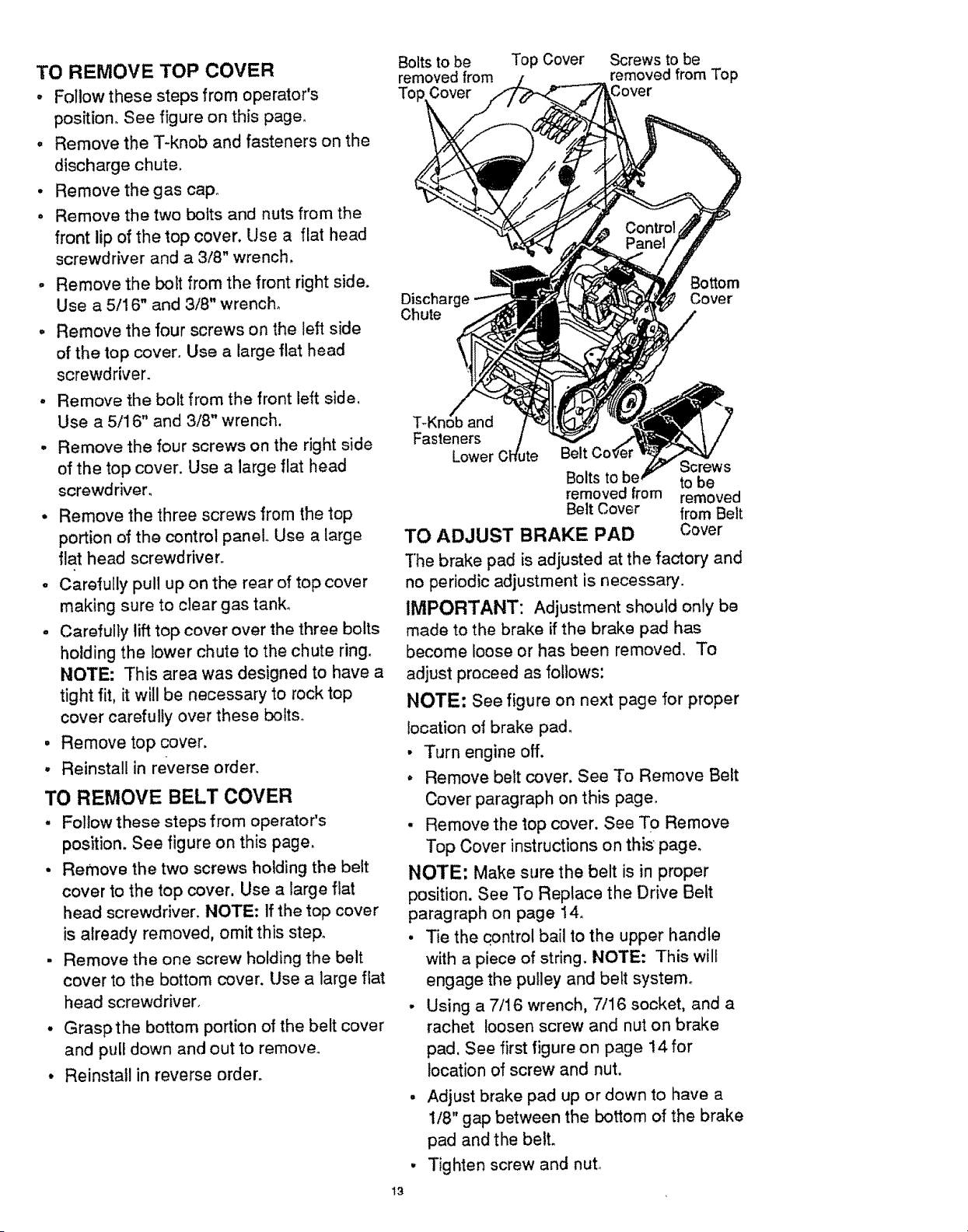
TO REMOVE TOP COVER
- Follow these steps from operator's
position. See figure on this page
• Remove the T-knob and fasteners on the
discharge chute
• Remove the gas cap
o Remove the two bolts and nuts from the
front lip of the top cover. Use a flat head
screwdriver and a 3/8" wrench,
• Remove the bolt from the front right side.
Use a 5/16" and 3/8" wrench,
, Remove the four screws on the left side
of the lop cover° Use a large flat head
screwdriver.
° Remove the bolt from the front left side,
Use a 5/16" and 3/8" wrench.
• Remove the four screws on the right side
of the top cover Use a large flat head
screwdriven
° Remove the three screws from the top
portion of the control panel° Use a large
flat head screwdriver
- Carefully pull up on the rear of top cover
making sure to clear gas tank_
° Carefully lift top cover over the three bolts
holding the lower chute to the chute ring
NOTE: This area was designed to have a
tight fit, it will be necessary to rock top
cover carefully over these bolts°
. Remove top cover
° Reinstall in reverse order
TO REMOVE BELT COVER
- Follow these steps from operator's
position. See figure on this page,
° Remove the two screws holding the belt
cover to the top cover, Use a large flat
head screwdriver. NOTE: If the top cover
is already removed, omit this step.
- Remove the one screw holding the belt
cover to the bottom cover. Use a large flat
head screwdriver.
. Graspthe bottom portion of the belt cover
and pull down and out to remove.
° Reinstall in reverse order.
13
Bolts to be Top Cover Screws to be
removed from removed from Top
Top Cover
Discharge
Chute
Bottom
Cover
T_Kn
Fasteners
Lower
Belt
Screws
Bolts to to be
removed from removed
Belt Cover from Belt
Cover
TO ADJUST BRAKE PAD
"[he brake pad is adjusted at the factory and
no periodic adjustment is necessary
IMPORTANT: Adjustment should only be
made to the brake if the brake pad has
become loose or has been removed To
adjust proceed as follows:
NOTE: See figure on next page for proper
location of brake pad.
• Turn engine off
. Remove belt cover. See To Remove Belt
Cover paragraph on this page
• Remove the top cover. See To Remove
Top Cover instructions on this page
NOTE: Make sure the belt is in proper
position. See To Replace the Drive Belt
paragraph on page 14
• Tie the qontrol bail to the upper handle
with a piece of string NOTE: This will
engage the pulley and belt system_
- Using a 7/16 wrench, 7/16 socket, and a
rachet loosen screw and nut on brake
pad See first figure on page 14 for
location of screw and nut
. Adjust brake pad up or down to have a
1/8" gap between the bottom of the brake
pad and the belt
• Tighten screw and nut
IdlerPulley
Screw and nut to
be loosened Pulley
Brake Pad
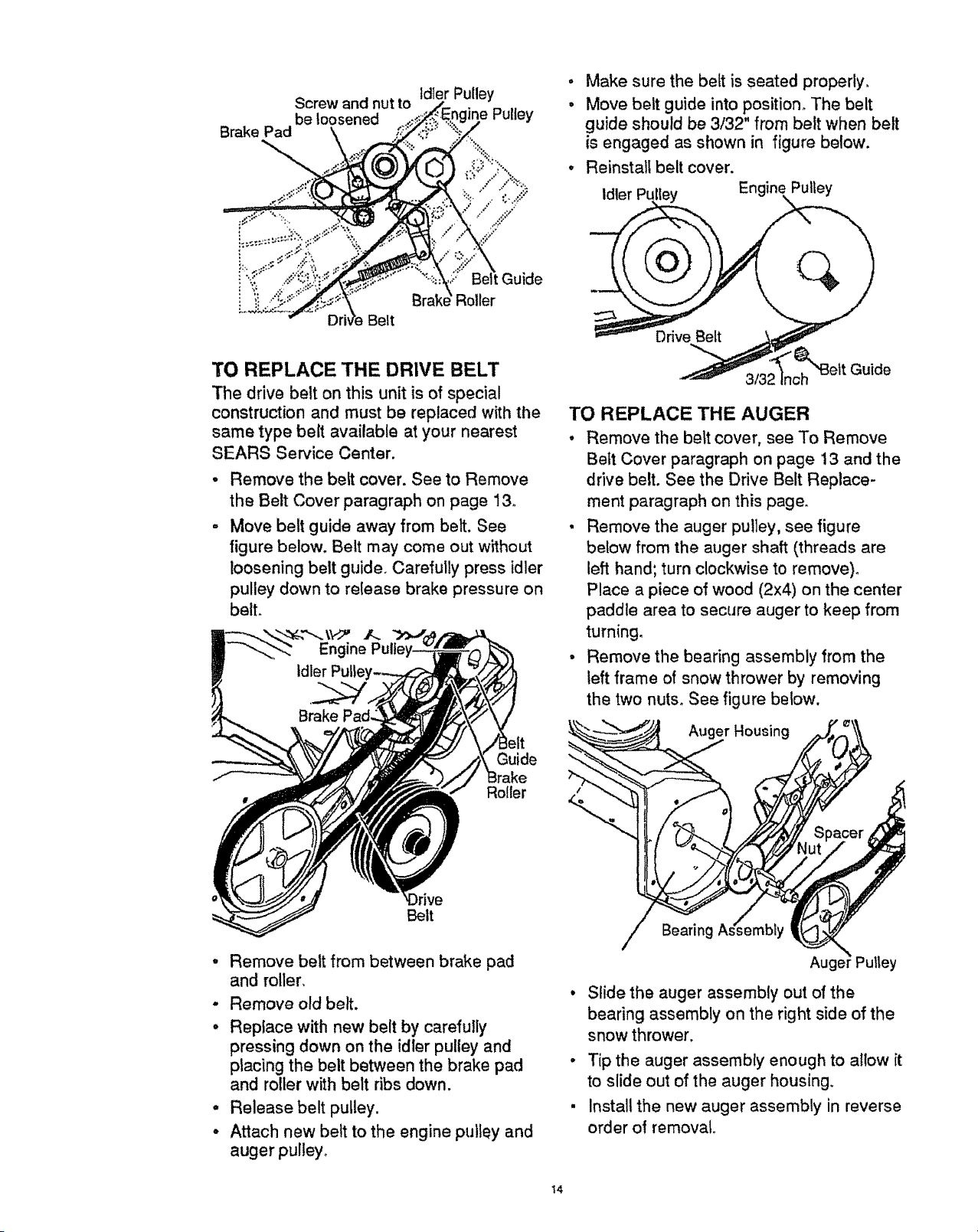
- Make sure the belt is seated properly.
• Move belt guide into position. The belt
guide should be 3/32" from belt when belt
is engaged as shown in figure below.
• Reinstalt belt cover.
Idler PuIley Engine Pulley
Belt
Roller
TO REPLACE THE DRIVE BELT
The drive belt on this unit is of special
construction and must be replaced with the
same type belt available at your nearest
SEARS Service Center.
Remove the belt cover. See to Remove
the Belt Cover paragraph on page 13.
Move belt guide away from belt. See
figure below. Belt may come out without
loosening belt guide. Carefully press idler
pulley down to release brake pressure on
belt.
Guide
Roller
Belt
o
o
o
o
Remove belt from between brake pad
and roller,
Remove old belt.
Replace with new belt by carefully
pressing down on the idler pulley and
placing the belt between the brake pad
and roller with belt ribs down.
Release belt pulley.
Attach new belt to the engine pulley and
auger pulley_
Guide
TO REPLACE THE AUGER
• Remove the belt cover, see To Remove
Bett Cover paragraph on page 13 and the
drive belt. See the Drive Belt Replace-
ment paragraph on this page.
• Remove the auger pu!ley, see figure
below from the auger shaft (threads are
left hand; turn clockwise to remove)°
Place a piece of wood (2x4) on the center
paddle area to secure auger to keep from
turning.
• Remove the bearing assembly from the
left frame of snow thrower by removing
the two nuts. See figure below.
__w_w_ Auger Hous,ng ,_
Spacer
1!l'!
uger utley
• Slide the auger assembly out of the
bearing assembly on the right side of the
snow thrower.
o Tip the auger assembly enough to allow it
to slide out of the auger housing.
. Install the new auger assembly in reverse
order of removal.
14
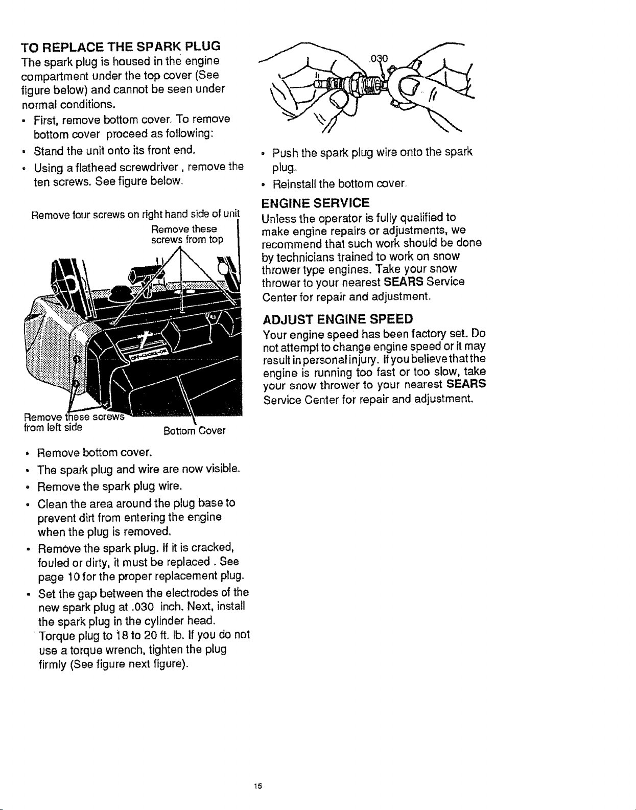
TO REPLACE THE SPARK PLUG
The spark plug is housed in the engine
compartment under the top cover (See
figure below) and cannot be seen under
normal conditions.
• First, remove bottom cover° To remove
bottom cover proceed as following:
. Stand the unit onto its front end.
, Using a flathead screwdriver, remove the
ten screws. See figure below_
Remove four screws on right hand side of unit
Remove these
screws from top
Remove lese screw
from left side
Bottom Cover
, Remove bottom cover.
• The spark plug and wire are now visible.
• Remove the spark plug wire.
• Clean the area around the plug base to
prevent dirt from entering the engine
when the plug is removed.
• Remove the spark plug. If it is cracked,
fouled or dirty, it must be replaced _See
page 10 for the proper replacement plug.
- Set the gap between the electrodes of the
new spark plug at .030 inch. Next, install
the spark plug in the cylinder head.
Torque plug to 18 to 20 ft. lb. if you do not
use a torque wrench, tighten the plug
firmly (See figure next figure).
. Push the spark plug wire onto the spark
plugo
• Reinstall the bottom cover
ENGINE SERVICE
Unless the operator is fully qualified to
make engine repairs or adjustments, we
recommend that such work should be done
by technicians trained to work on snow
thrower type engines. Take your snow
thrower to your nearest SEARS Service
Center for repair and adjustment,
ADJUST ENGINE SPEED
Your engine speed has been factory set. Do
not attempt to change engine speed or it may
result inpersonal injury. Ifyou believe that the
engine is running too fast or too slow, take
your snow thrower to your nearest SEARS
Service Center for repair and adjustment.
13
WARNING: Never store your snow
thrower indoors or in an enclosed, poorly
ventilated area. If gasoline remains in the
tank, fumes may reach an open flame,
spark or pilot light from a furnace, water
heater, clothes dryer, cigarette, etc.
To prevent engine damage (if snow thrower
is not used for more than 30 days) follow
the steps below.
SNOW THROWER STORAGE
- Thoroughly clean the snow thrower.
• Lubricate all the lubrication points.. See
the Maintenance section, page 11.
° Be sure that all nuts, bolts and screws are
securely fastened. Inspect all visible
moving parts for damage, breakage and
wear. Replace if necessary.
- Touch up all rusted or chipped paint
surfaces; sand lightly before painting.
° Cover the bare metal parts of the blower
housing and auger with rust preventative,
such as a spray lubricant.
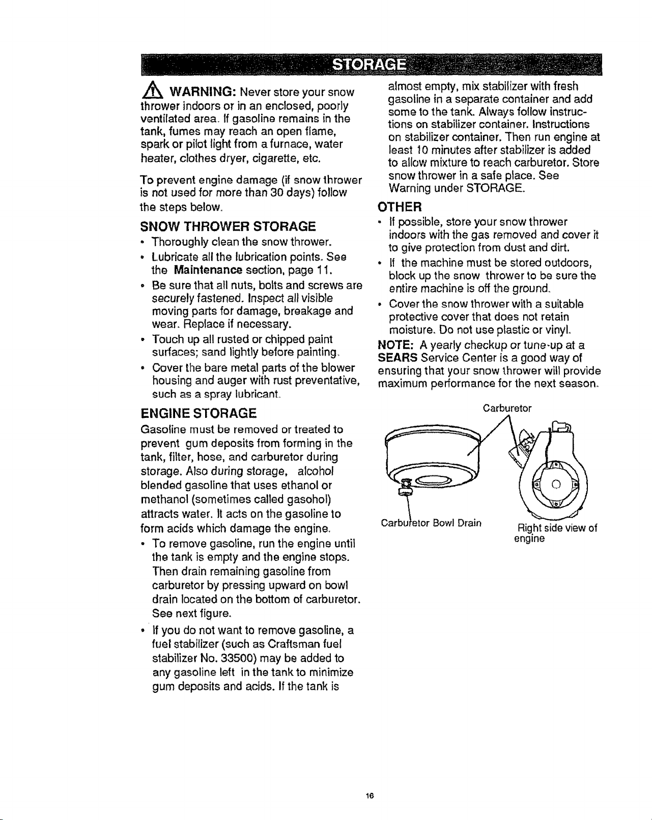
ENGINE STORAGE
Gasoline must be removed or treated to
prevent gum deposits from forming in the
tank, filter, hose, and carburetor during
storage. Also during storage, alcohol
blended gasoline that uses ethanol or
methanol (sometimes called gasohol)
attracts water. It acts on the gasoline to
form acids which damage the engine.
. To remove gasoline, run the engine until
the tank is empty and the engine stops.
Then drain remaining gasoline from
carburetor by pressing upward on bowl
drain located on the bottom of carburetor.
See next figure.
• If you do not want to remove gasoline, a
fuel stabilizer (such as Craftsman fuel
stabilizer No. 33500) may be added to
any gasoline left in the tank to minimize
gum deposits and acids. If the tank is
almost empty, mix stabilizer with fresh
gasoline in a separate container and add
some to the tank. Always follow instruc-
tions on stabilizer container. Instructions
on stabilizer container. Then run engine at
least 10 minutes after stabilizer is added
to allow mixture to reach carburetor. Store
snow thrower in a safe pface_ See
Warning under STORAGE.
OTHER
• if possible, store your snow thrower
indoors with the gas removed and cover it
to give protection from dust and dirt.
• If the machine must be stored outdoors,
block up the snow thrower to be sure the
entire machine is off the ground
, Cover the snow thrower with a suitable
protective cover that does not retain
moisture_ Do not use plastic or vinyl.
NOTE: A yearly checkup or tune-up at a
SEARS Service Center is a good way of
ensuring that your snow thrower will provide
maximum performance for the next season.
Carburetor
Garb! Bowl Drain
Rig.ht side view of
engine
16

TROUBLE
Difficult starting
Engine stalls
Engine runs er-
ratically
or
Loss of power
CAUSE
Defective spark plug
Unit running on CHOKE
Blocked fuel line or low on fuel
Water or dirt in fuel system
Carburetor out of adjustment
Excessive
vibration
Units fails to
propel itself
Unit fails to
discharge snow
Loose parts; damaged impeller
Damaged auger
Drive belt loose or damaged
Incorrect adjustment of auger con-
trol cable
Auger drive belt loose or damaged
Auger control cable not adjusted
correctly
Discharge chute clogged
Foreign object lodged in auger
CORRECTION
Replace defective plug
Move choke lever to OFF
position ....
Clean fuel line; check fuel sup-
ply; add fresh gasoline (gaso-
line!oil mixture if 2-cycle engine)
Use carburetor bowl drain to
flush and refill with fresh fuel
See carburetor adjustment
section in this manual
Stop engine immediately and
remove key, Tighten all bolts
and make all necessary repairs°
if vibration continues, have the
unit serviced by a Sears service
repairman
Repair or replace auger
assembly
Replace drive belt
Adjust auger control cable
Adjust auger drive belt; replace
if damaged
Adjust auger control cable
Stop engine immediately and re-
move key. Clean discharge
chute and inside of auger hous-
ing
Stop engine immediately and re-
move key° Remove object from
auger°
17
Items Su_
with motor
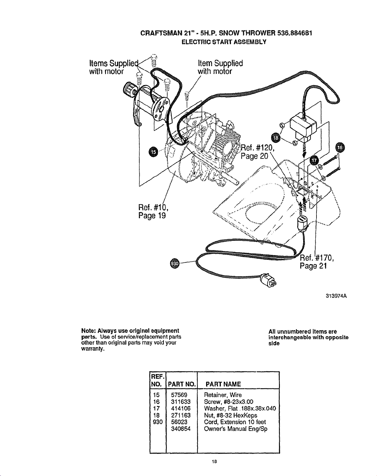
CRAFTSMAN 21" - 5H.P. SNOW THROWER 536.884681
ELECTRICSTART ASSEMBL¥
Item Supplied
with motor
#120,
2O
Ref. #1 ,
Page 19
\
\
\
i
M70,
Page 21
313974A
Note: Always use original equipment
parts. Use of servicelreptacement parts
other than original parts may void your
warranty.
All unnumbered ttems are
interchangeable with opposite
side
REF.
NO. PART NO.
15 57569
16 311633
17 414106
t 8 271163
930 56023
340854
PART NAME
Retainer, Wire
Screw, #8-23x3 00
Washer, Fiat 188x.3Bx.040
Nut, #8-32 HexKeps
Cord, Extension 10 feet
Owner's Manual Eng(Sp
18
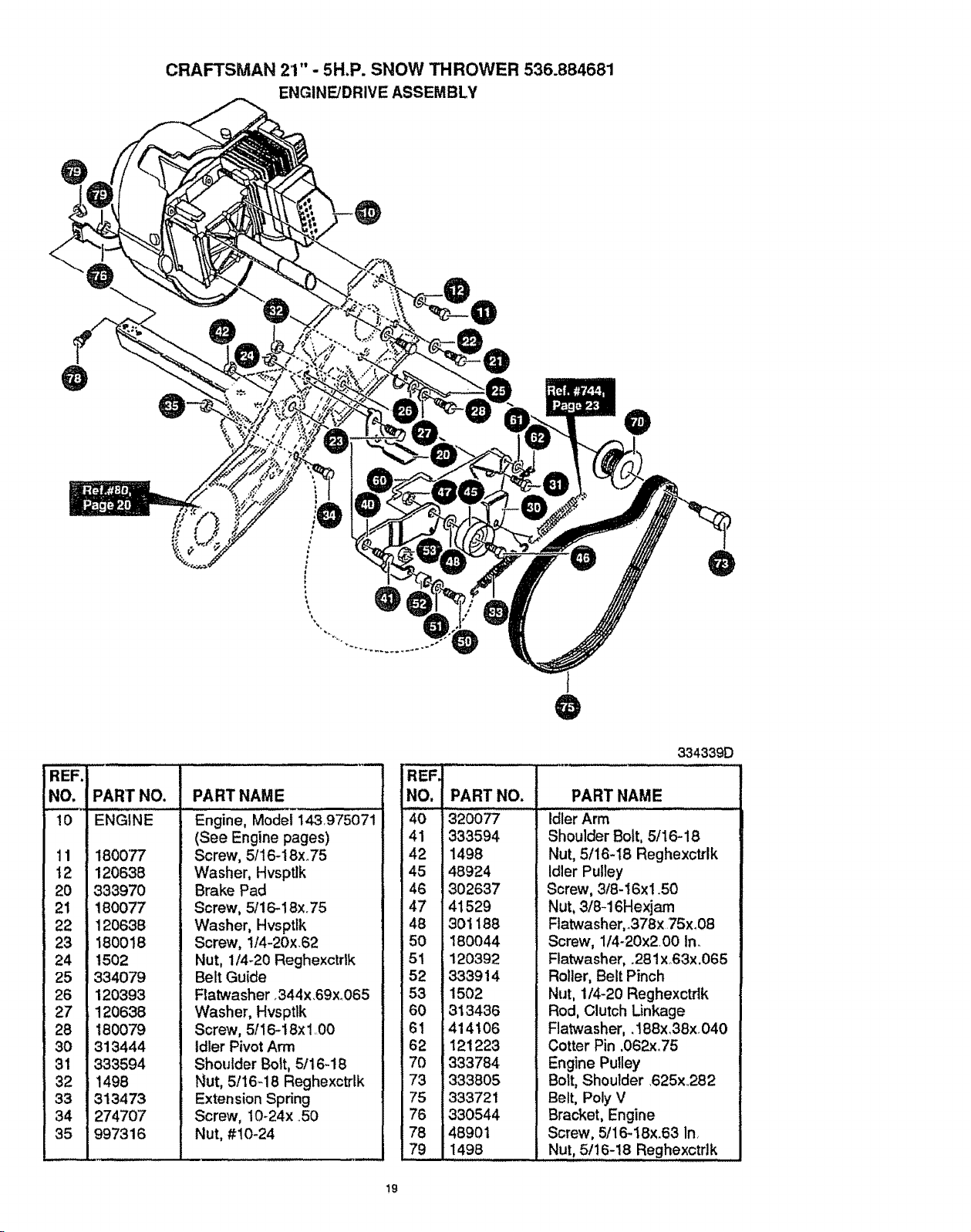
CRAFTSMAN 21" - 5H.P. SNOW THROWER 536.884681
ENGINE/DRIVE ASSEMBLY
REF'i
NO. ]
10
]
'q9
t2 1
2O J
_="* i
23
24 ]
25
26 I
,t,_"'t
28
30
31
32
33
34
35
PAR]" NO. PART NAME
ENGINE
180077
120638
333970
180077
120638
180018
1502
334079
120393
120638
180079
313444
333594
1498
313473
274707
997316
Engine, Model 143.975071
(See Engine pages)
Screw, 5/16-18xo75
Washer, Hvsptlk
Brake Pad
Screw, 5/16-18x.75
Washer, Hvsptlk
Screw, I/4-20x.62
Nut, 1/4-20 Reghexctdk
Belt Guide
Flatwasher o344x.69x.065
'Hasher, Hvsptlk
Screw, 5116-18x I O0
Idler Pivot Arm
Shoulder Bolt, 5/t6-18
Nut, 5/16-18 Reghexctrlk
Extension Spring
Screw, 10-24x ..50
Nut, #10-24
IREF.
NO,
40
41
42
45
46
47
48
50
51
52
53
6O
61
62
7O
73
75
76
78
79
PART NO.
320077
333594
1498
48924
302637
41529
301188
180044
120392
333914
1502
313436
414106
121223
333784
333805
333721
330544
48901
1498
334339D
PART NAME
Idler Arm
Shoulder Bolt, 5116-18
Nut, 5/16-18 Reghexctrlk
Idler Pulley
Screw, 3/8-16xi .50
Nut, 3/8-16Hexjam
Ftatwasher,.378x 75x.08
Screw, 1/4-20x200 Inn
Flatwasher, .28 ! xo63x.065
Roller, Belt Pinch
Nut, 1/4-20 Reghexctdk
Rod, Clutch Linkage
Flatwasher,. 188x.38x. 040
Cotter Pin ,062x..75
Engine Pulley
Bolt, Shoulder 625x.282
Belt, Poly V
Bracket, Engine
Screw, 5/16-18x.63 In.
.Nut, 5!1.6-18 Reghexctd k
t9
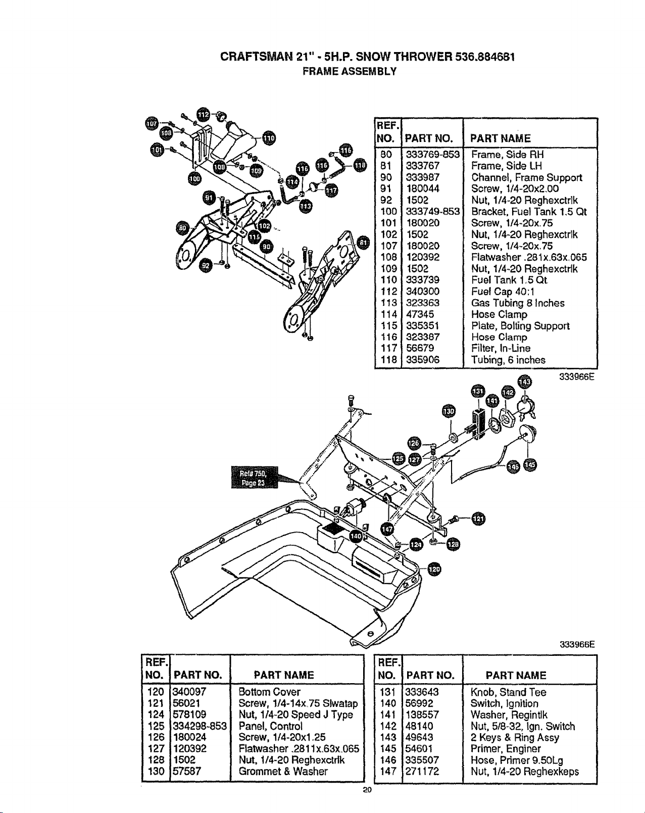
CRAFTSMAN 21" ,. 5H.P. SNOW THROWER 536.884681
FRAME ASSEMBLY
@
®
REF.
NO.
80
81
90
91
92
100
101
102
107
108
109
110
112
113
114
115
116
117
118
PART NO, PART NAME
333769-853
333767
333987
180044
1502
333749-853
180O20
1502
180020
120392
1502
333739
340300
323363
47345
335351
323387
56679
335906
Frame, Side RH
Frame, Side LH
Channel, Frame Support
Screw, t/4-20x2.00
Nut, 1/4-20 Reghexctrlk
Bracket, Fuel Tank 1.5 Qt
Screw, 1/4-20x.75
Nut, t/4-20 Reghexctrlk
Screw, 1/4-20x.75
Flatwasher. 281x..63x..065
Nut, 1/4-20 Reghexctflk
Fuel Tank 1o5Qt
Fuel Cap 40:1
Gas Tubing 8 inches
Hose Clamp
Plate, Bolting Support
Hose Clamp
Filter, In-Line
Tubing, 6 inches
@ 333966E
REF.
NO, PART NO.
12o34o097
121 56021
124 578109
125 334298,853
126 180024
127 120392
128 1502
130 57587
PART NAME
Screw, 114-14x.75 Slwatap
Nut, 1/4-20 Speed J Type
Panel, Control
Screw, 1t4-20xlo25
Flatwasher .2811x.63x..065
Nut, t14-20 Reghexctdk
Grommet & Washer
REF.
.o. I
13i
140
141
142
143
145
146
147
333966E
PART NO, PART NAME
Knob, Stand Tee
Switch, Ignition
Washer, Regintlk
333643
56992
138557
4814O
49643
54601
335507
271172
Nut, 5f8_32, lgn. Switch
2 Keys & Ring Assy
Primer, Enginer
Hose, Primer 9.50Lg
Nut, 1/4-20 Reghexkeps
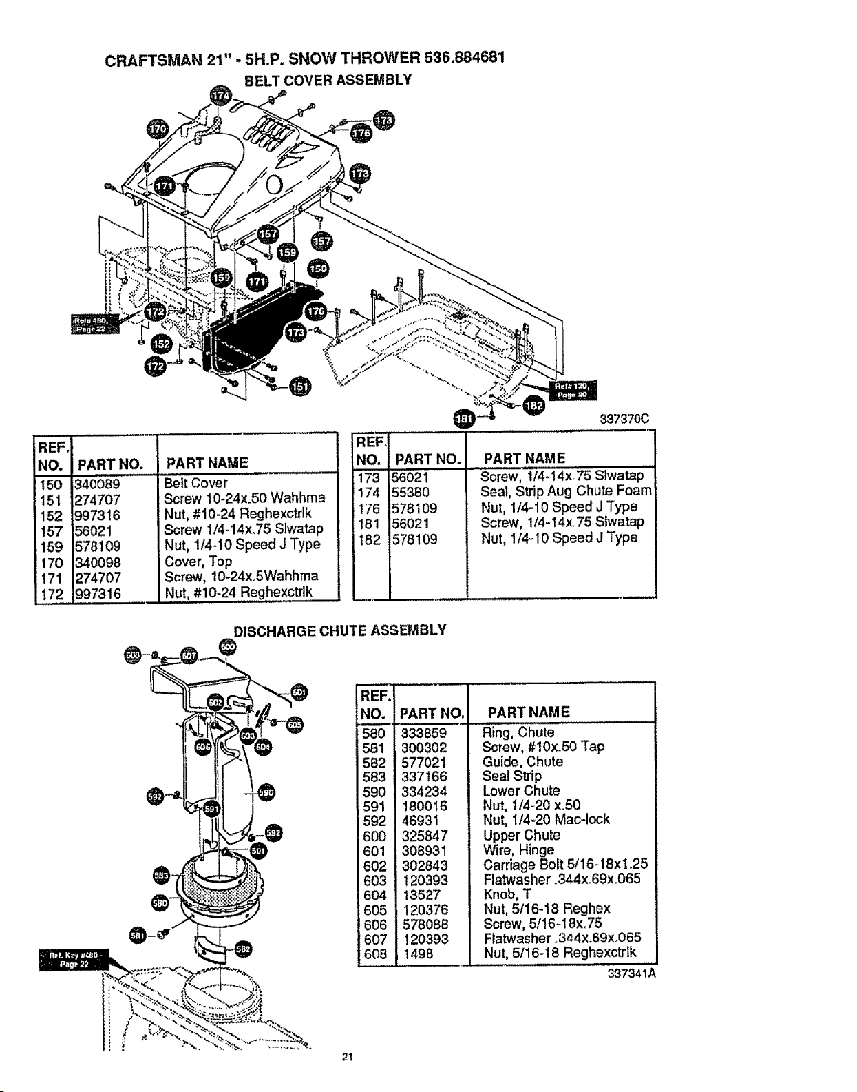
CRAFTSMAN 21" ,. 5H.P. SNOW THROWER 536.884681
BELT COVER ASSEMBLY
®
REF,
NO.
150
151
152
157
159
170
171
172
PART NO.
340'089
274707
997316
56021
578109
340098
274707
997316
PART NAME
, , i i,,,, ,, ....
Belt Cover
Screw 10-24x.50 Wahhma
Nut, #10-24 Reghexctrlk
Screw t/4-14x.75 Slwatap
Nut, 1/4-10 Speed J Type
Cover, Top
Screw, lO-24x.5Wahhma
Nut, #I0:24 Reghexctrlk
337370C
iREFo
NO. PART NO.
173 56021
174 55380
176 578t09
181 56021
182 578109
PART NAME
SQrew, 1/4-14x75 SIwatap
Seal, Strip Aug Chute Foam
Nut, 1/4-10 Speed J Type
Screw, 1/4-14x 75 Slwatap
Nut, 1/4-10 Speed J Type
DISCHARGE CHUTE ASSEMBLY
0
REF,
NO..
580
581
582
583
590
591
592
600
601
602
603
604
605
606
607
608
IPART NO,
333859
300302
577021
337166
334234
180016
46931
325847
308931
302843
120393
13527
120376
578088
12O393
1498
PART NAME
Ring, Chute
Screw, #10xo50 Tap
Guide, Chute
Seal Strip
Lower Chute
Nut, 1/4-20 x.50
Nut, 1/4-20 Mac-lock
Upper Chute
Wire, Hinge
Carriage Bolt 5/16-18xl.25
Flatwasher .344x.69x.065
Knob, T
Nut, 5/16-18 Reghex
Screw, 5/16-18x.75
Ftatwasher. 344 x.69x °065
Nut, 5/16- t 8 Reghexctdk
337341A
21
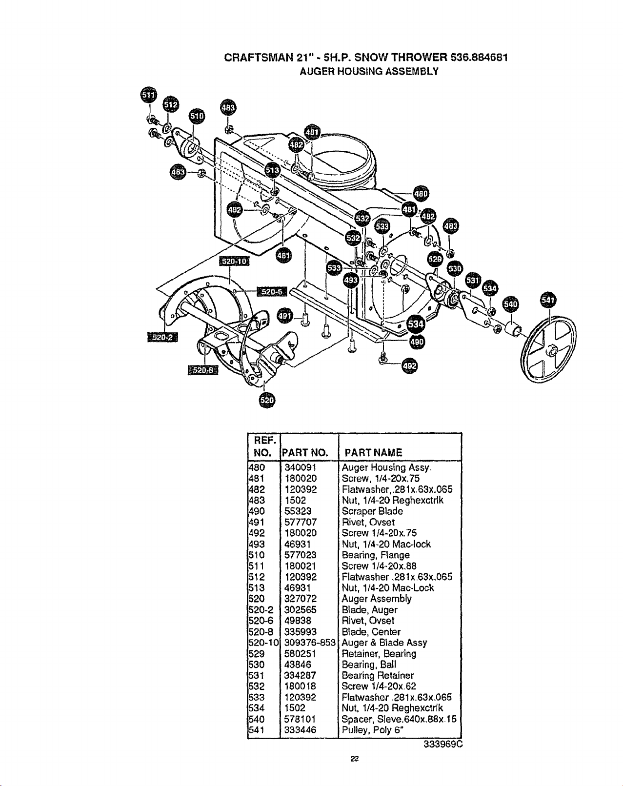
CRAFTSMAN 21"- 5H.P. SNOW THROWER 536.884681
AUGER HOUSING ASSEMBLY
REF.
NO.
480
481
482
483
490
491
492
493
510
511
512
513
520
520-2
520-6
i20-8
520-10
529
530
_31
532
$33
534
54O
541
PART NO.
340091......
180020
120392
1502
_55323
i577707
180020
,46931
_577023
180021
120392
46931
i327072
302565
!49838
335993
309376-853
1580251
43846
334287
180018
120392
t502
578101
i333446
PART NAME
iAuger HousingAssyl
iScrew, 1/4-20x.75
Flatwasher,.281x163xo065
Nut, 1/4-20 Reghexctrlk
Scraper Blade
i Rivet, Ovset
Screw 1/4-20x,75
Nut, 1/4420 Mac-lock
Bearing, Flange
Screw t/4-20x..88
Flatwasher. 281 x.63xo065
:Nut, 1t4-20 Mac-Lock
Auger Assembly
Blade, Auger
Rivet, Ovset
Blade, Center
;Auger & Blade Assy
Retainer, Bearing
Bearing, Ball
Bearing Retainer
Screw 114-20x,62
Ftatwasher .281 x,.63x.065
Nut, 1/4-20 Reghexctrlk
Spacer, Sleve.640x.88x.15
Pulley, Poly 6"
333969C
22
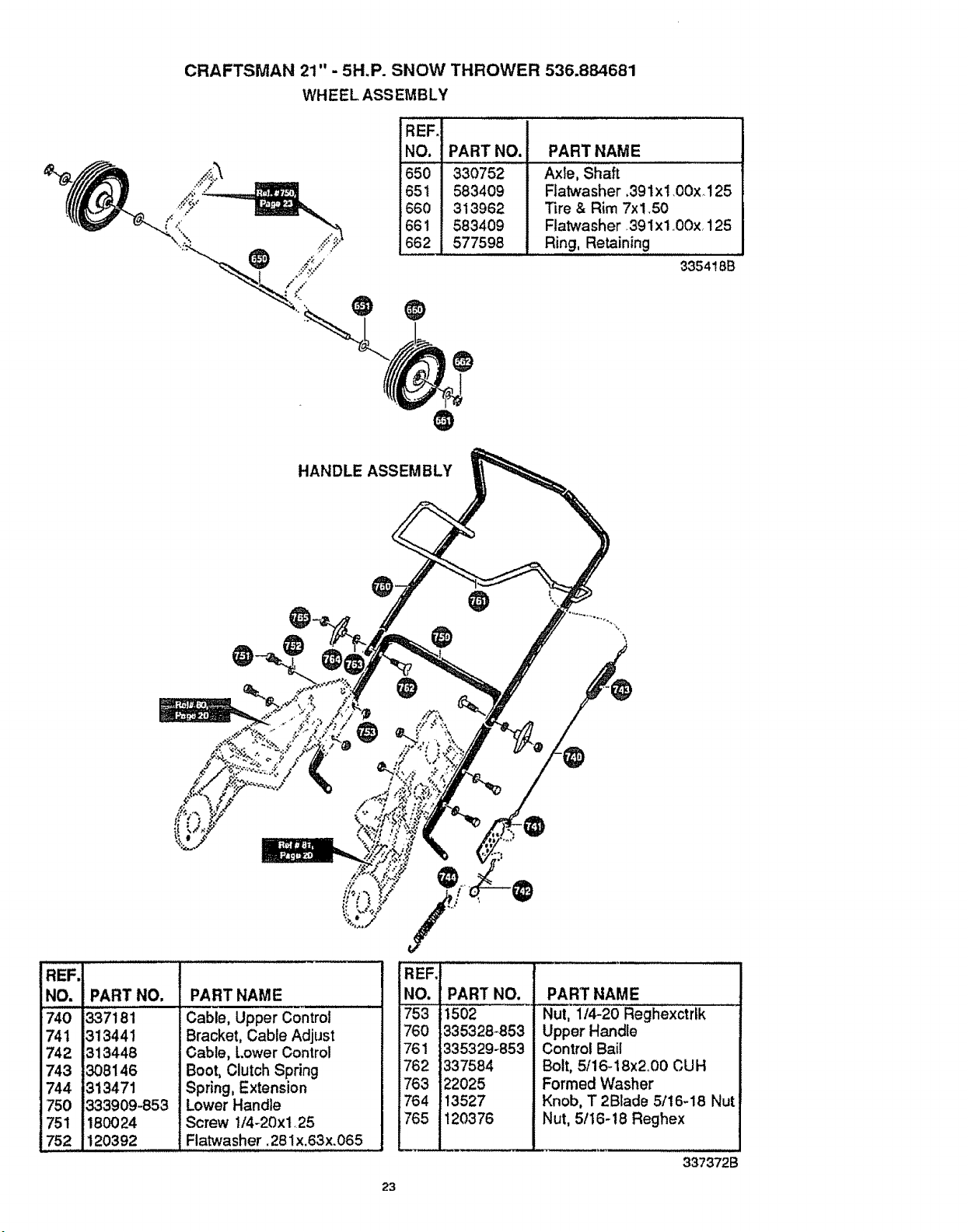
CRAFTSMAN 21" - 5H.P. SNOW THROWER 536.884681
WHEEL ASSEMBLY
@
REF.
NO. PART NO.
650 330752
651 583409
660 313962
661 583409
662 577598
PART NAME
Axle, Shaft
Flatwasher .39 lx 1.00x, 125
Tire & Rim 7x!50
Flatwasher .39 lx 1 ,,00x.125
Ring, Retaining
3354! 8B
HANDLE ASSEMBLY
REF.
NO. PART NO.
740 337181
74t
742
743
744
750
751
752
313441
313448
308146
313471
1333909-853
180024
120392
PART NAME
Cable, Upper Coniroi '
Bracket, Cable Adjust
Cable, Lower Control
Boot, Clutch Spring
Spring, Extension
Lower Handle
Screw t/4-20xl.25
Flatwasher. 281x.63x.065
REF.:
NO.i
760!
761
762 :
763 1
764
765 i
PART NO.
1502
335328-.853
1335329-853
337584
22025
13527
120376
I
i
23
____.J
PART NAME
Nut, 1/4-20 Reghexctrlk
Upper Handle
Control Bail
Bolt, 5/16,-18x2o00 CUH
Formed Washer
Knob, T 2Blade 5/16-18 Nut
Nut, 5/t6-18 Reghex
337372B
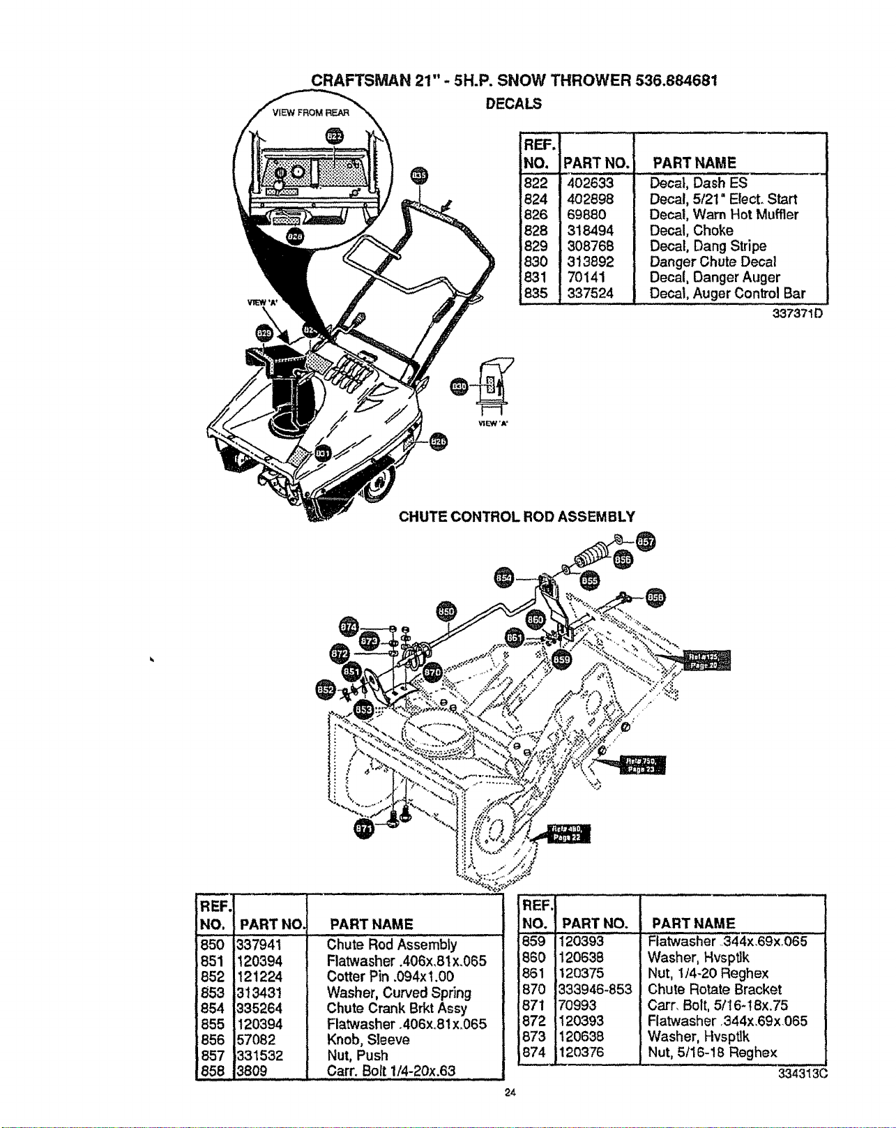
CRAFTSMAN 21" - 5H.P. SNOW THROWER 536.884681
DECALS
R_.
NO.
822
824
826
828
829
83O
831
.836
PART NO,
402633
402898
69880
318494
308768
313892
70141
337524
PART NAME
Decal, Dash ES
Decal, 5121=Elect. Start
Decal, Warn Hot Muffler
Decal, Choke
Decal, Dang Stripe
Danger Chute Decal
Decal, Danger Auger
Decal, Auger Control Bar
337371D
CHUTE CONTROL ROD ASSEMBLY
-0
REF. 1
NO.
850
851
852
853
854
855
856
857
858
I
PART N°'I PART NAME ....
337941 ' Chute Rod ASsembly
120394 Flatwasher .406x.81 x.065
121224 Cotter Pin .094x 1.00
313431 Washer, Curved Spring
335264 Chute Crank Brkt Assy
120394 Flatwasher .406xo81x.065
57082 Knob, Sleeve
_331532 Nut, Push
3809 Carr. Bolt 1/4-20x.63
IREKI
NO. ! PART NO.
185gll_o393......
186o 112o638
1861 1120375
1870 1333946-853
187_170993
18_2!I20393
18731120638
87L_120376
PART NAME
Flatwasher 344x.69x_065
Washer, Hvsptlk
Nut, 1/4-20 Reghex
Chute Rotate Bracket
Carr_ Bolt, 5/16-I 8x.75
Flatwasher o344x_69xO65
Washer, Hvsptlk
Nut, 5tl 6-1B Reghex
3343130
24
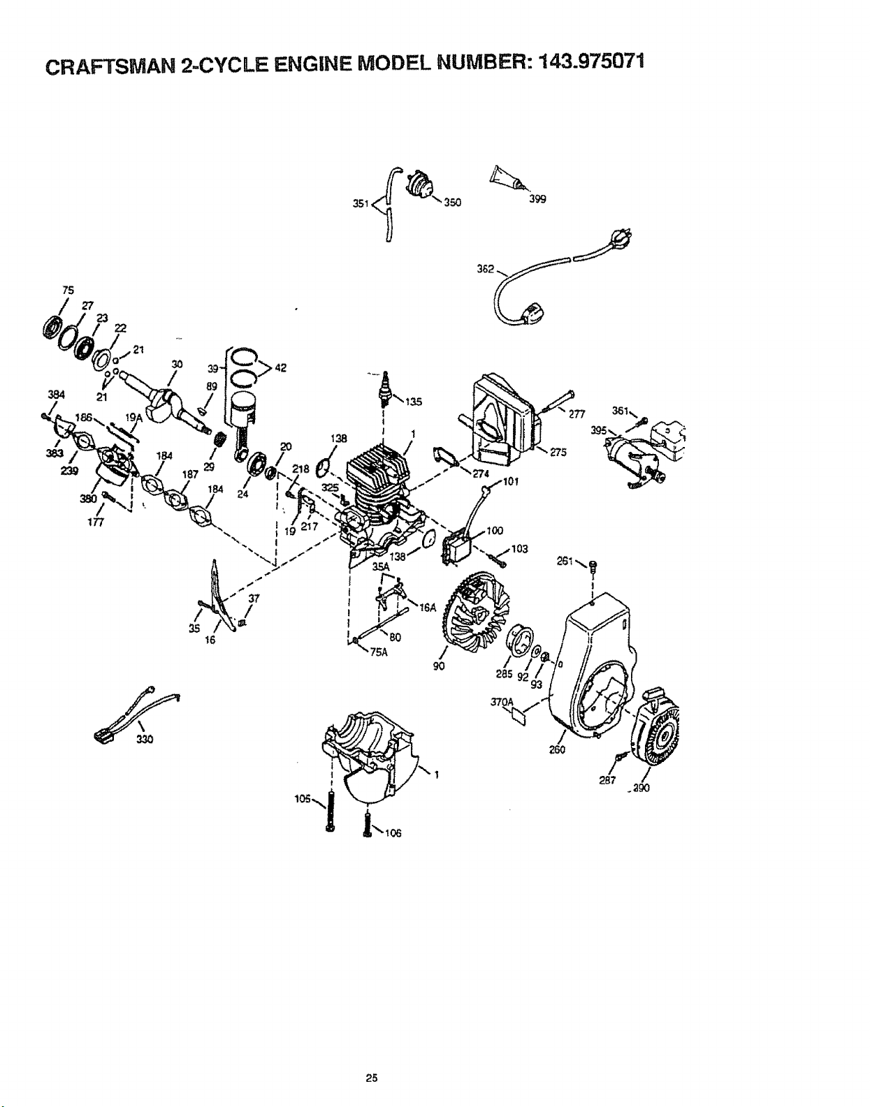
CRAFTSMAN 2,.CYCLF_ F,NGINE MODEL NUMBER: 143.975071
351_ 350
75
384
27
23
21
22
30
/
42
t
t
I
!
285
370A
260
287
25
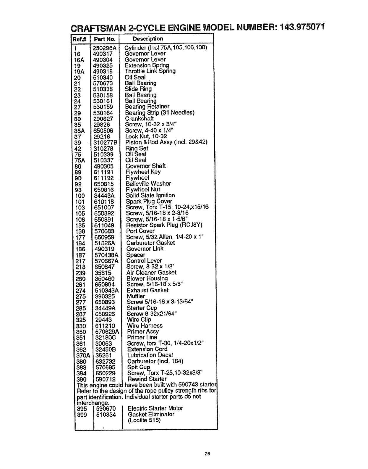
CRAFTSMAN 2-CYCLE ENGINE MODEL NUMBER: 143.975071
,i
1 250296A
16 490317
16A i490304
19 490325
19A _4903t8
20 1510340
21 i570673
22 !510338
23 530158
24 530161
27 530159
29 530164
30 290627
35 29826
35A 650506
37 29216
39 310277B
42 310278
75 51O339
75A 510337
80 490305
!89 611191
i90 611192
92 650815
93 650816
100 34443A
101 1610118
I03 651007
105 650892
106 650891
135 611049
138 570683
177 650959
184 51326A
186 490319
187 570438A
2t7 570667A
218 650847
239 35815
260 350460
261 650894
i274 510343A
i275 390325
277 650893
285 34449A
287 650926
325 29443
330 611210
350 570629A
351 32180C
361 30063
362 32450B
370A 36261
380 632732
383 570695
384 650229
390 590712
Ref,# Part No. Description
d'ylinder (lnc175A,:i05, t00,1_'i ....
Governor Lever
Governor Lever
Extension Spring
Throttle Link Spring
Oil Seal
Ball Bearing
Slide Ring
Ball Bearing
Ball Bearing
Bearing Retainer
BearingStrip (31 Needles)
Crankshaft
Screw, 10-32 x 3/4"
Screw, 4-40 x 1/4"
Lock Nut, 10-32
Piston &Rod Assy (inc[ 29&42)
RingSet
Oil Seal
Oil Seal
Governor Shaft
Flywheel Key
Flywheel
Bellevitle Washer
FlYwheel Nut
Solid State Ignition
Spark Plug Cover
Screw, Torx T-15, 10-24,x15/16
Screw, 5/16-18 x 2-3!16
Screw, 5/16_18 x 1-.5/8"
Resistor Spark Plug (RCJSY)
Port Cover
Screw, 5/32 Allen, 1/4-20 x 1"
Carburetor Gasket
Governor Unk
Spacer
Control Lever
Screw, 8-32 x 1/2"
Air Cleaner Gasket
Blower Housing
Screw, 5/16-18 x 518"
Exhaust Gasket
Muffler
Screw 5/I6-18 x 3-13/64"
Starter Cup
Screw 8-32x21/64"
Wire Clip
Wire Harness
Primer Assy
Primer Line
Screw, torx T-30, 1/4-20xl/2"
Extension Cord
Lubrication Decal
Carburetor (Inol.. I84)
Spit Cup
Screw, Torx "1"-25,t0-32x3/8"
Rewind Starter
This engine coulcl have been built with 590743 starte
Refer to _e design of the rope pulley strength ribs fol
..part identification. Individual starter parts do not
interchange.
395 590670 Electric Starter Motor
399 510334 Gasket Eliminator
(Lootite 515)
26
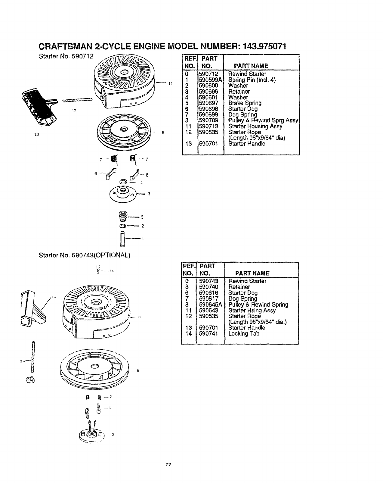
CRAFTSMAN 2-CYCLE ENGINE MODEL NUMBER: 143.975071
Starter No. 590712
13
12
(_)_ 4
_REF!
.o.i
3 I
!5 i
18 '
Ill I
i12 !
i •
113
PART
NO.
590712
590599A
590600
590696
590601
590697
590698
590699
590709
590713
590535
5907o1
PART NAME
Rewind Starter
S&ring Pin (fnd_ 4)
sher
Retainer
Washer
Brake Spring
Starter Dog
Dog Spring
Pulley & Rewind Sprg Assy
Starter Housing Assy
Starter Rope
(Length 98"x9/64" dia)
Starter Handle
Starter No. 590743(OPTIONAL)
_-°
REF.
NO.
0
3
6
7
8
11
12
13
14
PART
NO.
590743
590740
590616
590617
590645A
590643
590535
590701
590741
PART NAME
Rewind Starter
Retainer
Starter Dog
Dog Spring
Pulley & Rewind Spring
Starter Hsing Assy
Starter Ro,p,e .
(Length 99'x9164 dia.,)
Starter Handle
Locking Tab
27
CRAFTSMAN 2-CYCLE ENGINE MODEL NUMBER: 143.975071
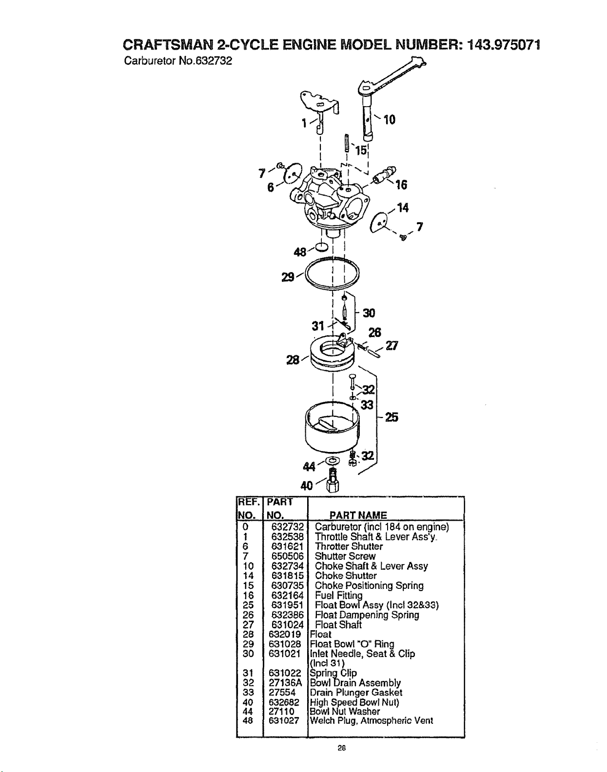
Carburetor No,632732
!
I
1
7
7
291(
NO. i
0
1
6
7
10
14
15
16
25
26 ,
27
28
29
30
31
32
33
40
44
48
1
30
31 26
Z7
-PAFiT
NO.
632732
632538
631621
650506
632734
631815
630735
632164
631951
632386
631024
632019
631028
631021
631022
27136A
27554
632682
27110
631027
PART NAME
Carburetor (inc1184 on engine)
Throttle Shaft & Lever Ass'y,_
Throtter Shutter
Shutter Screw
Choke Shaft & Lever Assy
Choke Shutter
Choke Positioning Spring
Fuel Fitting
Float BowlAss.y (Inc132&33)
Roar Dampemng Spring
Roat Shaft
Float
Float Bowl "O" Ring
Inlet Needle, Seat & Clip
(Incl 31)
SpringClip
Bowl Drain Assembly
Drain Plunger Gasket
High Speed Bowl Nul)
Bowl Nut Washer
_/elch Plug, Atmospheric Vent
28
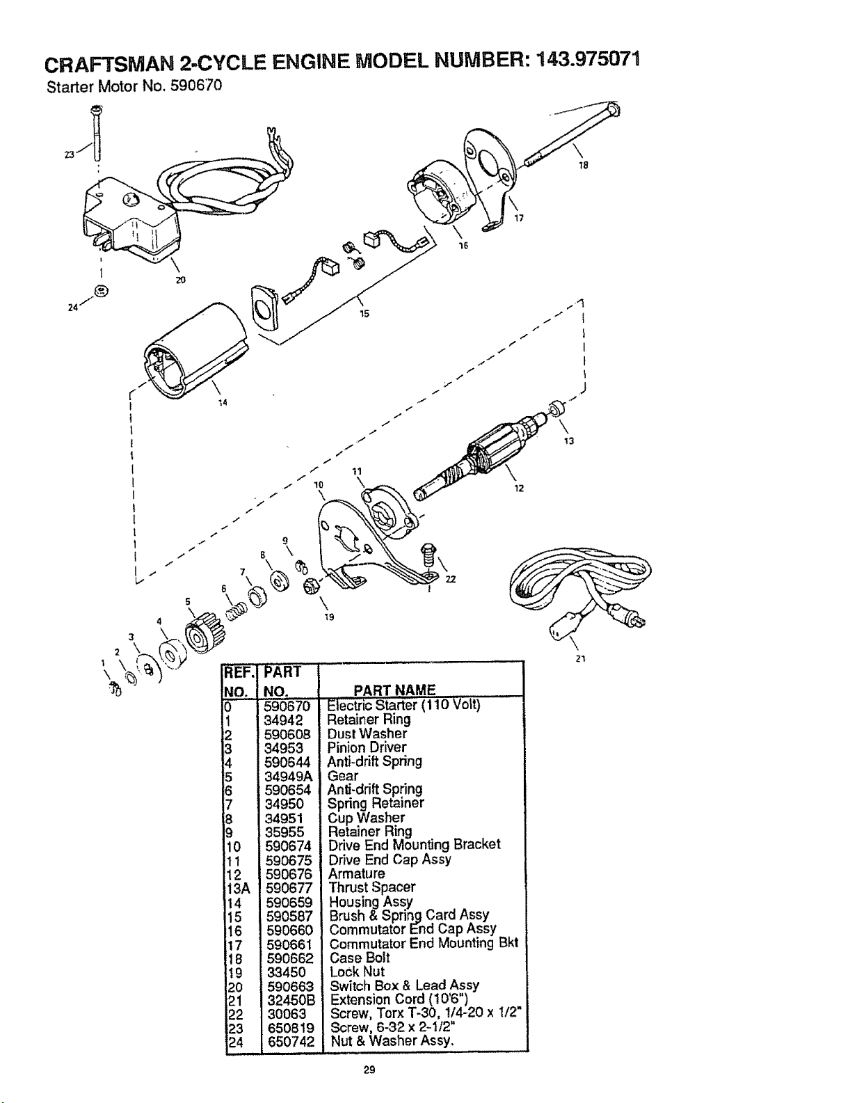
CRAFTSMAN 2-CYCLE ENGINE MODEL NUMBER: 143.975071
Starter Motor No. 590670
'f
f
t
!
i 7
b-
6
3 \
% NO.
0
I
2
3
4
5
6
7
8
9
10
11
12
13A
14
15
16
17
IB
19
20
21
22
23
24
.f
9
\
PART ....
NO. PART NAME
590670 EleCtric Starter (110 V01t)
34942 Retainer Ring
590608 Dust Washer
34953 Pinion Driver
590644 Anti-drift Spring
34949A Gear
590654 Anti-drift Spring
34950 SF ring Retainer
34951 C_ p Washer
35955 Retainer Ring
590674 Drive End Mounting Bracket
590675 Drive End Cap Assy
590676 Armature
590677 Thrust Spacer
590659 Housing Assy
590587 Brush & Spring Card Assy
590660 Commutator End Cap Assy
590661 Commutator End Mounting Bkt
590662 Case Bolt
33450 Lock Nut
590663 Switch Box 8, Lead Assy
32450B Extension Cord (10'6")
30063 Screw, Torx T-30, 1/4-20 x 1/2"
650819 Screw, 6-32 x 2-1/2"
650742 Nut & Washer Assy.
12
21
29
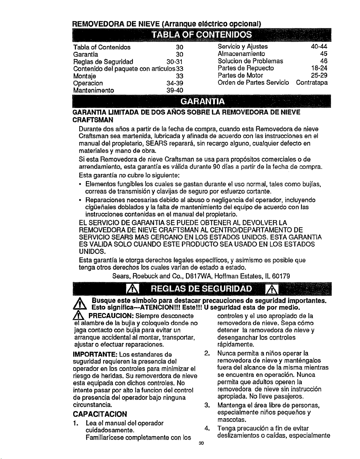
REMOVEDORA DE NIEVE (Arranque el_ctrico opcional)
Tabla of Contenidos 30
Garantia 30
Reglas de Seguridad 30-31
Contenido del paquete con articulos33
Montaje 33
Operacion 34-39
Mantenimento 39-40
Servicio y Ajustes 40-44
Almacenamiento 45
Solucion de Problemas 46
Partes de Repuecto 18-24
Partes de Motor 25-29
Orden de Partes Servicio Contratapa
GARANTIA UMITADA DE DOS AI_IOS SOBRE LA REMOVEDORA DE NIEVE
CRAFTSMAN
Durante dos aries a partir de la fecha de compra, cuando esta Removedora de nieve
Craftsman sea martenida, lubricada y afinada de acuerdo con las instrucciones en et
manual del propietario, SEARS reparar_., sin recargo alguno, cualquier defecto en
materiales y mane de obra.
Si esta Removedora de nieve Craftsman se usa para propSsitos comerciales o de
arrendamiento, esta garantfa es v&lida durante 90 dias a partir de la fecha de compra.
Esta garantia no cubre 1o siguiente:
• Elementos fungibles los cuales se gastan durante el use normal, tales come bujfas,
correas de transmisiSn y clavijas de seguro per esfuerzo cortante.
• Reparaciones necesarias debido al abuse o negligencia de! operador, inctuyendo
cigDeSales dobtados y la falta de mantenimiento del equipo de acuerdo con las
instrucciones contenidas en el manual del propietario.
EL SERVICIO DE GARANTIA SE PUEDE OBTENER AL DEVOLVER LA
REMOVEDORA DE NIEVE CRAFTSMAN AL CENTROiDEPARTAMENTO DE
SERVICIO SEARS MAS CERCANO EN LOS ESTADOS UNIDOS° ESTA GARANTIA
ES VALIDA SOLO CUANDO ESTE PRODUCTO SEA USADO EN LOS ESTADOS
UNIDOS.
Esta garantl'a le otorga derechos legales especfficos, y asimismo es posible que
tenga otros derechos los cuales varfan de estado a estado.
Sears, Roebuck and Co., D817WA, Hoffman Estates, IL 60179
/k
PRECAUCION: Siempre desconecte
el alambre de la bujia y coloquelo donde no
jaga contacto con bujia para evitar un
arranque accidental al montar, transportar,
ajustar o efectuar reparaciones.
Busque este simbolo para destacar precauciones de seguridad importantes.
Esto signlflca-.ATENCIONt!! Este!!! U segurldad esta de per medio.
IMPORTANTE: Los estandares de
suguridad requieren la presencia del
operador en los controles para minimizar el
riesgo de heridas. Su removerdora de nieve
esta equipada con dichos controles. No
intento pasar per alto la funcion del control
de presencia del operador bajo ninguna
circunstancia.
CAPACITACION
1. Lea el manual del operador
cuidadosamente.
Familiaricese completamente con los
controles y el use apropiado de ia
removedora de nieve. Sepa c6mo
detener la removedora de nieve y
desenganchar los controtes
r&pidamente.
2. Nunca permita a niff,os operar la
removedora de nieve y mant_ngalos
fuera del alcance de la misma mientras
se encuentra en operaci6n. Nunca
permita que adultos operen ]a
removedora de nieve sin instrucciOn
apropiada, No Ileve pasajeroso
3, Mantenga el &rea libre de personas,
especialmente nifos peque5os y
mascotas.
4. Tenga precauciSn a fin de evitar
deslizamientos o caidas, especialmente
30
al operar la removedora de nieve en
retroceso.
PREPARAOION
1. Inspeccionecompletamenteel &rea
donde se usar_, la removedora de
nieve y retire todas las esteras, trineos,
tableros, alambres, y otros objetos
extrafioso
2_
o
#
Desenganche todos los embragues y
cambie a neutro antes de arrancar el
motor.
No opere la removedora de nieve sin
vestir las prendas de invierno
adecuadas para ambientes exteriores.
Vista caizado que mejore su
estabilidad en superficies lisas.
Maneje el combustible con cuidado; es
a!lamente inflamable.
(a) Use un contenedor para combus
tible aprobado_
(b) Nunca retire la tapadera det
tanque de combtible o afiada combus
tible a un motor en marchao a un motor
caliente.
(c) Llene el tanque para combustible
at aire libre, con cuidado extremo.
Nunca llene el tanque en ambientes
interiores.,
7_
(d) Coloque nuevamente latapadera
del tanque paracombustible de manera
segura y limpie el combustible
derramado.
(e) Nunca almacene combustible o la
removedora de nieve con combustible
en el tanque dentro de un edificio
donde los vapores pudiesen entrar en
contacto con una llama desprotegida o
una chispa.
(f) Verifique las existencias de corn
bustible antes de cadauso, permitiendo
espacio para expansi6n puesto que
el calor del motor y/o el sol pueden
causar la expansi6n del combustible.
Use cables de extensiSn y
recept&culos de la manera
especificada por el fabricante para
todas las removedoras de nieve con
motores accionados por energfa
el_ctrica o motores de arranque
el6ctrico.
Ajuste la altura de la removedora de
nieve para pasar sobre superficies de
grava o piedra triturada.
Jam_.s intente efectuar ning_n ajuste
mientras e! motor se encuentra en
marcha (excepto cuando el fabricante Io
recomiende asi especfficamente)o
8. Permita que el motor y la removedora
de nieve se ajusten a tas temperaturas
extefiores antes de comenzar a retirar la
nieve,,
9. Siempre use gafas de seguridad o
protectores para los ojos durante la
operaciSn o mientras se efect_a un
ajuste o reparaciSn para proteger sus
ojos de objetos extrafios que pudiesen
set lanzados por la removedora de
nieve.
OPERAClON
31
1. No coloque las manos o los pies cerca
o bajo piezas rotativas. Mant6ngase a
distancia de la abertura para descarga
todo el tiempoo
2 No opere esta m,_quina si est& tomando
drogas u otras medicinas que pudiera
causar somnolencia o que pudieran
afectar su habilidad para operar esta
m&quina.
3. No opere esta m&quina si su estado
emocional o fisico no le permite
operaria con segur[dad.
4. Tenga precauci6n extrema at operar
sobre o al cruzar caminos, aceras, o
calles de grava. Mant_ngase alerta en
caso de peligros ocultos o tr_.fico.
5. Despu_s de golpear un objeto extrafio,
pare el motor, retire el alambre de la
bujia, desconecte el cable en motores
el_ctricos, inspeccione completamente
la removedora de nieve a fin de
encontrar cualquier dafio, y reparar
dicho daP,o antes de arrancar y operar
la removedora de nieve nuevamente.
6. En el caso de que la removedora de
nieve comience a vibrar fuera de Io nor-
mal, pare el motor y revise la m&quina
inmediatamente para encontrar la
causao Generalmente, la vibraciSn es
una advertencia de problemas.
7. Pare el motor dondequiera que deje la
posici6n de operaci6n, antes de
desobstruir el alojamiento del barreno!
propulsor o guia de descarga, y cuando
efectL'Je cualesquiera reparaciones,
ajustes, o inspecciones.
8. AI limpiar, reparar, o inspeccionar la
m_qutna aseg0rese de que el barreno/
propulsor y toda parte m6vil se hayan
detenido. Desconecte el alambre de la
bujia y mant_ngalo alejado de Ia buj{a
para evitar un arranque accidental.
9. No ponga en marcha el motor en
ambientes interiores, excepto al
arrancar el motor y para transportar la
removedora de nieve hacia adentro o
hacia afuera del edificio. Abra las
puertas extefiores; el humo det escape
es peligroso (contiene MONOXIDO DE
CARBONO, un GAS INODORO y
LETAL),
10. No timpie nieve perpendicularmente a
la direcci6n de pendientes, Tenga
precauci6n al cambiar de direcci6n en
pendientes. No intente limpiar
pendientes pronunciadas.
11. Nunca opere la removedora de nieve
sin que los resguardos, placas u otros
dispositivos de seguridad se
encuentren en su lugar.
12. Nunca opere ta removedora de nieve
cerca de recintos de vidrio,
autom6viles, huecos de ventanas,
sitios de carga/descarga, y similares
sin el ajuste apropiado del &ngulo de
descarga de ta nieve. Mantenga niSos
y mascotas alejados.
13. No sobrecargue la capacidad de la
m&quina al intentar limpiar nieve a una
velocidad demasiado r&pida.
14. Nunca opere la removedora de nieve a
altas velocidades de transporte sobre
superficies resbalosas, Mire hacia atr&s
y tenga cuidado al retroceder.
15. Nunca descargue directamente sobre
espectadores ni permita a nadie frente
a la removedora de nieve,
!6.
Desenganche la fuerza motriz ai
barreno/propulsor cuando la
removedora de nieve sea transportada
o est_ fuera de uso.
17. Utilice t_nicamente aditamentos y
accesorios aprobados por et fabricante
de la removedora de nieve (tales como
cadenas antiderrapantes para las
Ilantas, juegos de arranque el_ctrico,
etc.).
18. Nunca opere la removedora de nieve
sin buena visibilidad o iluminaci6n.
Siempre est6 seguro de su estabilidad,
y mantenga un agarre firme de las
manijas. Oamine; jam_.s corra.
MANTENIMIENTO Y
ALMACENAMIENTO
1. Revise los pernos de seguro por
esfuerzo cortante y otros pernos que
frecuentemente no est&n apretados
adecuadamente para asegurarse de
que la removedora de nieve est& en
condiciones seguras de trabajo.
2. Nunca almacene )a removedora de
nieve con combustible en el tanque
para combustible dentro de un edificio
en el cual se encuentran presentes
{uentes de ignici6n tales como agua
caliente y calentaclores de espacio,
secadoras de ropa, y similares. Permita
que et motor se enfrie antes de
almacenarlo en cuatquier recinto.
3. Siempre refi_rase alas instrucciones
del manual del operador para consulta
de los detalles importantes si la
removedora de nieve ser& almacenada
durante un perfodo de tiempo
prolongado.
4. Mantengao coloque de nuevo tas
etiquetas de seguridad e instrucciones,
de acuerdo a to que sea necesarioo
5. Mantengala removedora de nieve en
marcha unos cuantos minutos despu6s
de tirar la nieve para evitar el
congelamiento del barreno/propufsor.
,/_ ADVERTENCIA: Esta removedora
de nieve se usa para aceras, caminos de
entrada, y otras superficies de terreno
planas. Se debe tener mucha
PRECAUCION al utilizarla en superficies
con pendiente pronunciada. NO USAR
LA REMOVEDORA DE NIEVE SOBRE
SUPERFICIES POR ENCIMA DEL
NIVEL DEL TERRENO, tales como
techos de residencias, cocheras, porches
u otras de tales estructuras o edificios.
ADVERTENCIA: Las emanaciones
de escape producidas por este motor
contienen quimicos reconocidos por el
Estado de California como carcinSgenos,
tambi6n pueden produeir defectos en los
reci_n nacidos o causar otros daEos al
sistema reproductivo.
32
Contenido de la bolsa con las partes
1 - Envase Craftsman de 100cc(3,2 oz) de
acette_ 2 tiempos
1 - Manuel de! Duefio (no muestra)
1 - Boise con Jas parles (no muestra)
1 - Cuerda del arrancador el_=ctr|co 10 ft,
Z_ PRECAUCION: Siempre use galas
protectoras o protectores para los ojos
cuando monte la removedora de nieve_
HERRAMIENTAS REQUERIDAS
PARA EL MONTAJE
1 - Navaja (para cortar cart6n y ataduras
pl_sticas)
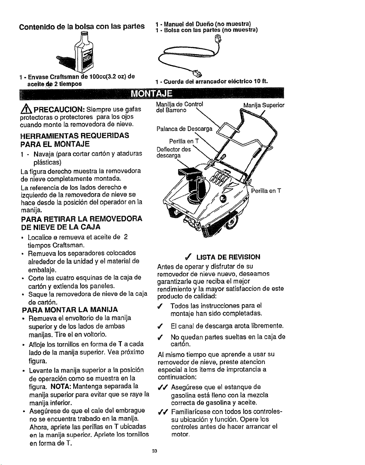
La figura derecho muestra la removedora
de nieve completamente montada.
La referencia de los lados derecho e
izquierdo de la removedora de nieve se
hace desde la posici6n del operador en la
manija.
PARA RETIRAR LA REMOVEDORA
DE NIEVE DE LA CAJA
• Localice e remueva et aceite de 2
tiempos Craftsman.
, Remueva los separadores cotocados
alrededor de la unidad y el material de
embalaje.
= Corte las cuatro esquinas de la caja de
cart6n y extienda los paneles.
• Saque la removedora de nieve de la caja
de cart6n.
PARA MONTAR LA MANIJA
- Remueva et envoltodo de Jamanija
superior y de los lados de ambas
manijas. Tire el en voltorio.
, Afloje los tornitlos en forma de T a cada
lado de la manija superior. Vea pr6ximo
figura.
- Levante ta manija superior a ta posici6n
de operaci6n como se muestra en la
figurao NOTA: Mantenga separada [a
manija superior para evitar que se raye ta
manija inferior.
• Asegl3rese de que el cale del embrague
no se encuentra trabado en la manija.
Ahora, apriete tas perillas en T ubicadas
en ia manija superior. Apriete los tornilios
en forma de T.
Palanca de Descarga
Perilla en T
Deflector des
descarga
Manija Superior
Perilla en T
J' LISTA DE REVISION
Antes de operar y disfrutar de su
removedor de nieve nuevo, des_amos
garantizarle que reciba el mejor
rendimiento y ta mayor satisfaccion de este
producto de calidad:
4' Todos las instrucciones para el
montaje ban sido completadas.
4' El canal de descarga arota tibremente.
4' No quedan partes sueltas en la caja de
carton.
AI mismo tiempo que aprende a usar su
removedor de nieve, preste atencion
especial a los items de improtancia a
continuacion:
,/,/ AsegSrese que el estanque de
gasolina est,_ tleno con la mezcla
correcta de gasolina y aceite.
4'#' Familiaricese con todos los controles-
su ubicaci6n y _unciOno Opere los
controles antes de hacer arrancar el
motor°
33
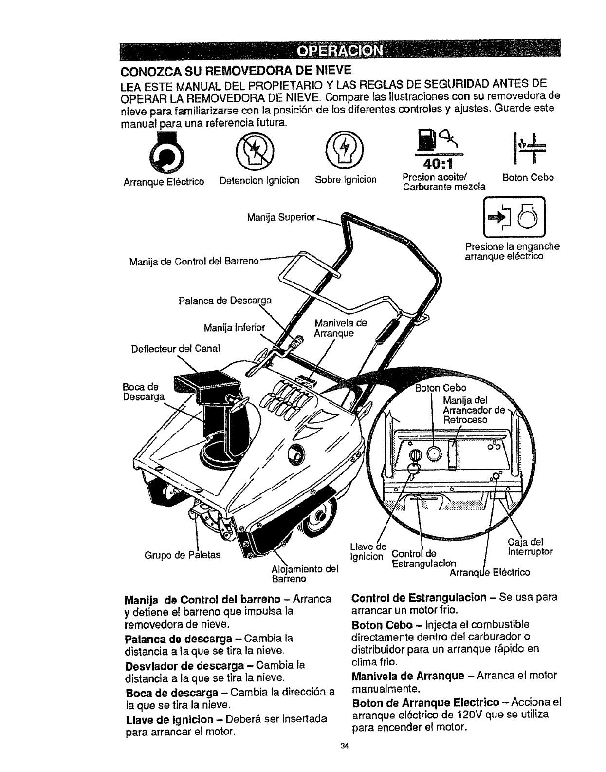
CONOZCA SU REMOVEDORA DE NIEVE
LEA ESTE MANUAL DEL PROPIETARIO Y LAS REGLAS DE SEGURIDAD ANTES DE
OPERAR LA REMOVEDORA DE NIEVE, Compare las itustraciones con su removedora de
nieve para familiarizarse con la posici6n de los diferentes contmtes y ajustes, Guarde este
manual para una referencia futura.
Arranque EI6ctrico Detencion !gnicion Sobre Ignition Pre_ion aceite/ Boron Cebo
Carburan te mezcla
Manija de Control del
Man_a
I÷6
Presione la enganche
arranque el_ctrico
Palanca de
Manija Inferior
\
Detlecteur del Canal
%
Manivela de
A_anque
Boca de
Desca_a
Cebo
a del
Retroceso
Grupo de P;
X
Alojamiento del
Barreno
Manija de Control del barreno- Arranca
y detiene et barreno que imputsa la
removedora de nieve.
Palanca de descarga -Cambia la
distancia a la que se tira la nieve.
Desvlador de descarga -Cambia la
distancia a la que se tira la nieve,
Boca de descarga - Cambia la direcci6n a
la que se tira la nieve.
Llave de igniclon - Deber_ set insertada
para arrancar el motor,
34
Llave _e del
Ignidon Contro de ntermp_r
Es_angulacion
El_ctdco
Control de Estrangulacion - Se usa para
arrancar un motor frio,
Boton Cebo - Injecta el combustible
directamente dentro del carburador o
distribuidor para un arranque rApido en
clima frio.
Manivela de Arranque - Arranca el motor
manualmente.
Boton de Arranque Electrico - Acciona el
arranque el_ctrico de 120V que se utiliza
para encender el motor.
La operaci6n de cualquier removedora de
nieve puede ocasionar que objetos extraSos
sean lanzados dentro de sus ojos, to cual
podr|a resultar en daSos severos a los ojos.
Use siempre gafas de seguridad o
protectores para los ojos mientras opere la
removedora de nieve. Se recomiendan las
gafas de seguridad est&ndar o la m#,scara
de seguridad de visiSn amplia para usarla
sobre los anteojos disponibles en todas las
tiendas SEARS o Center de Servicio
SEARS.
Z_ PRECAUClON: Lea el manual del
propietario antes de operar la maquina.
Nuncas dirija la descarga hacia los
peatones. Suette la palanca del conmutador
de control y apague el motor antes de
desatascar e_ canal de descarga o el
alojamiento del barreno y antes de dejar la
maquina.
COMO USAR SU REMOVEDORA DE
NIEVE
PARA DETENER SU REMOVEDORA DE
NIEVE
- Para parar el barreno o motor,
desenganchada manija de control del
barreno.
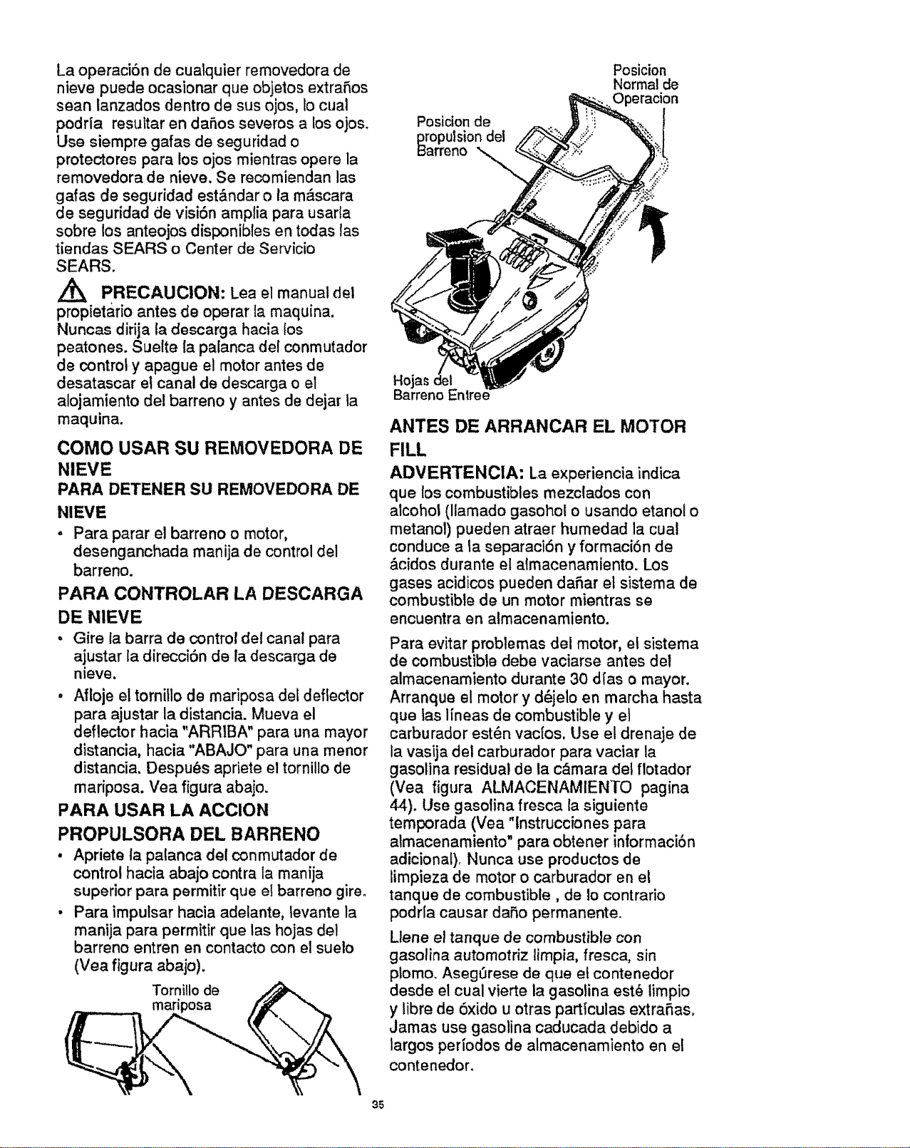
PARA CONTROLAR LA DESCARGA
DE NIEVE
• Gire ta barra de control del canal para
ajustar la direcciSn de la descarga de
nieve.
• Afloje el tornillo de mariposa del deflector
para ajustar la distancia. Mueva el
deflector hacia "ARR1BA" para una mayor
distancia, hacia "ABAJO" para una menor
distancia. Despu_s apriete el tornillo de
mariposa. Vea figura abajo.
PARA USAR LA ACCION
PROPULSORA DEL BARRENO
• Apriete la patanca del conmutador de
control hacia abajo contra la manija
superior para permitir que el barreno gireo
• Para imputsar hacia adelante, tevante la
manija para permitir que las hojas del
barreno entrenen contacto con el suelo
(Vea figura abajo).
Tornillo de
mariposa
Posicion
Normal de
Position de
_ropulsion del
ITeno "_..
Hojas
Barreno Entree
ANTES DE ARRANCAR EL MOTOR
FILL
ADVERTENCIA: La experiencia indica
que los combustibles mezctados con
alcohol (llamado gasohol o usando etanol o
metanol) pueden atraer humedad la cual
conduce a la separaciSn y formaci6n de
&cidos durante el almacenamiento. Los
gases acidicos pueden dafiar el sistema de
combustible de un motor mientras se
encuentra en almacenamiento.
Para evitar problemas del motor, el sistema
de combustible debe vaciarse antes del
almacenamiento durante 30 dias o mayor.
Arranque e! motor y d6jelo en marcha hasta
que tas lineas de combustible y et
carburador est6n vac[os, Use et drenaje de
la vasija del carburador para vaciar la
gasolina residual de la c_.mara det flotador
(Vea figura ALMACENAMIENTO pagina
44). Use gasolina fresca la siguiente
temporada (Vea "tnstrucciones para
i 11
almacenamtento para obtener informaci6n
adicional). Nunca use productos de
limpieza de motor o carburador en el
tanque de combustible, de Io contrario
podria causar da5o permanente.
Llene el tanque de combustible con
gasolina automotriz timpia, fresca, sin
plomo. Asegt3rese de que et contenedor
desde e! cual vierte la gasolina est6 limpio
y tibre de 6xido u otras particulas extraRas.
Jamas use gasolina caducada debido a
largos periodos de almacenamiento an et
contenedor.
95
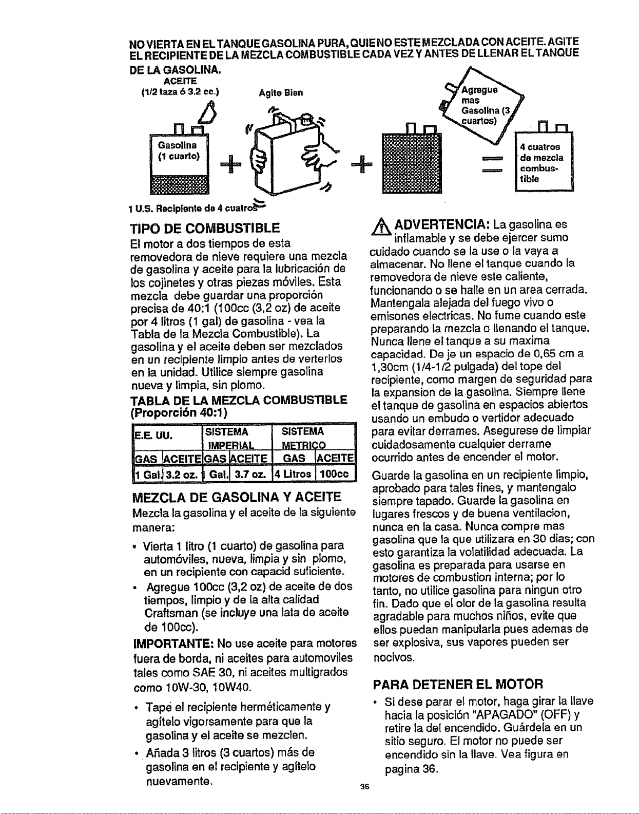
NO VIERTA EN EL TANQUE GASOLINA PURA, QUIE NO ESTE M EZCLADA CON ACEITE, AG1TE
EL REClPIENTE DE LA MEZCLA COMBUSTIBLE CADA VEZ Y ANTES DE LLENAR ELTANQUE
DE LA GASOLINA.
ACEITE
(1/2 taza 6 3.2 co,.)
1 U.S. RectpientQ da 4 cuatro_
Agite Bien
TIPO DE COMBUSTIBLE
El motor a dos tiempos de esta
removedora de nieve requiere una mezcla
de gasolina y aceite para la lubricaci6n de
los cojinetes y otras piezas m6vites. Esta
mezcla debe guardar una proporciSn
precisa de 40:1 (100cc (3,2 oz) de aceite
por 4 litros (1 gal) de gasolina - yea la
Tabla de la Mezcla Combustible). La
gasolina y el aceite deben ser mezclados
en un reclpiente limpio antes de verterfos
en la unidado Utilice siernpre gasolina
nueva y limpia, sin plomo.
TABLA DE LA MF_ZCLA COMBUSTIBLE
Proporci6n 40:1)
_.E'UU. " IslsTEMA ] SISTEMA I
.PER ALJ .E'rR CO U
=AS _CEITEIGAslAcBTEI GAS tACE!TE!
i Ga,l3:2o,. G,,.I o=.i,u,,o,I,o0oo/
M_CLA DE GASOLINA Y ACEITE
Mezcla la gasolina y el aceite de la siguiente
manera:
• Vierta 1 litro (1 cuarto) de gasolina para
autombviles, nueva, iimpia y sin plomo,
en un recipiente con eapacid sufioienteo
• Agregue 100cc (3,2 oz) de aceite de dos
tiempos, limpio y de la alta calidad
Craftsman (se incluye una lata de aceite
de 100cc).
IMPORTANTE: No use aceite para motores
fuera de borda, ni aceites para automoviles
tales como SAE 30, ni aceites multigrados
como 10W-30, 10W40.
• Tape el recipiente herm_ticamente y
ag|telo vigorsamente para que la
gasolina y el aceite se mezclen.
• Afiada 3 titros (3 cuartos) m&s de
gasolina en el recipiente y agiteto
nuevamente.
4.
uatros
ADVERTENCIA: La gasolina es
inflamable y se debe ejercer sumo
cuidado cuando se la use o la vaya a
atmacenar. No Ilene el tanque cuando ta
removedora de nieve este caliente,
funcionando o se halle en un area cerrada.
Mantengala alejada del fuego vivo o
emisones electricas. No fume cuando este
preparando la rnezcla o ltenando el tanque.
Nunca llene el tanque a su maxima
capacidad° De je un espacio de 0,65 cm a
1,30cm (1/4-1/2 pulgada) del tope det
recipiente, como margen de seguridad para
la expansion de la gasolina. Siempre llene
el tanque de gasolina en espacios abiertos
usando un embudo o vertidor adecuado
para evitar derrames. Asegurese de limpiar
cuidadosamente cualquier derrame
ocurddo antes de encender el motor.
Guarde la gasolina en un recipiente limpio,
aprobado para tales fines, y mantengalo
siempre tapado. Guarde la gasolina en
lugares frescos y de buena ventilacion,
nunca en la casao Nunca compre mas
gasolina que la que utilizara en 30 dias; con
esto garantiza la volatilidad adecuada. La
gasolina es preparada para usarse en
motores de combustion interna; por Io
tanto, no utilice gasolina para ningun otro
fin. Dado que el olor de la gasolina resulta
agradable para muchos niSos, evite que
ellos puedan rnanipularla pues ademas de
ser explosiva, sus vapores pueden set
nocivos.
36
PARA DETENER EL MOTOR
Si dese parar el motor, haga girar la Ilave
hacia la posici6n "APAGADO" (OFF) y
retire ta del encendido. Gu&rdela en un
sitio seguro. El motor no puede ser
encendido sin la Ilave.. Yea figura en
pagina 36.
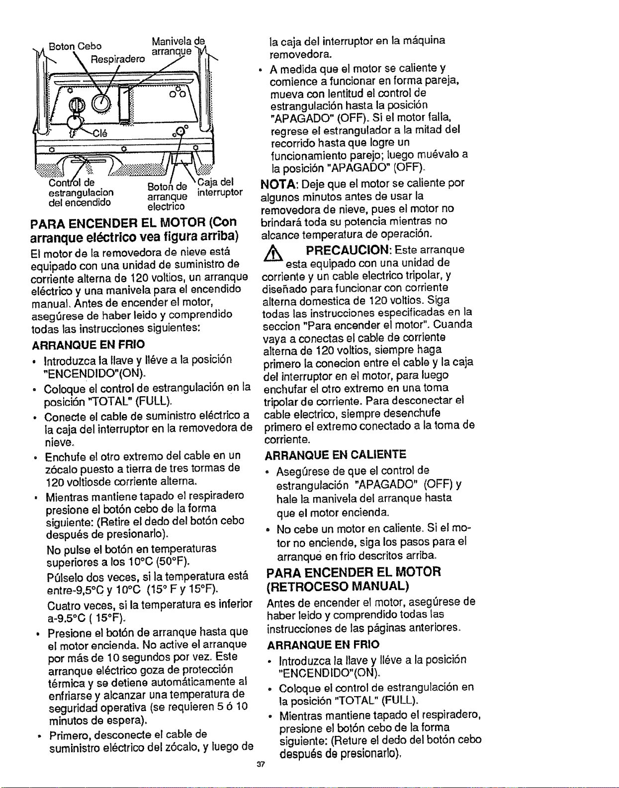
Boton Cebo Manivela
arrant
la caja del interruptor en la m&quina
removedora.
Jlde Boto_ del
estrangulacion arrangue interruptor
del encendido
electrrco
PARA ENCENDER EL MOTOR (Con
arranque el_Jctrlco vea figura arriba)
El motor de la removedora de nieve est_
equipado con una unidad de suministro de
corriente alterna de 120 voltios, un arranque
el6ctrico y una manivela pare el encendido
manual. Antes de encender el motor,
aseg'_rese de haber leido y comprendido
todas las instrucciones siguientes:
ARRANQUE EN FRIO
, lntroduzca la Ilave y Ii_ve ala posici6n
"ENCEND1DO"(ON),
, Coloque el control de estrangulacibn en la
posici6n "TOTAL" (FULL)_
• Conecte el cable de suministro el_ctrico a
ta caja del interruptor en la removedora de
nieve.
° Enchufe elotroextremo delcableen un
z6calo puesto a tierra de tres tormas de
120 voltiosde corriente alterna.
, Mientras mantiene tapado el respiradero
presione el bot6n cebo de la forma
siguiente: (Retire el dedo del bot6n cebo
despu_s de presionarlo).
No pulse el bot6n en temperaturas
superiores a los 10°C (50°F).
POlseto dos veces, sila temperature est&
entre-9,5°C y 10°C (15 ° F y !5°F).
Cuatro veces, si la temperatura es inferior
a-9.5°O (15°F).
, Presione el bot6n de arranque hasta que
el motor encienda. No active el arranque
por mds de 10 segundos pot vez. Este
arranque el_ctrico goza de protecci6n
t_rmica y se detiene autom&ticamente al
enfriarse y alcanzar una temperature de
seguridad operativa (se requieren 5 6 10
minutos de espera).
• Primero, desconecte el cable de
suministro el_ctrico del z6calo, y luego de
37
, A medida que e! motor se catiente y
comience a funcionar an forma pareja,
mueva con lentitud el control de
estrangulaci6n hasta la posici6n
"APAGADO" (OFF). Si el motor falla,
regrese e! estrangulador a fa m_ad del
recorrido hasta que Iogre un
funcionamiento parejo; luego mu_valo a
la posici6n "APAGADO" (OFF).
NOTA: Deje que el motor se caliente por
algunos minutos antes de usar la
removedora de nieve, pues el motor no
brindar& toda su potencia mientras no
alcance temperatura de operaci6n.
/_ PRECAUCION: Este
arranque
esta equipado con una unidad de
cordente y un cable electrico tripolar, y
diseSado pare funcionar con corriente
alterna domestica de 120 voltios. Siga
todas las instrucciones especificadas en la
seccion "Pare encender el motor". Cuanda
vaya a conectas el cable de corriente
alterna de 120 voltios, siempre haga
primero la conecion entre el cable y la caja
del interruptor en el motor, pare luego
enchufar el otto extremo en una tome
tripolar de corriente° Para desconectar el
cable electrico, siempre desenchufe
primero e! extremo conectado ala toma de
corriente.
ARRANQUE EN CALIENTE
, Aseg(Jrese de que el control de
estrangulaci6n "APAGADO" (OFF)y
hale la maniveta del arranque haste
que el motor encienda.
° No cebe un motor en caliente.. Si el mo-
tor no enciende, siga los pasos pare el
arranque en frio descritos arriba.
PARA ENCENDER EL MOTOR
(RETROCESO MANUAL)
Antes de encender el motor, aseg_rese de
haber leido y comprendido todas las
instrucciones de las p&ginas anterioreso
ARRANQUE EN FRIO
• Introduzca ta Ilave y Ii_ve ala posici6n
"ENOENDIDO"(ON)..
• Coloque el control de estrangulaci6n an
la pesict6n "TOTAL" (FULL).
• Mientras mantiene tapado el respiradero,
presione el bot6n cebo de la forma
siguiente: (Reture el dedo del bot6n cebo
despu_s de presionarlo),
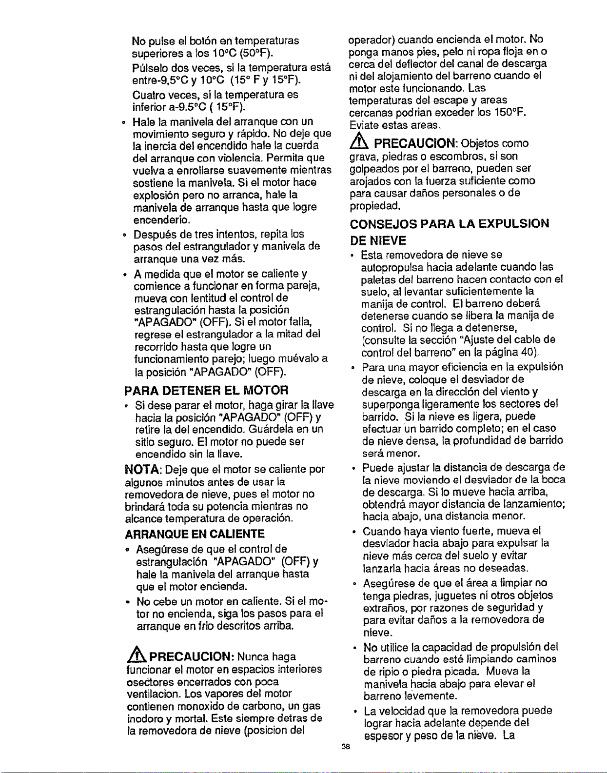
No pulse el bot6nen temperaturas
superioresa los 10°C(50°F)o
POlselodos veces,si la temperaturaest&
entre-9,5°Cy 10°G (15° F y 15°F).
Cuatroveces,si la temperaturaes
inferiora-9.5°C(15°F).
HalleHamanivetadel arranquecon un
movimientoseguro y r&pido.Nodeje que
la inerciadet encendidohalela cuerda
del arranquecon violenciaoPermitaque
vuelvaa enrollarsesuavementemientras
sostienela maniveta.Si el motorhace
explosi6nperono arranca,hale la
manivelade arranquehastaque logre
encenderioo
Despu_sde tres intentos,repitalos
pasosdel estranguladory manivelade
arranque una vez m&s.
A medida que el motor se catiente y
comience a funcionar en forma pareja,
mueva con lentitud el control de
estrangulaci6n hasta la posici6n
"APAGADO" (OFF). Si el motor fatla,
regrese el estrangulador a la mitad del
recorrido hasta que Hogreun
funcionamiento parejo; luego mu6vaHo a
la posici6n "APAGADO" (OFF).
PARA DETENER EL MOTOR
• Si dese parar el motor, haga girar la Iiave
hacia la posiciSn "APAGADO" (OFF) y
retire la del encendido. Gu&rdela en un
sitio seguro. El motor no puede ser
encendido sin la Ilave.
NOTA: Deje que el motor se caliente por
algunos minutos antes de usar la
removedora de nieve, pues el motor no
brindar& toda su potencia mientras no
alcance temperatura de operaci6no
ARRANQUE EN CALIENTE
. Aseg_rese de que et control de
estrangulaci6n "APAGADO" (OFF) y
hale la manivela del arranque basra
que el motor encienda.
. No cebe un motor en caliente. Si el mo-
tor no encienda, siga los pasos para et
arranque en frio descritos arriba.
A
PRECAUCION: Nunca haga
funcionar el motor en espacios interiores
oseCtores encerrados con poca
ventilaciono Los vapores del motor
contienen monoxido de carbono, un gas
inodoro y mortal. Este siempre detras de
la removedora de nieve (posicion del
operador) cuando encienda el motor. No
ponga manos pies, peto ni ropa floja en o
cerca del deflector del canal de descarga
ni del alojamiento del barreno cuando el
motor este 1uncionando. Las
temperaturas del escape y areas
cercanas podrian exceder los 150°F.
Eviate estas areas.
,/_ PREOAUClON: Objetos como
grava, piedras o escombros, si son
golpeados por el barreno, pueden ser
arojados con la tuerza suficiente como
para causar daSos personales o de
propiedad.
CONSEJOS PARA LA EXPULSION
DE NIEVE
• Esta removedora de nieve se
autopropulsa hacia adelante cuando las
patetas del barreno hacen contacto con el
suelo, al levantar suficientemente Ha
manija de control. El barreno deber&
detenerse cuando se tibera la manija de
control. Si no llega a detenerse,
(consulte la seccibn "Ajuste del cable de
control del barreno" en la p_,gina 40)°
o Para una mayor eficiencia en ta expulsibn
de nieve, coloque el desviador de
descarga en la direcci6n del viento y
superponga ligeramente los sectores det
barrido. Si la nieve es ligera, puede
efectuar un barrido completo; en el caso
de nieve densa, la profundidad de barrido
ser& menor.
• Puede ajustar la distancia de descarga de
la nieve moviendo e! desviador de la boca
de descarga_ Si 1o mueve hacia arriba,
obtendr& mayor distancia de lanzamiento;
hacia abajo, una distancia menor.
• Cuando haya viento fuerte, mueva el
desviador hacia abajo para expuisar la
nieve m&s cerca del suelo y evitar
tanzarla hacia _.reas no deseadas.
• Aseg6rese de que el &rea a timpiar no
tenga piedras, juguetes ni otros objetos
extraSos, p0r razones de seguridad y
para evitar dafios a la removedora de
nieve_
• No utilice la capacidad de propulsi6n del
barreno cuando est_ limpiando caminos
de ripio o piedra picada. Mueva la
manivela hacia abajo para elevar el
barreno levemente.
. La velocidad que la removedora puede
lograr hacia adetante depende det
espesor y peso de la nieve. La
98
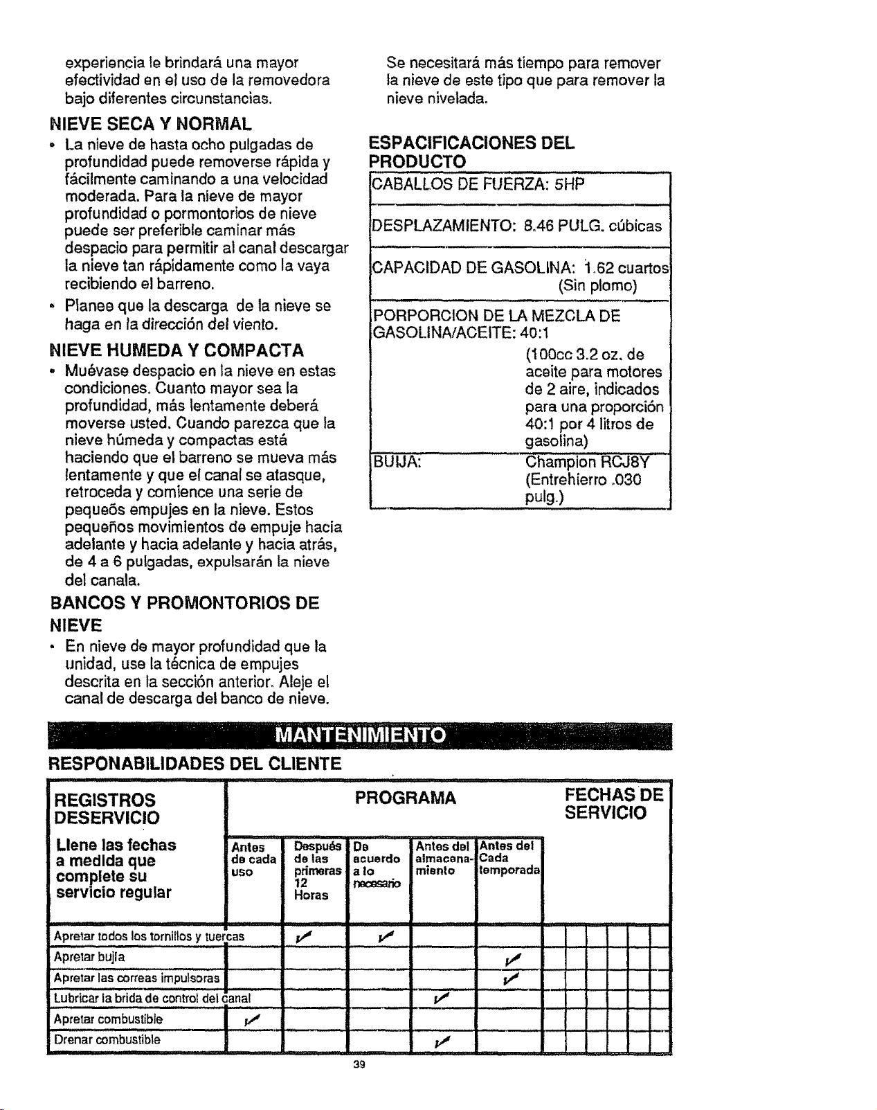
experiencia te brindar,_ una mayor
efectividad en el uso de la removedora
bajo diferentes circunstancias.
NIEVE SECA Y NORMAL
. La nieve de hasta ocho pulgadas de
profundidad puede removerse r&pida y
f&cilmente caminando a una velocidad
moderada. Para la nieve de mayor
profundidad o pormontofios de nieve
puede ser preferible caminar m_.s
despacio para permitir al canal descargar
la nieve tan r&pidamente como la vaya
recibiendo el barreno.
, Planee que la descarga de la nieve se
haga en ta direccf6n del viento.
NIEVE HUMEDA Y COMPACTA
. Mu_vase despacio en la nieve en estas
condicioneso Cuanto mayor sea la
profundidad, m&s lentamente deber&
moverse usted, Cuando parezca que la
nieve hOmeda y compactas est&
haciendo que el barreno se mueva m&s
lentamente y que el canal se atasque,
retroceda y comience una serie de
pequeSs empujes en la nieve. Estos
pequefios movimientos de empuje hacia
adelante y hacia adelante y hacia atr&s,
de 4 a 6 putgadas, expulsar&n la nieve
del canala.
BANCOS Y PROMONTORIOS DE
N1EVE
• En nieve de mayor profundidad que la
unidad, use la t_cnica de empujes
descrita en ta secci6n anterior. Aleje el
canal de descarga del banco de nieve.
Se necesitar_ m&s tiempo para remover
la nieve de este tipo que para remover la
nieve nivelada.
ESPACIFICACIONES DEL
PRODUCTO
i, .... ., ,,,, i . ..m,l..,
CABALLOS DE FUERZA: 5HP
DESPLAZAMIENTO: 8_46 PULG. cObicas
CAPACIDAD DE GASOLINA: :1,62 cuartos
(Sin plomo)
PORPORCION DE LA MEZCLA DE
GASOLINA/ACEITE: 4o:1
BUUA:
(100cc 3.2 oz. de
aceite para motores
de 2 aire, indicados
para una proporcibn
40:1 por 4 litros de
gasolina)
Champion R_8Y
(Entrehierro °030
pulg.)
RESPONABILIDADES DEL CLIENTE
÷
:.:.. : ..............
REGISTROS
DESERVICIO
Llene las fechas
a medlda que
complete su
servlcio regular
Antes !
de cada
uso
Apretar todos los tornillos y tuercas
Aprelar bujla
Apretar las correas impulsoras
Lubricar la bridede contro!del canal
Apretarcombustible v"
Drenarcombustible
PROGRAMA
Despu_s
de ias
primeras
12
Horas
i,iii
DD
acuerdo
a Io
nacesario
v"
ii ............ iii
Antes del Antes del
almacena- Carla
mianto temporada
v"
v"
FECHAS DE
SERVIClO
: , :,,
. _.
39
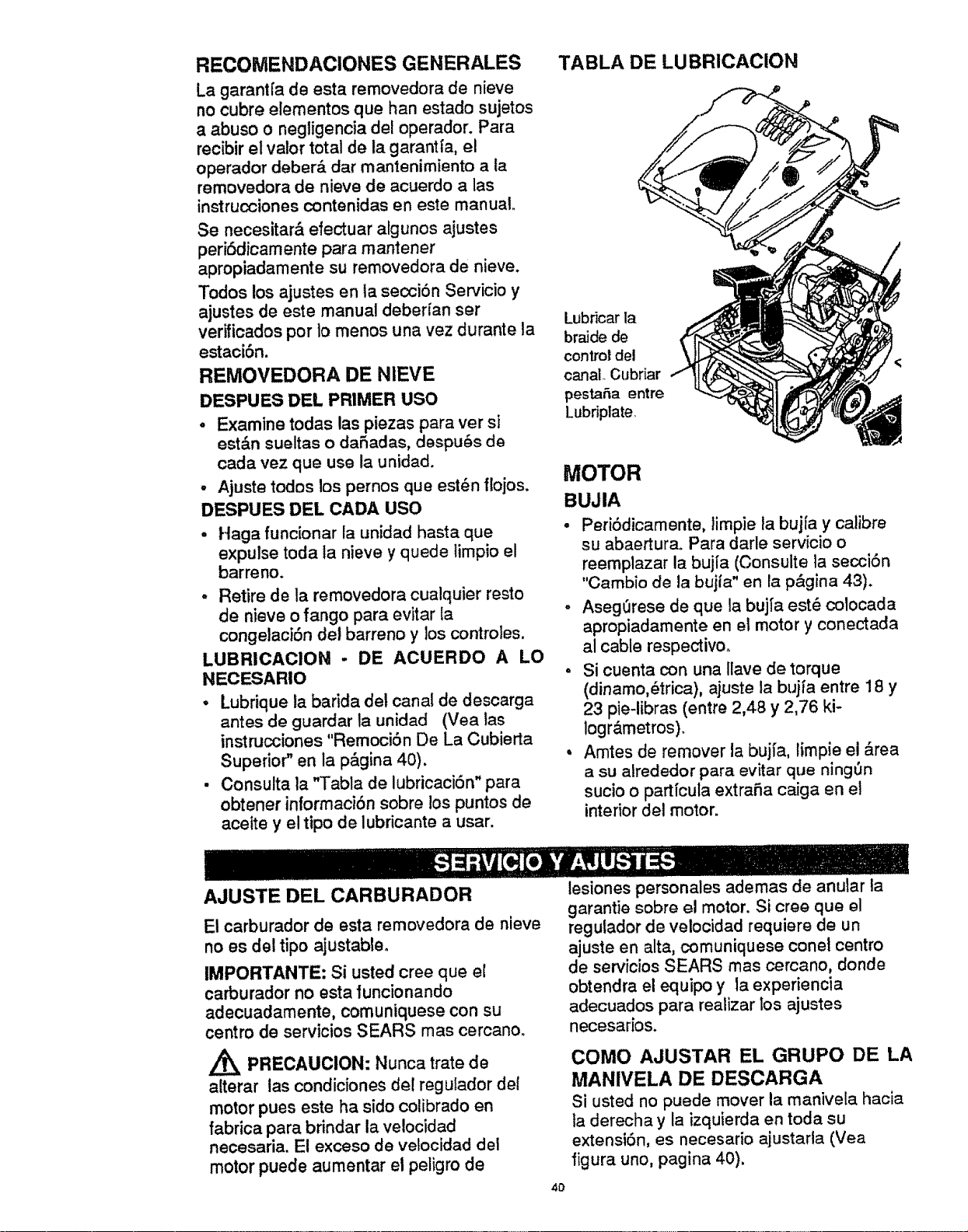
RECOMENDACIONES GENERALES
La garantfa de esta removedora de nieve
no cubre elementos que ban estado sujetos
a abuso o negligencia del operador. Para
recibir el valor total de la garantla, el
operador deber_, dar mantenimiento a ta
removedora de nieve de acuerdo a las
instrucciones contenidas en este manual.
Se necesitar_, efectuar algunos ajustes
perJ6dJcamer_tepara mantener
apropiadamente su removedora de nieve.
Todos los ajustes en ta seccibn Servicio y
ajustes de este manual debefian ser
verificados por to menos una vez durante ta
estaci6n.
REMOVEDORA DE NIEVE
DESPUES DEL PRIMER USO
, Examine todas las piezas para ver si
est&n sueltas o daSadas, despu6s de
cada vez que use .ta unidad.
- Ajuste todos los pernos que est_n flojos.
DESPUES DEL CADA USO
. Haga funcionar la unidad hasta que
expulse toda ta nieve y quede limpio el
barreno.
° Retire de la removedora cualquier resto
de nieve o fango para evitar ta
concje_aciSn de_barreno y los contro_es.
LUBRICACION - DE ACUERDO A LO
NECESARIO
° Lubrique la barida det canal de descarga
antes de guardar la unidad (Vea tas
instrucciones "Remoci6n De La Cubierta
Superior" en la p&gina 40).
• Consulta la "Tabla de lubricaci6n" para
obtener informaciSn sobre los puntos de
aceite y el tipo de lubricante a usar.
TABLA DE LUBRICACION
Lubdcar la
braide de
control del
canal. Cubriar
pestaSa entre
Lubriplate.
MOTOR
BUJIA
- Peri6dicamente, limpie ta bujfa y calibre
su abaertura. Para darle servicio o
reemplazar la bujfa (Consulte la secci6n
"Cambio de la bujfa" en la p&gina 43).
- AsegOrese de que la buj_'a est_ cotocada
apropiadamente en el motor y conectada
al cable respectivo.
o Si cuenta con una llave de torque
(dinamo,_trica), ajuste la bujfa entre t 8 y
23 pie-libras (entre 2,48 y 2,76 ki-
logr&metros).
, Amtes de remover la bujfa, limpie el &tea
a su alrededor para evitar que ning_n
sucio o partfcuta extraSa caiga en el
interior del motor.
AJUSTE DEL CARBURADOR
E! carburador de esta removedora de nieve
no es del tipo ajustable.
IMPORTANTE: Si usted cree queef
carburador no esta funcionando
adecuadamente, comuniquese con su
centro de servicios SEARS mas cercano.
A
PRECAUCION: Nunca trate de
alterar las condiciones del regulador de!
motor pues este ha sido colibrado en
fabrica para brindar la ve!ocidad
necesada. El exceso de velocidad del
motor puede aumentar el peligro de
40
lesiones personales ademas de anular la
garantie sobre el motor. Si cree qua el
regulador de veiocidad requiere de un
ajuste en alta, comuniquese ¢onet centro
de servicios SEARS mas cercano, donde
obtendra el equipo y la experiencia
adecuados para realizar los ajustes
necesar[os.
COMO AJUSTAR EL GRUPO DE LA
MANIVELA DE DESCARGA
Si usted no puede mover la manivela hacia
la derecha y la izquierda en toda su
extensi6n, es necesario ajustarla (Vea
figura uno, pagina 40).
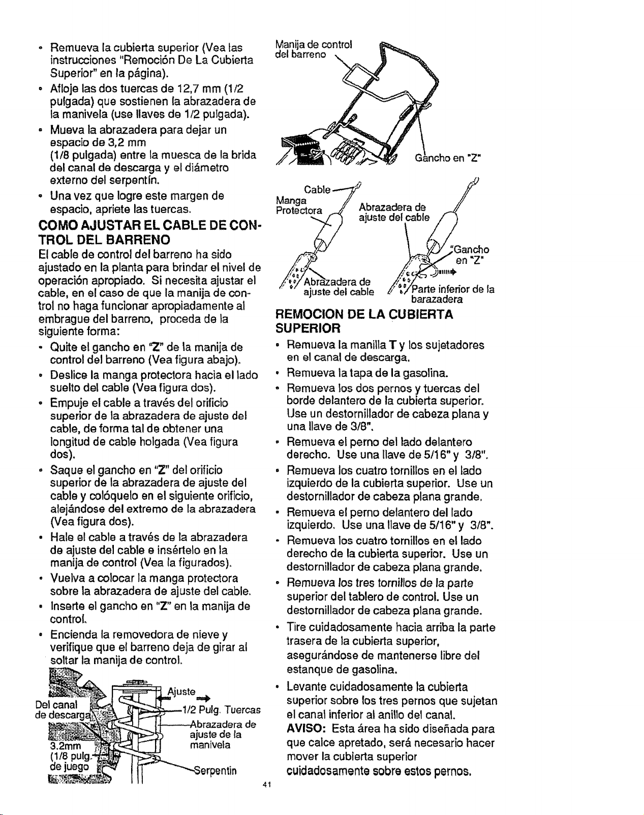
- Remuevala cubiertasuperior(Veatas
instrucciones"Remoci6nDe La Cubierta
Superior"en ta p&gina).
• Aflojelas dos tuercasde 12,7 rnm (1/2
pulgada)quesostienenla abrazaderade
ta manivela(use Ilavesde 1/2pulgada).
- Muevata abrazaderapara dejarun
espaciode 3,2 mm
(1/8pulgada)entre lamuescade la brida
del canalde descargay el di&metro
externodel serpentin.
o Unavez que logreeste margende
espacio,aprietelastuercas,
COMO AJUSTAR EL CABLE DE CON-
TROL DEL BARRENO
E! cable de control del barreno ha sido
ajustado en la planta para brindar el nivel de
operaci6n apropiado. Si necesita ajustar el
cable, en el caso de que la manija de con-
trol no haga funcionar apropiadamente a!
embrague del barreno, proceda de ta
siguiente forma:
- Quite el gancho en '_Z" de ta manija de
control del barreno (Vea figura abajo)o
° Deslice la mango protectora hacia el lado
suelto del cable (Vea figura dos).
° Empuje el cable a trav6s del orificio
superior de la abrazadera de ajuste del
cable, de forma tal de obtener una
longitud de cable holgada (Vea figura
dos).
° Saque el gancho en "Z" del orificio
superior de la abrazadera de ajuste del
cable y cot6quelo en el siguiente orificio,
alej&ndose clel extremo de la abrazadera
(Vea figura dos).
° Hale el cable a trav6s de la abrazadera
de ajuste del cable e ins_rtelo en la
manija de control (Yea ta figurados)°
• Vuetva a colocar la mango protectora
sobre la abrazadera de ajuste del cable.
• Inserte el gancho en "Z" en la manija de
control.
• Encienda ta removedora de nieve y
verffique que e! barreno deja de girar al
soltar la manija de control.
Del canal Pulg Tuercas
de
de
ajuste de la
3.2mm manivela
(1/8 pulg:
oe juego "p_ntin
41
Manija de control
del barreno
en "Z"
Mango
Prnt_r_tnra / Abrazadera de
........ -L_F'_ ajuste del cable /"
_V/" Abr_zadera de _YParte inferior d,
ajuste del cable _/P_a2 .f_aOr de la
REMOCION DE LA CUBIERTA
SUPERIOR
° Remueva la manJlla T y los sujetadores
en el canal de descarga.
• Remueva la tapa de la gasolina.
- Remueva los dos pernos y tuercas del
borde delantero de la cubierta superior.
Use un destornillador de cabeza piano y
una Uave de 3/8".
- Remueva el perno dei lado delantero
derecho. Use una [lave de 5/16" y 3/8'L
= Rernueva los cuatro tornillos en el tado
izquierdo de la cubierta superior. Use un
destornillador de cabeza piano grande.
° Remueva et perno delantero del lado
izquierdo. Use una Ilave de 5/16"y 3/8".
- Remueva los cuatro tomiltos en el lado
derecho de la cubierta superior. Use un
destornillador de cabeza plana grande.
• Remueva los tres tomillos de la porte
superior del tablero de control. Usa un
destornillador de cabeza plana grande.
• Tire cuidadosamente hacia arriba la parte
trasera de la cubierta superior,
asegur_,ndose de mantenerse libre del
estanque de gasolina.
• Levante cuidadosamente la cubierta
superior sobre los tres pernos que sujetan
el canal inferior at anillo de1 canal.
AVISO: Esta &rea ha sido diseSada para
qua calce apretado, ser& necesario hacer
mover la cubierta superior
_uidadosamente sobreestos pernos,
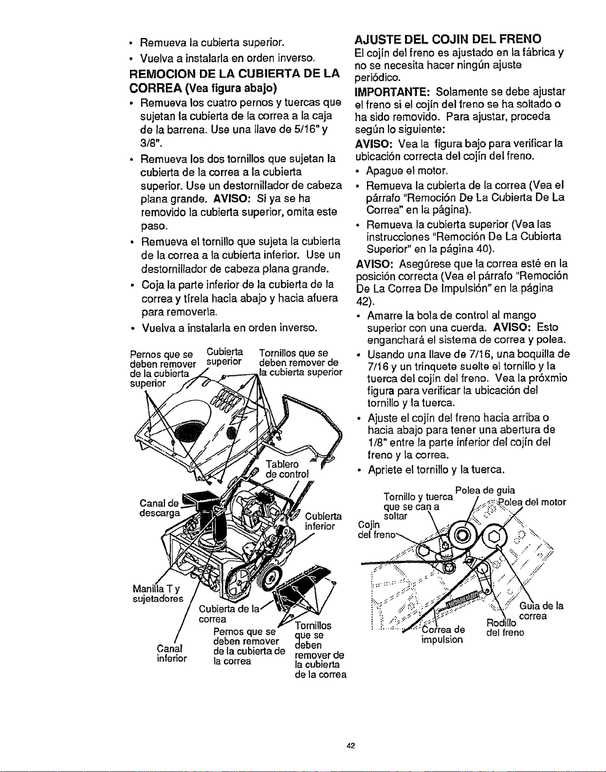
° Remueva la cubierta superior.
° Vuelva a instalarla en orden inverse,
REMOCION DE LA CUBIERTA DE LA
CORREA (Yea figura abajo)
• Remueva los cuatro pemos y tuercas que
sujetan la cubierta de la correa a la caja
de la barrenao Use una llave de 5/16" y
3/8".
° Remueva los dos torniltos que sujetan la
cubierta de la correa a la cubierta
superior. Use un destornillador de cabeza
plana grande. AVISO: Si ya se ha
removido la cubierta superior, omita este
paso.
• Remueva el tornilto que sujeta la cubierta
de la correa a ta cubierta inferior, Use un
destornillador de cabeza plana grande,
° Coja la parte inferior de la cubierta de la
correa y tirela hacia abajo y hacia afuera
para removeda.
• Vuelva a instalarla en orden inverse.
Pernos que se Cubierta
deben remover superior
de la ¢ubierta
supedor
Tornillos que se
deben remover de
la cubierta superior
Canal de
descarga
Oubierta
inferior
Manil'_aT y
sujetadores
Canal
inferior
Cubierta de
correa
Pernos que se
deben remover
de la cubierta de
la correa
ue se
eben
remover de
la cubierta
de la correa
AJUSTE DEL COJIN DEL FRENO
El cojin del freno es ajustado en ta f&brica y
no so necesita hacer ningSn ajuste
periSdico,
IMPORTANTE: Solamente se debe ajustar
el freno si el cojin del Irene se ha sottado o
ha side removido. Para ajustar, proceda
seg_n Io siguiente:
AMISO: Vea la figura bajo para verificar la
ubicaciSn correcta del cojin del freno.
° Apague et motor,
• Remueva ia cubierta de la correa (Yea el
p&rrafo "Remoci6n De La Cubierta De La
Correa" en la p_.gina)_
- Remueva la cubierta superior (Vea las
instrucciones "Remoci6n De La Cubierta
Superior" en ta p&gina 40).
AVISO: Aseg_rese que la correa est6 en la
posici6n correcta (Vea el p_,rrafo "RemociSn
De La Correa De Impulsi6n" en la p_gina
42),
. Amarre la bola de control at mango
superior con una cuerda, AVISO: Esto
enganchar& el sistema de correa y polea.
• Usando una Ilave de 7/16, una boquilla de
7/16 y un trinque_e suelte el torniilo y la
tuerca del coj[n det freno. Vea la pr6xmio
figura para verificar la ubicaci6n det
tornillo y la tuerca.
- Ajuste el cojin del freno hacia arriba o
hacia abajo para tener una abertura de
1/8" entre la parte inferior del coj{n de!
freno y la correa.
. Apriete el tornillo y la tuerca,
Oojin
del
Tornillo y tuerca Polea de guia
'olea del motor
qoU_ta_ecan a
.,, /%,
i
impulsion
de la
Roc I11ocorrea
del freno
42
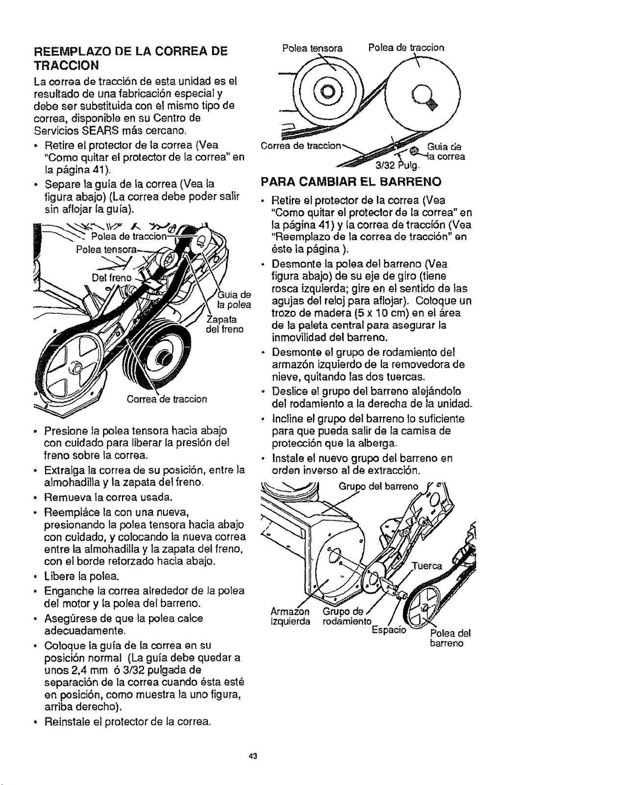
REEMPLAZO DE LA CORREA DE
TRACCION
La correa de tracci6n de esta unidad es el
resuttado de una fabricaci6n especial y
debeser substituida con el mismo tipo de
correa, disponible en su Centro de
Servicios SEARS mQs cercano.
o Retire el protector de la correa (Vea
"Como quitar et protector de la correa" en
la p&gina 41 )°
. Separe la guia de la correa (Vea la
figura abajo) (La correa debe poder salir
sin aflojar {a gu ia).
,uia de
la polea
Zapata
del treno
Corre_ traccion
It
o
g
o
Presione ta polea tensora hacia abajo
con cuidado para liberar la presiSn det
freno sobre la correa,
Extratga la correa de su posici6n, entre la
almohadilla y ta zapata det freno.
Remueva la correa usada.
Reempt&ce la con una nueva,
presionando ta polea tensora hacia abajo
con cuidado, y colocando la nueva correa
entre ta almohadilla y la zapata dei freno,
con el borde reforzado hacia abajo.
Libere la polea.
Enganche la correa atrededor de la polea
del motor y la polea det barreno.
Aseg0rese de qua ta polea calce
adeouadamente,
• Co!oque la guia de la correa an su
posici6n normal (La guia debe quedar a
unos 2,4 mm 5 3/32 pulgada de
separaci6n de la correa cuando 6sta est_
en posici6n, como muestra la uno figura,
arriba derecho).
• Reinstale el protector de la correao
Polea tensora Polea de traccion
Correa de Guia de
correa
'uqg.
PARA CAMBIAR EL BARRENO
• Retire el protector de la correa (Vea
"Como quitar el protector de Za correa" en
la p&gina 41 ) y la correa de tracciSn (Vea
"Reemplazo de la correa de tracci6n" en
_ste la p_.gina ).
- Desmonte ta polea del barreno (Vea
figura abajo) de su eje de giro (tiene
rosca izquierda; gire en el sentido de tas
agujas del reloj para aflojar)° Coloque un
trozo de madera (5 x 10 cm) en et &rea
de !a paleta central para asegurar la
inmovilidad del barreno.
- Desmonte el grupo de rodamiento del
armaz6n izquierdo de la removedora de
nieve, quitando tas dos tuercaso
• Deslice et grupo del barreno alej&ndo[o
del rodamiento a la derecha de la unidad.
• tncline el grupo del barreno 1o suficiente
para que pueda satir de la camisa de
protecci6n qua la alberga.
. lnstale et nuevo grupo del barreno en
orden inverso al de extracci6n.
del barreno
Arma_on
izquierda
Polea del
barreno
43
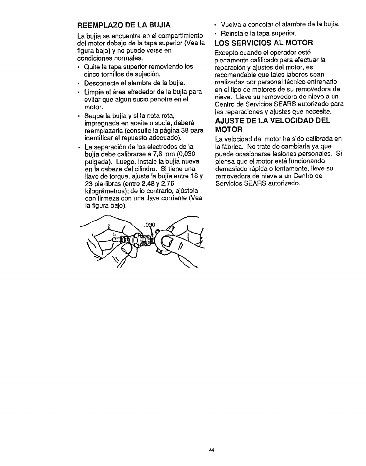
REEMPLAZO DE LA BUJIA
La bujia se encuentra en el compartimiento
del motor dobajo de la tapa superior (Vea la
figura bajo) y no puede verse en
condiciones normateso
, Quite ta tapa superior removiendo los
cinco tornillos de sujeciSn.
• Desconecte el alambre de ia bujfao
o Limpie el _,rea alrededor de la bujl'a para
evitar que alg_n sucio penetre en el
motor.
• Saque la bujia y si la nora rota,
impregnada en aceite o sucia, deber,_
reemplazarta (consulte la p,_gina 38 para
identificar el repuesto adecuado).
o La separaciSn de los electrodes de la
bujia debe calibrarse a 7,6 mrn (0,030
putgada). Luego, instale la bujia nueva
en la cabeza del cilindro. Si tiene una
tlave de torque, ajuste ta bujfa entre 18 y
23 pie-libras (entre 2,48 y 2,76
kilogr&metros); de Io contrario, aj_stela
con firmeza con una tlave corriente (Yea
la figura bajo).
• Vuelva a conectar el alambre de la bujia.
• Reinstate fa tapa superior.
LOS SERVIClOS AL MOTOR
Excepto cuando e] operador est6
plenamente calificado para efectuar la
reparaciSn y ajustes del motor, es
recomendable que tales labores sean
realizadas per personal t_cnico entrenado
en el ripe de motores de su removedora de
nieve. Lleve su removedora de nieve a un
Centre de Servicios SEARS autorizado para
las reparaciones y ajustes que necesite.
AJUSTE DE LA VELOCIDAD DEL
MOTOR
La velocidad del motor ha side calibrada en
la f&brica. No trate de cambiarla ya que
puede ocasionarse lesiones personales. Si
piensa que el motor est& funcionando
demasiado r_pida o lentamente, lleve su
removedora de nieve a un Centre de
Servicios SEARS autorizado.
44
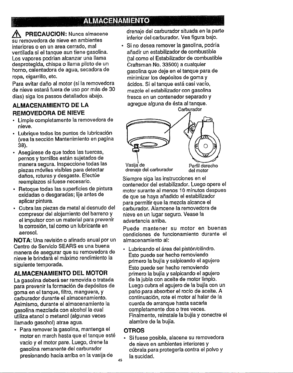
Z_ PRECAUCION: Nunca almacene
su removeclora de nieve en ambientes
interiores o en un area cerrado, mal
ventilada si el tanque aun tiene gasolina.
Los vapores podrian alcanzar una llama
desprotegida, chispa o llama piloto de un
homo, calentadora de agua, secadora de
ropa, cigarrillo, etc.
Para evitar daSo al motor (si la removedora
de nieve estar& fuera de uso por m&s de 30
dias) siga los passos detallados abajo.
ALMACENAMIENTO DE LA
REMOVEDORA DE NIEVE
• Limpie completamente la removedora de
nieve.
• Lubrique todos los puntos de lubricaci6n
(yea la secci6n Mantenimiento en pagina
3a).
, Aseg_rese de que todos tas tuercas,
pernos y torniltos est&n sujetados de
manera segura. Inspeccione todas las
piezas mSviles visibles para detectar
dafios, roturas y desgaste. Efect=3e
reemplazos si fuese necesario.
• Retoque todas las superficies de pintura
oxidadas o desgaradas; lije antes de
aplicar pintura_
• Cubra tas piezas de metal al desnudo del
compresor de! alojamiento de! barreno y
e! impulsor con un material para prevemr
la corrosiSn, tal corno un lubricante en
aerosol.
NOTA: Una revisiSn o afinado anual por un
Centro de Servicio SEARS es una buena
manera de asegurar que su removedora de
nieve le brindar& el m,_ximo rendimiento la
siguiente temporada.
ALMACENAMIENTO DEL MOTOR
La gasolina deber& ser removida o tratada
para prevenir la formaci6n de depSsitos de
goma en el tanque, filtro, manguera, y
carburador durante el atmacenamiento.
Asimismo, durante el almacenamiento la
gasolina mezclada con alcohol la cual
utiliza etanol o metanol (algunas veces
tlamado gasohol) atrae agua,
. Para remover la gasolina, mantenga el
motor en march hasta que e! tanque est6
vacio y el motor pare. Luego, drene la
gasolina remanente del carburador
presionando hacia arriba en la vasija de
45
drenaje del carburador situada en la parte
inferior del carburador. Vea figura bajo.
Si no desea remover ta gasolina, podria
afiadir un estabilizador de combustible
(tal como el Estabilizador de combustible
Craftsman No. 33500) a cualquier
gasolina que deje en el tanque para de
minimizar los dep6sitos de goma y
&cidos. Si el tanque est& casi vacio,
mezcle el estabitizador con gasolina
fresca en un contenedor separado y
agregue alguna de _sta al tanqueo
Carburador
Vasij de Perfil derecho
drenaje del carburador del motor
Siempre siga las instrucciones en el
contenedor de! estabilizador. Luego opere el
motor surante al menos 10 minutos despues
de que se haya afiadido el estabilizador
para permitir que ta mezcla alcance et
carburador. Alamcene la removedora de
nieve en un lugar seguro. Vease la
advertencia arriba.
Puede mantener su motor en buenas
condiciones de funcionamiento durante el
almacenamiento al:
Lubricando el &rea del pist6n/cilindro.
Esto puede ser hecho removiendo
primero la bujia y salpicando el agujero
Esto puede ser hecho removiendo
primero ta bujia y salpicando el agujero
de la jubla con aceite de motor timpio.
Luego cubra el agujero de la buj[a con un
pa_o para absorber el rocfo de aceite. A
continuaciSn, rote et motor al halar de {a
cuerda de arranque hasta sacarla
completamente dos o tres veces.
Finatmente, reinstale la bujia y conectre el
alambre de la bujfa,
OTROS
, Si fuese posible, atacene su removedora
de nieve en ambientes interiores y
cObrala para protegerla contra el polvo y
la sucidad.
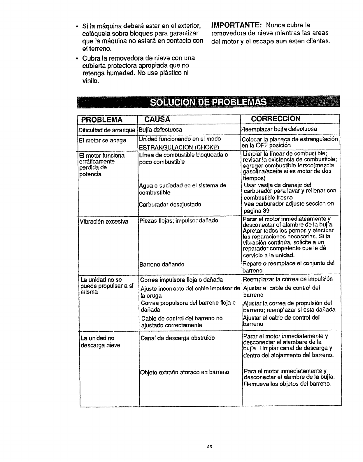
Si la m&quina deber& estar en el exterior,
colSquela sobre bloques para garantizar
que ia rn&quina no estar_, en contacto con
el terreno.
Cubra la rernovedora de nieve con una
cubierta protectora apropiada que no
retenga humedad. No use pl_stico ni
vinilo.
IMPORTANTE: Nunca cubra la
removedora de nieve mientras las areas
de] motor y el escape aun esten clientes.
PROBLEMA CAUSA
.....,,,,,
Dificultad de arranque
E'i motor' se 'aPaga
El motor funciona
err&ticamente
:erdida de
potencia
CORRECCION
Bujia defectuosa Reemplazar bujfa defectuosa
Unidad funcionando en el modo Colocar la planaca de estrangulaciSn
ESTRANGULAClON (CHOKE) en la OFF posici6n
L(nea de combustible bfoqueada o Limpiar la linear de combuStibiei ........
poco combustible revtsar ia existencia de combustible;
agregar combustible fersco(mezcla
gasolina/aceite si es motor de dos
tiempos)
Agua o suciedad en el sistema de Usar vasija de drenaje del
combustible carburador para lavar y rellenar con
combustible fresco
Carburador desajustado Vea carburador adjuste seccion on
pagina 39
Piezas flojas; impuiSor daSado Parar el motor inmediateamente y
desconectar el alambre de la bujfa,,
Apretar todos los pemos y efectuar
_as reparaciones necesarias. Si la
vibraciSn continua, solidte a un
reparador competente que le d6
servicio a la unidado
Barreno dafiando Repare o reemplace el conjunto de!
barreno
..... .,,, , ....... ...........
........ , :.=
Correa impulsora floja o daS.ada Reemplazar la correa de imputsi6n
Ajuste incorrecto det cable impulsor de Ajustar et cable de control det
la oruga barreno
Correa propulsora del barreno floja o Ajustar la oorrea de propulsi6n del
daSada barreno; reemptazar siesta daSada
Cable de control del barreno no Ajustar el cable de control del
ajustado correctamente barreno
Canal de descarga obstruido
Objeto extraSo atorado en barreno
Vibracibn excesiva
La unidad no se
puede propulsar a sl
mlsma
La unidad no
descarga nieve
=afar el motor inmediatemente y
desconectar el atambare de la
bujl'a,, Limpiar canal de descarga y
dentro del alojamiento del barreno.
Para el motor inmediatamente y
desconectar et atambre de la bujla.
Remueva los objetos del barreno,
46

47
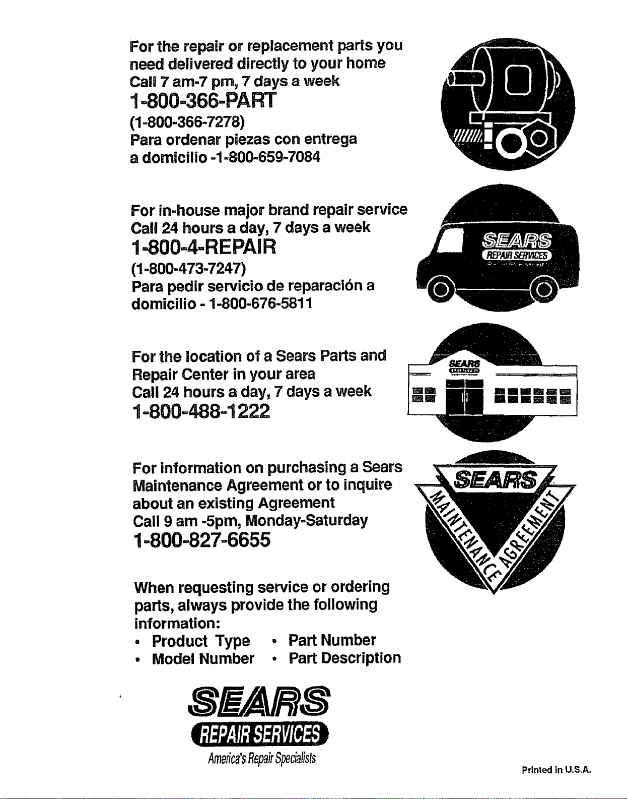
For the repair or replacement parts you
need delivered directly to your home
Carl 7 am-7 pro, 7 days a week
1-800=366=PART
(1-800-366-7278)
Para ordenar piezas con entrega
a domicilio-1.800=659-7084
For in-house major brand repair service
Call 24 hours a day, 7 days a week
1-800=4=REPAIR
(1-800-473-7247)
Para pedir servicio de reparacidn a
domicilio - 1-80(,-676-5811
For the location of a Sears Parts and
Repair Center in your area
Call 24 hours a day, 7 days a week
1=800=488=1222
ImllllNIm
=,,,,,=,=m
For information on purchasing a Sears
Maintenance Agreement or to inquire
about an existing Agreement
Call 9 am -5pm, Monday-Saturday
1-800-827=6655
When requesting service or ordering
parts, always provide the following
information:
• Product Type ° Part Number
• Model Number • Part Description
Amefica'sRep#Specialists
Printed in U.S.A.