Loading ...
Loading ...
Loading ...
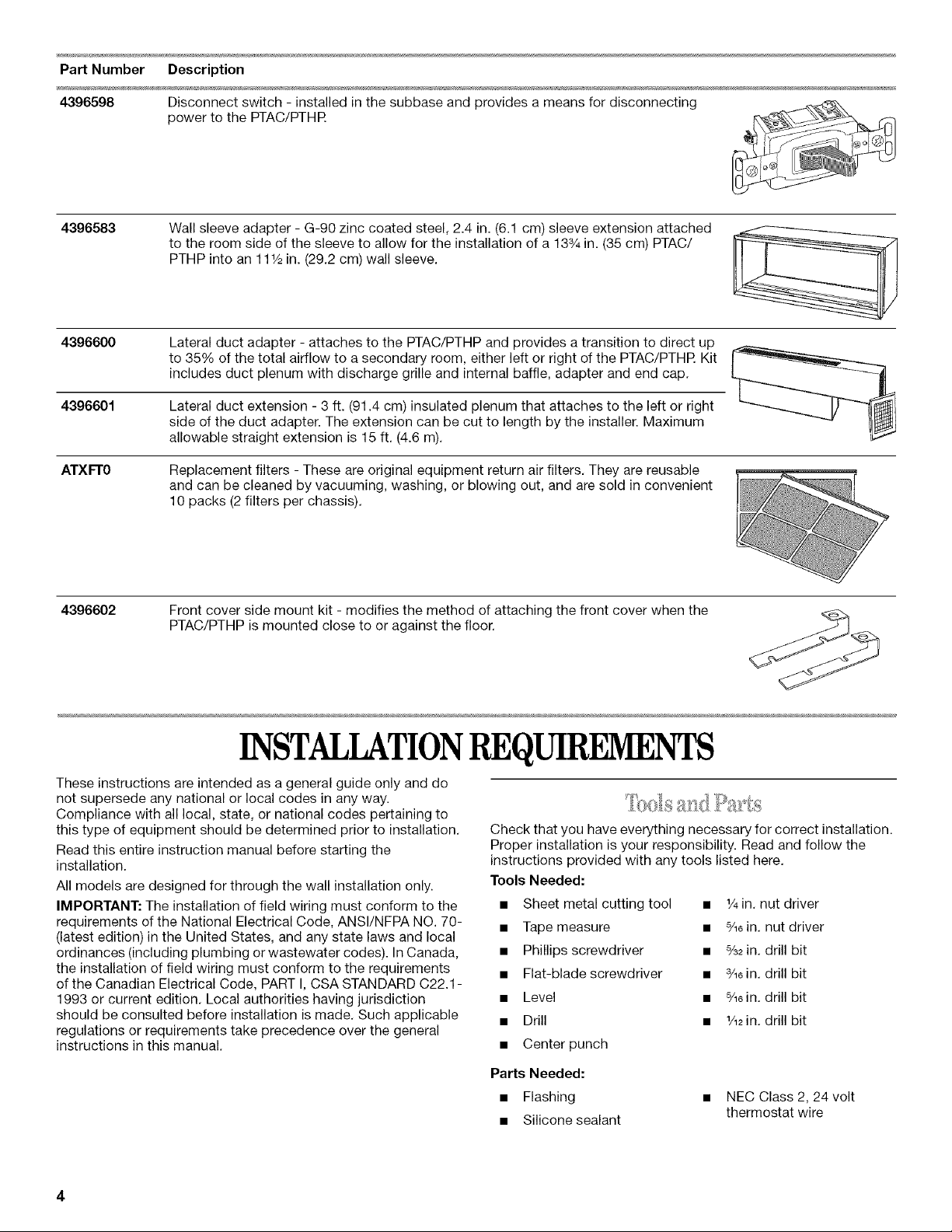
Part Number Description
4396598 Disconnect switch - installed in the subbase and provides a means for disconnecting
power to the PTAC/PTHR
4396583
Wall sleeve adapter - G-90 zinc coated steel, 2.4 in. (6.1 cm) sleeve extension attached
to the room side of the sleeve to allow for the installation of a 133/4in. (35 cm) PTAC/
PTHP into an 11 _/2in. (29.2 cm) wall sleeve.
4396600 Lateral duct adapter - attaches to the PTAC/PTHP and provides a transition to direct up
to 35% of the total airflow to a secondary room, either left or right of the PTAC/PTHR Kit
includes duct plenum with discharge grille and internal baffle, adapter and end cap.
4396601 Lateral duct extension - 3 ft. (91.4 cm) insulated plenum that attaches to the left or right
side of the duct adapter. The extension can be cut to length by the installer. Maximum
allowable straight extension is 15 ft. (4.6 m).
ATXFT0 Replacement filters - These are original equipment return air filters. They are reusable
and can be cleaned by vacuuming, washing, or blowing out, and are sold in convenient
10 packs (2 filters per chassis).
4_6_2
Front cover side mount kit - modifies the method of attaching the front cover when the
PTAC/PTHP is mounted close to or against the floor.
INSTALLATIONREQUIREMENTS
These instructions are intended as a general guide only and do
not supersede any national or local codes in any way.
Compliance with all local, state, or national codes pertaining to
this type of equipment should be determined prior to installation.
Read this entire instruction manual before starting the
installation.
All models are designed for through the wall installation only.
IMPORTANT: The installation of field wiring must conform to the
requirements of the National Electrical Code, ANSI/NFPA NO. 70-
(latest edition) in the United States, and any state laws and local
ordinances (including plumbing or wastewater codes). In Canada,
the installation of field wiring must conform to the requirements
of the Canadian Electrical Code, PART I, CSA STANDARD C22.1 -
1993 or current edition. Local authorities having jurisdiction
should be consulted before installation is made. Such applicable
regulations or requirements take precedence over the general
instructions in this manual.
Check that you have everything necessary for correct installation.
Proper installation is your responsibility. Read and follow the
instructions provided with any tools listed here.
Tools Needed:
• Sheet metal cutting tool
• Tape measure
• Phillips screwdriver
• Flat-blade screwdriver
• Level
• Drill
• Center punch
• V4in. nut driver
• %6in. nut driver
• %2in. drill bit
• 3/_6in. drill bit
• ¾ein. drill bit
• _/_in. drill bit
Parts Needed:
• Flashing • NEC Class 2, 24volt
thermostat wire
• Silicone sealant
Loading ...
Loading ...
Loading ...