Loading ...
Loading ...
Loading ...
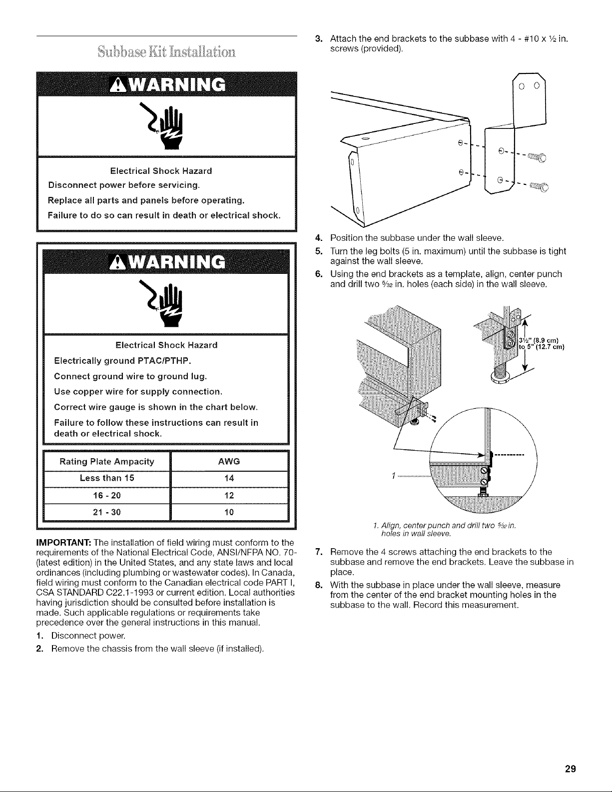
3. Attach the end brackets to the subbase with 4 - #10 x 1/2in.
screws (provided).
Electrical Shock Hazard
Disconnect power before servicing.
Replace all parts and panels before operating.
Failure to do so can result in death or electrical shock.
Electrical Shock Hazard
Electrically ground PTAC/PTHP.
Connect ground wire to ground lug.
Use copper wire for supply connection.
Correct wire gauge is shown in the chart below.
Failure to follow these instructions can result in
death or electrical shock.
Rating Plate Ampacity
Less than 15
16 = 20
21 - 30
AWG
14
12
10
IMPORTANT: The installation of field wiring must conform to the
requirements of the National Electrical Code, ANSI/NFPA NO. 70-
(latest edition) in the United States, and any state laws and local
ordinances (including plumbing or wastewater codes). In Canada,
field wiring must conform to the Canadian electrical code PART I,
CSA STANDARD C22.1-1993 or current edition. Local authorities
having jurisdiction should be consulted before installation is
made. Such applicable regulations or requirements take
precedence over the general instructions in this manual.
1. Disconnect power.
2. Remove the chassis from the wall sleeve (if installed).
4. Position the subbase under the wall sleeve.
5. Turn the leg bolts (5 in. maximum) until the subbase is tight
against the wall sleeve.
6. Using the end brackets as a template, align, center punch
and drill two %2 in. holes (each side) in the wall sleeve.
@,,(8.9 cm)
(12 7 cm)
!. Align, centerpunch and drill two _2in.
holes in wall sleeve.
7. Remove the 4 screws attaching the end brackets to the
subbase and remove the end brackets. Leave the subbase in
place.
8. With the subbase in place under the wall sleeve, measure
from the center of the end bracket mounting holes in the
subbase to the wall. Record this measurement.
29
Loading ...
Loading ...
Loading ...