
Loading ...
Loading ...
Loading ...
- 10 -
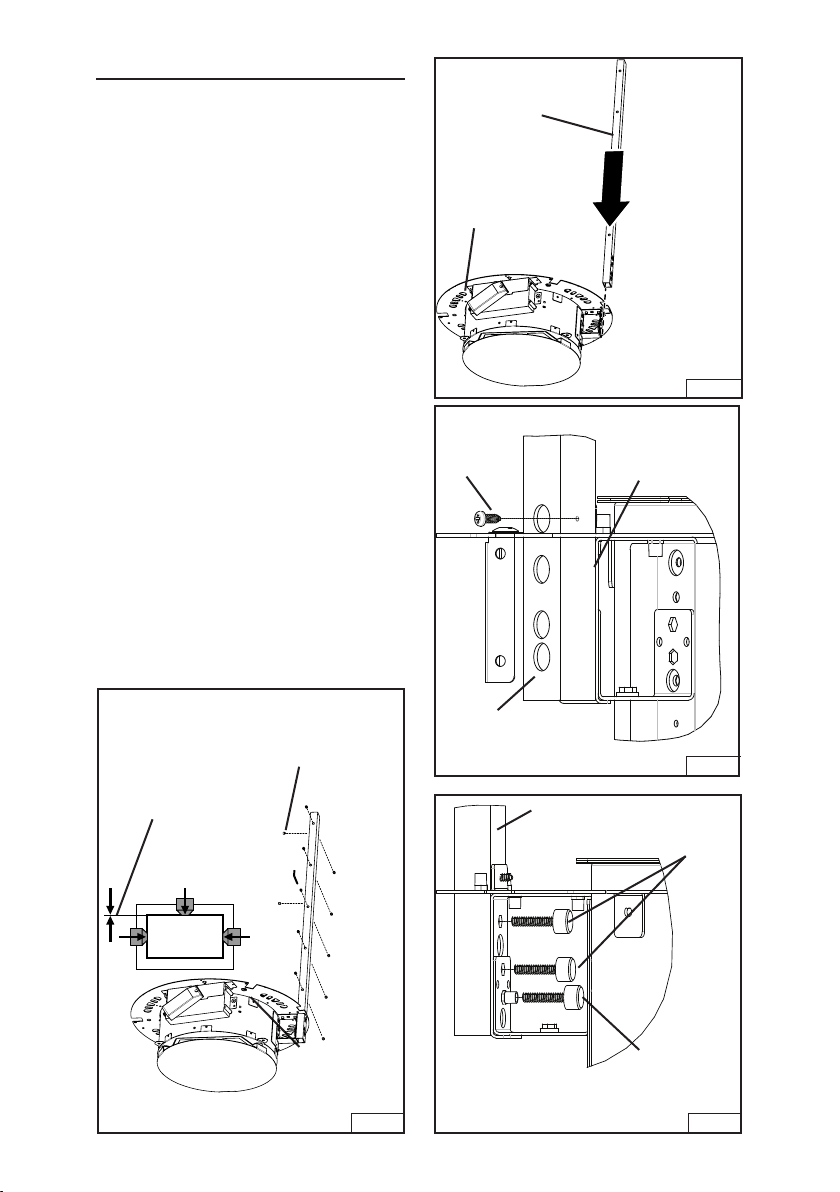
MOUNT POWER UNITS
1. Attach the lower support arms to each
power unit. Slide the support arm
through the slot in power unit flange.
Fig. 9.
2. Attach the arm to the power unit
flange with (1) M3 x 13mm sheet
metal screw. Fig. 10.
3. Continue to attach arm to power unit
with (2) M4x 24mm thumb screws.
Attach a third M4x 24mm thumb
screw to the threaded insert in the
power unit flange. This screw will be
used to level the power unit later .
Fig. 11.
4. Insert 12 set screws into each lower
support arm. Make sure the screws
do not protrude into the inner section
of the arm. Fig. 12.
Fig. 9
LOWER
SUPPORT
ARM
POWER
UNIT
FLANGE
Fig. 10
M3 x 13
SHEET
METAL
SCREW
SUPPORT
ARM
POWER
UNIT
FLANGE
Fig. 11
SUPPORT
ARM
LEVELING
THUMB
SCREW
THUMB
SCREW
Fig. 12
NOTE: SET
SCREWS
SHOULD NOT
PROTRUDE
SET
SCREWS
(12)
Loading ...
Loading ...
Loading ...