Operation & Installation Manual Continuous Flow Water Heater
Table of Contents
- Warnings & Important Information
- Regulatory Information
- Notice to Victorian Consumers
- Warning About Hot Water
- Operational Safety Information
- Features & Benefits
- Water Temperature Control
- Maximum Delivery Temperatures
- Operation Without Water Controllers
- Rinnai Water Controllers
- Location
- Water Resistance
- Temperature Control
- Water Controller Combinations & Configurations
- Wired Only Configurations
- Combined Wireless & Wired Configurations
- Universal Water Controller (MC-601Q) Operation
- Turning On
- Adjusting Temperature
- Transferring Priority
- Water Controller Combinations & Configurations
- Smartstart Pre-Heat System
- Preheat Function
- Preheat Aperation
- Water Controller Functions
- Trouble Shootin
- Error Codes
- No power display Wireless Water Controller (when fitted)
- Troubleshooting Without Water Controllers
- Service
- Installation Table of Contents
- Contacts
WATER CONTROLLER INSTALLATION
Master / Sub Water Controllers & Associated Temperatures
Only one MC model water controller can be designated as the 'Master' water controller. This water controller is normally used in the kitchen and usually has a maximum temperature of 55°C, which is sufficient for almost all kitchen applications. Temperatures higher than 55°C are possible but usually unnecessary and will result in higher gas use and increase the risk of burns.
Some additional conditions regarding Master Controller maximum temperatures apply when a wireless water controller is used as the 'Master' water controller.
- Temperatures of 55°C or higher can only be selected on the controller designated as the 'Master' water controller if the transceiver 'Max Temp' is also programmed to 55°C or higher.
- The temperature of hot water delivered is always limited to the maximum temperature programmed into the water heater itself. For example, if the transceiver maximum temperature is programmed to 55°C and the water heater is limited to 50°C, the maximum temperature that the water heater will deliver is 50°C. In this case 55°C will be displayed on the wireless Master Controller until a tap is opened after which the display will revert to 50°C.
The remaining water controllers are designated 'sub' controllers and are for use in bathrooms, toilets and laundries. The temperature limit for all 'Sub' controllers is always 50°C to minimise the risk of burns in these areas.
Adhesive labels are included for individual identification of wireless water controllers as master (Kitchen) or sub (Bathroom) water controllers. These labels are usually placed on the top back of the wireless water controller body
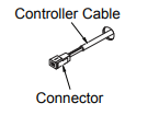
Communication Cables
Wired water controllers operate at an extra low voltage (12 Volts DC) which is supplied from the water heater, a 10 metre long communications cable is supplied for connection to the water heater. ONLY Rinnai supplied communication cables may be used. Optional longer communication cabling is available from Rinnai.
The water heater end of the cables are fitted with spade terminals. Only two pairs of cables (4 spade connectors in total) may be terminated. When attaching three or four cables it is necessary to join the cable terminals as follows:
For each pair cut off the existing spade connectors and re-terminate each pair into a new spade connector A (spade connectors are available from your local electrical component retailer) so that there are only two sets of spade connectors (4 spade connectors in total) to be terminated.
- Connecting One or Two Communication Cables - Single cables can be used when terminating up to two communication cables. Paired cables are to be used when terminating three or four communication cables. Follow steps 1 through 5 of "Communication Cable(s) & ’Ezi connect’" to terminate the cables to the water heater.
- Connecting Three or Four Communication Cables - To connect three or four cables, separate all the cables to be fitted into pairs.Follow steps 1 through 5 of "Communication Cable(s) & ’Ezi connect’" to terminate the joined cable pairs to the water heater.
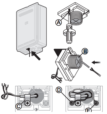
Communication Cable(s) & ’Ezi connect’
- Isolate the electric power supply by switching the power point off and removing the power plug of the water heater from the electric power socket.
- Remove the retaining screw A of the 'Ezi connect' cable connector at the base of the appliance.
- Swing the 'Ezi connect' cable connector door open and thread the cable through the weather seal of the cable access hole B in the direction shown allowing sufficient cable length so that the sheath of the cable can be secured with cable clamp C .
- Loosen screw terminals D & E and connect the cable spade connectors to these terminals and re-tighten. Polarity is not important, either wire colour can be connected to either terminal.
- Return the 'Ezi connect' cable connector to the original position taking care not to damage cable wires in the process and replace the retaining screw A .
UNIVERSAL WATER CONTROLLER (MC-601Q) INSTALLATION
- Determine the most suitable position
- Mark and drill 3 holes (mounting and cable access) refer to "Table 1. Appliance Dimensions" and "Diagram 1. Dimensions" on page 26 for water controller dimensions.
- When running cable through the access hole ensure the connector end of the cable is located nearest to the water controller.
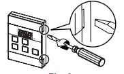
- Carefully remove the cover plates from the water controller, using a screwdriver.
- Connect the cable to the water controller. Feed any excess cable lengths into the wall cavity to avoid the pinching of cables between the wall and the water controller.
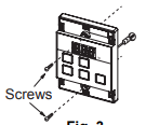
- Fix the water controller to the wall using the appropriate fixings.
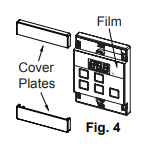
- Remove protective film from the water controller face and replace the cover plates.
TESTING
- Before final connection of the water heater purge gas, hot water and cold water supply lines. Debris or swarf in either the gas or water supplies may cause damage.
- Turn on gas and cold water supplies.
- Test for water leaks and gas escapes near the unit.
- Isolate gas supply. Remove test point screw located on the gas inlet connection and attach pressure gauge.
- Turn the power 'on' at the power point socket and turn on gas.
- If water controllers are fitted, ensure they are 'ON', with the maximum delivery temperature selected and open ALL available hot water outlets. If water controllers are not fitted, simply open ALL available hot water outlets.
- Operate ALL other gas appliances at their maximum gas rate, in accordance with manufacturers instructions.
- With all gas appliances in operation at maximum gas rate, the pressure should read between 1.13 - 3.0 kPa on Natural Gas. On LPG the pressure should be 2.75 - 3.0 kPa. If the pressure is lower, the gas supply is inadequate and the appliance will not operate to specification. It is the Installers responsibility to check the gas meter, service regulator and pipe work for correct operation/sizing and rectify as required.
- Close hot water taps including the shower.
- Inspect and clean the strainer located on the cold water inlet connection. This procedure may need to be repeated to ensure the strainer remains clear, especially on new installations.
- If water controllers are fitted, it is necessary to test their operation through the complete range of functions (refer to the Operation sections of this manual).
- Confirm the hot water delivery temperature(s) using a thermometer. If controllers are fitted, ensure temperatures exceeding 50°C cannot be selected on bathroom or ensuite controllers. Refer to the section ‘Delivery Temperature’ below for more details.
- After testing is completed, explain to the householder the functions and operation of the water heater and water controllers (if fitted). Ensure the "Installation Record" on page 25 is filled in and that this booklet is handed to the customer. Reminding the customer to complete the Warranty Card and forward to Rinnai
GAS PRESSURE SETTING
The regulator is electronically controlled and factory pre-set. Under normal circumstances it DOES NOT require adjustment during installation. Make adjustments ONLY if the unit is not operating correctly and all other possible causes for incorrect operation have been eliminated. Instructions for gas pressure setting are located in the instruction pocket inside the appliance front cover.