This Appliance complies
with cusrrent AS 3498
SAI GLOBAL LIC. WMKA00169
This appliance must be installed in accordance with:
• Manufacturer’s Installation Instructions
• Current AS/NZS 3000 Wiring Rules
• Municipal Building Codes
• Current AS/NZS 3500.4 Plumbing and Drainage - Heated Water Services
• All local regulatory requirements, including all local OH&S requirements
This appliance must be installed, maintained and removed by a Qualified Person.
For continued safety of this appliance it must be installed and maintained in
accordance with the manufacturers instructions.
Installation Manual
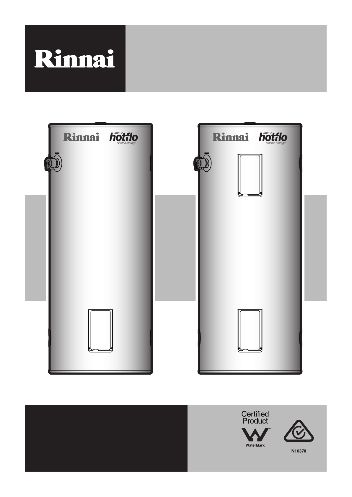
HOTFLO (EHFA/EHFD) Series
Mains Pressure Vitreous Enamel
Electric Storage Water Heater

Rinnai 2 EHFA/EHFD HW IM
This page is intentionally blank

Rinnai 3 EHFA/EHFD HW IM
TABLE OF CONTENTS
Warnings & Safety 5
Regulatory ����������������������������������������������������������������������������������������������������������������������������������������������������������������������������� 5
Notice To Victorian Consumers ��������������������������������������������������������������������������������������������������������������������������������������������� 5
Safety ������������������������������������������������������������������������������������������������������������������������������������������������������������������������������������� 6
Hydrogen Gas ������������������������������������������������������������������������������������������������������������������������������������������������������������������������ 6
Water Temperature ���������������������������������������������������������������������������������������������������������������������������������������������������������������� 6
Scald Hazards ����������������������������������������������������������������������������������������������������������������������������������������������������������������������� 6
Safety Devices ����������������������������������������������������������������������������������������������������������������������������������������������������������������������� 7
Pressure & Temperature Relief (PTR) Valve ������������������������������������������������������������������������������������������������������������������������� 7
Expansion Control Valve (ECV) ��������������������������������������������������������������������������������������������������������������������������������������������� 7
Important Information 8
Anode ������������������������������������������������������������������������������������������������������������������������������������������������������������������������������������ 8
Water Quality ������������������������������������������������������������������������������������������������������������������������������������������������������������������������� 8
Operational Overview ������������������������������������������������������������������������������������������������������������������������������������������������������������ 8
Turning Water Heating System ‘OFF’ ������������������������������������������������������������������������������������������������������������������������������������ 8
Turning Water Heating System ‘ON’ �������������������������������������������������������������������������������������������������������������������������������������� 8
Draining �������������������������������������������������������������������������������������������������������������������������������������������������������������������������������� 8
Care & Maintenance 9
Save A Service Call ��������������������������������������������������������������������������������������������������������������������������������������������������������������� 9
Periodic Maintenance & Servicing ����������������������������������������������������������������������������������������������������������������������������������������� 9
Specications 10
Appliance Components �������������������������������������������������������������������������������������������������������������������������������������������������������� 10
Table 1� Dimensions & Weight ����������������������������������������������������������������������������������������������������������������������������������������������11
Table 2. Ratings & Other Specications �������������������������������������������������������������������������������������������������������������������������������11
InstallationMethods 12
Hot Water Plumbing System Example - No TLD ����������������������������������������������������������������������������������������������������������������� 12
Hot Water Plumbing System Example - With TLD ��������������������������������������������������������������������������������������������������������������� 12
Hot Water Plumbing system Example / Flow & Return Pipe Work - No TLD ���������������������������������������������������������������������� 13
Hot Water Plumbing System Example / Flow & Return Pipe Work - With TLD ������������������������������������������������������������������� 13
Installation 14
Location ������������������������������������������������������������������������������������������������������������������������������������������������������������������������������� 14
Water Quality ����������������������������������������������������������������������������������������������������������������������������������������������������������������������� 14
Mains Pressure �������������������������������������������������������������������������������������������������������������������������������������������������������������������� 14
THERMOSTAT SETTING ���������������������������������������������������������������������������������������������������������������������������������������������������� 15
Reducing The Risk Of Scalding ������������������������������������������������������������������������������������������������������������������������������������������� 15
Plumbing Connections ��������������������������������������������������������������������������������������������������������������������������������������������������������� 15
Connections to the water heater ������������������������������������������������������������������������������������������������������������������������������������������ 15
Water Pipes ������������������������������������������������������������������������������������������������������������������������������������������������������������������������� 15
Pressure and Temperature Relief (PTR) Valve �������������������������������������������������������������������������������������������������������������������� 16
Expansion Control Valve (ECV) ������������������������������������������������������������������������������������������������������������������������������������������� 16
Pressure Limiting Valve (PLV) ��������������������������������������������������������������������������������������������������������������������������������������������� 16
Relief Valve Drain Lines ������������������������������������������������������������������������������������������������������������������������������������������������������� 16
Electrical Supply ������������������������������������������������������������������������������������������������������������������������������������������������������������������ 17
Electrical Connections ��������������������������������������������������������������������������������������������������������������������������������������������������������� 17
Wiring Diagrams ������������������������������������������������������������������������������������������������������������������������������������������������������������������ 18
Thermostat Setting ������������������������������������������������������������������������������������������������������������������������������������������������������������� 18
Commissioning 19
To ll & turn ‘ON’ the water heater �������������������������������������������������������������������������������������������������������������������������������������� 19
To turn ‘OFF’ the water heater �������������������������������������������������������������������������������������������������������������������������������������������� 19
Contacts 20

Rinnai 4 EHFA/EHFD HW IM
This page is intentionally blank

Rinnai 5 EHFA/EHFD HW IM
READ ALL INSTRUCTIONS BEFORE USING THE APPLIANCE.
Always comply with the following precautions to avoid dangerous situations and to ensure
optimum performance.
Failure to carefully read and follow all instructions in this manual can result in equipment
malfunction, property damage, personal injury and/or death.
YourRinnaiHotoMainsPressureVitreousEnamelElectricStorageWaterHeaterhasbeen
certied by relevant plumbing and electrical authorities and the details are shown on data
plate.
WARNINGS:WHENIGNORED,CANRESULTINSERIOUSINJURYORDEATH.
CAUTIONS:WHENIGNORED,CANRESULTINMINORINJURYORPRODUCTDAMAGE.
REGULATORY
WARNING
This appliance shall be installed in accordance with these instructions and all regulatory
requirements which exist in your area including those in relation to manual lifting, working at
heightsandonroofs.Applicablepublicationsandregulationsmayinclude:
•
AS/NZS3500NationalPlumbingandDrainage
•
AS/NZS3000Wiringrules
•
Building Codes of Australia (BCA)
•
LocalOccupationalHealthandSafety(OH&S)regulations
•
LocalRegulationsandMunicipalBuildingCodes
DO NOToperatethissystembeforereadingthemanufacturersinstructions.
This appliance must be installed, commissioned and serviced by an authorised person in
accordancewithallapplicablelocalrulesandregulations.
Forcontinuedsafetyofthisapplianceitmustbeinstalled,operatedandmaintainedinaccordance
with the manufacturer’s instructions.
Thisapplianceisheavy,use2peopleormechanicalliftingdevice.Improperliftingmayresultin
serious injury.
Takecarewhenopeningorunpackingthisappliance.Failuretodosomayresultinseriousinjury
or product failure.
DO NOT modify the electrical wiring of this appliance. If the control power wiring is damaged
ordeterioratedthenitmustbereplacedbyanauthorizedperson.Failuretodosomayresultin
electricshock,re,seriousinjuryorproductfailure.
Removaloftheaccesscoversofwaterheatingsystemwillexpose240VwiringandMUSTOnly
beremovedbyanauthorisedperson.
CareshouldbetakennottotouchthepipeworkasitmaybeHOT!
DO NOT place articles on or against this appliance.
DO NOTstorechemicalsorammablematerialsnearthisappliance.
DO NOT operate with collectors or covers removed from this appliance.
DO NOT activate pump unless cylinder is full of water.
Thisapplianceisnotsuitableforuseasadomesticspapoolorswimmingpoolheater.
NOTICE TO VICTORIAN CONSUMERS
WARNING
ThisapplianceMUST BEinstalledbyapersonlicensedwiththeVictorianBuildingAuthority.
ONLY a licensed person will have insurance protecting their workmanship.
So make sure you use a licensed person to install this appliance and ask for your Compliance
Certicate.
ForfurtherinformationcontacttheVictorianBuildingAuthorityon1300815127
IMPORTANT
WARNINGS & SAFETY
Rinnai 6 EHFA/EHFD HW IM
SAFETY
WARNING
ThisapplianceisNOTintendedforusebypersons(includingchildren)withreducedphysical,
sensoryormentalcapabilities,orlackofexperienceandknowledgeunlesstheyhavebeengiven
supervision or instruction concerning use of the appliance by a person responsible for their
safety.
ChildrenshouldbesupervisedtoensurethattheyDONOT play with the appliance.
Hydrogen Gas
If the hot water heater is not used for two weeks or more, a quantity of hydrogen gas, which is highly ammable,
may accumulate in the water heater� To dissipate this safety, it is recommended that a non electrically operated
hot tap be turned on for several minutes at a sink, or bath, but not a dishwasher or other appliance� During this
procedure there must be no smoking, open ame or any electrical appliance operating nearby. If hydrogen gas is
discharged through the tap, it will probably make a sound like air escaping�
Water Temperature
To meet regulatory requirements the temperature of stored water MUST NOT be less than 60°C� The thermostat
on your water heater is factory pre-set to 70°C� The thermostat setting can be adjusted between 60°C and 70°C
by an electrician or other suitably qualied trades person.
WARNING
ThethermostatsettingmustonlybeadjustedbyanElectricianorothersuitablyqualiedtrades
person.
TheaccesscovertotheelementandthermostatmustonlyberemovedbyanElectricianorother
suitablyqualiedtradesperson.
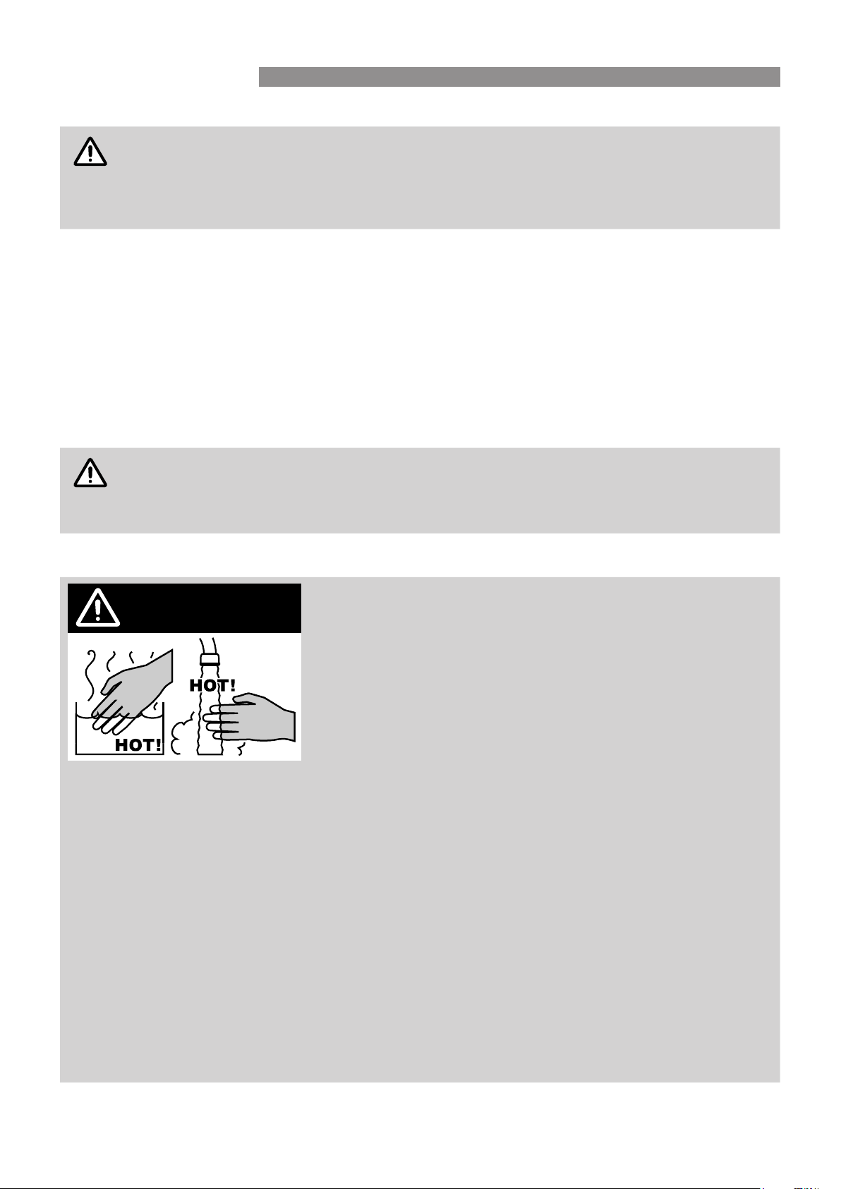
SCALD HAZARDS
Hot Water can cause scalds.
Children, disabled, and the elderly are at the highest risk of
being scalded.
Feel water temperature before bathing or showering.
Scalds from hot water taps can result in severe injuries to
young children.
Scalds can occur when children are exposed directly to hot
water when they are placed into a bath which is too hot.
Always......
Testthetemperatureofthewaterwithyourelbowbeforeplacingyourchildinthebath,alsocarefullyfeel
waterbeforebathingorshoweringyourself.
Supervisechildrenwhenevertheyareinthebathroom.
Make sure that the hot water tap is turned off tightly.
Consider.....
Installingchildprooftapcoversorchildresistanttaps(bothapproacheswillpreventasmallhandbeing
abletoturnonthetap).
Installing tempering valves or thermostatic mixing valves which reduce the hot water temperature delivered
tothetaps.Yourlocalplumbingauthoritymayalreadyrequirethatthesebetted.Contactyourinstaller
orlocalplumbingauthorityifindoubt.
Never….
Leave a toddler in the care of another child. They may not understand the need to have the water
temperature set at a safe level.
DANGER BEWARE OF
SCALDING HAZARDS
WARNINGS & SAFETY
Rinnai 7 EHFA/EHFD HW IM
SAFETY DEVICES
For safe operation this water heater is tted with a combination Pressure & Temperature Relief Valve, a thermostat
and an over-temperature cut out for each heating element�
WARNING
DO NOT tamper with or remove safety devices.
DO NOToperatethiswaterheaterunlessallsafetydevicesarettedandinworkingorder.
Theoperationofthethermalcutoutindicatesapossiblydangeroussituation.DO NOT reset the
thermalcutoutuntilthewaterheaterhasbeenservicedbyaqualiedperson.
Pressure & Temperature Relief (PTR) Valve
This valve is located near the top of the water heater and is essential for safe operation�
WARNING
DO NOT sealorblocktheoutletofthePTRvalveoritsdrainpipe.
DO NOT replacethePTRvalvewithonethathasahigherpressureratingthanisspeciedfor
the water heater.
The PTR valve should be checked for performance or replaced at intervals not exceeding 5 years, or more frequently
in areas with a high incidence of water deposits by a qualied person. The easing gear must be operated at least
once every six months or more frequently in areas with a high incidence of water deposits�
WARNING
Failure to do this may result in the water heater cylinder failing or under certain circumstances,
exploding.Waterdischargedwillbeveryhot.Exercisecaretoavoidscaldinjury.Ifthevalvedoes
notsealagainwhentheeasinggearisclosed,contactRinnaitoarrangeinspectionbyaqualied
person.
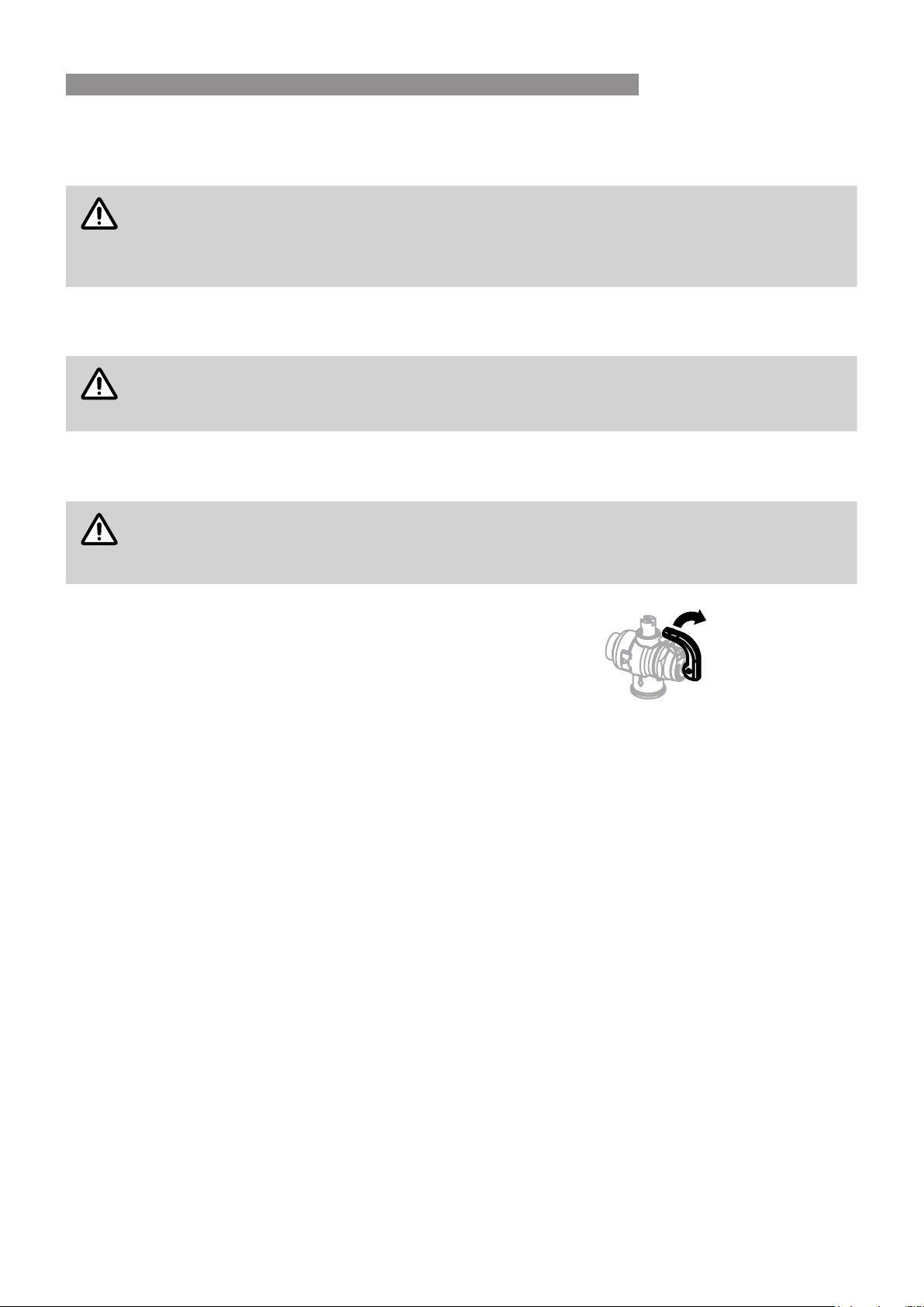
It is important you raise and lower the easing gear gently� If the valve does not
discharge water when the easing gear lever is lifted, there may be a serious
problem and the power supply in the meter box (the switch marked ‘Water
heater’ or ‘hot water’) or the isolating switch installed near the water heater
must be switched off immediately� Contact Rinnai to arrange inspection by
a qualied person.
It is normal for the PTR valve to release a small quantity of water through the drain pipe during heating� If the valve
dribbles or leaks continuously, try easing the valve gear for a few seconds� This may dislodge any foreign matter
and stop leakage� If leakage does not stop there may be a problem as detailed below:
•
If there are heavy ows of water until the water heater is cold which then stops until the water reheats there may
be a serious problem and the power supply in the meter box (the switch marked ‘Water heater’ or ‘hot water’) or
the isolating switch installed near the water heater must be switched off immediately� Contact Rinnai to arrange
inspection by a qualied person.
•
If there is a steady ow for long periods, often at night, it may be as a result of the water pressure exceeding the
design pressure of the water heater� Contact your installing plumber as a Pressure Limiting Valve (PLV) may
be required�
Expansion Control Valve (ECV)
An ECV is recommended in all geographical areas where the water supply has a tendency to cause scaling,
including South Australia and Western Australia. Local regulatory authorities may require that an ECV be tted.
The ECV is to be supplied and tted by the installer. Refer to the section Water Quality for more information on
scaling water�
If an ECV is tted, operate the easing gear at least once every six months to remove any deposits and to verify
that it is not blocked�
The ECV should be checked for performance or replaced at intervals not exceeding 5 years, or more frequently in
areas with a high incidence of water deposits by a qualied person.
It is normal and desirable that the ECV allows a small quantity of water to be discharged through the drain pipe
during the heating cycle� If the valve dribbles or leaks continuously, operate the easing gear for a few seconds� This
may dislodge any foreign matter and stop leakage� If leakage does not stop Contact Rinnai to arrange inspection
by a qualied person.
Gently lift lever
until water flows
from drain line,
lower lever gently
to close
WARNINGS & SAFETY

Rinnai 8 EHFA/EHFD HW IM
ANODE
The water heater is tted with a sacricial anode to extend it’s life. It will slowly dissipate whilst protecting the
cylinder� The life of the water heater may be extended by arranging for an authorised person to inspect the anode
and replace it if required. It is recommended that the anode be inspected at least every 5 years. The factory tted
Rinnai anode is Magnesium based� This anode is suitable when the total dissolved solids (TDS) content in the
water supply does not exceed 600 mg/L, which is the case in most areas� In areas where the total dissolved solids
(TDS) content in the water supply exceeds 600 mg/L the Rinnai aluminium based anode is required�
WATER QUALITY
The water quality of most public supplies is suitable for the water heating system� The water quality from bore
wells is generally unsuitable for the water heating system� Refer to the ‘Warranty Conditions’ for water quality
parameters and how they affect the warranty conditions� If in doubt about the water quality, have it checked against
the parameters listed in the warranty conditions� If sludge or foreign matter is present in the water supply, a suitable
strainer lter should be incorporated in the water supply to the system.
OPERATIONAL OVERVIEW
(How the hot water system works)
Single Element Model: A vitreous enamel lined steel cylinder stores water which is heated by a single
thermostatically controlled heating element, located at the base of the cylinder� The water heater connects directly
to the mains water supply� The heating element can be connected to a Continuous or Off-Peak electricity supply�
The continuous supply is appropriate when the water heater capacity is less than the daily usage of hot water� The
Off-Peak supply is appropriate when the water heater capacity exceeds the daily usage of hot water� The Off-Peak
supply allows heating only for set periods and a volume of water sufcient for daily usage is heated during the set
period and stored� The Off-Peak supply is usually cheaper� Electricity supply types and tariffs vary according to the
local electricity authority�
Twin Element Model: A vitreous enamel lined steel cylinder stores water which is heated by a twin thermostatically
controlled heating elements, one element is located at the base of the cylinder, while the other is located near the
top� The water heater connects directly to the mains water supply� The bottom heating element heats the whole
contents of cylinder and Top heating element (booster) only operates during the high demand periods to heat the
upper portion of the contents of the cylinder� The two heating elements are wired for non-simultaneous operation,
so that only one heating element can operate at a time� The bottom heating element can be connected to an
Off-Peak electricity supply, and the top heating element to a continuous electricity supply�
Turning Water Heating System ‘OFF’
If the water heater is not going to be used for only a few days, we suggest you leave it switched on� If it is necessary
to switch off the water heater, the switch is usually marked and located in the electricity meter box of the building�
Turning Water Heating System ‘ON’
Switch on the electric supply to the heating elements� The switch is usually marked and located in the electricity
meter box of the building� Water heating will now occur as required� It may take a number of hours before hot water
is available�
DRAINING
WARNING
DrainingMUST BE carriedoutbyaqualiedperson.
WatermaybeHOT during draining.
Drain the water heater as follows:
1� Isolate or turn ‘OFF’ the water heater at the electricity supply�
2� Close the cold water isolation valve at the inlet to the water heater�
3� Close all hot water taps�
4� Operate the PTR valve easing gear - gently� Operating the PTR valve easing gear will relieve the pressure
in the water heater�
5� Undo the cold water inlet union� Attach a hose to the water heater side of the union� Let the other end of the
hose go to a drain�
6� Operate the PTR valve easing gear again� This allows air into the water heater and will result in water draining
through the hose�
IMPORTANT INFORMATION
Rinnai 9 EHFA/EHFD HW IM
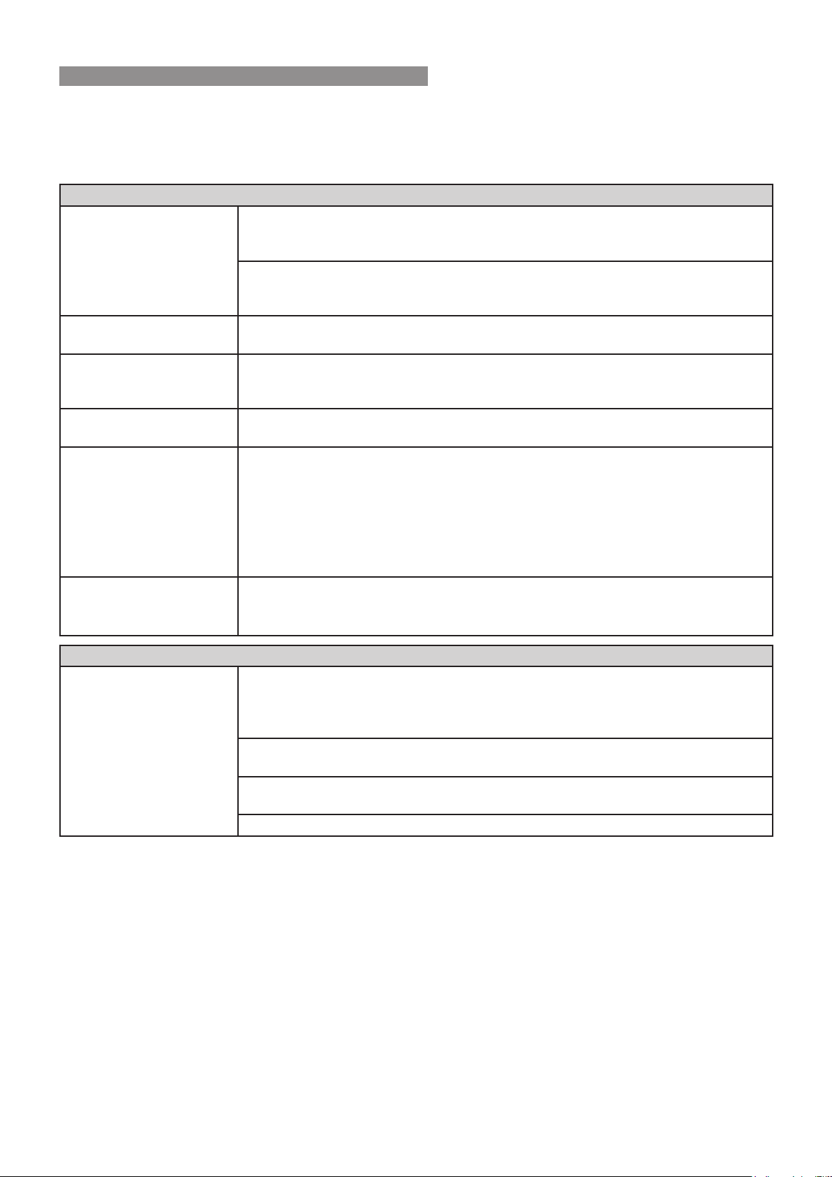
SAVE A SERVICE CALL
Check the items below before requesting a service� Service and parts charges may be incurred where it is found
that there is no fault with the water heater and the issue is related to the plumbing installation or is due to the failure
of water or electric supplies�
Insufcientornohotwater
Is the electricity supply
connected?
Check that the isolating switch marked “HOT WATER” or “WATER HEATER” at the
meter box is switched on� Check also that any isolating switches installed near the
water heater are switched on�
Check the fuse or circuit breaker marked “HOT WATER” or “WATER HEATER” at
the meter box� Repeated failure of fuse or tripping of circuit breaker indicates a fault
which must be investigated by an authorised trades person�
Is your unit a Twin Element
electric water heater?
A twin element model (non-simultaneous) must have a continuous electricity supply
to the top heating element� Check that this is the case�
Are you using more hot
water than you think?
Often it is not realized how much hot water is actually used� This applies especially
to showering� Review hot water usage, especially the time taken for showering, and
investigate the use of ow control valves or Water saving shower roses.
Are water heater valves
discharging excessively?
Refer to the section “Safety Devices” on page 7�
Thermostat settings? Check the temperature of hot water delivered with a thermometer placed under the
closest outlet (usually the kitchen sink) on a non-tempered hot water line�
This test should be done early in the morning after overnight electrical boosting
before any hot water is used� The temperature of the water delivered should be at
least 55°C (allowing for heat losses in pipe work)�
If this is not the case, the temperature may need to be increased� Contact your
installer or Rinnai to discuss adjusting the thermostat�
No water from the hot tap? Restriction in the hot tap or failure of the cold water supply to the heater�
Check for water ow at the other hot taps and that the cold water isolation valve is
fully open�
HighElectricityBills
If you think your electricity
bill is too high, check for
these possibilities�
If, after investigating, and
you still require assistance
contact Rinnai.
You may be using more hot water than you think� This applies especially to showering�
Review hot water usage, especially the time taken for showering, and investigate the
use of ow control valves or ‘water saving’ shower roses. Investigate recent changes
to hot water usage patterns�
Water heater valves may be discharging excessively� Refer to the section “Safety
Devices” on page 7�
There may be hot water leakages in hot water pipes or taps� Have these checked and
rectied by a plumber.
There may have been changes in electricity tariffs since your last bill�
PERIODIC MAINTENANCE & SERVICING
If overow tray and drain are tted, it is the users responsibility to have these checked periodically to ensure there
are no blockages�
The user should operate the easing gear of the ECV and PTR valve (if tted) every 6 months as described under
“Safety Devices” on page 7�
Rinnai service network personnel are fully trained and equipped� If your Rinnai appliance requires servicing contact
Rinnai as per the details on the back page of this manual� Rinnai recommends that this commercial appliance be
inspected and serviced by a qualied person every 12 months.
The ECV and PTR valve MUSTBE checked for performance or replaced by a qualied person at intervals not
exceeding 5 years or more frequently in areas where the water is classied as scaling water. Refer to both the
“Anode” and “Water Quality” on page 8 for Anode selection, inspection and maintenance requirements)�
If the electric supply conduit to the water heater is damaged, it MUSTBE replaced by a qualied person in order
to avoid a hazard�
CARE & MAINTENANCE

Rinnai 10 EHFA/EHFD HW IM
APPLIANCE COMPONENTS
1� Data / Warning labels
2� Left hand cold water inlet
Connection RP 3/4" (20mm)
3� Element / thermostat / electrical supply connection cover
*
4� PTR valve drain pipe
Copper only drain in accordance with AS/NZS 3500.4
5� Element / thermostat cover (Twin element models only)
*
6� Left hand hot water outlet
Connection RP 3/4" (20mm), use a union connection and insulate hot water pipe
7� PTR valve connection
RP 1/2" (15mm), use supplied PTR Valve
8� Anode cap
9� Right hand (duplicate) hot water outlet
Connection RP 3/4" (20mm), use a union connection and insulate hot water pipe
10� Right hand (duplicate) cold water inlet
11� Water heater support
In accordance with AS/NZS 3500.4
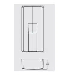
12� Safe Tray & drain
Where required, in accordance with AS/NZS 3500.4
NOTE
*
RemovalandconnectionbyqualiedpersonsONLY,inaccordancewithAS/NZS3000
ValveswithpressureratingsotherthanspeciedareunsuitableandMUST NOTbeused.
WATER HEATER - located closest to most frequently used outlet - Access for service in the
installed position.
11
5
6
9
1032
7
8
1a
12
4
1b
SPECIFICATIONS
Rinnai 11 EHFA/EHFD HW IM
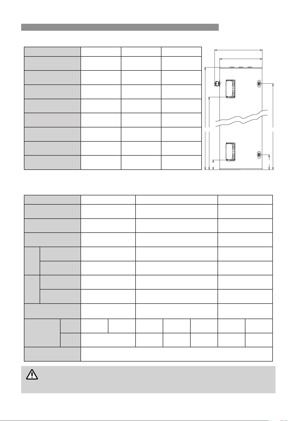
TABLE 1. DIMENSIONS & WEIGHT
Models EHFD 160 EFHA 250 EHFA 315
A 1313 1484 1770
B 600 674 674
C 537 605 605
D 1107 1248 1541
E 186 210 210
F 110 135 135
G n/a 985 1225
Weight (kg) 51 71 91
All dimensions are in mm unless otherwise stated
TABLE 2. RATINGS & OTHER SPECIFICATIONS
Models EHFD 160 EFHA 250 EHFA 315
Cylinder Rated Pressure
(kPa)
1000 1000 1000
PTR Rated Pressure
(kPa)
1000 1000 1000
ECV Rated Pressure
(kPa)
850 850 850
ECV
Fitted
(kPa)
Fit PLV if mains
pressure exceeds
680 680 680
Recommended
PLV pressure rating
500 500 500
ECV
Not
Fitted
(kPa)
Fit PLV if mains
pressure exceeds
800 800 800
Recommended
PLV pressure rating
500 500 500
Rated Capacity Hot Water
Litres (l)
160 250 315
Heating Element
(W)
Lower 2400 3600 2400 3600 4800 3600 4800
Upper n/a n/a 3600 4800 3600 4800
Inlet/Outlet Connections 3/4" (20 mm)
NOTE
APLVisnotsuppliedwiththesemodels.APLVMUST BEttediftheMainsPressureexceeds
thelimitsshown.IfthemainspressureiswithinthelimitsshowntmentofthePLVisoptional.
However,itisrecommendedthatthePLVisttedinallinstallationsasitaidswaterandenergy
conservation.
A
F
G
C
B
E
D
OUTLETSP&TR
INLETS
SPECIFICATIONS

Rinnai 12 EHFA/EHFD HW IM
HOT WATER PLUMBING SYSTEM EXAMPLE - NO TLD
*PTR VALVE
(Supplied)
KITCHEN
LAUNDRY
NON TEMPERED SUPPLY
BATHROOM
ENSUITE
TO DRAIN
COLD
SUPPLY
Isolating
Valve
*ECV
TO DRAIN
Non-return
Valve
*PLV
WATER
HEATER
(Not Supplied)
CAUTION
ValveswithpressureratingsotherthanspeciedareunsuitableandMUST NOT beused.
*
Forratingssee"Table2.Ratings&OtherSpecications"onpage11.
HOT WATER PLUMBING SYSTEM EXAMPLE - WITH TLD
KITCHEN
LAUNDRY
ENSUITE
BATHROOM
TEMPERED
SUPPLY Temperature
Limiting Device
(TLD)
COLD
SUPPLY
Non-return
Valve
*PLV
Isolating
Valve
Isolating
Valve
*PLV
*ECV
(OR)
WATER
HEATER
Non-return Valve
COLD
SUPPLY
Non-return
Valve
Non-return
Valve
WATER
HEATER
Temperature
Limiting Device
(TLD)
Non-return
Valve
*PTR VALVE
(Supplied)
TO DRAIN
*ECV
TO DRAIN
TO DRAIN
(Not Supplied)
TEMPERED
SUPPLY
*PLV
NON TEMPERED SUPPLY
NON TEMPERED SUPPLY
Isolating
Valve
Non-return
Valve
CAUTION
ValveswithpressureratingsotherthanspeciedareunsuitableandMUST NOT beused.
*
Forratingssee"Table2.Ratings&OtherSpecications"onpage11.
It may be a requirement that the hot and cold water supply pressures to a Temperature Limiting Device (TLD) are
equal� If this is the case, a PLV with the same pressure rating as the PLV for the hot water is required for the TLD
as shown�
INSTALLATION METHODS
Rinnai 13 EHFA/EHFD HW IM
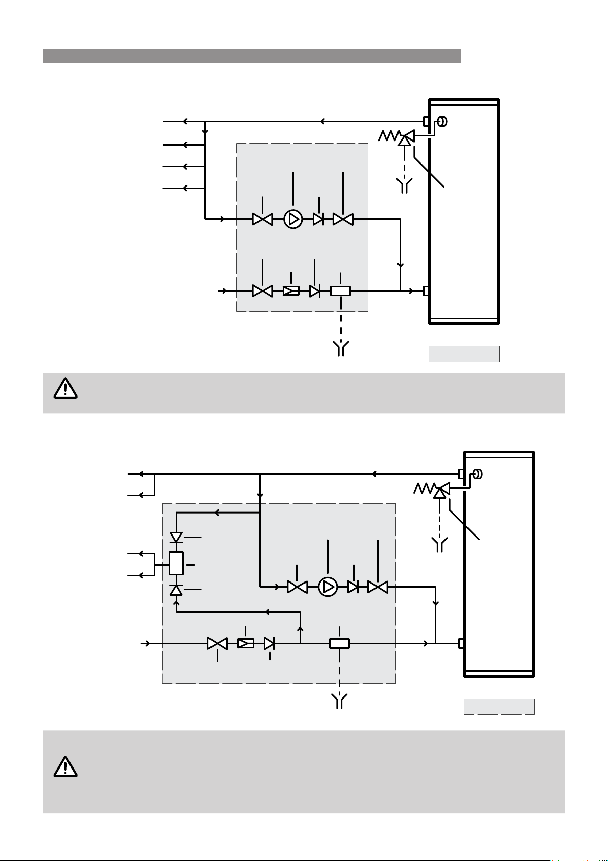
HOT WATER PLUMBING SYSTEM EXAMPLE / FLOW & RETURN PIPE WORK - NO TLD
COLD
SUPPLY
Isolating
Valve
*ECV
TO DRAIN
Non-return
Valve
*PLV
KITCHEN
LAUNDRY
NON TEMPERED SUPPLY
BATHROOM
ENSUITE
*PTR VALVE
(Supplied)
TO DRAIN
WATER
HEATER
(Not Supplied)
Non-return
Valve
Isolating
Valve
Isolating
Valve
Flow & Return
Pump
CAUTION
ValveswithpressureratingsotherthanspeciedareunsuitableandMUST NOT beused.
*
Forratingssee"Table2.Ratings&OtherSpecications"onpage11.
HOT WATER PLUMBING SYSTEM EXAMPLE / FLOW & RETURN PIPE WORK - WITH TLD
COLD
SUPPLY
Isolating
Valve
*ECV
TO DRAIN
Non-return
Valve
*PLV
KITCHEN
LAUNDRY
NON TEMPERED SUPPLY
BATHROOM
ENSUITE
TO DRAIN
*PTR VALVE
(Supplied)
WATER
HEATER
(Not Supplied)
Non-return
Valve
Non-return
Valve
Non-return
Valve
Isolating
Valve
Isolating
Valve
Flow & Return
Pump
Temperature
Limiting Device
(TLD)
CAUTION
ValveswithpressureratingsotherthanspeciedareunsuitableandMUST NOT beused.
*
Forratingssee"Table2.Ratings&OtherSpecications"onpage11.
1. Thisschematicisanexampleonly,variationsmayalsobesuitable.
2. TemperedwaterfromaTLDCANNOTbere-circulated.TheTLDMUST BE positioned in
adeadleg,branchingoffthecirculatedhotwaterowandreturnpipe.
INSTALLATION

Rinnai 14 EHFA/EHFD HW IM
This appliance MUSTBE installed by a qualied person in accordance with:
•
Manufacturers installation instructions
•
Current AS/NZS 3000 Wiring Rules
•
Current AS/NZS 3500�4 Plumbing and Drainage - Heated Water Services
•
All local regulatory requirements
This appliance is NOTsuitable for use as a spa or swimming pool heater�
LOCATION
The Rinnai Hoto (EHFA/EHFD) storage water heater range have an ingress protection rating of IPX4 making
them suitable for internal or external installation�
The water heater should be placed as close as practicable to the most frequently used hot water outlet point or
points to minimize the delay time for hot water delivery� This will usually be the kitchen tap� For installations where
the distance between the water heater and the outlets is considerable, a ow and return system can be used which
will minimize the waiting time for hot water delivery�
It is recommended that the water heater is installed at ground or oor level. It MUSTBE installed in a vertically
upright position� The water heater MUSTBE accessible without the use of a ladder or scaffold� Installation into roof
spaces MUST comply with local regulatory authority requirements�
Ensure the PTR valve, isolating valves, access covers, thermostats and heating elements have sufcient clearances
and are accessible for service and removal� The information on the rating plates MUST also be readable�
The water heater MUST BE installed in free standing mode on a level and stable base in a manner that is
acceptable to local authorities� Avoid situations that may result in pooling of water around the base of the water
heater�
Where property damage can occur as a result of water leakage, the water heater MUSTBE installed with a safe
tray (overow tray) and drain. Construction, installation and draining of the safe tray MUST comply with local
regulatory requirements and� AS/NZS 3500�4 also requires the use of a safe tray for particular situations�
WATER QUALITY
The water quality of most public supplies is suitable for the water heater� Water quality from bore wells is generally
unsuitable� Refer to the ‘Warranty Conditions’ for water quality parameters and how they affect warranty� If in doubt
about water quality, have it checked against the parameters listed in the warranty conditions�
If sludge or foreign matter is present in the water supply, a suitable strainer or lter should be incorporated in the
water supply to the water heater�
Scaling water is dened as having a total hardness in excess of 200 mg/litre (expressed as calcium carbonate) or
a Saturation Index in excess of +0�4� Areas that have a scaling water supply include South Australia and Western
Australia� In a scaling water supply, calcium carbonate and possibly other compounds are deposited out of the
water onto any hot metallic surfaces and form a scale�
In areas of scaling water an ECV MUSTBE tted on the cold water line between the non‑return valve and the
connection to the water heater to protect the PTR valve and the water heater� Local regulatory authorities may
require that an ECV be tted. The ECV is to be supplied and tted by the installer.
MAINS PRESSURE
The Hoto (EHFA/EHFD) electric storage water heater range utilise mains pressure by connecting directly to the
mains water supply� If the mains water supply pressure in your area exceeds the rated pressure of the water heater
a PLV MUSTBE tted.
The mains water supply pressure should be greater than 350kPa for true mains pressure operational performance
to be achieved�
INSTALLATION

Rinnai 15 EHFA/EHFD HW IM
THERMOSTAT SETTING
The thermostat setting can be adjusted between 60°C and 70°C� It has been factory pre-set to 70°C�
WARNING
ThethermostatsettingsMUST ONLYbeadjustedbyaqualiedperson.
REDUCING THE RISK OF SCALDING
This water heater can deliver water at temperatures which can cause scalding� Children, disabled and the elderly
are at the highest risk or being scalded�
Local regulatory requirements and the requirements of AS/NZS 3500�4 MUSTBE considered regarding temperature
limitations of hot water delivered to areas used primarily for personal hygiene such as bathrooms and ensuites�
The delivery temperature may be limited to 45°C for early childhood centres, primary and secondary schools
and nursing homes or similar facilities for the young, aged, sick or people with disabilities and 50°C for all other
buildings� These temperatures will reduce the risk of scald injury and can be achieved by the use of a TLD, for
example a thermostatic mixing valve or tempering valve�
Rinnai recommend that an approved TLD is tted into the hot water pipe work from the water heater to areas used
primarily for personal hygiene such as bathrooms and ensuites to reduce the risk of scalding�
Refer to the installation congurations "Hot Water Plumbing System Example ‑ With TLD" on page 12 and "Hot
Water Plumbing System Example / Flow & Return Pipe Work ‑ With TLD" on page 13.
PLUMBING CONNECTIONS
Connections to the water heater
Refer to Specications for the plumbing connection sizes and location (Table 1) and the specied pressure ratings
of valves (Table 2). Refer also to the diagrams under “Installation Congurations”.
WARNING
ValveswithpressureratingsotherthanspeciedMUST NOTbeused.
An isolation valve and non-return valve MUSTBE tted in the cold water supply to the water heater so the water
heater can be isolated� Combination isolation and non-return valve such as 'Duo' or 'Trio' valves are suitable for
this purpose�
Isolation valves MUSTNOT be tted directly to the appliance. Use disconnection unions between the water heater
and the valves to allow the water heater to be disconnected from pipework at a later date�
Purge pipework to remove swarf and other foreign matter before nal connection to the water heater to avoid
damage to the water heater�
If olive compression ttings are used for connections the olives MUSTBE metallic such as brass or copper� Only
approved thread sealing tape or sealant should be used�
Water Pipes
Pipe sizing should be carried out by persons competent to do so for each individual installation in accordance with
local regulatory requirements and take into consideration the specications of the water heater.
The cold supply pipe to and hot water pipe from the water heater MUSTBE insulated in accordance with local
regulatory requirements and AS/NZS 3500.4 to optimise performance and energy efciency. Insulation MUSTBE
weatherproof and UV resistant if exposed�
The hot water pipe from the outlet of the water heater should also be congured in the shape of a “heat trap” to aid
energy efciency in accordance with local regulatory requirements and AS/NZS3500.4.
To prevent damage to the water heater when attaching pipe clips or saddles to the jacket, it is recommended that
self drilling screws with a maximum length of 12mm are used� If drilling is required take extreme care NOT to
penetrate the inner cylinder� Damage to the inner cylinder is NOT covered under warranty�
INSTALLATION

Rinnai 16 EHFA/EHFD HW IM
Pressure and Temperature Relief (PTR) Valve
A combination PTR valve is supplied with the water heater� It is an important safety device and MUSTBE tted in
all installations before the water heater is operated�
DONOT use the valve if the sensing probe has been bent or it is damaged in some other way�
The PTR valve is to be screwed to the connection marked “PTR Valve” at the top of the water heater�
The thread MUSTBE sealed with an approved sealing tape� Make sure the sealing tape does NOT hang over
the end of the thread of the valve as this may block the waterway and prevent the valve from operating properly�
To screw the valve into the water heater connection use a wrench on the spanner ats and NOT the valve body�
Leave the valve outlet pointing downwards� A copper drain pipe MUSTBE tted to the valve outlet in accordance
with the section "Relief Valve Drain Lines" on the bottom of page 16.
The valve body MUST BE insulated in accordance with local regulatory requirements and AS/NZS 3500�4 to
optimise performance and energy efciency. Insulation MUSTBE applied in a manner that ensures it does NOT
interfere with the operation of the valve� Insulation material MUSTBE weatherproof and UV resistant if exposed�
Expansion Control Valve (ECV)
In areas of scaling water an ECV MUSTBE tted on the cold water line between the non‑return valve and the
connection to the water heater to protect the PTR valve and the water heater, as per the diagrams under “Installation
Congurations”. It MUSTBE the last valve on the cold inlet before the water heater�
Local regulatory authorities may require that an ECV be tted. The ECV is to be supplied and tted by the installer.
Refer to the section Water Quality for more information on scaling water�
A copper drain pipe MUSTBE tted to the valve outlet in accordance with the section "Relief Valve Drain Lines"
on the bottom of page 16�
The valve body MUST BE insulated in accordance with local regulatory requirements and AS/NZS 3500�4 to
optimise performance and energy efciency. Insulation MUSTBE applied in a manner that ensures it does NOT
interfere with the operation of the valve� Insulation material MUSTBEweatherproof and UV resistant if exposed�
Pressure Limiting Valve (PLV)
A PLV is to be tted if the supply pressure exceeds the limits shown in Table 2 “Ratings & Other Specications"
on page 11 as per the diagrams under “Installation Congurations”. The PLV is to be supplied and tted by the
installer�
Relief Valve Drain Lines
Copper drain lines of size DN15 MUSTBE tted to the ECV (if tted) and the PTR valve. Use disconnection unions
to connect drain lines to the valves�
The conguration of drain lines MUSTBE in accordance with local regulatory requirements and the requirements
of AS/NZS3500�4�
The length should be as short as possible on a continuous downward slope with no restrictions� Length should
NOT exceed 9 metres with no more than three 45° bends� If a drain line discharges into a tundish, the drain line
from the tundish MUSTNOT be less than DN20� The drain line from a tundish MUST meet the same requirements
as drain lines from relief valves�
The drain lines from the PTR valve and ECV (if tted) from an individual water heater may be interconnected
subject to local regulatory authority requirements and AS/NZS3500�4� The termination point MUST also comply
with local regulatory requirements and AS/NZS3500�4� Drain lines MUSTNOT discharge into a safe tray�
The outlet of drain lines MUSTNOT be obstructed and be positioned so that they are readily discernible but NOT
cause injury, damage or nuisance�
In areas where water pipes are prone to freezing, drain lines MUSTBEinsulated and NOT exceed 300mm in
length� In this case the drain line MUST discharge into a tundish through an air gap of between 75mm and 150 mm�
INSTALLATION
Rinnai 17 EHFA/EHFD HW IM
ELECTRICAL SUPPLY
WARNING
Mustbeinstalled,maintainedandremovedbyauthorisedpersonsinaccordancewithAS/NZS
3000 and all other relevant local regulations and municipal building codes including OH&S
requirements.
Ensureelectricwiringisinstalledproperly.Improperinstallationmaycausemalfunction,re,or
electric shock.
Theunitmustbeearthedfollowinglocalelectricalcodes.
A water heater NOT tted with a power cord & plug MUSThave the heating element connected to an independent,
fused, AC 240V 50 Hz power supply with an isolating switch installed at the switch board, which shall effectively
isolate all active supply conductors from the circuit and means for disconnection must be incorporated in the xed
wiring in accordance with the wiring rules�
Ensure the premises wiring to the system is capable of withstanding the system electrical load (refer to Specications
- Table 1 for electrical load details)�
The power supply to a single element model can be Off-Peak (overnight), Extended Off-Peak (overnight and day),
or Continuous (day)�
The power supply to a twin element model should be Off-Peak (overnight) to bottom heating element and
Continuous to the top heating element�
Check the available tariffs with the local electricity supplier� The Off-Peak (overnight) is usually the most economical
for the customer�
Electrical Connections
WARNING
ThewaterheaterMUST BElledwithwaterpriortoconnectiontothepowersupply.
WARNING
ElectricalconnectionMUST BEcarriedoutbyaqualiedpersonandinaccordancewithAS/NZS
3000'WiringRules'andlocalauthorityrequirements
Disconnect all power prior to installation and commissioning. This appliance is designed for
singlephase240Volts,ACmainselectricaloperation.
All electrical connections MUST BEmadebyanauthorisedpersonandmustcomplywithall
localelectricalsupplyregulationsandAS/NZS3000.
NOTE
Thepremiseswiringtotheheatermustbecapableofwithstandingtheapplianceload.
Electrical access is via a 20 mm hole beneath the element cover for mounting with an approved weatherproof
electrical conduit nipple. For entry to the element cover remove the two xing screws.
Connect all ACTIVE and NEUTRAL wires in accordance with the wiring diagram which is also included at the rear
of the element access cover. Ensure the incoming EARTH wire is securely xed to the earth post provided on the
heater case. Inspect and ensure that all wiring links are secure prior to xing the access cover and turning the
POWER ON�
To ensure the Over-temperature and Energy Cut-out is set, press the (red) 'reset' button on the Thermostat�
Isolate all
sources of supply
prior to servicing
INSTALLATION
Rinnai 18 EHFA/EHFD HW IM
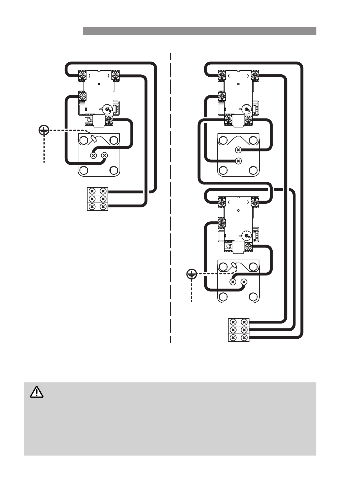
Wiring Diagrams
Thermostat Setting
The thermostat is adjustable from 60°C to 70°C� Turning the adjustment knob anticlockwise decreases the
temperature setting and turning it clockwise increases the temperature setting� The water heater as delivered will
have the thermostat preset to 70°C�
WARNING
EnsurethepowersupplyisswitchedOFFbeforeremovingtheaccesscovertotheelementand
thermostat.
TheaccesscovertotheelementandthermostatMUST ONLY BEremovedbyanElectricianor
othersuitablyqualiedtradesperson.
ThethermostatsettingMUST ONLY BEadjustedbyanelectricianorothersuitablyqualied
trades person.
Afteradjustment,pressthe(red)‘Reset’Buttononthethermostatstoensuretheover-temperature
andenergycut-outisset.
Neutral - N
Off Peak - A
Continuous - A
BOTTOM ELEMENT
TWIN ELEMENT
TOP ELEMENT
3 1
4
5 2
RESET
3 1
4
5 2
RESET
Earth
SINGLE ELEMENT
3 1
4
5 2
Neutral - N
Active - A
RESET
Earth
INSTALLATION

Rinnai 19 EHFA/EHFD HW IM
WARNING
Commissioning activities MUST BEcarriedoutbyanauthorisedperson.
DO NOTswitchontheelectricpowersupplyuntilthewaterheaterislledcompletelywithwater.
TO FILL & TURN ‘ON’ THE WATER HEATER
1� Open all hot water taps in the building, including the shower�
2� Open the cold water isolation valve to water heater� Air will now be forced out of the taps�
3� Close each tap when water runs freely without air bubbles�
4� Check all plumbing connections and pipe work for water leaks�
5� Connect the water heater to the electricity supply, and turn the electric power supply 'ON'�
TO TURN ‘OFF’ THE WATER HEATER
It may be necessary to turn off a water heater after installation and commissioning, for example during building
activities or if the premises are vacant�
1� Isolate or turn 'OFF' the water heater at the electricity supply�
2� Close the cold water isolation valve at the inlet to the water heater�
COMMISSIONING
S110801 20 EHFA/EHFD HW IM Rev� D - 25/09/17
CONTACTS
Australia Pty. Ltd.
ABN 74 005 138 769
Rinnai has a Service and Spare Parts network with personnel who are fully trained
and equipped to give the best service on your Rinnai appliance. If your appliance
requires service, please call our National Help Line. Rinnai recommends that this
appliance be serviced every year.
Head Office
100 Atlantic Drive,
Keysborough VIC 3173
P.O. Box 460
Braeside, Victoria 3195
Product Sales and Service - National
Phone: 1300 555 545* Fax: 1300 555 655*
Technical Helpline and Spare Parts
National (Mon-Fri 8am - 5.30pm EST)
Phone: 1300 555 545* Fax: 1300 300 141*
*Cost of a local call higher from mobile or public phones.
E-mail: [email protected]
For further information visit: www.rinnai.com.au