2
Rinnai Electric Heat Pump Water Heater Manual
DO NOT destroy this manual. Please read the manual and labels thoroughly located on the water
heater before you install, operate, or service it. Consult your manufacturer or your dealer for details
concerning your product. The illustraon on the front cover is for reference only.
WARNING
1. Welcome ............................................................................................................................ 4
1.1 To the Installer and Consumer .................................................................................................4
1.2 For Your Records ......................................................................................................................4
2. Safety .................................................................................................................................. 5
2.1 Read the Safety Informaon ....................................................................................................5
2.2 Safety Precauons....................................................................................................................5
2.3 Relief Valve Warnings ..............................................................................................................7
2.4 Coin Cell baery Warnings .......................................................................................................8
2.5 Addional Precauons .............................................................................................................9
3. Understanding Heat Pump Water Heater ............................................................................. 10
3.1 Operang Principle ..................................................................................................................10
3.2 System Schemac ....................................................................................................................10
4. About the Water Heater ...................................................................................................... 11
4.1 Top View...................................................................................................................................11
4.2 Front View ................................................................................................................................11
4.3 Components .............................................................................................................................12
4.4 General Specicaon ...............................................................................................................12
4.5 Included Items with Unit ..........................................................................................................13
4.6 Accessories ...............................................................................................................................13
5. Installaon Instrucons ....................................................................................................... 14
5.1 Local Installaon Regulaons...................................................................................................14
5.2 Addional Clearances ..............................................................................................................14
5.3 Recommended Locaons for Maximum Energy Saving (Not Ducted) .....................................15
5.4 Inspect Shipment .....................................................................................................................16
5.5 Posioning the Heat Pump ......................................................................................................16
5.6 Thermal Expansion ...................................................................................................................17
5.7 Water Supply Connecons .......................................................................................................17
5.8 Condensate Drain .....................................................................................................................18
5.9 Typical Installaon ...................................................................................................................19
5.10 Relief Valve .............................................................................................................................19
5.11 To Fill the Water Heater ........................................................................................................20
5.12 Electrical Connecon .............................................................................................................20
5.13 Insulaon Blanket ..................................................................................................................23
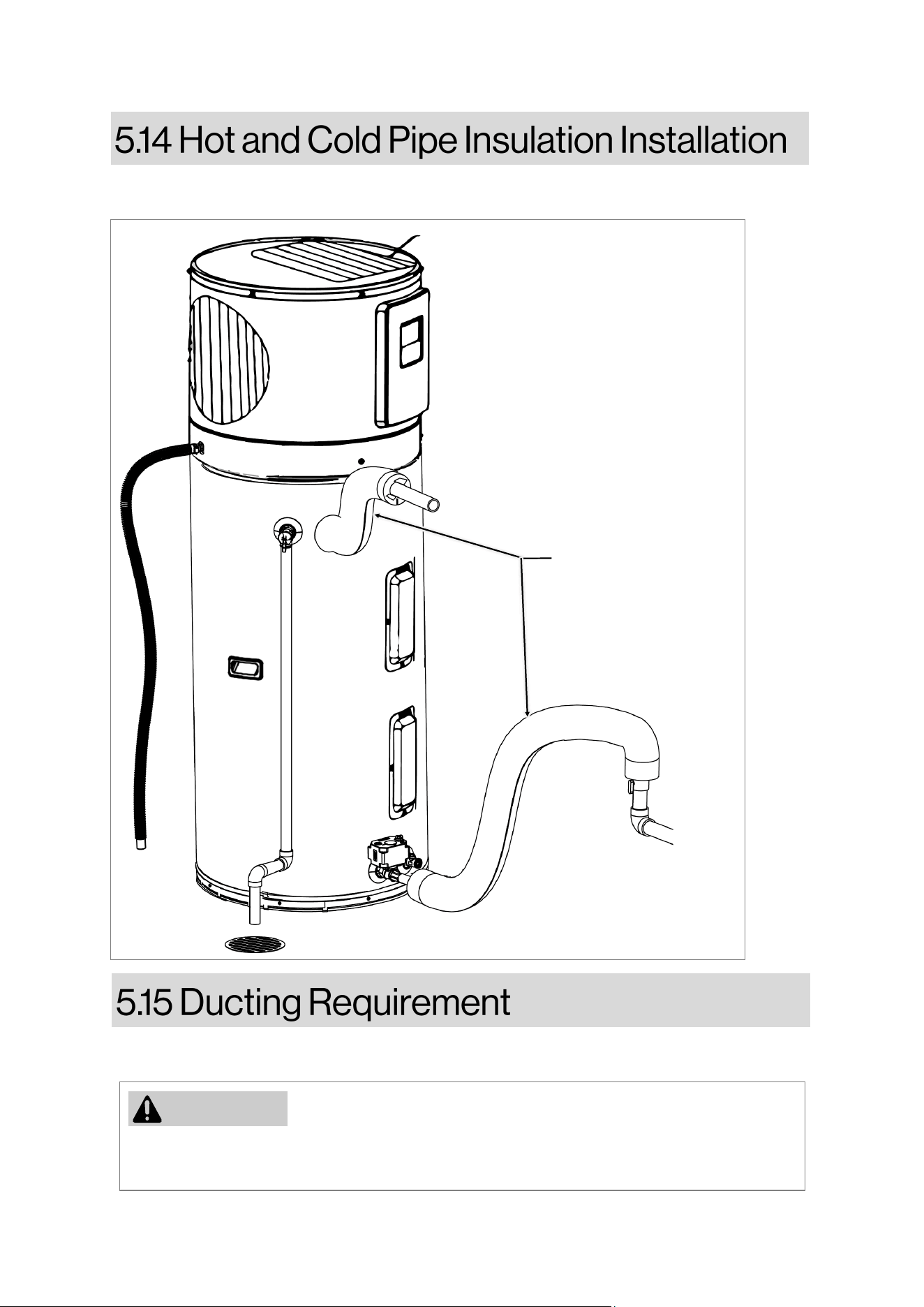
5.14 Hot and Cold Pipe Insulaon Installaon ...............................................................................24
5.15 Ducng Requirement .............................................................................................................24
6. Operang Instrucon ........................................................................................................... 25
6.1 Start-Up Informaon ................................................................................................................25
6.2 Operaon .................................................................................................................................26
6.3 Engineering Channel ................................................................................................................33

3
Rinnai Electric Heat Pump Water Heater Manual
7. Care & Cleaning ................................................................................................................... 35
7.1 Roune Prevenve Care .......................................................................................................... 35
7.2 Draining the Water Heater ...................................................................................................... 35
7.3 Element Heater ........................................................................................................................ 35
7.4 Air Filter Maintenance ............................................................................................................. 36
7.5 Condensate Drain Maintenance .............................................................................................. 36
7.6 TCO Switch Check .................................................................................................................... 36
7.7 Vacaon and Extended Shut-Down ......................................................................................... 36
7.8 Anode Rod Maintenance ......................................................................................................... 36
8. Troubleshoong Tips ........................................................................................................... 37
8.1 Before you Call for Service ....................................................................................................... 37
8.2 Troubleshoong ....................................................................................................................... 37
8.3 Performance Data .................................................................................................................... 38
8.4 Error Codes .............................................................................................................................. 39
9. Customer Service ................................................................................................................. 42
9.1 CTA Module Set-Up .................................................................................................................. 42
9.2 Demand Response (CTA-2045) Installaons ............................................................................ 43
9.3 Replacement Parts ................................................................................................................... 44
9.4 Thermal Cut-o Reset Instrucons .......................................................................................... 46
9.5 Wiring Diagram ....................................................................................................................... 47
9.6 Warranty .................................................................................................................................. 48
4
Rinnai Electric Heat Pump Water Heater Manual
This manual oers the installer essenal recommendaons and basic instrucons for correctly
installing and adjusng the water heater. It provides comprehensive informaon on the features,
operaon, safety precauons, maintenance, and troubleshoong procedures for the owner/
operator. Addionally, a replacement parts list is included in this manual.
It is imperave for the owner/operator to thoroughly read and comprehend the instrucons to
ensure procient adjustment and operaon of the water heater. If there is any diculty in
understanding the instrucons, it is advised to seek professional assistance.
For any inquiries regarding service, warranty, and maintenance maers not addressed in these
instrucons, please direct them to the seller from whom you purchased the product.
Thank you for purchasing a Rinnai Electric Heat Pump Water Heater. Before installing and
operang this water heater, please read these instrucons completely to familiarize yourself with
the water heater’s features and funconality.
Fill out this secon for your records.
Date Purchased:
Model number:
Serial number:
Check the rang plate label located on the front of water heater for model number and serial
number.
Proof of the original purchase date is needed to obtain service under the warranty.
5
Rinnai Electric Heat Pump Water Heater Manual
Idenfy the safety alert symbol,
recognizing it as a sign of
important safety informaon.
This symbol serves to alert you
to potenal hazards that pose a
risk of harm or injury to you and
others.
Indicates an imminently hazardous
situaon which, if not avoided, will result
in personal injury or death.
Indicates an imminently hazardous
situaon which, if not avoided, will result
in personal injury or death.
Indicates a potenally hazardous situaon
which, if not avoided, could result in minor
or moderate injury. It may also be used to
alert against unsafe pracces.
Schedule an appointment with a trained
and qualied professional to install your
water heater.
Incorrect installaon, operaon, or service
can damage the water heater, your house
and other property, and present risks
including re, scalding, electric shock, and
explosion, causing serious injury or death.
Preventave care by owner can maximize
the life of the water heater. Please refer
to CARE & CLEANING secon and
TROUBLESHOOTING TIPS secon. This
may prevent you from making a service
call for your appliance.
WARNING
WARNING
CAUTION
DANGER
All safety messages will follow the safety alert
symbol and either the word “DANGER”,
“WARNING”, “CAUTION” or “NOTICE”.
Aenon is called to observe a specied
procedure or maintain a specic
condion.
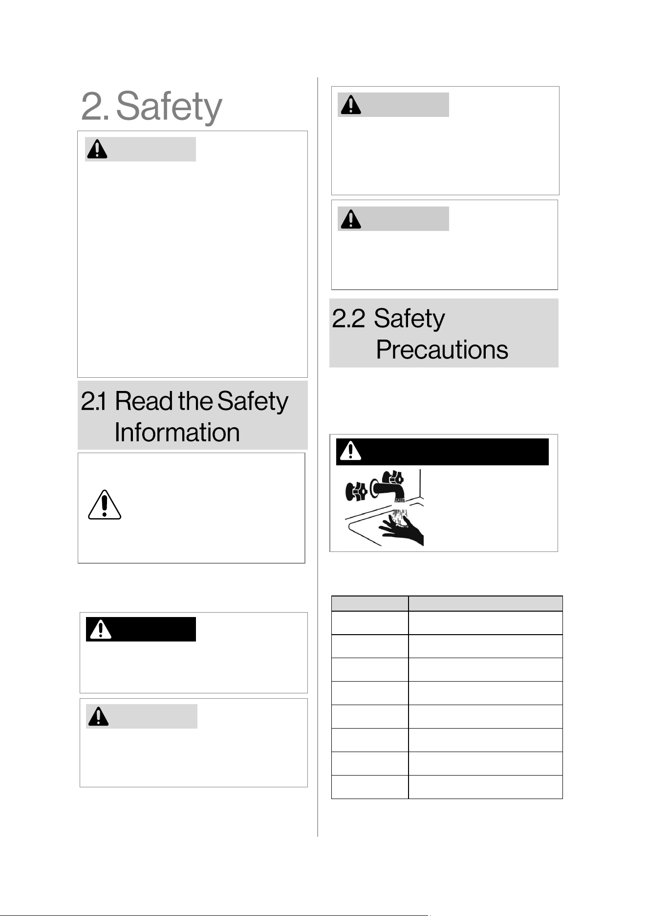
DANGER Scalding Risk
Priorize your safety and that of others. This
manual and your water heater contain
crucial safety messages. Adhere to all safety
instrucons.
Water temperatures
over 125° F (52° C)
can cause severe
burns or scalding
resulng in death.
HOT
BURN
Table 1
Temperature Time To Cause Serious Burns
120°F (49°C) More than 5 minutes
125°F (52°C) 1 1/2 to 2 minutes
130°F (54°C) About 30 seconds
135°F (57°C) About 10 seconds
140°F (60°C) Less than 5 seconds
145°F (63°C) Less than 3 seconds
150°F (65°C) About 1 1/2 seconds
155°F (68°C) About 1 second
Time/Temperature Relaonship in Scalds
NOTICE
6
Rinnai Electric Heat Pump Water Heater Manual
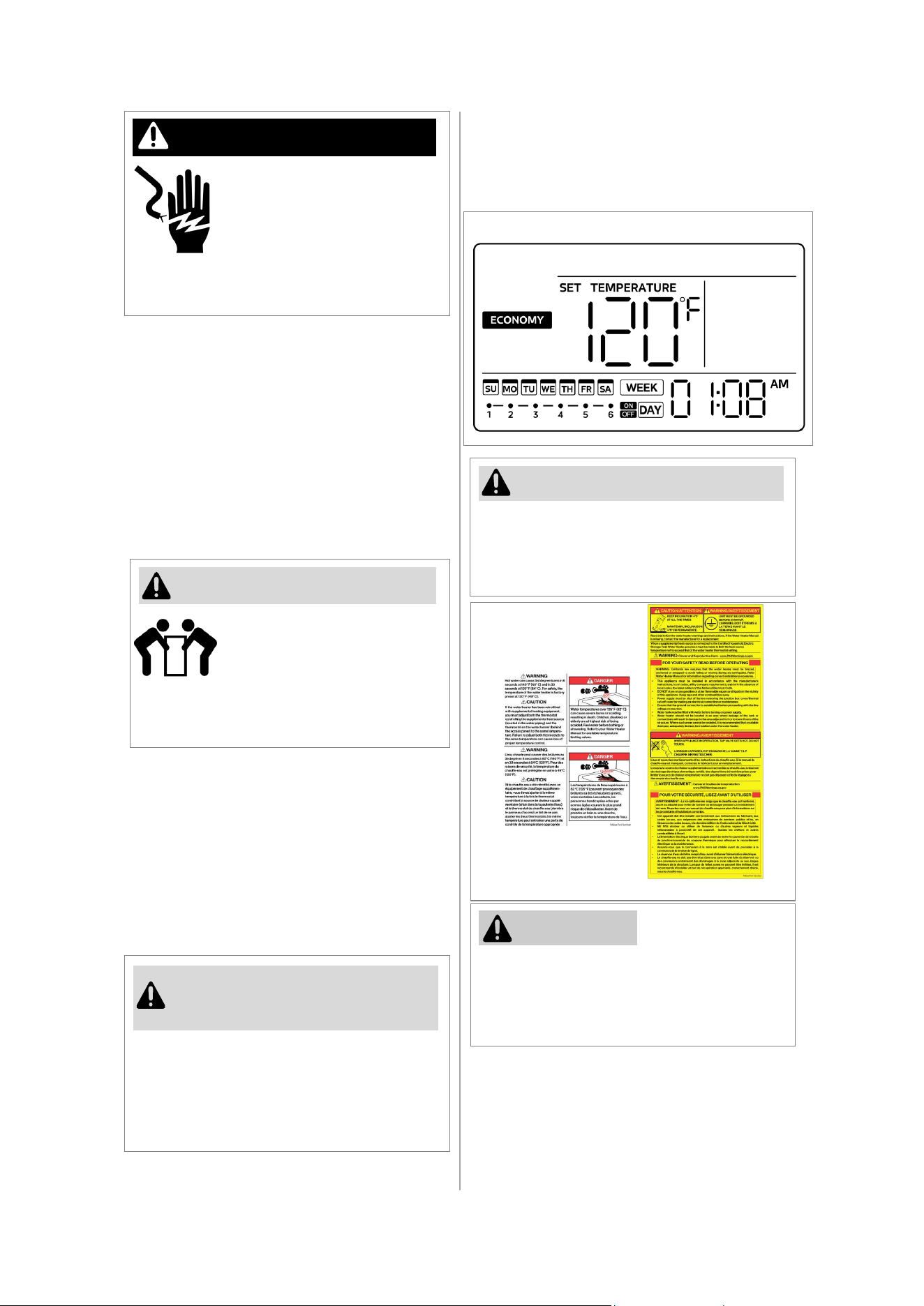
WARNING Liing Risk
As the owner/operator, it is essenal to
thoroughly read and adhere to the warning
instrucons provided on the label Figure 2,
which is also located on the water heater.
Figure 2
WARNING
Contact with the electrical
parts in the juncon box,
behind the juncon box cover
and behind electric heater
cover can result in severe
injury or death from the
electrical shock.
• Disconnect power by opening the circuit
breaker or removing the fuses before
installing or servicing.
• Use a non-contact circuit tester to
conrm that power is o before working
on or near any electrical parts.
• Replace the juncon box cover and
access doors aer servicing.
DANGER Electric Shock
The water heater is heavy.
Follow these precauons to
reduce the risk of property
damage, injuries from liing or
impact injuries from dropping
the water heater
• Use at least two people to li the water
heater.
• Be sure you both have a good grip before
liing.
• Unit is top heavy, use an appliance dolly
(with strap) to move the water heater.
Temperature
Seng
WARNING
• See the Figure 1 for the water default
temperature seng and refer to secon
6.2, page 25
in this manual for details on
adjusng it.
The water heater interface regulates the
temperature of the water. For safety
compliance, the temperature of the water
heater was factory preset at 120°F (49°C)
before it was shipped.
Figure 1
Mixing valves are recommended to lower
water temperature at specic points of use
by blending hot and cold water within
branch water lines.
NOTICE
• It is recommended to install a mixing
valve that meets the requirement in ASSE
1017, the Standard for Temperature
Actuated Mixing Valves for Hot Water
Distribuon Systems.
Warning Label
Scalding Label
7
Rinnai Electric Heat Pump Water Heater Manual
• NEVER block the outlet of the T&P valve
or its drain line for any reason. The T&P
valve MUST be operated at least every 6
months to remove lime deposits and
verify that it is not blocked. Failure to do
this may result in the water heater
failing.
• If the valve does not discharge water
when the easing gear is opened or does
not seal again when the easing gear is
closed, contact qualied and trained
professional to replace the valve. The
T&P valve is not serviceable, it MUST be
replaced.
WARNING
• DO NOT tamper with or remove safety
devices.
• DO NOT operate the water heater
unless all safety devices are ed and
in working order.
• DO NOT block or seal the T&P Valve
and drainpipe.
• DO NOT connect other plumbing to the
T&P plumbing; it must go directly to a
suitable open drain.
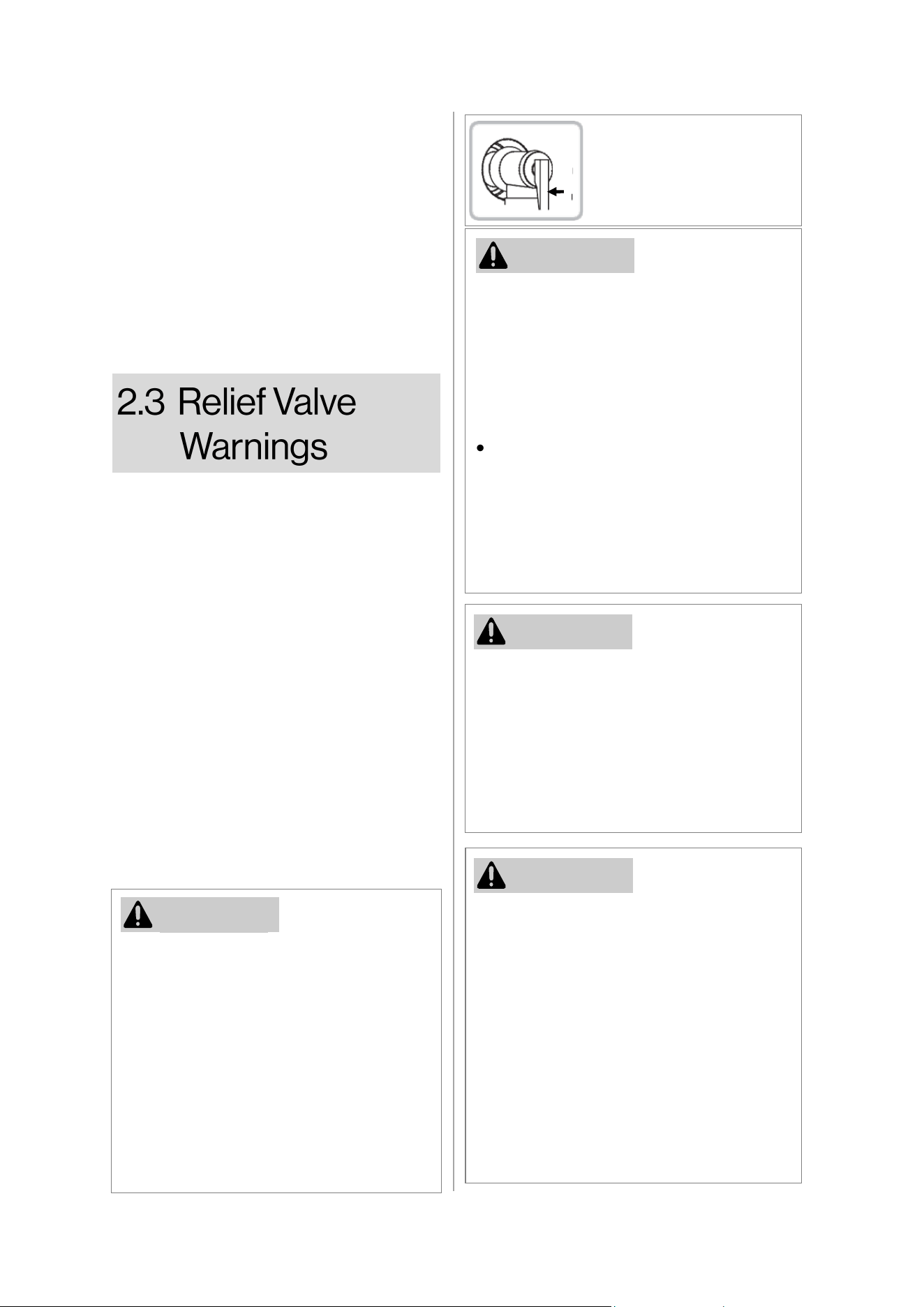
WARNING
To operate T&P valve, li
easing gear unl water ows
from drain line. (Lower gear
gently!)
• NEVER replace the T&P valve with one
which has a higher-pressure rang than is
specied for your water heater.
• The pressure rang of the relief valve
used must not exceed 150 PSI, the
maximum working pressure of the water
heater as marked on the rang plate.
WARNING
• For more detailed informaon, please
refer to Secon 9.2, page 42 for further
assistance, reach out to a licensed
plumber or your local plumbing
authority.
• In demand response applicaons, a
thermostac mixing valve in compliance
with ASSE 1017 must be placed on the
hot water supply line, following all
installaon instrucons provided by the
manufacturer.
Safety Devices
The water heang system is equipped with
temperature sensors, overheat sensors,
switches, Drain valve, and a Temperature &
Pressure Relief (T&P) valve. It is essenal that
these components are not tampered with or
removed. The operaon of the water heang
system should only occur when each of these
devices is correctly installed and funconing.
Temperature & Pressure Relief (T&P) Valve
Please note that this valve is located near the
top of the water heater close to hot water
outlet and is essenal for safe operaon. A
naonally recognized tesng laboratory
maintains periodic inspecon of the valve
producon process and ceres that it meets
the requirements for Relief Valves for Hot
Water Supply Systems, ANSI Z21.22.
WARNING
Prior to installing or operang the water
heater, thoroughly read and comprehend the
enre Manual. Taking the me to do so can
potenally save you both me and expenses.
Pay special aenon to the Safety
Instrucons outlined in the manual, as
neglecng these precauons could lead to
severe bodily harm or fatal consequences. If
you encounter dicules understanding the
instrucons or have any quesons, cease the
installaon or operaon, and seek assistance
from a qualied service technician or your
local electric ulity.
Easing gear
8
Rinnai Electric Heat Pump Water Heater Manual
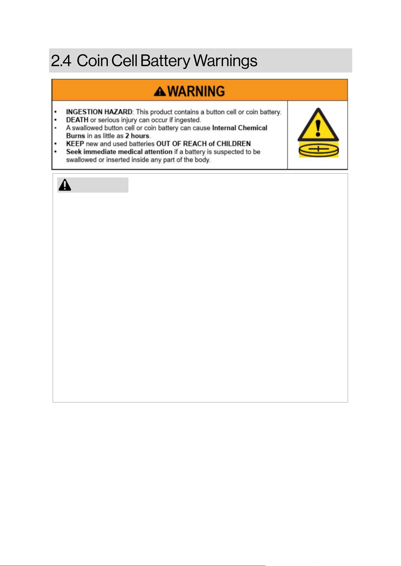
• Remove and immediately recycle or dispose of used baeries according to local regulaons
and keep away from children. Do NOT dispose of baeries in household trash or incinerate.
• Even used baeries may cause severe injury or death.
• Call a local poison control center for treatment informaon.
• Baery type: CR2032
• Baery nominal voltage: 3.0V
• Non-rechargeable baeries are not to be recharged.
• Do not force discharge, recharge, disassemble, heat about 140°F (60°C) or incinerate. Doing
so may result in injury due to venng, leakage or explosion resulng in chemical burns.
• Ensure the baeries are installed correctly according to polarity (+ and -).
• Do not mix old and new baeries, dierent brands of baeries, such as alkaline, carbon-
zinc, or rechargeable baeries.
• Remove and immediately recycle or dispose of baeries from equipment not used for an
extended period of me according to local regulaons.
• Always completely secure the baery compartment. If the baery compartment does not
close securely, stop using product, remove the baeries, and keep them away from
children.
WARNING
9
Rinnai Electric Heat Pump Water Heater Manual
Refrigerant
The Water Heater comes pre-charged with an
environmentally friendly refrigerant, R134A,
which is free from chlorine. This refrigerant
has a zero-ozone depleon potenal.
2. Prior to installing or operang the water
heater, thoroughly review this manual.
3. Ulize this appliance solely for its
intended purpose as outlined in the
Manual.
4. Ensure that your appliance is correctly
installed in compliance with local codes
and the accompanying installaon
instrucons.
5. DO NOT aempt to repair or replace any
component of the water heater unless
explicitly recommended in this manual;
seek the assistance of a qualied
technician for all other servicing.
6. DO NOT aempt to repair or replace the
compressor, refrigerant, or any
component associated with the sealed
refrigerant system.
7. DO NOT acvate the electrical supply or
operate the water heater unless it is
enrely lled with water.
FLAMMABLE CONTENTS UNDER PRESSURE.
The compressor is a non-serviceable
component. Arcing of the compressor wiring
terminals could lead to the release of
pressurized refrigerant and oil, potenally
causing ignion and resulng in severe bodily
injury, severe burns, or even death.
WARNING
Before commencing maintenance, ensure
that all power to the unit is disconnected.
Neglecng to do so may lead to electrical
shock, causing signicant personal injury or
even death.
WARNING
1. Request the installer to demonstrate the
circuit breaker's locaon and how to switch
o the power if necessary. Switch o the
circuit breaker under circumstances such as
overheang, re, ooding, physical dam-
age, or if the TCO (thermal cut-o) fails to
deacvate.
10
Rinnai Electric Heat Pump Water Heater Manual
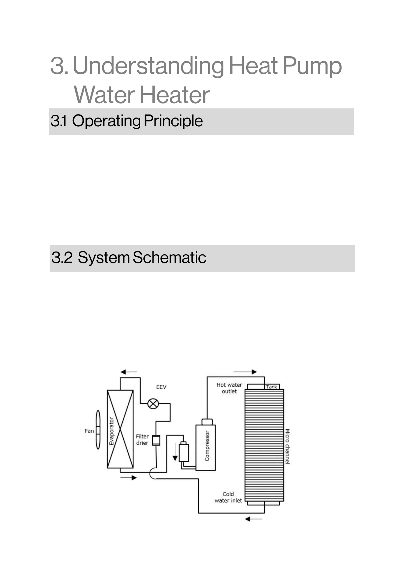
Illustrated in Figure 3, the sealed system within the apparatus is charged with refrigerant. This
refrigerant undergoes evaporaon at low temperatures, extracng heat from the surrounding air.
Within the evaporator, the refrigerant transions from a liquid to a gaseous state. Subsequently, a
compressor elevates the pressure and temperature of the gaseous refrigerant. The energy for
compression, sourced from electricity, is indirectly converted into heat and discharged to the
downstream microchannel (condenser). At this stage, the refrigerant indirectly imparts latent heat
to the water within the Domesc Hot Water (DHW) tank, experiencing a phase change back to a
liquid state. The liquid refrigerant is then directed to a lter dryer, followed by an expansion valve
that diminishes the prevailing pressure. The refrigerant is subsequently guided back to the
evaporator, iniang the cycle again.
Figure 3
The electric heat pump operates in a manner opposite to that of a refrigerator. It extracts heat from
the surrounding outside air and transfers it into the water, using electricity solely for system
operaon. This results in signicantly reduced energy consumpon compared to using an electric
element hot water system alone. The eciency of the heat pump system is enhanced in warmer
climates.
The heat pump unit features a highly ecient micro-channel heat exchanger wrapped around the
inner cylinder to opmize thermal conducvity. A temperature sensor in the tank regulates the
heat pump's operaon to achieve the desired water temperature.
During periods when ambient weather condions are unfavorable for the heat pump operaon or
during peak water demand, the electric element heater takes over to ensure a connuous supply of
hot water.
11
Rinnai Electric Heat Pump Water Heater Manual
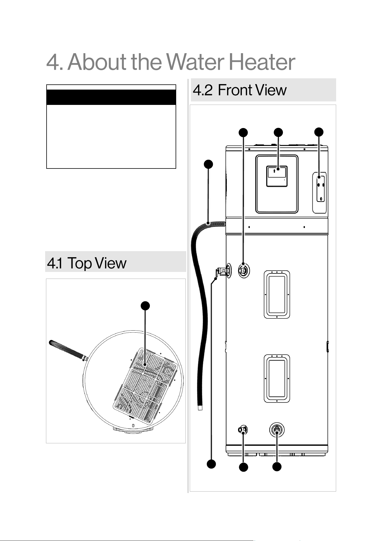
Figure 5
Display
1
Condensate
Drain Pipe
7
CTA-2045
Port
4
Water
Outlet
2
6
3
T&P
Valve
Water
Inlet
5
Drain
Valve
Air Filter
The Rinnai Electric Heat Pump Water Heater
is designed for indoor installation only. The
appliance extracts heat from the ambient air
and provides it to the water in the DHW tank
with added electric power. The amount of
electric energy and time required to heat-up
the DHW depends on the temperature and
humidity of the ambient air.
Topics in this section
• Top View
• Front View
• Components
• General Specifications
• Included Items with Unit
• Accessories
Figure 4
8
12
Rinnai Electric Heat Pump Water Heater Manual
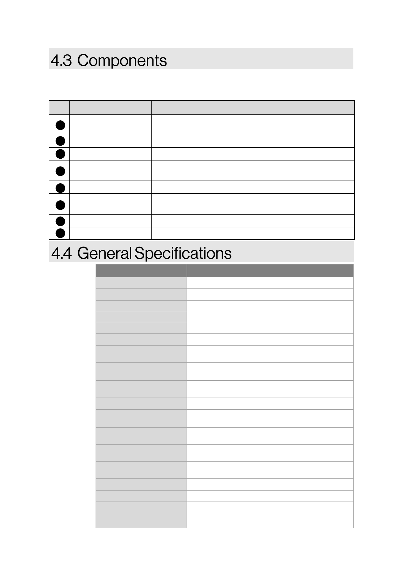
Listed below are descripons of heat pump components. Refer to the previous page for component
illustraon.
Item Name Descripon
Display
The appliance is equipped with 4.1” screen with user friendly
interface and touch panel controller to perform operaons.
Water Outlet Hot water outlet with 3/4” MNPT ng.
Water Inlet
Cold water in with 3/4” MNPT ng.
CTA2045 Port
CTA2045 compliant module can be connected to the water
heater through this port.
Drain Valve Provides easy access to drain the tank during maintenance.
T&P Valve
Automacally releases water when the pressure or temperature
in the tank exceeds safety levels.
Condensate Drain Pipe
A exible 5.2 long pipe provided with unit to drain condensate.
Air Filter Washable air lter lters and eliminates debris from entering.
7
4
5
6
3
2
1
Table 2
Table 3
Model REHP Series (for all models)
Total Unit Waage (Input)
5000 W
Installaon Type
Indoor
Power Supply
208 - 240 V
Electric Breaker Size
30 Amps
Maximum Current
21.5 Amps
Refrigerant Type
R134a
Refrigerant Circuit Max
Pressure
150 PSI (1034 KPa)
Operang Ambient Temp.
for Heat Pump
37~108°F (3~42°C)
Operang Ambient Temp.
for Heang Element
5~115°F (-15~46°C)
Ingress Protecon
IP21
Hot Outlet and Cold Inlet
Water Connecons
3/4” MNPT
Condensate Drain
Connecon
3/4” Male Barb Fing
Temp & Pressure Valve
Pressure Rang
150 PSI (1034 KPa)
Temp & Pressure Valve
Temperature Rang
210°F (99°C)
Cercaons
NEEA, AHRI, ANSI, and UL
Energy Star Cered
Yes
Warranty
Tank & All Other Parts & Components: 10 Years.
Reasonable Labor: 1 Year. See Secon 9.6, page 48
for Complete Details
*Refer to
800000224
(Electric
Heater Pump
Water Heater
Specicaon
Sheet) for
detailed
specicaons
and unit
dimensions.
8
13
Rinnai Electric Heat Pump Water Heater Manual
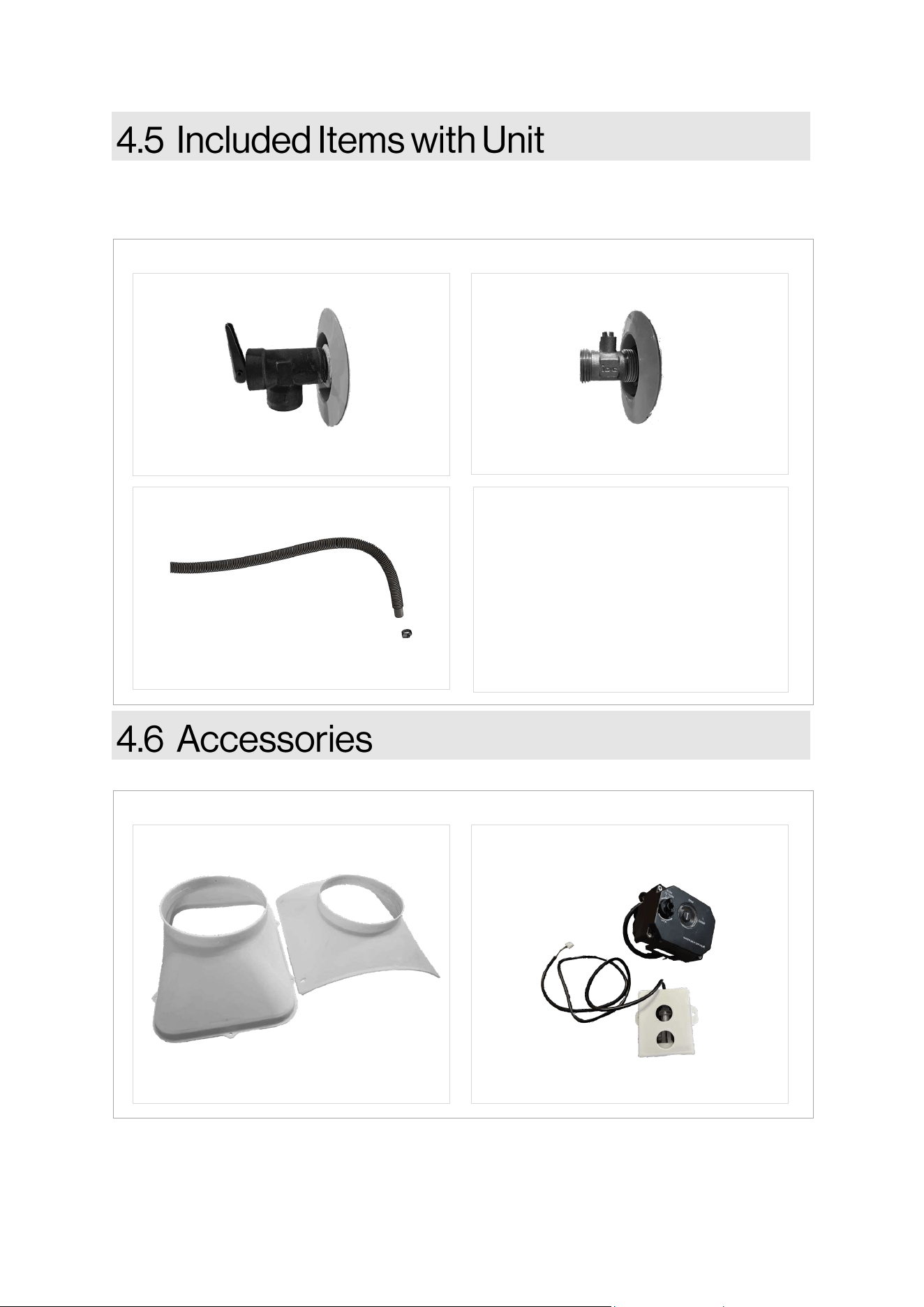
Carefully unpack your water heater and verify the following items are included/preinstalled. If any
items are damaged or missing, contact your local dealer/distributor. Do not aempt to use any
item that appears damaged.
• Installaon and Operaon Manual
(this manual)
DOCUMENTATION
T&P VALVE
PART #: 107000677
Figure 6
DRAIN VALVE
PART #: 107000678
DRAINAGE PIPE
PART #: 107000674
The following oponal accessories are available for the Rinnai Electric Heat Pump Water Heater.
EHPWH DUCTING KIT
PART #: 103000120
Figure 7
EHPWH LEAK KIT
PART #: 103000119
14
Rinnai Electric Heat Pump Water Heater Manual
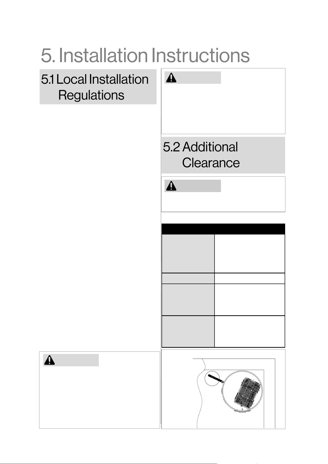
Insucient venlaon in conned spaces
during installaon may result in higher power
consumpon for the unit. It is advisable to
install the water heater in locaons where
ambient temperature is more than 37.4°F (3°C)
and less than 107.6°F (42°C).
NOTICE
Installaon of this water heater must adhere
to these instrucons, local codes, ulity
codes, and ulity company requirements. In
the absence of local codes, compliance with
the latest edion of the Naonal Electrical
Code is mandatory. This code can be
obtained from various local libraries or
purchased from the Naonal Fire Protecon
Associaon at Baery March Park, Quincy,
MA 02269, in the form of the ANSI/NFPA 70
booklet.
For Canadian installaons, reference to
CSA22.1. A copy can be acquired from the
Canadian Standards Associaon at 5050
Spectrum Way, Mississauga, ONT L4W 5N6.
Locaon
Idenfy a clean, dry locaon for your water
heater and posion it as close as possible to
the area with the highest demand for heated
water. It's important to note that extended,
uninsulated hot water lines can result in
energy and water wastage. Ensure that the
water heater is situated in a way that allows
easy removal of the heang element cover
for inspecon and servicing, such as element
removal or control checks. Protect the water
heater and water lines from freezing
temperatures; avoid installing the water
heater in outdoor, unprotected areas. Verify
that the oor beneath the water heater is
robust enough to support the weight of the
lled water heater.
CAUTION
The water heater should not be located in an
area where leakage of the tank or
connecons will result in damage to the area
adjacent to it or to lower oors of the
structure. Where such areas cannot be
avoided, it is recommended that a suitable
drain pan, adequately drained, be installed
under the water heater.
Table 4
Figure 8
Wall
Wall
Front
Side
Top View
Locaon Addional Clearance
Top 0 in.
Recommended clearance
for opmal eciency &
servicing is 20 in. (508mm)
on the top
Back 0 in.
Le Side 6 in. (152 mm)
Recommended clearance
for servicing is 12 in. (305
mm) on the sides
Right Side 2 in. (51 mm)
Recommended clearance
for servicing is 12 in. (305
mm) on the sides
If addional clearances are not met, damage to
the property and water heater may occur.
CAUTION
15
Rinnai Electric Heat Pump Water Heater Manual
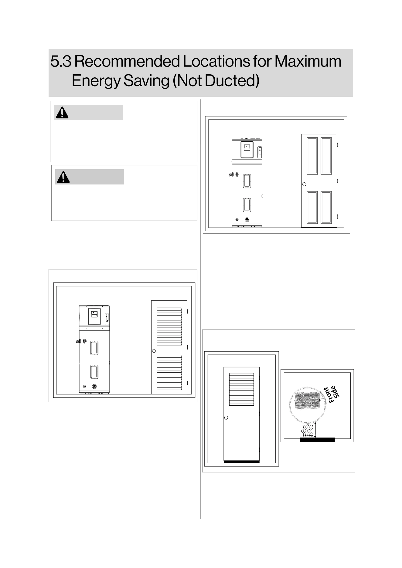
Figure 9
Figure 10
Front View
If air temperature in installed locaon drops
more than 15°F (8°C) during heang, air
circulaon is insucient for ecient
operaon.
NOTICE
No Addional Venlaon Needed:
For room size: Larger than 700
3
(i.e. 7’ X 10’
X 10’). Illustrated in Figure 10.
Addional Venlaon Needed:
For room size: Smaller than 700
3
(i.e. 7’ X 10’
X 10’). Full louvered door required as shown in
Figure 9.
Laundry room or similar:
• 24 in
2
of air gap should be provided under
the door for inlet air.
• Louver on the door must be located as the
same height of air exhaust on the water
heater.
• Water heater air exhaust must be posi-
oned towards louver side within 12 inch
from the door as shown in Figure 11.
Door
Top View
Figure 11
Front View
Front View
12” Max.
For installaon in a room smaller than 700
3
, fully louvered door or ducng should be
installed for ecient operaon.
NOTICE
16
Rinnai Electric Heat Pump Water Heater Manual
• Arrive at site and conduct a safety audit. Safety audits can also be known as Work Method
Statements (WMS) or Job Site Analysis (JSA).
• Park your vehicle as close as allowable to your installaon. Unload all materials in a safe
manner.
• Posion all materials in a convenient posion near the work area.
• This heat pump water heater MUST be installed indoors.
• Adequate access MUST be available to the T&P valve and an anode rod.
• Safely posion the new unit on a level surface in accordance with all plumbing and building
regulaons.
• A suitable drain pan (Figure 13) MUST be used with EHPWH leak kit (sold separately) where
property damage could occur from water spillage.
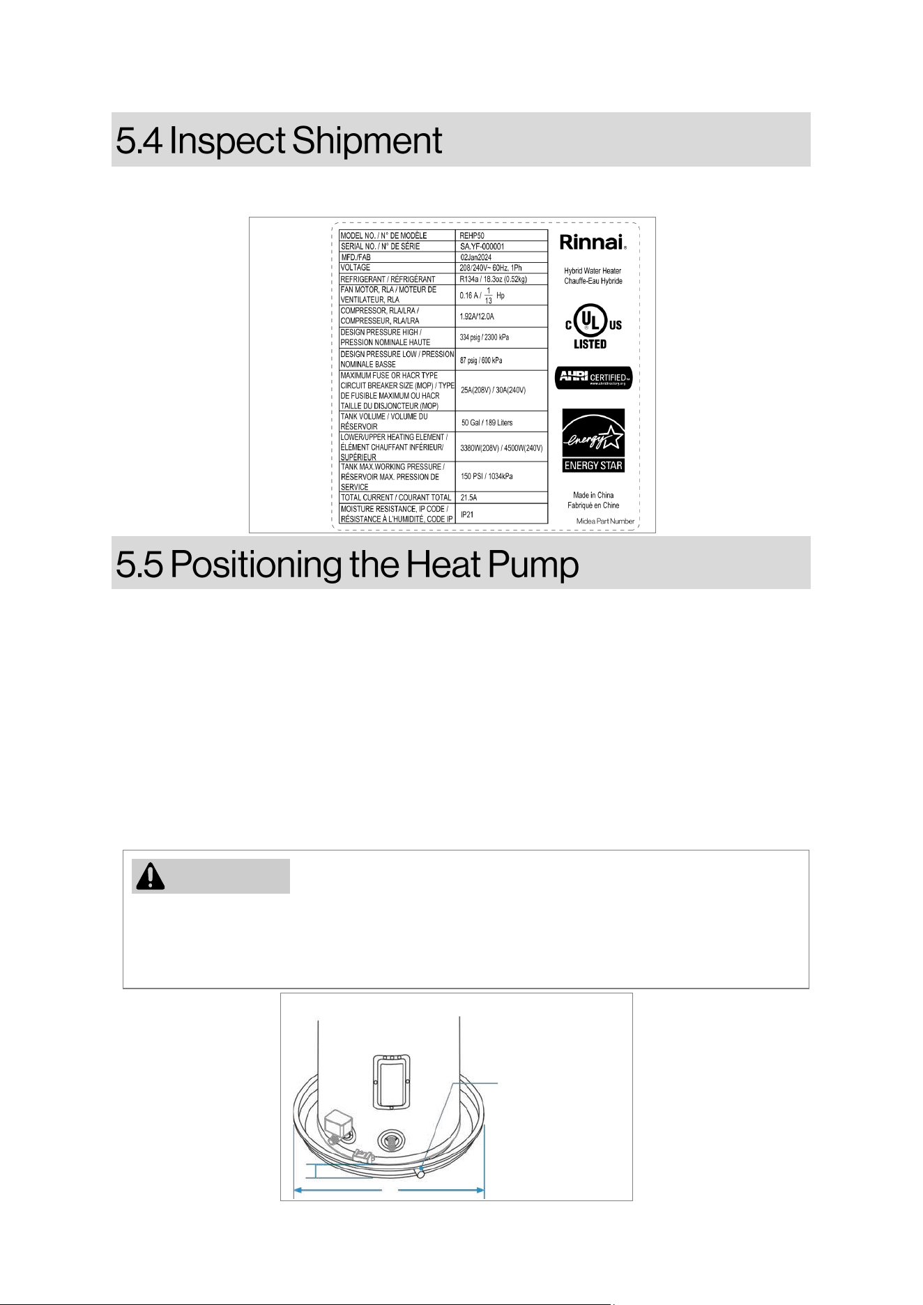
Examine the water heater for damage and verify that the power supply matches the unit's
requirements, as indicated on the rang plate (Figure 12) located on the front of the water heater.
Figure 13
B - Maximum 2”
A
B
A - Diameter of water
heater plus 4” min.
The drain line
should be at
least 3/4” ID
and pitched
for proper
drainage.
Figure 12
NOTICE
The auxiliary drain pan installaon MUST conform to local codes. Drain Pan Kits are available
from the store where the water heater was purchased, or any water heater distribuon. The
Drain Pan should not block the cold inlet or the drain valve. Ensure the oor beneath the water
heater can support its lled weight adequately.
17
Rinnai Electric Heat Pump Water Heater Manual
Please consult the illustraon on Figure 12 for a recommended standard installaon. It is
advisable to use exible connectors for the hot and cold-water connecons. These connectors
oer vibraon isolaon and facilitate easy service of the water heater, if required.
The HOT and COLD water connecons are disnctly labeled and measure 3/4” MNPT on all
models. It is recommended to install a shut-o valve in the cold-water line near the water heater.
Refer to Secon 5.11, page 20 for instrucons on how to ll the water heater.
Verify the presence of a check valve in the incoming water line by consulng your local water
ulity. It might be installed independently as a backow preventer in the cold-water line or
integrated into a pressure reducing valve, water meter, or water soener. A check valve in the
cold-water inlet line can establish a "closed water system," while the absence of such a valve or
backow prevenon device characterizes an "open" water system.
When water is heated, it undergoes thermal expansion, increasing pressure in the water system. In
an "open" water system, excess expanded water returns to the city main, where pressure is easily
dissipated. Conversely, a "closed water system" inhibits expanded water from owing back into the
main supply line, leading to a swi and hazardous pressure rise in the water heater and system
piping. This rapid pressure increase may trigger the T&P valve at each heang cycle.
The connuous expansion and contracon due to thermal expansion can prematurely damage the
T&P valve and potenally the heater itself. Simply replacing the T&P valve will not resolve the
issue. To control thermal expansion, it is recommended to install a correctly sized expansion tank
in the cold-water line between the water heater and the check valve. The expansion tank has an
integrated air cushion that compresses with rising system pressure, alleviang overpressure
condions and prevenng repeated relief valve acvaon. Alternave methods for managing
thermal expansion exist; consult your installaon contractor, water supplier, or plumbing inspector
for more informaon on this maer.
NOTICE
DO NOT apply heat to the HOT or COLD water connecons. If sweat connecons are employed,
sweat the tubing to the adapter before ng the adapter to the water connecons on the heater.
Any heat applied to the water supply ngs will result in permanent damage to the dip tube and/
or heat traps.
NOTICE
• Operang temperature range of cold (inlet) water is 48°F (9°C) to 110°F (43°C).
• Operang pressure range is 43.5 psi (300 kPa) to 150 psi (1034 kPa).
• Water ow rate should be from 0.88 gpm (0.2 m
3
/h) to 3.08 gpm (0.7 m
3
/h).
CAUTION
This appliance must be permanently connected to the water mains. Hose-sets must not be used as
water supply connecons.
18
Rinnai Electric Heat Pump Water Heater Manual
Please check local codes or ordinances for precise specicaons.
IMPORTANT: When making drain ng connecons to the drain tubing, use a clamp to secure.
IMPORTANT: Avoid overghtening when making drain ng connecons to the drain tubing, as it
may lead to product damage and leaks.
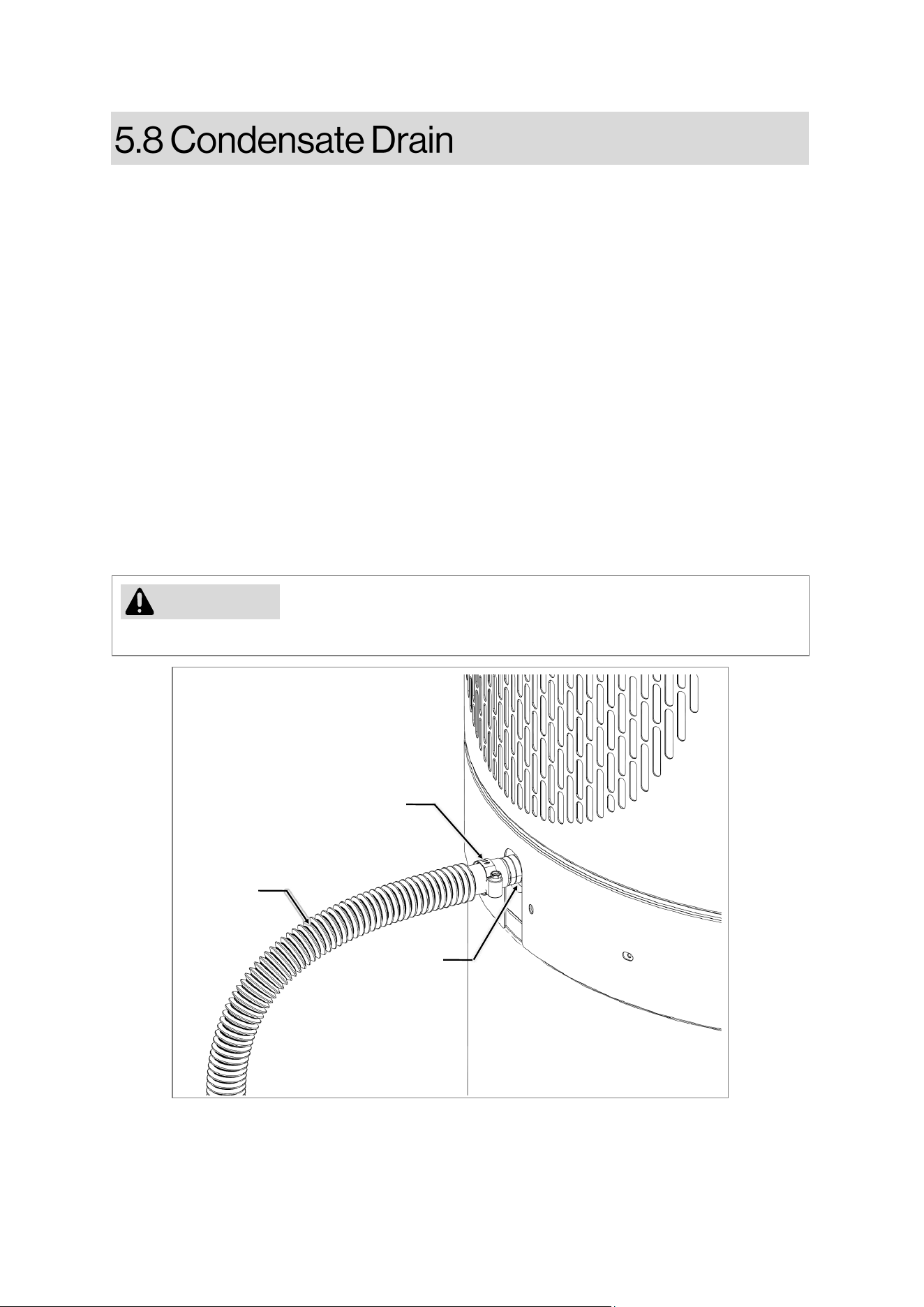
• Flexible drainage pipe with a clamp is provided with the unit.
• Drainage connecon is built-in with the unit.
• DO NOT reduce drain line size less than connecon size provided on condensate
drain.
• All drain lines must be pitched downward away from the unit a minimum of 1/8” per
foot of line to ensure proper drainage.
• Drain lines must include a P-trap if connected to a sewer pipe.
•
If no drain is available, then a common condensate pump with a capacity of no
less than 2 gallon per day must be installed.
• DO NOT allow condensate to drain into the water heater drain pan.
•
The drain line should be insulated where necessary to prevent sweang and
damage due to condensate forming on the outside surface of the line.
NOTICE
The condensate produced by this unit is non-acidic and does not require a condensate neutralizer.
Figure 14
Clamp
(Provided)
Flexible
Drainage
Pipe
(Provided)
Drainage
Connecon
19
Rinnai Electric Heat Pump Water Heater Manual
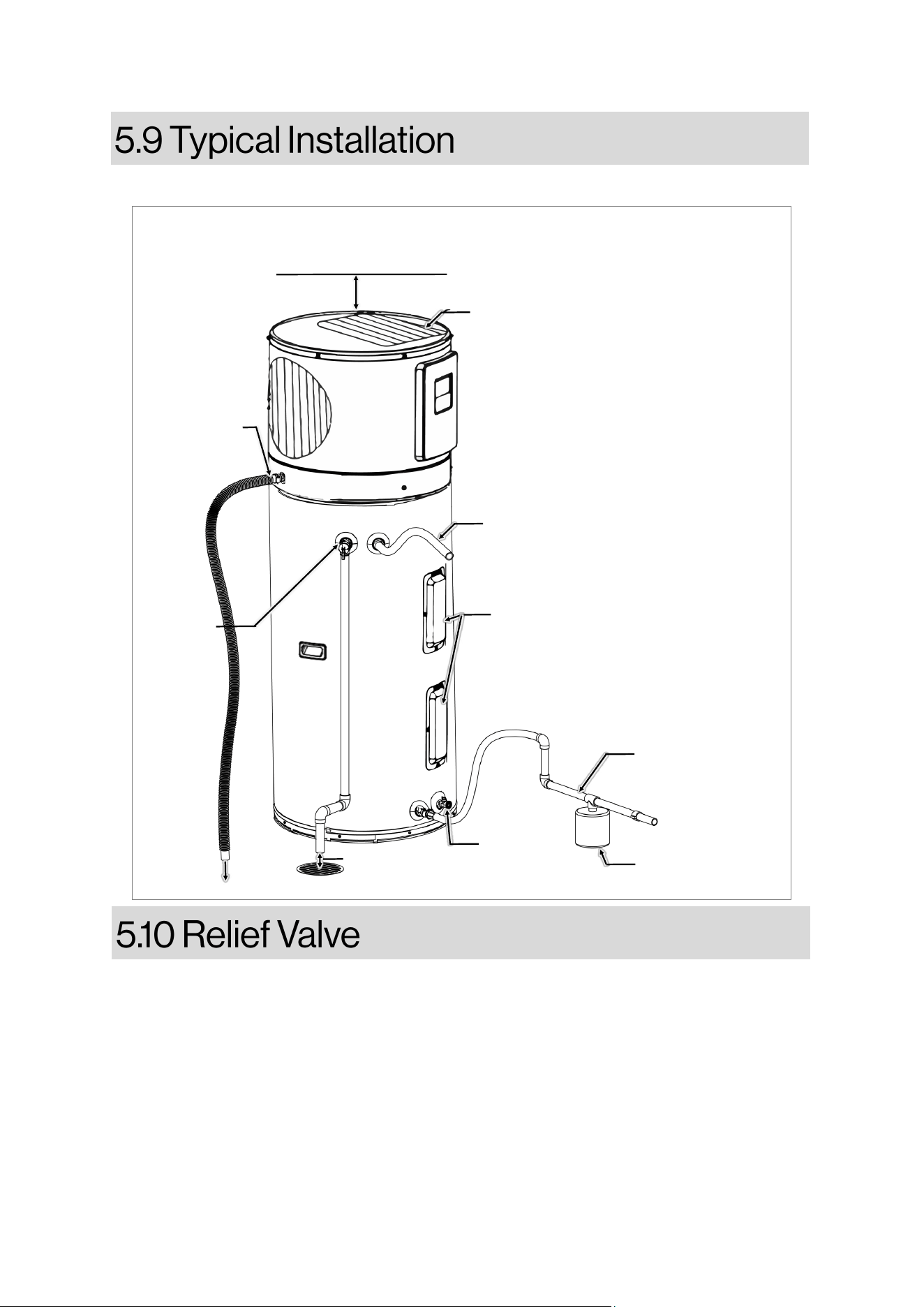
Figure 15
Hot Water Outlet to
xtures (eld supplied)
(Flexible Connecon
recommended)
Air lter (pre-installed)
6 in. (152 mm)
Clearance for servicing is 24
in. (610mm) on the top
6” Air gap
Cold Water Supply
(eld supplied)
(Flexible Connecon
recommended)
Drain Valve
(pre-installed)
Thermal Expansion
Tank (eld supplied)
T&P Valve
(pre-
installed)
Flexible
Condensate
drain piping
for easy
access for
maintenance
(provided)
To Drain
Heang Element Cover
(pre-installed)
Figure 15 illustrates the recommended typical installaon of water heater.
• A newly installed temperature and pressure relief (T&P) valve, meeng the standards outlined
in ANSI Z21.22/CSA 4.4 for Relief Valves in Hot Water Supply Systems, is factory-installed. It
must remain in the designated opening, clearly marked for this purpose, on the water heater.
No valves of any kind should be placed between the relief valve and the tank.
• The T&P discharge piping must be of a type approved for hot water distribuon. The discharge
pipe must be no smaller than the outlet of the T&P valve and must pitch downward from the
valve to allow complete drainage (by gravity) of the relief valve and discharge pipe. The end of
the discharge pipe should not be threaded or concealed and should be protected from
freezing. No valve of any type, restricon or reducer coupling should be installed in the
discharge piping.
20
Rinnai Electric Heat Pump Water Heater Manual
The pressure rang of the relief valve must not exceed 150 PSI, the maximum working pressure of
the water heater as marked on the rang place.
WARNING
Ensure the drain valve on the water heater is fully closed. Proceed to open the shut-o valve in the
cold-water supply line.
Gradually open each hot water faucet to enable the release of air from the water heater and
piping.
If there is a connuous and steady ow of water from the hot water faucet(s), it indicates that the
water heater is enrely lled.
WARNING
Failure to adhere to the instrucons outlined in this manual may result in permanent damage to
the unit and could void the manufacturer's warranty.
WARNING
DO NOT acvate the electrical supply or operate this water heater unless it is enrely lled with
water. The water heater must be lled with water before being turned on. Please note that the
water heater warranty does not cover damage or failure resulng from operaon with an empty
or parally empty tank
.
WARNING
DO NOT link any other plumbing to the T&P plumbing; it must be directly connected to a
suitable open drain. DO NOT join the T&P plumbing with the condensate plumbing.
WARNING
Prior to making any electrical connecons, be sure to turn o the electric power at the fuse box
or service panel. Addionally, ensure that the ground connecon is established before
proceeding with line voltage connecons. Neglecng to follow these steps can lead to electrical
shock, resulng in severe personal injury or death.
Before commencing maintenance, it is crucial to disconnect all power to the unit. Failure to do
so can result in electrical shock, leading to severe personal injury or death. Addionally, ensure
that the unit is grounded, as failure to do so can also cause electrical shock, resulng in severe
personal injury or death.
DO NOT operate the water heater again if it has been exposed to re, ood, or physical damage,
unl it has been inspected by a qualied service technician.
21
Rinnai Electric Heat Pump Water Heater Manual
NOTICE
DO NOT use this appliance if any part has been submerged in water. Contact a qualied installer
or service agency promptly to replace the water heater that has been exposed to ooding. DO
NOT aempt to repair the unit! It must be replaced.
A qualied electrician must establish a separate branch circuit equipped with copper conductors,
an overcurrent protecve device, and appropriate disconnecng means. All wiring must adhere to
local codes or the latest edion of the Naonal Electrical Code ANSI/NFPA 70.
The water heater is fully connected to the juncon box located inside the jacket at the top front of
the unit. A knockout is provided on juncon box cover for electrical ng is available for eld
wiring connecons. The voltage requirements and waage load for the water heater are detailed
on the rang plate situated on the front of the unit.
Grounding instrucon:
1. Ulize metallic conduit or metallic sheathed cable approved for use as a grounding conductor,
installed with ngs approved for this purpose.
2. If non-metallic sheathed cable, metallic conduit, or metallic sheathed cable not approved for
use as a ground conductor is employed, it must incorporate a separate conductor for
grounding. This grounding conductor should be connected to the ground terminals of both
the water heater and the electrical distribuon box.
3. The unit must be installed with a circuit breaker (including GFCI type) near the power supply
and must be eecvely earthed.
4. For wiring diagram, refer to Secon 9.5, page 47.
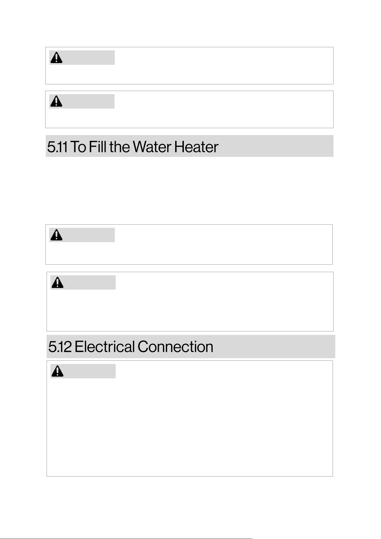
Step to make Electrical Connecon:
1. Locate the terminal block on top right side on water heater behind the juncon box cover.
2. If CTA-2045 module is installed, remove the module to gain access of juncon box cover.
3. Remove 3 screws to disassemble the juncon box cover as shown in Figure 16.
4. Juncon box comes with a 7/16” knockout to pass conduit cable through it.
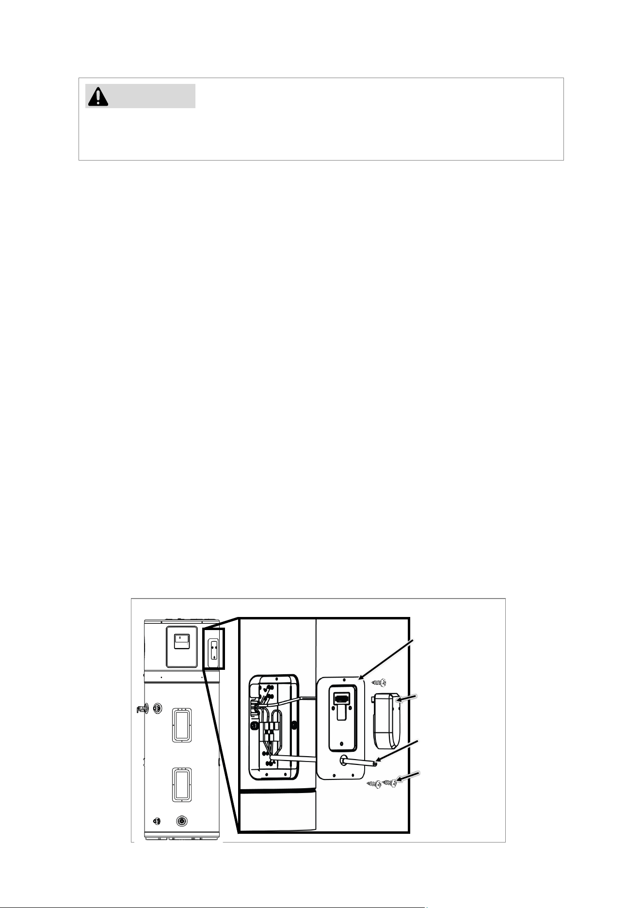
5. As shown in Figure 17, connect Line 1 (L1), Line 2 (L2) and ground wire on the terminal block.
6. Mount back the juncon box cover.
Juncon Box Access
Juncon
Box Cover
Conduit
Connector
Figure 16
3 X Screws
CTA-2045
Module
(Not supplied)
22
Rinnai Electric Heat Pump Water Heater Manual
CAUTION
Table 5
Grounding
Screw
L1 Wire
Connecon
(Black)
Figure 17
WARNING
The water heater and water pipes are not enough for eecve grounding. Components like non-
metallic piping, dielectric unions, and exible connectors may electrically isolate the water
heater.
NOTICE
This guide suggests the minimum branch circuit sizing and wire size in accordance with the
Naonal Electric Code. Please consult the wiring diagrams provided in this manual for details on
eld wiring connecons.
Branch Circuit Sizing and Wire Size Guide - Single Phase Wiring
Total Water Heater
Waage
Recommended Over
Current Protecon (Fuse or
Circuit Breaker Amperage
Rang)
Copper Wire Size
AWG Based on NE.C
Table 310-16 (75°C)
240V 240V
2250 15 14
2750 15 14
3000 20 12
4000 25 10
5000 30 10
5500 30 10
NOTE: When sizing the breaker and wire for over current protecon, include an addional 500W to
the upper element waage rang. This will account for the maximum amperage draw of the
compressor and fan motor.
Ground Wire
Connecon
(Green/Yellow)
L2 Wire
Connecon
(Red)
Juncon Box Details
23
Rinnai Electric Heat Pump Water Heater Manual
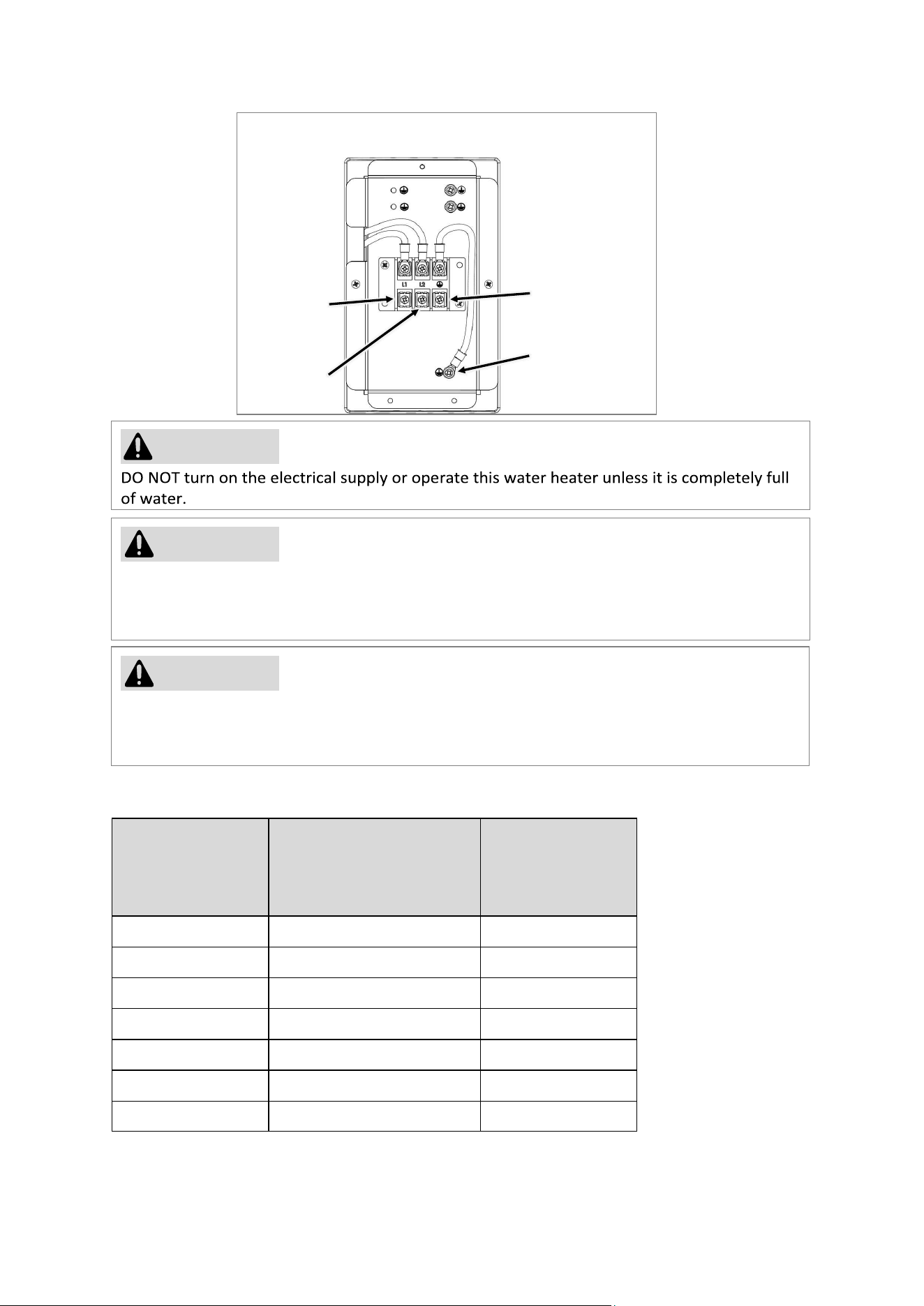
Figure 18
If local codes require external applicaon of insulaon blanket kits the, manufacturer’s
instrucons included with the kit must be carefully followed.
WARNING
Insulaon blankets designed for external use on electric water heaters, which are readily available
to the general public, are not deemed necessary. The primary funcon of an insulaon blanket is
to minimize standby heat loss commonly associated with storage tank heaters. In the case of this
water heater, it either meets or exceeds the insulaon and standby loss requirements outlined by
the Naonal Appliance Energy Conservaon Act standards, rendering the use of an insulaon
blanket unnecessary.
It is important to note that the manufacturer's warranty does not cover any damage or defects
resulng from the installaon, aachment, or use of any energy-saving or other unapproved
devices - excluding those explicitly authorized by the manufacturer - incorporated into, onto, or in
conjuncon with the water heater. The ulizaon of unauthorized energy-saving devices may
compromise the lifespan of the water heater and pose risks to life and property. The manufacturer
explicitly disclaims any responsibility for losses or injuries resulng from the use of such
unauthorized devices.
If local codes mandate the use of an external insulaon blanket for this water heater, it is essenal
to meculously observe the following guidelines to avoid impeding the proper funcon and
operaon of the water heater.
CAUTION
• DO NOT obstruct or cover the operang or warning labels axed to the water heater.
• DO NOT aempt to reposion any labels on the exterior of the insulaon blanket.
• DO NOT block the air openings on top and le side of the water heater.
• DO NOT conceal the Controller Assembly, T&P valve, or drain valve.
• Frequently inspect the insulaon blanket.
Display &
Controller
Air Outlet
Opening
Horizontal Air Fil-
ter (20” Clearance
recommended on
top)
24
Rinnai Electric Heat Pump Water Heater Manual
Figure 19
Insulated Hot and Cold
Water Piping
(Flexible Connecon
recommended)
Install pipe insulaon on the cold water supply inlet and the hot water outlet as shown in Figure
19.
Please refer a separate instrucons provided with EHPWH Ducng Kit - 103000120 (Accessory)
for all ducng requirements.
DO NOT skip the ducng requirement document if any kind of ducng is installed. Ducng
installaon must follow all ducng requirements as menoned in the separate instrucons.
NOTICE
25
Rinnai Electric Heat Pump Water Heater Manual
CAUTION
Hydrogen gas has the potenal to accumulate in a hot water system when the water heater has
remained unused for an extended period, typically two weeks or more. It's crucial to be aware
that HYDROGEN GAS IS EXTREMELY FLAMMABLE!
To migate the risk of injury and disperse any accumulated gas, it is strongly recommended to
open the hot water faucet at the kitchen sink for several minutes before using any electrical
appliances connected to the hot water system. If hydrogen is present, you may hear an unusual
sound resembling air escaping through the pipes as the water begins to ow. It is imperave
that during this process, NO smoking or open ames are allowed near the open faucet. Exercise
cauon and priorize safety.
Safety Precauons
• If the water heater has been exposed to overheang, re, ood, or physical damage, ensure all
power is disconnected.
• DO NOT aempt to turn on the water heater unless it is properly lled with water.
• DO NOT acvate the water heater if the shut-o valve for the cold water supply is closed.
• In case of challenges comprehending or adhering to the Operang Instrucons or the Care and
Cleaning secon, it is advisable to seek the assistance of a qualied individual or service
technician.
If the water heater has been subjected to re, ood or physical damage, disconnect all power to
water heater, and DO NOT operate the water heater again unl it has been checked by a qualied
service technician.
WARNING
DO NOT use this appliance if any part has been submerged in water. Contact a qualied installer
or service agency promptly to replace the water heater that has been exposed to ooding. DO
NOT aempt to repair the unit! It must be replaced.
NOTICE
Safety Controls
The water heater features a thermal cut-o (TCO) posioned near the upper heang element,
making contact with the tank surface. If the water temperature becomes too high, the TCO
interrupts the power supply to the heang element. Aer acvaon, it requires manual
reseng. Refer Secon 9.4, page 46 for reseng instrucons.
A qualied service technician must invesgate the cause of high-temperature and take correcve
acons before pung the water heater back into operaon.
CAUTION
26
Rinnai Electric Heat Pump Water Heater Manual
DANGER
Seng the thermostat too high can create a scalding risk. Homes with young children, the elderly,
or individuals with disabilies may need to set the thermostat to 120°F (49°C) or lower to avoid
exposure to hot water.
Water Temperature Seng
Regulate your water heater's temperature through the control display, keeping safety and energy
savings in mind. Lower sengs reduce energy costs. For safety, the factory default is 120°F (49°C),
which is the recommended starng point. Temperatures above 125°F (52°C) can cause severe
burns. Always follow the manual and label warnings on the front of the heater.
Consider installing mixing valves to blend hot and cold water for safer point-of-use temperatures,
following ASSE 1017 standards. For demand response, use ASSE 1017-compliant thermostac
mixing valves on the hot water supply line, per manufacturer instrucons. Refer Table 1, page 5 to
determine the right water temperature for your home.
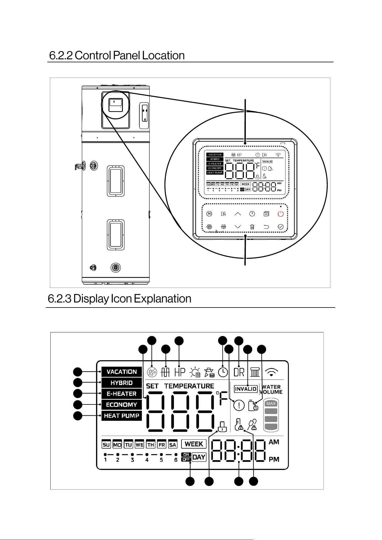
• The primary funcon of the control panel is to allow user to set temperature. Addionally, it
provides access to extra features like seng up schedule, check performance data, show
error codes, update engineering channels etc.
• The water heater has three means of heang the water: the elements, the heat pump, and a
combinaon of the elements and heat pump.
• The control logic of the Control Assembly is designed so that the heat pump always has
priority over the elements. The temperature regulaon will not be performed unl aer Dry-
Fire detecon tesng indicates that there is sucient water in the tank.
• Refer table 6 and 7 to understand display icons and available operaons on this appliance.
The heat pump’s fan will not turn on if the incoming water temperature is less than 39°F (4°C)
and/or the ambient air temperature is above 107.6°F (42°C), or below 37.4°F (3°C). The
internal diagnoscs detects that the heat pump is out of operaonal range.
NOTICE
27
Rinnai Electric Heat Pump Water Heater Manual
Operaon
Display
Figure 21
1
2 3
11
4
5
6
7
8
9
10
12
13
14
15
16
17
18
Figure 20
As
shown in Figure 20, control panel is located on top side on water heater.
Figure 21 shows all the available icons on the display. Refer Table 6 for detailed explanaon of
each icon.
28
Rinnai Electric Heat Pump Water Heater Manual
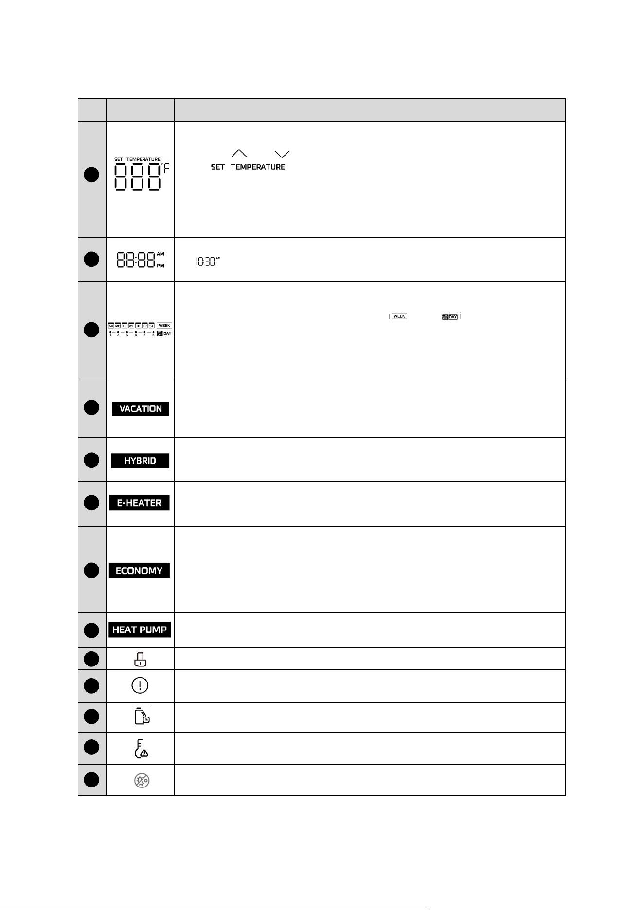
No Icon Descripon
•
Normally, it shows tank water temperature.
•
When “ ” or “ ” arrows pressed, it shows set temperature .
( “Set Temperature” on top side lights up)
•
On VACATION mode, it shows remaining days of vacaon modes.
•
It shows seng temperature on seng.
•
It shows unit seng/running parameters or error/protecon code
on performance data.
Time and clock seng
•
shows the clock.
•
Whenever there is any seng for clock, SET TIME will be lightened.
• There are daily or weekly TIMER icon.
• If anyone of them has been set, either “ ” or “ ” shows up.
• It remains empty if none of the mer is set.
• While seng up a mer, the corresponding icon ashes every 2
seconds to indicate it has been selected.
VACATION MODE:
When set to VACATION mode, the water tank is set at 59°F (15°C), maintains
low tank water temperature, preheats hot water and an-freeze lines, while
reducing on/o operaon of the tank.
HYBRID MODE:
Operang in HYBRID mode, the electric heater and heat pump run together to
fulll hot water demand.
Table 6
1
2
3
4
5
E-HEATER MODE:
When set to E-HEATER mode, only electric heater runs and provides hot
water.
ECONOMY MODE: (Default)
When set to ECONOMY mode, the heat pump and electric heater run together
with higher priority to heat pump to fulll hot water demand. Electric heater
turns on only when the hot water demand gets extremely high.
It is recommended to use this mode to maximize electricity cost savings.
HEAT PUMP MODE:
When set to HEAT PUMP mode, only heat pump will run to provide hot water.
Indicates when child lock funcon is enable. Locks all operaonal buons.
Protecon/Error:
It lights up when the appliance is under protecon/error.
Maintenance Reminder:
It ashes to remind the user to maintain the water tank.
High temp. Alert:
If water temp is higher than 122°F (50°C), it lights up.
Self Cleaning Alert:
It lights up when the tank is self-cleaning.
6
7
8
9
10
11
12
13
29
Rinnai Electric Heat Pump Water Heater Manual
It lights up when element heater is running.
NOTE: When the operang condions are not met to turn on this funcon,
the corresponding icon on the wire controller lights up briey and then
goes out.
Heat Pump Icon:
When the heat pump is operang and producing hot water, the icon lights up.
Clock Icon: The icon lights up when the clock is being set.
DR Icon:
• When the DR funcon is enabled, the icon remains on.
• Aer the DR funcon is enabled, if a general power limit request, basic load
request, advanced load request, or emergency power limit request is received,
the icon will ash slowly; When receiving an emergency power
ashes quickly.
It ashes 3 mes when any input is invalid.
14
15
16
17
18
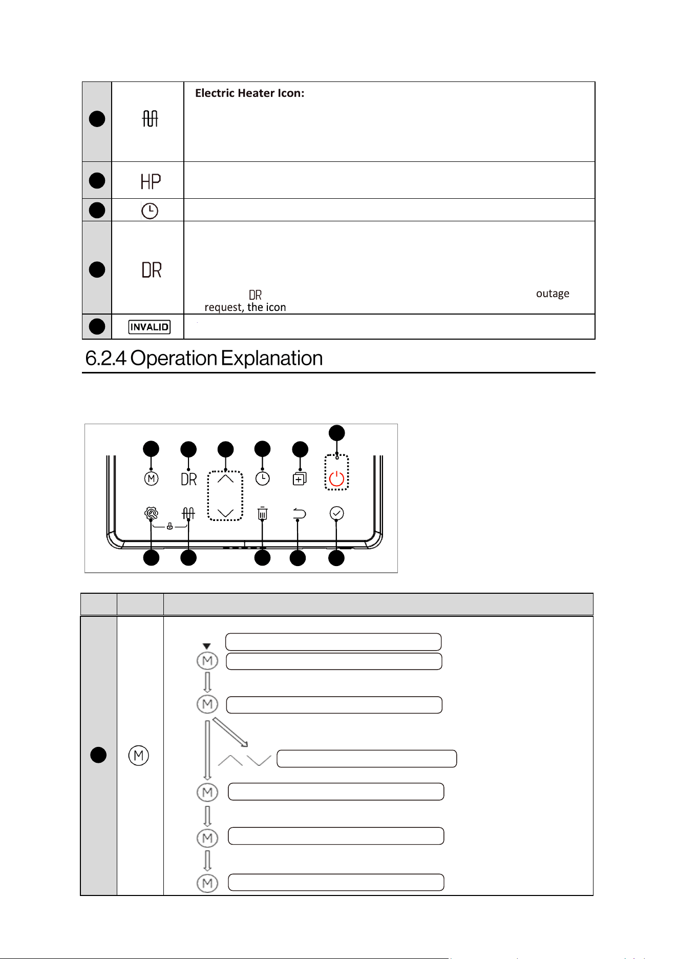
Any pressing of buon is eecve
only under buon and display in
unlocked state. (refer child lock
funcon to unlock buon/display
as shown in Table 8)
Figure 22
19
20 21
22
23
24
25 26 27
28 29
Figure 22 shows all the available buons on the controller. Refer Table 7 for detailed explanaon
of each buon. All buons are touch sensive. It is recommended not to hard press buons to
maintain the long lifespan of controller.
Table 7
No Icon Descripon
Change Mode of Operaon
Default ECONOMY mode
Switch to HEAT PUMP mode
Adjust vacaon days (1-360 days)
Switch to HYBRID mode
Switch to E-HEATER mode
Switch to ECONOMY mode
*If the mode is
changed to E-heater,
within 72 hours, it will
automacally change
back to ECONOMY
mode (when 72 hours
is the power on me)
19
Switch to VACATION mode
30
Rinnai Electric Heat Pump Water Heater Manual
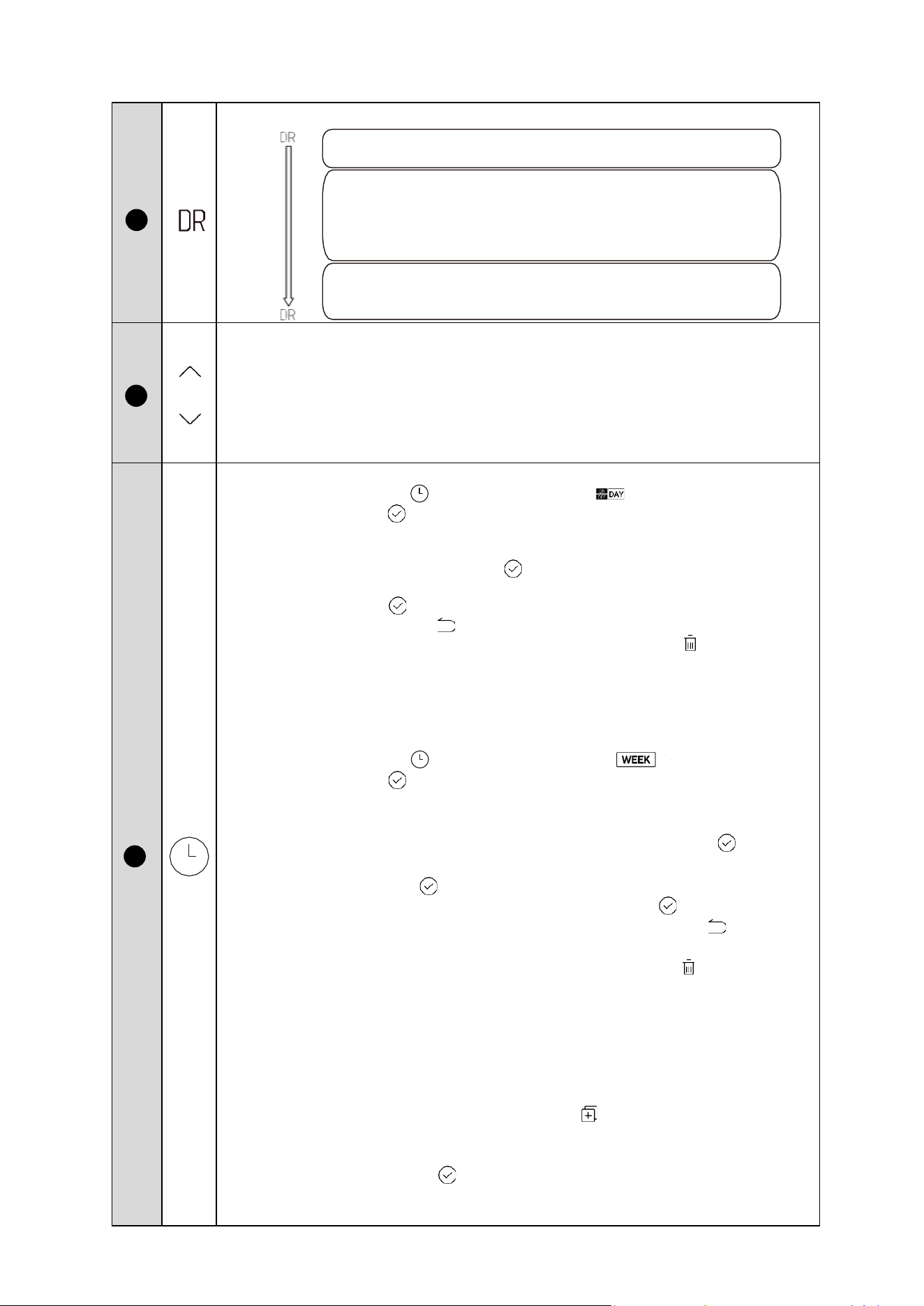
Demand Response
INCREASE AND DECREASE (UP/DOWN)
If screen is unlocked, corresponding value increases by pressing the buon.
•
When adjusng set temperature, press more than 1s, temperature value increases
connuously.
•
When seng clock/mer, press more than 1s, clock/mer value increases
connuously.
•
When seng vacaon days, press more than 1s, day value increases connuously.
DAILY SCHEDULE
1) Press the TIMER buon unl the day mer icon turns on, press the
conrmaon buon to enter the day mer seng, the day mer has a total of
6 me periods, each me period can be set to mer on, mer o, mode, set the
temperature of the water; to the rst mer period, set the temperature of the
water, press the conrmaon buon to enter the next me period of the set;
when set the sixth me period set the temperature of the water, press the
conrmaon buon to return to the main interface; during this period, you
can press the return buon Return to the previous seng
2) When seng the on me and o me, press the delete buon , the me can be
restored to the default value, and displaying ( -. --).
3) If there is a conict between the set me periods, the previous me period stays
valid, and the entered me period becomes invalid me period; the invalid me
period restores the default seng.
WEEKLY SCHEDULE
1) Press the TIMER buon unl the weekly mer icon turns on, press the
conrmaon buon to enter the weekly mer seng interface, weekly mer
is a total of 7 days, there are 6 me slots can be set each day, each me slot can
be set to mer on, mer o, the mode, set the water temperature; when the rst
me slot set the water temperature, press the conrmaon buon to enter
the next me slot sengs; when the sixth me slot set the temperature, press
the conrmaon buon to return to weekly. Aer seng the water
temperature for the 6th period, press the conrmaon key to return to the
selecon of week; during this period, you can press the return key to return to
the previous level of seng or the main interface;
2) When seng the on me and o me, press the delete buon to restore the
me, mode and set water temperature to default value, and displaying (-. --).
3) If you adjust the ming aer the seng is completed, then all the sengs aer
the adjustment me period gets canceled. For example, if you adjust the mer
on for me period 2, the mer o for me period 2, and the sengs for me
periods 3, 4, 5, and 6 get canceled to (---) aer adjustment. Mode and seng
water temperature become default values (ECONOMY, 120°F (49°C))
4) In the weekly mer seng, use the copy buon , you can locate the seng of
a certain day to the base day, select other days, press the copy buon, the fast
ashing indicates “selected” and the slow indicates “not selected”, aer pressing
on the conrmaon buon , you can copy the seng of the base day to the
selected day;
*You can enter the mer seng in both power-on and power-o state.
When the DR icon goes out, the DR funcon is not turned on.
Click this buon to turn on the DR funcon.
Aer the DR funcon is enabled, if a general power limit
request, basic load request, advanced load request, or
emergency power limit request is received, the icon will ash
slowly, when receiving an emergency power outage request,
the icon ashes quickly.
If you need to turn o the DR funcon, you need to click the
DR buon again while the DR is on and the device is on, and
the DR icon will turn o.
20
21
22

31
Rinnai Electric Heat Pump Water Heater Manual
COPY
It is used to copy selecon and paste in combinaon with other buons to
complete the funcon.
Power on/o buon
Press the buon to turn the device on or o. Small red led indicated if the device is
on/o.
Performance Data
1) In the main interface, press “ ” to enter the performance data funcon, and
use the up and down keys to switch the performance data channel, and the
aribute value of the channel will be displayed when switching to the channel.
Refer table 12 for more details.
2) Aer 30 seconds from the last operaon of the up and down keys, or by pressing
the return key or the on/o key, you can directly exit the performance data.
3) Performance data mode can be entered in both power-on and power-o state.
Engineering Mode
1) In the main interface, press and hold “ ” for 3 seconds to enter the
engineering mode; use the up and down keys to switch the engineering channel,
and the aribute value of the channel is displayed when switching to the
channel. By up and down key, you can modify a parameter seng, aer seng
and adjusng, press conrm key to return to the main interface to make the
seng eecve (channel 2, 3, 4, 34, 35 will be eecve immediately). Press the
Return buon to return to the previous interface (channel selecon interface).
Aer 30 seconds from the last operaon of the up and down buons, or by
pressing the return buon or the on/o buon, you can directly exit the
engineering mode. Refer table 10 for more details.
2) Engineering mode can be accessed in both power-on and power-o state.
NOTICE:
In order to prevent compromising the unit's regular funconing, it is strictly
forbidden for the customer to change the parameter of any/all engineering channels
without authorizaon.
E-Heater
Press the buon to turn the e-heater on instantaneously.
Delete
It is used to restore mer to default values and can be used to delete other selected
data.
Return
It is used to return to previous seng/screen.
CONFIRM/UNLOCK
If screen and buons are unlocked, press it to upload seng parameters aer
adjusng any parameter.
29
25
26
27
28
23
24
32
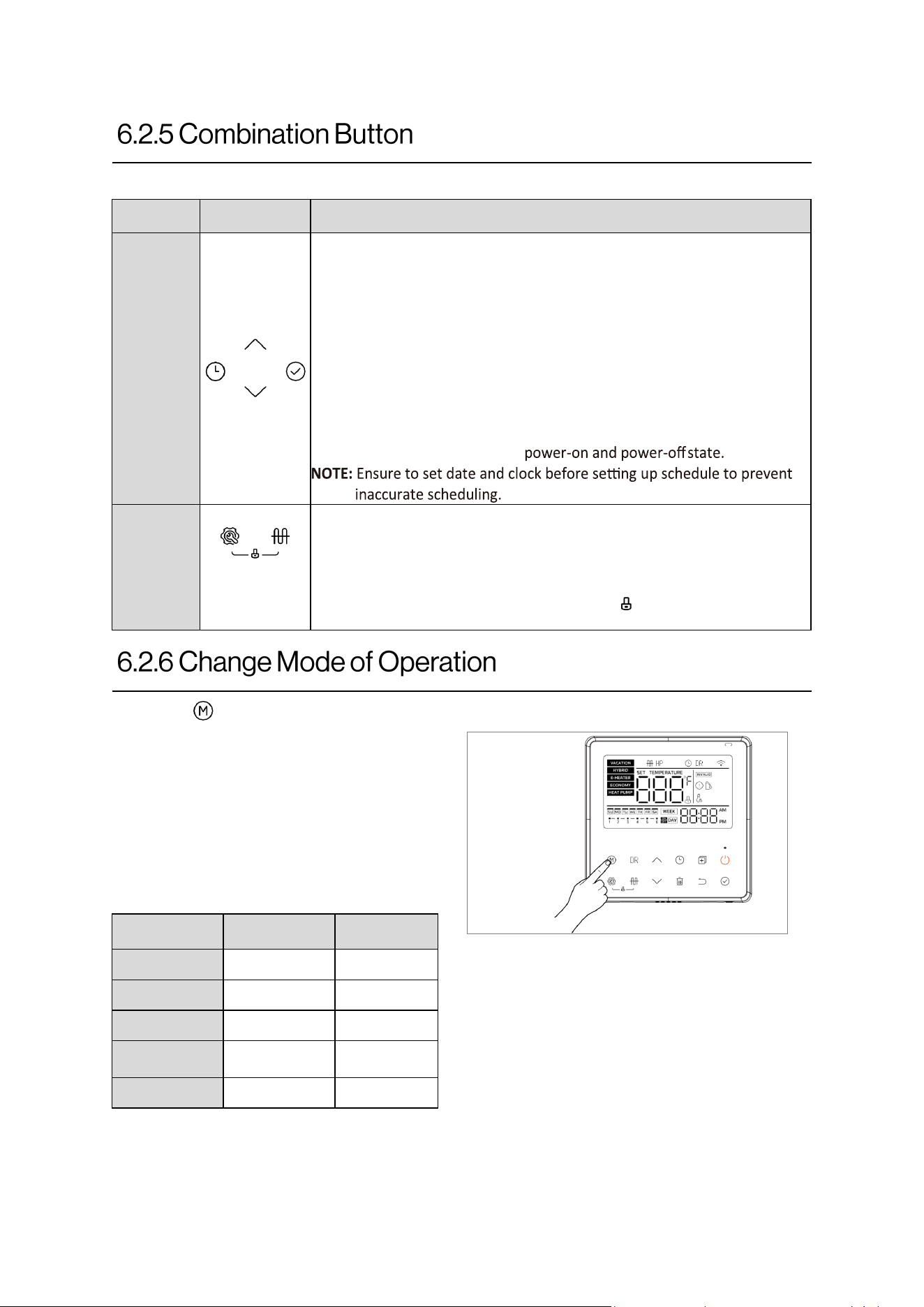
Rinnai Electric Heat Pump Water Heater Manual
No Icon
Descripon
Seng the
Date and
Clock
1) In the main interface, press and hold the mer buon for 3 seconds
to enter the date seng, press the up/down buon to select the
date, press the conrmaon buon to enter the clock seng,
press the up/down buon to modify the me, and press and hold to
accelerate the increase/de- crease of the me. Aer seng the
clock, press the conrm buon to return to the main interface to
complete the seng of date and me.
2) Aer 30 seconds from the last operaon of the up/down buon or
pressing the return buon or the power on/o buon, you can
directly exit the date and me seng;
3) Seng can be done in both
Child lock
funcon
1) In the main interface, long press the key combinaon for 2 seconds
to enter the child lock state;
2) In the state of child lock, long press the key combinaon again for 2
seconds to release the child lock state;
3) In the locked state, there will be an icon next to the water
temperature display.
Press for
2 sec
+ +
Table 8
Table 9
Mode Eciency Recovery
Vacaon
N/A N/A
Hybrid
Low High
E-Heater
Very Low Very High
Economy
(Default)
High Low
Heat-Pump
Very High Very Low
Figure 22
Press the “ ” buon to change operang mode on the unit (refer Figure 22).
Operaon Modes:
• ECONOMY (Default)
• HEAT-PUMP
• VACATION
• HYBRID
• E-HEATER
33
Rinnai Electric Heat Pump Water Heater Manual
Table 10
Engineering
Channel 1
Unit Temperature
0: °F (Default)
1: °C
Engineering
Channel 2
Maintenance Reminder
0:o
1:on (Default)
Engineering
Channel 3
Maintenance Time Seng
Default value: 365 days
(It can be set between 30 ~365 days)
Engineering
Channel 4
Maintenance Time Reset
0:Do not clear (Default)
1:Clean up (Resets the maintenance me to preset
days) (clears the icon from display)
Engineering
Channel 5
Clear Error Code
0: Default
1: Clear Error Code (Mainly used to clear error code
PhdH)
NOTE: DO NOT clear error without taking prevenve
acons rst.
Engineering
Channel 6
Electric Heater Switch
0: O (Permanently turns o electric heater)
1: On (Default)
Engineering
Channel 7
Automac Self Cleaning
Switch
0: O (Default) (Permanently turns o automac
self cleaning funcon)
1: On
Engineering
Channel 9
Set Self Cleaning Hours
Default value: 10 hours
(It can be set between 0~23 hours)
Engineering
Channel 11
Set Vacaon Temperature
Default value: 15°C
(It can be set between 15~20° C)
Engineering
Channel 14
N/A
Default value:
COO
NOTICE: DO NOT change the default seng.
Engineering
Channel 15
Dry Fire Protecon Switch
0: Invalid (Permanently turns o dry re protecon
funcon)
1: Valid (default)
NOTICE: DO NOT change the default seng unless
used for troubleshoong.
Engineering
Channel 16
Current Detecon Switch
0: Invalid (Permanently turns o current detecon
funcon)
1: Valid (default)
NOTICE: DO NOT change the default seng unless
used for troubleshoong.
3 Seconds
Figure 23
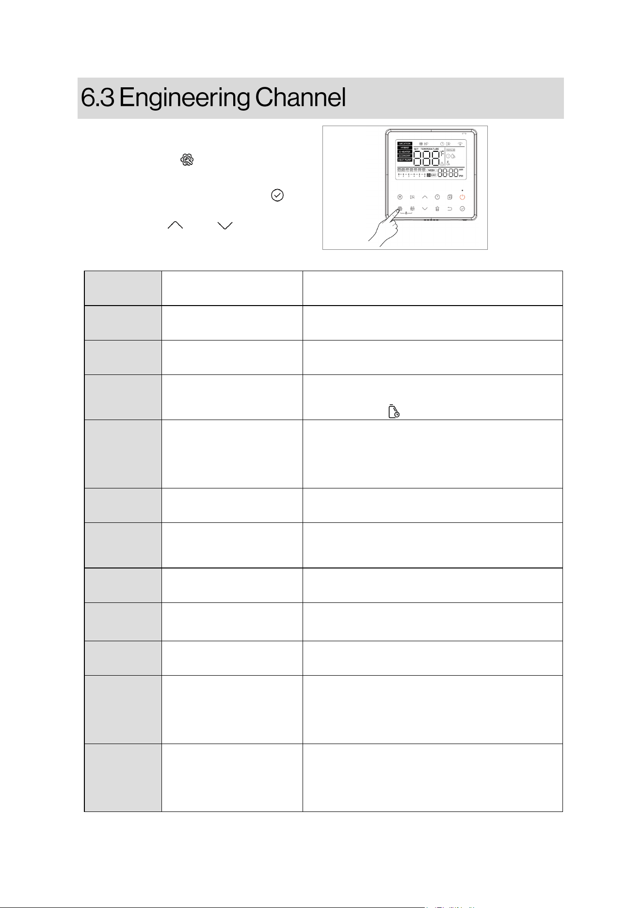
To enter the engineering channel mode:
Press and hold the “ ” buon for 3 seconds
on the main interface.
Select engineering channel, press the “ ”
buon to enter, and switch between valid
values using the “ ” and “ ” buons
(Refer Figure 23).
34
Rinnai Electric Heat Pump Water Heater Manual
Engineering
Channel 17
Set Self Cleaning
Temperature
Default value: 65°C
(It can be set between 65 ~ 70°C)
Engineering
Channel 18
Higher Set Temperature
Default value: 65°C
(It can be set between 65 ~ 70°C)
Engineering
Channel 21
Set 485 Communicaon
Address
Default value: 1
(It can be set between 1 ~ 20)
Engineering
Channel 23
Reset All Channels
0:o (Default)
1:on (Valid only once) (resets all engineering
channels to default)
Engineering
Channel 26
Set Self Cleaning Minutes
Default value: 0 minutes
(It can be set between 0~59 minutes)
Engineering
Channel 27
N/A
Default value:
1
NOTICE: DO NOT change the default seng.
Engineering
Channel 30
Backlight
0:o (Backlight stays always on)
1:on (Backlight turn on only when buon pressed)
(Default)
Engineering
Channel 34
Alarm Sound Disable
0:o (Default) (beeps when audible error code
occurs)
1:on (turns o audible sound of error code)
NOTICE: ALWAYS set channel back to default aer
taking correcve acons.
Engineering
Channel 35
Automac Child Lock
0:o (Default)
1:on (Locks buon aer 1 minute of no use)
Engineering
Channel 38
Shut-O Valve Seng
0:o (Default)
1:on
NOTICE: Must set to “ON” when leak kit
(103000119) is installed.
Engineering
Channel 39
Self Cleaning
0:o (Default)
1:on (Valid only once) (heats up tank water to 150°F
(65°C))
Engineering
Channel 40
Duct Seng
0:o (No Duct installed) (default)
1:on (Duct installed)
NOTICE: Must set to “ON” when duct kit
(103000120) is installed.
35
Rinnai Electric Heat Pump Water Heater Manual
To avoid scalding risks, ensure that no one
is exposed to hot water when manually
operang the relief valve. Release the water
into an appropriate drain to avoid injuries
or property damage.
DANGER
Thermal expansion in a closed loop water
system can cause the temperature and
pressure relief valve on the water heater to
discharge periodically.
Consult your water heater supplier or a
qualied plumber to correct it. DO NOT
block the relief valve outlet.
NOTICE
Regular maintenance ensures your water
heater's long, trouble-free operaon. This ap-
pliance has a maintenance reminder. Default is
365 days. When the maintenance me is due,
display shows icon. Establish and follow a
maintenance roune. Refer table 10 to reset
maintenance mer once compleng all check-
ups/clean ups.
Note that most electrical appliances, including
new ones, produce some operaonal noise. If
you noce an excessive increase in noise levels,
contact a qualied installer or plumbing
contractor for inspecon.
When water-using appliances with solenoid
valves close rapidly, it may cause a hammering
eect / noise in the water pipes. To minimize
this issue, you can use strategically placed ris-
ers in the water pipe system or employ water
hammer arresng devices.
IMPORTANT: Li and release the lever handle
on the T&P valve, located on the side of the
water heater, at least once a year to conrm its
Turn o the water heater's power before
beginning to drain water.
CAUTION
Ensure safety by conrming that nobody is
in the vicinity of the hot water discharge
when using the drain valve. The water from
the tank could cause scalding, so direct it to
a proper drain to prevent harm or damage.
DANGER
Sediments suspended in water can
accumulate at the boom of a water heater's
tank, oen due to hard water. To prevent
this buildup, it's recommended to drain a few
quarts of water from the tank every month.
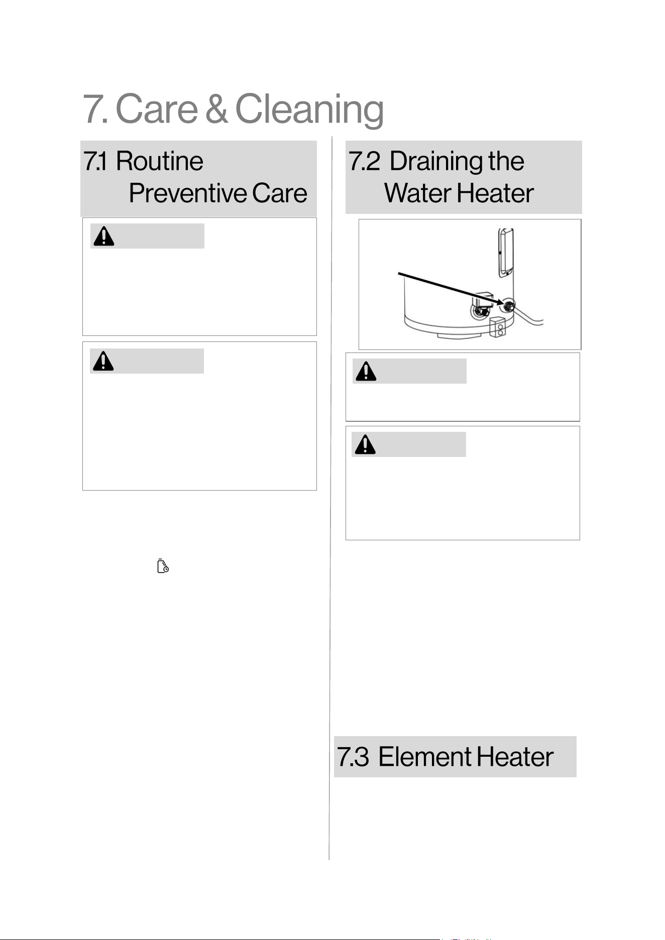
To drain the water heater, rst shut-o the
cold-water supply. Then, either open a hot
water faucet or li the relief valve easing
gear to let air into the tank. You must rst
aach the garden hose. Then close cold
supply, and open hot faucet/T&P valve, then
open drain valve.
Figure 24
Drain
Valve
Check if the resistance across element heater
is 15 Ohms ± 10 Ohms. If resistance is out of
range, replace the element heater. Refer table
14 to order element heater replacement part.
36
Rinnai Electric Heat Pump Water Heater Manual
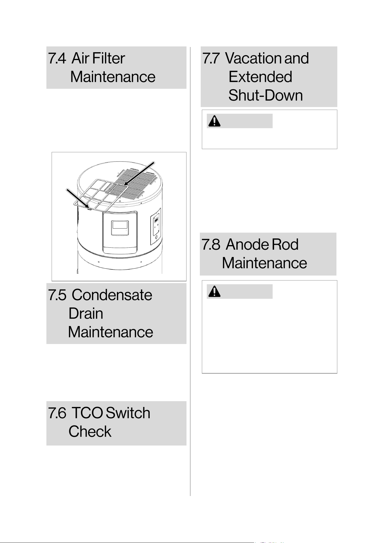
It's recommended to clean the air lter
located on the top of the water heater
every 3 months. Clean it with mild
detergent and water, then dry and install it
back. To remove the lter, li and slide it to
the front of the unit, and to replace it,
lower it into the lter slot on top
Refer to the Hydrogen Gas Cauon in the
Operang Instrucons.
NOTICE
Change the mode of operaon to “VACATION”
if water heater not in use for a long me, to
save energy and avoid hydrogen gas build-up.
In case of unit shut down, drain the water
heater and pipes to prevent damage from
freezing. Have a professional inspect the
heater aer a long shutdown and ensure its
fully relled before use.
Avoid removing the anode rod from the
water heater as it shortens the tank's
lifespan and voids the warranty. The anode
rod is designed to reduce corrosion in the
glass-lined tank and is slowly consumed.
High sulfate/mineral content in water can
cause a roen egg smell and chlorinaon of
the water supply can reduce this.
NOTICE
This water heater is equipped with an anode
rod engineered to extend the longevity of the
glass-lined tank. The anode rod undergoes
gradual consumpon, eecvely prevenng
or reducing corrosion of the glass-lined tank.
It is recommended to replace anode rod
every 5 years (IMPORTANT: life of the
anode rod depends on the water usage and
quality. It may need to be replaced earlier
than recommended me).
Filter
Handle
Horizontal
Air Filter
Figure 25
Ensure unobstructed condensate ow, clear
blockages if necessary. Pour a cup of bleach
into the condensate drain access opening at
least once a year to eliminate any algae, mold,
or mildew that may have developed in the
pipe.
Perform a connuity test between all 4
mounng screws around TCO switch to ensure
TCO switch works ne. If it fails connuity test,
replace the TCO switch. Refer table 14 to order
TCO replacement part.
37
Rinnai Electric Heat Pump Water Heater Manual
Save me and money! Review the
chart on this page rst and you
may not need to call for service.
Q: Why can’t compressor start immediately
aer seng?
A: The unit will wait for 3 min to balance the
pressure of system before starng the
compressor again, it's a self-protecon
logic of unit.
Q: Why does the temperature shown on the
display panel decreased while unit is
running?
A: When the upper tank temperature is much
higher than the lower tank temperature,
the upper hot water will be mixed by the
lower cold water which connually ows
from inlet. This will decrease the upper
temperature.
Q: Why does the element heater never turns
on even if tank temperature is signicantly
lower than set temperature?
A: Scenario 1: The unit is able to fulll hot
water demand without ulizing the backup
element heater.
Scenario 2: If unit is turned on for the rst
me, it goes through inial set up and runs
the dry-re protecon logic to ensure that
the tank is lled with water.
Scenario 3: Check if electric heang switch
parameter is set correctly. Engineering
channel 6 should be set to “
1
”.
Q: Why does the temperature display show
low temperature when hot water is sll
available?
A: the upper temperature sensor is located
1/4 from the top of the tank. It is possible
for the top 1/4 to sll be hot.
Q: Why are the buons unavailable
somemes?
A. The unit features child lock funcon to
avoid any accidental touch. It is indicated
by “ ” icon on the display. To unlock,
press “ ” and “ ” simultaneously for 2
seconds.
1. If an error occurs and unit starts again
aer self diagnoscs/restart, please
contact qualied and trained
professional for maintenance.
2. If an error occurs and unit does not start,
please cut o the power supply and
contact qualied and trained
professional for service. DO NOT aempt
to resolve the error in the absence of
qualied professional.
3. If a fault occurs, the “
” icon will light
up, the buzzer will beep at intervals, and
the main interface will display a fault
code.
4. Refer Secon 8.4 (Table 13) for more
details.
38
Rinnai Electric Heat Pump Water Heater Manual
Data Name Performance Data Descripon Unit
Upper water temperature sensor (T5U)
°F/°C
Lower water temperature sensor (T5L) °F/°C
N/A (Default: ---) -
Heat pump operang temperature max. °F/°C
Evaporator temperature sensor (T3) °F/°C
Ambient temperature sensor (T4) °F/°C
Compressor discharge temperature sensor (TP)
°F/°C
Compressor sucon temperature sensor (TH) °F/°C
N/A (Default: ---) -
N/A (Default: ---) -
Set temperature for self cleaning
°F/°C
Compressor and electric heang current Amps
DC fan Speed (rpm/10)
Machine Parameters (
0
~
255
) -
Electronic expansion valve opening Angle (Degree)
Compression mechanism hot water demand -
N/A (Default: ---) -
N/A (Default: ---) -
Fan Type (
0
: AC fan or
1
: DC fan) -
Electric heater controller type -
Compressor controller type -
N/A (Default: ---) -
Tank capacity Liters
N/A (Default: ---) -
N/A (Default: 0) -
Main PCB soware version -
Display controller soware version -
N/A (Default: 000) -
No of Electric heaters (
0
: one e-heater or
1
: two e-heaters) -
N/A (Default: 2) -
Last error code Error Code
2
nd
last error code
Error Code
3
rd
last error code
Error Code
Maintenance me days
Set (target) Temperature
°F/°C
End of the performance list -
Table 12
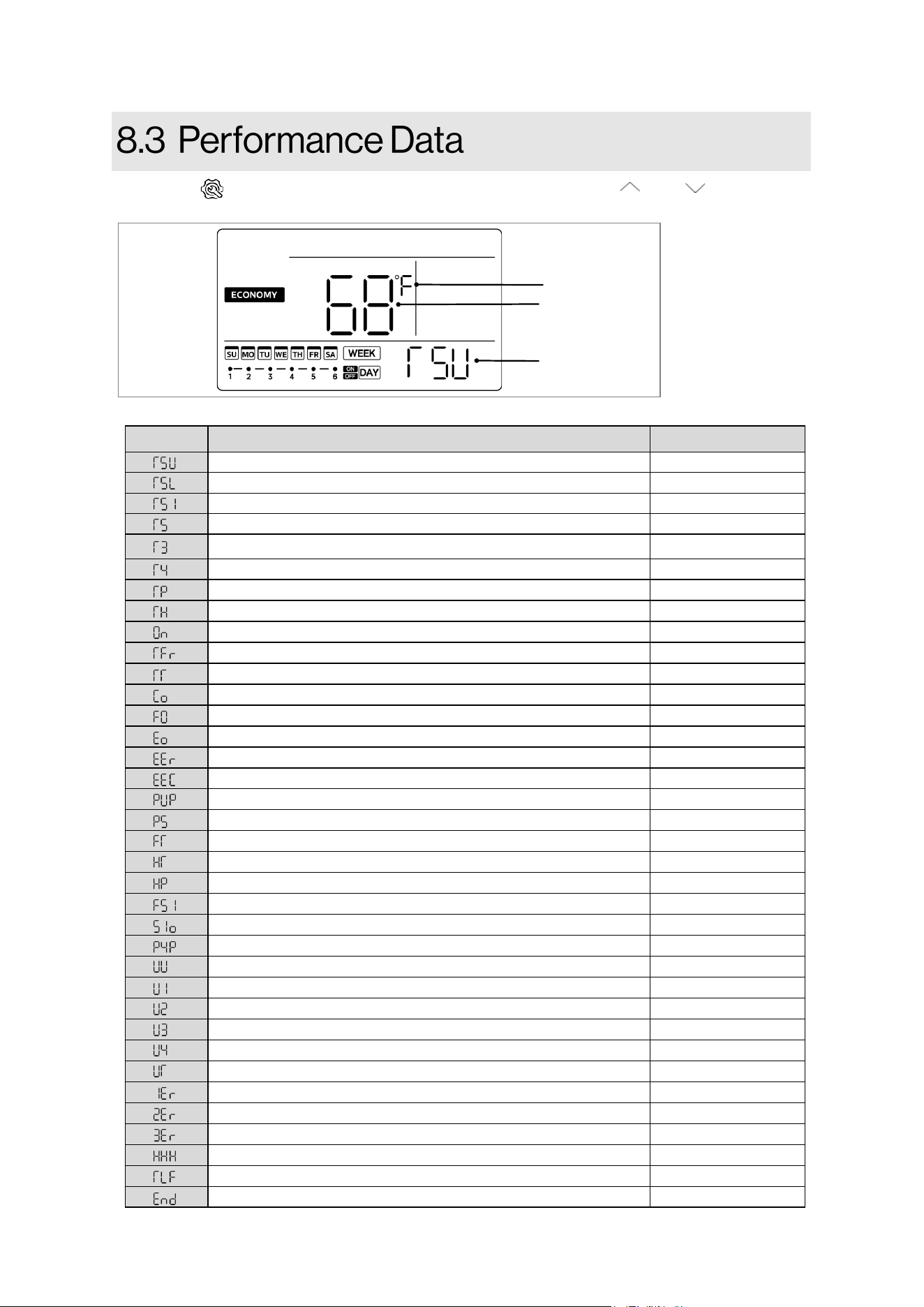
Data Name
Figure 26
Performance Data
Unit (If applies)
Press the “ ” buon (for <3 sec) to see the performance data. Use “ ” or “ ” buons
to scroll through each performance data. Refer Table 12 for data descripon and unit.
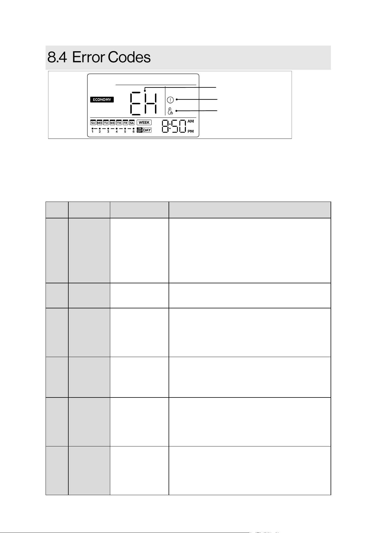
39
Rinnai Electric Heat Pump Water Heater Manual
Display
Unit Status
Malfuncon
Descripon
Correcve acon
EH0b
Unit Lockout
Controller to PCB
communicaon
error (controller
stops working/
malfuncon)
1. Power cycle the unit.
2. Turn o electrical power at breaker.
3. Disconnect and reconnect controller cable to
controller.
4. Disconnect and reconnect CN53 connector on the
main PCB.
5. If the error persists, contact a qualied person to
replace controller.
EH00
Unit Lockout
Machine working
parameters are
abnormal.
1.
Power cycle the unit.
2. If the error persists, contact a qualied person to
replace main PCB.
EH03
Unit Lockout
Fan motor fault
1. Turn o electrical power at breaker.
2. Disconnect and reconnect CN51 connector on the
main PCB.
3. Inspect fan motor wire for damage.
4. If the error persists, contact a qualied person to
replace fan motor.
PH15
Unit Lockout
Electric current
leakage (If PCB
current dierence
between L,N
>14mA)
1. Power cycle the unit.
2. Turn o electrical power at breaker.
3. Check all connecons on the main PCB.
4. If the error persists, contact a qualied person to
replace main PCB.
EC54
Unit Lockout
Compressor
discharge
temperature
sensor (TP) failure.
1. Turn o electrical power at breaker.
2. Disconnect and reconnect CN28 connector on the
main PCB.
3. Inspect wire for damage.
4. If the error persists, contact a qualied person to
replace temperature sensor.
EH5H
If both T3 and
TH fail, ONLY
heat pump
stops
Compressor
sucon
temperature
sensor (TH) failure.
1. Turn o electrical power at breaker.
2. Disconnect and reconnect CN29 connector on the
main PCB.
3. Inspect wire for damage.
4. If the error persists, contact a qualied person to
replace temperature sensor.
Table 13
• Refer the following table to understand the occurring error code and take correcve acons
accordingly. If there is any acve error code, error code icon lights up and unit beeps unl
the error code is resolved or turned o manually.
• All alarms are audible (makes beeping noise) and they can be turned o by changing the
engineering channel 34 to “ 1 ”.
NOTICE: ALWAYS set engineering channel 34 back to “ 0 “ once the error code is resolved.
Figure 27
Error code icon
High Temp. Alert (if applies)
Error code
40
Rinnai Electric Heat Pump Water Heater Manual
EC53
If both T4
and T3 fail,
ONLY heat
pump stops
Ambient
temperature sensor
(T4) failure.
1. Turn o electrical power at breaker.
2. Disconnect and reconnect CN28 connector on the
main PCB.
3. Inspect wire for damage.
4. If the error persists, contact a qualied person to
replace HP temperature sensor
EC52
If both T4
and T3 fail,
ONLY heat
pump stops
Evaporator
temperature sensor
(T3) failure.
1. Turn o electrical power at breaker.
2. Disconnect and reconnect CN28 connector on the
main PCB.
3. Inspect wire for damage.
4. If the error persists, contact a qualied person to
replace HP temperature sensor
EH5L
If both T4
and T3 fail,
Unit lockout
Lower tank water
temperature sensor
(T5L) failure.
1. Turn o electrical power at breaker.
2. Disconnect and reconnect CN24 connector on the
main PCB.
3. Inspect wire for damage.
4. If the error persists, contact a qualied person to
replace water temperature sensor
EH5U
If both T4
and T3 fail,
Unit lockout
Upper tank water
temperature sensor
(T5U) failure.
1. Turn o electrical power at breaker.
2. Disconnect and reconnect CN24 connector on the
main PCB.
3. Inspect wire for damage.
4. If the error persists, contact a qualied person to
replace water temperature sensor
EH5d
ONLY
E-Heater
Stops
Electric heater open-
circuit error
1. Turn o electrical power at the breaker.
2. Check if TCO switch is triggered. If triggered, follow
secon 9.4 to reset it.
3. Check wires at elements, thermostat and control
assembly board for damage.
4. If the error persists, contact a qualied person.
EHHP
ONLY Heat
Pump Stops
Heat pump system
fault.
(When PH20,
PH21, PC30, PC06
any protecon
appears 3 mes or
the protecon lasts
more than 1 hour)
Call our Technical Support Team on a toll free number
which is listed in secon 9.6, “How to Obtain Service”.
PhdH
Unit
Lockout
Dry Fire protecon.
1. Turn o electrical power at breaker.
2. Check if tank is fully lled with water. If not, add
water by opening a hot water faucet to bleed all air
unl water ows without air bursts.
3. Turn on electrical power at breaker.
PH20
ONLY Heat
Pump Stops
Compressor
discharge
temperature
protecon (too low)
Call our Technical Support Team on a toll free number
which is listed in secon 9.6, “How to Obtain Service”.
PH21
ONLY Heat
Pump Stops
Compressor working
current protecon
(too high)
1. Power cycle the unit to see if code clears.
2. Turn o electrical power at breaker.
3. Inspect wire for damage.
4. If the error persists, contact a qualies person to
replace temperature sensor.

41
Rinnai Electric Heat Pump Water Heater Manual
PH24
Shut-o
valve closes
Freeze protecon
(When T5L< 39°F(4°
C) and T4 < 45°F(7ºC)
1. Power cycle the unit to see if code clears.
2. If error persists, call our Technical Assistance
Hotline which is listed on the water heater’s
warranty sheet for further assistance.
PC30
ONLY Heat
Pump Stops
S
ystem high pressure
protecon
(protecon acve
when ≥3.0MPa acve
and inacve when ≤
2.4Mpa)
1. Check if the air lter or air outlet is blocked. If
blocked, clean and see if the error code clears.
2. Check if evaporator is covered with too much dust.
3. If the error persists, contact a qualied person to
service the unit.
PC06
ONLY Heat
Pump Stops
High TP protecon.
(protecon acve
when TP > 221°F
(105°C) and inacve
when TP < 194°F (90°
C).
1. Turn o electrical power at breaker.
2. Disconnect and reconnect CN28 connector on the
main PCB.
3. Inspect wire for damage.
4. If the error persists, contact a qualied person to
service the unit.
PH9b
Unit
Lockout
Overtemperature
protecon. (When
the water
temperature exceeds
the set temperature
by more than 9°F (5°
C)).
1. Turn o electrical power at breaker.
2. Disconnect and reconnect CN24 connector on the
main PCB.
3. Inspect wire for damage.
4. If the error persists, contact a qualied person to
service the unit.
PH91
ONLY Heat
Pump Stops
Low T3 protecon.
1. Turn o electrical power at breaker.
2. Disconnect and reconnect CN28 connector on the
main PCB.
3. Inspect wire for damage.
4. If the error persists, contact a qualied person to
service the unit.
PH22
Shut-o
valve closes
Tank leakage
protecon
1. Turn o electrical power at the breaker, check all
electrical connecons, and wiring for damage.
2. Check for plumbing leaks and correct accordingly.
3. If tank is leaking, call our Technical Support Team
on toll free number which is listed on the water
heater’s warranty sheet for further assistance.
PHL1
ONLY Heat
Pump Stops
Condensate drain
leakage protecon
1. Check if the condensate line is clogged. If clogged,
follow instrucons of secon 7.5 to clean it.
2. Check if the water level switch located near
compressor works.
3. Disconnect and reconnect CN10 connector on the
main PCB.
4. If error persists, contact a qualied person service
the unit.
FC06
Shut-o
Valve closes
Shut-o valve
malfuncon
1.
Check if the shut-o valve connector is connected.
2.
Ensure that the shut-o valve motor assembly is
properly secured to valve.
3.
If it does not work properly, contact a qualied
person.
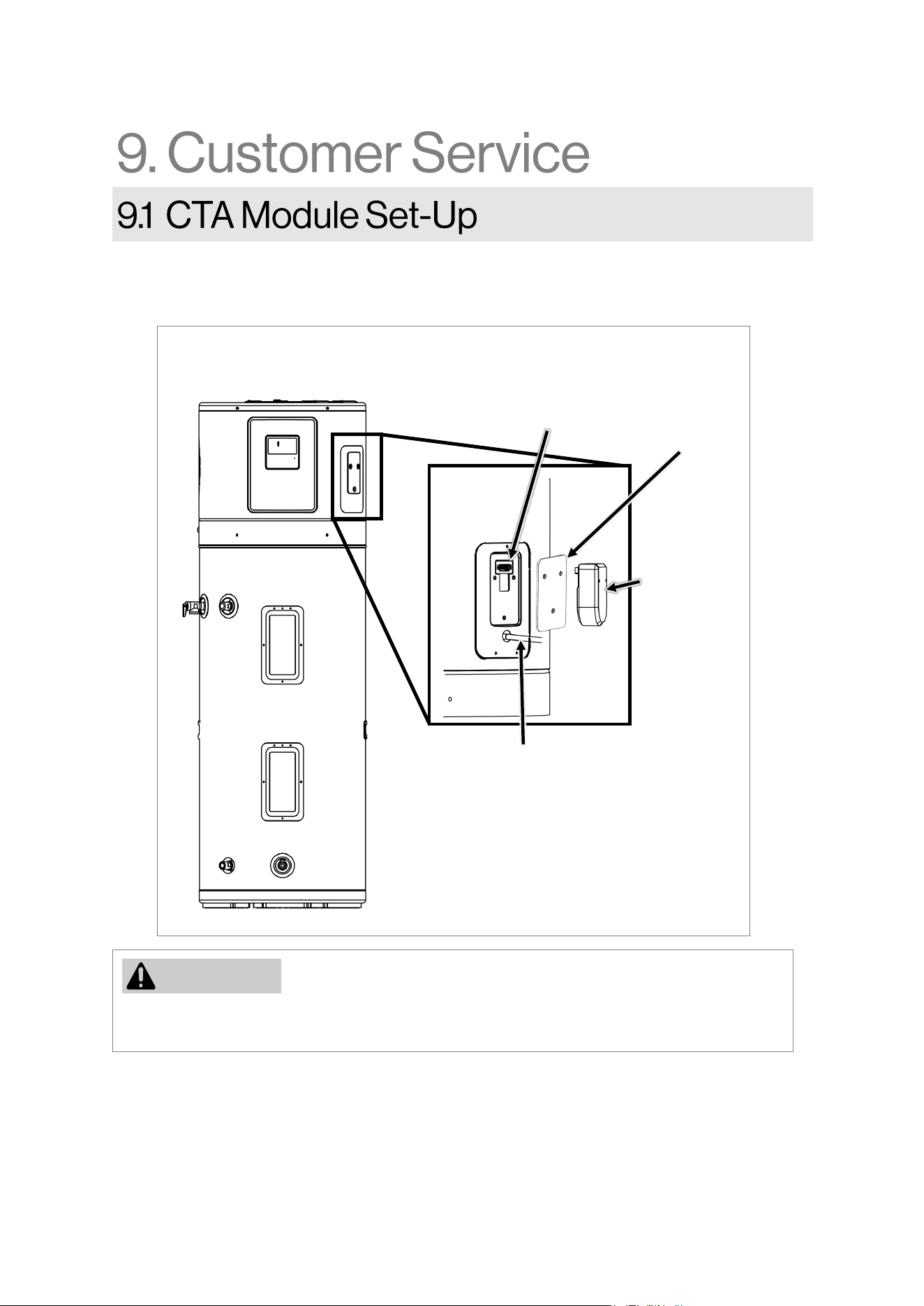
42
Rinnai Electric Heat Pump Water Heater Manual
CTA-2045
Module
(Not supplied)
Conduit
Connector
CTA Module Connecon Port
A CTA2045 compliant Module can be connected to the water heater’s connecon port. Follow
the instrucons from the CTA2045 Module supplier for inial startup.
NOTICE
Figure 28
CTA Module
Connecon Port
Juncon Box
Cover (CTA 2045)
As shown in Figure 28, CTA module connecon port is located on top right side of water
heater. To gain access of the port, remove 3 screws holding juncon box cover and connect the
module to the port.
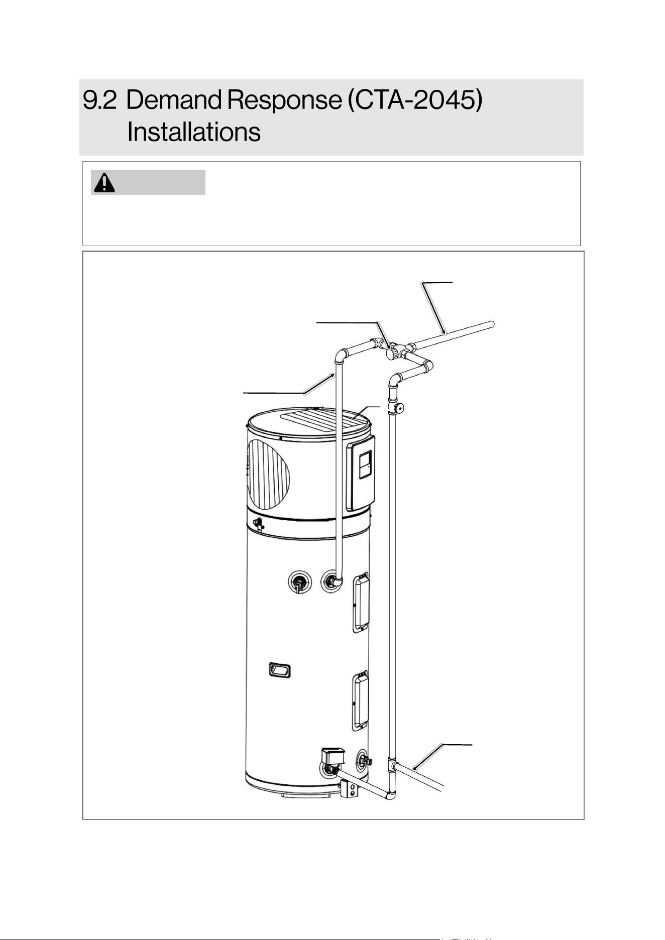
43
Rinnai Electric Heat Pump Water Heater Manual
Hot Water Outlet
3/4” Tempered
Domesc hot water
Supply to house
Nominal 3/4” size mixing or
tempering valve (refer to warning
above). Follow mixing or tempering
valve manufacturer's instrucons for
installaon of the valve
Cold Water Outlet
In demand response applicaons, a thermostac mixing valve in compliance with ASSE 1017
must be placed on the hot water supply line, following all installaon instrucons provided by
the manufacturer.
NOTICE
Figure 28
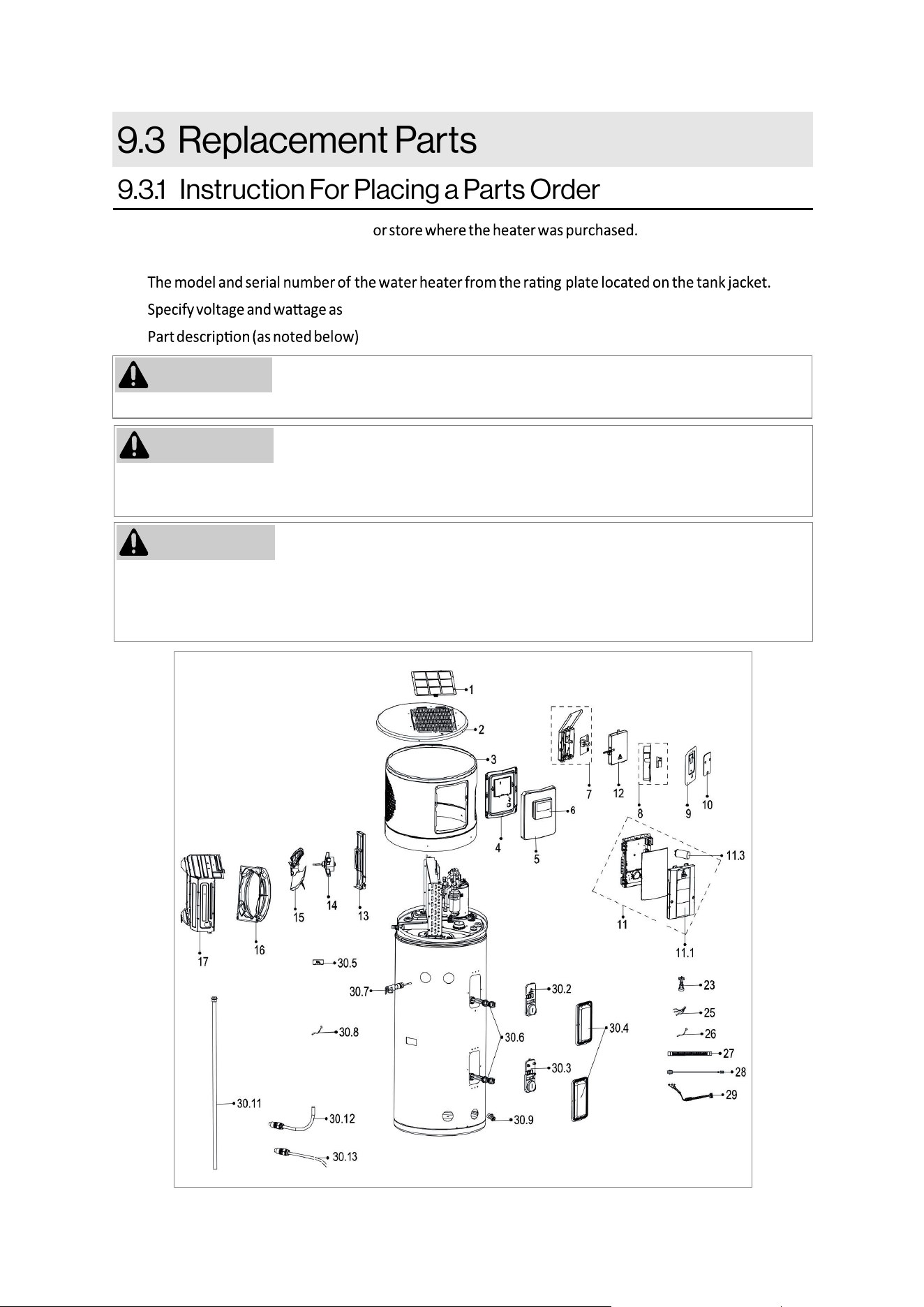
44
Rinnai Electric Heat Pump Water Heater Manual
For your safety DO NOT aempt repair of electrical wiring, heang elements, heat pump or electronic
controls. Refer repairs to qualied service personnel
Address parts orders to the distributor
All parts orders should
include:
1)
2)
marked on the rang plate.
3)
and number of parts desired.
CAUTION
FLAMMABLE CONTENTS UNDER PRESSURE. The compressor is not a serviceable part. The
compressor wiring terminals may are allowing pressurized refrigerant and oil to escape, ignite and
cause serious bodily injury, severe burns or death.
WARNING
Check the water heater’s rating label on the front of the unit for the acceptable element wattage.
NOTICE
Figure 29
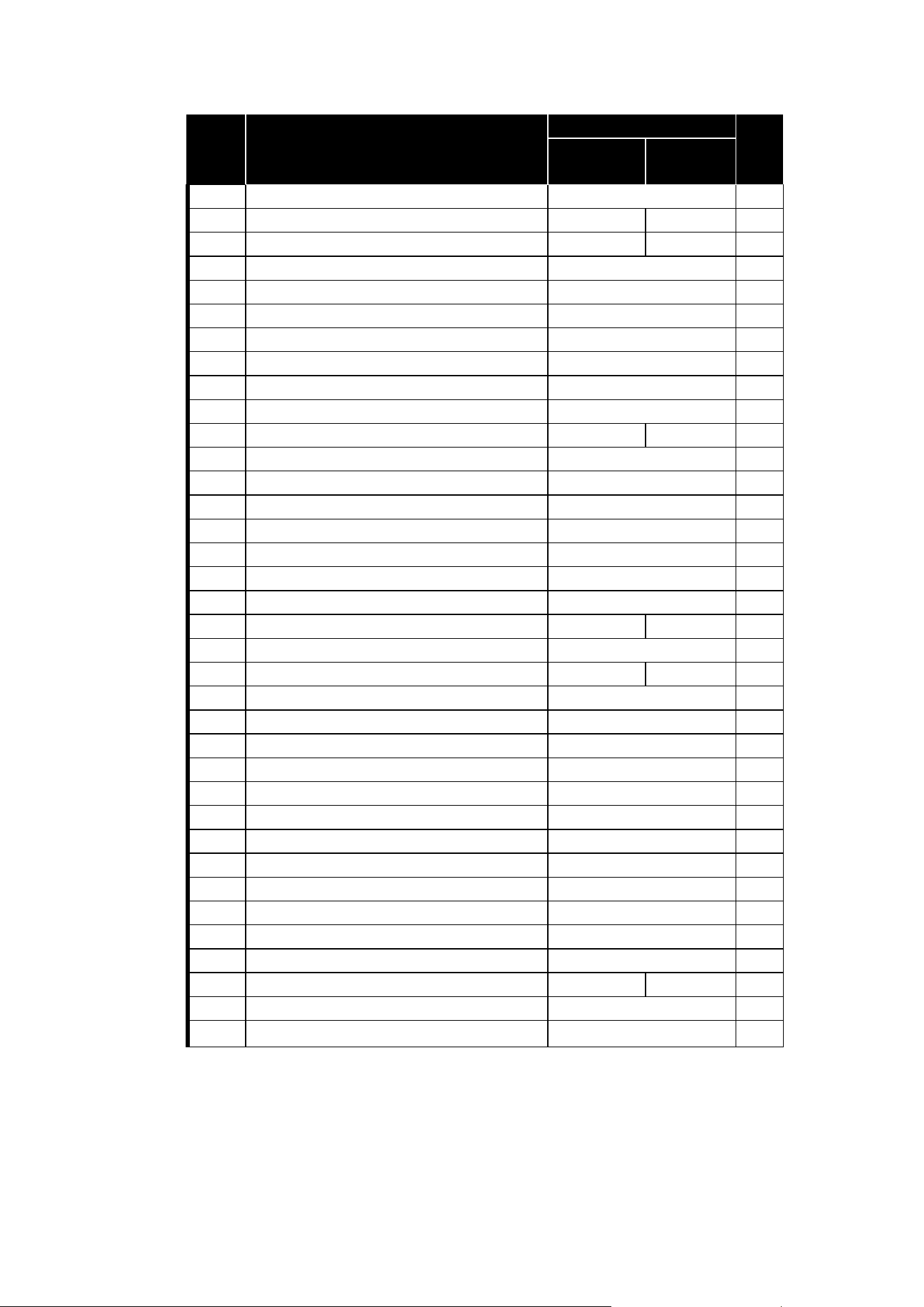
45
Rinnai Electric Heat Pump Water Heater Manual
Item Descripon
Part Number
Qty
50 Gallon 80 Gallon
1
Air Filter 108000136 1
2
Top Cover 109001486 109001489 1
3 Front Cover 109001485 109001488 1
4 Display Box Rear Cover 109001483 1
5 Display Box Front Cover 109001478 1
6 Display Box Assembly 105002062 1
7 Relay Board E-Box Assembly 105002060 1
8 Juncon Box Subassembly 105002061 1
9 Juncon Box Cover 109001477 1
10 Juncon Box Cover (CTA-2045) 109001479 1
11 Main Control E-Box Assembly 105002065 105002068 1
11.1 Main Control E-Box Lid Assembly 109001480 1
11.3 Compressor Capacitor 105002063 1
12 Cover of Relay Board E-Box 109001482 1
13 Motor Holder Assembly 109001481 1
14 Fan Motor 108000140 1
15 Axial Flow Fan 108000137 1
16 Venlaon Ring 108000141 1
17 Fan Box Assembly 108000138 108000139 1
23 Water Level Switch 105002058 1
25 HP Temperature Sensors (T3, T4, TP) 105002066 105002067 1
26 Sucon Line Temperature Sensor (TH) 105002059 1
27 Drainage Pipe 107000674 1
28 Ground Wire 105002055 1
29 Compressor Harness 105002056 1
30.2 Insulang Cover (Upper) 109001492 1
30.3 Insulaon Cover (lower) 109001493 1
30.4 Cover (TCO)/Cover (Electric Heater) 109001491 2
30.5 Thermal Cut-o (TCO) 105002070 1
30.6 Element Heater 105002064 1
30.7 T&P Valve 107000677 1
30.8 Water Temperature Sensor 105002069 2
30.9 Drain Valve 107000678 1
30.11 Anode Rod 107000679 107000680 1
30.12 Water Outlet J-Tube 107000675 1
30.13 Water Inlet Pipe Assembly 107000676 1
Table 14
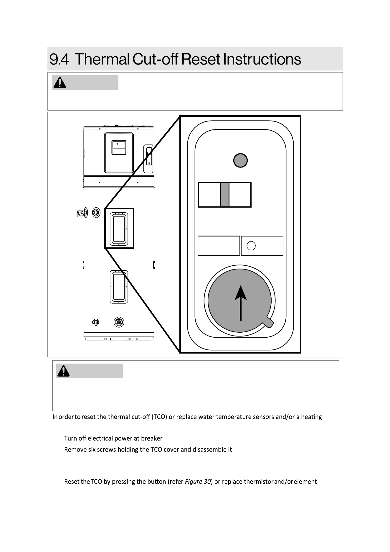
46
Rinnai Electric Heat Pump Water Heater Manual
The following instrucons are intended for qualied service personnel ONLY and should only be
done when necessary.
CAUTION
Press the buon to reset
Figure 30
element, follow the instrucons below:
1.
.
2.
.
3. Remove one screw holding insulang cover to gain access to TCO/ water temperature
sensor/heang element.
4.
as
necessary.
5. Remount the insulaon cover, TCO cover, and turn on the electrical power at breaker.
Before working near an energized circuit, ensure that all power to the unit is disconnected.
Neglecng to do so may lead to electrical shock, causing signicant personal injury or even
death.
WARNING
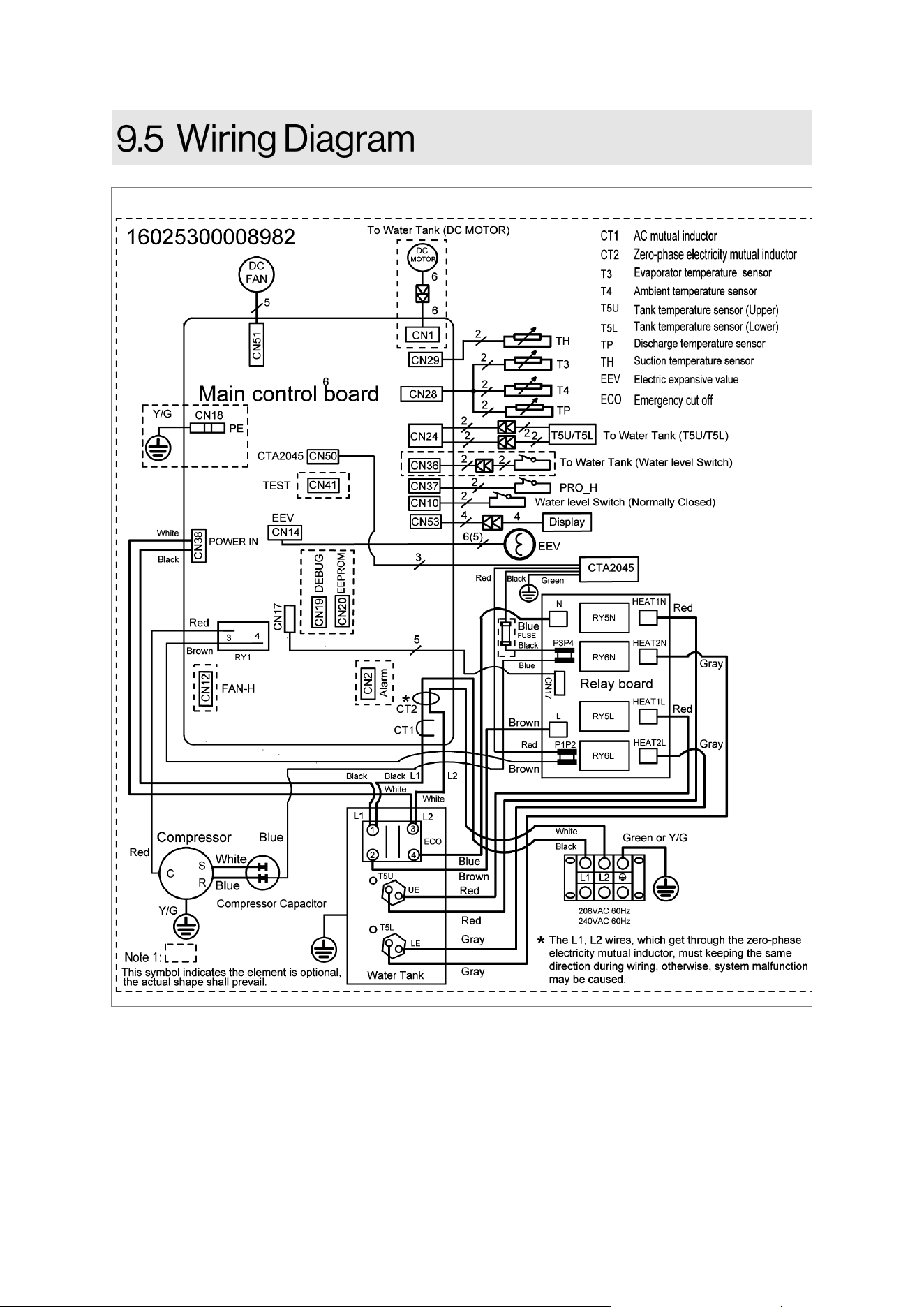
47
Rinnai Electric Heat Pump Water Heater Manual
Figure 31
48
Rinnai Electric Heat Pump Water Heater Manual
What Is Covered?
The Rinnai Standard Limited Warranty covers any defects in materials or workmanship when the
product is installed and operated according to Rinnai published product specicaons, subject to
the terms within this Limited Warranty document. This Limited Warranty applies only to products
that meet the requirements of a “qualied product installaon” and are originally installed in the
United States and Canada. Improper installaon may void this Limited Warranty. A “qualied
product installaon” consists of the following: (1) installed by a company or individual which holds a
current government issued license which ceres the company or individual is qualied to install
and service Electric Heat Pump Water Heater in the state where the product is located, if such
licensing is required; and (2) installaon, startup, operaon and service is performed in compliance
with (a) all Rinnai published engineering, applicaon, installaon, startup and service
documentaon, (b) all applicable federal, state and local laws, (c) applicable plumbing, electrical,
mechanical and building codes and best industry standards. This Limited Warranty is subject to the
condions that the Rinnai electric heat pump water heater has been installed per the “qualied
product installaon” terms and ongoing and proper maintenance has been performed, according to
Rinnai Installaon and Service documentaon, by a professional, licensed (if required) contractor.
Proof of the required service and maintenance tasks being completed must be kept in the provided
Rinnai Installaon and Service Record. This Limited Warranty coverage, as set out in the table
below, extends to the original end use purchaser and subsequent owners, but only while the
product remains at the site of the original installaon, and terminates if the product is moved or
reinstalled at a new locaon.
[1]
Parts replaced during recommended maintenance procedures are not covered by this Limited
Warranty.
Item Period of Coverage (from date of purchase)
Tank 10 Years
All Other Parts and Components
[1]
10 Year
Reasonable Labor
1 Year
What Will Rinnai Do?
Rinnai will repair or replace the covered product or any part or component that is defecve in
materials or workmanship as set forth in the above table for products which meet the “qualied
product installaon” requirements. Rinnai will pay reasonable labor charges associated with the
repair or replacement of any such part or component during the term of the labor warranty period.
All repair parts must be genuine Rinnai parts. All repairs or replacements must be performed by a
qualied professional who is properly trained to do the type of repair.
Replacement of the product may only be authorized by Rinnai at its sole discreon. Rinnai does not
authorize any person or company to assume for it any obligaon or liability in connecon with the
replacement of the product. If Rinnai determines that repair of a product is not possible, Rinnai
may replace the product with a comparable product at Rinnai’s sole discreon. The warranty claim
for product parts and labor may be denied if a component or product returned to Rinnai is found to
be free of defects in material or workmanship; damaged by improper installaon, use or operaon;
or damaged during return shipping.
How To Obtain Service: For the name of a trained and qualied professional, please contact your
place of purchase, visit the Rinnai website (www.rinnai.us), call Rinnai at 1-800-621-9419 or write
to Rinnai at 103 Internaonal Drive, Peachtree City, Georgia 30269.
Table 15

49
Rinnai Electric Heat Pump Water Heater Manual
Proof of purchase is required to obtain warranty service. You may show proof of purchase with a
dated sales receipt, or by registering within 90 days of purchasing the product. To register your
Rinnai Heat Pump Water Heater, please visit www.rinnai.us. For those without internet access,
please call 1-800-621-9419. Receipt of registraon by Rinnai will constute proof-of-purchase for
this product. Registraon of product installed in new home construcon may be veried with a copy
of the closing papers provided by the inial home buyer. However, registraon is not necessary in
order to validate this Limited Warranty.
What is Not Covered? This Limited Warranty does not cover any failures, or operang dicules
due to the following:
• Accident, abuse, misuse, alteraon or misapplicaon
• Force majeure
• Improper installaon (such as but not limited to inadequate water quality, condensate
damage, improper ducng, incorrect water pressure, or absence of a drain pan under the
product)
• Damage caused by incorrect commissioning
• Improper maintenance (such as but not limited to scale build-up, freeze damage, or duct
blockage)
• Use in or around areas where chemical agents are used (such as but not limited to chlorine,
hair spray, or hair dyes)
• Damage or failure caused by contaminated air, including, but not limited to sheetrock
parcles, plasterboard parcles, dust, dirt, or lint entering the water heater or any of its
components
• Water hammer
• Any other causes other than defects in materials or workmanship
This Limited Warranty does not cover any other costs including but not limited to lodging, fuel,
transportaon, handling, etc. incurred during in the installaon, removal, replacement, repair,
maintenance, troubleshoong or complying with Naonal, State or Local building, mechanical or
electrical codes nor any expenses associated with providing substute or temporary equipment
and/or service during me in which product is inoperable or not being ulized pending repair or
replacement under this Limited Warranty.
If you purchase a Rinnai product from an unauthorized dealer, or if the original factory serial
number has been removed, defaced or altered, your Rinnai warranty will not be valid.
Limitaon on Warranes: No one is authorized to make any other warranes on behalf of Rinnai
America Corporaon. Except as expressly provided herein, there are no other warranes, expressed
or implied, including, but not limited to warranes of merchantability or tness for a parcular
purpose, which extend beyond the descripon of the warranty herein.
This Limited Warranty shall not be aected, extended, or enlarged and no addional obligaon or
liability will be incurred by Rinnai providing technical informaon, applicaons recommendaons, or
equipment modicaons to any enty or person who is related to the design, equipment selecon,
installaon, operaon, maintenance, service, or repair of the product.
Any implied warranes of merchantability and tness arising under state law are limited in duraon
to the period of coverage provided by this Limited Warranty, unless the period provided by state
law is less. Some states do not allow limitaons on how long an implied Limited Warranty lasts, so
the above limitaon may not apply to you.
Rinnai shall not be liable for indirect, incidental, special, consequenal, or other similar damages
that may arise, including lost prots, damage to person or property, loss of use, inconvenience, or
liability arising from improper installaon, service, or use. Some states do not allow the exclusion or
limitaon of incidental or consequenal damages, so the above limitaon may not apply to you.
This Limited Warranty gives you specic legal rights, and you may also have other rights which vary
from state to state.