INSTALLATION, INSTRUCTION AND
SERVICE MANUAL
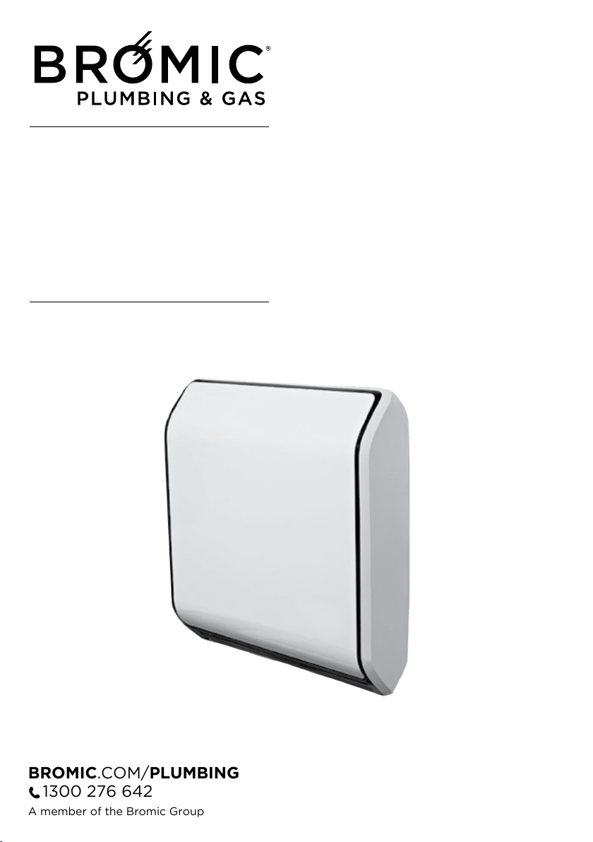
BROMIC FLUED INDOOR GAS HEATER
STRATOS 3.0 / 5.0 / 7.0 / 9.0
BROMIC.COM/PLUMBING
1300 276 642
A member of the Bromic Group
July 2019 - V1
PRODUCT IMAGE
INSTALLATION, INSTRUCTION
AND SERVICE MANUAL
BROMIC FLUED INDOOR GAS HEATER
BROMIC BRAHMA STRATOS 3.0 / 5.0 / 7.0 / 9.0
August 2019-v1.1
Flued Indoor Gas Heater - Instruction Manual
2
July 2019 - V1
PLUMBING & GAS
2
GENERAL
COMPLIANCE
RANGE
2
GENERAL
COMPLIANCE
RANGE
2
GENERAL
COMPLIANCE
RANGE
Head Ofce: 10 Phiney Place, Ingleburn, Sydney, NSW 2565 Australia
Telephone: 1300 276 642 (within Australia) or NZ 0508 276 642
Email: [email protected] Web: www.bromic.com/plumbing
Note: Bromic Plumbing Pty Ltd reserves the right to make changes to specications, parts,
components and equipment without prior notication. This Installation, operation and service manual
may not be reproduced in any form without prior written consent from Bromic Plumbing Pty Ltd.
This manual contains important information about the assembly, operation, and maintenance of
Blow Heaters. Please pay close attention to the important safety information shown
throughout this instruction manual. Any safety information will be accompanied
by the following safety alert symbols:
DANGER, WARNING, IMPORTANT
!
!
!
MODEL CODE
BRAHMA STRATOS 3.0 NG 2620970
BRAHMA STRATOS 5.0 NG 2620971
BRAHMA STRATOS 7.0 NG
2620972
BRAHMA STRATOS 9.0 NG 2620973
Flued Indoor Gas Heater - Instruction Manual
2
July 2019 - V1
PLUMBING & GAS
2
GENERAL
COMPLIANCE
RANGE
2
GENERAL
COMPLIANCE
RANGE
2
GENERAL
COMPLIANCE
RANGE
Head Ofce: 10 Phiney Place, Ingleburn, Sydney, NSW 2565 Australia
Telephone: 1300 276 642 (within Australia) or NZ 0508 276 642
Note: Bromic Plumbing Pty Ltd reserves the right to make changes to specications, parts,
components and equipment without prior notication. This Installation, operation and service manual
may not be reproduced in any form without prior written consent from Bromic Plumbing Pty Ltd.
This manual contains important information about the assembly, operation, and maintenance of
Blow Heaters. Please pay close attention to the important safety information shown
throughout this instruction manual. Any safety information will be accompanied
by the following safety alert symbols:
DANGER, WARNING, IMPORTANT
!
!
!
MODEL CODE
BRAHMA STRATOS 3.0 NG 2620970
BRAHMA STRATOS 5.0 NG 2620971
BRAHMA STRATOS 7.0 NG
2620972
BRAHMA STRATOS 9.0 NG 2620973
MODEL CODE
STRATOS BRAHMA 3.0 NG 2620970
STRATOS BRAHMA 5.0 NG 2620971
STRATOS BRAHMA 7.0 NG
2620972
STRATOS BRAHMA 9.0 NG 2620973
Flued Indoor Gas Heater - Instruction Manual
2
July 2019 - V1
PLUMBING & GAS
2
GENERAL
COMPLIANCE
RANGE
2
GENERAL
COMPLIANCE
RANGE
2
GENERAL
COMPLIANCE
RANGE
Head Ofce: 10 Phiney Place, Ingleburn, Sydney, NSW 2565 Australia
Telephone: 1300 276 642 (within Australia) or NZ 0508 276 642
Note: Bromic Plumbing Pty Ltd reserves the right to make changes to specications, parts,
components and equipment without prior notication. This Installation, operation and service manual
may not be reproduced in any form without prior written consent from Bromic Plumbing Pty Ltd.
This manual contains important information about the assembly, operation, and maintenance of
Blow Heaters. Please pay close attention to the important safety information shown
throughout this instruction manual. Any safety information will be accompanied
by the following safety alert symbols:
DANGER, WARNING, IMPORTANT
!
!
!
MODEL CODE
BRAHMA STRATOS 3.0 NG 2620970
BRAHMA STRATOS 5.0 NG 2620971
BRAHMA STRATOS 7.0 NG
2620972
BRAHMA STRATOS 9.0 NG 2620973
GENERAL
General informations pag.5
Safety rules pag.5
Appliance description pag.6
Identification pag.6
Structure pag.7
Technical data pag.8
Accessories pag.8
Electrical scheme pag.9
Control panel pag.10
INSTALLATION
Receiving the product pag.11
Weight and dimension pag.12
Installation: WALL FITTING or FLOOR STANDING
- Apparatus choice location pag.13
- Intake & exhaust tube fumes assemblage pag.14
-- Tube Kit Ø 32 o Ø 54 mm
with unique term. (Standard) pag.16
KIT “FLOOR STANDING” support structure pag.18
KIT “PROTECTION FOR WALLS MADE OF WOOD PANELS” pag.19
Electrical collegaments pag.20
Gas connection pag.20
CUSTOMER SERVICE
Preliminary operations pag.21
First service start pag.21
Processor control box malfunction pag.22
Controls during the first & after starting service pag.22
Gas transformation pag.23
Regolation pag.24
Ordinary maintena
nce pag.25
Appliance clean out pag.25
Components replacement pag.26
Disassembly & reassembly of the casing pag.30
Eventual anomalies & remedies pag.30
Useful information pag.32
4
GENERAL
INDEX
Flued Indoor Gas Heater - Instruction Manual
3
GENERAL
General informations pag.5
Safety rules pag.5
Appliance description pag.6
Identification pag.6
Structure pag.7
Technical data pag.8
Accessories pag.8
Electrical scheme pag.9
Control panel pag.10
INSTALLATION
Receiving the product pag.11
Weight and dimension pag.12
Installation: WALL FITTING or FLOOR STANDING
- Apparatus choice location pag.13
- Intake & exhaust tube fumes assemblage pag.14
-- Tube Kit Ø 32 o Ø 54 mm
with unique term. (Standard) pag.16
KIT “FLOOR STANDING” support structure pag.18
KIT “PROTECTION FOR WALLS MADE OF WOOD PANELS” pag.19
Electrical collegaments pag.20
Gas connection pag.20
CUSTOMER SERVICE
Preliminary operations pag.21
First service start pag.21
Processor control box malfunction pag.22
Controls during the first & after starting service pag.22
Gas transformation pag.23
Regolation pag.24
Ordinary maintena
nce pag.25
Appliance clean out pag.25
Components replacement pag.26
Disassembly & reassembly of the casing pag.30
Eventual anomalies & remedies pag.30
Useful information pag.32
4
GENERAL
INDEX
GENERAL
General informations pag.5
Safety rules pag.5
Appliance description pag.6
Identification pag.6
Structure pag.7
Technical data pag.8
Accessories pag.8
Electrical scheme pag.9
Control panel pag.10
INSTALLATION
Receiving the product pag.11
Weight and dimension pag.12
Installation: WALL FITTING or FLOOR STANDING
- Apparatus choice location pag.13
- Intake & exhaust tube fumes assemblage pag.14
-- Tube Kit Ø 32 o Ø 54 mm with unique term. (Standard) pag.16
KIT “FLOOR STANDING” support structure pag.18
KIT “PROTECTION FOR WALLS MADE OF WOOD PANELS” pag.19
Electrical collegaments pag.20
Gas connection pag.20
CUSTOMER SERVICE
Preliminary operations pag.21
First service start pag.21
Processor control box malfunction pag.22
Controls during the first & after starting service pag.22
Gas transformation pag.23
Regolation pag.24
Ordinary maintenance pag.25
Appliance clean out pag.25
Components replacement pag.26
Disassembly & reassembly of the casing pag.30
Eventual anomalies & remedies pag.30
Useful information pag.32
4
GENERAL
INDEX
GENERAL
General informations 4
Safety rules 4
Appliance description 5
Identication 5
Structure 6
Technical data 7
Accessories 7
Electrical scheme 8
Control panel 9
INSTALLATION
Receiving the product 10
Weight and dimension 11
Installation: WALL FITTING or FLOOR STANDING
- Apparatur choice location 12
- Intake & exhaust tube fumes assemblage 13
--Tube Kit 32-54 mm with unique term (Standard) 15
KIT “FLOOR STANDING” support structure 17
KIT “PROTECTION FOR WALLS MADE OF WOOD PANELS” 18
Electrical collegaments 19
Gas connection 19
CUSTOMER SERVICE
Preliminary operations 20
First service start 20
Processor control box malfunction 21
Controls during the rst & after starting service 21
Gas transformation 22
Regolation 23
Ordinary maintenance 24
Appliance clean out 24
Components replacement 25
Disassembly & reassembly of the casing 27
Eventual anomalies & remedies 27
Useful information 31
Flued Indoor Gas Heater - Instruction Manual
4
We like to remember that, products that use combustion
or electrical energy there is security rule to observe
before operating.
Do not allow children to be near the appliance.
It is prohibited to turn on an electrical device if there
is a gas smell.
In this case:
- Open windows and door.
- Close the gas tap.
- Call a Technical Service Assistance.
It is prohibited to touch the appliance with wet hand
or othe
r parts of your body.
-Electrical Hazard: Do not touch the appliance with
wet feet or other part of your body.
It is prohibited to clean the appliance when it is run-
ning.
It is prohibited to pull, remove and wring electric
wires outside the appliance also if the electrical
supply is turned off.
It is prohibited place over the appliance, towels, tea
clothes and other could be cause of inefficiency or
also
source of hazard.
It is prohibited to leave paper, plastic, or other things
of the appliance box outside within a child’s reach.
It could be potential source of hazard.
After removing the packaging, check the integrity of
the contents. In case of discrepancies, contact the
Agency that sold the appliance.
The APPLIANCE must be used as intended by the
Manufacturer and for the purpose for which it was
expressly built.
The Manufacturer disclaims any contractual and
non-contractual liability for injury to persons and ani-
mals and damage to things caused by installation,
adjus
tment and maintenance errors or improper
appliance use.
If the APPLIANCE is not used for a long period of
time, the following operations will have to be perfor-
med:
- position the master switch of the appliance on
"OFF"
- position the master switch of the system, if fitted, on
"OFF" or disconnect the plug from the power socket.
- close the gas tap
The appliance should be serviced at least once a
year.
This b
ooklet is an integral part of the appliance and
must theref ore be carefully l ooked a fter an d
ALWAYS accompany the APPLIANCE, including
when this is sold to another user or transferred to
another system.
In case of damage or loss, ask the Area After Sales
service of the Manufacturer for another copy.
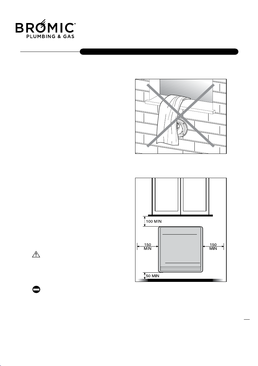
Always make sure that curtains or other objects do
not obstruct the suction filter and the room air outlet
v
ent.
Only connect the appliance to properly earthed
power sockets.
Only install the appliance in dry environments (pro-
tection IP 20)
The appliance must not be operated wherever there
are hazardous materials, vapours or liquids.
Install the appliance on a flat surface to prevent any
malfunction.
5
GENERAL
GENERAL INFORMATIONS
SAFETY RULES
GENERAL
General informations pag.5
Safety rules pag.5
Appliance description pag.6
Identification pag.6
Structure pag.7
Technical data pag.8
Accessories pag.8
Electrical scheme pag.9
Control panel pag.10
INSTALLATION
Receiving the product pag.11
Weight and dimension pag.12
Installation: WALL FITTING or FLOOR STANDING
- Apparatus choice location pag.13
- Intake & exhaust tube fumes assemblage pag.14
-- Tube Kit Ø 32 o Ø 54 mm
with unique term. (Standard) pag.16
KIT “FLOOR STANDING” support structure pag.18
KIT “PROTECTION FOR WALLS MADE OF WOOD PANELS” pag.19
Electrical collegaments pag.20
Gas connection pag.20
CUSTOMER SERVICE
Preliminary operations pag.21
First service start pag.21
Processor control box malfunction pag.22
Controls during the first & after starting service pag.22
Gas transformation pag.23
Regolation pag.24
Ordinary maintena
nce pag.25
Appliance clean out pag.25
Components replacement pag.26
Disassembly & reassembly of the casing pag.30
Eventual anomalies & remedies pag.30
Useful information pag.32
4
GENERAL
INDEX
Flued Indoor Gas Heater - Instruction Manual
4
We like to remember that, products that use combustion
or electrical energy there is security rule to observe
before operating.
Do not allow children to be near the appliance.
It is prohibited to turn on an electrical device if there
is a gas smell.
In this case:
- Open windows and door.
- Close the gas tap.
- Call a Technical Service Assistance.
It is prohibited to touch the appliance with wet hand
or othe
r parts of your body.
-Electrical Hazard: Do not touch the appliance with
wet feet or other part of your body.
It is prohibited to clean the appliance when it is run-
ning.
It is prohibited to pull, remove and wring electric
wires outside the appliance also if the electrical
supply is turned off.
It is prohibited place over the appliance, towels, tea
clothes and other could be cause of inefficiency or
also
source of hazard.
It is prohibited to leave paper, plastic, or other things
of the appliance box outside within a child’s reach.
It could be potential source of hazard.
After removing the packaging, check the integrity of
the contents. In case of discrepancies, contact the
Agency that sold the appliance.
The APPLIANCE must be used as intended by the
Manufacturer and for the purpose for which it was
expressly built.
The Manufacturer disclaims any contractual and
non-contractual liability for injury to persons and ani-
mals and damage to things caused by installation,
adjus
tment and maintenance errors or improper
appliance use.
If the APPLIANCE is not used for a long period of
time, the following operations will have to be perfor-
med:
- position the master switch of the appliance on
"OFF"
- position the master switch of the system, if fitted, on
"OFF" or disconnect the plug from the power socket.
- close the gas tap
The appliance should be serviced at least once a
year.
This b
ooklet is an integral part of the appliance and
must theref ore be carefu lly looked after and
ALWAYS accompany the APPLIANCE, including
when this is sold to another user or transferred to
another system.
In case of damage or loss, ask the Area After Sales
service of the Manufacturer for another copy.
Always make sure that curtains or other objects do
not obstruct the suction filter and the room air outlet
v
ent.
Only connect the appliance to properly earthed
power sockets.
Only install the appliance in dry environments (pro-
tection IP 20)
The appliance must not be operated wherever there
are hazardous materials, vapours or liquids.
Install the appliance on a flat surface to prevent any
malfunction.
5
GENERAL
GENERAL INFORMATIONS
SAFETY RULES
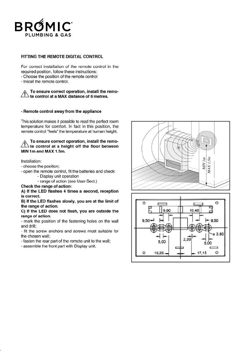
Do not spray aerosols in the vicinity of this
appliance while it is in operation.
Do not use or store flammable materials in or
near this appliance.
Do no place articles on or against this appliance.
Do not modify this appliance.
Flued Indoor Gas Heater - Instruction Manual
5
July 2019 - V1
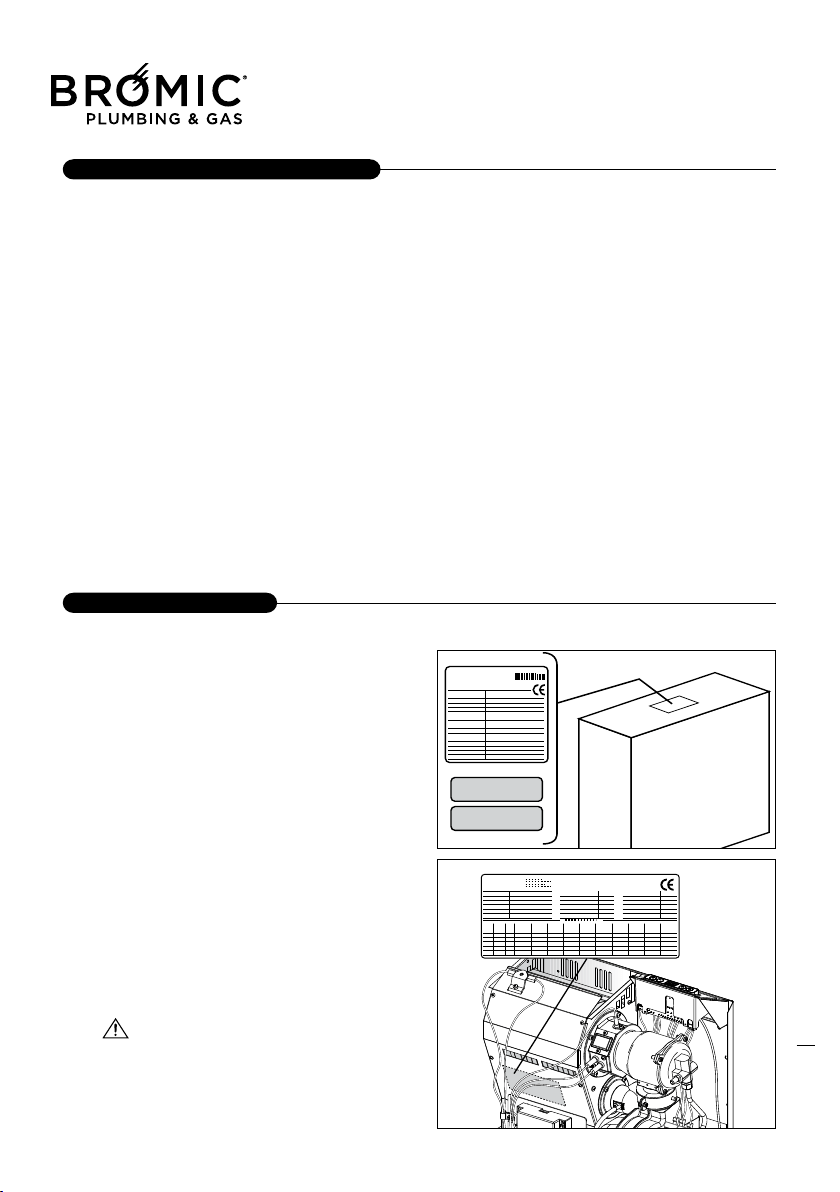
The appliance is identified through:
- Packed label:
A label that indicates the code and the combustion it
uses to identifies the appliance.
- Technical label:
The technical label reports the matrices numbers,
the gas prearrangement, and technical observation.
-Gas prearrangement label:
It reports the kind of gas the appliance has to use,
and if there is a transformation from one kind of gas
to another you
have to change the old label.
Spare parts, or technical operation require, a
precise identification of the type of model.
If there is going to be any tampering of the technical
label, this will not consent the right identification of
the apparatus.
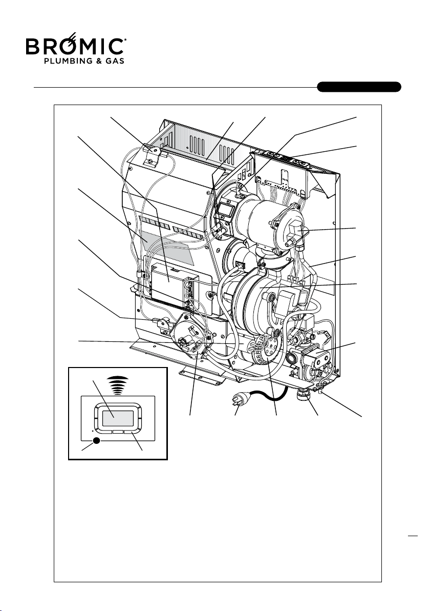
The appliance is a gas radiator that heat up the
atmosphere.
It has an intake of air that goes in the combustion
chamber type C.
The appliance is made with an aluminium body that
allows a high efficiency of heat; it also has a fan that
allows the dispersal of air faster in the rooms.
The appliances are arranged in factory for the func-
tion at gas methane and they can be transformed to
GPL(G30/G31) using t
he furnished nozzle kit.
Note: At request the apparatus can be furnished
already arranged at GPL.
It also has an electrical device that allows you to do
a series of things.
There also is a Processor Control Box (P.C.B
assy) that controls all the principals’ function of
the apparatus.
After there is the Control Panel that has other
options.
6
GENERAL
APPLIANCE DESCRIPTION
IDENTIFICATION
Flued Indoor Gas Heater - Instruction Manual
6
July 2019 - V1
7
GENERAL
STRUCTURE
Flued Indoor Gas Heater - Instruction Manual
7
July 2019 - V1
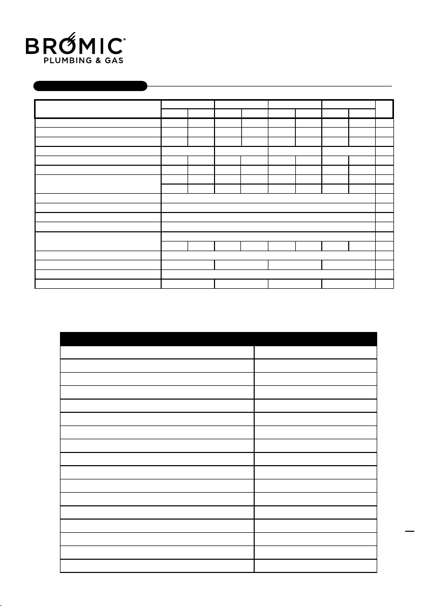
8
GENERAL
TECHNICAL DATA
ACCESSORIES
°
°
°
°
°
°
°
DESCRIPTION CODE
Comando Wireless 2620980
Stratos Timer - Wireless Remote 2620981
1000mm Flue 32mm dia. (70000710) 2620982
1000mm Flue 54mm dia. (70000380) 2620983
290° Aluminium Bend 54mm dia. (70000370) 2620984
Floor Standing Kit 3.0 (233628) 2620985
Floor Standing Kit 5.0 (233629) 2620986
Floor Standing Kit 9.0 (233631) 2620987
HT Armaex 32mm (70000840) 2620988
HT Armaex 54mm (70000850) 2620989
Stratos 32mm Flue Cowl (70000466) 2620990
Stratos 32mm Flue Terminal (80006900) 2620991
Stratos 54mm Flue Terminal (80006915) 2620992
Stratos 90° Elbows 32mm (7000700) 2620993
Stratos Chimney 54mm Dia (70000740) 2620994
Stratos Flue Guard (3.0 & 5.0) (70000600) 2620995
Stratos Short Radius 90° Bend - 54mm dia (70000740) 2620996
Flued Indoor Gas Heater - Instruction Manual
8
July 2019 - V1
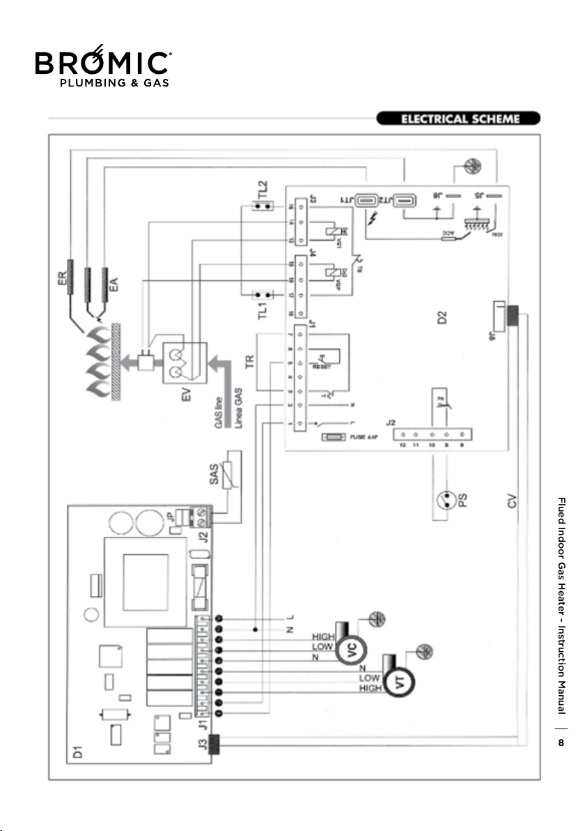
Flued Indoor Gas Heater - Instruction Manual
9
July 2019 - V1
10
GENERAL
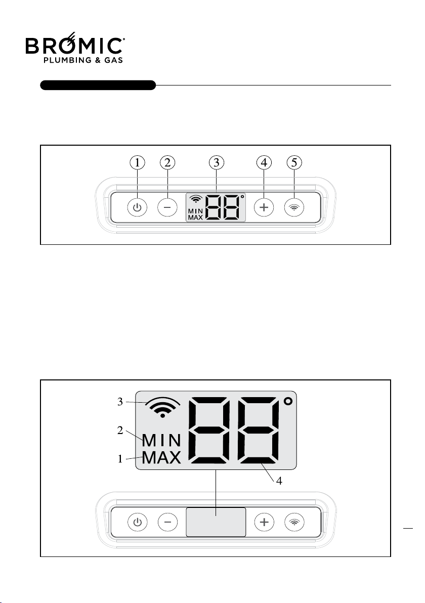
CONTROL PANEL
DESCRIPTION OF DISPLAY
This type of screen simultaneously provides an
entire series of information:
- MIN operating power.
- MAX operating power.
- Wire command enabling.
- ambient temperature.
- desired ambient temperature.
- degrees centigrade unit scale.
- data transmission
DESCRIPTION OF ICONS
1 - operation at MAX power.
2 - operation at MIN power.
3 - data transmission between the device and
the Wireless
command (intermittent icon).
3b - Wireless command enabled (fixed on
icon).
4 - Detected ambient temperature.
4b - Desired ambient temperature.
1 - On/Off key and device RESET
2 - Reduce temperature key (MIN 5°C)
3 - Light display
4 - Increase temperature key (MAX 35°C)
5 - Enable/disable Wireless command key
Flued Indoor Gas Heater - Instruction Manual
10
July 2019 - V1
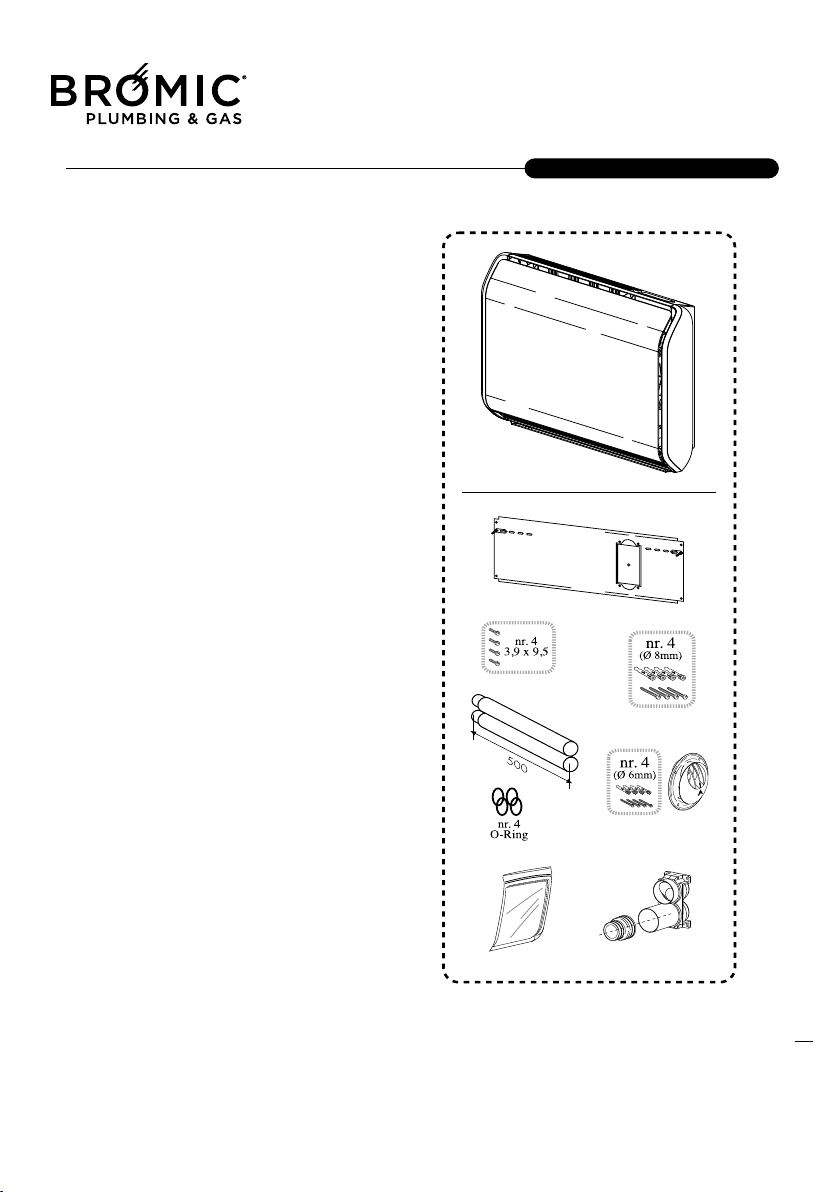
The appliance is supplied in one cardboard package:
Contents of appliance package:
1 Appliance
1 Manual control
1 Metal template
1 Pipe KIT:
1 Adapter union
1 Suction pipe (L = 500mm)
(Ø 32mm Mod. 3.0 - 5.0)
(Ø 54mm Mod. 7.0 - 9.0)
1 exhaust pipe (L = 500mm)
(Ø 32mm Mod. 3.0 - 5.0)
(Ø 54mm Mod. 7.0 - 9.0)
1 Single outer end piece + anchors
(Ø 32mm Mod. 3.0 - 5.0)
(Ø 54mm Mod. 7.0 - 9.0)
1 Document envelope:
1 Operator
's instruction booklet
1 Installer's instruction booklet
1 Gas transformation kit
1 Spare parts catalogue
1 Warranty certificate
1 Warranty labels
1 Power socket
1 Paper template
11
INSTALLER
RECEIPT OF PRODUCT
Flued Indoor Gas Heater - Instruction Manual
11
July 2019 - V1
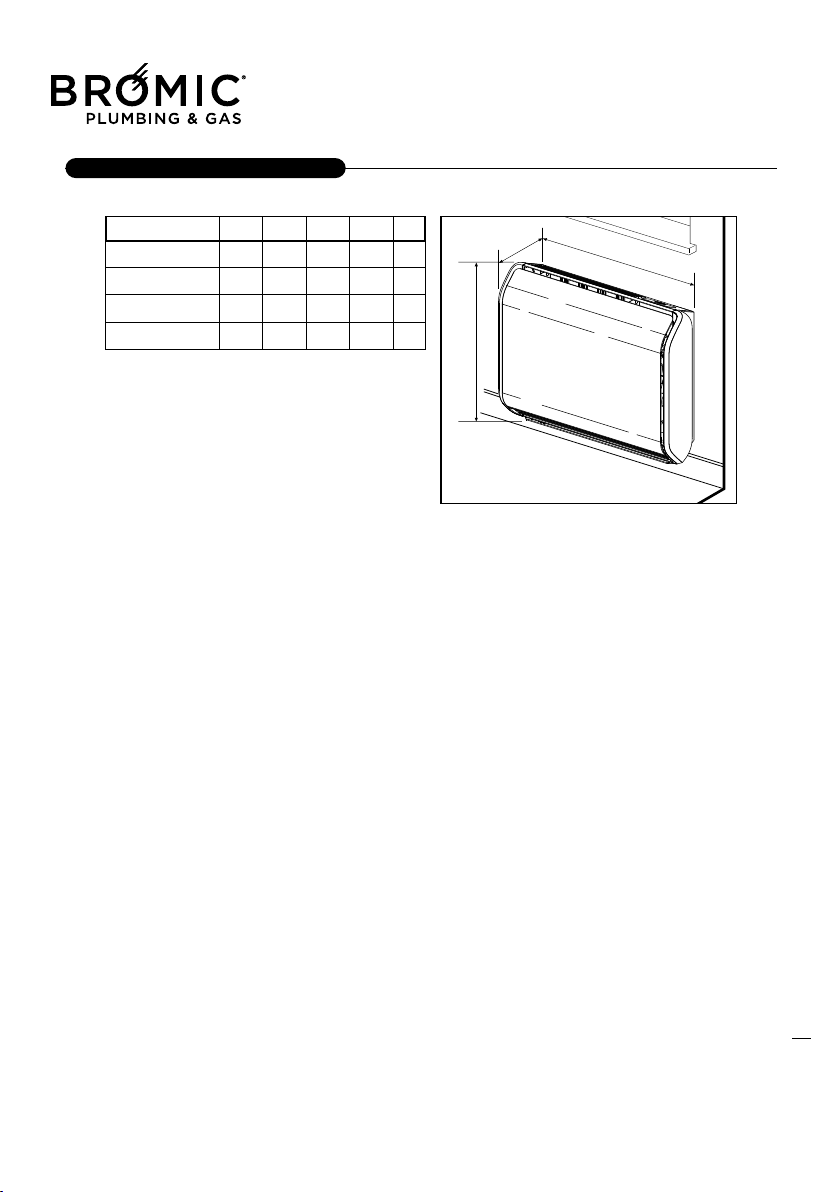
12
INSTALLER
WEIGHT & DIMENSION
Flued Indoor Gas Heater - Instruction Manual
12
July 2019 - V1
GENERAL INFORMATIONS
This apparatus is tin respect to the environment; the
air is intake from the outside.
-When the appliance is being installed do not use
other pieces that are not give from the manufacturer.
-Don’t let the electrical cable touch heated parts, like
the grill or the intake & exhaust tubes.
Is the installation duty to tell the owner the behaviour
to keep during the apparatus function.
-Do
n’t block with cloths or rug the apparatus intake &
exhaust tubes.
APPARATUS CHOICE LOCATION
Before you’re going to install the appliance, check if
there is enough space for the correct function of the
appliance.
Check if around the appliance tubes there are mate-
rials that can support the heath, second check if the
wall is made of the right material and can support the
appliance weight.
Verified if around
the exhaust fumes tubes, there is
no wood or plastic but there is the right material that
can support the heath.
The material where the appliance it going to be pla-
ced has to resist the exhaust tube heath (about
180°C).
In case of low resistant wall material it’s possi-
ble to realize a cavity around the exhaust fume
tube, and insulate with strong material for the pre-
sent temperature, otherwise execut
e a hole with a
larger diameter at least 4 cm respect to the exhaust
fume tube.
Its prohibited settles the appliance in rooms like
bath, or showers. For this installation you need
to realize special protections that make the appara-
tus consistent to the Electrical security rules.
INSTALLATION: WALL FITTING or FLOOR STANDING
13
INSTALLER
Flued Indoor Gas Heater - Instruction Manual
13
July 2019 - V1
14
INSTALLER
INTAKE AND EXHAUST TUBE FUMES ASSEM-
BLAGE
The intake & exhaust tubes can be embedded insi-
de the wall, or in sight, they have to be protected to
avoid, risk condition. To have the apparatus in sight
it exist a spacing bar so that you can see the tubes,
we recommend that the exhaust tubes have to
have a good insulation using materials that have
also a resistan t of more 200° C° (ex. HT/-
Armaflex) of temper
ature. Realize the holes for
fastening the tubes, after establish the hangers’
length; insert it in the right position.
Before assembling the tubes kit verifying that the
Max tube length has been respected, even the
Max loaded loss provided (See table).
Flued Indoor Gas Heater - Instruction Manual
14
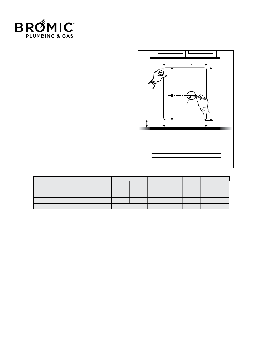
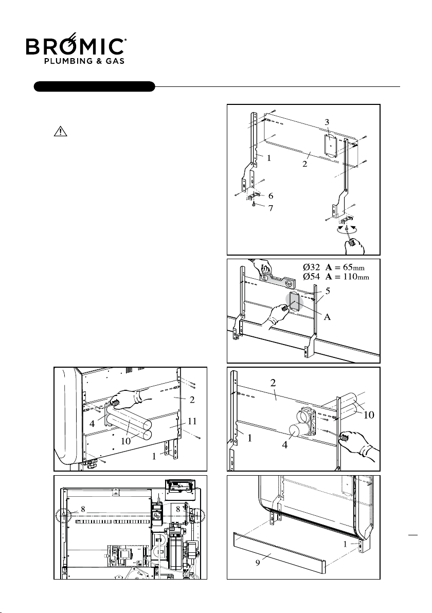
FITTING THE TEMPLATE, UNION AND PIPES
To determine the position of the APPLIANCE and of
the support template (3), use the paper template
(4) provided:
- level and mark the holes (1, 2), then remove the
paper template from the wall;
- make the holes (2) for fastening the template to the
wall;
- make the centring hole (1), through the entire wall
thickness;
- make the hole for the suction and discharge pipes
u
sing the centring hole (1);
Ø 65 mm hole for Ø 32 mm pipes or Ø 110 mm
hole for Ø 54 mm pipes.
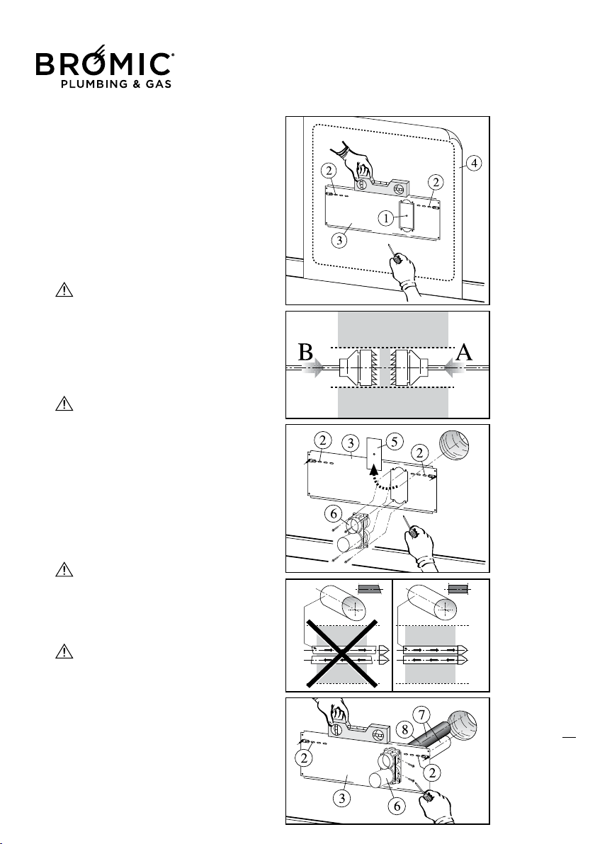
So as not to damage the outer part of the wall to
be drilled, we suggest making the hole in two
stages: starting from the inside (A) and ending on the
outer side (B).
- remove the plate (5);
- fit the adapter union unit (6) on the template, using
the screws provided;
- cut the pipes to the thickness of the wall ad
ding 25
mm, then eliminate the excess parts.
The cut must be perpendicular to the pipe
axis, being very careful not to deform these.
After cutting, carefully remove any burrs.
To make it easier to fit pipes with O-rings, use silico-
ne grease or a soapy solution and make sure the O-
rings do not exit from their seats.
In the event of the spacer support being used, the
template + unit + pipes must be faste
ned directly on
the support and the pipes must be fitted in the slots
provided on the support.
- fit and fasten the pipes (7) on the unit (6);
- level the template + unit + pipes;
- insulate the exhaust pipe (8) and fit the pipes in the
hole in the wall;
Before fastening the pipes, only for lengths
greater than 50cm, insulate the fume exhau-
st using material resistant to temperatures above
200 °C (e.g. HT/
-Armaflex).
- fasten the template + unit + pipes on the wall using
the screw anchors provided (2);
Use the screw anchors most suitable for
sustaining the weight and suitable for the
material of which the wall is made and to which it
is being fastened.
15
INSTALLER
Flued Indoor Gas Heater - Instruction Manual
15
16
INSTALLER
Outside grill assemblage GP and GPu
To assemble the grill you only need the inserts, and
the steeliness steel flange.
Assemblage SDP protection
The assembling is execute in the following way:
-After you have drilled on the outside wall put the
protection (1) with mortar
-Assemblage the terminal tube with the equipment
screws
-Adapt the terminal to the tube length and grill (2)
protection between the walls.
T
he tube cuts have to be perpendicular being real
careful do not deform.
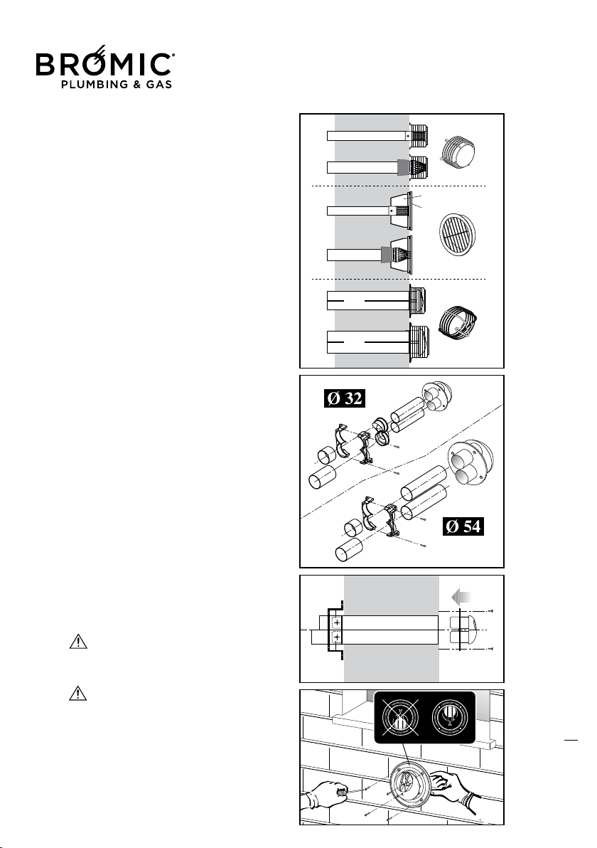
Kit parallel tube Ø 32/54 mm with unique terminal
(standard)
This kind of system is used when the exhaust fume
and the intake of air are next to the apparatus.
Assemblage the adapter tubes connection uni-
que terminal, from the out side.
-Insert in the wall the assembled group adapter con-
nection, angles, and curves.
Position the exhau
st/intake tubes at thread outside
wall, being real careful that the short tube is always
up (exhaust tube)
-Fasten the group adepter connection to the templa-
te with the screw set.
-Insert the unique terminal until the plastic ring tou-
ches the wall.
-Mark with a punch the holes for the fastening
-Cut the terminal then make the hole for the inserts
Ø 6 mm
-Fasten the unique terminal to the wall using the
inserts Ø 6mm seeing that the exhaust tube is
toward up.
Ascertain that the adapter tubes connections
are correctly inserted. To fasten the tubes
assemblage, use silicone grease and verified that
the O-ring don’t come out from there seating.
Befor e you wall up the tubes, only for
lengths greater than 50cm, provide to insula-
te the exhaust fume tube with material resistant
to the 200° C° (ex. HT/-Armaflex)
.
1
2
Ø32
Ø54
Ø32
Ø54
Ø32
Ø54
GP
SDP
GPu
Flued Indoor Gas Heater - Instruction Manual
16
July 2019 - V1
Flued Indoor Gas Heater - Instruction Manual
17
July 2019 - V1
18
INSTALLER
MOUNTING THE “FLOOR STANDING” SUPPORT
STRUCTURE
IMPORTANT! Read and respect the general
information of INSTALLATION chap.
The support structure kit is used when the wall selec-
ted for installation is unable to support the weight of
the appliance. Thanks to this accessory, all the wei-
ght of the appliance is discharged onto the floor.
Installation
- check the contents of the KIT;
- choose the installation wall and its actual consi-
stency for making the hole (A) for the suction and
exhaust pipes;
- assemble the side brackets (1) with the template
(2), supports (6) and the adjustment screws (7) so as
to create a single structure (5);
- move the single structure up against the wall and with
the help of a spirit level, make the centre of hole (A);
- make the hole (A);
Ø 65 mm hole for Ø 32 mm pipes or Ø 110 mm
hole for Ø 54 mm pipes.
- remove the plate (3) from the template (2);
- fit the unit (4) on the template (2);
- fit and fasten the pipes (10) on the unit (4);
- fit the new unit (structure + pipes) on the frame (11)
of the appliance;
- move the appliance up against the wall and level;
- fix the appliance to the wall with suitable wall plugs
using the holes (8).
- connect the power and gas supplies;
- fit the cover (9);
FLOOR STANDING
Flued Indoor Gas Heater - Instruction Manual
18
July 2019 - V1
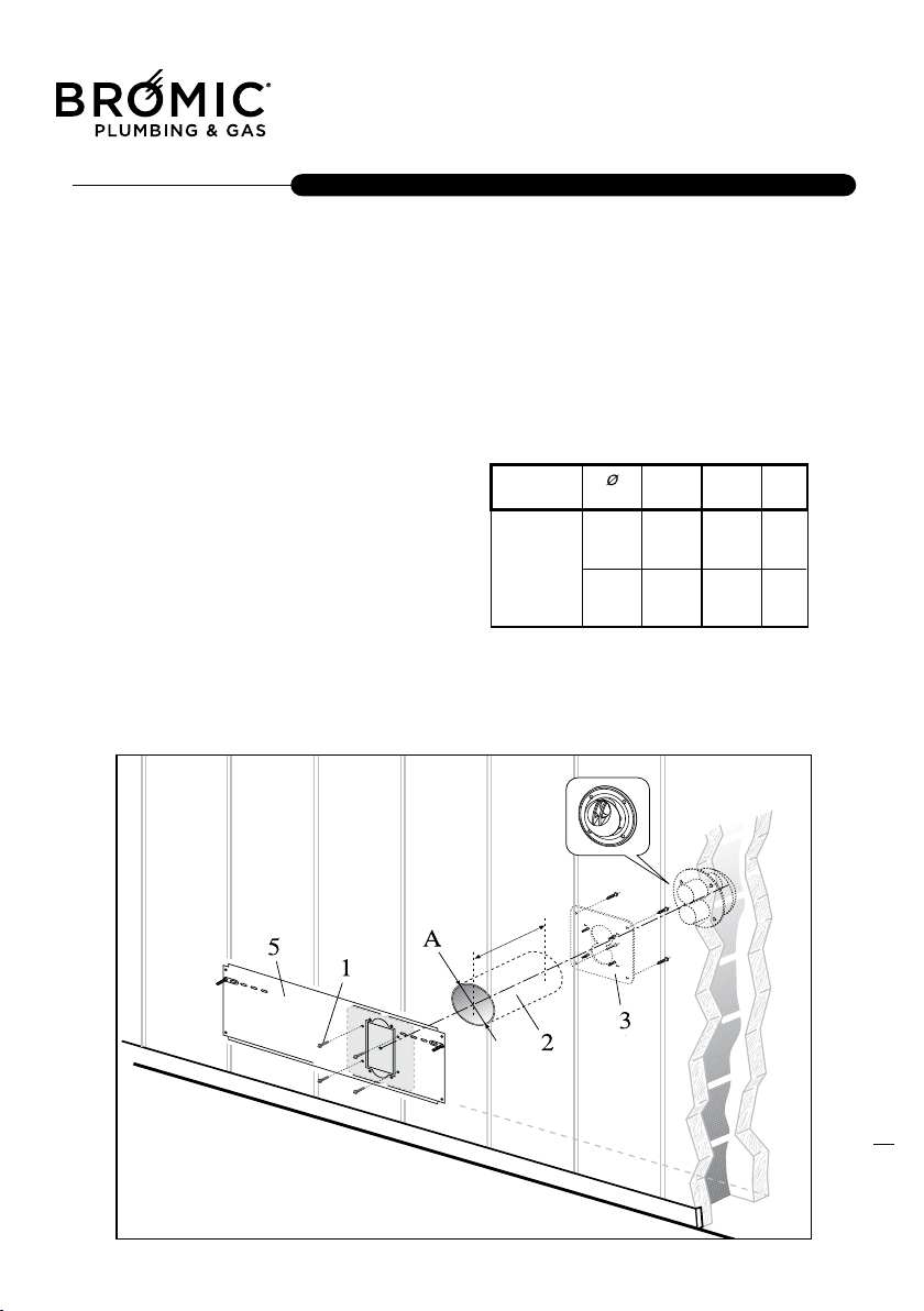
FITTING SILUMINA FRAME ASSEMBLY FOR
INSTALLATION ON COMBUSTIBLE OR WOODEN
WALL
This assembly is suitable for walls between 100 mm
and 500 mm thick.
- Having chosen the position for the heater in accor-
dance with the installation booklet for the heater, cut
a hole through the wall, with these dimensions: dia-
meter (A).
The hole in the wall as neatly as possible to enable
the flue assembly to be installed b
oth straight and
level through the wall.
- Fit the silumina frame assembly to the wall, as follows:
1) Measure the wall thickness, not including the
stainless-steel plate and cut the tube (2) to length
equal to the wall thickness.
Fit the internal tube, (2) inside the opening cut in the wall.
Fit the metal plate (5) to the inside of the wall, using
the 4 screws with anchors for wooden walls provi-
ded, for
fixing the plate on the wall. Fit the cut tube to
the wall working from inside the building, ensuring
that it fits within the lugs on the stainless-steel plate.
Fit the internal wall plate so that the 4 screws (1) on
it fit inside the tube.
2) Fit the external stainless - stell (3) AISI 304 to the
outside of the wall using the 4 screws, included in
the pack, if the external wall is hard stone chose
screw
s and anchors suitable for stone walls.
Use a water resistant compound (e.g. Secomasic or
Silastic) between the plate and the wall to prevent
rainwater reaching the interior of the wall.
PROTECTION FOR WALLS MADE OF WOOD PANELS
19
INSTALLER
Flued Indoor Gas Heater - Instruction Manual
19
20
INSTALLER
Check on the technical label that is on the heat
exchanger cover, for the kind of gas that the applian-
ce uses.
Use the proper gas tubes and pipe fitting. The
etching under the appliance is a 3/8" M UNI ISO 7/1.
When the gas alimentation, is on the right side
of the appliance for eventuating any problems
use a nipples.
After the gas connection is done, do the first
seal tests.
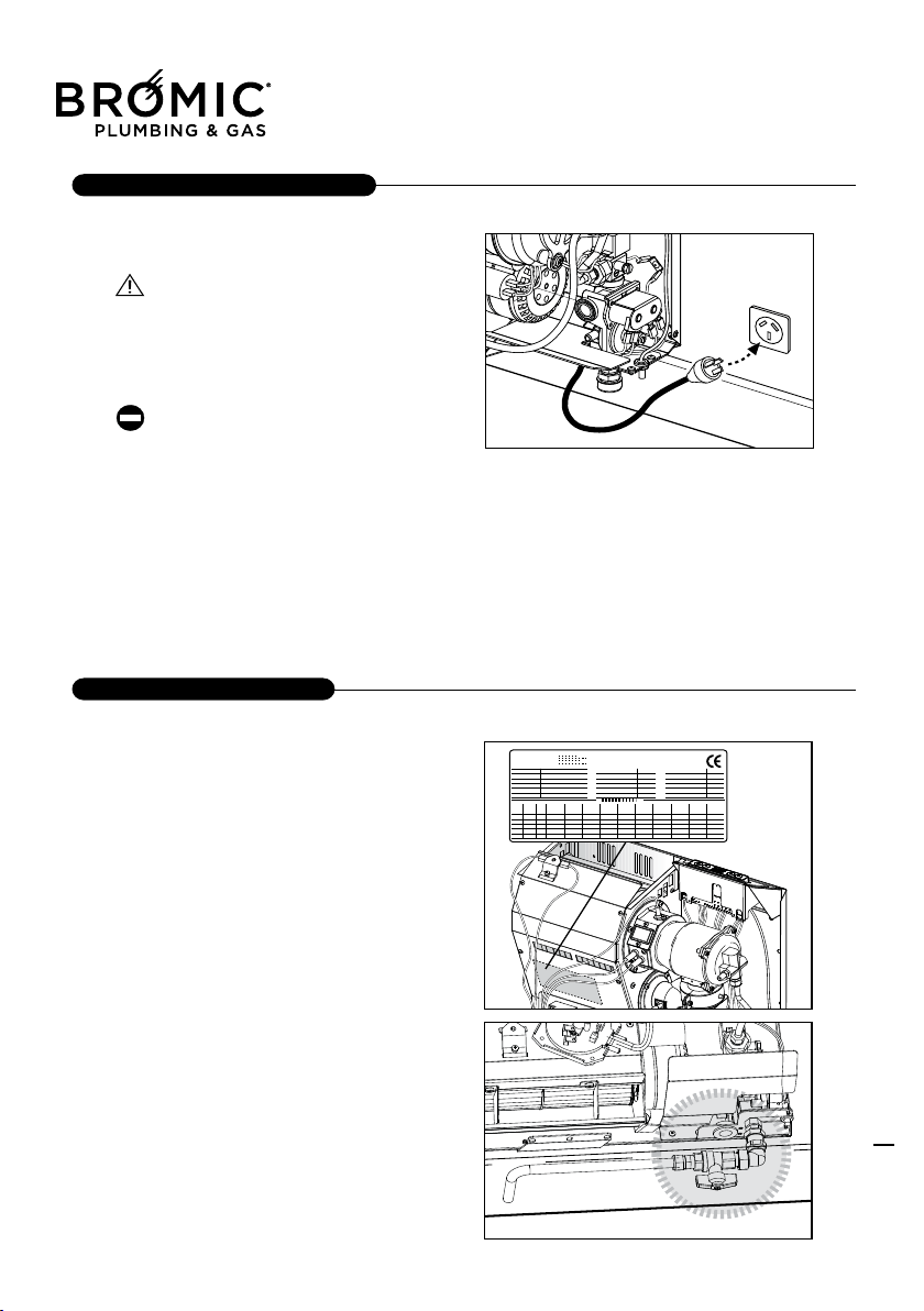
GAS CONNECTION
This apparatus is equipped with a cable with plug for
connection to the mains power supply.
A proper earth connection is mandatory.
The manufacturer of the appliance cannot be held
liable for any damage caused by lack of proper earth
connection.
For jobs of an electrical nature, always refer to the
diagram attached to this booklet.
Never use gas and/or water pipes to earth the
appliance.
POWER CONNECTIONS
Flued Indoor Gas Heater - Instruction Manual
20
July 2019 - V1
The appliance is furnished and preset for the gas
function (G 20) and regulated in factory.
Note: the apparatus can also be requested with the
GPL gas function.
First things to do before you start the appliance check:
- If the appliance is preset for the right gas
- The gas connection is correctly realized and the
gas switch is opened.
- The electrical connections are properly done.
Remember it is also imp
ortant to realize a good
ground connection and to respect the neutral phase.
During the first start, could be emissions of
vapors and odors annoying non dangerous. To
avoid these inconveniences, it is recommended to
run the unit at full power for several hours and ven-
tilate the room.
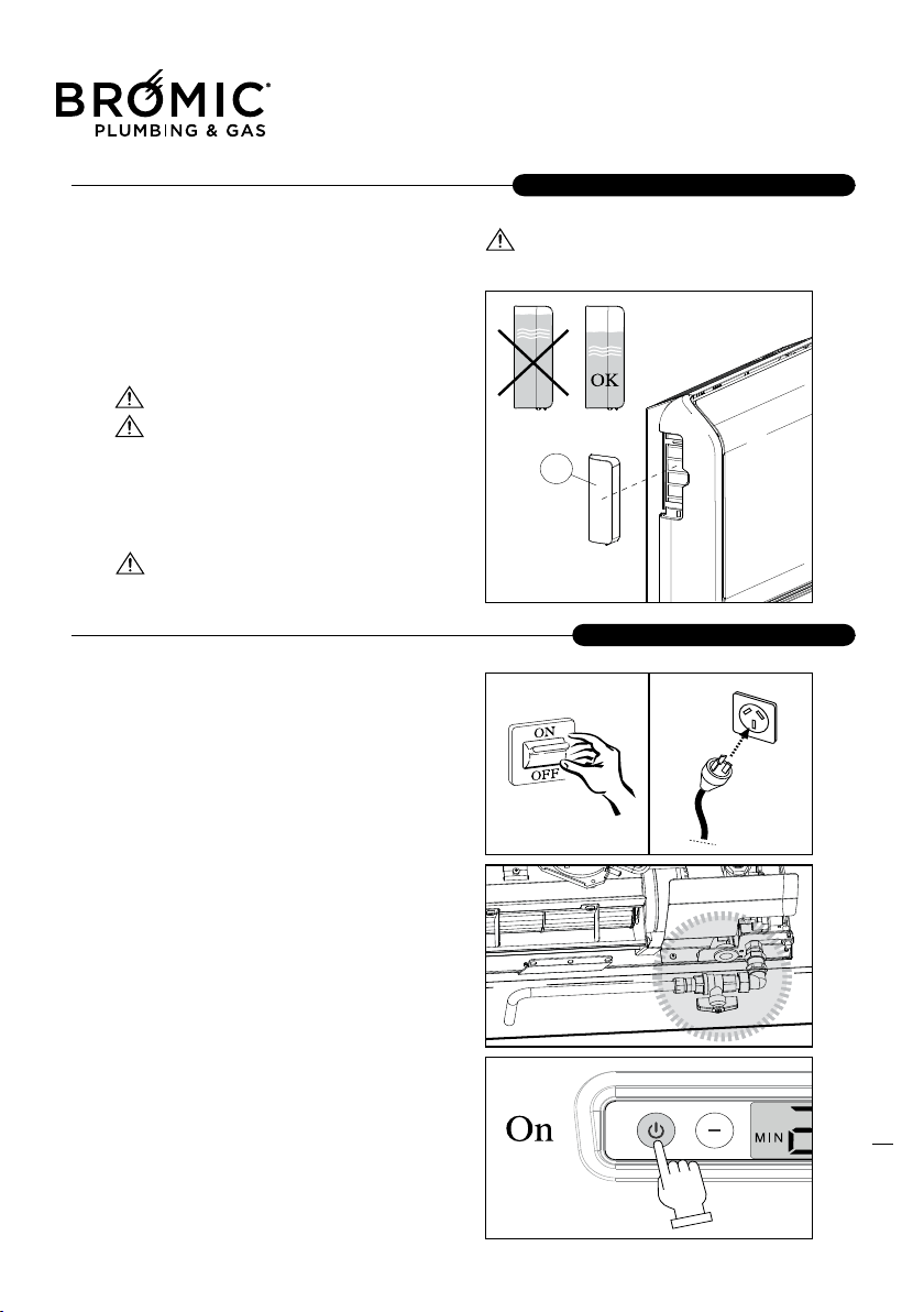
For greater comfort in the heated environment, we
advise using the humidifier tray (1) encased in the
casing.
Do not fill t
he tray to the top to prevent
water overflowing with consequent damage
to or malfunction of the appliance.
Only fill the tray with water. Avoid all other
liquids that could damage the tray or cause
appliance malfunctions.
After performing all the preparation operations for ini-
tial start-up, to start the appliance:
- make sure the fuel tap is open;
- plug into the power supply socket;
- move the master switch (if fitted) to "on" or fit the
power plug in the wall socket;
- press the On/Off key (see User section) to switch
on the appliance;
- set the room thermostat at a high value to reduce
heating time;
After startup, the
appliance runs until it reaches the
set room temperature.
In case of malfunctions in startup procedure or ope-
ration, the appliance STOPS and the relevant
unblock signal lights up on the display. Reset the
appliance by keeping the unblock button pressed.
Wait until the startup procedure is completed and the
operation signal lights up.
- When the appliance is running, set the clock and
the timer for automa
tic operation (see User section).
FIRST SERVICE START
PRELIMINARY OPERATIONS
21
CUSTOMER SERVICE
Flued Indoor Gas Heater - Instruction Manual
21
July 2019 - V1
22
CUSTOMER SERVICE
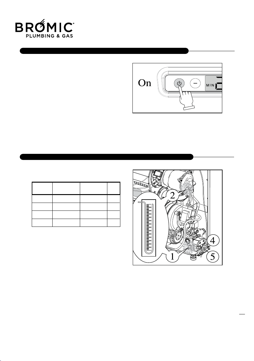
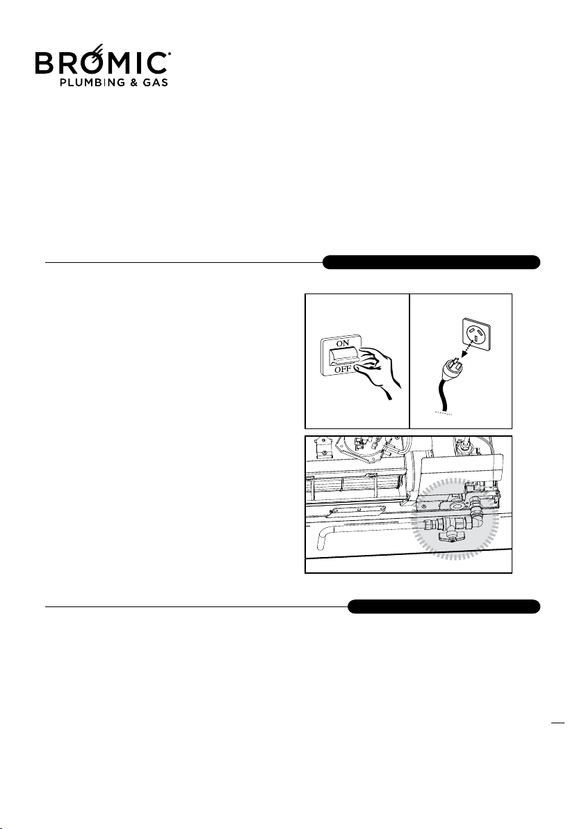
In case of any malfunctions in the control unit,
RESET as follows:
a - press the On/Off button as shown in the illustra-
tion.
b - connect and disconnect the plug from the socket
or move the master switch to “off” and then to “on”.
-At the start verified that the gas pressures are as
under the Table.
- The gas pressure value has to be as in the table.
- The apparatus execute a stop, and next restart.
--- Operating from the main control panel
--- Operate on the atmospheric thermostat or the
timer.
- The fan starts when thermostat gives the consent.
PROCESSOR CONTROL BOX (P.C.B ASSY) MALFUNCTION
CONTROLS DURING THE FIRST & AFTER STARTING SERVICE
Flued Indoor Gas Heater - Instruction Manual
22
July 2019 - V1
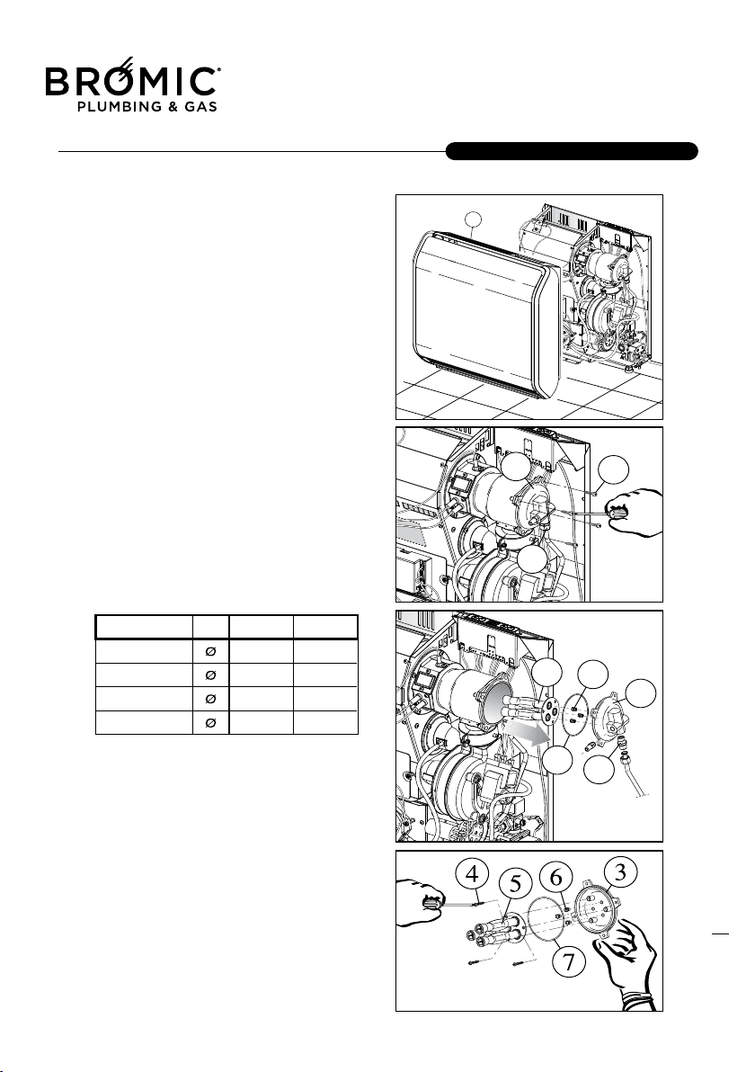
The appliance is prese t for the metha ne gas
(G20) following the technical label, but you can
change at GPL (G30/G31) with the transformation
that is furnished.
The transformation has to be done only by Technical
Service Assistance, the manufacturer or by authori-
zed persons even if appliance has been already
installed.
Shut down the appliance with the main button, and
then disconnect the electrical plug.
P
roceed to the disassembling of the cover (1) like
explained in the chapter assembling & disassembling
the cover.
Sequence apparitions
-To make the transformation you have to disconnect
the gas from the nipples R3/8 (1) that is on the cap.
- Take off the screws M5 (2) then slip off the cap and
the burner group (3).
- Unscrew the screws (4) and the burner (5).
- Unscrew the 3 injectors (6) change them with t
he
new ones. Be real careful when you fasten the injec-
tor, check on the injector that it has the right values
as in the table.
-The injectors seal and the nipples 3/8”, are realized
mechanically so you don’t need a gasket.
-Verifying that the values on the nozzles ore as in the
table below.
-Reassemble the cap with the burner, in the same
way that you dissembled don’t forget the O-ring (7)
that goes aroun
d the cap.
-Proceed to the regulation as indicated in the Cap.
Regulation; verified the tubes gas connections capa-
city that goes from the gas valve to the burner.
-Change the gas labels; seal the parts that you made
the regulation, after the transformation. Don’t forget
the old labels on the apparatus because it will cause
problems or danger.
GAS TRANSFORMATION
23
CUSTOMER SERVICE
Flued Indoor Gas Heater - Instruction Manual
23
July 2019 - V1
24
CUSTOMER SERVICE
The appliance is furnished with (G20) gas function
following the Technical label, and the constructor
already regulates it. If you make a new regulation,
like exchanging the gas valve, or a gas transforma-
tion from Methane to GPL or reversed, this regula-
tion has t o be done fro m a Technical service
Assistance or by the manufacture
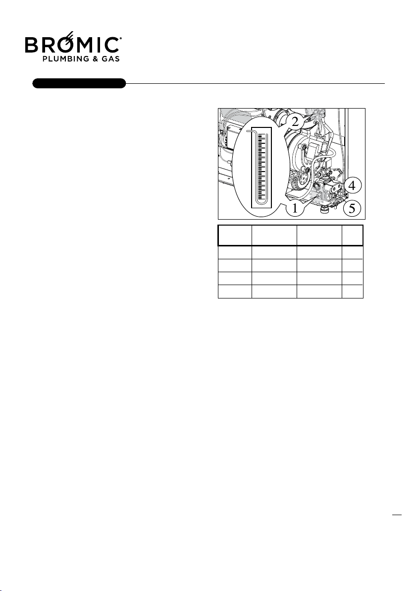
Gas methane G 20(20mbr); nominal & minimum
pressure regulation.
- Open t
he gas tap put the electrical plug under the
appliance then pushes the start button and put to the
max power.
Alimentation pressure
- Loosen the pressure screw (1) connect the mano-
meter and verified the pressure value is included
between 17/25mbar (like indicated in the table) then
close the screw after that the manometer tube is pul-
led away.
- Loosen the pressure screw (2) connect the mano-
meter veri
fied the nominal and minimum pressure
values are as specified in the table.
Nominal pressure
With the appliance in function at a max power loosen
the outlet pressure screw (2) then connect the mano-
meter and verified that the nominal pressure values
are as specified in the table (Nozzle Pressure). In the
GPL function, only for the 3+ categories the regulator
has to be out of service fastening clockwise t
he adju-
stment screw (1) at an immediately inferior value to
the alimentation max pressure.
At verification done, take away the manometer and
fasten the screw.
Minimum pressure
- Lift (On) the first switch to the left on this unit, so it
is working to "reduced power".
- Turn the idle screw (4).
Turn the screw counterclockwise, the pressure
increases, turning clockwise, the pressure decreases.
- Once adjuste
d, lowering the switch (off), disconnect
the manometer from the pressure tap and replace
the screw pressure reading.
- Completion of the adjustments, seal with a drop of
paint the screw on the regulator and the modulator.
- Disconnect the manometer from the pressure tap
and replace the screw.
Regulation GPL butane G30 (29mbar) and
Propane G31 (37mbar). Minimum and nominal
pressure.
- Open the gas taps put t
he electrical plug under the
appliance then push the start button and put to the
max power.
Alimentation pressure
- Loosen the pressure screw (1) connect the mano-
meter and verified the pressure value is included
between 29 mbar with the Butane and 37 mbar with
Propane then close the screw. In the case that the
net pressure is low, operate on the low-pressure
regulator that is put on the Gas tank.
- Verifi
ed that the establishment GPL vaporization
capacity is sufficient.
Nominal pressure
With the appliance in function at a max power loosen
the outlet pressure screw (2) then connect the mano-
meter and verified that the nominal pressure values
are as specified in the table (Nozzle Pressure). In the
GPL function, only for the 3+ categories the regulator
has to be out of service fastening clockwise the adju-
s
tment screw (1) at an immediately inferior value to
the alimentation max pressure.
At verification done, take away the manometer and
fasten the screw.
REGOLATION
Flued Indoor Gas Heater - Instruction Manual
24
July 2019 - V1
Whenever the apparatus is going to be regulated at
pure Propane, to avoid heat exchanger overheating,
is necessary knowing that you are using the proper
gas, but if you use a un proper gas like a mixture of
Propane/Butane or pure Butane you might have pro-
blems.
Regulation min pressure
Proceed to the minimum pressure regulation after
that you regulated the max pressure!
To make a regulation operate on the
screw that is on
the modulator body (4).
Rotating the regulator screw (3) clockwise the pres-
sure decrease, rotating counter clockwise the pres-
sure increases.
The appliance maintenance is important for the effi-
ciency and the reliability of the radiator. We recom-
mend that Technical Service Assistance perform the
maintenance once a year.
Preliminary operations:
-Disconnect the electrical alimentation; place the wall
switch to the “off” position.
-Close the gas tap.
-Wait that the appliance gets cold completely.
Cover clean
The only cleaning that is required by
the owner,
involves removing the cover, and wiping it clean the
dust, which may have collected.
Do not put grease or lubricants on any parts of the
appliance.
To clean plastic or painted parts don’t use any pro-
duct that will cause damage to the apparatus.
It is important that the switch is turned to the “off” posi-
tion on the control penal. Position the wall switch on off.
Wait that the appliance gets c
old completely
Do not allow water or any other liquid to be applied
directly to the cover, uses dampened clothes to do
the operation that you want.
Internal clean
For the correct disassembly and assembly see in the
relative section.
Burner clean out
If you want a good burner clean, especially if the
appliance has been working in dirty.
Places, or it didn’t work at all, use the compressor to
blow next to the injector; it will come out all the resi-
dues and the impurity caused from the burner.
Check all the injectors if are good.
Don’t use metallic ute
nsil.
ORDINARY MAINTENANCE
APPLIANCE CLEAN OUT
25
CUSTOMER SERVICE
Flued Indoor Gas Heater - Instruction Manual
25
July 2019 - V1
26
CUSTOMER SERVICE
Cleaning Electrode
The ignition electrode (1) and revelation (2) have to
be cleaned very carefully, after a period of time they
get fragile because of the work they have to perform.
- Unscrew the screws (3 o 4) and extract the electro-
de group (1 o 2) using a little brush with metallic hair
for cleaning, after insert the electrode group (1 o 2) if
necessary exchange the seal gasket (5) be real
careful to
not damage the electrode.
Pressure switch tubes
Check if there are deposits or condensation within
the pipes pressure measurement:
- Fan combustion air pressure switch.
- Exhaust fumes / pressure.
Blow, disconnect the switch and test it, otherwise,
may be damaged.
Preliminary operations:
-Disconnect the electrical alimentation taking off
the electrical plug; place the wall switch to the
“off” position.
-Clo
se the gas tap.
-Wait that the appliance gets cold completely.
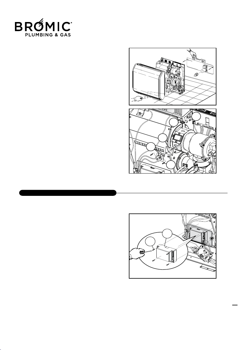
Replacing the Control board with Flame Control
To remove and refit the Flame Control board (1), fol-
low the instructions below:
- loosen the retention screw (2) of the board cover;
- remove the connectors from their plugs;
- completely replace the electronic board, taking care
to reconnect all the wires properly.
COMPONENTS REPLACEMENT
Flued Indoor Gas Heater - Instruction Manual
26
Replacing the room probe
Follow the instructions below to remove and refit the
probe:
- disconnect the connector of the probe cable (1)
from the control unit (2);
- take out the damaged probe;
- replace the component part and fit it back, perfor-
ming removal operations in the opposite sequence.
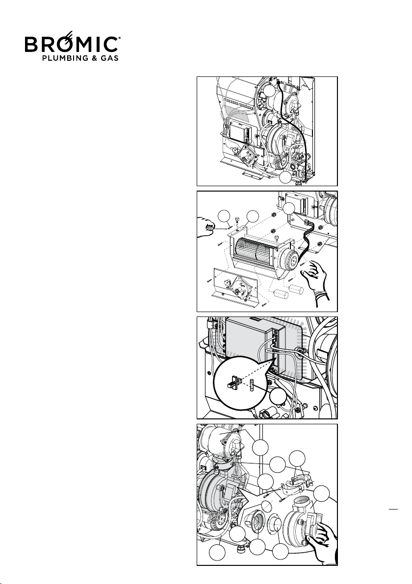
Replacing a convenction fan
Follow the indication to replace the fan
- Take off the electrical connectors (1) tha
t are on the
fan motor.
- Take off the ground connector that is on the fan
motor.
- Unscrew the 4 screws (2) that fasten the fan to the
supports (3)
- Replace the fan then after do the assemblage
Replacing a burnt out protection fuse
In the event of the appliance not switching back on
after a short circuit, immediately check the condition
of the protection fuse and proceed as follows:
- remove the fuse (1) a
nd check its condition. If it has
gone brown or the inside filament is broken, it will
have to be replaced with another of the rapid type:
F1AT- 250 V.
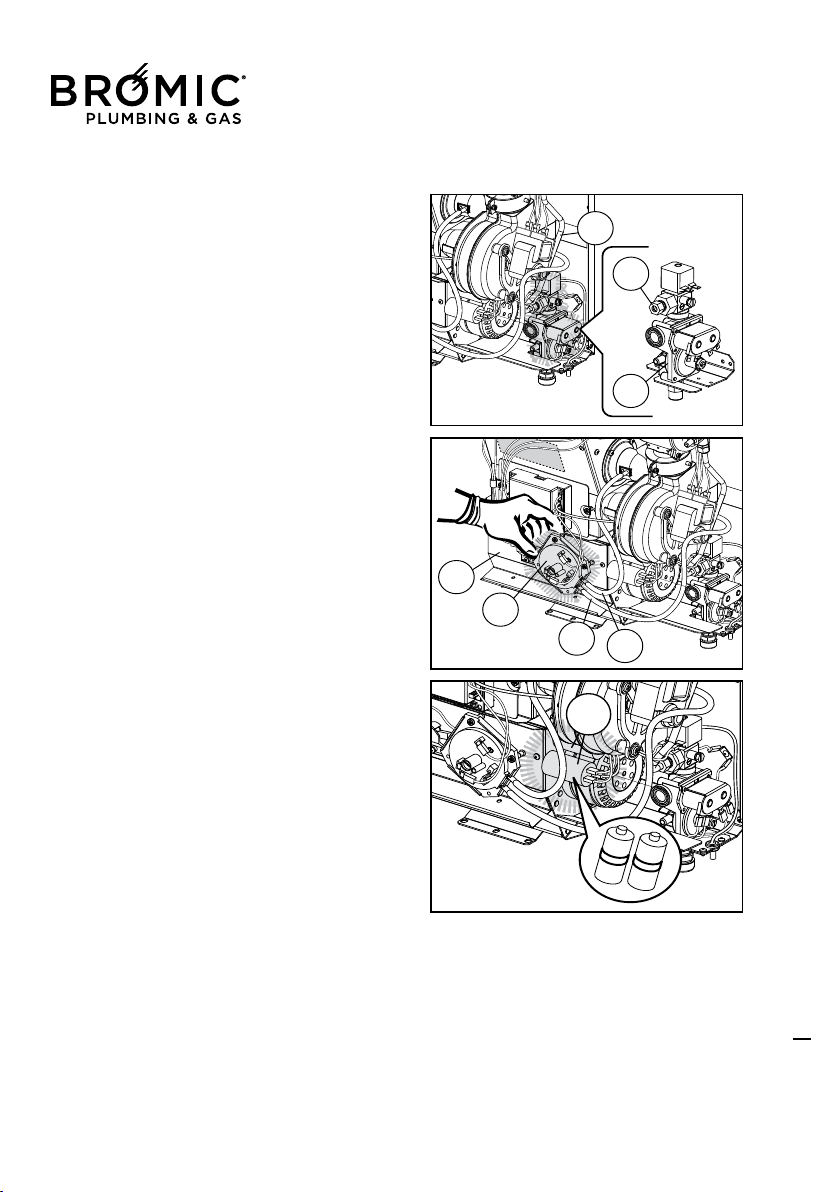
Comburant air fan replacement.
Follow the indication to replace the comb rent air fan.
- Take off the electrical connectors from the motor.
- Take off the electrical ground connectors from the motor.
- Remove the tube (1) from the pressure tap.
- Disassembl
e the clamp (2) unscrewing the screws (3)
divide the clamp with the sleeve in two parts (4) fasten the
fan metering screw (5) to the combustion chamber (6).
- Disassemble a half sleeve (4) with the clamp (2) and
after the fan (5).
- Unscrew the screw away the fan frame complete of
curves connector (7) and ant vibration gasket (8).
- Disassemble the curves connector (7) from the mete-
ring screw of the bro
ken fan and reassemble (complete
of ant vibration gasket (8) on the new component.
- Reassemble the fan in the reverse way being careful
of inserting before the curves connector complete of O
Ring (9) in the intake tube.
- Lock the clamp well, (2) until the sleeve (4) in rubber
can seal the collegaments of the fan, then fastens well
the fan frame with the screw represtinig the electrical
connector and rec
onnecting the pressure tap.
27
CUSTOMER SERVICE
Flued Indoor Gas Heater - Instruction Manual
27
28
CUSTOMER SERVICE
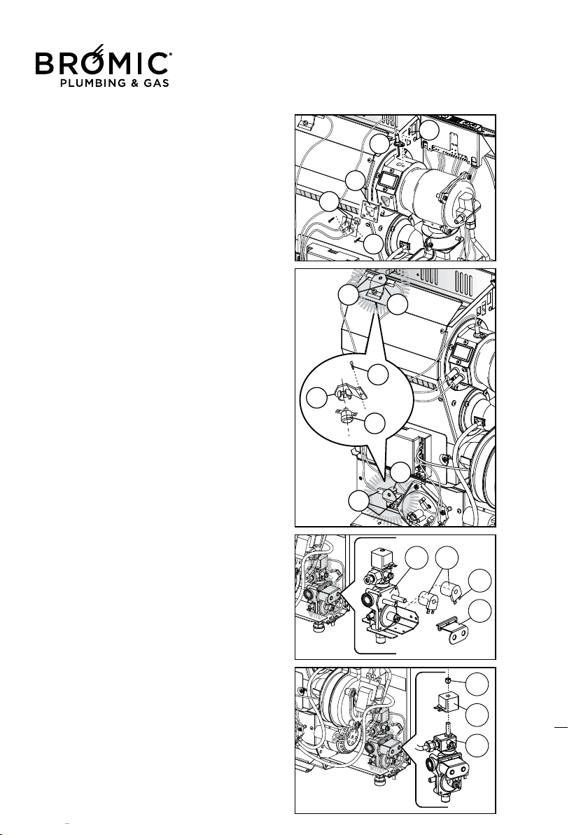
Electrodes replacement
Follow the indication to replace the electrode.
- The ignition electrode (1) and revelation (2) half to
be cleaned real carefully, after a period of time they
get fragile because of the work they which they do.
- Take off the high-tension cable
- Unscrew the screws (3 o 4) and extract the electro-
de group (1 o 2)
- Reassemble the electrode (1 o 2) with the reversed
sequence of the a
ssemblage replace the seal gasket
(5) be real careful at not damage the electrodes
ceramic insulator.
-Reconnect the cables on the processor control box
(P.C.B assy) (6).
Replacing the safety thermostat (manual resetting)
Follow the instructions below to remove and refit the
thermostat (3):
- remove the thermostat retention bracket (1) by loo-
sening the screw (2).
- disconnect the power connectors from the
Safety
thermostat (4).
- refit the thermostat unit in reverse fitting sequence.
The safety thermostat trips if the convection fan is
not working properly or anomalous overheating
occurs and/or the outflowing air temperature reaches
over 107°C, disengaging the burner, closing the gas
valve and stopping the appliance.
In case of part replacement (electronic boards, val-
ves, thermostats, pressure switches,
fans, etc.), only
use the Manufacturer's Original Spares.
Valve gas coil replacement
- Follow the indication to replace valve gas coil:
-Unscrew the screws that hold the stirrup (4) that
block the coil (1) at the valve body (2) and replace.
-Extract the fail-soft coil (1) taking it out real careful.
-Replace the new fail-soft coil (3) putting in the right
position
- 4 replace the flask (4) to stop the coil
.
Coil modulator replacement
- Follow the indication to replace coil modulator:
- remove the electrical connections.
- unscrew the nut (1) attachment that locks the reel
(2) the valve body (3) and remove it.
- emove the faulty coil (2), pulling it carefully.
- reinsert the new coil, taking care to position it cor-
rectly.
- replace the electrical connections.
Flued Indoor Gas Heater - Instruction Manual
28
July 2019 - V1
Replacing the gas valve
Follow the instructions below to remove and refit the
valve:
- remove the power connections.
- loosen the retention nut that secures the burner
pipe (1) to the valve body (2).
- loosen the retention nut that secures the mains gas
pipe (3) to the valve body.
- loosen the retention fork screw and remove it.
- remove the faulty valve by sliding off carefully.
- fit the new valve, being
careful to position this correctly.
- fit the power and gas connections back on.
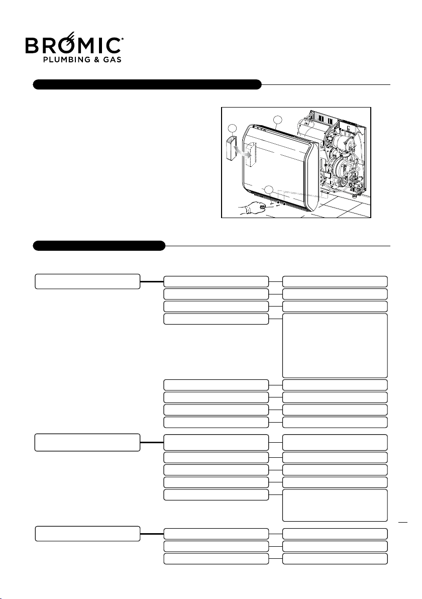
Pressure switch replacement
Follow the indication to replace the Pressure switch
- Extract the pressure switch (1) from support (2)
-Take off the tubes (3 & 4) and the electrical connec-
tors from the pressure switch.
- Unscrew the stirrup support fixing screw (2) separa-
ting the pressure switch from the frame.
-Reassemble t
he new pressure switch
-Insert the silicone tubes (3 & 4), also be real careful
when you reconnect the cables, if you are not sure of
what you are doing look at the electrical diagram.
Always remember, to use original spare parts.
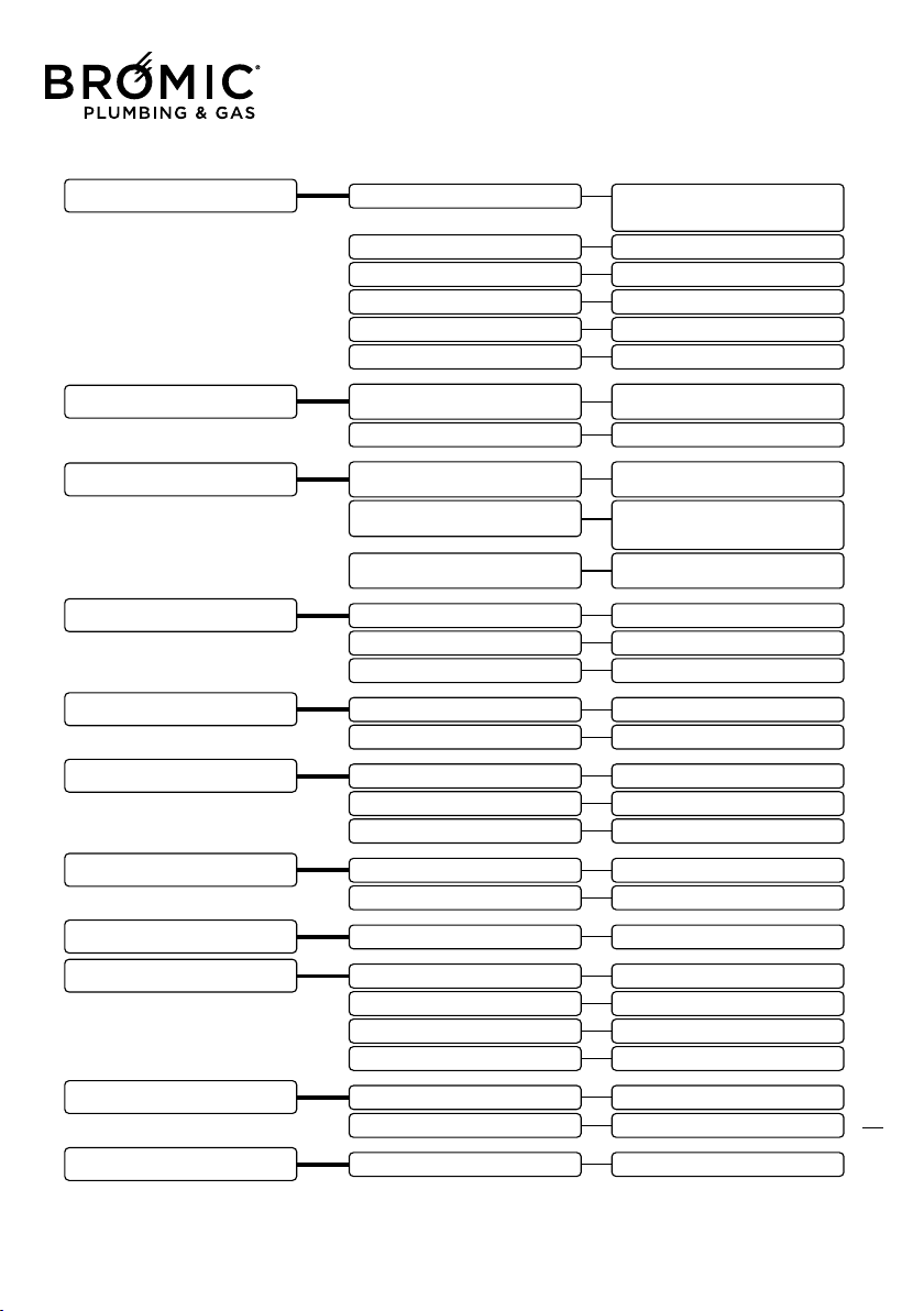
Replacing the condenser (model 50, 70 and 90 only)
Follow the instructions below to remove and refit the
fan condenser:
- take out the damaged condenser (1)
- replace the compo
nent part and fit it back, perfor-
ming removal operations in the opposite sequence.
29
CUSTOMER SERVICE
Flued Indoor Gas Heater - Instruction Manual
29
July 2019 - V1
30
CUSTOMER SERVICE
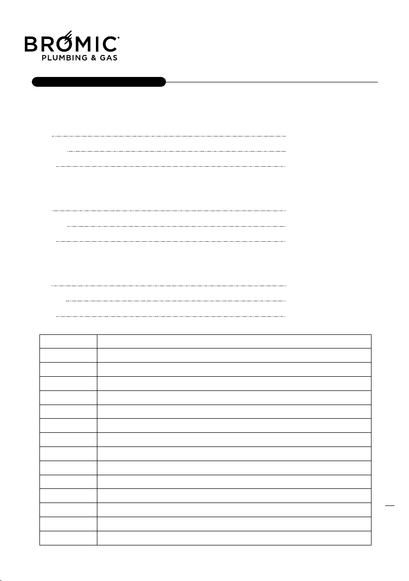
Disassembly cover
- Disassembly the casing;
- Remove the cup (3);
- Unscrew the screw (2);
- Remove the outside skirt (1) completely;
- To replace the skirt do the reversed sequence.
DISASSEMBLY & RIASSEMBLY OF THE CASING
EVENTUAL ANOMALY
Flued Indoor Gas Heater - Instruction Manual
30
July 2019 - V1
31
CUSTOMER SERVICE
Flued Indoor Gas Heater - Instruction Manual
31
July 2019 - V1
USEFUL INFORMATION
32
CUSTOMER SERVICE

Flued Indoor Gas Heater - Instruction Manual
32
July 2019 - V1
33
NOTE
NOTE
