
IMPORTANT MANUAL Do Not Throw Away
OWNER'S MANUAL
MODEL:
PD22H42STA
LAWN TRACTOR
,_k WARNING:
Read this Owner's Manual and follow allWarnings
and Safety Instructions. Failure to do so can result
in serious injury.
ALWAYS WEAR EYE PROTECTION DURING OPERATION
188781 Rev. 1 11.3.03 RD/MH
• Printed in U.S.A.
SAFETY RULES
SAFE OPERATION PRACTICES FOR RIDE.ON MOWERS
IMPORTANT" THIS CUTTING MACHINE IS CAPABLE OF AMPUTATING HANDS AND FEET AND THROWING OBJECTS. FAILURE
TO OBSERVE THE FOLLOWING SAFETY INSTRUCTIONS COULD RESULT IN SERIOUS INJURY OR DEATH.
I. GENERAL OPERATION
• Read, understand, and follow all instructions in the
manual and on the machine before starting.
• Only allow respensible adults, who are familiar with the
instructions, to operate the machine.
• Cleerthe area ofobjectssuch as rocks,toys,wire, etc.,
which could be picked up and thrown by the blade.
• Be sure the area is clear of other people before mow-
ing. Stop machine ifanyone enters the area.
• Never carry passengers.
• Do not mow in reverse unless absolutely necessary.
Always look down and behind before and while back-
ing.
• Be aware of the mower discharge direction and do not
point it at anyone. Do not operate the mower without
either the entire grass catcher or the guard in place.
• Slow down before turning.
• Never leave a running machine unattended. Always
turn off blades, set parking brake, stop engine, and
remove keys before dismounting.
• Turn off blades when not mowing.
• Stop engine before removing grass catcher or un-
clogging chute.
• Mow only in daylight or good artificial light.
• Do not operate the machine while under the influence
of alcohol or drugs.
• Watch for traffic when operating near or crossing road-
ways.
• Use extra care when loading or unloadingthe machine
into a trailer or truck.
• Data indicates thatoperators, age 60 years and above,
are involvedin a large percentage of riding mower-re-
lated injuries. These operators should evaluate their
ability to operate the dding mower safely enough to
protect themselves and others from serious injury.
• Keep machine free of grass, leaves or other debris
build-up which can touch hot exhaust / engine parts
and burn. Do not allowthe mower deckto plow leaves
or other debris which can cause build-up to occur.
Clean any oil or fuel spillage before operating or
storing the machine. Allow machine to cool before
storage.
II. SLOPE OPERATION
Slopes are a major factor related to loss-of-control and tipover
accidents, which can result in severe injury or death. All slopes
require extra caution. If you cannot back up the slope or ifyou
feel uneasy on it, do not mow it.
DO:
Mow up and down slopes, not across.
• Remove obstacles such as rocks,tree limbs, etc.
• Watch for holes, ruts,or bumps, Uneven terrain could
overturn the machine. Ta/Igrass can hide obstacles.
• Use slow speed. Choose a low gear so that you will
not have to stop or shift while on the slope.
Followthe manufacturer's recommendations for wheel
weights or counterweights to improve stability.
• Useextra carewithgrasscatchersorotherattachments.
These can change the stability ofthe machine.
Keep all movement on the slopes slow and gradual.
Do not make sudden changes in speed or direction.
• Avoid starting or stoppingon a slope. Iftires lose trac-
tion, disengage the bladesand proceed slowlystraight
down the slope.
2
DO NOT:
• Do not turn on slopes unless necessary, and then,
turn slowly and gradually downhill;if possible.
• Do not mow near drop-offs, ditches, or embankments.
The mower could suddenly tum over ifa wheel isover
the edge of a cliffor ditch, or ifan edge caves in.
• Do not mow on wet grass. Reduced traction could
cause sliding.
• Do not try to stabilizethe machine by puttingyourfoot
on the ground.
• Do not use grass catcher on steep slopes.
III, CHILDREN
Tragic accidents can occur ifthe operator is not alert to
the presence of children. Children are often attracted to
the machine and the mowing activity. Never assume that
children will remain where you last saw them.
• Keep children out of the mowing area and under the
watchful care of another responsible adult.
• Be alert and turn machine off if children enter the
area.
• Before and when backing, look behind and down for
small children.
• Never carry children.They mayfall offand be seriously
injured or interfere with safe machine operation.
• Never allow children to operate the machine.
• Useextrecare when apprcachingblindcorners, shrubs,
trees, or other objects that may obscure vision.
IV. SERVICE
• Use extra care in handling gasoline and other fuels.
They are flammable and vapors are explosive.
- Use only an approved container.
- Never remove gas cap or add fuel with the engine
running. Allow engine to cool before refueling. Do
not smoke.
- Never refuel the machine indoors.
- Never store the machine orfuelcontainer inside where
there is an open flame, such as a water heater.
• Never run a machine inside a closed area.
• Keep nuts and bolts, especially blade attachment bolts,
tight and keep equipment in good condition.
• Never tamper with safety devices. Check their proper
operation regularly.
Keep machine free of grass, leaves, or other debris
build-up. Clean oil or fuel spillage. Allow machine to
cool before storing.
• Stop and inspect the equipment ifyou strike an object.
Repair, if necessary, before restarting.
• Never make adjustments or repairs with the engine
running.
• Grass catcher components are subject to wear, dam-
age, and deterioration, which could expose moving
parts or allow objects to be thrown. Frequently check
components and replace with manufacturer's recom-
mended parts, when necessary.
• Mower blades aresharp and can cut. Wrapthe blade(s)
or wear gloves, and use extra caution when servicing
them.
• Check brake operation frequently. Adjust and service
as required.
SAFETY RULES
SAFE OPERATION PRACTICES FOR RIDE-ON MOWERS
IMPORTANT: THIS CUTTING MACHINE IS CAPABLE OF AMPUTATING HANDS AND FEET AND THROWING OBJECTS. FAILURE
TO OBSERVE THE FOLLOWING SAFETY INSTRUCTIONS COULD RESULT IN SERIOUS INJURY OR DEATH.
• Be surethe area isclear of other people before mowing.Stop
machine if anyone enters the area.
Never carry passengers or children even with the blades
off.
• Do not mow in reverse unless absolutely necessary. Always
look down and behind before and while backing.
Never carrychildren.They mayfalloft and be sedously injured
or interfere with safe machine operation.
Keep children out of the mowingarea and under the watchful
care of another responsible adult.
• Be alert and turn machine off if children enter the area.
Before and when backing, look behind and down for small
children.
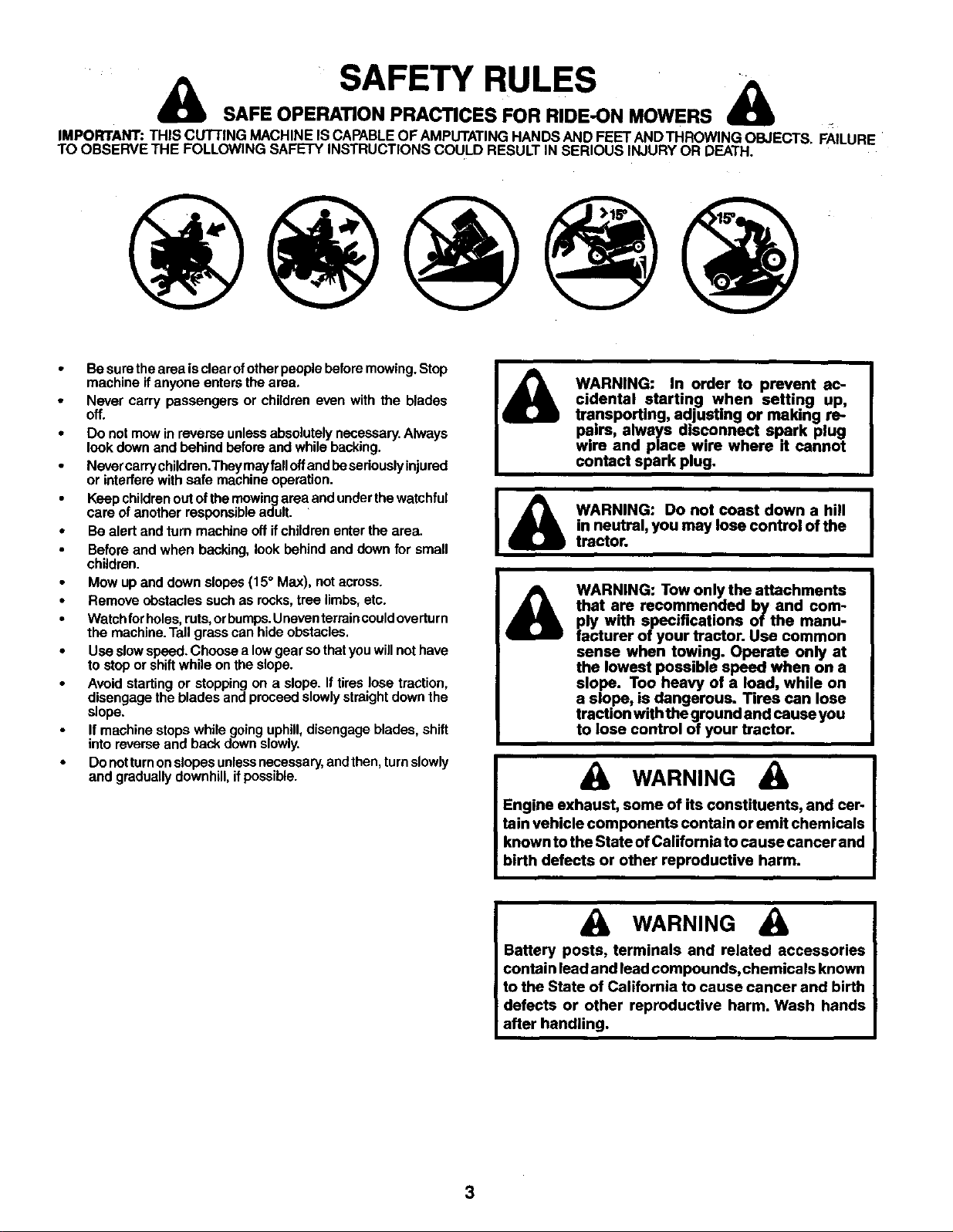
Mow up and down slopes (15 ° Max), not across.
• Remove obstacles such as rocks,tree limbs, etc.
• Watch forholes,ruts, orbumps. Uneven terraincould overturn
the machine. Tall grass can hide obstacles.
• Usa slow speed. Choose a low gear so that you will not have
to stop or shiftwhile on the slope.
Avoid starting or stopping on a slope. If tires lose traction,
disengage the blades and proceed slowly straight down the
slope.
If machine stops while going uphill,disengage blades, shift
into reverse and back down slowly.
• Do not turnonslopes unlessnecessary, and then, turnslowly
and gradually downhill, if possible.
WARNING: In order to prevent ac-
cidental starting when setting up,
transporting, adjusting or making re-
pairs, always disconnect spark plug
wire and place wire where it cannot
contact spark plug.
I
WARNING: Do not coast down a hill |
in neutral, you may lose control of the
I
tractor.
WARNING
Engine exhaust, some of its constituents, and car-
tain vehicle components contain or emit chemicals
known to the State of California tocause cancer and
birth defects or other reproductive harm.
WARNING
Battery posts, terminals and related accessories
contain lead and lead compounds, chemicals known
to the State of California to cause cancer and birth
defects or other reproductive harm. Wash hands
after handling.
3
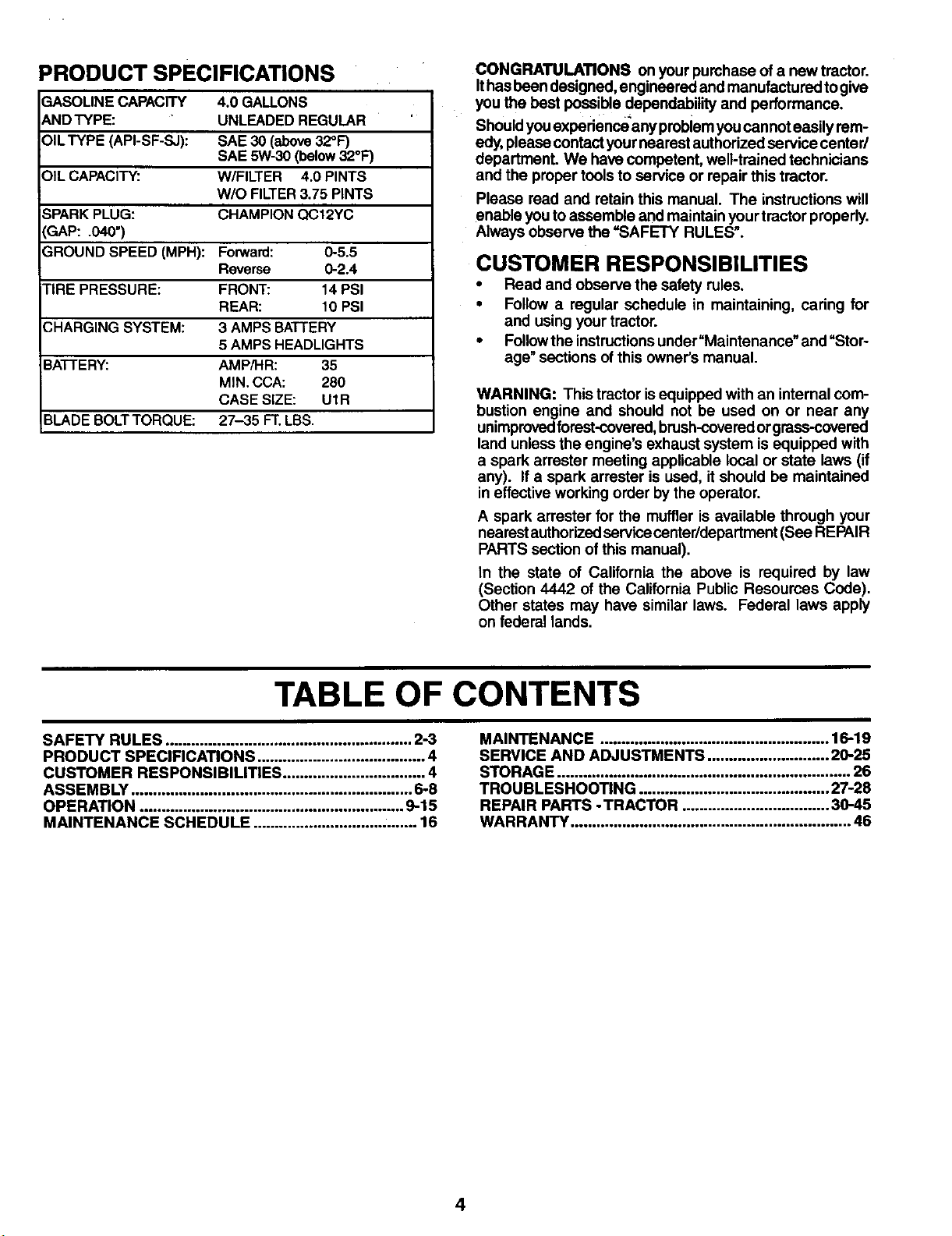
PRODUCT SPECIFICATIONS
GASOLINE CAPACITY 4.0 GALLONS
ANDTYPE: UNLEADED REGULAR
OILTYPE (API-SF-SJ): SAE 30 (above32°F)
SAE 5W-30 (below32°F)
OIL CAPACITY: W/FILTER 4.0 PINTS
W/O FILTER3.75 PINTS
SPARKPLUG: CHAMPION QC12YC
3AP: .040=)
GROUND SPEED (MPH): Forward: 0-5.5
Reverse 0-2.4
FIRE PRESSURE: FRONT: 14 PSI
REAR: 10 PSI
3HARGING SYSTEM: 3 AMPS BATTERY
5 AMPS HEADLIGHTS
BATTERY: AMP/HR: 35
MIN. CCA: 280
CASE SIZE: U1R
BLADE BOLTTORQUE: 27-35 FT.LBS.
CONGRATULATIONS on your purchase ofa new tractor.
Ithasbeen designed, engineered and manufactured togive
you the best possible dependability and performance.
Shouldyouexperience any problemyoucannot easily rem-
edy, please contact your nearest authorized service center/
department. We havecompetent, well-trained technicians
and the proper tools to service or repair this tractor.
Please read and retain this manual. The instructions will
enable you to assemble and maintainyour tractor properly.
Always observe the =SAFETY RULES".
CUSTOMER RESPONSIBILITIES
• Read and observe the safety rules.
• Follow a regular schedule in maintaining, caring for
and using your tractor.
• Followthe instructionsunder=Maintenance" and =Stor-
age" sections of this owner's manual.
WARNING: This tractor isequipped with an internal com-
bustion engine and should not be used on or near any
unimprovedforast-covered, brush-coveredor grass-covered
land unless the engine's exhaust system isequipped with
a spark arrester meeting applicable local or state laws (if
any). If a spark arrester is used, it should be maintained
in effective working order by the operator.
A spark arrester for the muffler is available through your
nearest authorizedservicecenter/department (See REPAIR
PARTS section ofthis manual).
In the state of California the above is required by law
(Section 4442 of the California Public Resources Code).
Other states may have similar laws. Federal laws apply
on federal lands.
TABLE OF CONTENTS
SAFETY RULES ......................................................... 2-3
PRODUCT SPECIRCATIONS ....................................... 4
CUSTOMER RESPONSIBILITIES ................................. 4
ASSEMBLY ................................................................. 6-8
OPERATION ............................................................. 9-15
MAINTENANCE SCHEDULE ...................................... 16
MAINTENANCE ..................................................... 16.-19
SERVICE AND ADJUSTMENTS ............................ 29-25
STORAGE .................................................................... 26
TROUBLESHOOTING ............................................ 27-28
REPAIR PARTS - TRACTOR .................................. 30-45
WARRANTY ................................................................. 46
4
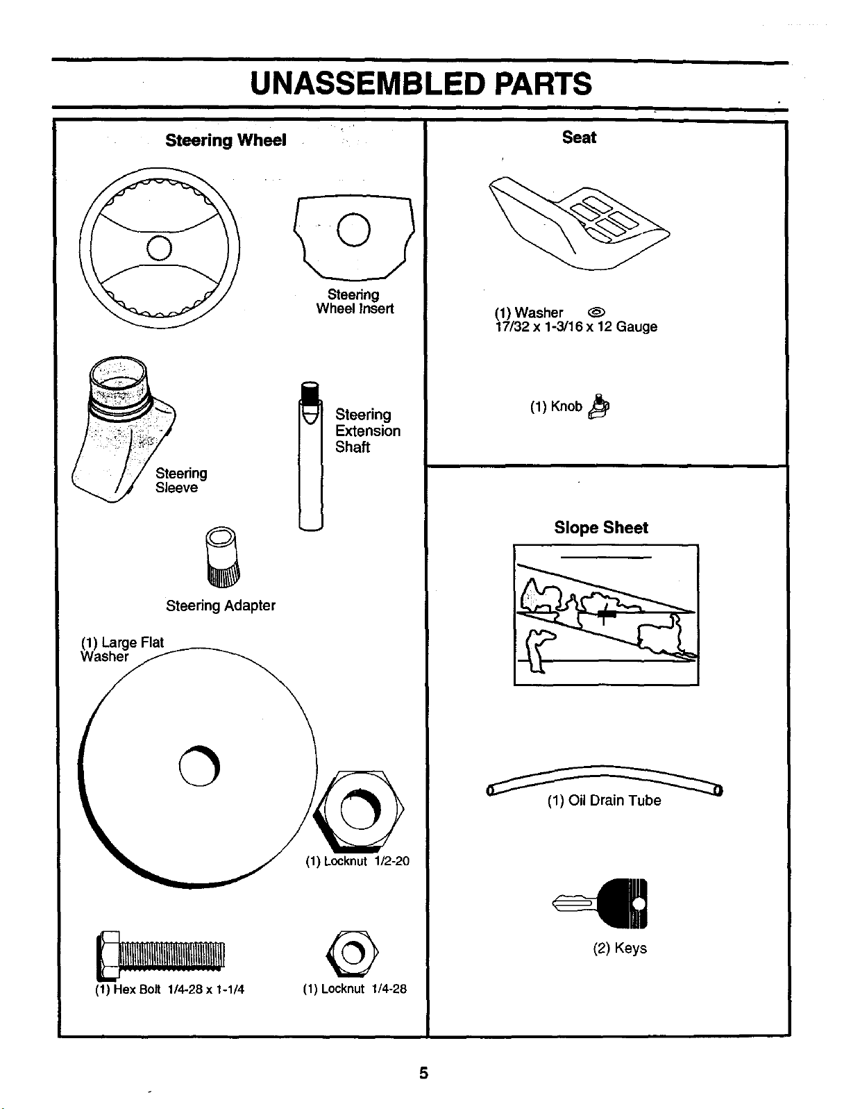
UNASSEMBLED PARTS
Steering Wheel
Steering
Sleeve
Steering Adapter
(1) Large Flat
Washer
O
(1) Hex Bolt 1/4-28 x 1-1/4
Steering
Wheel Insert
Steering
Extension
Shaft
(1) Locknut 1/2-20
@
(1) Locknut 1/4-28
Seat
(1) Washer
17/32 x 1-3/16 x 12 Gauge
(1) Knob
Slope Sheet
(1) Oil Drain Tube
(2) Keys
5
ASSEMBLY
Your new tractor has been assembled at the factory with exception ofthose parts left unassembled for shipping purposes.
To ensure safe and proper operation of your tractor all parts and hardware you assemble mustbe tightened securely. Use
the correct tools as necessary to insure proper tightness.
TOOLS REQUIRED FOR ASSEMBLY
A socket wrench set will make assembly easier. Standard
wrench sizes are listed.
Utility knife Pliers
(1) 3/4" wrenches Tire pressure gauge
(2) 7/16" wrenches Utility knife
When rightorlefthand ismentionedinthismanual, itmeans
when you are in the operating position (seated behind the
steering wheel).
TO REMOVE TRACTOR FROM CAR-
TON
UNPACK CARTON
• Remove all accessible loose parts and parts cartons
from carton.
• Cut along dotted lines on all four panels of carton.
Remove end panels and lay side panels flat.
• Check for any additional loose parts or cartons and
remove.
BEFORE REMOVING TRACTOR FROM
SKID
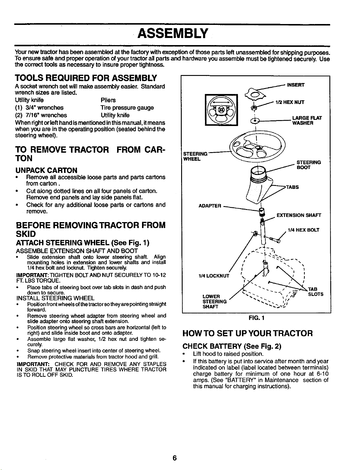
A'rrACH STEERING WHEEL (See Fig. 1)
ASSEMBLE EXTENSION SHAFT AND BOOT
.
Slide extertsion shaft onto lower steering shaft. Align
mounting holes in extension and lower shafts and install
1/4 hex bolt and Iooknut. Tighten securely.
IMPORTANT: TIGHTEN BOLT AND NUT SECURELY TO 10-12
FT. LBS TORQUE.
Place tabs of steering boot over tab slots in dash end push
down to secure.
INSTALL STEERING WHEEL
• Position front wheels ofthetractor so theyare pointing straight
forward.
• Remove steering wheel adapter from steering wheel and
slide adapter onto steering shaft extension.
Position steering wheel so cross bars are horizontal (left to
right) and slide inside boot and onto adapter.
Assemble large flat washer, 1/2 hex nut and tighten se-
curely.
Snap steering wheel insert into center of steering wheel.
• Remove protective materials from tractor hood and grill.
IMPORTANT: CHECK FOR AND REMOVE ANY STAPLES
IN SKID THAT MAY PUNCTURE TIRES WHERE TRACTOR
IS TO ROLL OFF SKID.
__I_H NSERT
EX NUT
.. LARGE FLAT
WASHER
ADAPTER
,I_ EXTENSION SHAFT
FIG, 1
HOW TO SET UP YOUR TRACTOR
CHECK BATTERY (See Fig. 2)
• Lift hood to raised position.
• Ifthis battery is put intoservice after month and year
indicated on label (label located between terminals)
charge battery for minimum of one hour at 6-10
amps. (See "BATFERY" in Maintenance section of
this manual for charging instructions).
6
ASSEMBLY
• ~_.. i
., -~~1
i
,J
FIG. 2
HOW TO SET UP YOUR TRACTOR
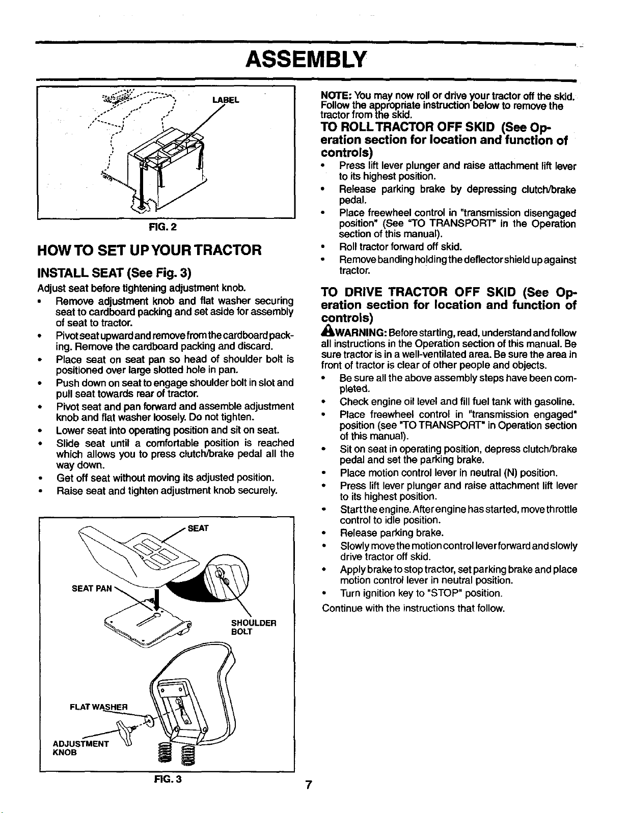
INSTALL SEAT (See Fig. 3)
Adjust seat before tightening adjustment knob.
• Remove adjustment knob and fiat washer securing
seat to cardboard packing and set aside for assembly
of seat to tractor.
• Pivotseat upwardand removefromthecardboard pack-
ing. Remove the cardboard packing and discard.
• Place seat on seat pan so head of shoulder bolt is
positioned over large slotted hole in pan.
• Push down on seat toengage shoulder boltin slot and
pull seat towards rear of tractor.
• Pivot seat and pan forward and assemble adjustment
knob and flat washer loosely.Do not tighten.
• Lower seat into operating position and sit on seat.
• Slide seat until a comfortable position is reached
which allows you to press clutch/brake pedal all the
way down.
• Get off seat without moving itsadjusted position.
• Raise seat and tighten adjustment knob securely.
SHOULDER
BOLT
ADJUSTMENT
KNOB
NOTE: You may now rollor drive your tractoroff the sldd.
Followthe appropriate instruction below to remove the
tractor from the skid.
TO ROLLTRACTOR OFF SKID (See Op-
eration section for location and function of
controls)
• Press lift lever plunger and raise attachment lift lever
to its highest position.
• Release parking brake by depressing clutch/brake
pedal.
• Place freewheel control in "transmissiondisengaged
position" (See =TO TRANSPORT" in the Operation
section of this manual).
• Roll tractorforward off skid.
• Remove bandingholdingthedeflectorshield upagainst
tractor.
TO DRIVE TRACTOR OFF SKID (See Op-
eration section for location and function of
controls)
_WARNING: Beforestarting, read, understandand follow
all instructionsinthe Operation section ofthis manual. Be
sure tractor isin a well-ventilated area. Be sure the area in
front of tractor is clear of other people and objects.
• Be sure all the above assembly steps have been corn-
plated.
• Check engine oil level and fill fuel tank with gasoline.
• Place freewheel control in "transmission engaged"
position (see "TO TRANSPORT" in Operation section
ofthis manual).
• Siton seat in operating position,depress clutch/brake
pedal and set the parking brake.
• Place motion control lever in neutral (N) position.
• Press lift lever plunger and raise attachment lift lever
to its highest position.
• Startthe engine.After engine hasstarted, movethrottle
controlto idle position.
• Release parking brake.
• Slowlymovethemotioncontrolleverforward and slowly
drive tractor off skid.
• Apply braketo stoptractor, set parking brake and place
motion control lever in neutral position.
• Turn ignitionkey to "STOP" position.
Continue with the instructionsthat follow.
RG. 3
7
ASSEMBLY
CHECK BRAKE SYSTEM
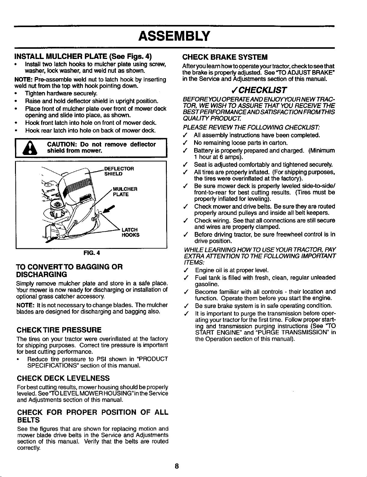
INSTALL MULCHER PLATE (See Figs. 4)
• Install two latch hooks to muicher plate using screw,
washer, look washer, and weld nut as shown.
NOTE: Pro-assemble weld nut to latch hook by inserting
weld nut from the top with hook pointing down.
• Tighten hardware securely.
• Raise and hold deflector shield in upright position.
• Place front of mulcher plate over front of mower deck
opening and slide into place, as shown.
• Hook front latch into hole on front of mower deck.
• Hook rear latch into hole on back of mower deck.
CAUTION: Do not remove deflectorshield from mower.
DEFLECTOR
SHIELD
PLATE
HOOKS
FIG. 4
TO CONVERTTO BAGGING OR
DISCHARGING
Simply remove mulcher plate and store in a safe place.
Yourmower is now ready for discharging or installation of
optional grass catcher accessory.
NOTE: It isnot necessary to change blades. The mulcher
blades are designed for discharging and bagging also.
CHECKTIRE PRESSURE
The tires on your tractor were overinflated at the factory
for shipping purposes. Correct tire pressure is important
for best cutting performance.
Reduce tire pressure to PSI shown in "PRODUCT
SPECIFICATIONS" section ofthis manual.
CHECK DECK LEVELNESS
Forbestcutting results, mower housingshould be properly
leveled. See "TO LEVEL MOWER HOUSING" intheService
and Adjustments section of this manual.
CHECK FOR PROPER POSITION OF ALL
BELTS
See the figures that are shown for replacing motion and
mower blade drive belts in the Service and Adjustments
section of this manual. Verify that the belts are routed
correctly.
After you learn howtooperate yourtractor,checktosee that
the brake isproperly adjusted. See "TO ADJUST BRAKE"
in the Service and Adjustments section of this manual.
,/CHECKLIST
BEFORE YOU OPERATE AND ENJOY YOUR NEW TRAC-
TOR, WE WISH TO ASSURE THAT YOU RECEIVE THE
BEST PERFORMANCEAND SATISFACTION FROMTHIS
QUALITY PRODUCT.
PLEASE REVIEW THE FOLLOWING CHECKLIST."
,/ All assembly instructions have been completed.
,/ No remaining loose parts in carton.
/ Battery is propedy prepared and charged. (Minimum
1 hour at 6 amps).
/ Seat is adjusted comfortably and tightened securely.
/ All tires are properly inflated. (For shipping purposes,
the tires were overinflated at the factory).
,,I Be sure mower deck is properly leveled side-to-side/
front-to-rear for best cutting results. (Tires must be
properly inflated for leveling).
,/ Check mower and drivebelts° Besuretheyarereuted
properly around pulleys and inside all belt keepers.
,/ Check wiring. See that all connections are stillsecure
and wires are properly clamped.
,/ Before driving tractor, be sure freewheel control is in
drive position.
WHILE LEARNING HOW TO USE YOUR TRACTOR, PAY
EXTRA ATTENTION TO THE FOLLOWING IMPORTANT
ITEMS:
,/ Engine oil isat proper level.
,/ Fuel tank isfilled with fresh, clean, regular unleaded
gasoline.
,/ Become familiar with all controls - their location and
function. Operate them before you start the engine.
,/ Be sure brake system is in safe operating condition.
•/ It is important to purge the transmission before oper-
ating your tractorfor the first time. Followproper start-
ing and transmission purging instructions (See "TO
START ENGINE" and "PURGE TRANSMISSION" in
the Operation section of this manual).
8
• *,f •
OPERATION
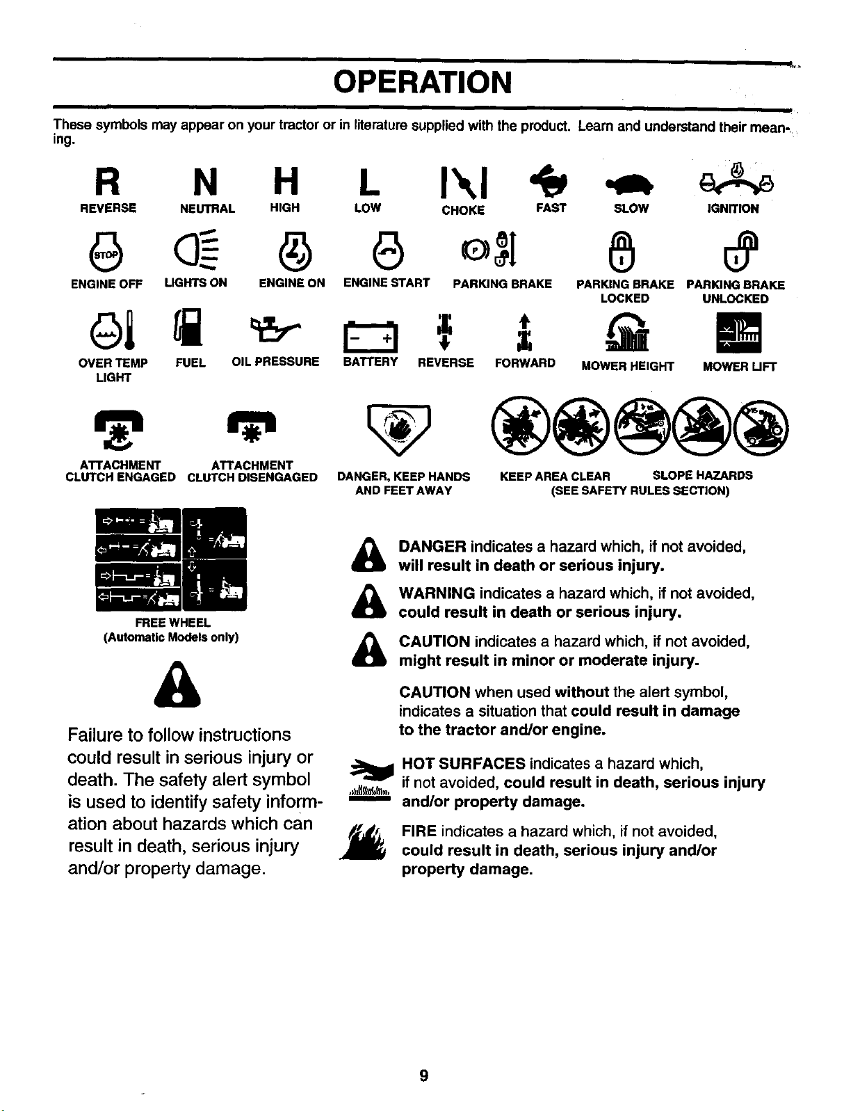
These symbols may appear on your tractor or in literature supplied with the product. Learn and understand their mean-_
ing.
R N H L I\1
REVERSE NEUTRAL HIGH LOW CHOKE FAST SLOW IGNITION
ENGINE OFF LIGHTS ON ENGINE ON ENGINE START PARKING BRAKE PARKING BRAKE PARKING BRAKE
LOCKED UNLOCKED
OVER TEMP FUEL OIL PRESSURE BATTERY REVERSE FORWARD
LIGHT
MOWER HEIGHT MOWER UFT
ATTACHMENT ATTACHMENT
CLUTCH ENGAGED CLUTCH DISENGAGED
FREE WHEEL
(Automatic Models only)
DANGER, KEEP HANDS
AND FEET AWAY
KEEP AREA CLEAR SLOPE HAZARDS
(SEE SAFETY RULES SECTION)
&
Failure to follow instructions
could result in serious injury or
death. The safety alert symbol
is used to identify safety inform-
ation about hazards which can
result in death, serious injury
and/or property damage.
&
&
&
DANGER indicates a hazard which, if not avoided,
will result in death or serious injury.
WARNING indicates a hazard which, if not avoided,
could result in death or serious injury,
CAUTION indicates a hazard which, if not avoided,
might result in minor or moderate injury.
CAUTION when used without the alert symbol,
indicates a situation that could result in damage
to the tractor and/or engine.
HOT SURFACES indicates a hazard which,
if not avoided, could result in death, serious injury
and/or property damage.
J_ FIRE indicates a hazard which, if not avoided,
could result in death, serious injury and/or
property damage•
9
OPERATION
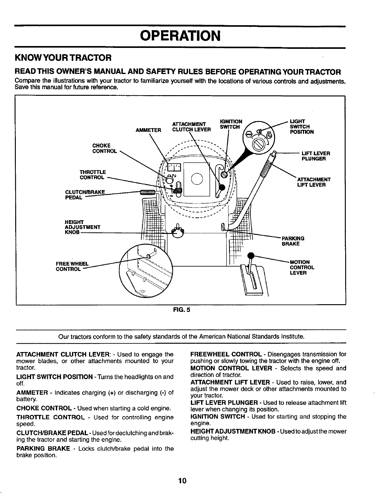
KNOW YOUR TRACTOR
READ THIS OWNER'S MANUAL AND SAFETY RULES BEFORE OPERATING YOUR TRACTOR
Compare the illustrations with your tractor to familiarize yourself with the locations of various controls and adjustments.
Save this manual for future reference.
IGNmON
ATTACHMENT SWITCH swrrcH
AMMETER CLUTCH LEVER PosmoN
CHOKE "-
PEDAL
THROTTLE
_'VER
PLUNGER
AnACHMENT
UFT LEVER
HEIGHT
ADJUSTMENT
KNOB
"PARING
BRAKE
FREE WHEEL - MOTION
CONTROL
CONTROL LEVER
FIG. 5
Our tractors conform to the safety standards ofthe American National Standards Institute.
ATTACHMENT CLUTCH LEVER: - Used to engage the
mower blades, or other attachments mounted to your
tractor.
LIGHT SWITCH POSITION -Turns the headlights on and
off.
AMMETER - Indicates charging (+) or discharging (-) of
battery.
CHOKE CONTROL - Used when starting a cold engine.
THRO'n'LE CONTROL - Used for controlling engine
speed.
CLUTCH/BRAKE PEDAL- Used for declutchingand brak-
ing the tractor and starting the engine.
PARKING BRAKE - Locks clutch/brake pedal into the
brake position.
FREEWHEEL CONTROL - Disengages transmission for
pushing or slowly towing the tractor with the engine off.
MOTION CONTROL LEVER - Selects the speed and
direction of tractor.
ATTACHMENT LIFT LEVER - Used to raise, lower, and
adjust the mower deck or other attachments mounted to
your tractor.
LIFT LEVER PLUNGER - Used to release attachment lift
lever when changing its position.
IGNITION SWITCH - Used for starting and stopping the
engine.
HEIGHT ADJUSTMENT KNOB - Used to adjustthemower
cutting height.
10
OPERATION
The operation of any tractor can result In foreign objects thrown into the ayes, which can I
result in severe eye damage. Always wear safety glasses or eye shields while operating
I
your tractor or performing any adjustments or repairs. We recommend a wide vision safety
mask over spectacles or standard safety glasses.
HOW TO USE YOUR TRACTOR
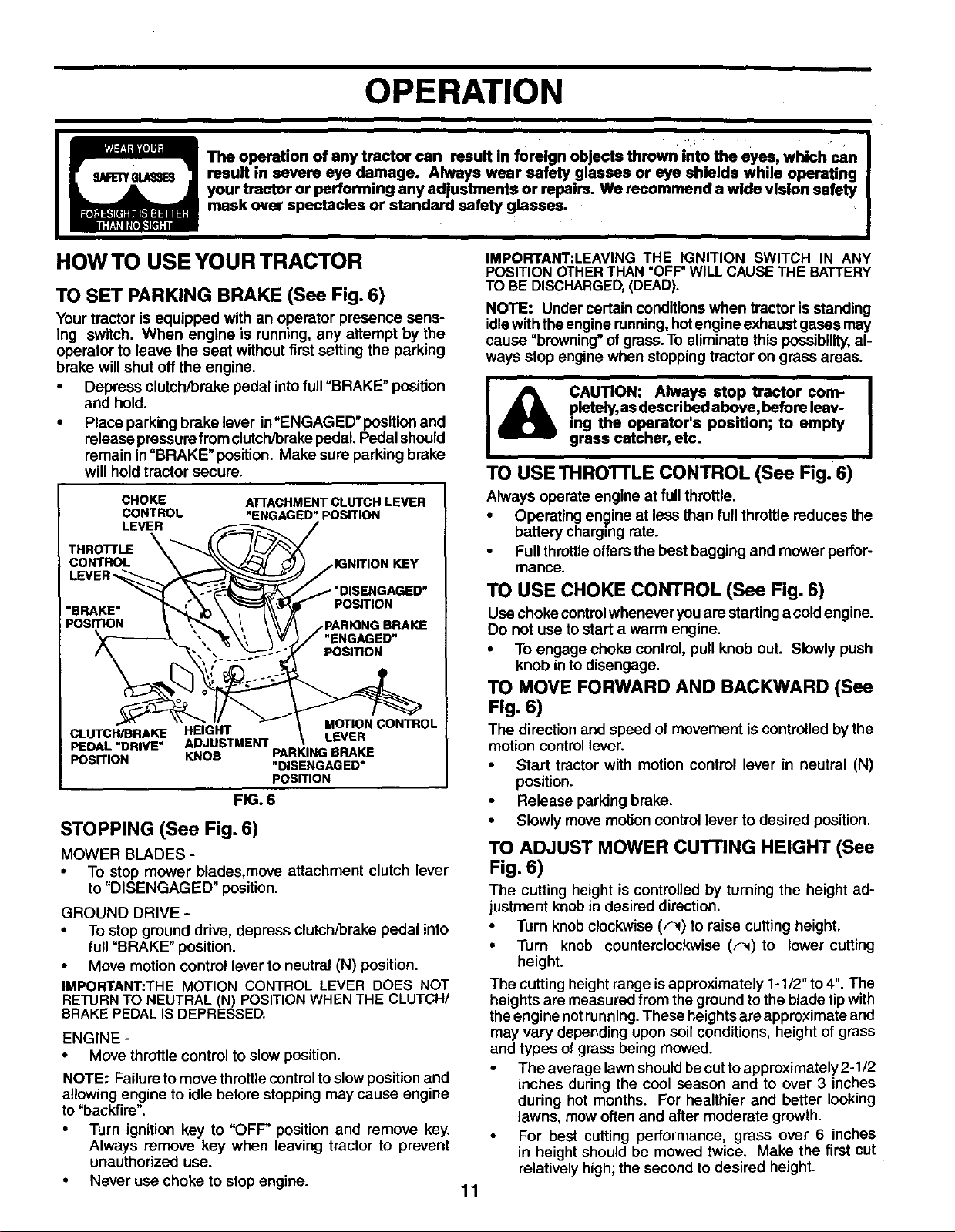
TO SET PARKING BRAKE (See Fig. 6)
Your tractor is equipped with an operator presence sens-
ing switch. When engine is running, any attempt by the
operator to leave the seat without first setting the parking
brake willshut off the engine.
• Depress clutch/brake pedal into full"BRAKE" position
and hold.
• Place parking brake lever in"ENGAGED" position and
release pressure from clutch/brakepedal. Pedal should
remain in=BRAKE" position. Make sure parking brake
will hold tractor secure.
CHOKE
CONTROL
LEVER
TNRO LE
CONTROL \ _-_"_ C
LEVER _
"BRAKE" '
CLUTCH/BRAKE HEIGHT
PEDAL "DRIVE" ADJUSTMENT
PosrrlON KNOB
ATrACHMENT CLUTCH LEVER
"ENGAGED" pOSITION
/
jlGNITION KEY
/ "DISENGAGED"
POSITION
j PARKING BRAKE
"ENGAGED
POSITION
MOTION CONTROL
LEVER
PARKINGBRAKE
"DISENGAGED"
POSITION
FIG. 6
STOPPING (See Fig. 6)
MOWER BLADES -
• To stop mower blades, move attachment clutch lever
to "DISENGAGED" position.
GROUND DRIVE -
• To stop ground drive, depress clutch/brake pedal into
full =BRAKE" position.
Move motion control lever to neutral (N) position.
IMPORTANT:THE MOTION CONTROL LEVER DOES NOT
RETURNTO NEUTRAL (N) POSITION WHEN THE CLUTCH/
BRAKE PEDALIS DEPRESSED.
ENGINE -
• Move throttle control to slow position.
NOTE: Failureto move throttle controltoslow position and
allowing engine to idle before stopping may cause engine
to "backfire".
• Turn ignition key to "OFF" position and remove key.
Always remove key when leaving tractor to prevent
unauthorized use.
• Never use choke to stop engine.
11
IMPORTANT:LEAVING THE IGNITION SWITCH IN ANY
POSITION OTHERTHAN "OFF"WILL CAUSETHE BATTERY
TO BE DISCHARGED,(DEAD).
NOTE: Under certain conditions when tractor is standing
idlewith theengine running,hot engine exhaust gases may
cause "browning" of grass.To eliminate this possibility, al-
ways stop engine when stopping tractor on grass areas.
I _lllb CAUTION: Always stop tractor corn- I
pletely, as described above, before leav-
ing the operator's position; to empty
grass catcher, etc.
TO USE THROI-FLE CONTROL (See Fig. 6)
Always operate engine at fullthrottle.
• Operating engine at less than full throttle reduces the
battery charging rate.
• Full throttleoffers the best bagging and mower perfor-
mance.
TO USE CHOKE CONTROL (See Fig. 6)
Usechoke controlwhenever youare startinga coldengine.
Do not use to start a warm engine.
• To engage choke control, pull knob out. Slowly push
knob in to disengage.
TO MOVE FORWARD AND BACKWARD (See
Fig. 6)
The direction and speed of movement iscontrolled bythe
motion controllever.
• Start tractor with motion control lever in neutral (N)
position.
• Release parking brake.
• Slowly move motion controllever to desired position.
TO ADJUST MOWER CUTTING HEIGHT (See
Fig. 6)
The cutting height is controlled by turning the height ad-
justment knob in desired direction.
• Turn knobclockwise (F_) to raise cutting height.
• Turn knob counterclockwise (,.-_)to lower cutting
height.
The cutting height range is approximately 1-1/2" to 4". The
heights are measured from the ground tothe blade tip with
the engine notrunning.These heightsare approximate and
may vary depending upon soil conditions, height of grass
and types of grass being mowed.
• The average lawn shouldbe cuttoapproximately 2-1/2
inches during the cool season and to over 3 inches
during hot months. For healthier and better looking
lawns, mow often and after moderate growth.
For best cutting performance, grass over 6 inches
in height should be mowed twice. Make the first cut
relatively high;the second to desired height.
OPERATION
"ENGAGED" POSITION
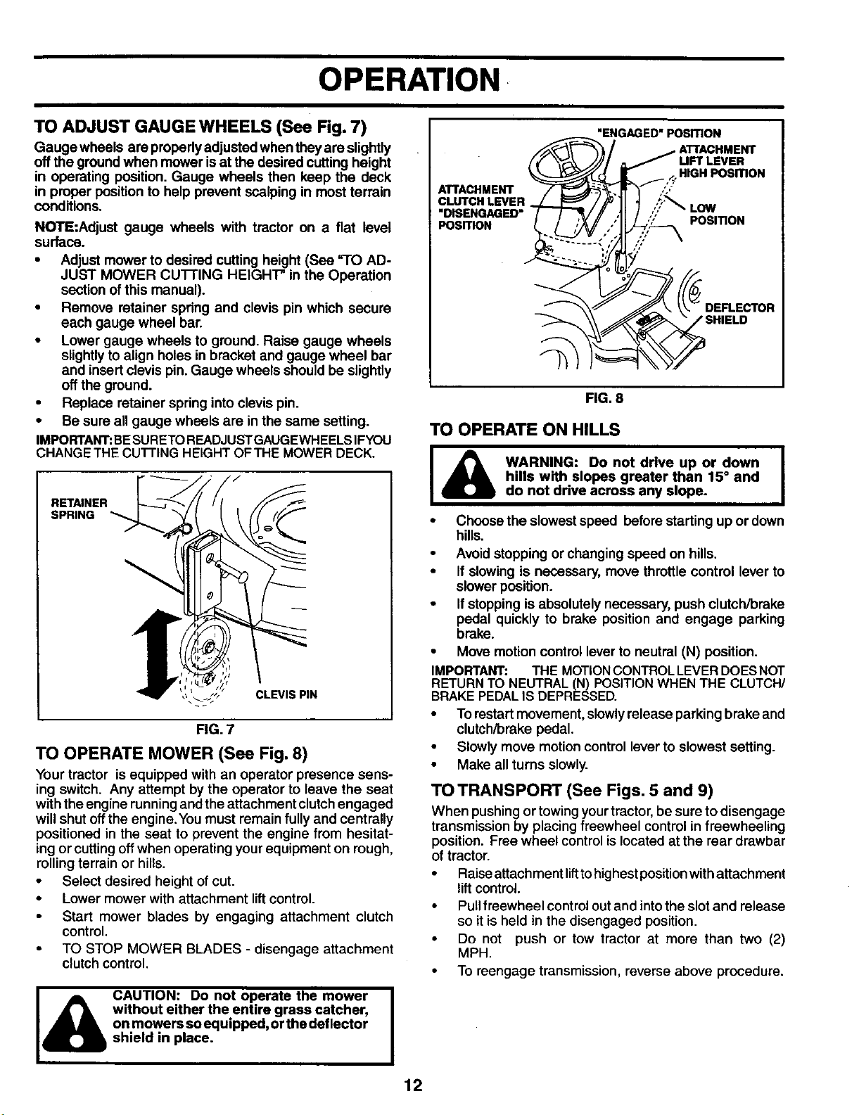
TO ADJUST GAUGE WHEELS (See Fig. 7)
Gauge wheels are properly adjusted when they are slightly
off the ground when mower isat the desired cutting height
in operating position, Gauge wheels then keep the deck
in proper position to help prevent scalping in most terrain
conditions.
NOTE:Adjust gauge wheels with tractor on a flat level
surface.
• Adjust mower to desired cutting height (See "1O AD-
JUST MOWER CUI-I'ING HEIGHI" in the Operation
section of this manual).
• Remove retainer spring and clevis pin which secure
each gauge wheel bar.
• Lower gauge wheels to ground. Raise gauge wheels
slightlyto align holes in bracket and gauge wheel bar
and insert clevis pin. Gauge wheels should be slightly
off the ground.
• Replace retainer spring intoclevis pin.
• Be sure all gauge wheels are in the same setting.
IMPORTANT:BESURETOREADJUSTGAUGEWHEELSIFYOU
CHANGE THE CUTTING HEIGHT OFTHE MOWER DECK.
RETAINER
SPRING
FIG. 7
TO OPERATE MOWER (See Fig. 8)
Your tractor is equipped with an operator presence sens-
ing switch. Any attempt bythe operator to leave the seat
with the engine runningand the attachment clutchengaged
will shut offthe engine. Youmust remain fully and centrally
positioned in the seat to prevent the engine from hesitat-
ing or cutting offwhen operating your equipment on rough,
rollingterrain or hills.
• Select desired height ofcut.
• Lower mower with attachment liftcontrol.
Start mower blades by engaging attachment clutch
control.
• TO STOP MOWER BLADES - disengage attachment
clutch control.
_ CAUTION: Do not operate the mower |
• • without either the entire grass catcher,
I
on mowers soequipped,or the deflector
O shield in place.
UFT LEVER
<,HIGH POSITION
ATTACHMENT .;.-
CLUTCH LEVER . "!'_ LOW
DISENGAGED
POSmON POSITION
FIG. 8
TO OPERATE ON HILLS
_lh WARNING: Do not drive up or down I
I
hills with slopes greater than 15° and
I
do not drive across any slope.
• Choose the slowest speed before starting up or down
hills.
• Avoid stopping or changing speed on hills.
• If slowing is necessary, move throttle control lever to
slower position.
• Ifstopping is absolutely necessary, push clutch/brake
pedal quickly to brake position and engage parking
brake.
• Move motion control lever to neutral (N) position.
IMPORTANT: THE MOTIONCONTROLLEVERDOESNOT
RETURN TO NEUTRAL (N) POSITIONWHEN THE CLUTCH/
BRAKE PEDALIS DEPRESSED.
• To restart movement, slowlyrelease parking brake and
clutch/brake pedal.
• Slowly move motion control lever to slowest setting.
• Make all turns slowly.
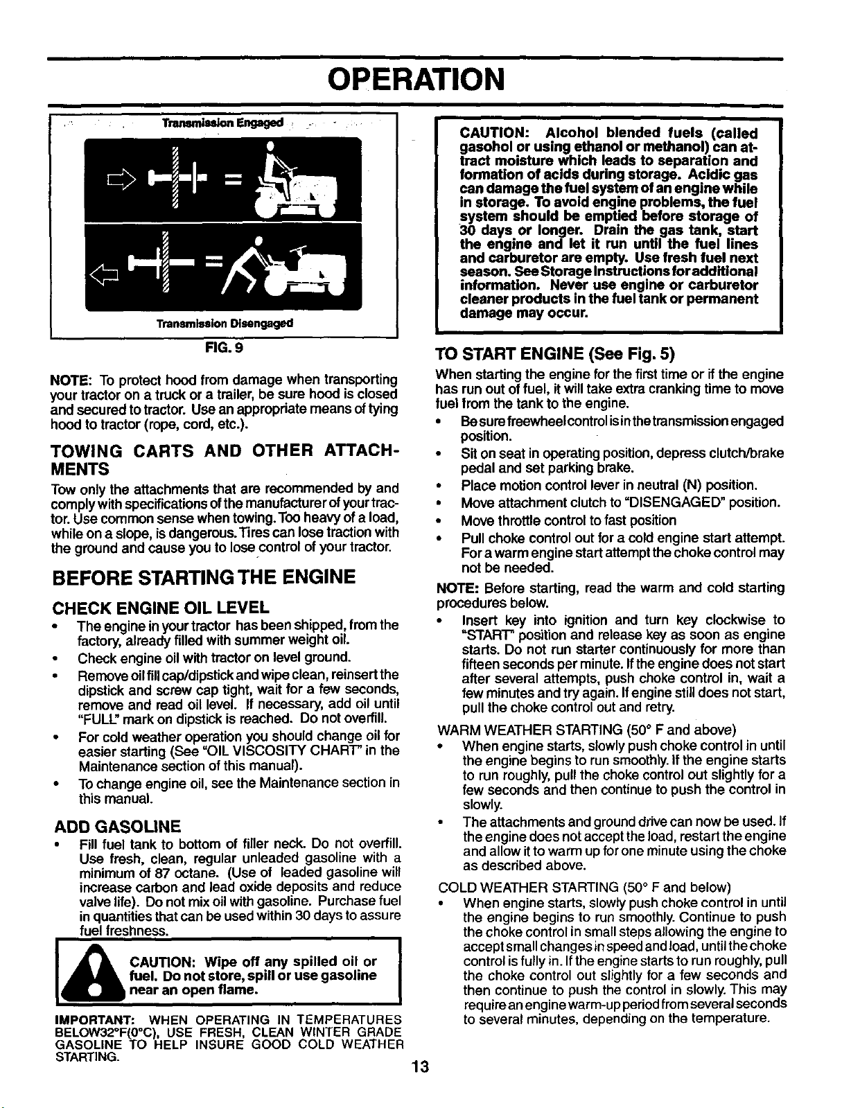
TO TRANSPORT (See Figs. 5 and 9)
When pushingor towing yourtractor,be sure todisengage
transmission by placing freewheel control in freewheeling
position. Free wheel controlis locatedat the rear drawbar
of tractor.
• Raise attachment lifttohighestpositionwith attachment
lift control.
• Pullfreewheel controlout and intothe slot and release
so it is held in the disengaged position.
• Do not push or tow tractor at more than two (2)
MPH.
• To reengage transmission, reverse above procedure.
12
OPERATION
_ Engaged . -
Transmission Disengaged
RG. 9
NOTE: To protect hood from damage when transperting
your tractor on a truck or a trailer, be sure hood isclosed
and secured totractor. Use an appropriate means oftying
hood to tractor (rope, cord, etc.).
TOWING CARTS AND OTHER ATTACH-
MENTS
Tow only the attachments that are recommended by and
comply with specificationsofthe manufacturer ofyourtrac-
tor.Use common sense when towing.Too heavy of a load,
while on a slope, isdangerous.Tires can losetraction with
the ground and cause you to Iosecontrol of your tractor.
BEFORE STARTING THE ENGINE
CHECK ENGINE OIL LEVEL
• The engine inyourtractor has been shipped, fromthe
factory, already filled with summer weight oil.
• Check engine oilwith tractor on level ground.
• Remove oilfill cap/dipstick and wipe clean, reinsertthe
dipstick and screw cap tight, wait for a few seconds,
remove and read oil level. If necessary, add oil until
"FULL" mark on dipstick is reached. Do not overfill.
• For cold weather operation you should change oilfor
easier starting (See "OIL VISCOSITY CHART" in the
Maintenance section of this manual).
• To change engine oil, see the Maintenance section in
this manual.
ADD GASOLINE
• Fill fuel tank to bottom of filler neck. Do not overfill.
Use fresh, clean, regular unleaded gasoline with a
minimum of 87 octane. (Use of leaded gasoline will
increase carbon and lead oxide deposits and reduce
valve life). Do not mixoilwith gasoline. Purchase fuel
in quantitiesthat can be used within 30 days toassure
fuel freshness.
I ,_41_ CAUTION: Wipe off any spilled oil or I
I
fuel. Do not store, spill or use gasoline
I
U near an open flame.
IMPORTANT: WHEN OPERATING IN TEMPERATURES
BELOW32°F(0°C), USE FRESH, CLEAN WINTER GRADE
GASOLINE TO HELP INSURE GOOD COLD WEATHER
STARTING.
CAUTION: Alcohol blended fuels (called
gasohol or using ethanol or methanol) can at-
tract moisture which leads to separation and
formation of acids during storage. Acidic gas
can damage the fuel system of an engine while
in storage. To avoid engine problems, the fuel
system should be emptied before storage of
30 days or longer. Drain the gas tank, start
the engine and let it run until the fuel lines
and carburetor are empty. Use fresh fuel next
season. See Storage Instructions for additional
information. Never use engine or carburetor
cleaner products in the fuel tank or permanent
damage may occur.
TO START ENGINE (See Fig. 5)
When starting the engine for the firsttime or if the engine
has run out of fuel, itwill take extra crankingtime to move
fuel from the tank to the engine.
• Besurefreewheelcontrol isinthetransmissionengaged
position.
• Sit on seat in operating position,depress clutch/brake
pedal and set parking brake.
• Place motion control lever in neutral (N) position.
• Move attachment clutchto =DISENGAGED" position.
• Move throttle control tofast position
• Pull choke control out for a cold engine start attempt.
Fora warm engine startattemptthe choke control may
not be needed.
NOTE: Before starting, read the warm and cold starting
procedures below.
• Insert key into ignition and turn key clockwise to
=START" position and release key as soon as engine
starts. Do not run starter continuously for more than
fifteen seconds per minute. Ifthe engine does not start
after several attempts, push choke control in, wait a
few minutesand try again. Ifengine stilldoes notstart,
pull the choke control out and retry.
WARM WEATHER STARTING (50° F and above)
• When engine starts, slowly push choke control in until
the engine begins to run smoothly. If the engine starts
to run roughly, pull the choke control out slightly for a
few seconds and then continue to push the control in
slowly.
• The attachments and ground drive can now be used. If
the engine does not accept the load, restart the engine
and allow itto warm up for one minute using the choke
as described above.
COLD WEATHER STARTING (50° F and below)
• When engine starts, slowly push choke control in until
the engine begins to run smoothly.Continue to push
the choke controlin small stepsallowing the engine to
accept small changes in speed and load, untilthechoke
controlisfully in. Ifthe engine startsto run roughly,pull
the choke control out slightly for a few seconds and
then continue to push the control in slowly. This may
reduireanengine warm-up periodfromseveral seconds
to several minutes, depending on the temperature.
13
I
OPERATION
AUTOMATIC TRANSMISSION WARM UP
• Beforedriving theunitincold weather,the transmission
should be warmed up as follows:
• Be sure the tractor is on level ground.
• Place the motion control lever in neutral. Release
the parking brake and let the clutch/brake
slowly return to operating position.
• Allow one minute for transmission to warm up.This
can be done during the engine warm up period.
• The attachments canbe used during theengine warm-
up period after the transmission has been warmed
up and may require the choke control be pulled out
slightly.
NOTE: If at a high altitude (above 3000 feet) or in cold
temperatures (below 32 F)the carburetor fuel mixture may
need to be adjusted for best engine performance. See =TO
ADJUST CARBURETOR" inthe Service and Adjustments
section of this manual.
PURGE TRANSMISSION
CAUTION: Never engage or disengage
freewheel lever while the engine is run-
ning.
To ensure proper operation and performance, it is recom-
mended that the transmission be purged before operating
tractor for the first time. This procedure will remove any
trapped air inside the transmission which may have de-
veloped during shipping of your tractor.
IMPORTANT: SHOULD YOUR TRANSMISSION REQUIRE
REMOVAL FOR SERVICE OR REPLACEMENT, IT SHOULD
BEPURGEDAFTER REINSTALLATIONBEFOREOPERATING
THE TRACTOR.
• Place tractorsafely onlevel surface withengine offand
parking brake set.
• Disengage transmission by placing freewheel control
infreewheeling position(See "-rOTRANSPORT" inthis
section of manual).
• Sittingin the tractorseat, start engine.After the engine
is running, move throttle control to slow position.With
motion control lever in neutral (N) position,slowly dis-
engage clutch/brake pedal.
• Move motion control lever to full forward position and
hold for five (5) seconds. Move lever to full reverse
position and hold for five (5) seconds. Repeat this
procedure three (3) times.
NOTE: During this procedure there will be no movement
of drive wheels. The air is being removed from hydraulic
drive system.
• Move motioncontrollever to neutral (N) position.Shut-
off engine and set parking brake.
• Engage transmission by placing freewheel control in
driving position (See =TOTRANSPORT inthis section
of manual).
• Sitting inthe tractor seat, start engine. After theengine
is running, move throttle control to half (1/2) speed.
With motioncontrol lever in neutral (N) position, slowly
disengage clutch/brake pedal.
Slowly move motion control lever forward, after the
tractormoves approximately five (5) feet, slowly move
motion control lever to reverse position.After the trac-
tor moves approximately five (5) feet retum the mo-
tion control lever to the neutral (N) position. Repeat
this procedure with the motion control lever three (3)
times.
Your transmission is now purged and now ready for
normal operation.
MOWING TIPS
• Mowershould be properly leveledfor bestmowing per-
formance. See"TO LEVEL MOWER HOUSING'in the
Service and Adjustments section of this manual.
• The left hand side of mower should be used for trim-
ming.
• Drive so that clippings are discharged onto the area
that has been cut. Have the cutarea tothe rightof the
machine. This will result in a more even distributionof
clippingsand more uniformcutting.
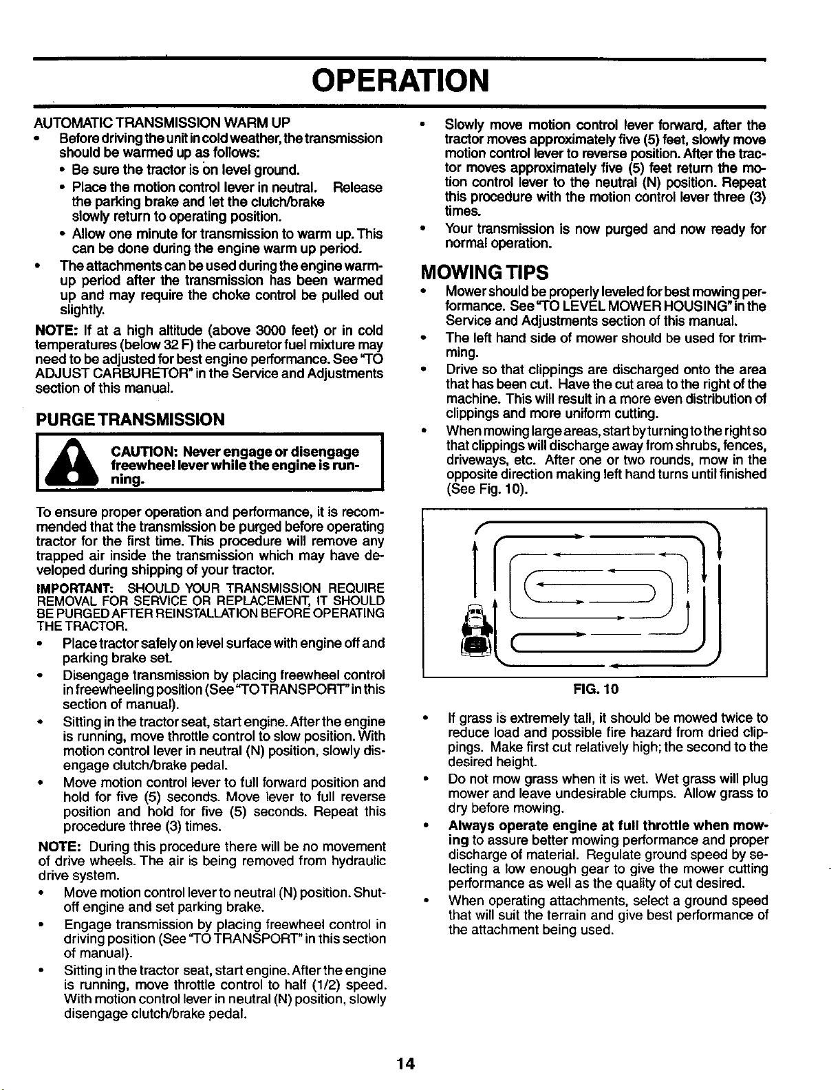
• When mowing large areas, start byturning to the rightse
that clippings willdischarge away from shrubs, fences,
driveways, etc. After one or two rounds, mow in the
opposite direction making left hand turns until finished
(See Fig. 10).
[
1
(. .-
FIG. 10
If grass isextremely tall, it should be mowed twice to
reduce load and possible fire hazard from dried clip-
pings. Make first cut relatively high;the second to the
desired height.
Do not mow grass when it is wet. Wet grass will plug
mower and leave undesirable clumps. Allow grass to
dry before mowing.
Always operate engine at full throttle when mow-
ing to assure better mowing performance and proper
discharge of material. Regulate ground speed by se-
lecting a low enough gear to give the mower cutting
performance as well as the quality ofcut desired.
When operating attachments, select a ground speed
that will suit the terrain and give best performance of
the attachment being used.
14
OPERATION
MULCHING MOWING TIPS
IMPORTANT: FOR BEST PERFORMANCE, KEEP MOWER
HOUSING FREE OF BUILT-UPGRASS AND TRASH. CLEAN
AFTER EACH USE.
• The sl_ecial mulching blade will recut the grass clip-
pings many times and reduce them in size so that as
they fall onto the lawn they willdisperse intothe grass
and not be noticed. Also,the mulched grasswillbiode-
grade quickly to provide nutrientsforthe lawn. Always
mulch with your highest engine (blade) speed as this
will provide the best recuttingaction of the blades.
• Avoidcutting your lawnwhen itiswet. Wet grass tends
to formclumps and interferes with the mulchingaction.
The best time to mow your lawn isthe early afternoon.
At this time the grass has dried, the newly cutarea will
not be exposed to direct sunlight.
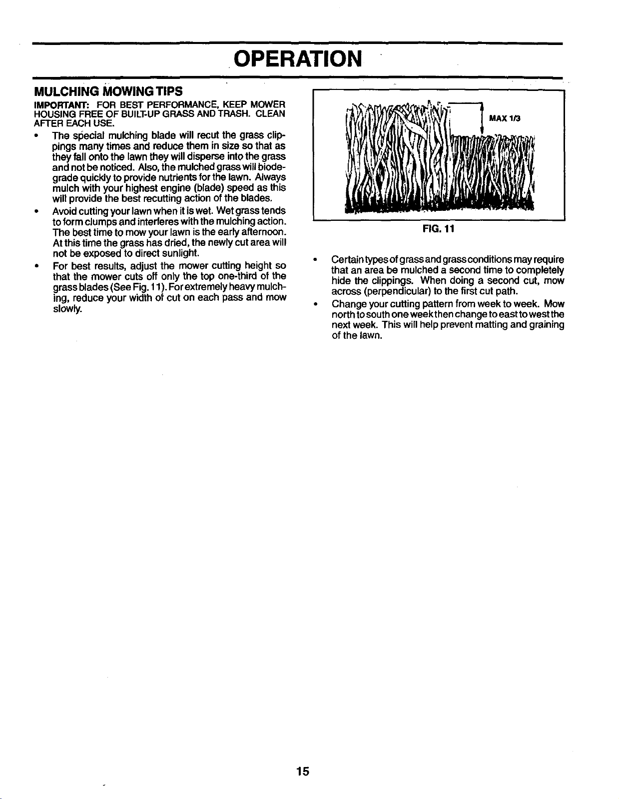
• For best results, adjust the mower cutting height so
that the mower cuts off only the top one-third of the
grass blades (See Fig. 11). Forextremely heavy mulch-
ing, reduce your width of cut on each pass and mow
slowly.
MAX 1/3
FIG. 11
• Certain typesofgrass and grassconditionsmay requira
that an area be mulched a second time to completely
hide the clippings. When doing a second cut, mow
across (perpendicular) tothe first cut path.
• Change yourcutting pattern from week to week. Mow
north tosouthone week then change toeast towest the
next week. This will help prevent matting and graining
of the lawn.
15
MAINTENANCE
I
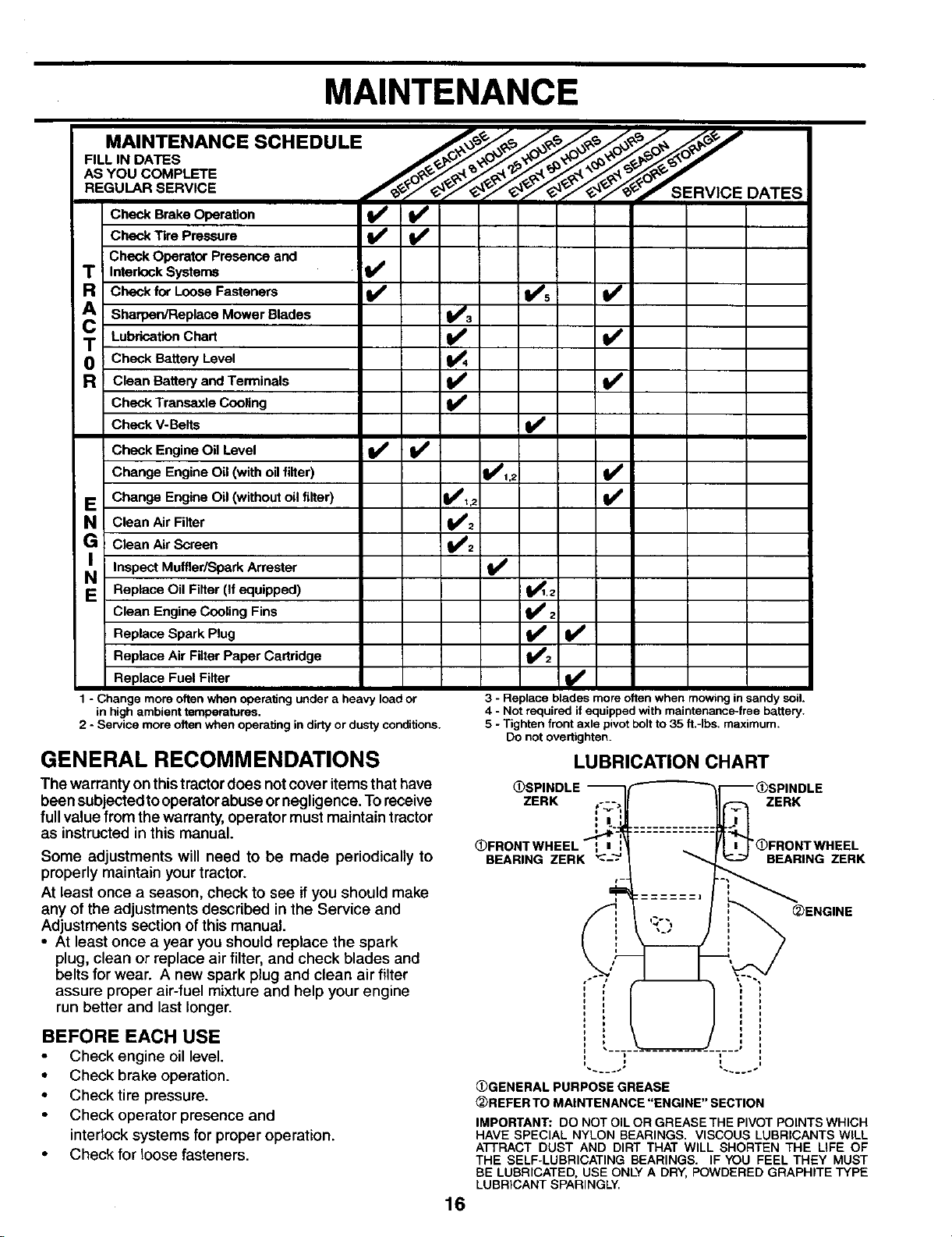
MAINTENANCE SCHEDULE _#,__/_/_'o_/_o_ _, _
FILLIN DATES /__j:_Xx_'_,p_/_._dP"
ASYOU COMPLETE f_/_._._,_ "O_OR'_"
REGO RSE.V,CE / JSERV'OE
DATES
Check BrakeOperation _
CheckTire Pressure
CheckOperatorPresenceand
TR InterlockSystems
Checkfor LooseFasteners V's I_
CA Sharpen/ReplaceM°wer Blades ;_3
; LubricationChart I_
T CheckBatteryLevel i_4
R CleanBatteryandTerminals II_
I CheckTransaxleCooling I_
CheckV-Belts I_
CheckEngineOil Level I1_
ChangeEngineOil (withoilfilter) 11_1,2 V'
E ChangeEngineOil (withoutoilfilter) 1_,2 ll_
N CleanAirFilter 1_2
G CleanAirScreen Ibm2
I InspectMuffler/SparkArrester
N
E Replace Oil Filter (If equipped) _.2
CleanEngineCoolingFins _ 2
ReplaceSparkPlug _ I1_
ReplaceAirFilterPaperCartridge
ReplaceFuelFilter
1 - Change more often when operalJng under a heavy load or
in high ambient temperatures.
2 - Service more often when operating in dirty or dusty conditions.
GENERAL RECOMMENDATIONS
3 - Replace blades more often when mowing in sandy soil
4 - Not required if equipped with maintenance_free battery.
5 - Tighten front axle pivotbolt to 35 ft.-Ibs, maximum.
Do not overtighten.
LUBRICATION CHART
The warranty on thistractor does not cover itemsthat have
been subjected tooperatorabuse or negligence. To receive
full value from the warranty, operator must maintain tractor
as instructed in this manual.
Some adjustments will need to be made periodically to
properly maintain your tractor.
At least once a season, check to see if you should make
any of the adjustments described in the Service and
Adjustments section of this manual.
• At least once a year you should replace the spark
plug, clean or replace air filter, and check blades and
belts for wear. A new spark plug and clean air filter
assure proper air-fuel mixture and help your engine
run better and last longer.
BEFORE EACH USE
Check engine oil level.
• Check brake operation.
• Check tire pressure.
• Check operator presence and
interlocksystems for proper operation.
• Check for loose fasteners.
OSPII
ZERK t-7,-, ZERK
OFRONTWHEEL _ z "C)FRONTWHEEL
BEARING ZERK BEARING ZERK
_)ENGINE
(i)GENERAL PURPOSE GREASE
_REFERTO MAINTENANCE "ENGINE" SECTION
IMPORTANT: DO NOT OIL OR GREASE THE PIVOT POINTS WHICH
HAVE SPECIAL NYLON BEARINGS. VISCOUS LUBRICANTS WILL
ATI-RACT DUST AND DIRT THAT WILL SHORTEN THE LIFE OF
THE SELF-LUBRICATING BEARINGS. IF YOU FEEL THEY MUST
BE LUBRICATED, USE ONLY A DRY, POWDERED GRAPHITE TYPE
LUBRICANT SPARINGLY.
16
MAINTENANCE
,=
TRNMNG MANDREL
ASSEMBLY
TRACTOR
Always observe safety rules when performing any main-
tenance.
BRAKE OPERATION
If tractor requires more than six (6) feet stopping distance
at highspeed inhighest gear,then brake must beadjusted.
(See "TO ADJUST BRAKE"inthe Service and Adjustments
section ofthis manual).
TIRES
• Maintain properairpressure inalltires (See "PRODUCT
SPECIFICATIONS" section of this manual).
• Keep tires free of gasoline, oil, or insect controlchemi-
cals which can harm rubber.
• Avoid stumps, stones, deep ruts, sharp objects and
other hazards that may cause tire damage.
NOTE: To seal tire punctures and prevent flat tires due to
slow leaks, tire sealant may be purchased from your local
parts dealer. Tire sealant also prevents tire dry rot and
corrosion.
OPERATOR PRESENCE SYSTEM
Be sure operator presence and interlocksystems ere work-
ing properly. If your tractor does notfunction as described,
repair the problem immediately.
• The engine should not start unless the clutch/brake
pedal isfully depressed and attachement clutchcontrol
is in the disengaged position.
• When the engine isrunning,anyattempt bythe operator
to leave the seat without first setting the parking brake
should shut offthe engine.
• When the engine is running and the attachment clutch
is engaged, any attempt by the operator to leave the
seat should shut off the engine.
• The attachment clutch should never operate unless
the operator is in the seat.
BLADE CARE
Forbestresultsmower bladesmust bekeptsharp. Replace
bent or damaged blades.
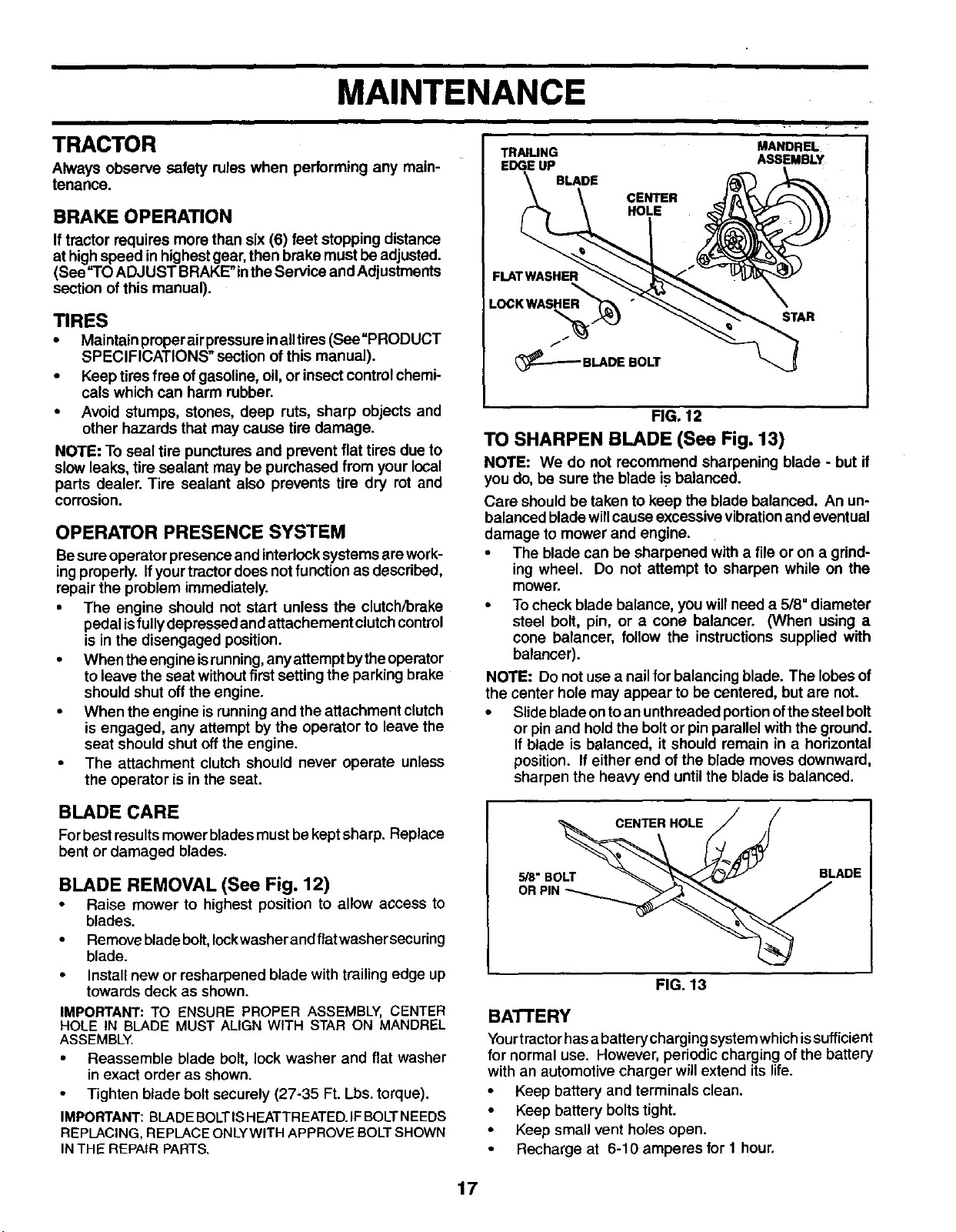
BLADE REMOVAL (See Fig. 12)
• Raise mower to highest position to allow access to
blades.
• Remove blade bolt, Iockwasher and flat washer securing
blade.
• Install new or resharpened blade with trailing edge up
towards deck as shown.
IMPORTANT:TO ENSURE PROPER ASSEMBLY, CENTER
HOLE IN BLADE MUST ALIGN WITH STAR ON MANDREL
ASSEMBLY.
• Reassemble blade bolt, lock washer and flat washer
in exact order as shown.
• Tighten blade bolt securely (27-35 Ft. Lbs.torque).
IMPORTANT: BLADE BOLTIS HEATTREATED.IF BOLT NEEDS
REPLACING, REPLACE ONLYWITH APPROVE BOLT SHOWN
IN THE REPAIR PARTS.
CENTER
HOLE
STAR
FIG. 12
TO SHARPEN BLADE (See Fig. 13)
NOTE: We do not recommend sharpening blade - but if
you do, be sure the blade iF balanced.
Care should be taken to keep the blade balanced. An un-
balanced blade willcause excessivevibrationand eventual
damage to mower and engine.
• The blade can be sharpened with a file or on a grind-
ing wheel. Do not attempt to sharpen while on the
mower.
• Tocheck blade balance, you willneed a 5/8=diameter
steel bolt, pin, or a cone balancer. ONhen using a
cone balancer, follow the instructions supplied with
balancer).
NOTE: Do not use a nail for balancing blade. The lobesof
the center hole may appear to be centered, but are not.
• Slide blade onto an unthreaded portionofthe steelbolt
or pin and hold the bolt or pin parallel with the ground.
If blade is balanced, it should remain in a horizontal
position. If either end ofthe blade moves downward,
sharpen the heavy end until the blade is balanced.
OR PIN _
FIG. 13
BATTERY
Yourtrectorhasa batterycharging systemwhichissufficient
for normal use. However, periodic charging of the battery
with an automotive charger will extend its life.
• Keep battery and terminals clean.
• Keep battery boltstight.
• Keep small vent holes open.
• Recharge at 6-10 amperes for 1 hour.
17
MAINTENANCE
NOTE: The original equipment battery on your tractor is
maintenance free. Do not attempt to open or remove caps
or covers. Adding or checking level of electrolyte is not
necessary.
TO CLEAN BATTERY AND TERMINALS
Corrosion and dirt on the battery and terminals can cause
the battery to "leak" power.
• Disconnect BLACK battery cable first then RED bat-
tery cable and remove battery from tractor.
• Rinse the battery with plain water and dry.
• Clean terminals and battery cable ends withwire brush
until bright.
• Coat terminals with grease or petroleum jelly.
• Reinstall battery (See "REPLACING BAI-I-ERY" in
the SERVICE AND ADJUSTMENTS section of this
manual).
V-BELTS
Check V-belts for deterioration and wear after 100 hours
of operation and replace if necessary. The belts are not
adjustable. Replace belts ifthey begin to slip from wear.
TRANSAXLE COOLING
The transmission fan and cooling fins should be keptclean
to assure proper cooling.
Do not attempt to clean fan or transmission while engine
is runningor while the transmission ishot.To prevent pos-
sible damage to seals, do not use high pressure water or
steam to clean transexle.
• Inspectcooling fan to be sure fan blades are intact and
clean.
• Inspect cooling fins for dirt, grass clippings and other
materials. To prevent damage to seals, do not use
compressed air or high pressure sprayer toclean cool-
ingfins.
TRANSAXLE PUMP FLUID
The transaxle was sealed at the factory and fluid mainte-
nance is not required for the life of the transaxle. Should
the transaxle ever leak or require servicing, contact your
nearest authorized service center/department.
ENGINE
LUBRICATION
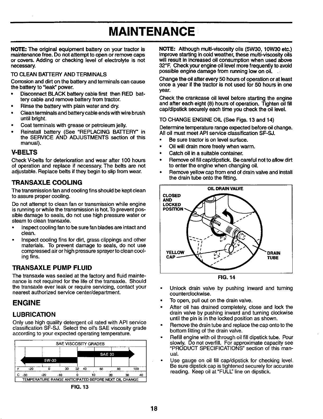
Only use high quality detergent oil rated with API service
classification SF-SJ. Select the oil's SAE viscosity grade
according to your expected operating temperature.
SAE VISCOSITY GRADES
-20 0 30 32 40 60 80 100
TEMPERATURE RANGE ANTICtPATED BEFORE NEXT OIL CHANGE
FIG. 13
NOTE: Although multi-viscosityoils (5W30, 10W30 etc.)
improve starting in cold weather, these multi-viscosityoils
will result in increased oil consumption when used above
32°F. Check yourengine oil level more frequently toavoid
possible engine damage from running low on oil.
Change the oilafter every 50 hours ofoperation orat least
once a year ifthe tractor is not used for 50 hours in one
year.
Check the crankcase oil level before starting the engine
and after each eight (8) hours of operation. Tighten oilfill
cap/dipstick securely each time you check the oil level.
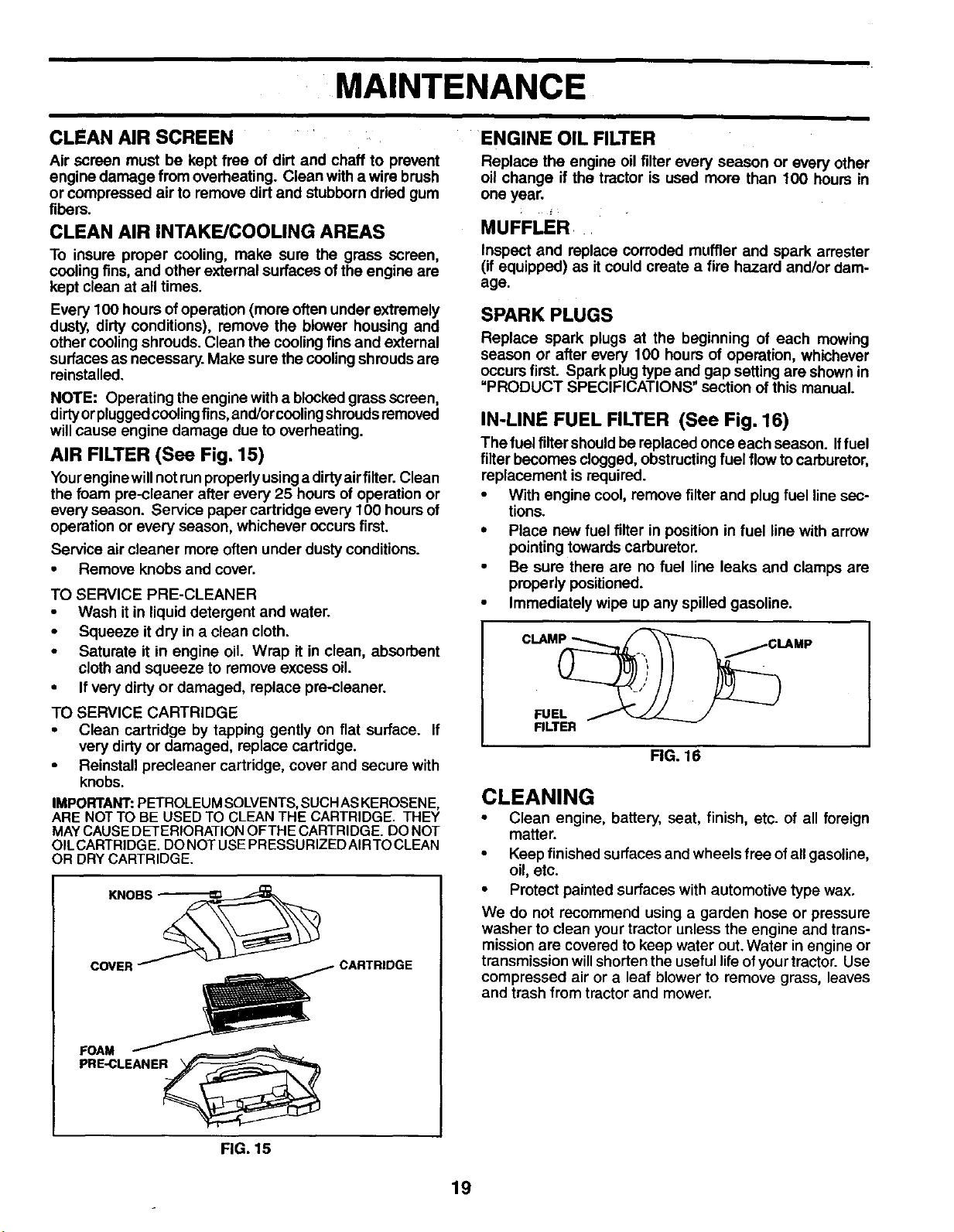
TO CHANGE ENGINE OIL (See Figs. 13 and 14)
Determine temperature range expected before oilchange.
All oil must meet API service classification SF-SJ.
• Be sure tractor is on level surface.
• Oil will drain more freely when warm.
• Catch oil in a suitable container.
• Remove oilfill cap/dipstick. Becareful not to allowdirt
to enter the engine when changing oil.
• Remove yellowcap from end ofdrain valve and install
the drain tube onto the fitting.
CLOSED
AND
LOCKED
OIL DRAIN VALVE
YELLOW
CAf TUBE
FIG. 14
Unlock drain valve by pushing inward and turning
counterclockwise.
• To open, pull out on the drain valve.
• After oil has drained completely, close and lock the
drain valve by pushing inward and turning clockwise
until the pin is inthe locked position as shown.
• Remove thedrain tube and replace the cap ontoto the
bottom fitting of the drain valve.
Refill engine with oilthrough oilfill dipstick tube. Pour
slowly. Do not overfilL For approximate capacity see
"PRODUCT SPECIFICATIONS" section of this man-
ual.
• Use gauge on oil fill cap/dipstick for checking level.
Be sure dipstickcap istightened securely for accurate
reading. Keep oilat "FULL" line on dipstick.
18
MAINTENANCE
ENGINE OIL FILTERCLEAN AIR SCREEN _
Air screen must be kept free of dirt and chaff to prevent
engine damage from overheating. Clean with a wire brush
or compressed air to remove dirt and stubborn dried gum
fibers.
CLEAN AIR INTAKE/COOLING AREAS
To insure proper cooling, make sure the grass screen,
cooling fins,and other external surfaces of the engine are
kept clean at all times.
Every 100 hours of operation (more often under extremely
dusty, dirty conditions), remove the blower housing and
other cooling shrouds. Clean the coolingfins and external
surfaces as necessary. Make sure the coolingshrouds are
reinstalled.
NOTE: Operating the engine witha blookedgrossscreen,
dirtyorplugged coolingfins, and/orcoolingshroudsremoved
willcause engine damage due to overheating.
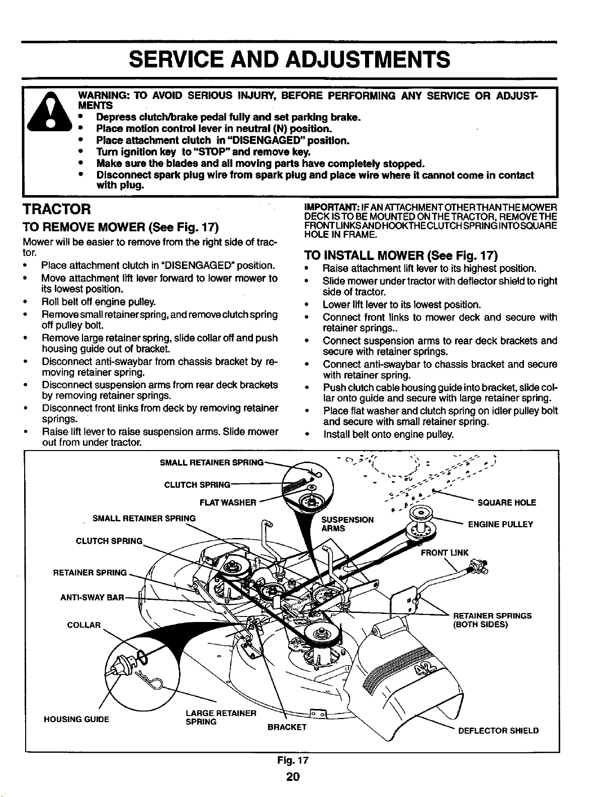
AIR FILTER (See Fig. 15)
Yourenginewillnot runproperlyusinga dirtyairfilter. Clean
the foam pre-cleaner after every 25 hours of operation or
every season. Service paper cartridge every 100 hours of
operation or every season, whichever occurs first.
Service air cleaner more often under dusty conditions.
• Remove knobs and cover.
TO SERVICE PRE-CLEANER
• Wash it in liquid detergent and water.
• Squeeze it dry in a clean cloth.
• Saturate it in engine oil. Wrap it in clean, absorbent
cloth and squeeze to remove excess oil.
• If very dirty or damaged, replace pre-cleaner.
TO SERVICE CARTRIDGE
• Clean cartridge by tapping gently on flat surface. If
very dirty or damaged, replace cartridge.
• Reinstall precleaner cartridge, cover and secure with
knobs.
IMPORTANT: PETROLEUM SOLVENTS, SUCH AS KEROSENE,
ARE NOT TO BE USED TO CLEAN THE CARTRIDGE. THEY
MAY CAUSE DETERIORATION OFTHE CARTRIDGE. DO NOT
OILCARTRIDGE. DO NOT USE PRESSURIZED AIRTO CLEAN
OR DRY CARTRIDGE.
FOAM _ CARTRIDGE
PRE-CLEANER_
FIG. 15
Replace the engine oil filter every season or every other
oil change if the tractor is used more than 100 hours in
one year.
MUFFLER,
Inspect and replace corroded muffler and spark arroster
(if equipped) as it could create a fire hazard and/or dam-
age.
SPARK PLUGS
Replace spark plugs at the beginning of each mowing
season or after every 100 hours of operation, whichever
occurs first. Spark plug type and gap setting are shownin
"PRODUCT SPECIFICATIONS" section ofthis manual.
IN-LINE FUEL FILTER (See Fig. 16)
The fuel filtershouldbe replaced once each season. Iffuel
filterbecomes clogged, obstructingfuel flow to carburetor,
replacement is required.
• With engine cool, remove filter and plug fuel linesec-
tions.
• Place new fuel filter in position in fuel line with arrow
pointingtowards carburetor.
• Be sure there are no fuel line leaks and clamps are
properly positioned.
• Immediately wipe up any spilled gasoline.
FILTER
FIG. 16
CLEANING
• Clean engine, battery, seat, finish, etc. of all foreign
matter.
• Keep finished surfaces and wheels free ofall gasoline,
oil, etc.
• Protect painted surfaces with automotive type wax.
We do not recommend using a garden hose or pressure
washer to clean your tractor unless the engine and trans-
mission are covered to keep water out.Water in engine or
transmission willshorten the useful lifeofyour tractor. Use
compressed air or a leaf blower to remove grass, leaves
and trash from tractorand mower.
19
SERVICE AND ADJUSTMENTS
WARNING: TO AVOID SERIOUS INJURY, BEFORE PERFORMING ANY SERVICE OR ADJUST-
MENTS
• Depress clutch/brake pedal fully and set parklng brake.
• Place motion control lever in neutral (N) position.
• Place attachment clutch in "DISENGAGED" position.
• Turn ignitlon key to"STOP" and remove key.
• Make sure the blades and all moving parts have completely stopped.
• Dlsconnect spark plug wire from spark plug and place wire where it cannot come in contact
with plug.
TRACTOR
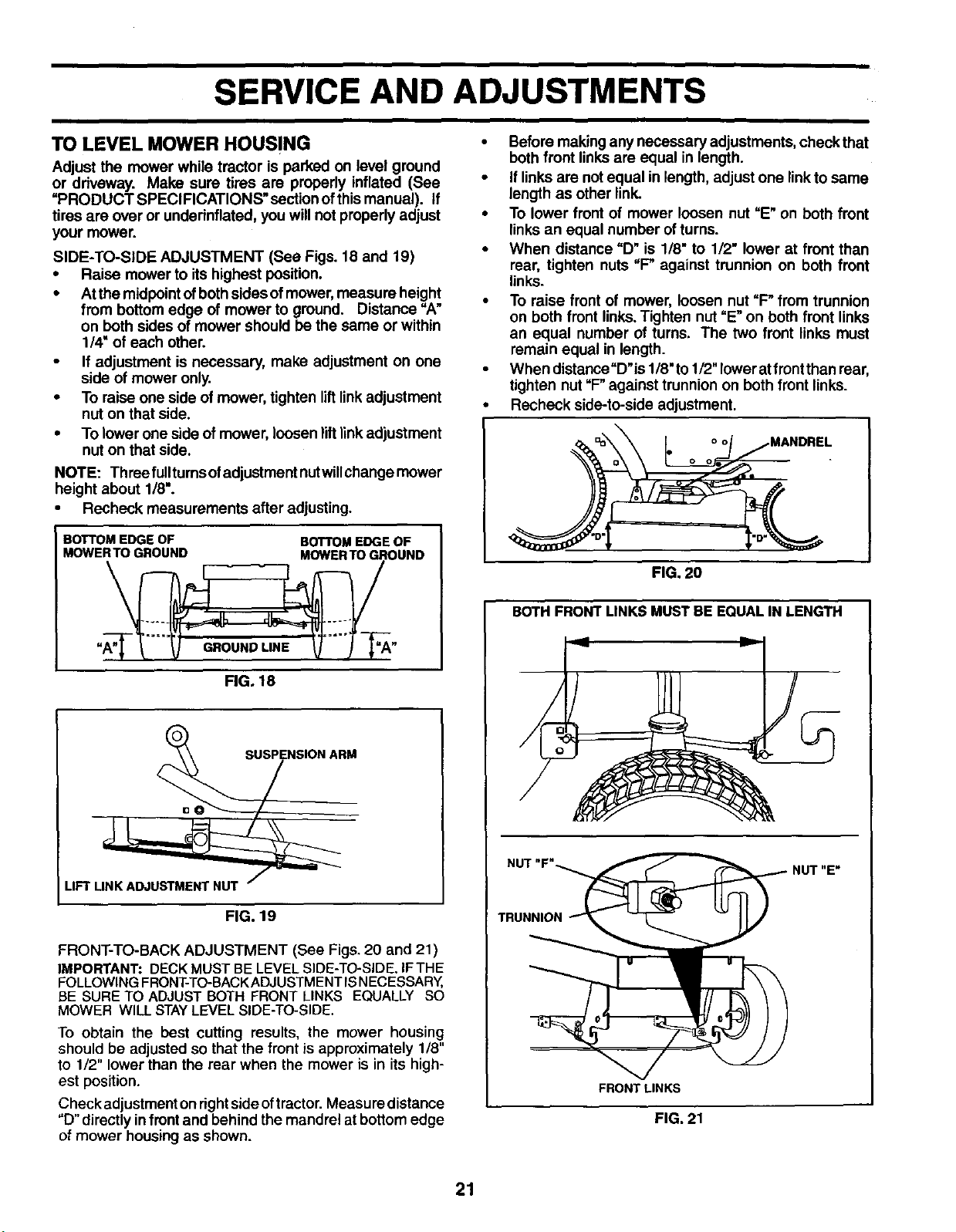
TO REMOVE MOWER (See Fig. 17)
Mower will be easier to remove from the right side of trac-
tor.
• Place attachment clutch in =DISENGAGED" position.
• Move attachment lift lever forward to lower mower to
its lowest position.
• Roll belt off engine pulley.
• Remove small retainerspring, and remove clutchspring
off pulley bolt.
• Remove large retainer spring, slidecollar off and push
housing guide out of bracket.
• Disconnect anti-swaybar from chassis bracket by re-
moving retainer spring.
• Disconnect suspension arms from rear deck brackets
by removing retainer springs.
• Disconnect front linksfrom deck by removing retainer
springs.
• Raise lift lever to raise suspension arms. Slide mower
out from under tractor.
IMPORTANT: IF AN A'I-I'ACHMENT OTHERTHAN TH EMOWER
DECK ISTO BE MOUNTED ONTHE TRACTOR, REMOVETHE
FRONTLINKSAND HOOKTHECLUTCH SPRING INTOSQUARE
HOLE IN FRAME.
SMALL RETAINER
CLUTCH SPRING'
SMALL RETAINERSPRING
CLUTCH SPRING
TO INSTALL MOWER (See Fig. 17)
• Raise attachment lift lever to its highest position.
• Slide mower under tractorwith deflector shieldto right
side of tractor.
• Lower liftlever to its lowest position.
• Connect front links to mower deck and secure with
retainer springs..
• Connect suspension arms to rear deck brackets and
secure with retainer springs.
• Connect anti-swaybar to chassis bracket and secure
with retainer spring.
• Push clutchcable housingguide intobracket, slidecol-
lar onto guide and secure with large retainer spring.
• Place flat washer and clutch springon idler pulley bolt
and secure with small retainer spring.
• Install belt onto engine pulley.
__ SQUARE HOLE
ENGINE PULLEY
FRONT LINK
RETAINER .=
ANTI-SWAY
COLLAR
RETAINER SPRINGS
(BOTH SIDES)
HOUSING GUIDE
LARGE RETAINER
SPRING
BRACKET
DEFLECTOR SHIELD
Fig. 17
2O
SERVICE AND ADJUSTMENTS
TO LEVEL MOWER HOUSING
Adjust the mower while tractor is parked on level ground
or driveway. Make sure tires are properly inflated (See
"PRODUCT SPECIFICATIONS" secUonofthis manual). If
tires are over or undednflated, you will not properly adjust
your mower.
SIDE-TO-SIDE ADJUSTMENT (See Figs. 18 and 19)
• Raise mower to its highest position.
• Atthe midpointofbothsides of mower,measure height
from bottom edge of mower to ground. Distance "A"
on both sides of mower should be the same or within
1/4" of each other.
• If adjustment is necessary, make adjustment on one
side of mower only.
• To raise one side of mower, tighten liftlinkadjustment
nut on that side.
• To lower one side of mower, loosen liftlinkadjustment
nut on that side.
NOTE: Three fulltums ofadjustment nutwUlchangemower
height about 1/8".
• Recheck measurements after adjusting.
BOTTOM EDGE OF BOTTOM EDGE OF
MOWERTO GROUND MOWER TO GROUND
RG, 18
FIG. 19
FRONT-TO-BACK ADJUSTMENT (See Figs. 20 and 21 )
IMPORTANT: DECK MUST BE LEVEL SIDE-TO-SIDE. IFTHE
FOLLOWING FRONT-TO-BACK ADJUSTM ENTIS NECESSARY,
BE SURE TO ADJUST BOTH FRONT LINKS EQUALLY SO
MOWER WILL STAY LEVEL SIDE-TO-SIDE.
To obtain the best cutting results, the mower housing
should be adjusted so that the front is approximately 1/8"
to 1/2" lower than the rear when the mower is in its high-
est position.
Check adjustment on right side oftractor. Measure distance
"D°directly in front and behind the mandrel at bottom edge
of mower housing as shown.
• Before makingany necessary adjustments, checkthat
both front linksare equal in length.
• If linksare not equal in length, adjust one linkto same
length as other link.
• To lower front of mower loosen nut =E"on both front
linksan equal number ofturns.
• When distance "D" is 1/8" to 1/2" lower at front than
rear, tighten nuts "P against trunnion on both front
links.
• To raise front of mower, loosen nut "P from trunnion
on both front links.Tighten nut =E"on both front links
an equal number of turns. The two front links must
remain equal in length.
• When distance"D'is 1/8"to1/2"lowerat front than rear,
tighten nut "P against trunnion on both front links.
Recheck side-to-side adjustment.
_. _,_ L ° ':'J _1 MANDREL
13 0 0 • "
FIG. 20
BOTHFRONT LINKS MUST BE EQUALIN LENGTH
NUT "E"
TRUNNION
FRONTLINKS
FIG. 21
21
SERVICE AND ADJUSTMENTS
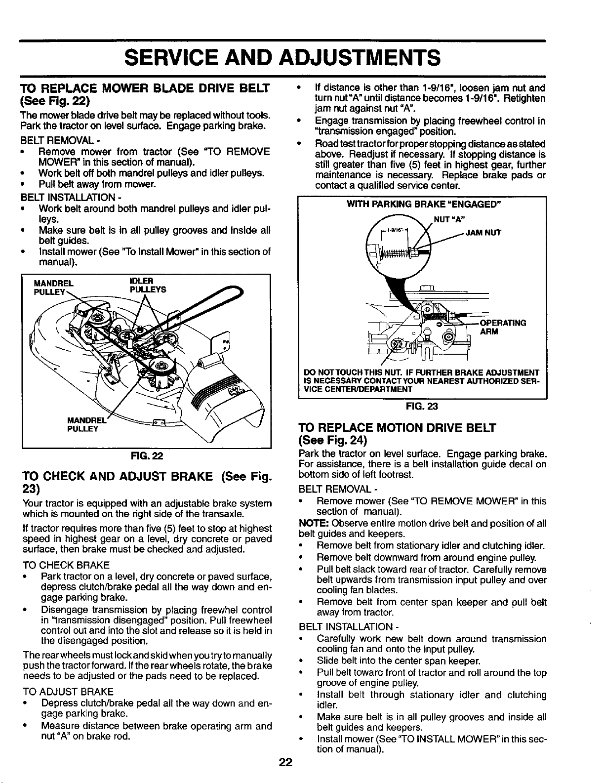
TO REPLACE MOWER BLADE DRIVE BELT
(See Fig. 22)
The mower blade drive belt may be replaced without tools.
Park the tractor on level surface. Engage parking brake.
BELT REMOVAL -
• Remove mower from tractor (See "TO REMOVE
MOWER" in this section of manual).
• Work belt off both mandrel pulleys and idler pulleys.
• Pull belt away from mower.
BELT INSTALLATION -
• Work belt around both mandrel pulleys and idler pul-
leys.
• Make sure belt is in all pulley grooves and inside all
belt guides.
• Install mower (See "To Install Mower" in this section of
manual).
MANDREL IDLER
PULLEYS
PULLEY
FIG. 22
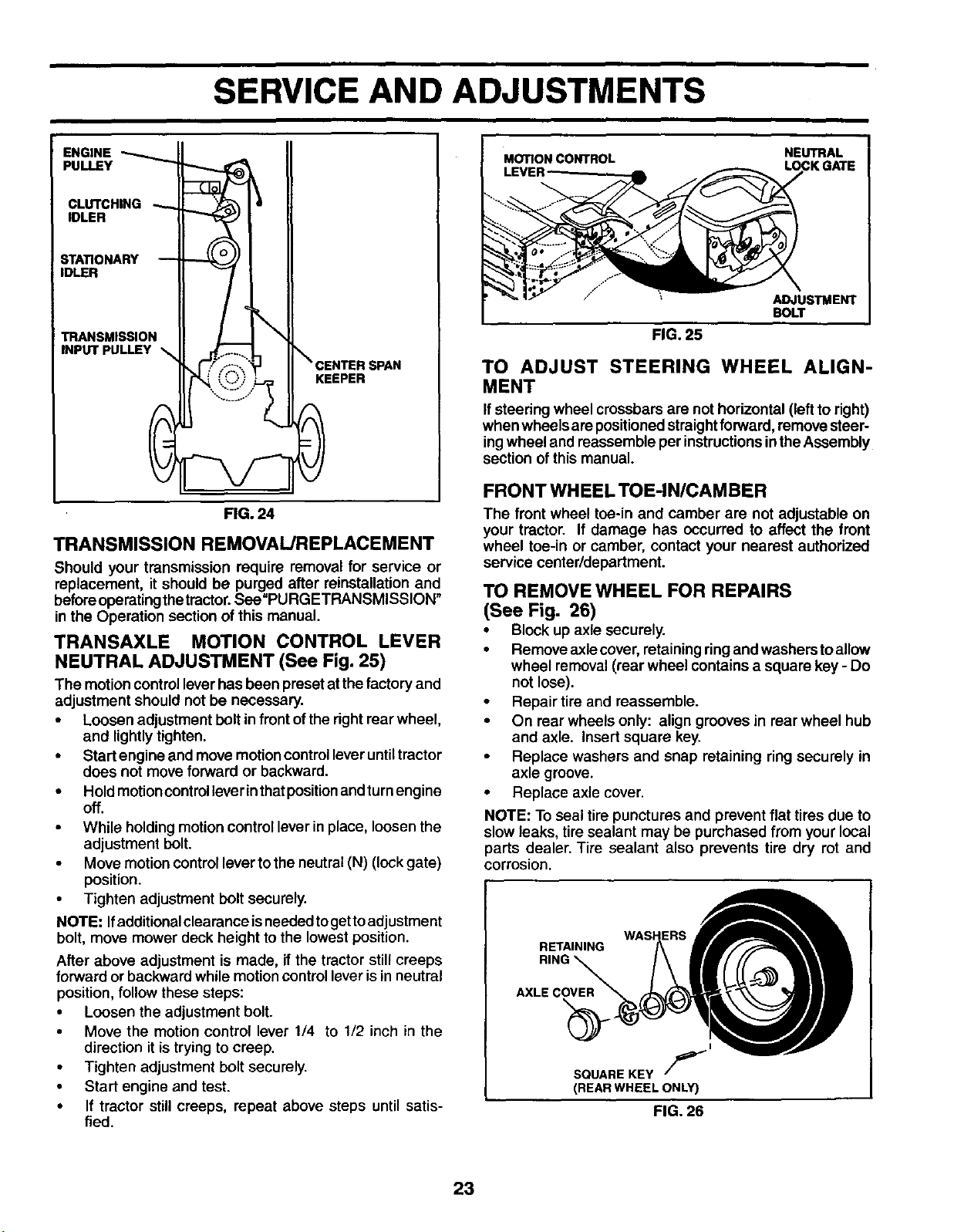
TO CHECK AND ADJUST BRAKE (See Fig.
23)
Your tractor is equipped with an adjustable brake system
which is mounted on the rightside ofthe transaxle.
Iftractor requires more than five (5) feet to stop at highest
speed in highest gear on a level, dry concrete or paved
surface, then brake must be checked and adjusted.
TO CHECK BRAKE
• Park tractor on a level, dry concrete or paved surface,
depress clutch/brake pedal all the way down and en-
gage parking brake.
• Disengage transmission by placing freewhel control
in "transmission disengaged" position. Pull freewheel
control out and intothe slot and release so itis held in
the disengaged position.
The rearwheels must lockand skidwhen youtrytomanually
push thetractorforward, Ifthe rearwheels rotate,the brake
needs to be adjusted or the pads need to be replaced.
TO ADJUST BRAKE
• Depress clutch/brake pedal all the way down and en-
gage parking brake.
• Measure distance between brake operating arm and
nut "A" on brake rod.
• If distance is other than 1-9/16", loosen jam nut and
turn nut"A" untildistance becomes 1-9/16". Retighten
jam nutagainst nut "A".
• Engage transmission by placing freewheel control in
"transmission engaged" position.
• Road test tractor for proper stopping distance as stated
above. Readjust if necessary. If stopping distance is
still greater than five (5) feet in highest gear, further
maintenance is necessary. Replace brake pads or
contact a qualified service center.
WITH PARKING BRAKE "ENGAGED"
)PERATING
ARM
22
DO NOTTOUCHTHIS NUT. IF FURTHER BRAKE ADJUSTMENT
IS NECESSARY CONTACTYOUR NEAREST AUTHORIZED SER-
VICE CENTER/DEPARTMENT
FIG. 23
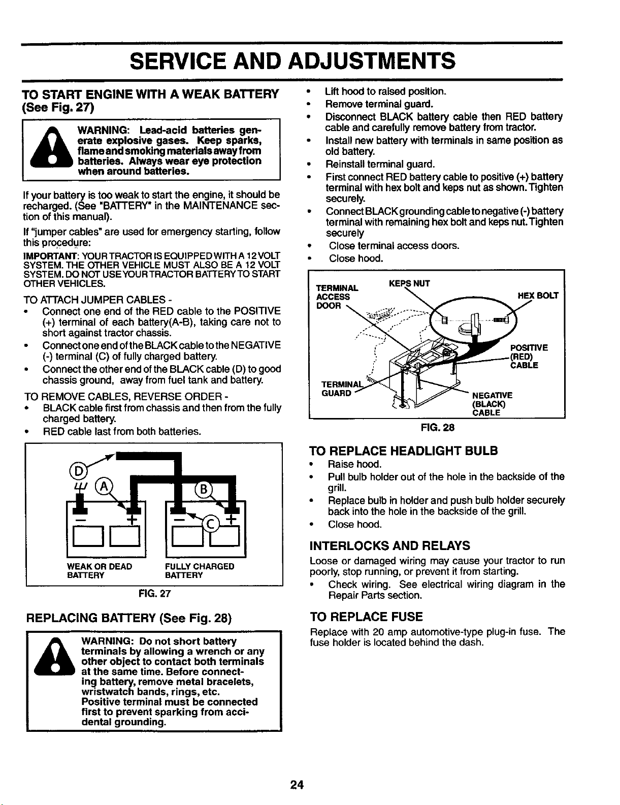
TO REPLACE MOTION DRIVE BELT
(See Fig. 24)
Park the tractor on level surface. Engage parking brake.
For assistance, there is a belt installation guide decal on
bottom side of left footrest.
BELT REMOVAL -
• Remove mower (See "TO REMOVE MOWER" in this
section of manual).
NOTE: Observe entire motiondrive belt and position ofall
belt guides and keepers.
• Remove belt from stationary idler and clutching idler.
• Remove belt downward from around engine pulley.
• Pullbelt slack toward rear of tractor. Carefully remove
belt upwards from transmission input pulley and over
cooling fan blades.
• Remove belt from center span keeper and pull belt
away from tractor.
BELT INSTALLATION -
Carefully work new belt down around transmission
cooling fan and onto the input pulley.
• Slide belt into the center span keeper.
• Pull belt toward front of tractor and rollaround the top
groove of engine pulley.
• Install belt through stationary idler and clutching
idler.
• Make sure belt is in all pulley grooves and inside all
belt guides and keepers.
• Install mower (See "TO INSTALL MOWER" inthis sec-
tion of manual).
SERVICE AND ADJUSTMENTS
NEUTRAL
ENGINE
PULLEY
CLUTCHING
IDLER
STATIONARY --
IDLER
TRANSMISSION
INPUT PULLEY
CENTER SPAN
KEEPER
FIG. 24
TRANSMISSION REMOVAL/REPLACEMENT
Should your transmission require removal for service or
replacement, it should be purged after reinstallation and
beforeoperatingthetractor.See"PURGETRANSMISSION"
in the Operation section of this manual.
TRANSAXLE MOTION CONTROL LEVER
NEUTRAL ADJUSTMENT (See Fig. 25)
The motioncontrollever has been preset atthe factory and
adjustment should not be necessary.
• Loosen adjustment bolt in front of the right rear wheel,
and lightly tighten.
• Start engine and move motion control lever until tractor
does not move forward or backward.
• Hold motion control lever inthat position and turn engine
off.
• While holding motion control lever in place, loosen the
adjustment bolt.
• Move motion control lever to the neutral (N) (lock gate)
position.
• Tighten adjustment bolt securely.
NOTE: Ifadditionalclearance isneeded to getto adjustment
bolt, move mower deck height to the lowest position.
After above adjustment is made, if the tractor still creeps
forward or backward while motion control lever is in neutral
position, follow these steps:
• Loosen the adjustment bolt.
• Move the motion control lever 1/4 to 1/2 inch in the
direction it is trying to creep.
• Tighten adjustment bolt securely.
• Start engine and test.
• If tractor still creeps, repeat above steps until satis-
fied.
MOTION CONTROL
LEVER
ADJUSTMENT
BOLT
FIG. 25
TO ADJUST STEERING WHEEL ALIGN-
MENT
If steering wheel crossbars are not horizontal (leftto right)
when wheels are positioned straight forward, remove steer-
ing wheel and reassemble per instructions in the Assembly
section of this manual.
FRONT WHEEL TOE-IN/CAMBER
The front wheel toe-in and camber are not adjustable on
your tractor. If damage has occurred to affect the front
wheel toe-in or camber, contact your nearest authorized
service center/department.
TO REMOVE WHEEL FOR REPAIRS
(See Fig. 26)
• Block up axle securely.
• Remove axlecover, rataining ring and washers toallow
wheel removal(rear wheel contains a square key - Do
not lose).
• Repair tire and reassemble.
• On rear wheels only: align grooves in rear wheel hub
and axle. Insert square key,
• Replace washers and snap retaining ring securely in
axle groove.
• Replace axle cover.
NOTE: To seal tire punctures and prevent flat tires due to
slow leaks, tire sealant may be purchased from your local
parts dealer. Tire sealant also prevents tire dry rot and
corrosion.
WASHERS
RETAINING
RING
AXLE COVER
I
SQUARE KEY //_
(REAR WHEEL ONL_
FIG.26
23
SERVICE AND ADJUSTMENTS
TO START ENGINE WITH A WEAK BATTERY
(See Fig. 27)
I& WARNING: Lead-acid batteries gem 1
erate explosive gases. Keep sparks,
flame and smoking materials away from
batteries. Always wear eye protection
when around batteries.
Ifyour battery istoo weak to start the engine, itshould be
recharged. (See "BATTERY" in the MAINTENANCE sec-
tion of this manual).
If"jumper cables"are used for emergency starting, follow
this proced.ure:
IMPORTANT:YOURTRACTORIS EQUIPPEDWlTH A 12VOLT
SYSTEM.THE OTHER VEHICLE MUST ALSO BE A 12 VOLT
SYSTEM.DO NOT USEYOURTRACTOR BATTERYTO START
OTHERVEHICLES.
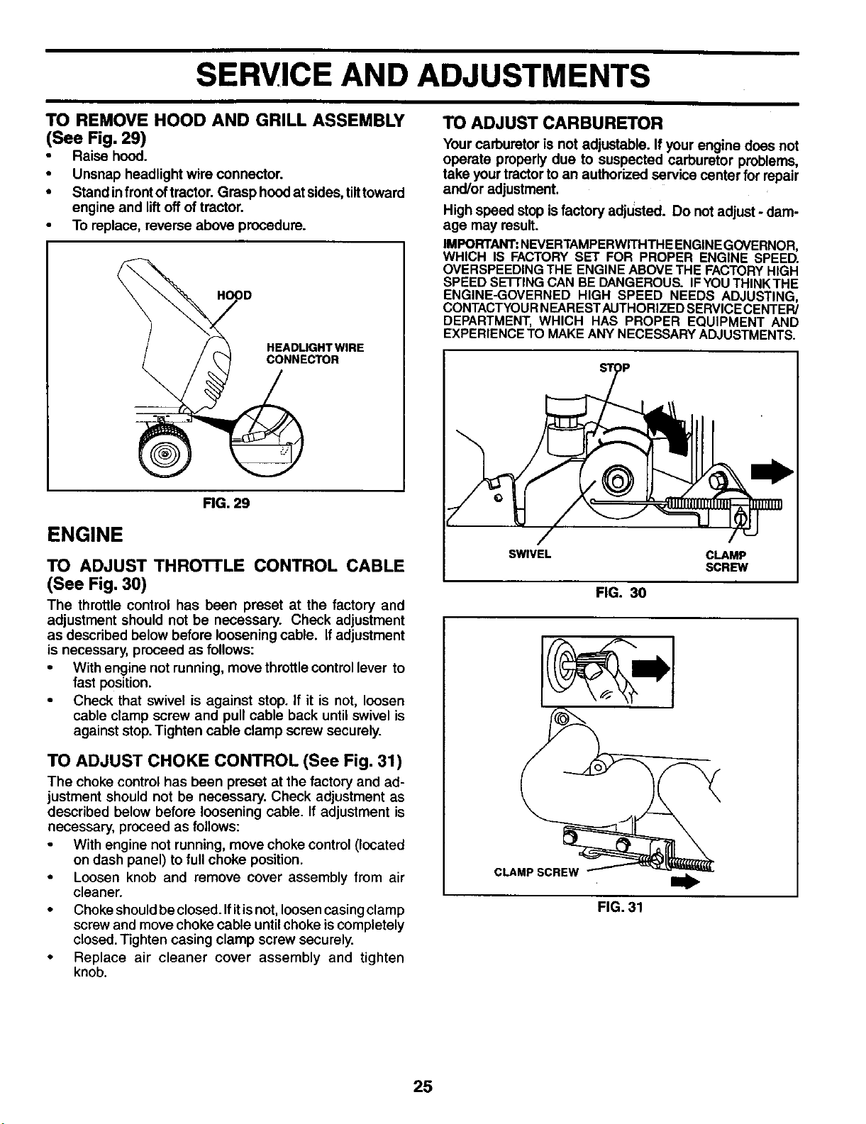
TO ATTACH JUMPER CABLES -
• Connect one end of the RED cable to the POSITIVE
(+) terminal of each battery(A-B), taking care not to
short against tractor chassis.
• Connect one end ofthe BLACK cable totheNEGATIVE
(-) terminal (C) of fully charged battery.
• Connect the other end ofthe BLACK cable (D) togood
chassis ground, away from fuel tank and battery.
TO REMOVE CABLES, REVERSE ORDER -
• BLACK cable first from chassis and then from the fully
charged battery.
• RED cable last from both batteries.
WEAK OR DEAD FULLY CHARGED
BATrERY BATTERY
FIG. 27
REPLACING BATI'ERY (See Fig. 28)
WARNING: Do not short battery
terminals by allowing a wrench or any
other object to contact both terminals
at the same time. Before connect-
ing battery, remove metal bracelets,
wristwatch bands, rings, etc.
Positive terminal must be connected
first to prevent sparking from acci-
dental grounding•
• Lift hood to raised position.
• Remove terminal guard.
• Disconnect BLACK battery cable then RED battery
cable and carefully remove battery from tractor.
• Install new battery with terminals in same position as
old battery.
• Reinstall terminal guard.
• Firstconnect RED battery cable to positive(+) battery
terminal with hex bolt and keps nut as shown.Tighten
securely.
• Connect BLACKgroundingcable tonegative(-) battery
terminal with remaining hex boltend keps nut.Tighten
securely
• Close terminal access doors.
• Close hood.
TERMINAL
ACCESS
DOOR
;NUT
HEXBOLT
i" POSITIVE
CABLE
GUARD
<, (BLACK)
CABLE
FIG. 28
TO REPLACE HEADLIGHT BULB
• Raise hood.
• Pull bulb holder out of the hole in the backside of the
grill.
• Replace bulb in holder and push bulb holdersecurely
back intothe hole in the backside ofthe grill.
• Close hood.
INTERLOCKS AND RELAYS
Loose or damaged wiring may cause your tractor to run
poorly, stop running, or prevent it from starting.
• Check wiring. See electrical wiring diagram in the
Repair Parts section.
TO REPLACE FUSE
Replace with 20 amp automotive-type plug-in fuse. The
fuse holder is located behind the dash.
24
SERVICE AND ADJUSTMENTS
TO REMOVE HOOD AND GRILL ASSEMBLY TO ADJUST CARBURETOR
(See Fig. 29)
• Raise hood.
• Unsnap headlight wire connector.
• Standinfrontoftractor. Grasphoodatsides, tilttoward
engine and liftoff of tractor.
• To replace, reverse above procedure.
HEADLIGHTWIRE
CONNECTOR
RG. 29
ENGINE
TO ADJUST THRO'B'LE CONTROL CABLE
(See Fig. 30)
The throttle control has been preset at the factory and
adjustment should not be necessary. Check adjustment
as described below before loosening cable. Ifadjustment
is necessary, proceed as follows:
• With engine not running, move throttle control lever to
fast position.
• Check that swivel is against stop. If it is not, loosen
cable clamp screw and pull cable back until swivel is
against stop.Tighten cable clamp screw securely.
TO ADJUST CHOKE CONTROL (See Fig. 31)
The choke control has been preset at the factory and ad-
justment should not be necessary. Check adjustment as
described below before loosening cable. If adjustment is
necessary, proceed as follows:
With engine not running, move choke control (located
on dash panel) to full choke position.
• Loosen knob and remove cover assembly from air
cleaner.
• Choke should be closed. Ifit is not, loosen casing clamp
screw and move choke cable until choke iscompletely
closed. Tighten casing clamp screw securely.
• Replace air cleaner cover assembly and tighten
knob.
Your carburetor is not adjustable. If your engine does not
operate properly due to suspected carburetor problems,
take yourtractor to an authorized service center for repair
and/or adjustment.
High speed stop isfactory adjusted. Do not adjust - dam-
age may result.
IMPORTANT:NEVERTAMPERWITHTHEENGINEGOVERNOR,
WHICH IS FACTORYSET FOR PROPER ENGINE SPEED.
OVERSPEEDINGTHE ENGINE ABOVETHE FACTORYHIGH
SPEED SE'R'INGCAN BE DANGEROUS. IFYOU THINKTHE
ENGINE-GOVERNED HIGH SPEED NEEDS ADJUSTING,
CONTACTYOURNEARESTAUTHORIZED SERVICECENTER/
DEPARTMENT, WHICH HAS PROPER EQUIPMENT AND
EXPERIENCETO MAKEANY NECESSARYADJUSTMENTS.
SWIVEL
FIG. 30
CLAMP SCREW
FIG. 31
25
STORAGE
ENGINE
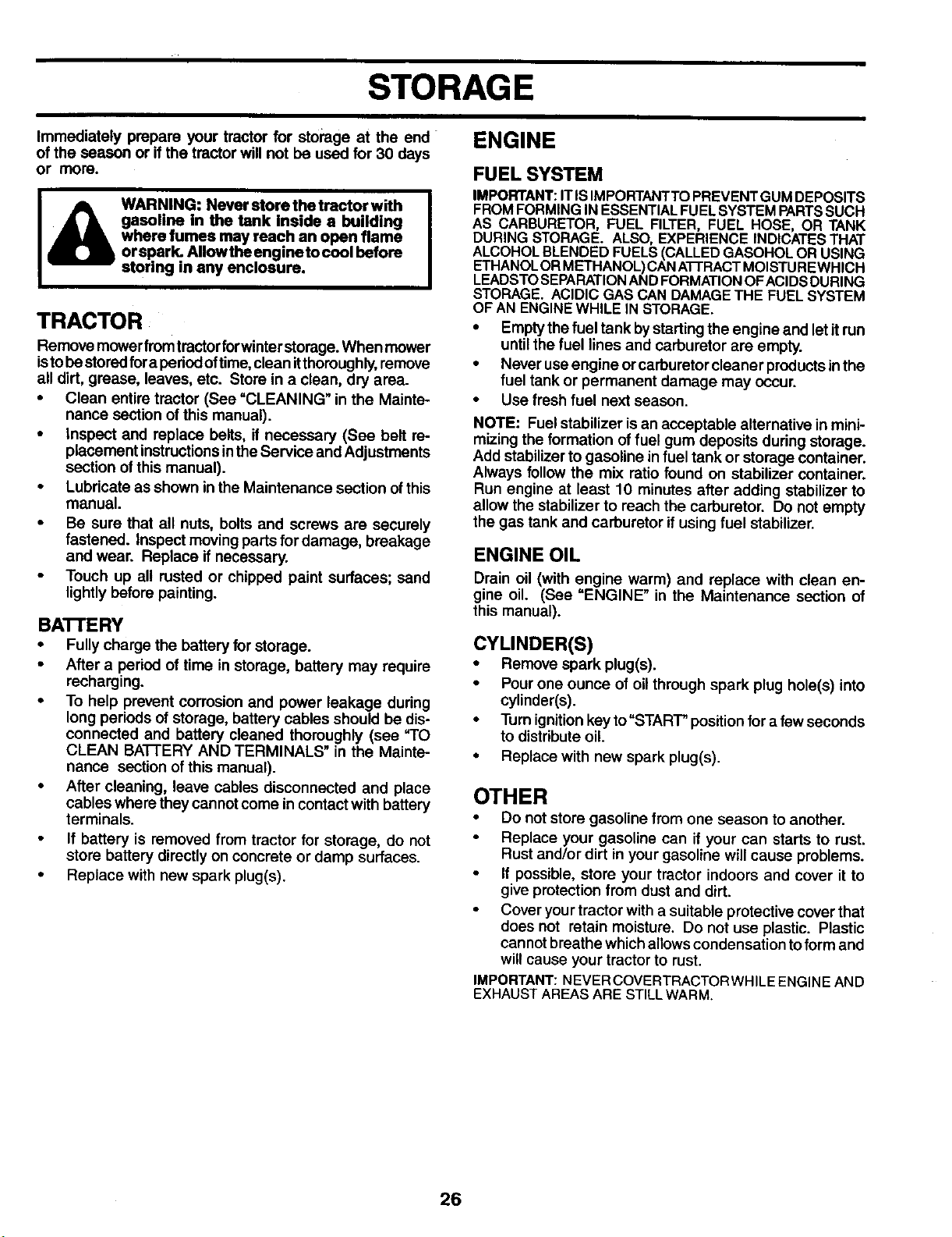
Immediately prepare your tractor for storage at the end
of the season or if the tractor will not be used for 30 days
or rnore.
WARNING: Never store the tractor with
gwhasolineIn the tank inside a building
ere fumes may reach an open flame
orspark. AIIowthe engineto cool before
storing in any enclosure.
TRACTOR
Remove mowerfrom tractorforwinter storage. When mower
istobestoredfor a periodoftime,clean itthoroughly,remove
all dirt, grease, leaves, etc. Store in a clean, dry area.
• Clean entire tractor (See =CLEANING" in the Mainte-
nance section of this manual).
• Inspect and replace belts, if necessary (See belt re-
placement instructionsinthe Service and Adjustments
section ofthis manual).
• Lubricate as shown inthe Maintenance section ofthis
manual.
• Be sure that all nuts, bolts and screws are securely
fastened. Inspect moving parts for damage, breakage
and wear. Replace if necessary.
• Touch up all rusted or chipped paint surfaces; sand
lightly before painting.
BATTERY
• Fully charge the battery for storage.
• After a period of time in storage, battery may require
recharging.
• To help prevent corrosion and power leakage during
long periods of storage, battery cables should be dis-
connected and battery cleaned thoroughly (see "TO
CLEAN BAI-i-ERY AND TERMINALS" in the Mainte-
nance section of this manual).
• After cleaning, leave cables disconnected and place
cables where they cannotcome in contact with battery
terminals.
• If battery is removed from tractor for storage, do not
store battery directly on concrete or damp surfaces.
• Replace with new spark plug(s).
FUEL SYSTEM
IMPORTANT:IT iSIMPORTANTTOPREVENTGUMDEPOSITS
FROMFORMINGIN ESSENTIALFUELSYSTEM PARTSSUCH
AS CARBURETOR, FUEL FILTER, FUEL HOSE, OR TANK
DURING STORAGE. ALSO, EXPERIENCE INDICATESTHAT
ALCOHOLBLENDEDFUELS(CALLEDGASOHOLOR USING
ETHANOLORMETHANOL)CANA-i-I'RACTMOISTUREWHiCH
LEADSTOSEPARATIONANDFORMATIONOFACIDSDURING
STORAGE. ACIDIC GASCAN DAMAGETHE FUEL SYSTEM
OF AN ENGINEWHILE IN STORAGE.
• Empty thefuel tank bystarting the engine and let itrun
until the fuel lines and carburetor are empty.
• Never useengine or carburetor cleaner preducts inthe
fuel tank or permanent damage may occur.
• Use fresh fuel next season.
NOTE: Fuel stabilizer is an acceptable alternative in mini-
mizing the formation of fuel gum deposits during storage.
Add stabilizer to gasoline in fuel tank or storage container.
Always follow the mix ratio found on stabilizer container.
Run engine at least 10 minutes after adding stabilizer to
allow the stabilizer to reach the carburetor. Do not empty
the gas tank and carburetor ifusing fuel stabilizer.
ENGINE OIL
Drain oil (with engine warm) and replace with clean en-
gine oil. (See "ENGINE" in the Maintenance section of
this manual).
CYLINDER(S)
• Remove spark plug(s).
• Pour one ounce of oilthrough spark plug hole(s) into
cylinder(s).
• Turn ignitionkey to"STARr" position for a few seconds
to distribute oil.
• Replace with new spark plug(s).
OTHER
• Do not store gasoline from one season to another.
• Replace your gasoline can if your can starts to rust.
Rust and/or dirt in your gasoline will cause problems.
If possible, store your tractor indoors and cover it to
give protection from dust and dirt.
• Cover yourtractor with a suitable protective cover that
does not retain moisture. Do not use plastic. Plastic
cannotbreathe whichallowscondensation toform and
willcause your tractor to rust.
IMPORTANT:NEVERCOVERTRACTORWHILEENGINEAND
EXHAUSTAREASARE STILLWARM.
26

PROBLEM
Will not start
Hard to start
Engine will not turn over
Engine clicks but will not
start
Loss of power
Excessive vibration
TROUBLESHOOTING POINTS
CAUSE
1. Out of fuel.
2. Engine not =CHOKED" properly.
3. Engine flooded.
4. Bad spark plug.
5. Dirty air filter.
6. Dirty fuel filter.
7. Water in fuel.
8. Looee ordamagedwidng.
9. Cerburetoroutofadjustment.
10. Engine valves out of adjustment.
1. Dirty air filter.
2. Bad spark plug.
3. Weak or dead battery.
4. Dirty fuel filter.
5. Stale or dirty fuel.
6. Loose or damaged wiring.
7. Carburetor out of adjustment.
8. Engine valves out of adjustment.
1. Brake pedal not depressed.
2. Attachment clutch is engaged.
3. Weak or dead battery.
4. Blown fuse.
5. Corroded battery terminals.
6. Loose or damaged wiring.
7. Faulty ignition switch.
8. Faulty solenoid or starter.
9. Faulty operator presence switch(ss).
1. Weak or dead battery.
2. Corroded battery terminals.
3. Loose or damaged wiring.
4. Faulty solenoid or starter.
1. Cutting too much grass/too fast,
2. Throttle in =CHOKE" position.
3. Build-up of grass, leaves and trash under mower.
4. Dirty air filter.
5. Low oil level/dirty oil.
6. Faulty spark plug.
7. Dirty fuel filter.
8. Stale or dirty fuel.
9. Water in fuel.
10. Spark plug wire loose.
11. Dirty engine air screen/fins.
12. Dirty/clogged muffler.
13. Loose or damaged wiring.
14. Carburetor out of adjustment.
15. Engine velves out of adjustment.
1. Worn, bent or loose blade.
2. Bent blade mandrel.
3. Loose/damaged part(s).
CORRECTION
1. Fill fuel tank.
2. See =TO START ENGINE" in Operafion section.
3. Wait severel minutes before attempting to start.
4. Replace spark plug.
5. ClearVreplacs air filter.
6, Replace fuel filter.
7, Empty fuel tank and carburetor, refill tank _ fresh
gasoline and replace fuel filter.
8. Chec_ all wiring.
9. See "To Adjust Carburetor" in Service Adjustments
section.
10. Contact an authorized service center/depar_nent.
1. Clean/replace air filter.
2. Replace spark plug.
3. Recharge or replace battery.
4. Replace fuel filter.
5. Empty fuel tank and refilltank withfresh, clean gasoline.
6. Check all wiring.
7. See =ToAdjust Carburetor" in Service Adjus'bmente
section.
8. Contact an authodzed service center/department.
1. Depress brake pedal.
2. Disengage attachment clutch.
3. Recharge or replace battery.
4. Replace fuse.
5. Clean battery terminals.
6. Check all widng.
7. Check/replace ignition switch.
8. Check/replace solenoid or starter.
9. Contact an authorized service centar/deparlment.
1, Recharge or replace battery.
2. Clean battery terminals.
3. Check all wiring.
4. Checldreplacs solenoid or starter,
1. Raise cuffing height/reduce speed.
2. Adjust throttle control.
3. Clean underside of mower housing.
4. Clean/replace air filter.
5. Check oil level/change oil.
6. Clean and regap or change spark plug.
7. Replace fuel filter.
8. Empty fuel tank and refilltank withfresh, clean gasoline.
9. Empty fuel tank and carburetor, refill tank with fresh
gasoline and replace fuel filter.
10. Connect and tighten spark plug wire.
11. Clean engine air screen/fins.
12. Clean/replace muffler.
13. Check all widng.
14. See "To Adjust Carburetor" in Sen, ice Adjustments
section.
15. Contact an authorized service center/department.
1. Replace blade. Tighten blade bolt.
2. Replace blade mandrel.
3. Tighten loose part(s). Replace damaged parts.
27
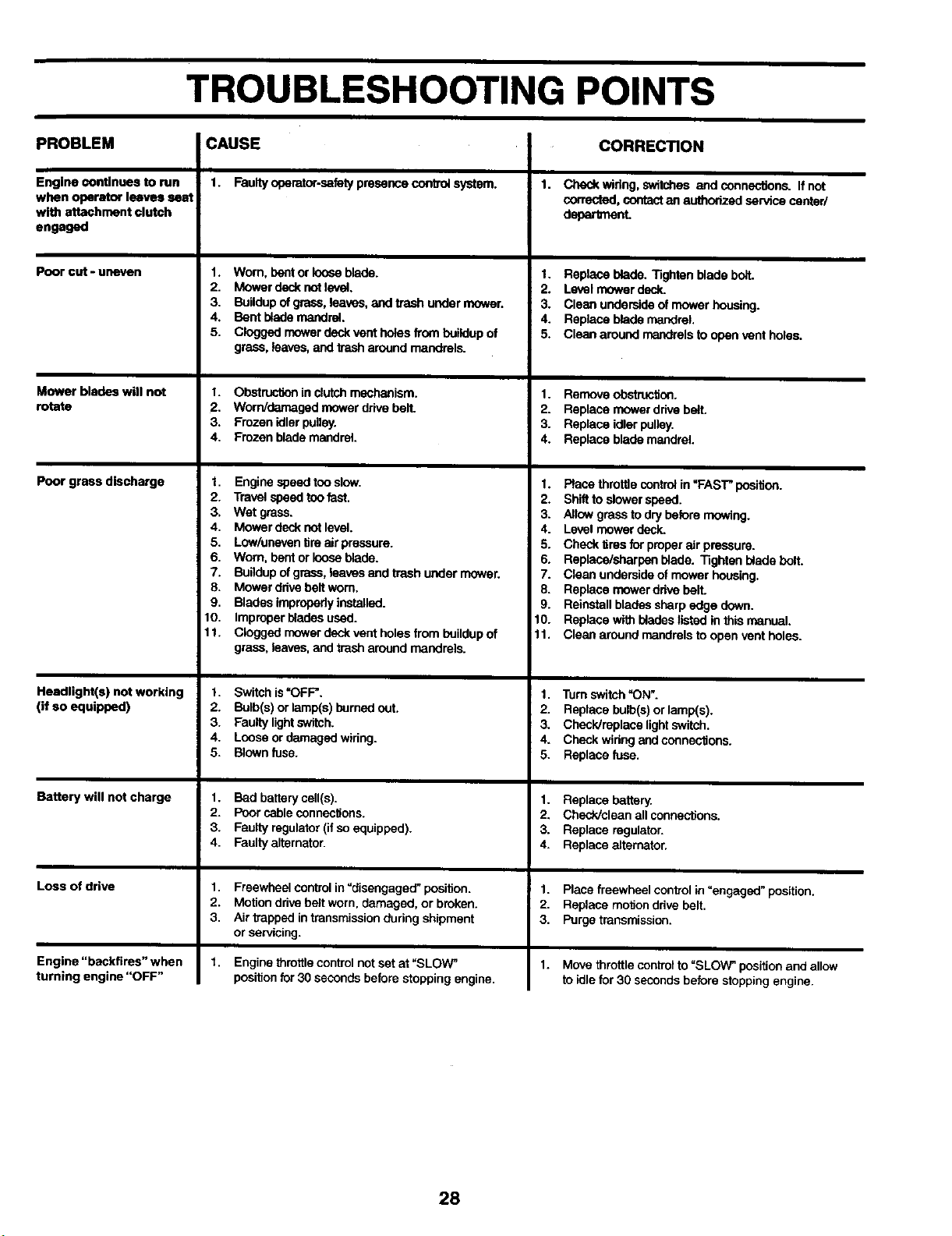
TROUBLESHOOTING POINTS
PROBLEM CAUSE CORRECTION
Engine continues to run
when operator leaves seat
with attachment clutch
engaged
Poor cut - uneven
Mower blades will not
rotate
Poor grass discharge
Headlight(s) not working
(if so equipped)
Battery will not charge
Loss of drive
Engine "backfires" when
turning engine "OFF"
1. Faulty operator-safety presence contro_ system.
1. Worn, bent or loose blade.
2. Mower deck not level.
3. Buildup of grass, leaves, and trash under mower.
4. Bent blade mandrel.
5. Clogged mower deck vent holes from buildup of
grass, leaves, and trash around mandrels.
1. Obstruction in clutch mechanism.
2. Worn/damaged mower drive belt.
3. Frozen idler pulley.
4. Frozen blade mandrel
1. Engine speed too slow.
2. Travel spsed too fast.
3, Wet grass.
4. Mower deck not level.
5. Low/uneven tim air pressure.
6. Worn, bent or loose blade.
7_ Buildup of grass, leaves and trash under mower.
8. Mower drive belt worn.
9. Blades impropedy installed.
10. Improper blades used.
11. Clogged mower deck vent holes from buildup of
grass, leaves, and trash around mandrels.
1. Switch is"OFF".
2. Bulb(s) or lamp(s) burned out,
3. Faulty lightswitch.
4. Louse or damaged wiring.
5. Blown fuse.
1. Bed bakery cell(s).
2. Poor cable connections.
3. Faulty regulator (if so equipped).
4. Faulty alternator.
1. Freewheel control in =disengaged" position.
2. Motion drive belt worn, damaged, or broken.
3. Air trapped in transmission during shipment
or servicing.
Engine throttle control not set at "SLOV_'
position for 30 seconds before stopping engine.
1.
Check wiflog, switches and connecttons_ If not
corrected, contact an authorized service center/
debarlment.
1. Replace blade. Tighten blade bo_t.
2. Level mower deck.
3. Clean underside of mower housing.
4. Replace blade mandrel,
5. Clean around mandrels to open vent holes.
1. Remove obstruction.
2. Replace mower drive belt.
3. Replace idler pulley.
4. Replace blade mandrel.
1. Place throttle control in =FAST" position.
2. Shift to slower speed.
3. Allow grass to dry betom mowing.
4. Level mower deck.
5. Check tires for proper air pressure.
6. Repisce/sharpen blade. Tighten blade bolt.
7. Clean underside of mower housing.
8. Replace mower drive belt.
9. Reinstall blades sharp edge down.
10. Replace with blades listed in this manual.
11. Clean around mandrels to open vent holes.
1. Turn switch "ON'.
2. Replace bulb(s) or lamp(s).
3. Check/replace light switch.
4. Check widog and connec'dons.
5. Replace fuse.
1. Replace battery.
2. ChecPJclean all connections.
3. Replace regulator.
4. Replace alternator.
1. Place freewheel control in "engaged" position.
2. Replace mol_on drive belt.
3. Purge transmission.
1.
Move throttle control to =SLOW_position and allow
to idle for 30 seconds before stopping engine.
28
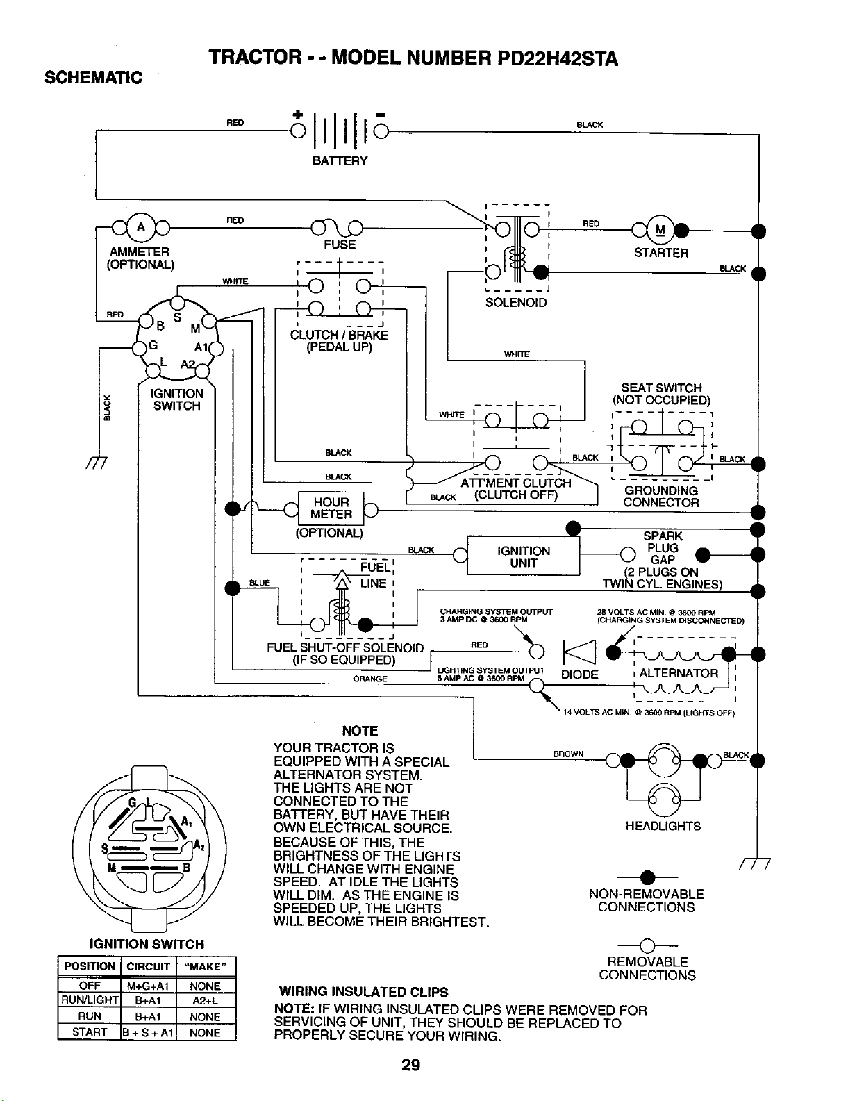
SCHEMATIC
TRACTOR - - MODEL NUMBER PD22H42STA
)
)G A1
IGNITION
SWITCH
BATTERY
RED
FUSE
BLACK
BLAC_
HOUR
METER
I I
RED
STARTER
I _arm
SEATSWITCH
=.... = I(NOTOCCUPIED)
__WHITE II _ _ " 711........__-'11
f ........ ',
CONNECTOR
LINE
J
FUELSHUT-OFFSOLENOID
(IF SO EQUIPPED)
ORANGE
SPARK
BLACK(_ IGNITION _ PLUG LUNIT I "J GAP
I (2 PLUGSON
RED TWINICYL,ENGINES) J
CHARGING SYSTEM OUTPUT 28 VOLTS AC MIN, O 3600 RPM
3 AMP DC @ 3600 RPM (CHARGING SYSTEM DISCONNECI1ED)
J LIGHTING SYSTEM OUTPUT I
--14 VOLTS AC M,N. RPM (LIGHTS OFF)
IGNITION SWITCH
PosmoN CIRCUIT I
OFF M+G+A1
RUN/LIGHT B+A1
RUN B+A1
START 3+S+A1
"MAKE"
NONE
A2+L
NONE
NONE
NOTE
YOUR TRACTOR IS
EQUIPPED WITH A SPECIAL
ALTERNATOR SYSTEM.
THE LIGHTS ARE NOT
CONNECTED TO THE
BATTERY, BUT HAVE THEIR
OWN ELECTRICAL SOURCE.
BECAUSE OF THIS, THE
BRIGHTNESS OF THE LIGHTS
WILL CHANGE WITH ENGINE
SPEED. AT IDLE THE LIGHTS
WILL DIM. AS THE ENGINE IS
SPEEDED UP, THE LIGHTS
WILL BECOME THEIR BRIGHTEST.
BROWN
HEADLIGHTS
/7
NON-REMOVABLE
CONNECTIONS
©
REMOVABLE
CONNECTIONS
WIRING INSULATED CLIPS
NOTE: IF WIRING INSULATED CLIPS WERE REMOVED FOR
SERVICING OF UNIT, THEY SHOULD BE REPLACED TO
PROPERLY SECURE YOUR WIRING.
)
29
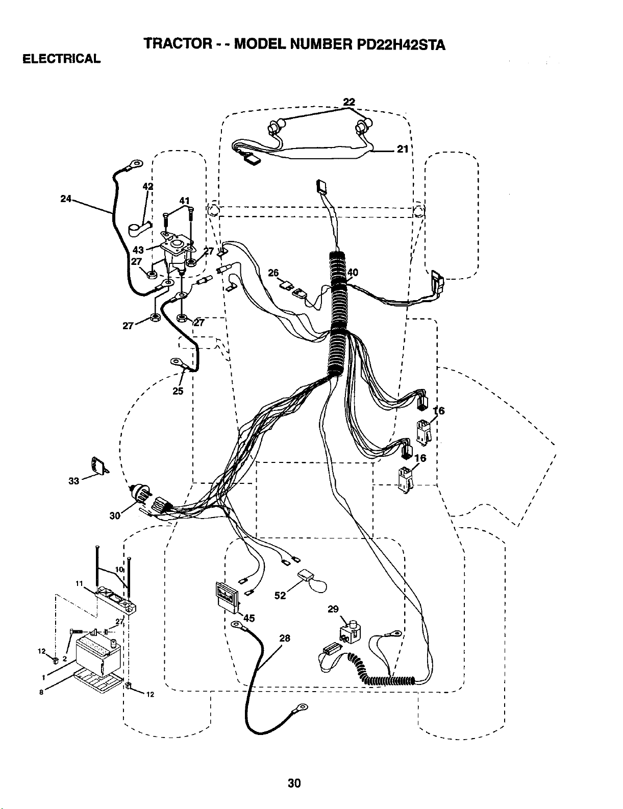
ELECTRICAL
TRACTOR - - MODEL NUMBER PD22H42STA
22
26
%
%
%
%
I
I
I
I
l
I
I
I
I
3O
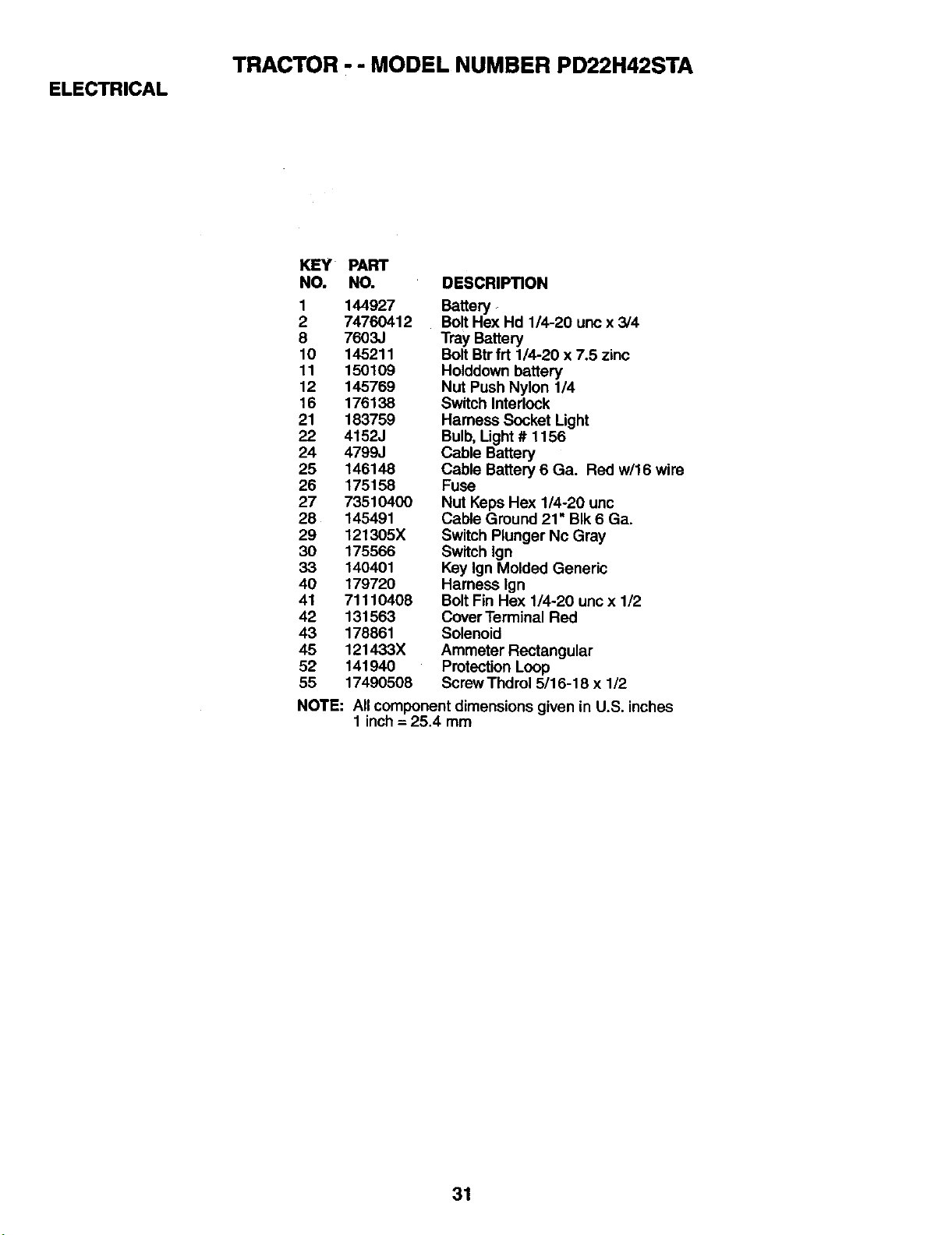
ELECTRICAL
TRACTOR - - MODEL NUMBER PD22H42STA
KEY PART
NO. NO. DESCRIPTION
1 144927
2 74760412
8 7603J
10 145211
11 150109
12 145769
16 176138
21 183759
22 4152J
24 4799J
25 146148
26 175158
27 73510400
28 145491
29 121305X
30 175566
33 140401
40 179720
41 71110408
42 131563
43 178861
45 121433X
52 141940
55 17490508
Battery
Bolt Hex Hd 1/4-20 unc x 3/4
Tray Battery
Bolt Btrfrt 1/4-20 x 7.5 zinc
Holddown battery
Nut Push Nylon 1/4
Switch Interlock
Harness Socket Light
Bulb, Light # 1156
Cable Battery
Cable Battery 6 Ga. Red w/16 wire
Fuse
Nut Keps Hex 1/4-20 unc
Cable Ground 21" BIk 6 Ga.
Switch Plunger Nc Gray
Switch Ign
Key Ign Molded Generic
Harness lgn
Bolt Fin Hex 1/4-20 uricx 1/2
Cover Terminal Red
Solenoid
Ammeter Rectangular
ProtectionLoop
ScrewThdrol5/15-16x I/2
NOTE: All component dimensions given in U.S. inches
1 inch= 25.4 mm
31
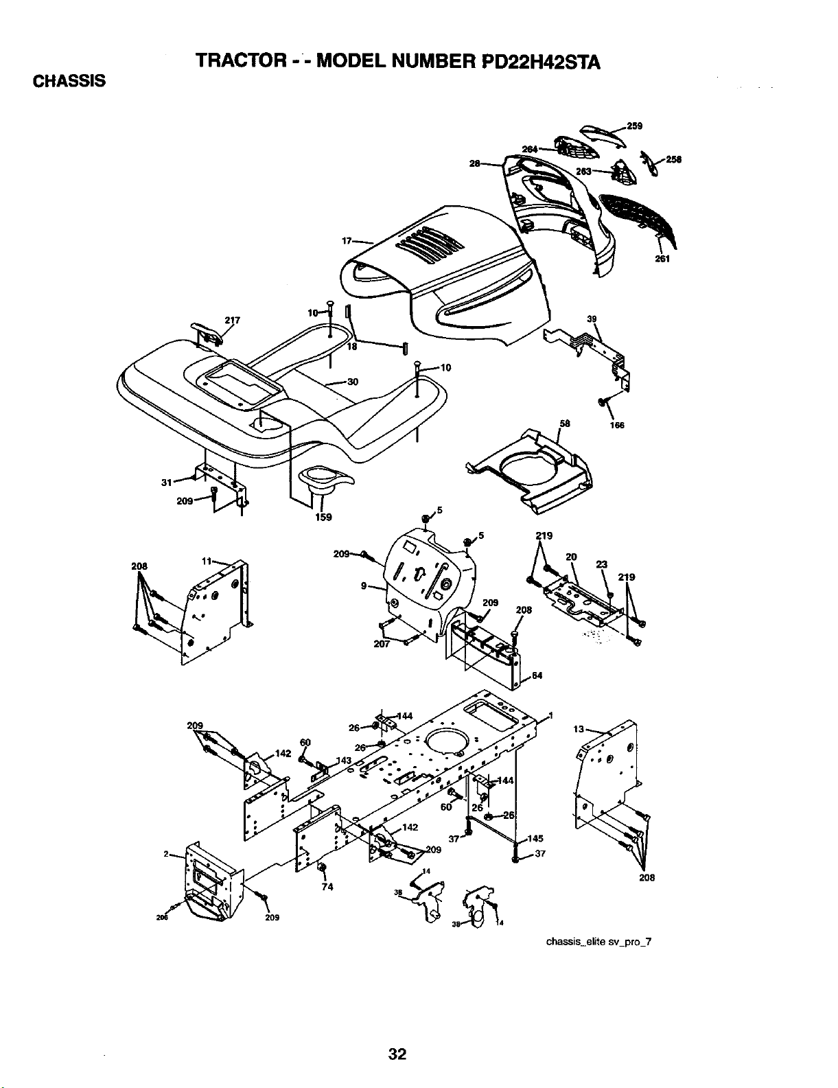
CHASSIS
TRACTOR - - MODEL NUMBER PD22H42STA
261
39
2O8
58
166
219
2O9
,145
209
74
2O8
chassis_elite sv_pro_7
32
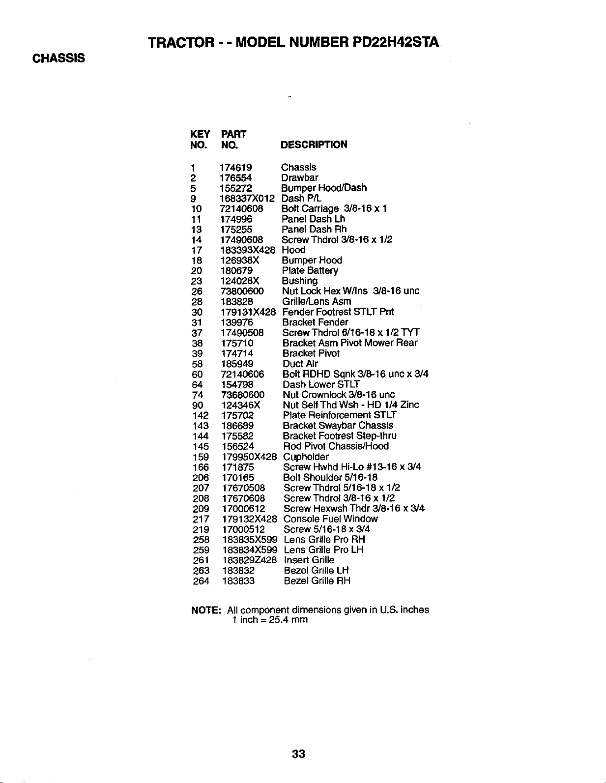
CHASSIS
TRACTOR - - MODEL NUMBER PD22H42STA
KEY PART
NO. NO, DESCRIPTION
1 174619
2 176554
5 155272
9 168337X012
10 72140608
11 174996
13 175255
14 17490608
17 183393X428
18 126938X
20 180679
23 124028X
26 73800600
28 183828
30 179131X428
31 139976
37 17490508
38 175710
39 174714
58 185949
60 72140606
64 154798
74 7368060O
90 124346X
142 175702
143 186689
144 175582
145 156524
159 179950X428
166 171875
2O6 170165
207 17670508
208 17670608
209 17000612
217 179132X428
219 17000512
258 183835X599
259 183834X599
261 183829Z428
263 183832
264 183833
Chassis
Drawbar
Bumper Hood/Dash
Dash P/L
Bolt Carriage 3/6-16 x 1
Panel Dash Lh
Panel Dash Rh
Screw Thdrol 3/8-16 x 1/2
Hood
Bumper Hood
Plate Battery
Bushing
Nut Lock HexW/Ins 3/8-16 unc
Grille/Lens Asm
Fender Footrest STLT Pnt
Bracket Fender
Screw Thdrol 6/16-18 x 1/2 TYT
Bracket Asm Pivot Mower Rear
Bracket Pivot
Duct Air
Bolt RDHD Sqnk 3/8-16 unc x 3/4
Dash Lower STLT
Nut Crownlock 3/8-16 unc
Nut Self Thd Wsh - HD 1/4 Zinc
Plate Reinforcement STLT
Bracket Swaybar Chassis
Bracket Footrest Step-thru
Rod Pivot Chassis/Hood
Cupholder
Screw Hwhd Hi-Lo #13-16 x 3/4
Bolt Shoulder 5/16-18
Screw Thdrol 5/16-18 x 1/2
Screw Thdrol 3/6-16 x 1/2
Screw Hexwsh Thdr 3/8-16 x 3/4
Console Fuel Window
Screw 5/16-18 x 3/4
Lens Grille Pro RH
Lens Grille Pro LH
Insert Grille
Bezel Grille LH
Bezel Grille RH
NOTE: All component dimensions given in U.S. inches
1 inch = 25.4 mm
33
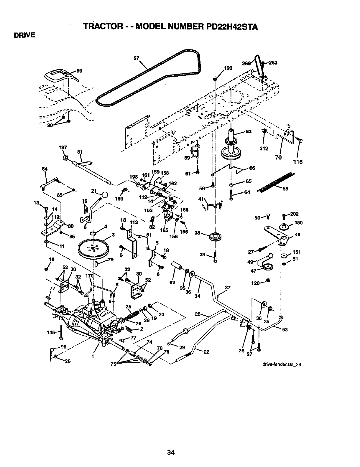
DRIVE
TRACTOR. - MODEL NUMBER PD22H42STA
26
27
dfive-fender.sttt 29
34
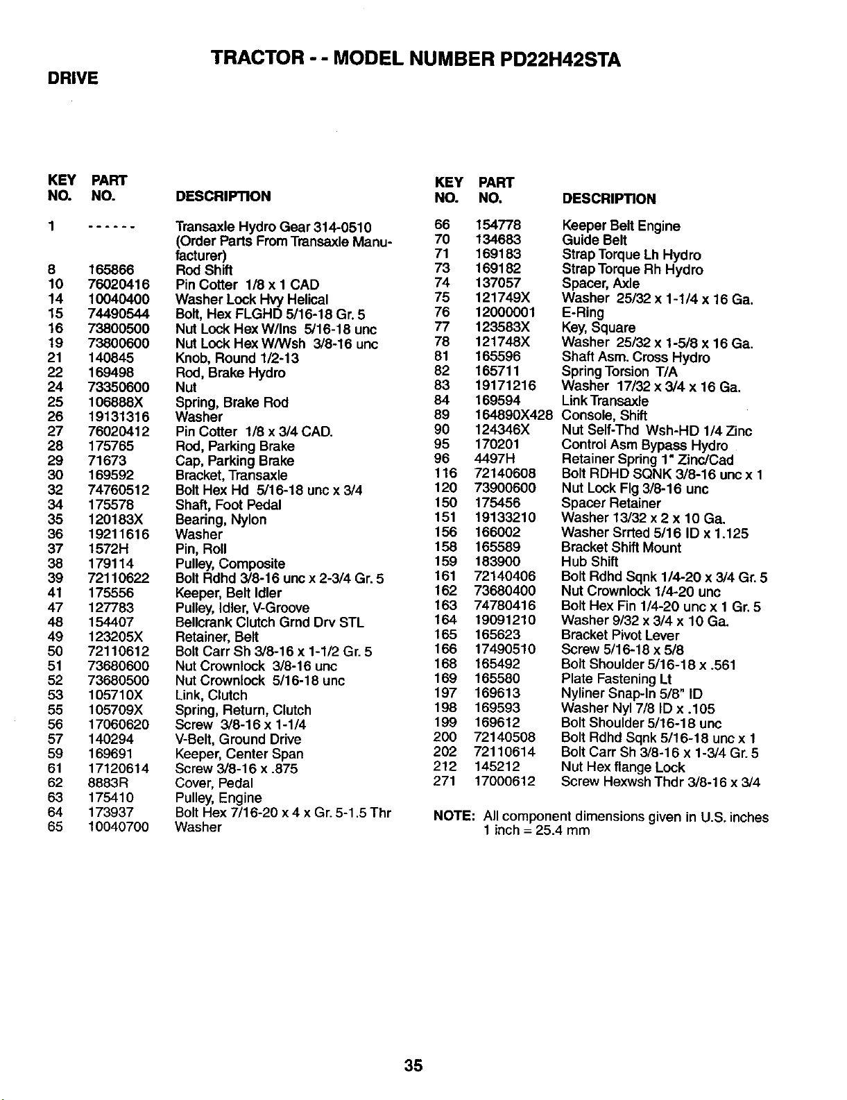
DRIVE
TRACTOR - - MODEL NUMBER PD22H42STA
KEY
NO.
8
10
14
15
16
19
21
22
24
25
26
27
28
29
30
32
34
35
36
37
38
39
41
47
48
49
50
51
52
53
55
56
57
59
61
62
63
64
65
PART
NO.
165866
76020416
10040400
74490544
73800500
73800600
14O845
169498
73350600
106888X
19131316
76020412
175765
71673
169592
74760512
175578
120183X
19211616
1572H
179114
72110622
175556
127783
154407
123205X
72110612
73680600
73680500
105710X
105709X
17060620
140294
169691
17120614
8883R
175410
173937
10040700
KEY PART
DESCRIPTION NO. NO. DESCRIPTION
Transaxle Hydro Gear 314-0510 66 134778
(Order Parts FromTransaxle Manu- 70 134683
facturer) 71 169183
Rod Shift 73 169182
Pin Cotter 1/8xl CAD 74 137057
Washer Lock Hvy Helical 75 121749X
Bolt, Hex FLGHD 5116-18 Gr. 5 76 12000001
Nut Lock Hex W/Ins 5/16.18 unc 77 123583X
Nut Lock Hex W/Wsh 3/8-16 unc 78 121748X
Knob, Round 1/2-13 81 165596
Rod, Brake Hydro 82 165711
Nut 83 19171216
Spring, Brake Rod 84 169594
Washer 89
Pin Cotter 1/8 x 3/4 CAD. 90 124346X
ROd,Parking Brake 95 170201
Cap, Parking Brake 96 4497H
Bracket, Transaxle 116 72140608
Bolt Hex Hd 5/16-18 unc x 3/4 120 73900600
Shaft, Foot Pedal 150 175456
Bearing, Nylon 151 19133210
Washer 156 166002
Pin, Roll 158 165589
Pulley, Composite 159 183900
Bolt Rdhd 3/8-16 unc x 2-3/4 Gr. 5 161 72140406
Keeper, Belt Idler 162 73680400
Pulley, Idler, V-Groove 163 74780416
Bellcrank Clutch Grnd Drv STL 164 19091210
Retainer, Belt 165 165623
Bolt Carr Sh 3/8-16 x 1-1/2 Gr. 5 166 17490510
Nut Crownlock 3/8-16 uric 168 165492
Nut Crownlock 5/16-18 unc 169 165580
Link, Clutch 197 169613
Spring, Return, Clutch 198 169593
Screw 3/8-16x1-1/4 199 169612
V-Belt, Ground Drive 200 72140508
Keeper, Center Span 202 72110614
Screw 3/8-16 x .875 212 145212
Cover, Pedal 271 17000612
Pulley, Engine
Bolt Hex 7/16-20 x 4 x Gr. 5-1.5 Thr
Washer
Keeper Belt Engine
Guide Belt
Strap Torque Lh Hydro
Strap Torque Rh Hydro
Spacer, Axle
Washer 25/32 x 1-1/4 x 16 Ga.
E-Ring
Key, Square
Washer 25132 x 1-5/8 x 16 Ga.
Shaft Asm. Cross Hydro
Spring Torsion T/A
Washer 17/32 x 3/4 x 16 Ga.
Link Transaxle
164890X428 Console, Shift
Nut Self-Thd Wsh-HD 1/4 Zinc
Control Asm Bypass Hydro
Retainer Spring 1"Zinc/Cad
Bolt RDHD SQNK 3/8-16 unc x 1
Nut Lock Fig 3/8-16 unc
Spacer Retainer
Washer 13/32 x 2 x 10 Ga.
Washer Srrted 5/16 ID x 1.125
Bracket Shift Mount
Hub Shift
Bolt Rdhd Sqnk 1/4-20 x 3/4 Gr. 5
Nut Crownlock 1/4-20 unc
Bolt Hex Fin 1/4-20 unc x 1 Gr. 5
Washer 9/32 x 3/4 x 10 Ga.
Bracket Pivot Lever
Screw 5/16-18 x 5/8
Bolt Shoulder 5/16-18 x .561
Plate Fastening Lt
Nyliner Snap-In 5/8" ID
Washer Nyl 7/8 ID x .105
Bolt Shoulder 5/16-18 unc
Bolt Rdhd Sqnk 5/16-18 unc x 1
Bolt Carr Sh 3/8-16 x 1-3/4 Gr. 5
Nut Hex flange Lock
Screw Hexwsh Thdr 3/8-16 x 3/4
NOTE: All component dimensions given in U.S. inches
1 inch = 25.4 mm
35
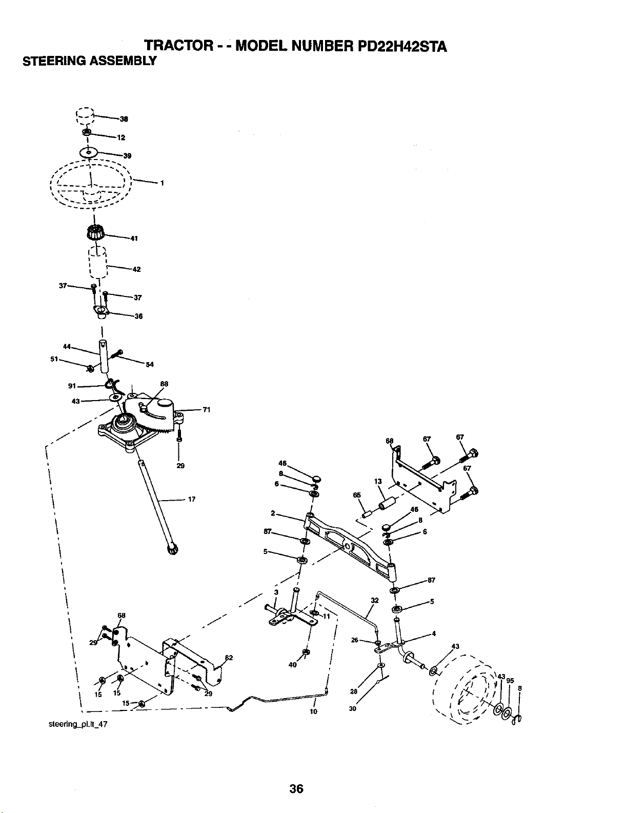
TRACTOR - ' MODEL NUMBER PD22H42STA
STEERING ASSEMBLY
sis i _ ...
/l_'J _ "\ \1
•i_
_41
I I
I
37
36
29
68 67 67
67
48
6_ 65 13
36
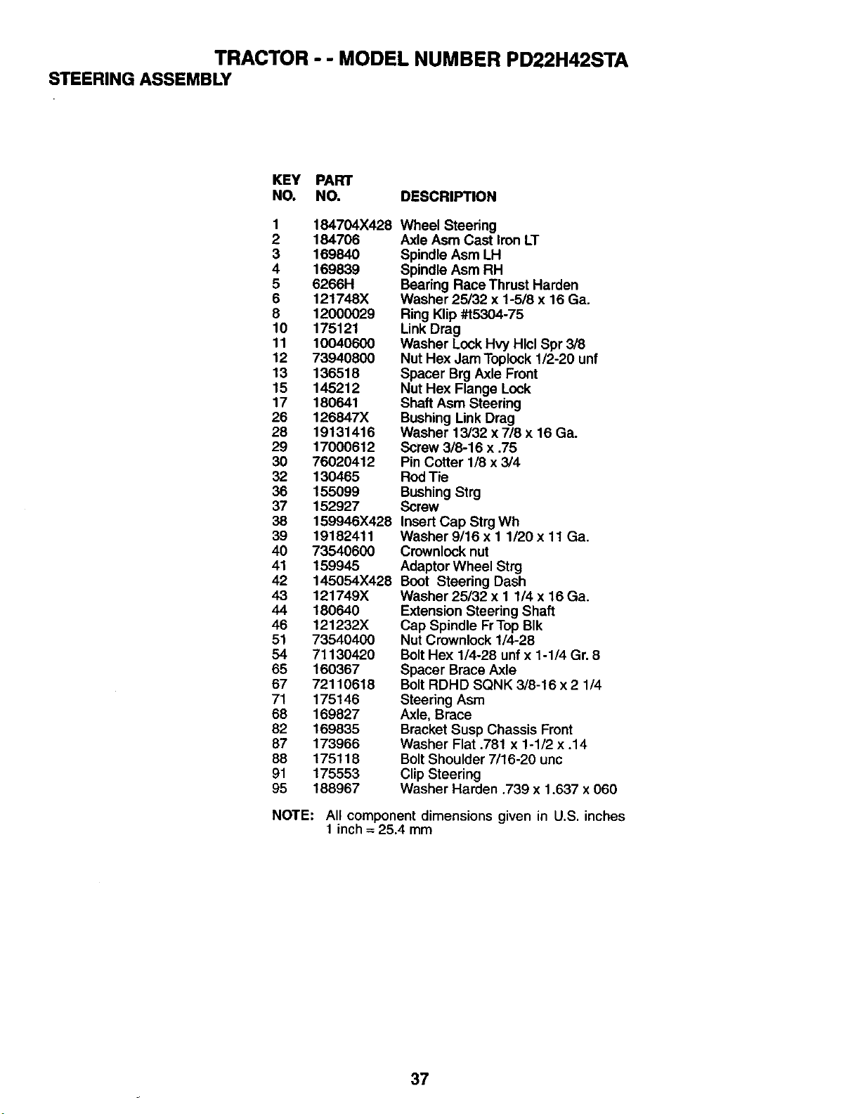
TRACTOR - - MODEL NUMBER PD22H42STA
STEERING ASSEMBLY
KEY PART
NO. NO. DESCRIPTION
1 184704X428
2 184706
3 169840
4 169839
5 6266H
6 121748X
8 12000029
10 175121
11 10040600
12 73940800
13 136518
15 145212
17 180641
26 126847X
28 19131416
29 17000612
30 76020412
32 130465
36 155099
37 152927
38 159946X428
39 19182411
40 73540600
41 159945
42 145054X428
43 121749X
44 180640
46 121232X
51 73540400
54 71130420
65 160367
67 72110618
71 175146
68 169827
82 169835
87 173966
88 175118
91 175553
95 188967
Wheel Steering
Axle Asm Cast Iron LT
Spindle Asm LH
Spindle Asm RH
Bearing Race Thrust Harden
Washer 25/32 x 1-5/8 x 16 Ga.
Ring Klip #t5304-75
Link Drag
Washer Lock Hvy Hlcl Spr 3/8
Nut Hex Jam Toplock 1/2-20 unf
Spacer Brg Axle Front
Nut Hex Flange Lock
Shaft Asm Steering
Bushing Link Drag
Washer 13/32 x 7/8 x 16 Ga.
Screw 3/8-16 x .75
Pin Cotter 1/8 x 3/4
RodTie
Bushing Strg
Screw
Insert Cap Strg Wh
Washer 9/16 x 1 1/20x 11 Ga.
Crownlock nut
Adaptor Wheel Strg
Boot Steering Dash
Washer 25/32 x 1 1/4 x 16 Ga.
Extension Steering Shaft
Cap Spindle FrTop BIk
Nut Crownlock 1/4-28
BoltHex 1/4-28 unf x 1-1/4 Gr. 8
Spacer Brace Axle
Bolt RDHD SQNK 3/8-16 x 2 1/4
Steering Asm
Axle, Brace
Bracket Susp Chassis Front
Washer Flat .781 x 1-1/2 x .14
BoltShoulder 7/16-20 unc
Clip Steering
Washer Harden ,739 x 1.637 x 060
NOTE: All component dimensions given in U.S. inches
1 inch= 25.4 mm
37
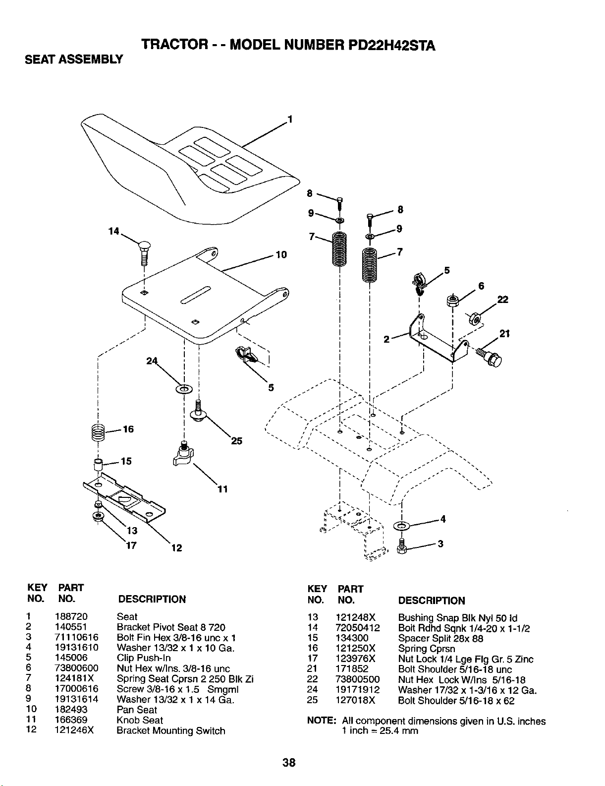
TRACTOR - - MODEL NUMBER PD22H42STA
SEAT ASSEMBLY
,%
I
I
17 12
25
I
i
I
5
21
KEY
NO.
1
2
3
4
5
6
7
8
9
10
11
12
PART
NO.
188720
140551
71110616
19131610
145006
73800600
124181X
17000616
19131614
182493
166369
121246X
DESCRIPTION
Seat
Bracket Pivot Seat 8 720
Bolt Fin Hex 3/8-16 unc x 1
Washer 13/32 x 1 x 10 Ga.
Clip Push-In
Nut Hex w/Ins. 3/8-16 uric
Spring Seat Cprsn 2 250 BIk Zi
Screw 3/8-16 x 1.5 Smgml
Washer 13/32 x 1 x 14 Ga.
Pan Seat
Knob Seat
Bracket Mounting Switch
KEY PART
NO. NO. DESCRIPTION
13 121248X
14 72050412
15 134300
16 121250X
17 123976X
21 171852
22 73800500
24 19171912
25 127018X
Bushing Snap BIk Nyl 50 Id
Bolt Rdhd Sqnk 1/4-20 x 1-1/2
Spacer Split 28x 88
Spring Cprsn
Nut Lock 1/4 Lge Fig Gr. 5 Zinc
Bolt Shoulder 5/16-18 unc
Nut Hex LockW/Ins 5/16-18
Washer 17/32 x 1-3/16 x 12 Ga.
Bolt Shoulder 5/16-18 x 62
NOTE: All component dimensions given in U.S. inches
1 inch = 25.4 mm
38
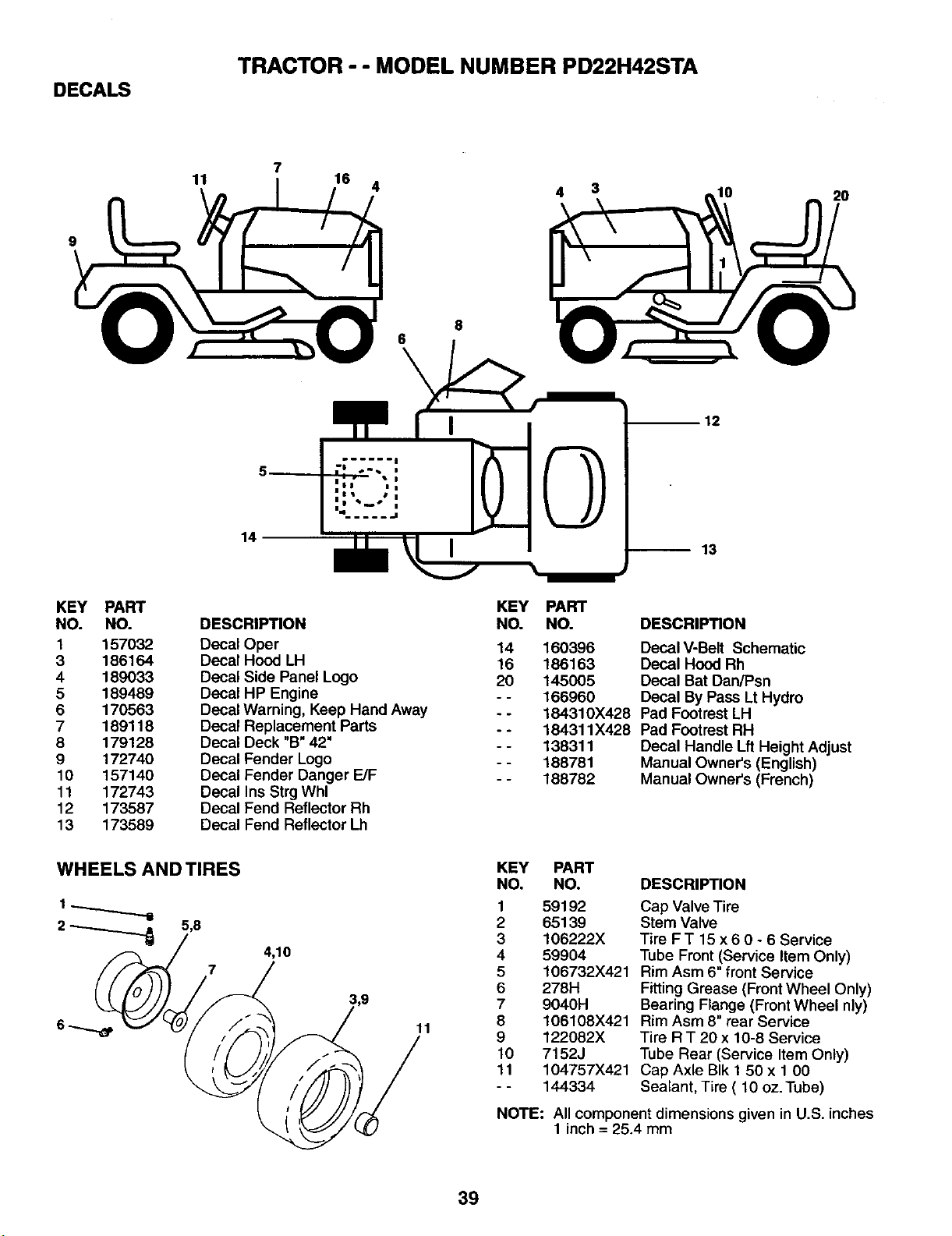
DECALS
TRACTOR - - MODEL NUMBER PD22H42STA
11
16 4
10 2O
9
8
6
14
I
I| | |
|t I I
12
13
KEY PART
NO. NO.
1 157032
8 188164
4 189033
5 189489
6 170563
7 189118
8 179128
9 172740
10 157140
11 172743
12 173587
13 173589
DESCRIPTION
Decal Oper
Decal Hood LH
Decal Side Panel Logo
Decal HP Engine
Decal Warning, Keep Hand Away
Decal Replacement Parts
Decal Deck "B" 42"
Decal Fender Logo
Decal Fender Danger E/F
Decal Ins Strg Whl
Decal Fend Reflector Rh
Decal Fend Reflector Lh
WHEELS AND TIRES
2 _ 5,8
4,10
11
KEY PART
NO. NO.
14 160396
16 186163
20 145005
- - 166960
- - 184310X428
- - 184311X428
- - 138311
- - 188781
- - 188782
DESCRIPTION
Decal V-Belt Schematic
Decal Hood Rh
Decal Bat DaniPsn
Decal By Pass Lt Hydro
Pad Footrest LH
Pad Footrest RH
Decal Handle Lft Height Adjust
Manual Owner's (English)
Manual Owner's (French)
KEY PART
NO, NO. DESCRIPTION
1 59192
2 65139
3 106222X
4 59904
5 106732X421
6 278H
7 9040H
8 106108X421
9 122082X
10 7152J
11 104757X421
- - 144334
Cap Valve Tire
Stem Valve
Tire F T 15 x 6 0 - 6 Service
Tube Front (Service item Only)
Rim Asm 6" front Service
Fitting Grease (Front Wheel Only)
Bearing Flange (Front Wheel nly)
Rim Asm 8" rear Service
Tire RT 20x 10-8 Service
Tube Rear (Service Item Only)
Cap Axle BIk 1 50 x 1 00
Sealant, Tire ( 10 oz.Tube)
NOTE: All component dimensions given in U.S. inches
1 inch = 25.4 mm
39
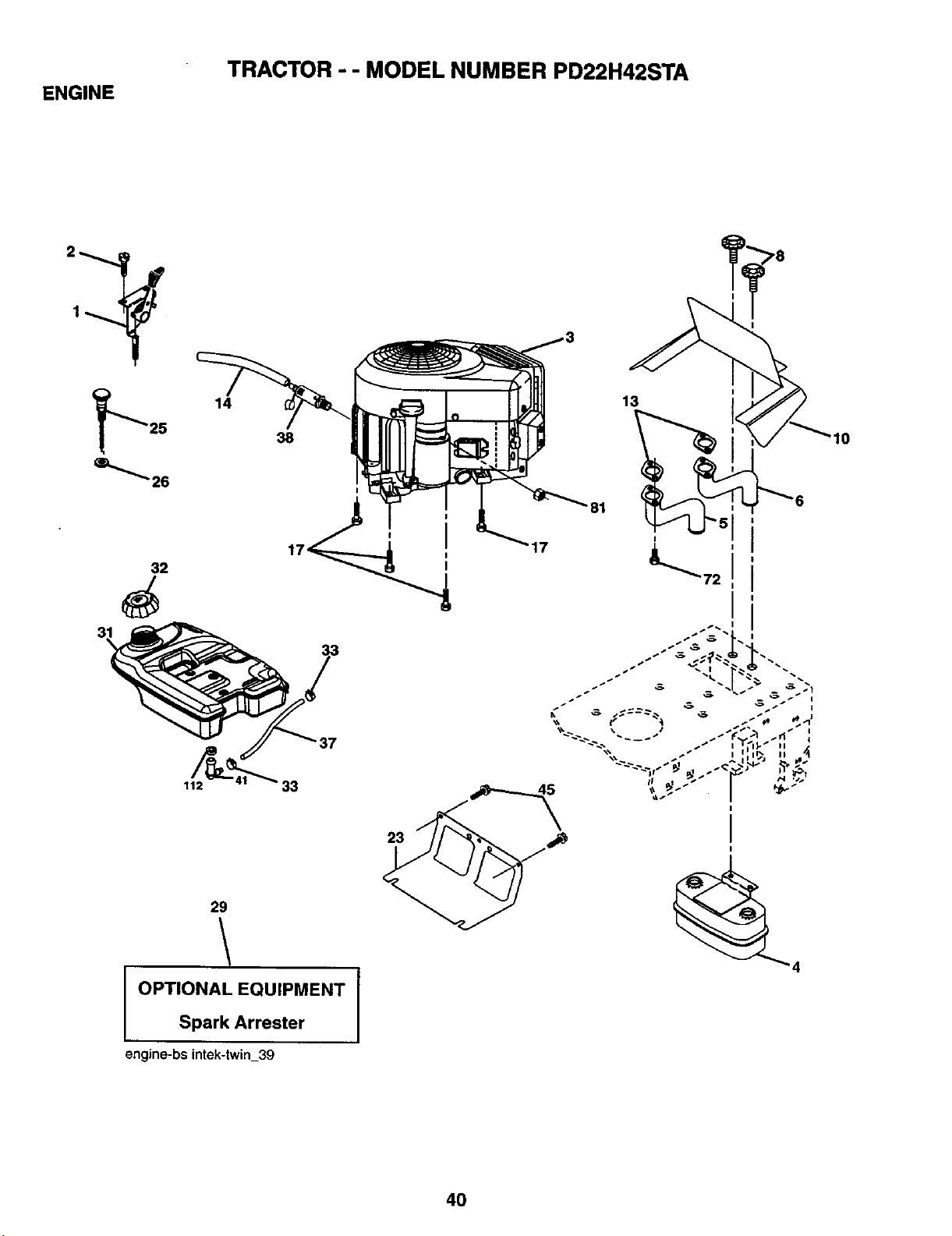
ENGINE
TRACTOR - - MODEL NUMBER PD22H42STA
2_
14 13
38
29
23
OPTIONAL EQUIPMENT
Spark Arrester
engine-bs intek-twin_S9
10
40
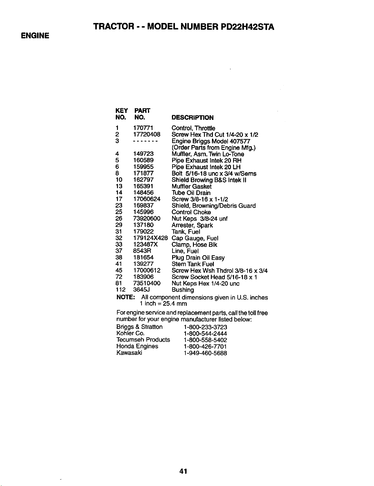
ENGINE
TRACTOR - - MODEL NUMBER PD22H42STA
KEY PART
NO. NO. DESCRIPTION
1
2
3
170771
17720408
4 149723
5 160589
6 159955
8 171877
10 162797
13 165391
14 148456
17 17060624
23 169837
25 145996
26 73920600
29 137180
31 179022
32 179124X428
33 123487X
37 8543R
38 181654
41 139277
45 17000612
72 183906
81 73510400
112 3645,.I
Control, Throttle
Screw Hex Thd Cut 1/4-20 x 1/2
Engine Briggs Model 407577
(Order Parts from Engine Mfg.)
Muffler, Asm. Twin Lo-Tone
Pipe Exhaust Intek 20 RH
Pipe Exhaust Intek 20 LH
Bolt 5/16-18 unc x 3/4 w/Sems
Shield Browing B&S Intek II
Muffler Gasket
Tube Oil Drain
Screw 3/8-16 x 1-1/2
Shield, Brewning/Debris Guard
Control Choke
Nut Keps 3/8-24 unf
Arrester, Spark
Tank, Fuel
Cap Gauge, Fuel
Clamp, Hose BIk
Line, Fuel
Plug Drain Oil Easy
Stem Tank Fuel
Screw Hex Wsh Thdrol 3/8-16 x 3/4
Screw Socket Head 5/16-18 x 1
Nut Keps Hex 1/4-20 unc
Bushing
NOTE: All component dimensions given in U.S. inches
1 inch -- 25.4 mm
For engine service and replacement parts, call the toll free
number for your engine manufacturer listed below:
Briggs & Stratton 1-800-233-3723
Kohler Co. 1-800-544-2444
Tecumseh Products 1-800-558-5402
Honda Engines 1-800-426-7701
Kawasaki 1-949-460-5688
41
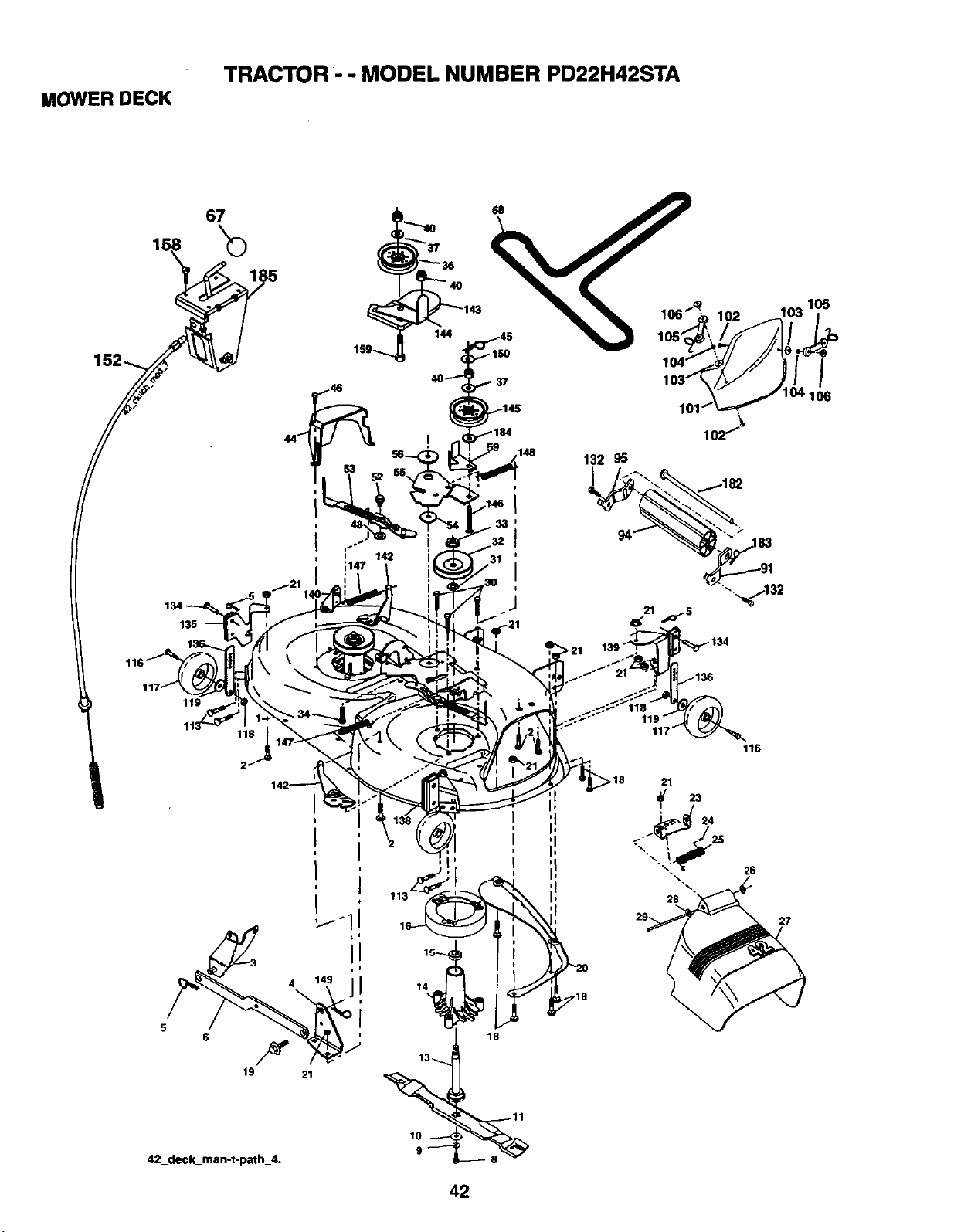
MOWER DECK
TRACTOR- - MODEL NUMBER PD22H42STA
67
152_ 5
/
;147
> 21
_134
1t9
L
42_deck_man-t-path_4.
14
18
28
116
26
27
42
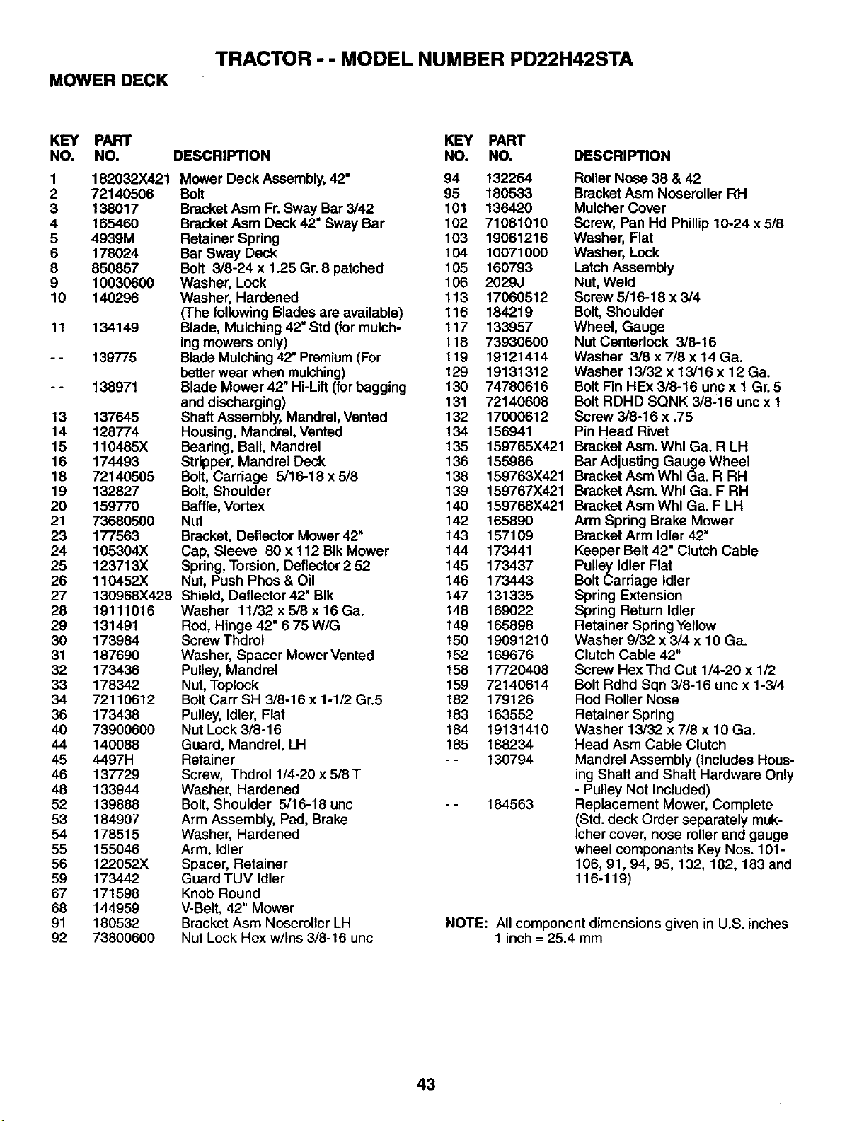
MOWER DECK
TRACTOR - - MODEL NUMBER PD22H42STA
KEY PART
NO. NO. DESCRIPTION
1 182032X421
2 72140506
3 138017
4 165460
5 4939M
6 178024
8 850857
9 10030600
10 140296
11 134149
139775
138971
13 137645
14 128774
15 110485X
16 174493
18 72140505
19 132827
20 159770
21 73680500
23 177563
24 105304X
25 123713X
26 110452X
27 130968X428
28 19111016
29 131491
30 173984
31 187690
32 173436
33 178342
34 72110612
36 173438
40 73900600
44 140088
45 4497H
46 137729
48 133944
52 139888
53 184907
54 178515
55 155046
56 122052X
59 173442
67 171598
68 144959
91 180532
92 73800600
Mower Deck Assembly, 42"
Bolt
Bracket Asm Fr.Sway Bar 3/42
Bracket Asm Deck 42" Sway Bar
Retainer Spring
Bar Sway Deck
Bolt 3/8-24 x 1.25 Gr. 8 patched
Washer, Lock
Washer, Hardened
(The following Blades are available)
Blade, Mulching 42" Std (for mulch-
ing mowers only)
Blade Mulching42" Premium(For
better wear when mulching)
Blade Mower 42" Hi-Lift (for bagging
and discharging)
Shaft Assembly, Mandrel, Vented
Housing, Mandrel, Vented
Bearing, Ball, Mandrel
Stripper, Mandrel Deck
Bolt, Carriage 5/16-18 x 5/8
Bolt, Shoulder
Baffle, Vortex
Nut
Bracket, Deflector Mower 42"
Cap, Sleeve 80 x 112 BIk Mower
Spring, Torsion, Deflector 2 52
Nut, Push Phos & Oil
Shield, Deflector 42" BIk
Washer 11/32 x 518 x 16 Ga.
Rod, Hinge 42" 6 75 WIG
Screw Thdrol
Washer, Spacer Mower Vented
Pulley, Mandrel
Nut, Toplock
Bolt Carr SH 3/8-16 x 1-1/2 Gr.5
Pulley, Idler, Flat
Nut Lock 3/8-16
Guard, Mandrel, LH
Retainer
Screw, Thdrel 1/4-20 x 5/8T
Washer, Hardened
Bolt, Shoulder 5/16-18 unc
Arm Assembly, Pad, Brake
Washer, Hardened
Arm, Idler
Spacer, Retainer
Guard TUV Idler
Knob Round
V-Belt, 42" Mower
Bracket Asm Nosereller LH
Nut Lock Hex w/Ins 3/8-16 unc
KEY PART
NO. NO.
94 132264
95 180533
101 136420
102 71081010
103 19061216
104 10071000
105 160793
106 2029J
113 17060512
116 184219
117 133957
118 73930600
119 19121414
129 19131312
130 74780616
131 72140608
132 17000612
134 156941
135 159765X421
136 155986
138 159763X421
139 159767X421
140 159768X421
142 165890
143 157109
144 173441
145 173437
146 173443
147 131335
148 169022
149 165898
150 19091210
152 169676
158 17720408
159 72140614
182 179126
183 163552
184 19131410
165 188234
-- 130794
184563
DESCRIPTION
Roller Nose 38 & 42
Bracket Asm Noseroller RH
Mulcher Cover
Screw, Pan Hd Phillip 10-24 x 5/8
Washer, Flat
Washer, Lock
Latch Assembly
Nut, Weld
Screw 5/16-18 x 3/4
Bolt, Shoulder
Wheel, Gauge
Nut Centerlock 3/8-16
Washer 3/8 x 7/8 x 14 Ga.
Washer 13/32 x 13/16 x 12 Ga.
Bolt Fin HEx 3/8-16 unc x 1 Gr. 5
Bolt RDHD SQNK 3/8-16 uric x 1
Screw 3/8-16 x .75
Pin Head Rivet
Bracket Asm. Whl Ga. R LH
Bar Adjusting Gauge Wheel
Bracket Asm Whl Ga. R RH
Bracket Asm. Whl Ga. F RH
Bracket Asm Whl Ga. F LH
Arm Spring Brake Mower
Bracket Arm Idler 42"
Keeper Belt 42" Clutch Cable
Pulley Idler Flat
Bolt Carriage Idler
Spring Extension
Spring Return Idler
Retainer Spring Yellow
Washer 9/32 x 3/4 x 10 Ga.
Clutch Cable 42"
Screw Hex Thd Cut 1/4-20 x 1/2
Bolt Rdhd Sqn 3/8-16 unc x 1-3/4
Rod Roller Nose
Retainer Spring
Washer 13/32 x 7/8 x 10 Ga.
Head Asm Cable Clutch
Mandrel Assembly (Includes Hous-
ing Shaft and Shaft Hardware Only
- Pulley Not Included)
Replacement Mower, Complete
(Std. deck Order separately muk-
Icher cover, nose roller and gauge
wheel componants Key Nos. 101-
106, 91,94, 95, 132, 182, 183 and
116-119)
NOTE: All component dimensions given in U.S. inches
1 inch = 25.4 mm
43
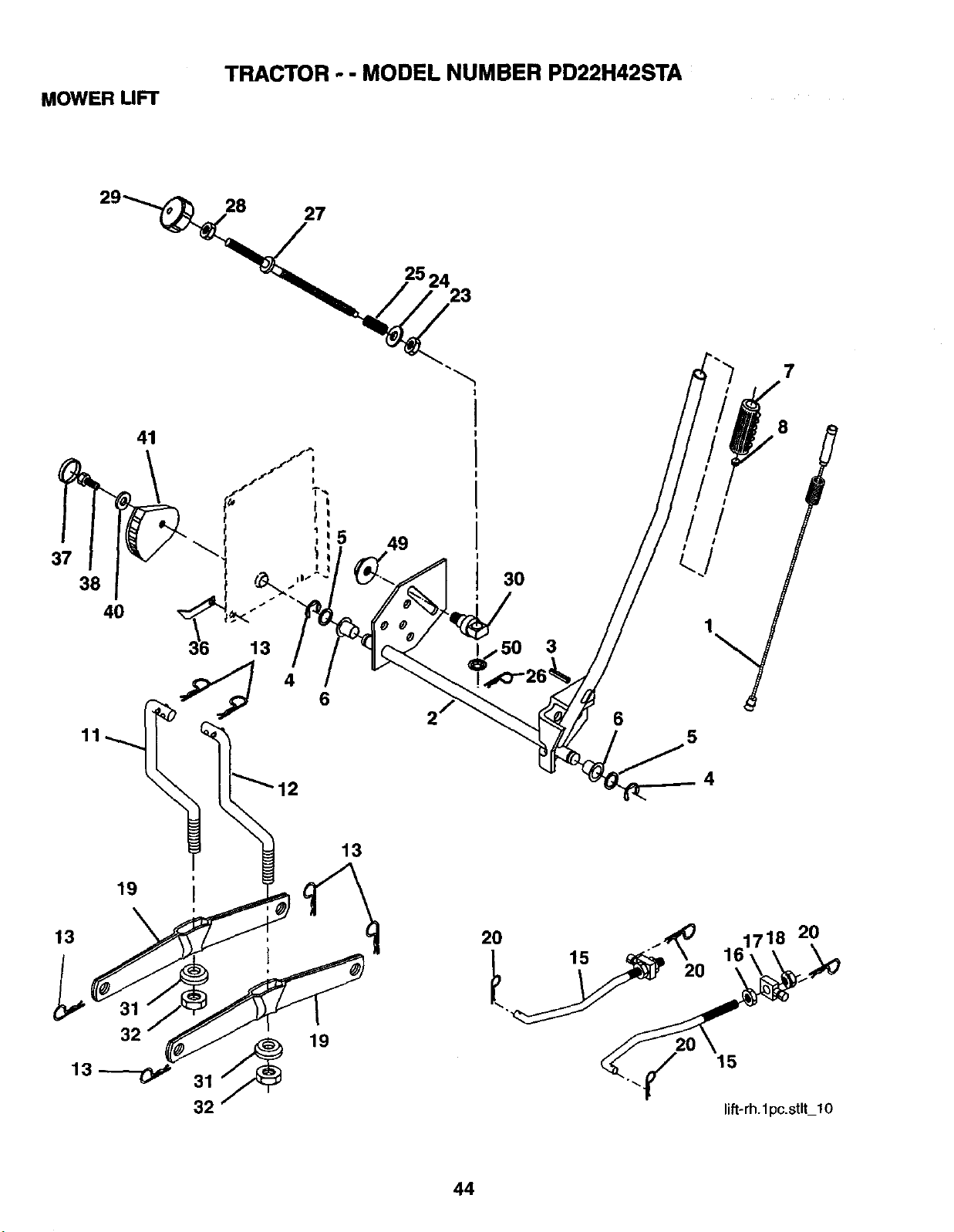
MOWER LIFT
TRACTOR - - MODEL NUMBER PD22H42STA
28
27
25 24
23
7
37
38
40
13
41
19
32
13---o,,
19
31
32
49
13
3O
6
5
4
.y 15
lift-rh.1pc.stlt_lO
44
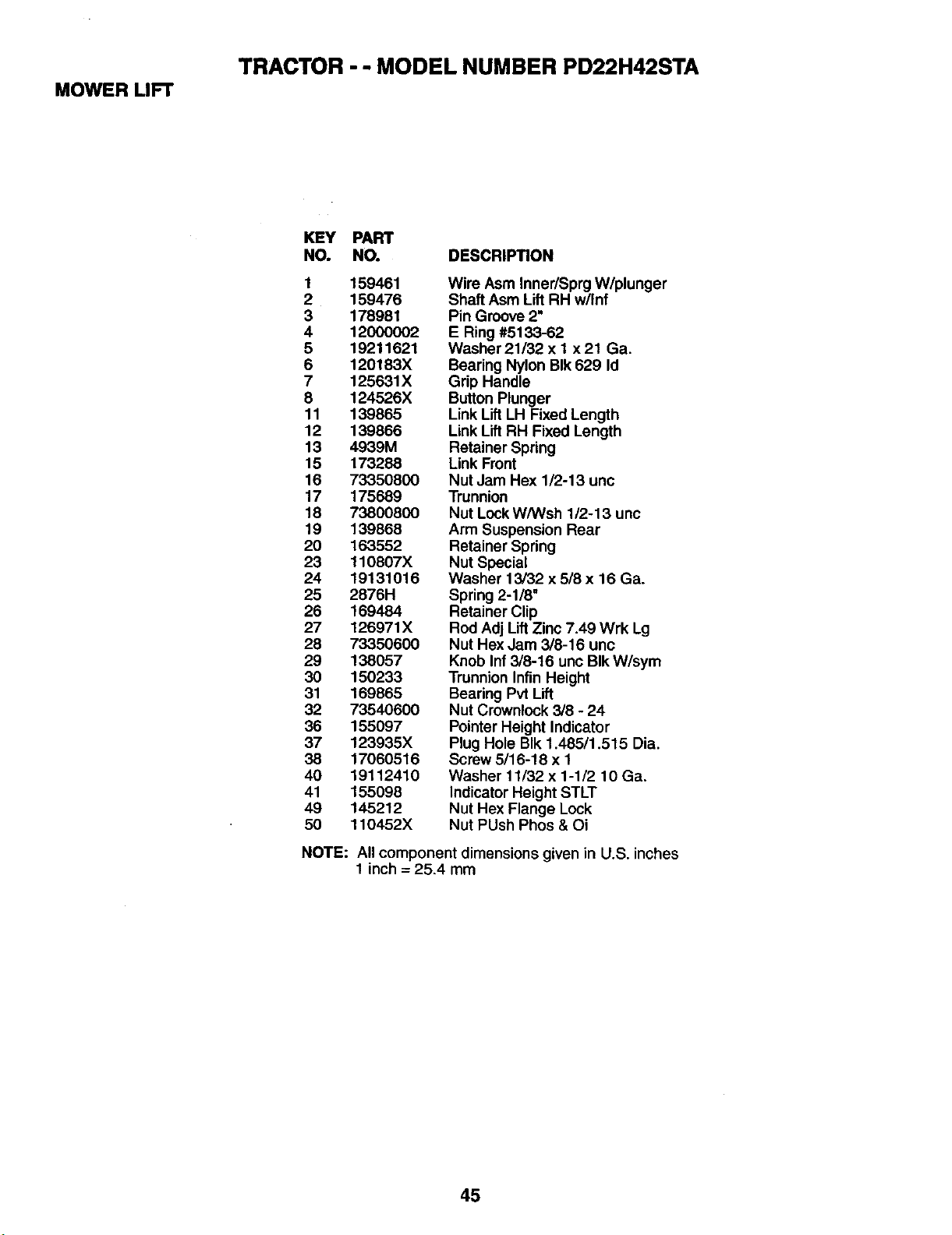
MOWER UFT
TRACTOR - - MODEL NUMBER PD22H42STA
KEY PART
NO. NO. DESCRIPTION
1 159461
2 159476
3 178981
4 12000002
5 19211621
6 120183X
7 125631X
8 124526X
11 139865
12 139866
13 4939M
15 173288
16 73350800
17 175689
18 73800800
19 139868
20 163552
23 110807X
24 19131016
25 2876H
26 169484
27 126971X
28 73350600
29 138057
30 150233
31 169865
32 73540600
36 155097
37 123935X
38 17060516
40 19112410
41 155098
49 145212
50 110452X
Wire Asm Inner/Sprg W/plunger
Shaft Asm Lift RH w/Inf
Pin Groove 2"
E Ring #5133-62
Washer 21/32 x 1 x21 Ga.
Bearing Nylon BIk 629 Id
Grip Handle
Button Plunger
LinkLift LH Fixed Length
LinkLift RH Fixed Length
Retainer Spring
Link Front
Nut Jam Hex 1/2-13 unc
Trunnion
Nut LockW/Wsh 1/2-13 unc
Arm Suspension Rear
Retainer Spring
Nut Special
Washer 13/32 x 5/8 x 16 Ga.
Spring 2-1/8"
Retainer Clip
Rod Adj Lift Zinc 7.49 Wrk Lg
Nut Hex Jam 3/8-16 unc
Knob Inf 3/8-16 unc BIk W/sym
Trunnion Infin Height
Bearing Pvt Lift
Nut Crownlock 3/8 - 24
Pointer Height Indicator
Plug Hole BIk 1.48511.515 Dia.
Screw 5/16-18 x 1
Washer 11/32 x 1-1/2 10 Ga.
Indicator Height STLT
Nut Hex Flange Lock
Nut PUsh Phos & Oi
NOTE: All component dimensions given in U.S. inches
1 inch = 25.4 mm
45
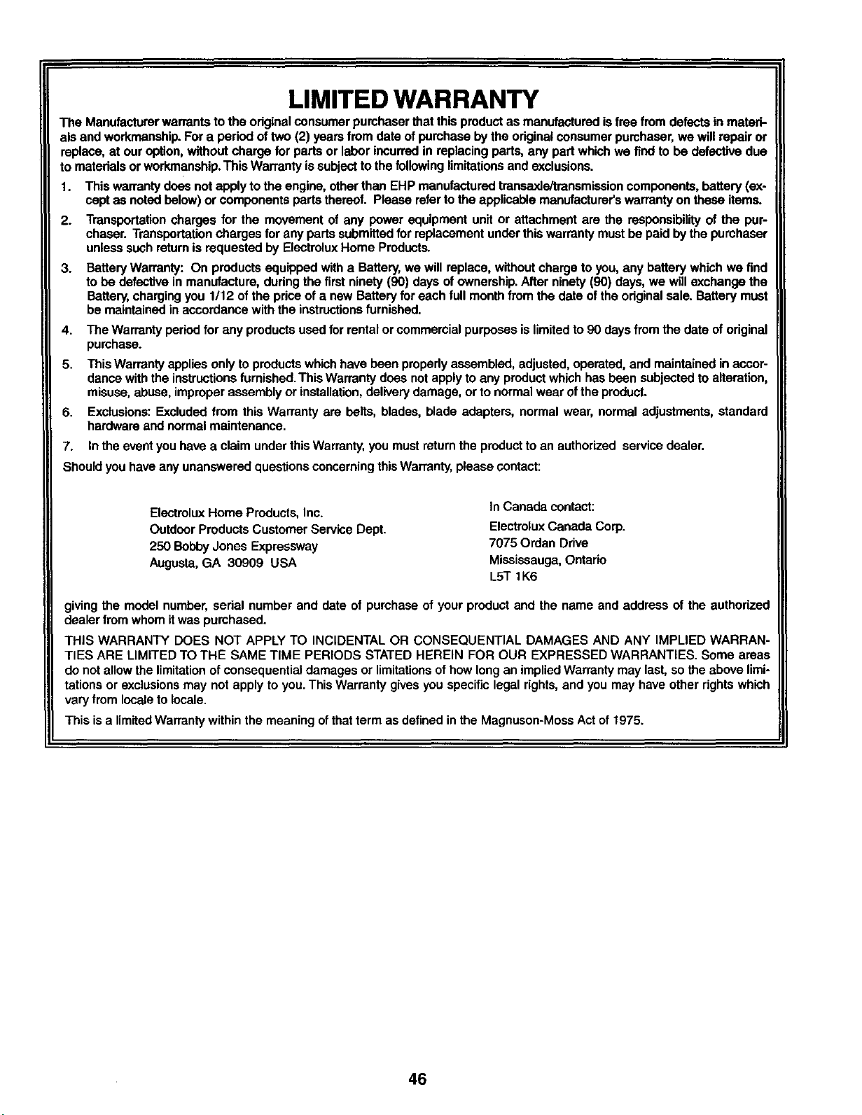
LIMITED WARRANTY
The Manufacturer warrants to the odginal consumer purchaser that this product as manufactured is free from defects in materi-
als and workmanship. For a period of two (2) years from date of purchase by the original consumer pumhaser, we wilerepair or
replace, at our option, without charge for parts or labor incurred in replacing pads, any part which we find to be defective due
to materials or workmanship. This Warranty issubject to the following limitations and exclusions.
1. This warranty does not apply to the engine, other than EHP manufactured transaxle/transmission components, battery (ex-
cept as noted below) or components parts thereof. Please refer to the applicable manufacturer's warranty on these items.
2. Transportation charges for the movement of any power equipment unit or attachment are the responsibility of the pur-
chaser. Transportation charges for any parts submitted for replacement under this warranty must be paid by the pumhaser
unless such return is requested by Electrolux Home Products.
3. Battery Warranty: On products equipped with a Battery, we will replace, without charge to you, any battery which we find
to be defective in manufacture, during the first ninety (90) days of ownership. After ninety (90) days, we will exchange the
Battery, charging you 1/12 of the price of a new Battery for each full month from the date of the original sale. Battery must
be maintained in accordance with the instructions furnished.
4. The Warrantyperiodfor any productsusedfor rentalor commercialpurposesislimitedto90 daysfromthedate oforiginal
purchase.
5. This Warranty applies only to products which have been properly assembled, adjusted, operated, and maintained in accor-
dance with the instructions furnished. This Warranty does not apply to any product which has been subjected to alteration,
misuse, abuse, improper assembly or installation, delivery damage, or to normal wear ofthe product.
6. Exclusions: Excluded from this Warranty are belts, blades, blade adapters, normal wear, normal adjustments, standard
hardware and normal maintenance.
7. In the event you have a claim under this Warranty, you must return the product to an authorized service dealer.
Should you have any unanswered questions concerning this Warranty, please contact:
Electrolux Home Products, Inc.
Outdoor Products Customer Service Dept.
250 Bobby Jones Expressway
Augusta, GA 30909 USA
In Canada contact:
Electrolux Canada Corp.
7075 Ordan Drive
Mississauga, Ontario
LST 1K6
giving the model number, serial number and date of purchase of your product and the name and address of the authorized
dealer from whom it was purchased.
THIS WARRANTY DOES NOT APPLY TO INCIDENTAL OR CONSEQUENTIAL DAMAGES AND ANY IMPLIED WARRAN-
TIES ARE LIMITED TO THE SAME TIME PERIODS STATED HEREIN FOR OUR EXPRESSED WARRANTIES. Some areas
do not allow the limitation of consequential damages or limitations of how long an implied Warranty may last, so the above limi-
tations or exclusions may not apply to you. This Warranty gives you specific legal rights, and you may have other rights which
vary from locale to locale.
This is a limited Warranty within the meaning ofthat term as defined in the Magnuson-Moss Act of 1975.
46
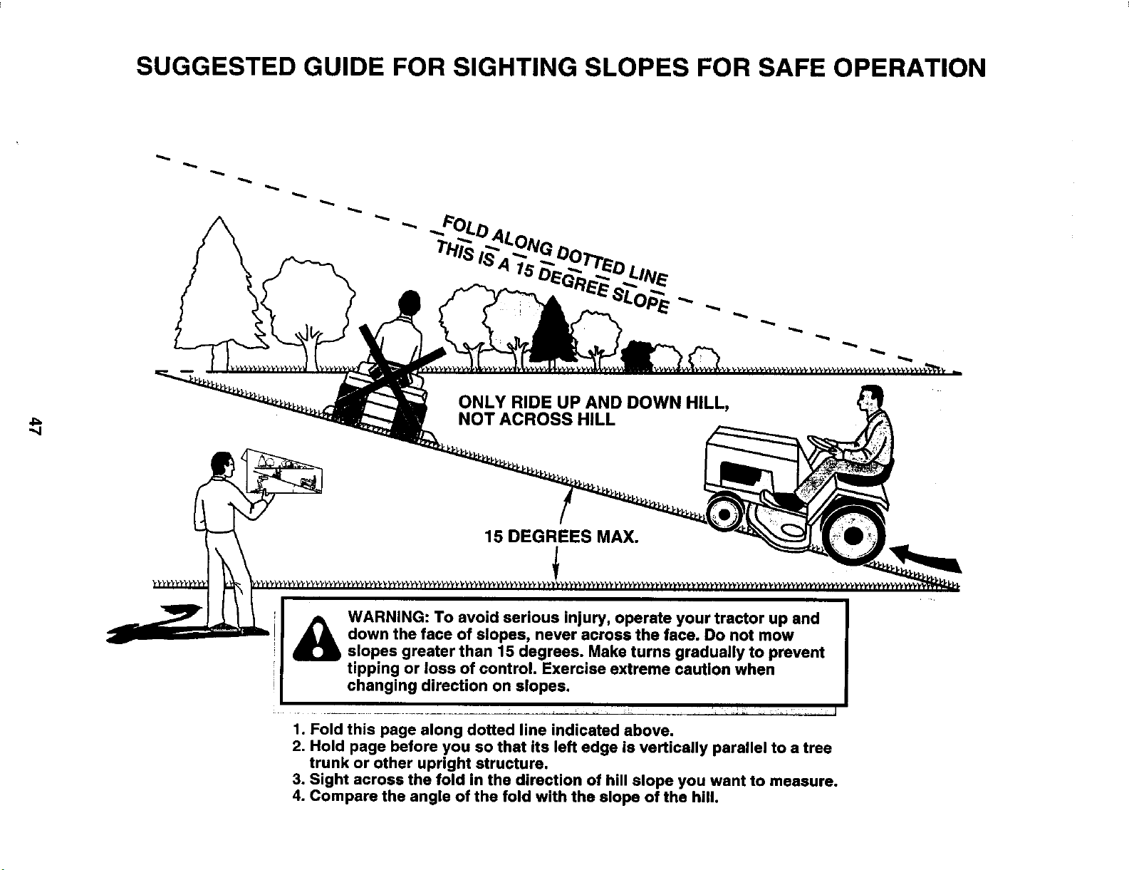
SUGGESTED GUIDE FOR SIGHTING SLOPES FOR SAFE OPERATION
4==
ONLY RIDE UP AND DOWN HILL,
NOT ACROSS HILL
15 DEGREES MAX.
A
WARNING: To avoid serious injury, operate your tractor up and
down the face of slopes, never across the face. Do not mow
slopes greater than 15 degrees. Make turns gradually to prevent
tipping or loss of control. Exercise extreme caution when
changing direction on slopes.
1. Fold this page along dotted line indicated above.
2, Hold page before you so that its left edge is vertically parallel to a tree
trunk or other upright structure.
3. Sight across the fold in the direction of hill slope you want to measure.
4. Compare the angle of the fold with the slope of the hill.
PARTS AND SERVICE
Your POLILAN PRO product has been expertly engineered and carefully manufactured to rigid quality standards. As with
all mechanical products, some adjustments or part replacement may be necessary during the life of your unit.
FOR SERVICE OR REPLACEMENT PARTS:
1. Consult your dealer/place of purchase.
2. Consult the yellow pages of your phone directory for the name of the nearest service dealer (under"saws" for Chain Saws
or under "lawn mowers" for Trimmers, Brushcutters, and Blowers).
3. For replacement parts, have available the following information:
a. Model Number/Manufacturer's I.D. Number.
b. Description of part.
NOTE:
Electrohix Home Products provides parts and service through its authorized distributors and dealers; there-
fore, all requests for parts and service should be directed to your local dealer(s). The philosophy of Electrolux
Home Products is to continually improve all of its products. If the operating characteristics or the appearance
of your product differs from those described in this Manual, please contact your local local dealer for updated
information and assistance.

