OWNER'S MANUAL
MODELNO.271491
14.5HP38INCH
LAWNTRACTOR
• Assembly
• Operation
Maintenance
• Service and Adjustments
• Troubleshooting
• Repair Parts
For Pads and Service, contact our authorized distributor.
call 1-800-849-1297 For Technical Assistance: call 1-800-829-5886
182989 2.13.02 RD
PRINTED IN U.S.A.
Safety Rules ......................................... 2
Product Specifications .......................... 5
AssemblylPre-Operation ...................... 7
Operation ............................................ 10
Maintenance Schedule ...................... 16
Maintenance ....................................... 16
Service and Adjustments.................... 20
Storage ............................................... 25
Troubleshooting ................................. 26
Repair Parts ........................................ 30
Warranty ............................................. 46
IMPORTANT: This cutting machine is capable of amputating hands and .feet and
throwing objects. Failure to observe the following sarety instructions could result an
serious injury or death.
I. GENERAL OPERATION
• Read, understand, and follow all
instructionsinthe manual and on the
machine before starting.
• Only allow responsibleadults, who are
familiar with the instructions,to operate
the machine.
• Clear the area of objectssuch as rocks,
toys, wire, etc., whichcould be picked up
and thrown by the blade.
• Be surethe area is clear of other people
before mowing. Stop machine if anyone
enters the area.
• Never carry passengers.
• Do not mow in reverse unless absolutely
necessary. Always look down and
behind before and while backing.
• Be aware of the mower discharge
directionand do not point itat anyone.
Do not operate the mower withouteither
the entire grass catcher or the guard in
place.
• Slow down before turning.
• Never leave a running machine unat-
tended. Always turn off blades, set
parking brake, stop engine, and remove
keys before dismounting.
• Turn off blades when not mowing.
• Stop engine before removing grass
catcher or uncloggingchute.
• Mow only in daylightor good artificial
light.
• Do not operate the machine while under
the influence of alcohol or drugs.
• Watch for traffic when operating near or
crossing roadways.
• Use extra care when loading or unload-
ing the machine Into a trailer or truck.
• Data indicatesthat operators, age 60
years and above, are involved in a large
percentage of dding mower-related
injuries. These operators should
evaluate their ability to operate the dding
mower safely enough to protect them-
selves and others from sedous injury.
• Keep machine free of grass, leaves or
other debds build-up which can touch
hot exhaust / engine parts and burn. Do
not allow the mower deck to plow leave_
or other debris which can cause build-
up to occur. Clean any oil orfuel
spillage before operating or storing the
machine. Allow machine to coolbefore
storage.
II, SLOPE OPERATION
Slopes are a majorfactor related toloss-of-
control and tipover accidents, which can
result in severe injuryor death. All slopes
require extra caution. Ifyou cannot back up
the slope or ifyou feel uneasy on it, do no1
mow it.
DO:
• Mow up and down slopes, notacross.
• Remove obstacles suchas rocks,tree
limbs,etc.
• Watch for holes, ruts,orbumps. Unever
terrain could overturnthe machine. Tall
grass can hide obstacles.
• Use slow speed. Choose a low gear so
thatyou will not have to stopor shift
while on the slope.
• Follow the manufacturer's recommenda-
tions for wheel weights or counter-
weights to improve stabilk'y.
• Use extra care with grass catchers or
other attachments. These can change
the stabilityofthe machine.
• Keep all movement on the slopes slow
and gradual. Do not make sudden
changes in speed or direction.
• Avoid startingor stoppingon a slope. If
tires losa traction, disengage the blade,€
and proceed slowly straightdown the
slope.
DO NOT:
• Do not turn on slopes unless neces-
sary, and then, turnslowly and gradually
downhill, if possible.
2
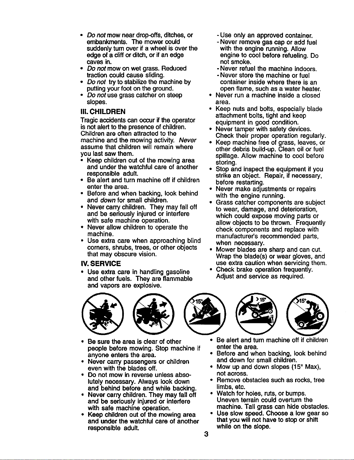
• Do not mow near drop-offs,ditches, or
embankments. The mower could
suddenly turn over if a wheel is over the
edge of a cliffor ditch, or ifan edge
caves in.
• Do not mow on wet grass. Reduced
traction could cause sliding.
• Do not try to stabilizethe machine by
puttingyour foot on the ground.
• Do not use grass catcher on steep
slopes.
IlL CHILDREN
Tragic accidents can occur if the operator
is not alert to the presence of children.
Children are often attracted to the
machine and the mowing activity. Never
assume that children will remain where
you last saw them.
• Keep children out of the mowing area
and under the watchful care of another
responsible adult.
• Be alert and turn machine off if children
enter the area.
• Before and when backing, look behind
and down for small children.
• Never carry children. They may fall off
and be seriously injured or interfere
with safe machine operation.
• Never allow children to operate the
machine.
• Use extra care when approaching blind
corners, shrubs, trees, or other objects
that may obscure vision.
IV. SERVICE
• Use extra care in handling gasoline
and other fuels. They are flammable
and vapors are explosive.
- Use only an approved container.
- Never remove gas cap or add fuel
with the engine running. Allow
engine to cool before refueling. Do
not smoke.
-Never refuel the machine indoors.
- Never store the machine or fuel
container inside where there is an
open flame, such as a water heater.
• Never run a machine inside a closed
area.
• Keep nuts and bolts, especially blade
attachment bolts, tight and keep
equipment in good condition.
• Never tamper with safety devices.
Check their proper operation regularly.
• Keep machine free of grass, leaves, or
other debris build-up. Clean oil or fuel
spillage. Allow machine to cool before
storing.
• Stop and inspect the equipment if you
strike an object. Repair, if necessary,
before restarting.
• Never make adjustments or repairs
with the engine running.
• Grass catcher components are subject
to wear, damage, and deterioration,
which could expose moving parts or
allow objectsto be thrown. Frequently
check components and replace with
manufacturer's recommended parts,
when necessary.
• Mower blades are sharp and can cut.
Wrap the blade(s) or wear gloves, and
use extra caution when servicing them.
• Check brake operation frequently.
Adjust and service as required.
• Be sure the area is clear of other • Be alert and turn machine off if children
people before mowing. Stop machine if
anyone enters the area.
• Never carry passengers or children
even with the blades off.
• Do not mow in reverse unless abso-
lutely necessary. Always look down
and behind before and while backing.
• Never carry children. They may fall off
and be seriously injured or interfere
with safe machine operation.
• Keep children out of the mowing area
and under the watchful care of another
responsible adult.
3
enter the area.
• Before and when backing, look behind
and down for small children.
• Mow up and down slopes (15o Max),
not across.
• Remove obstacles such as rocks,tree
limbs, etc.
• Watch for holes, ruts,or bumps.
Uneven terrain could overturn the
machine. Tall grass can hide obstacles.
• Use slow speed. Choose a low gear so
that you will not have to stop or shift
while on the slope.
• Avoidstartingorstoppingonaslope.If
tireslosetraction,disengagethe
bladesandproceedslowlystraight
downthe slope.
• If machine stops while going uphill,
disengage blades, shift into reverse
and back down slowly.
• Do not turn on slopes unless neces-
sary, and then, turn slowly and gradu-
ally downhill, if possible.
_Look for this symbol to point out
important safety precautions. It means
CAUTION!!I BECOMEALERTll! YOUR
SAFETY IS INVOLVED.
CAUTION: In order to prevent
accidental starting when setting up,
transporting, adjusting or making repairs,
always disconnect spark plug wire and
place wire where it cannot contact spark
plug.
CAUTION: Do not coast down a hill
in neutral, you may lose control of the
tractor.
CAUTION: Tow only the attachments
that are recommended by and comply
with specifications of the manufacturer of
your tractor. Use common sense when
towing. Operate only at the lowest
possible speed when on a slope. Too
heavy of a load, while on a slope, is
dangerous. "13rescan lose tractionwith
the ground and cause you to lose control
of your tractor.
&WARNING: Engine exhaust, some of
its constituents, and certain vehicle
components contain or emit chemicals
known to the State of Califomia to cause
cancer and birth defects or other repro-
ductive harm.
WARNING: Battery posts,terminals
and related accessories contain lead and
lead compounds, chemicals known to the
State of California to cause cancer and
birth defects or other reproductive harm.
Wash hands after handling.
4
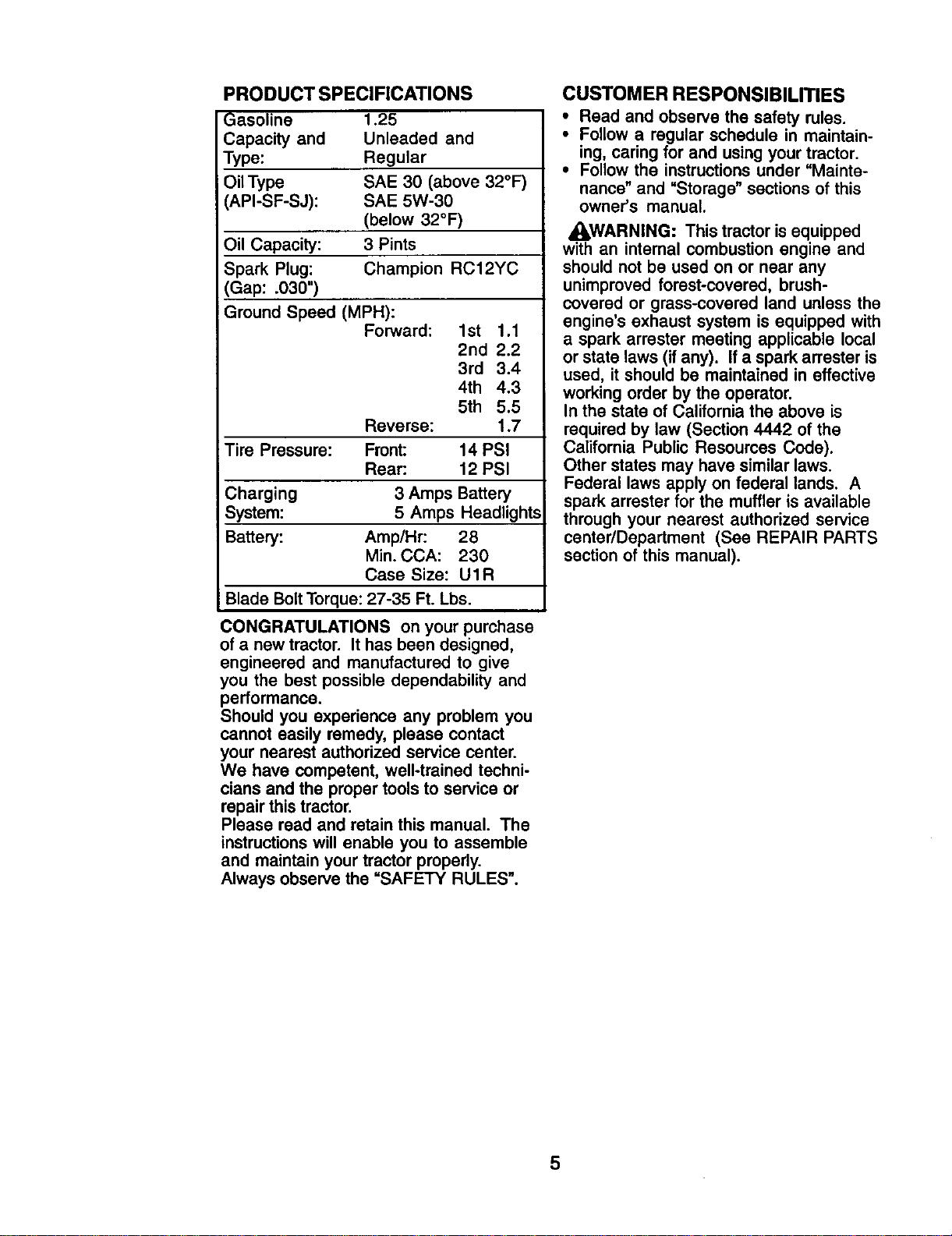
PRODUCT SPECIFICATIONS
Gasoline 1.25
Capacity and Unleaded and
Type: Regular
Oil Type SAE 30 (above 32°F)
API-SF-SJ): SAE 5W-30
(below 32°F)
Oil Capacity: 3 Pints
Spark Plug: Champion RC12YC
(Gap: .030")
Ground Speed (MPH):
Forward: 1st 1.1
2nd 2.2
3rd 3.4
4th 4.3
5th 5.5
Reverse: 1.7
Tire Pressure: Front: 14 PSI
Rear: 12 PSI
Charging 3 Amps Battery
System: 5 Amps Headlights
Battery: Amp/Hr: 28
Min. CCA: 230
Case Size: UIR
Blade Bolt Torque: 27-35 Ft. Lbs.
CONGRATULATIONS on your purchase
of a new tractor. It has been designed,
engineered and manufactured to give
you the best possible dependability and
performance.
Should you experience any problem you
cannot easily remedy, please contact
your nearest authorized service center.
We have competent, well-trained techni-
cians and the proper tools to service or
repair this tractor.
Please read and retain this manual. The
instructionswill enable you to assemble
and maintain your tractor properly.
Always observe the =SAFETY RULES".
CUSTOMER RESPONSIBILITIES
• Read and observe the safety rules.
• Follow a regular schedule in maintain-
ing, caring for and using your tractor.
• Follow the instructions under =Mainte-
nance _ and =Storage" sections of this
owner's manual.
,_I,WARNING: This tractor isequipped
with an internal combustion engine and
should not be used on or near any
unimproved forest-covered, brush-
covered or grass-covered land unless the
engine's exhaust system is equipped with
a spark arrester meeting applicable local
or state laws (if any). Ifa spark arrester is
used, it should be maintained in effective
working order by the operator.
In the state of California the above is
required by law (Section 4442 of the
California Public Resources Code).
Other states may have similar laws.
Federal laws apply on federal lands. A
spark arrester for the muffler is available
through your nearest authorized service
center/Deparfment (See REPAIR PARTS
section of this manual).
5
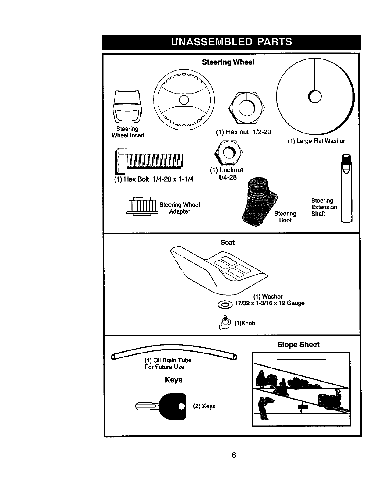
Steering Wheel
Steedng
Wheel Insert
(1) Hex Bolt 1/4-28 x 1-1/4
_L Steedng Wheel
Adapter
(1) Hex nut 1/2-20
(1) Locknut
1/4-28 _P_teedngBoot
(1) Large Flat Washer
Steering
Extension
Shaft
Seat
(1) Washer
17/32 x 1-3/16 x 12 Gauge
_ (1)Knob
(__(1) Oil Drain Tub_
For Future Use
Keys
<__ (2) Keys
Slope Sheet
6
Your new tractor has been assembled at the factory with the exception of those parts
left unassembled for shipping purposes. To ensure safe and proper operation of your
tractor all parts and hardware you assemble must be tightened securely, Use the
correct tools as necessary to insure proper tightness. Review the video cassette before
you begin.
TOOLS REQUIRED FOR
ASSEMBLY
A socket wrench set will make assembly
easier. Standard wrench sizes you need
are listed below.
(1) 3/4"wrench (1) Pliers
(2) 7/16" wrench (1) Utility knife
(1) Tire pressure gauge
When right or left hand is mentioned in
this manual, it means, from your point of
view, when you are in the operating
position (seated behind the steering
wheel).
TO REMOVE TRACTOR FROM
CARTON
UNPACK CARTON
1. Remove all accessible loose parts
and parts boxes from carton.
2. Cut, from top to bottom, along lines
on all four corners of carton, and lay
panels flat.
3. Check for any additional loose parts
or cartons and remove.
BEFORE REMOVING TRACTOR
FROM SKID
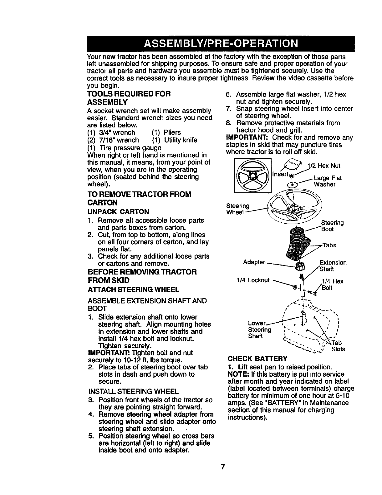
ATrACH STEERING WHEEL
ASSEMBLE EXTENSION SHAFT AND
BOOT
1. Slide extension shaft onto lower
steering shaft. Align mounting holes
in extension and lower shafts and
install 1/4 hex bolt and Iocknut.
Tighten securely.
IMPORTANT: Tighten bolt and nut
securely to 10-12 ft. Ibs torque.
2. Place tabs of steering boot over tab
slots in dash and push down to
secure.
INSTALL STEERING WHEEL
3, Positionfront wheels of the tractor so
they are pointing straight forward.
4. Remove steedng wheel adapter from
steedng wheel and slide adapter onto
steering shaft extension,
5. Position steering wheel so cross bars
are horizontal (left to dght) and slide
inside boot and onto adapter.
6. Assemble large flat washer, 1/2 hex
nut and tighten securely.
7. Snap steering wheel insert into center
of steering wheel.
8. Remove protective materials from
tractor hood and grill.
IMPORTANT: Check for and remove any
staples in skid that may puncture tires
where tractor is to roll off skid.
CHECK BATTERY
1. Lift seat pan to raised position.
NOTE: If this battery is put into service
after month and year indicated on label
(label located between terminals) charge
battery for minimum of one hour at 6-10
amps. (See "BATTERY" in Maintenance
section of this manual for charging
instructions).
7
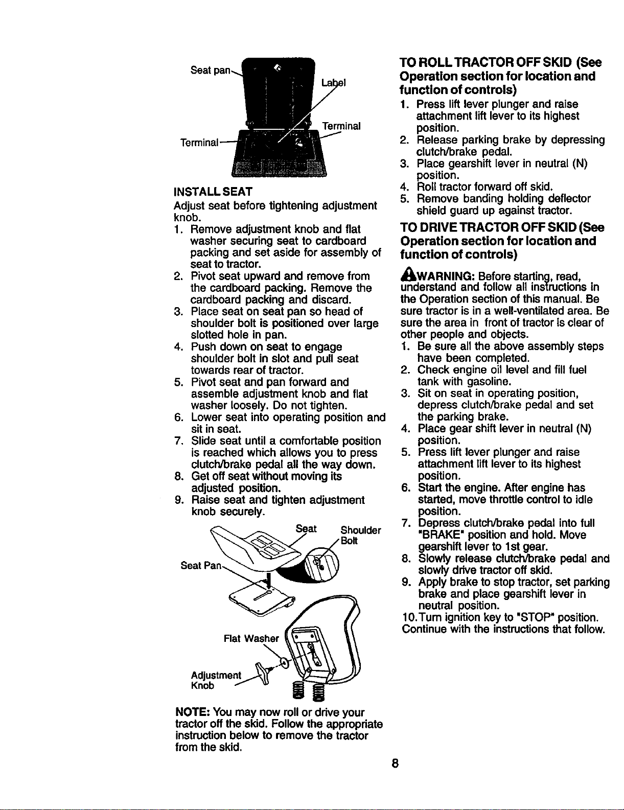
Seat
Terminal
INSTALL SEAT
Adjust seat before tightening adjustment
knob.
1. Remove adjustment knob and fiat
washer securing seat to cardboard
packing and set aside for assembly of
seat to tractor.
2. Pivot seat upward and remove from
the cardboard packing. Remove the
cardboard packing and discard.
3. Place seat on seat pan so head of
shoulder bolt is positioned over large
slotted hole in pan.
4. Push down on seat to engage
shoulder bolt in slot and pull seat
towards rear of tractor.
5. Pivot seat and pan forward and
assemble adjustment knob and flat
washer loosely. Do not tighten.
6. Lower seat into operating position and
sit in seat.
7. Slide seat until a comfortable position
is reached which allows you to press
clutch/brake pedal all the way down.
8. Get off seat without moving its
adjusted position.
9. Raise seat and tighten adjustment
knob securely.
Seat Shoulder
Seat Pan-.
Flat Washer
TO ROLLTRACTOR OFF SKID (See
Operation section for location and
function of controls)
1. Press lift lever plunger and raise
attachment liftlever to its highest
position.
2. Release parking brake by depressing
clutch/brake pedal.
3. Place gearshift lever in neutral (N)
position.
4, Roll tractor forward off skid.
5. Remove banding holding deflector
shield guard up against tractor,
TO DRIVE TRACTOR OFF SKID (See
Operation section for location and
function of controls)
_WARNING: Before starting, read,
understand and follow all instructions in
the Operation section of this manual. Be
sure tractor is in a well-ventilated area. Be
sure the area in front of tractor is clear of
other people and objects.
1. Be sure all the above assembly steps
have been completed.
2. Check engine oil level and fill fuel
tank with gasoline.
3. Sit on seat in operating position,
depress clutch/brake pedal and set
the parking brake.
4. Place gear shift lever in neutral (N)
position.
5. Press lift lever plunger and raise
attachment lift lever to its highest
position.
6. Start the engine, After engine has
started, move throttle control to idle
position.
7. Depress clutch/brake pedal into full
'BRAKE" position and hold. Move
gearshift lever to 1st gear.
8. Slowly release clutch/brake pedal and
slowly drive tractor off skid.
9. Apply brake to stop tractor, set parking
brake and place gearshift lever in
neutral position.
10.Tum ignition key to "STOP" position.
Continue with the instructions that follow.
Adjustment
Knob
NOTE: You may now rollor drive your
tractor off the skid. Follow the appropriate
instructionbelow to remove the tractor
from the skid.
8
CHECK TIRE PRESSURE
The tiros on your tractor were overin-
flated at the factory for shipping pur-
poses. Correct tire pressure is important
for best cutting performance.
* Reduce tire pressure to PSI shown in
=PRODUCT SPECIFICATIONS"
section of this manual.
CHECK FOR PROPER POSITION
OF ALL BELTS
See the figures that are shown for
replacing motion and mower blade drive
belts in the Service and Adjustments
section of this manual. Verify that the
belts are routed correctly.
CHECK DECKLEVELNESS
For best cutting results, mower housing
should be properly leveled. See "TO
LEVEL MOWER HOUSING" in the
Service and Adjustments section of this
manual.
CHECK BRAKE SYSTEM
After you learn how to operate your
tractor, check to see that the brake is
properly adjusted. See "TO ADJUST
BRAKE" in the Service and Adjustments
section of this manual.
/CHECKLIST
Before you operate your new tractor,we
wish to assure that you receive the best
performance and satisfactionfrom this
Quality Product.
Please review the following checklist:
,/All assembly instructionshave been
completed.
•/ No remaining loose parts in carton.
,/Battery is properly prepared and
charged. (Minimum 1 hour at 6 amps).
•/Seat is adjusted comfortably and
tightened securely.
,/All tires are properly inflated. (For
shipping purposes, the tires were
overinflated at the factory).
4"Be sure mower deck is properly leveled
side-to-side/front-to-rear for best cutting
results. (Tires must be properly inflated
for leveling).
,/Check mower and drive belts. Be sure
they are routed properly around pulleys
and inside all belt keepers.
,/Check wiring. See that all connections
are still secure and wires are properly
clamped.
While learning how to use your tractor,
pay extra attention to the following
important items:
,/Engine oil is at proper level.
,/Fuel tank is filled with fresh, clean,
regular unleaded gasoline.
/ Become familiar with all controls, their
location and function. Operate them
before you start the engine.
,/Be sure brake system is in safe
operating condition.
9

These symbols may appear on your tractor or in literature supplied with the product.
Learn and understand their meaning.
BA'(-rERY CAUTION OR REVERSE FORWARD FAST SLOW
WARNING
j
oi k
ENG,.EONENG,NEOFFO,'PRESSUREUGHTSO.OV_,_T_.P
FUEL CHOKE MOWER HEIGHT PARKING BRAKE UNLOCKED MOWER LIFT
LOCKED
R N H L
A'rrACHMENT REVERSE NEUTRAL HIGH LOW PARKING BRAKE
CLUTCH ENGAGED
ATTACHMENT KEEP AREA CLEAR SLOPE HAZARDS
IGNmON CLUTCH DISENGAGED (SEE SAFETY RULES SECTION)
DANGER, KEEP HANDS AND FEET AWAY
10
FREE WHEEL
(Automatic Models only)
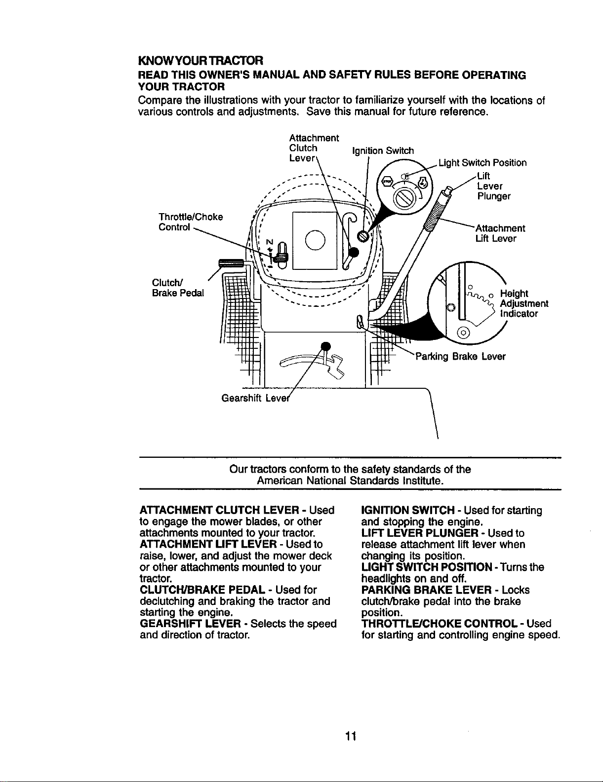
KNOWYOUR TRACTOR
READ THIS OWNER'S MANUAL AND SAFETY RULES BEFORE OPERATING
YOUR TRACTOR
Compare the illustrations with your tractor to familiarize yourself with the locations of
various controls and adjustments, Save this manual for future reference.
Throttle/Choke
Attachment
Clutch IgnitionSwitch
Lever
..... Lever
Plunger
Attachment
Lift Lever
Clutch/
Brake Pedal
Height
Adjustment
Indicator
Brake Lever
Gearshift
Our tractors conform to the safetystandards of the
American National Standards Institute.
ATTACHMENT CLUTCH LEVER - Used
to engage the mower blades, or other
attachments mounted to your tractor.
ATTACHMENT LIFT LEVER - Used to
raise, lower, and adjust the mower deck
or other attachments mounted to your
tractor.
CLUTCH/BRAKE PEDAL - Used for
declutching and braking the tractor and
starting the engine.
GEARSHIFT LEVER - Selects the speed
and direction of tractor.
IGNITION SWITCH - Used for starting
and stopping the engine.
LIFT LEVER PLUNGER - Used to
release attachment lift lever when
changing its position.
LIGHT SWITCH POSITION - Turns the
headlights on and off.
PARKING BRAKE LEVER - Locks
clutch/brake pedal into the brake
position.
THRO'I'rLE/CHOKE CONTROL - Used
for starting and controlling engine speed.
11
The operation of any tractor can result in foreign objects thrown into the
eyes, which can result in severe eye damage. Always wear safety
glasses or eye shields while operating your tractor or performing any
adjustments or repairs. We recommend a wide vision safety mask over
spectacles or standard safety glasses.
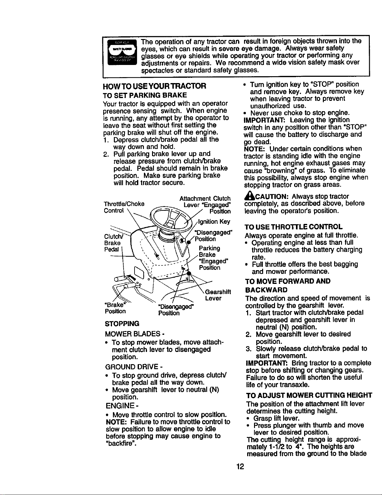
HOW TO USE YOUR TRACTOR
TO SET PARKING BRAKE
Your tractor is equipped with an operator
presence sensing switch. When engine
is running,any attempt by the operator to
leave the seat without first setting the
parking brake will shut off the engine.
1. Depress clutch/brake pedal all the
way down and hold.
2. Pull parking brake lever up and
release pressure from clutch/brake
pedal. Pedal should remain in brake
position. Make sure parking brake
will hold tractor secure.
Attachment Clutch
Throttle/Choke Lever =Engaged"
Control\ _x__\__ _ Position
\ "_/j::_-[ _/Ignition Key
__ ,_/=Disengagsd"
osit,on
Pedalt \ " \\:. \ _/A Parking
', _,, _ _/_ /Brake
._... v _ .,/,,/ =Engaged"
V _ \ Gearshift
/ Lever
=Brake' =Disengaged"
PosiUon Position
STOPPING
MOWER BLADES -
• To stop mower blades, move attach-
ment clutch lever to disengaged
position.
GROUND DRIVE -
• To stop ground drive, depress clutch/
brake pedal all the way down.
• Move gearshift lever to neutral (N)
position.
ENGINE -
• Move throttle controlto slow position.
NOTE: Failure to move throttle control to
slow position to allow engine to idle
before stopping may cause engine to
"backfire".
• Turn ignition key to =STOP" position
and remove key. Always remove key
when leaving tractor to prevent
unauthorized use.
• Never use choke to stop engine.
IMPORTANT: Leaving the ignition
switch in any positionother than "STOP"
will cause the battery to discharge and
go dead.
NOTE: Under certain conditionswhen
tractor is standing idle with the engine
running, hot engine exhaust gases may
cause =browning" of grass. To eliminate
this possibility,always stop engine when
stoppingtractor on grass areas.
_CAUTION: Always stop tractor
completely, as descdbed above, before
leaving the operator's position.
TO USE THROTTLE CONTROL
Always operate engine at full throttle.
• Operating engine at less than full
throttle reduces the battery charging
rate.
• Full throttle offers the best bagging
and mower performance.
TO MOVE FORWARD AND
BACKWARD
The direction and speed of movement is
controlled by the gearshift lever.
1. Start tractor with clutch/brake pedal
depressed and gearshift lever in
neutral (N) position.
2. Move gearshift lever to desired
position.
3. Slowly release clutch/brake pedal to
start movement.
IMPORTANT: Bdng tractor to a complete
stop before shiftingor changing gears.
Failure to do so will shorten the useful
life of your transaxle.
TO ADJUST MOWER CuI-rlNG HEIGHT
The position of the attachment lift lever
determines the cutting height.
• Grasp lift lever.
• Press plunger with thumb and move
lever to desired position,
The cutting height range is approxi-
mately 1-1/2 to 4". The heights are
measured from the ground to the blade
12
tip with the engine not running. These
heights are approximate and may vary
depending upon soil conditions, height of
grass and types of grass being mowed.
• The average lawn should be cut to
approximately 2-1/2 inches during the
cool season and to over 3 inches
during hot months. For healthier and
better looking lawns, mow often and
after moderate growth.
• For best cutting performance, grass
over 6 inches in height should be
mowed twice. Make the first cut
relatively high; the second to desired
height.
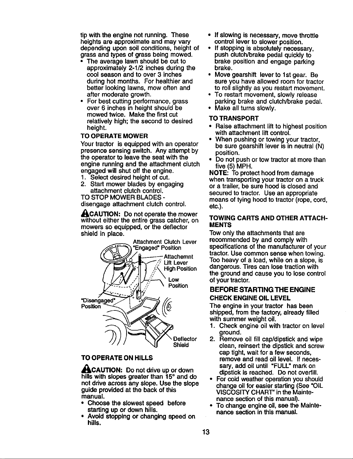
TO OPERATE MOWER
Your tractor is equipped with an operator
presence sensing switch. Any attempt by
the operator to leave the seat with the
engine running and the attachment clutch
engaged will shut off the engine.
1. Select desired height of cut.
2. Start mower blades by engaging
attachment clutch control.
TO STOP MOWER BLADES -
disengage attachment clutch control.
_CAUTION: Do not operate the mower
without either the entire grass catcher, on
mowers so equipped, or the deflector
shield in place.
__ Attachment Clutch Lever
_"_3 =Engaged" Position
_._ _-f/_X / ----------Attachemnt
_. _--_;R_.-'='_L=_- _.._,,'_' Lift Lever
"Disengaged'.. " I _,'_-_[/_
Position_ ,,,_
TO OPERATE ON HILLS
A
4_,CAUTION" Do not drive up or down
hills with slopes greater than 15 ° and do
not drive across any slope. Use the slope
guide provided at the back of this
manual.
• Choose the slowest speed before
starting up or down hills.
• Avoid stopping or changing speed on
hills.
• If slowing is necessary, move throttle
control lever to slower position.
• If stopping is absolutely necessary,
push clutch/brake pedal quickly to
brake position and engage parking
brake.
• Move gearshift lever to 1st gear. Be
sure you have allowed room for tractor
to roll slightly as you restart movement.
• To restart movement, slowly release
parking brake and clutch/brake pedal.
• Make all turns slowly.
TO TRANSPORT
• Raise attachment lift to highest position
with attachment lift control.
• When pushing or towing your tractor,
be sure gearshift lever is in neutral (N)
position.
• Do not push or tow tractor at more than
five (5) MPH.
NOTE: To protect hood from damage
when transporting your tractor on a truck
or a trailer, be sure hood is closed and
secured to tractor. Use an appropriate
means of tying hood to tractor (rope, cord,
etc.).
TOWING CARTS AND OTHER ATTACH-
MENTS
Tow only the attachments that are
recommended by and comply with
specifications of the manufacturer of your
tractor. Use common sense when towing.
Too heavy of a load, while on a slope, is
dangerous. Tires can lose traction with
the ground and cause you to lose control
of your tractor.
BEFORE STARTING THE ENGINE
CHECK ENGINE OIL LEVEL
The engine in your tractor has been
shipped, from the factory, already filled
with summer weight oil.
1. Check engine oil with tractor on level
ground.
2. Remove oil fill cap/dipstick and wipe
clean, reinsert the dipstick and screw
cap tight, wait for a few seconds,
remove and read oil level. If neces-
sary, add oil until "FULL" mark on
dipstick is reached. Do not overfill.
• For cold weather operation you should
change oil for easier starting (See "OiL
VISCOSITY CHART" in the Mainte-
nance section of this manual).
• To change engine oil, see the Mainte-
nance section in this manual.
13
ADD GASOLINE
• Fill fuel tank to bottom of filler neck. Do
not overfill. Use fresh, clean, regular
unleaded gasoline with a minimum of
87 octane. (Use of leaded gasoline
will increase carbon and lead oxide
deposits and reduce valve life). Do not
mix oil with gasoline. Purchase fuel in
quantities that can be used within 30
days to assure fuel freshness.
_,CAUTION: Wipe off any spilled oil or
fuel. Do not store, spill or use gasoline
near an open flame.
IMPORTANT: When operating in
temperatures below32°F(0°C), use fresh,
clean winter grade gasoline to help
insure good cold weather starting.
_CAUTION: Alcohol blended fuels
(called gasohol or using ethanol or
methanol) can attract moisture which
leads to separation and formation of
acids during storage. Acidic gas can
damage the fuel system of an engine
while in storage. To avoid engine
problems, the fuel system should be
emptied before storage of 30 claysor
longer. Drain the gas tank, start the
engine and let it run until the fuel lines
and carburetor are empty. Use fresh fuel
next season. See Storage Instructionsfor
additional information. Never use engine
or carburetor cleaner products in the fuel
tank or permanent damage may occur.
TO START ENGINE
Whenstarlingtheenginefor the firsttimeorif
the enginehasrunoutof fuel,itwilltakeextra
crankingtime tomove fuelfromthe tankto
the engine.
1. Sit on seat in operating position,
depress clutch/brake pedal and set
parking brake.
2. Place gear shift lever in neutral (N)
position.
3. Move attachment clutch to disen-
gaged position.
4. Move throttle controlto choke position.
NOTE: Beforestarting,readthe warmand
coldstarlingproceduresbelow.
5. Insert key into ignitionand turn key
clockwise to start position and release
key as soon as engine starts. Do not
run starter continuouslyfor more than
fifteen seconds per minute. Ifthe
engine does not start after several
attempts, movethrottlecontrol to fast
position,wait a few minutes and try
again. If engine stilldoes not start,
move the throttlecontrol back to the
choke position and retry.
WARMWEATHER STARTING(50° Fand
above)
6. When engine starts, move the throttle
control to the fast position.
• The attachments and ground drive can
now be used. If the engine does not
accept the load, restart the engine and
allow it to warm up for one minute
using the choke as described above.
COLD WEATHER STARTING( 50° F and
below)
6. When engine starts, leave throttle
control in choke position until engine
warms up and begins to run roughly.
Once rough running begins, immedi-
ately move the throttlecontrol to the
fast position. Engine warm-up may
take from several seconds to several
minutes (the colder the temperature,
the longer the warm-up).
• The attachments can also be used
during the engine warm-up period.
NOTE: Ifat a highaltitude(above3000 feet)
or incoldtemperatures (below32 F) the
carburetorfuel mixturemayneedto be
adjustedforbestengineperformance(see
_1"OADJUST CARBURETOR" inthe Service
and Adjustmentssectionofthis manual).
14
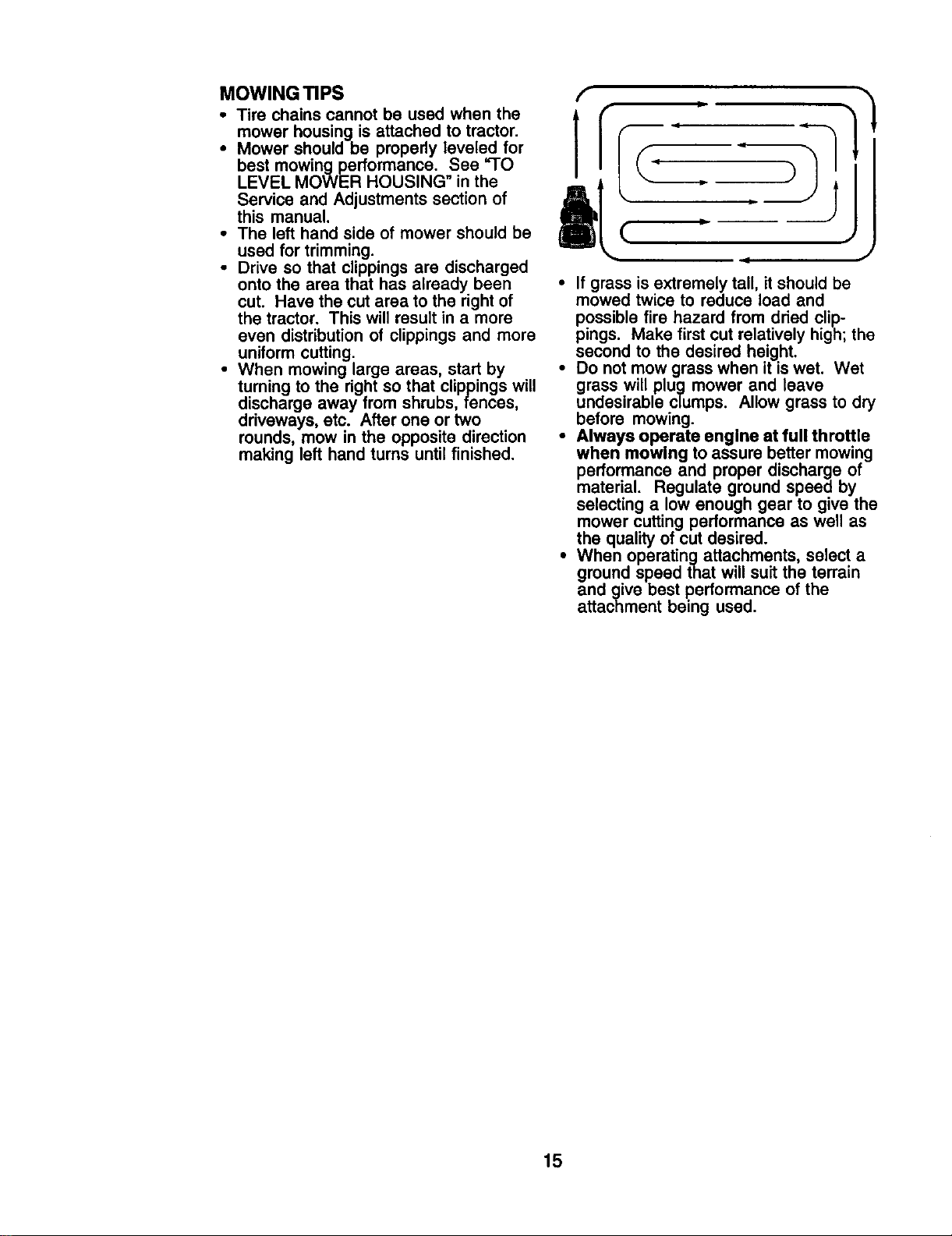
MOWING TIPS
• Tire chains cannot be used when the
mower housing is attached to tractor.
• Mower should be properly leveled for
best mowing performance. See "TO
LEVEL MOWER HOUSING" in the
Service and Adjustments section of
this manual.
• The left hand side of mower should be
used for trimming.
• Drive so that clippings are discharged
onto the area that has already been
cut. Have the cut area to the right of
the tractor. This will result in a more
even distribution of clippings and more
uniform cutting.
• When mowing large areas, start by
turning to the right so that clippings will
discharge away from shrubs, fences,
driveways, etc. After one or two
rounds, mow in the opposite direction
making left hand turns until finished.
• If grass is extremely tall, it should be
mowed twice to reduce toad and
possible fire hazard from dried clip-
pings. Make first cut relatively high; the
second to the desired height.
• Do not mow grass when it iswet. Wet
grass will plug mower and leave
undesirable clumps. Allow grass to dry
before mowing.
• Always operate engine at full throttle
when mowing to assure better mowing
performance and proper discharge of
material. Regulate ground speed by
selecting a low enough gear to give the
mower cutting performance as well as
the quality of cut desired.
• When operatingattachments, select a
ground speed that will suit the terrain
and give best performance of the
attachment being used.
15
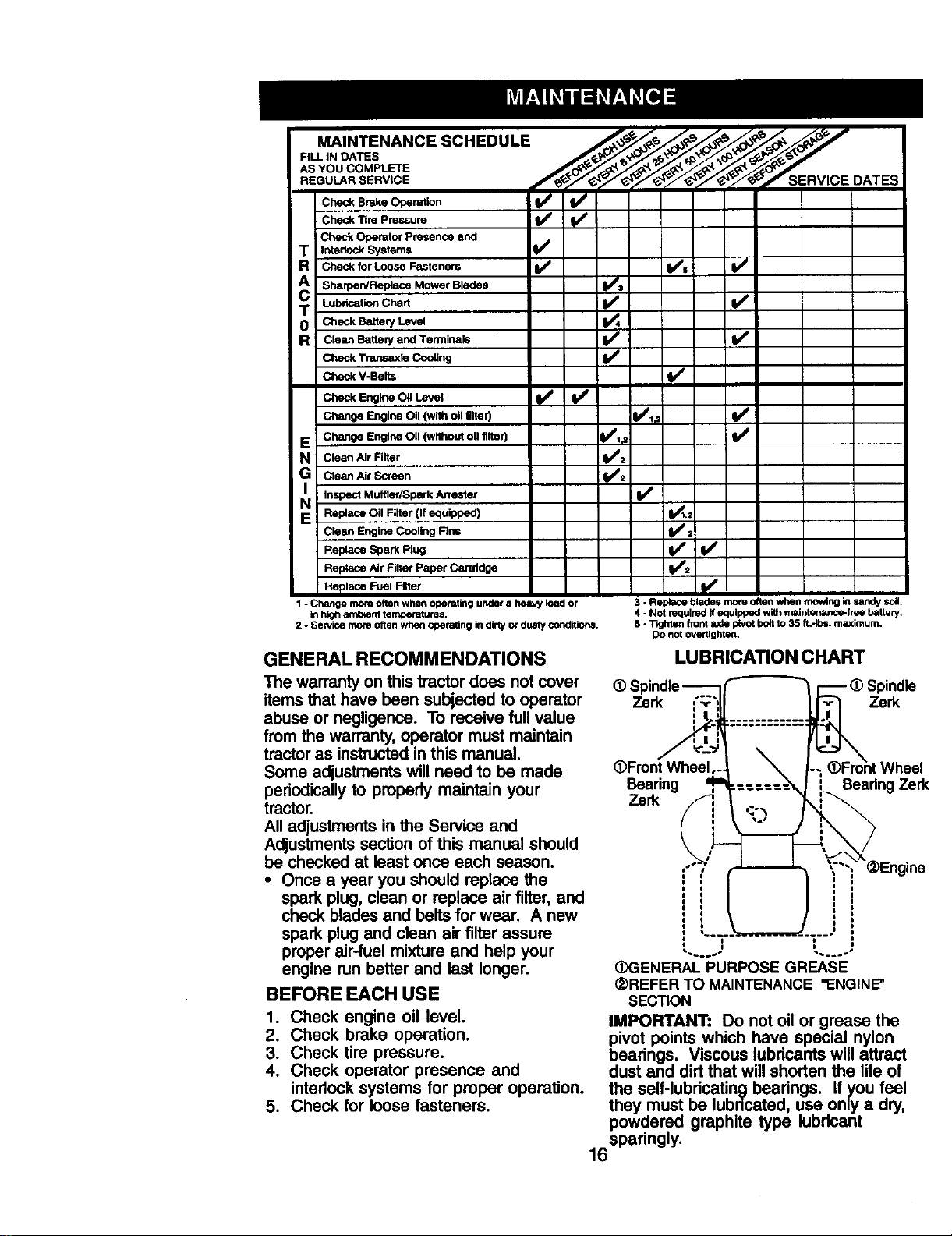
MAINTENANCE SCHEDULE ,,,_,,_-_ _ _,_ _
O..O.=..n
Check Tire Pressure 1
Check Operator Presence and
T Interlock Systems
R Check for Loose Fasteners V / V's I_/
A Sharpen/Replace Mower Blades I_s
i
T Lubr_=k_Cha, JIv" I/i
0 Check Battery Level
R Clean Battery and Termina_ _V' I_
CheckTransaxie Cooling
Check V-Belts
E Change Engine Oil (without oll ltlter) l_,_. li/
N Clea. Air Filter _1_./:
G Clean Air Screen
i_ Inspect Muffler/SparkAttester I/
E Replace Oil Filter (If equipped) I1_.=
Clean Engine Cooling Rns I_=
Replace Spark Plug _/± I_
Repta_eAir FilterPaper Car_dge
Replace Fuel Filter
1 - Chsnge more often when operating under a heavy load or
in Idgh amb_nt temperatures.
2 - Sew_ce more often when operating in dirtyor dusty conditions.
3 - Replace blades mo_eoften when mowing kl sandy soil,
4 - Not required if equipped withmaintenance-free battery.
5 - 11ghlen frontaxle I_NOtboft to 35 ft,-Ib=, maximum.
Do not overtighten.
GENERAL RECOMMENDATIONS
The warranty on this tractor does not cover
items that have been subjected to operator
abuse or negligence. To receive full value
from the warranty, operator must maintain
tractor as instructed in this manual.
Some adjustments will need to be made
periodically to propedy maintain your
tractor.
All adjustments in the Service and
Adjustments section of this manual should
be checked at least once each season.
• Once a year you should replace the
spark plug, clean or replace air filter, and
check blades and belts for wear. A new
spark plug and clean air filter assure
proper air-fuel mixture and help your
engine run better and last longer.
BEFORE EACH USE
1. Check engine oil level.
2. Check brake operation.
3. Check tire pressure.
4. Check operator presence and
interlock systems for proper operation.
5. Check for loose fasteners.
LUBRICATION CHART
@Spindle----Z-i__ _ _ (DSpindle
Zerk
l ...T.T.=--===:===
@Front Wheel,- -; (_Froht Wheel
Bearing ,_ :== : Bearing Zerk
Engein
i
,~._ _ .... i
(_ENERAL PURPOSE GREASE
(2)REFER TO MAINTENANCE "ENGINE"
SECTION
IMPORTANT: DO not oil or grease the
pivot points which have special nylon
bearings. Viscous lubdcants will attract
dust and dirt that will shorten the life of
the self-lubricating bearings, if you feel
they must be lubdcatad, use only a dry.
powdered graphite type lubdcant
16spadngly •
TRACTOR
Always observe safety rules when
performing any maintenance.
BRAKE OPERATION
tf tractor requires more than six (6) feet
stopping distance at high speed in
highest gear, then brake must be ad-
justed. (See "TO ADJUST BRAKE" in the
Service and Adjustments section of this
manual).
TIRES
• Maintain proper air pressure in all tires
(See =PRODUCT SPECIFICATIONS"
section of this manual).
• Keep tires free of gasoline, oil, or insect
control chemicals which can harm
rubber.
• Avoid stumps, stones, deep ruts, sharp
objects and other hazards that may
cause tire damage.
NOTE: To seal tire punctures and prevent
flat tires due to slow leaks, tire sealant
may be purchased from your local parts
dealer. Tire sealant also prevents tire dry
rot and corrosion.
OPERATOR PRESENCE SYSTEM
Be sure operator presence and interlock
systems are working properly. If your
tractor does not function as described,
repair the problem immediately.
• The engine should not start unless the
brake pedal is fully depressed and
attachement clutch control is in the
disengaged position.
• When the engine is running, any
attempt by the operator to leave the
seat without first setting the parking
brake should shut off the engine.
• When the engine is running and the
attachment clutch is engaged, any
attempt by the operator to leave the
seat should shut off the engine.
• The attachment clutch should never
operate unless the operator is in the
seat.
BLADE CARE
For best results mower blades must be
kept sharp. Replace bent or damaged
blades.
BLADE REMOVAL
I. Raise mower to highest position to
allow access to blades.
2. Remove blade bolt, lock washer and
fiat washer securing blade.
3. Install new or resharpened blade with
trailing edge up towards deck as
shown.
IMPORTANT: To ensure proper assembly,
center hole in blade must align with star
on mandrel assembly.
4. Reassemble blade bolt, lock washer
and flat washer in exact order as
shown.
5. Tighten blade bolt securely (27-35 Ft.
Lbs. torque).
IMPORTANT: Blade bolt is grade 8 heat
treated.
-Mandrel
Edge Assembly
Lock
Blade Bolt
(G
rade}Kt_'--" - Blade
*A Grade 8 heattreated boltcan be identifiedby six
lines on the bolthead.
TO SHARPEN BLADE
NOTE: We do not recommend sharpen-
ing blade - but if you do, be sure the
blade is balanced.
Care should be taken to keep the blade
balanced. An unbalanced blade will
cause excessive vibration and eventual
damage to mower and engine.
• The blade can be sharpened with a file
or on a grinding wheel. Do not attempt
to sharpen while on the mower.
• To check blade balance, you will need
a 5/8" diameter steel bolt, pin, or a cone
balancer. (When using a cone bal-
ancer, follow the instructions supplied
with balancer.)
NOTE: Do not use a nail for balancing
blade. The lobes of the center hole may
appear to be centered, but are not.
• Slide blade on to an unthreaded
portion of the steel belt or pin and hold
the bolt or pin parallel with the ground.
If blade is balanced, it should remain in
a hodzontal position. If either end of
the blade moves downward, sharpen
the heavy end until the blade is
balanced.
/,f
5/8" Boltor Pin_j Blade
Center'Hola "_
BATTERY
Your tractor has a battery charging system
which is sufficient for normal use. How-
ever, periodic charging of the battery with
an automotive charger will extend its life.
• Keep battery and terminals clean.
• Keep battery bolts tight.
• Keep small vent holes open.
• Recharge at 6-10 amperes for I hour.
17
NOTE: The original equipment battery on
your tractor is maintenance free. Do not
attempt to open or remove caps or covers.
Adding or checking level of electrolyte is
not necessary.
TO CLEAN BA'I-I'ERY AND TERMINALS
Corrosion and dirt on the battery and
terminals can cause the battery to "leak"
power.
1. Disconnect BLACK battery cable first
then RED battery cable and remove
batteryfrom tractor.
2. Rinse the battery with plain water and
dry.
3. Clean terminals and battery cable
ends with wire brush until bright.
4. Coat terminals with grease or petro-
leum jelly.
5. Reinstall battery (See "REPLACING
BATTERY" in the SERVICE AND
ADJUSTMENTS section ofthis
manual).
TRANSAXLE COOLING
Keep transaxle free from build-up of dirt
and chaff which can restrict cooling.
V-BELTS
Check V-belts for deterioration and wear
after 100 hours of operation and replace
ifnecessary. The belts are not adjustable.
Replace belts if they begin to slip from
wear.
ENGINE
LUBRICATION
Only use high quality detergent oil rated
with API service classification SF-SJ.
Select the oil's SAE viscosity grade
according to your expected operating
temperature.
NOTE: Although multi-viscosityoils
(5W30, 10W30 etc.) improve starting in
cold weather, these multi-viscosity oils
will result in increased oil consumption
when used above 32°F. Check your
engine oil level more frequently to avoid
possible engine damage from running
low on oil.
Change the oil after every 25 hours of
operation or at least once a year if the
tractor is not used for 25 hours In one
year.
Check the crankcase oil level before
starting the engine and after each eight
(8) hours of operation. "tighten oil fill cap/
dipstick securely each time you check the
oil level.
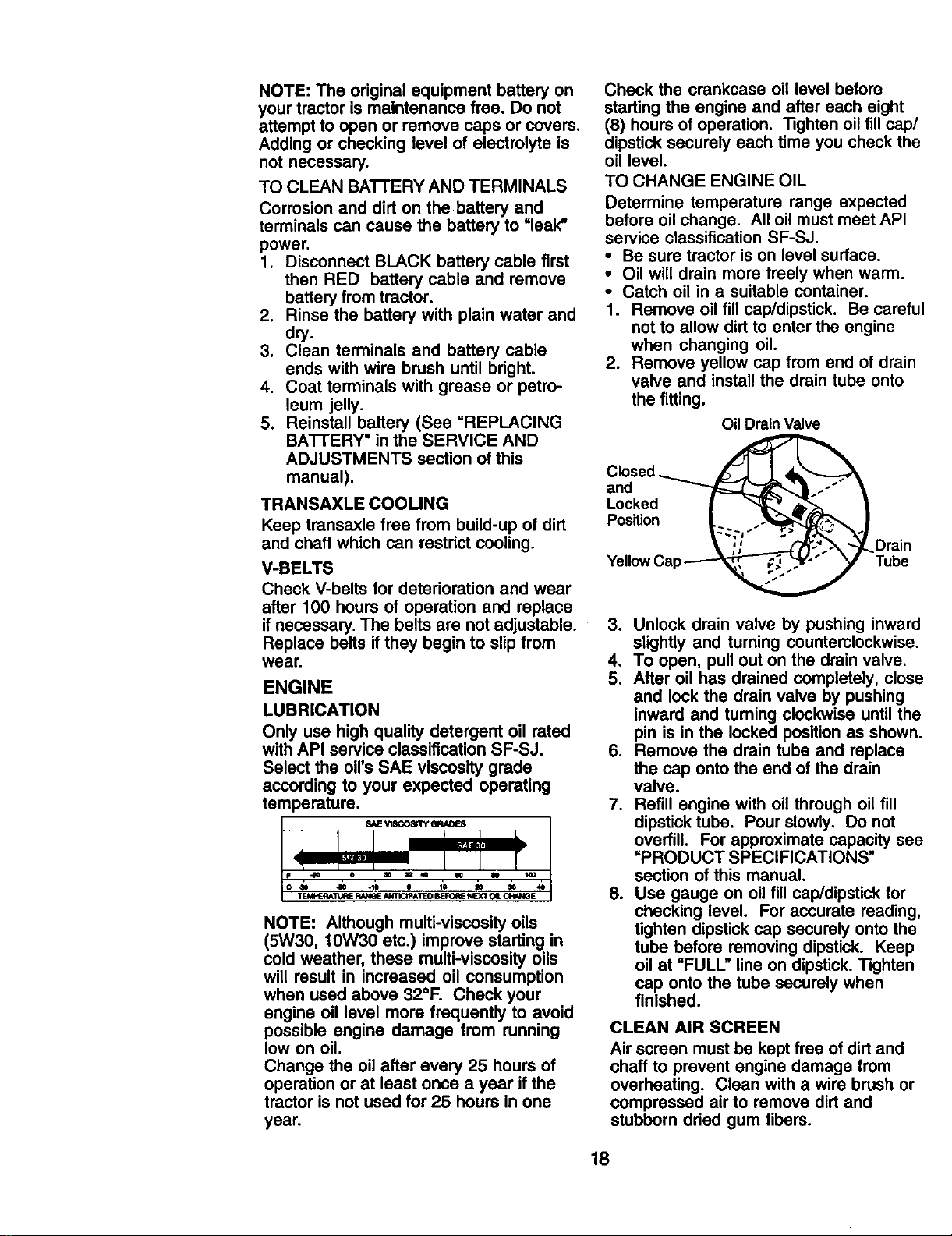
TO CHANGE ENGINE OIL
Determine temperature range expected
before oil change. All oil must meet API
service classification SF-SJ.
• Be sure tractor is on level surface.
• Oil will drain more freely when warm.
• Catch oil in a suitable container.
1. Remove oil fill cap/dipstick. Be careful
not to allow dirt to enter the engine
when changing oil.
2. Remove yellow cap from end of drain
valve and install the drain tube onto
the fitting.
Oil Drain Valve
Closed _
and __l_ .-"
Locked I _ dl,_-._
Position__
YellowCap
lDrain
Tube
3. Unlock drain valve by pushing inward
slightly and turning counterclockwise.
4. To open, pull out on the drain valve.
5. After oil has drained completely, close
and lock the drain valve by pushing
inward and turning clockwise until the
pin is in the locked positionas shown.
6. Remove the drain tube and replace
the cap onto the end of the drain
valve.
7. Refill engine with oil through oil fill
dipstick tube. Pour slowly. Do not
overfill. For approximate capacity see
=PRODUCT SPECIFICATIONS"
section of this manual.
8. Use gauge on oil fill cap/dipstick for
checking level. For accurate reading,
tighten dipstick cap securely onto the
tube before removing dipstick. Keep
oil at "FULL" line on dipstick. Tighten
cap onto the tube securely when
finished.
CLEAN AIR SCREEN
Air screen must be kept free of dirtand
chaff to prevent engine damage from
overheating. Clean with a wire brush or
compressed air to remove dirt and
stubborn dried gum fibers.
18
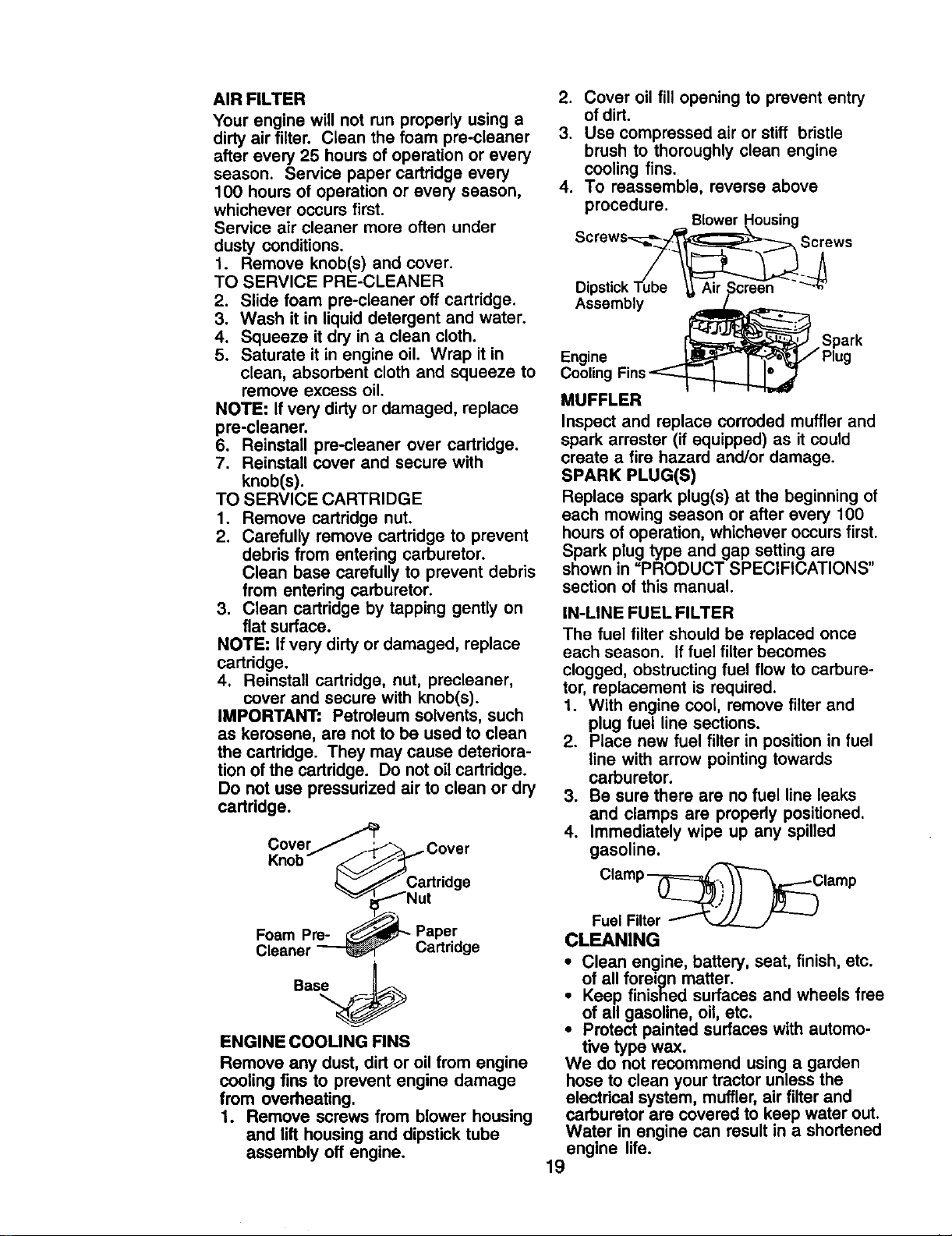
AIR FILTER
Your engine will not run properly using a
dirty air filter. Clean the foam pre-cleaner
after every 25 hours of operation or every
season. Service paper cartridge every
100 hours of operation or every season,
whichever occurs first.
Service air cleaner more often under
dusty conditions.
1. Remove knob(s) and cover.
TO SERVICE PRE-CLEANER
2. Slide foam pre-cleaner off cartridge.
3. Wash it in liquid detergent and water.
4. Squeeze it dry in a clean cloth.
5. Saturate it in engine oil. Wrap it in
clean, absorbent cloth and squeeze to
remove excess oil.
NOTE: If very dirty or damaged, replace
pre-cleaner.
6. Reinstall pre-cleaner over cartridge.
7. Reinstall cover and secure with
knob(s).
TO SERVICE CARTRIDGE
1. Remove cartridge nut.
2. Carefully remove cartridge to prevent
debris from entering carburetor.
Clean base carefully to prevent debris
from entering carburetor.
3. Clean cartridge by tapping gently on
flat surface.
NOTE: if very dirty or damaged, replace
cartridge.
4. Reinstall cartridge, nut, precleaner,
cover and secure with knob(s).
IMPORTANT" Petroleum solvents, such
as kerosene, are not to be used to clean
the cartridge. They may cause deteriora-
tion of the cartridge. Do not oil cartridge.
Do net use pressurized air to clean or dry
cartddge.
KCOV.er..._:r--_ j Cover
nOD _J._Cartridge
"_JI_---"N ut
Foam Pre-_L- PaPer
Cleaner _ Cartridge
Bas_
ENGINE COOLING FINS
Remove any dust, dirt or oil from engine
cooling fins to prevent engine damage
from overheating.
1. Remove screws from blower housing
and lift housing and dipstick tube
assembly off engine.
2. Cover oil fill opening to prevent entry
of dirt.
3. Use compressed air or stiff bristle
brush to thoroughly clean engine
cooling fins.
4. To reassemble, reverse above
procedure.
Blower Housing
Screws'__ _S_rews_
Dipstick Tube _ Air Scre-en "
Assembly
. Spark
Engine _-AIP"_ Tz-_,_,j,f Plug
Cooling Fins_
MUFFLER
Inspect and replace corroded muffler and
spark arrester (if equipped) as it could
create a fire hazard and/or damage.
SPARK PLUG(S)
Replace spark plug(s) at the beginning of
each mowing season or after every 100
hours of operation, whichever occurs first.
Spark plug type and gap setting are
shown in "PRODUCT SPECIFICATIONS"
section of this manual.
IN-LINE FUEL FILTER
The fuel filter should be replaced once
each season. If fuel filter becomes
clogged, obstructingfuel flow to carbure-
tor, replacement is required.
1. With engine cool, remove filter and
plug fuel line sections.
2. Place new fuel filter in position in fuel
line with arrow pointing towards
carburetor.
3. Be sure there are no fuel line leaks
and clamps are properly positioned.
4. Immediately wipe up any spilled
gasoline.
CLEANING
i Clean engine, battery, seat, finish, etc.
of all foreign matter.
Keep finished surfaces and wheels free
of all gasoline, oil, etc.
• Protect painted surfaces with automo-
tive type wax.
We do not recommend using a garden
hose to clean your tractor unless the
electdcal system, muffler, air filter and
carburetor are covered to keep water out.
Water in engine can result in a shortened
engine life.
19
WARNING: TO AVlOD SERIOUS INJURY, BEFORE PERFORMING ANY
1. Depress clutch/brake pedal fully and set parking brake.
2. Place gearshift lever in neutral (N) position.
3. Place attachment clutch in =DISENGAGED" position.
4. Turn ignitionkey to =STOP" and remove key.
5. Make sure the blades and all moving parts have completely stopped.
6. Disconnect spark plug wire from spark plug and place wire where it cannot
come in contact with plug.
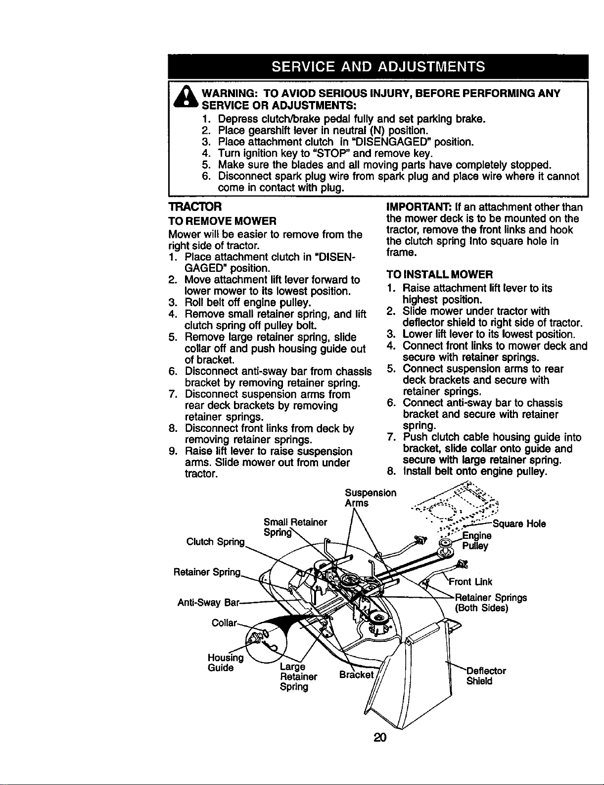
TRACTOR
TO REMOVE MOWER
Mower will be easier to remove from the
rightside oftractor.
1. Place attachment clutch in =DISEN-
GAGED" position.
2. Move attachment lift lever forward to
lower mower to its lowest position.
3. Roll belt off engine pulley.
4. Remove small retainer spring, and lift
clutch spring off pulley bolt.
5. Remove large retainer spring, slide
collar off and push housing guide out
of bracket.
6. Disconnect anti-sway bar from chassis
bracket by removing retainer spring.
7. Disconnect suspension arms from
rear deck brackets by removing
retainer springs.
8. Disconnect front links from deck by
removing retainer springs.
9. Raise lift lever to raise suspension
arms. Slide mower out from under
tractor.
IMPORTANT: If an attachment other than
the mower deck is to be mounted on the
tractor, remove the front links and hook
the clutch spring Into square hole in
frame.
TO INSTALL MOWER
1. Raise attachment liftlever to its
highest position.
2. Slide mower under tractor with
deflector shield to right side of tractor.
3. Lower liftlever to its lowest position.
4. Connect front links to mower deck and
secure with retainer springs.
5. Connect suspension arms to rear
deck brackets and secure with
retainer springs.
6. Connect anti-sway bar to chassis
bracket and secure with retainer
spring.
7. Push clutch cable housing guide into
bracket, slide collar onto guide and
secure with large retainer spring.
8. Install belt onto engine pulley.
Clutch Spdng
Small Retainer
Spdng_
Suspension
Arms
Pulley
Retainer S
Anti-Sway
prings
(Both Sides)
Housing
Guide
Retainer
Spring
Shield
2O
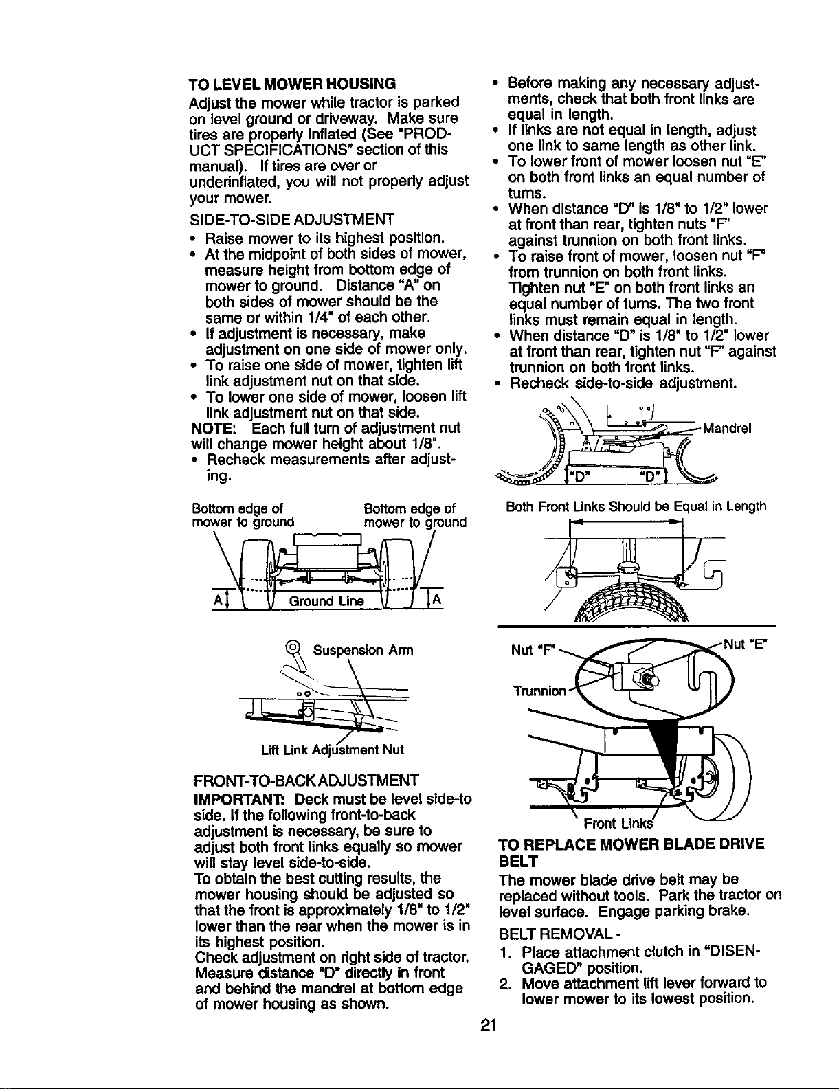
TO LEVEL MOWER HOUSING
Adjust the mower while tractor is parked
on level ground or driveway. Make sure
tires are properly inflated (See =PROD-
UCT SPECIFICATIONS" section ofthis
manual). If tiresare over or
undednflated, you will not properly adjust
your mower.
SIDE-TO-SIDE ADJUSTMENT
• Raise mower to its highest position.
• At the midpointof both sides of mower,
measure height from bottom edge of
mower to ground. Distance "A" on
both sides of mower should be the
same or within 1/4" of each other.
• If adjustment is necessary, make
adjustment on one side of mower only.
• To raise one side of mower, tighten lift
linkadjustment nut on that side.
• To lower one side of mower, loosen lift
linkadjustment nut on that side.
NOTE: Each full turn of adjustment nut
will change mower height about 1/8".
• Recheck measurements after adjust-
ing.
Bottomedge of Bottom edge of
mower to ground mower to ground
• Before making any necessary adjust-
ments, check that both front links are
equal in length.
• If links are not equal in length, adjust
one link to same length as other link.
• To lower front of mower loosen nut "E"
on both front links an equal number of
turns.
• When distance =D" is 1/8" to 1/2" lower
at front than rear, tighten nuts"F"
against trunnion on both front links.
• To raise front of mower, loosen nut "F"
from trunnion on both front links.
Tighten nut =E"on both front links an
equal number of tums. The two front
links must remain equal in length.
• When distance =D"is 1/8" to 1/2=lower
at front than rear, tighten nut =F"against
trunnion on both front links.
• Recheck side-to-side adjustment.
"D"
Both Front Unks Should be Equal in Length
Suspension Arm
FRONT-TO-BACK ADJUSTMENT
IMPORTANT: Deck must be level side-to
side. if the following front-to-back
adjustment is necessary, be sure to
adjust both front links equally so mower
will stay level side-to-side.
To obtain the best cutting results, the
mower housing should be adjusted so
that the front is approximately 1/8" to 112"
lower than the rear when the mower is in
its highest position.
Check adjustment on rightside of tractor.
Measure distance =D_directly in front
and behind the mandrel at bottom edge
of mower housing as shown.
:=E"
Front Links
TO REPLACE MOWER BLADE DRIVE
BELT
The mower blade drive belt may be
replaced without tools. Park the tractor on
level surface. Engage parking brake.
BELT REMOVAL-
1. Place attachment clutch in =DISEN-
GAGED" position.
2. Move attachment lift lever forward to
lower mower to its lowest position.
21
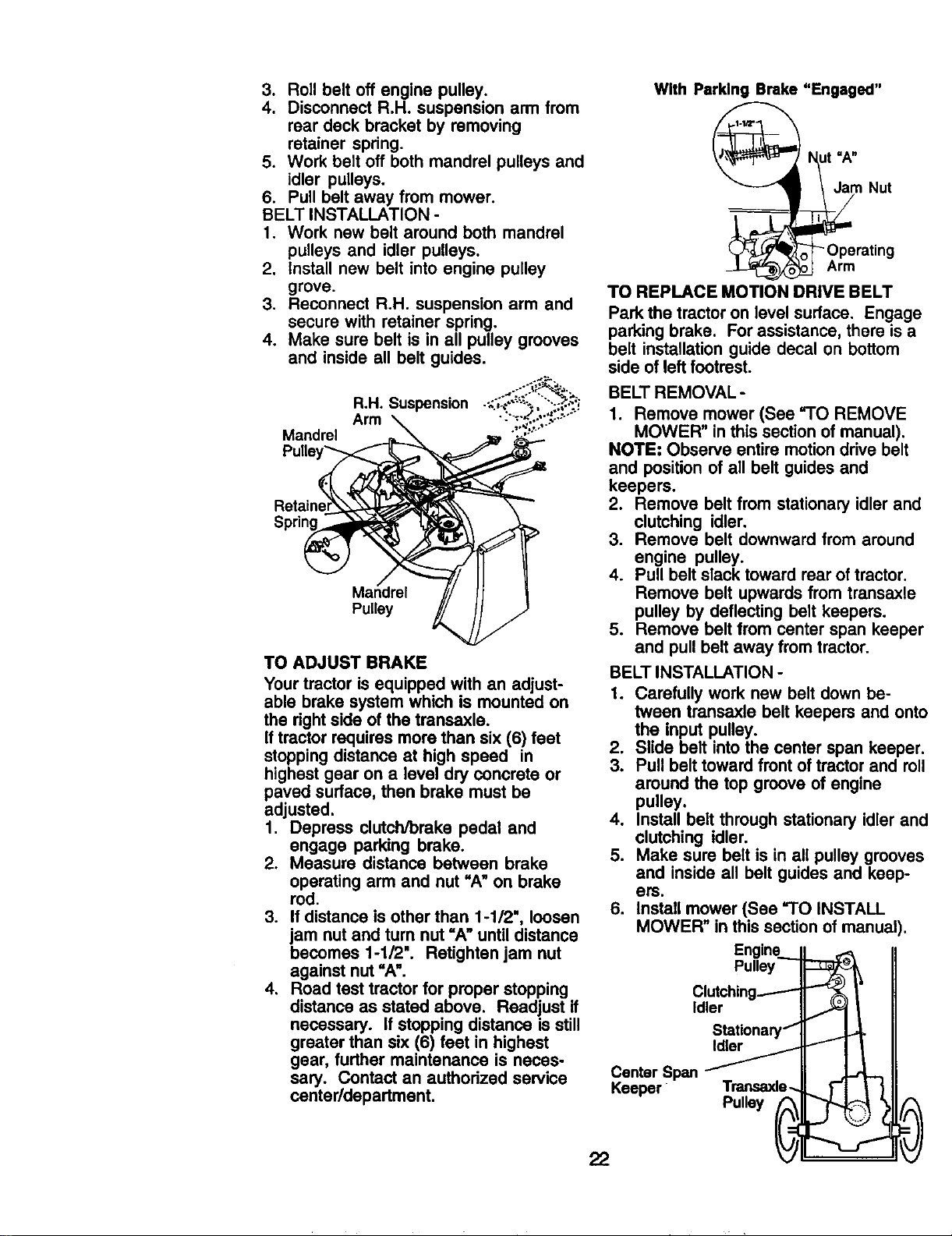
3. Roll belt off engine pulley.
4. Disconnect R.H. suspension arm from
rear deck bracket by removing
retainer spring.
5. Work belt off both mandrel pulleys and
idler pulleys.
6. Pull belt away from mower.
BELT INSTALLATION -
1. Work new belt around both mandrel
pulleys and idler pulleys.
2. Install new belt into engine pulley
grove.
3. Reconnect R.H. suspension arm and
secure with retainer spring.
4. Make sure belt is in all pulley grooves
and inside all belt guides.
R,H. Suspension
Arm
Mandrel
Pulley
TO ADJUST BRAKE
Your tractor is equipped with an adjust-
able brake system which is mounted on
the right side of the transaxle.
If tractor requires more than six (6) feet
stoppingdistance at high speed in
highest gear on a level dry concrete or
paved surface, then brake must be
adjusted.
I. Depress clutch/brake pedal and
engage parking brake.
2. Measure distance between brake
operating arm and nut "A"on brake
rod.
3. If distance is other than 1-1/2', loosen
jam nut and turn nut =A" untildistance
becomes 1-1/2". Retightan jam nut
against nut =A".
4. Road test tractor for proper stopping
distance as stated above. Readjust if
necessary. If stopping distance is still
greater than six (6) feet in highest
gear, further maintenance is neces-
sary. Contact an authorized service
center/department.
With Parking Brake "Engaged"
i_mt=A"
Nut
-Operating
Arm
TO REPLACE MOTION DRIVE BELT
Park the tractor on level surface. Engage
parking brake. For assistance, there is a
belt installation guide decal on bottom
side of left footrest.
BELT REMOVAL -
1. Remove mower (See "1"OREMOVE
MOWER" in this section of manual).
NOTE: Observe entire motiondrive belt
and position of all belt guides and
keepers.
2. Remove belt from stationary idlerand
clutching idler.
3. Remove belt downward from around
engine pulley.
4. Pull belt slack toward rear oftractor.
Remove belt upwards from transaxle
pulley by deflecting belt keepers.
5. Remove belt from center span keeper
and pull belt away from tractor.
BELT INSTALLATION -
1. Carefully work new belt down be-
tween transaxle belt keepers and onto
the input pulley.
2. Slide belt intothe center span keeper.
3. Pull belt toward front of tractor and roll
around the top groove of engine
pulley.
4. Install belt through stationary idler and
clutching idler.
5. Make sure belt is in all pulley grooves
and inside all belt guides and keep-
ers.
6. Install mower (See "TO INSTALL
MOWER" in this section of manual).
Engine..__
Pulley
Clutching_
Idler
StationaryI"
IdlerF
Center Span
Keeper Transaxle._
Pulley _
22
J
TO ADJUST STEERING WHEEL ALIGN-
MENT
if steering wheel crossbars are not
hodzontal (left to right) when wheels are
positioned straight forward, remove
steering wheel and reassemble with
crossbars horizontal. Tighten securely.
FRONT WHEEL TOE-IN/CAMBER
The front wheel toe-in and camber are
not adjustable on your tractor. If damage
has occurred to affect the front wheel toe-
in or camber, contact your nearest
authorized service center/department.
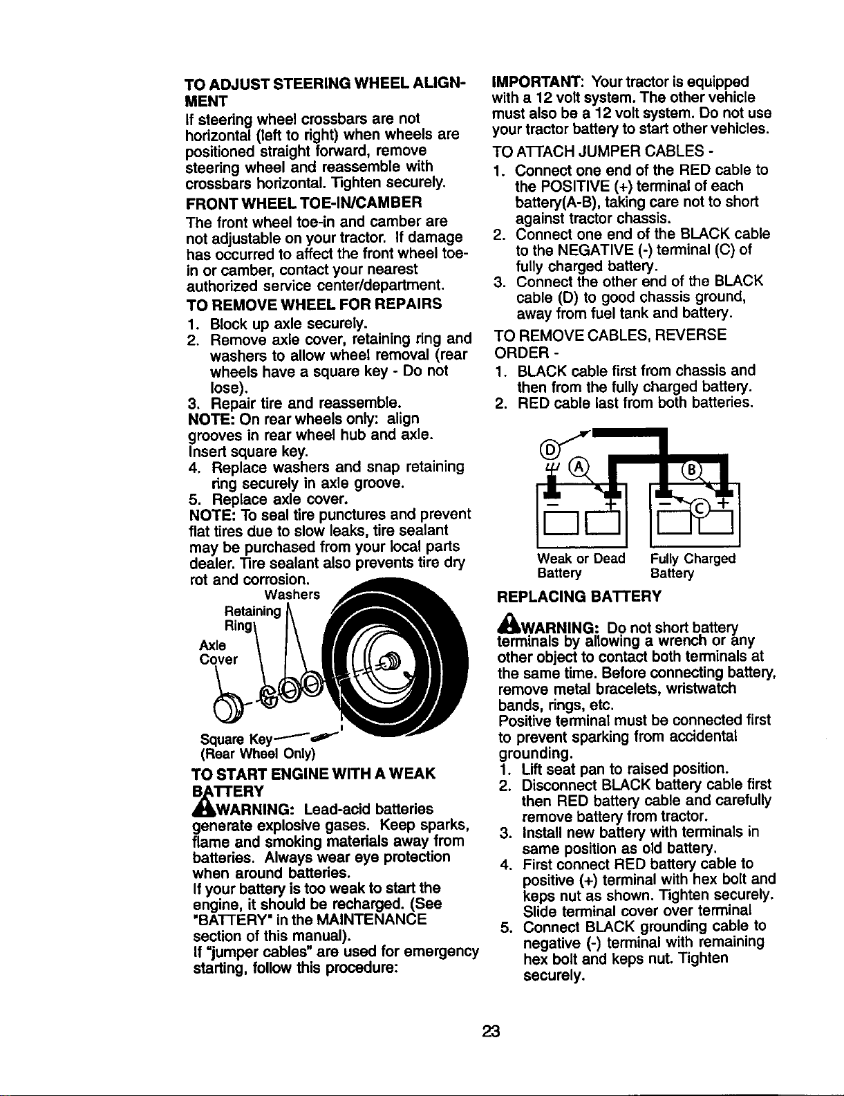
TO REMOVE WHEEL FOR REPAIRS
1. Block up axle securely.
2. Remove axle cover, retaining ring and
washers to allow wheel removal (rear
wheels have a square key - Do not
lose).
3. Repair tire and reassemble.
NOTE: On rear wheels only: align
grooves in rear wheel hub and axle.
Insert square key.
4. Replace washers and snap retaining
ring securely in axle groove.
5. Replace axle cover.
NOTE: To seal tire punctures and prevent
flat tires due to slow leaks, tire sealant
may be purchased from your local parts
dealer. Tire sealant also prevents tire dry
rot and corrosion.
Washers
Retaining
Axle
Cover
Square Key_'"
(Rear Wheel Only)
TO START ENGINE WITH A WEAK
_TTAE RY
RNING: Lead-acid batteries
generate explosive gases. Keep sparks,
flame and smoking materials away from
batteries. Always wear eye protection
when around batteries.
If your battery is too weak to start the
engine, it should be recharged. (See
"BATTERY" in the MAINTENANCE
section of this manual).
If =jumper cables" are used for emergency
starting, follow this procedure:
IMPORTANT: Your tractor is equipped
with a 12 volt system. The other vehicle
must also be a 12 volt system. Do not use
your tractor battery to start other vehicles.
TO A'I-FACH JUMPER CABLES -
1. Connect one end of the RED cable to
the POSITIVE (+) terminal of each
battery(A-B), taking care not to short
against tractor chassis.
2. Connect one end of the BLACK cable
to the NEGATIVE (-) terminal (C) of
fully charged battery.
3. Connect the other end of the BLACK
cable (D) to good chassis ground,
away from fuel tank and battery.
TO REMOVE CABLES, REVERSE
ORDER -
1. BLACK cable first from chassis and
then from the fully charged battery.
2. RED cable last from both batteries.
B
Weak or Dead Fully Charged
Battery Battery
REPLACING BATTERY
x't
_WA,RN.ING: Do not short battery
terminals oy allowing a wrencn or any
other object to contact both terminals at
the same time. Before connecting battery,
remove metal bracelets, wristwatch
bands, dngs, etc.
Positive terminal must be connected first
to prevent sparking from accidental
grounding.
1. Lift seat pan to raised position.
2. Disconnect BLACK battery cable first
then RED battery cable and carefully
remove battery from tractor.
3. Install new battery with terminals in
same position as old battery.
4. First connect RED battery cable to
positive (+) terminal with hex bolt and
keps nut as shown. Tighten securely.
Slide terminal cover over terminal
5. Connect BLACK grounding cable to
negative (-) terminal with remaining
hex bolt and keps nut. Tighten
securely.
23
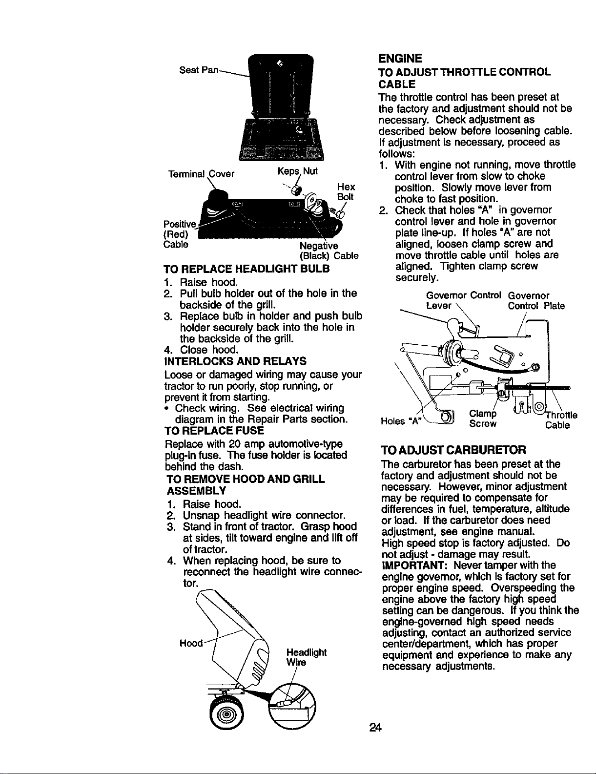
Terminal
Nut
Hex
Bolt
Positive
(Red)
Cable Negative
(Black) Cable
TO REPLACE HEADLIGHT BULB
1. Raise hood.
2. Pull bulb holder out of the hole in the
backside of the grill.
3. Replace bulb in holder and push bulb
holder securely back into the hole in
the backside of the grill.
4. Close hood.
INTERLOCKS AND RELAYS
Loose or damaged wiring may cause your
tractor to run poorly, stop running, or
prevent itfrom starting.
• Check wiring. See electrical wiring
diagram in the Repair Parts section.
TO REPLACE FUSE
Replace with 20 amp automotive-type
plug-in fuse. The fuse holder is located
behind the dash.
TO REMOVE HOOD AND GRILL
ASSEMBLY
1. Raise hood.
2. Unsnap headlight wire connector.
3. Stand in front of tractor. Grasp hood
at sides, tilt toward engine and lift off
of tractor.
4. When replacing hood, be sure to
reconnect the headlight wire connec-
tor.
Headlight
Wire
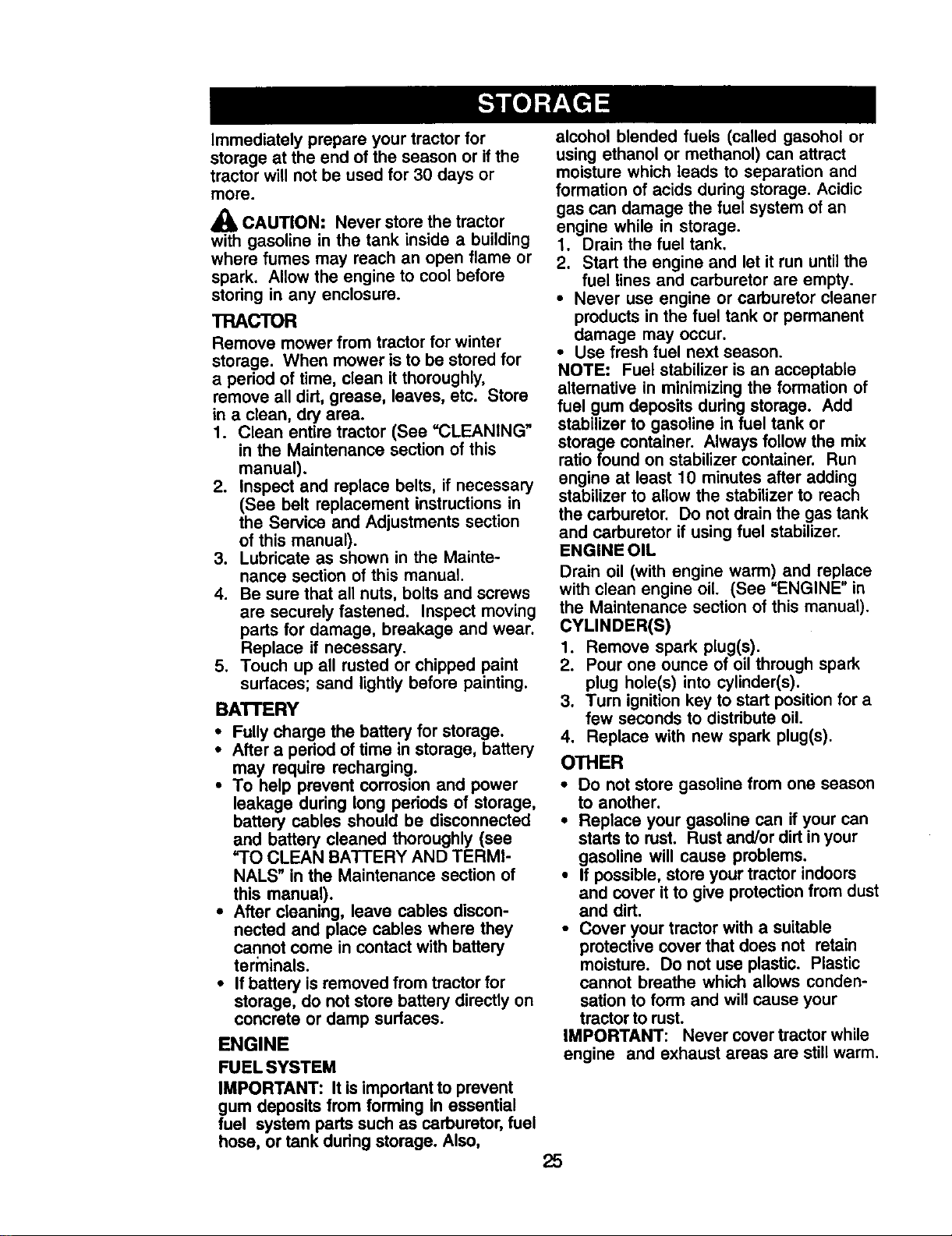
ENGINE
TO ADJUST THRO'I-I'LE CONTROL
CABLE
The throttle control has been preset at
the factory and adjustment should not be
necessary. Check adjustment as
described below before loosening cable.
If adjustment is necessary, proceed as
follows:
1. With engine not running, move throttle
control lever from slow to choke
position. Slowly move lever from
choke to fast position.
2. Check that holes =A" in governor
control lever and hole in governor
plate line-up. If holes "A" are not
aligned, loosen clamp screw and
move throttle cable until holes are
aligned. Tighten clamp screw
securely.
Governor Control Governor
Control Plate
\
Holes Screw Cable
TO ADJUST CARBURETOR
The carburetor has been preset at the
factory and adjustment should not be
necessary. However, minor adjustment
may be required to compensate for
differences in fuel, temperature, altitude
or load. If the carburetordoes need
adjustment, see engine manual.
High speed stop is factoryadjusted. Do
not adjust - damage may result.
IMPORTANT: Never tamper with the
engine govemor, which isfactory set for
proper engine speed. Overspeeding the
engine above the factory high speed
setting can be dangerous. If you think the
engine-governed high speed needs
adjusting, contact an authorized service
center/department, which has proper
equipment and experience to make any
necessary adjustments.
24
Immediately prepare your tractor for
storage at the end of the season or ifthe
tractor will not be used for 30 days or
more.
_lb CAUTION: Never store the tractor
with gasoline in the tank inside a building
where fumes may reach an open flame or
spark. Allow the engine to cool before
storing in any enclosure.
TRACTOR
Remove mower from tractor for winter
storage. When mower is to be stored for
a period of time, clean itthoroughly,
remove all dirt, grease, leaves, etc. Store
in a clean, dry area.
1. Clean entire tractor (See =CLEANING"
in the Maintenance section of this
manual).
2. Inspect and replace belts, if necessary
(See belt replacement instructionsin
the Service and Adjustments section
of this manual).
3. Lubricate as shown in the Mainte-
nance section of this manual.
4. Be sure that all nuts, bolts and screws
are securely fastened. Inspect moving
parts for damage, breakage and wear.
Replace if necessary.
5. Touch up all rusted or chipped paint
surfaces; sand lightly before painting.
BA'I'rERY
• Fully charge the battery for storage.
• After a period of time in storage, battery
may require recharging.
• To help prevent corrosion and power
leakage during long periods of storage,
battery cables should be disconnected
and battery cleaned thoroughly (see
=TO CLEAN BATTERY AND TERMI-
NALS" in the Maintenance section of
this manual).
• After cleaning, leave cables discon-
nected and place cables where they
cannot come in contact with battery
terminals.
• If battery is removed from tractor for
storage, do not store battery directly on
concrete or damp surfaces.
ENGINE
FUEL SYSTEM
IMPORTANT: It is important to prevent
gum deposits from forming In essential
fuel system parts such as carburetor, fuel
hose, or tank during storage. Also,
alcohol blended fuels (called gasohol or
using ethanol or methanol) can attract
moisture which leads to separation and
formation of acids during storage. Acidic
gas can damage the fuel system of an
engine while in storage.
1. Drain the fuel tank.
2. Start the engine and let it run until the
fuel lines and carburetor are empty.
• Never use engine or carburetor cleaner
products in the fuel tank or permanent
damage may occur.
• Use fresh fuel next season.
NOTE: Fuel stabilizer is an acceptable
alternative in minimizing the formation of
fuel gum deposits during storage. Add
stabilizer to gasoline in fuel tank or
storage container. Always follow the mix
ratio found on stabilizer container. Run
engine at least 10 minutes after adding
stabilizer to allow the stabiUzer to reach
the carburetor. Do not drain the gas tank
and carburetor if using fuel stabilizer.
ENGINE OIL
Drain oil (with engine warm) and replace
with clean engine oil (See =ENGINE" in
the Maintenance section of this manual).
CYLINDER(S)
1. Remove spark plug(s).
2. Pour one ounce of oil through spark
plug hole(s) into cylinder(s).
3. Turn ignition key to start position for a
few seconds to distdbute oil.
4. Replace with new spark plug(s).
OTHER
• Do not store gasoline from one season
to another.
• Replace your gasoline can if your can
starts to rust. Rust and/or dirt in your
gasoline will cause problems.
• If possible, store your tractor indoors
and cover it to give protection from dust
and dirt.
• Cover your tractor with a suitable
protective cover that does not retain
moisture. Do not use plastic. Plastic
cannot breathe which allows conden-
sation to form and will cause your
tractor to rust.
IMPORTANT: Never cover tractor while
engine and exhaust areas are still warm.
25
TROUBLESHOOTING CHART
PROBLEM CAUSE
Willn_stad
Hard to start
Enginewlll not
turn over
Engine clicks but
will not start
• Out offuel.
• Engine not "CHOKED" •
properl_
• Engine flooded.
• Bad spark plug.
• Dirty air filter.
• Dirty fuel filter.
• Water in fuel.
• Loose or damaged wiring. •
• Carburetor out of adjustment •
Engine valves out of
adjustment.
• Dirty air filter.
• Bad spark plug.
• Weak or dead battery.
• Dirty fuel filter.
• Stale or dirty fuel.
• Loose or damaged wiring.
• Carburetor out of adjustment.
Engine valves out of
adjustment.
CORRECTION
Clutch/brake pedal not
Fillfuel tank.
See "TO START ENGINE"
in Operation section.
Wait several minutes
before attemptingto start.
Replace spark plug.
Clean/replace air filter.
Replace fuel filter.
Drain fuel tank and
carburetor, refilltank with
fresh gasoline and replace
fuel filter.
Check all wiring.
See "To Adjust Carburetor"
in Service Adjustments
section.
Contact an authorized
service center/department.
• Clean/replace air filter.
• Replace spark plug.
• Recharge or replace
battery.
• Replace fuel filter.
• Drain fuel tank and refill
with fresh gasoline.
• Check all wiring.
• See "To Adjust Carburetor"
in Service Adjustments
section.
• Contact an authorized
service center/department.
Depress clutch/brake
depressed.
• Attachment clutch is
engaged.
• Weak or dead battery,
• Blown fuse.
pedal.
• Disengage attachment
clutch.
• Recharge or replace
battery.
• Replace fuse.
Corroded battery terminals.
Loose or damaged wiring.
Faulty solenoid or starter,
Faulty operator presence
switch(es).
• Weak or dead battery.
• Corroded battery terminals.
• Loose or damaged wiring.
• Faulty solenoid or starter.
• Clean battery terminals.
• Check/replace ignition
switch.
• Check/replace solenoid or
starter.
• Contact an authorized
service center/department.
• Recharge or replace battery
• Clean battery terminals.
• Check all widng.
• Check/replace solenoid or
starter.
26
TROUBLESHOOTING CHART
CAUSE
• Cutting too much grass/too
fast.
• Throttle in "CHOKE"
position.
• Build-up of grass, leaves
and trash under mower.
• Dirty air filter.
• Low oil level/dirty oil.
• Faulty spark plug.
PROBLEM
Lossofpower
• Dirty fuel filter.
• Stale or dirty fuel.
• Water in fuel.
• Spark plug wire loose.
• Dirty engine air screen/fins.
• Dirty/clogged muffler.
• Loose or damaged wiring.
• Carburetor out of
adjustment.
Excessive
vibration
Engine continues •
to run
when operator
leaves seat with
with attachment
ciutch engaged
Poor cut- uneven •
Engine valves out of
adjustment.
Worn, bent or loose blade.
Bent blade mandrel.
Loose/damaged part(s).
Faulty operator-safety
presence control system.
Wom, bent or loose blade.
Mower deck not level.
Buildup of grass, leaves,
and trash under mower.
Bent blade mandrel.
Clogged mower deck vent
holes from buildup of
grass, leaves, and trash
around mandrels.
CORRECTION
• Set in =Higher Cut" position/
reduce speed.
• Adjust throttle control.
• Clean underside of mower
housing.
• Clean/replace air filter.
• Check oil level/change oil.
• Clean and regap or change
spark plug.
• Replace fuel filter.
• Drain fuel tank and refill with
fresh gasoline.
• Drain fuel tank and carbure-
tor, refill tank with fresh
gasoline and replace fuel
filter.
• Connect and tighten spark
plug wire.
• Clean engine air screen/fins.
• Clean/replace muffler.
• Check all wiring.
• See "To Adjust Carburetor"
in Service Adjustments
section.
• Contact an authorized
service center/department.
• Replace blade.
Tighten blade bolt.
• Replace blade mandrel.
• Tighten loose part(s).
Replace damaged parts.
Check wiring, switches and
connections. If not corrected
contact an authorized
service center/department.
• Replace blade. Tighten
blade bolt.
• Level mower deck.
• Clean underside of mower
housing.
• Replace blade mandrel.
• Clean around mandrels to
open vent holes.
27
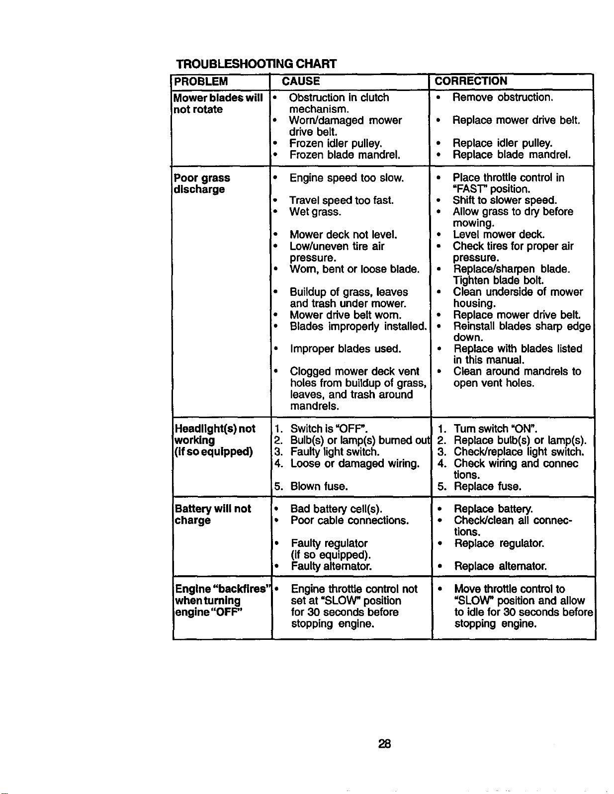
PROBLEM
Mower blades will
not rotate
TROUBLESHOOTING CHART
CAUSE
• Obstruction in clutch
mechanism.
Poor grass
discharge
Headlight(s) not
working
(if so equipped)
Battery will not
charge
Engine "backfires'
whentuming
engine "OFF"
• Worn/damaged mower
drive belt.
• Frozen idler pulley.
• Frozen blade mandrel.
• Engine speed too slow.
• Travel speed too fast.
• Wet grass.
• Mower deck not level,
• Low/uneven tire air
pressure.
• Wom, bent or loose blade.
• Buildup of grass, leaves
and trash under mower.
• Mower drive belt worn.
• Blades improperly installed,
• Improper blades used.
Clogged mower deck vent
holes from buildup of grass,
leaves, and trash around
mandrels.
1. Switch is=OFF".
2. Bulb(s) or lamp(s) bumed out
3. Faulty lightswitch.
4. Loose or damaged wiring.
5. Blown fuse.
• Bad battery cell(s).
• Poor cable connections.
• Faulty regulator
(if so equipped).
• Faulty altemator.
Engine throttle control not
set at =SLOW" position
for 30 seconds before
stopping engine.
CORRECTION
• Remove obstruction.
• Replace mower drive belt.
• Replace idler pulley.
• Replace blade mandrel.
• Place throttle controlin
=FAST" position.
• Shift to slower speed.
• Allow grass to dry before
mowing.
• Level mower deck.
• Check tires for proper air
pressure.
• Replace/sharpen blade.
Tighten blade bolt,
• Clean underside of mower
housing.
• Replace mower drive belt.
• Reinstall blades sharp edge
down.
• Replace with blades listed
in this manual.
• Clean around mandrels to
open vent holes.
1. Turn switch =ON".
2. Replace bulb(s) or lamp(s).
3. Check/replace light switch.
4. Check wiring and connec
tions.
5. Replace fuse.
• Replace battery,
,. Check/clean all connec-
tions.
• Replace regulator.
• Replace altemator,
Move throttle control to
"SLOW" position and allow
to idle for 30 seconds befor=
stopping engine.
28
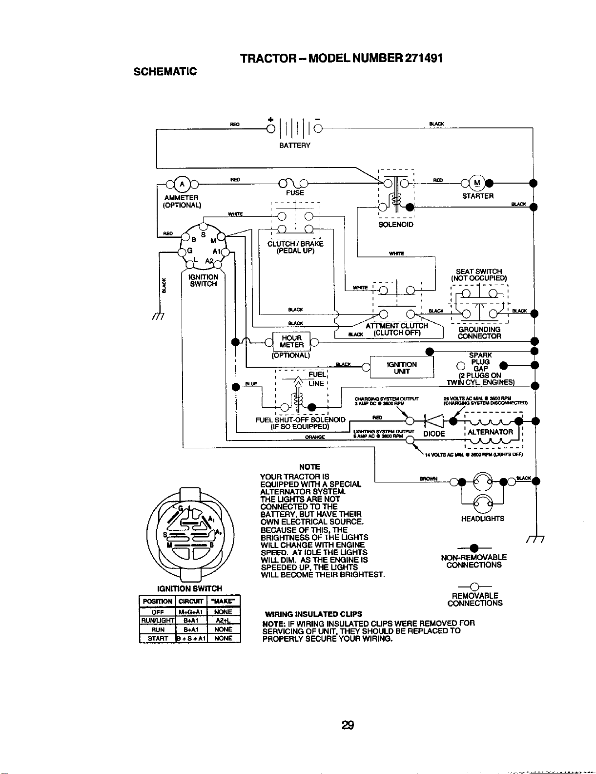
TRACTOR - MODEL NUMBER 271491
SCHEMATIC
REO
BATTERY
REO
AMMETER
(OPTIONAL)
IGNITION
SWITCH
IGNmON SWITCH
SOLENOID
mACK (CLUTCH OFF)
eu_ _ IGNITION
STARTER
SEATSWITCH
(NOTCCCUPIED)
SPARK
____@ PLUG
GAP
2 PLUGSON
TWI_ CYL ENGINES)
HEADLIGHTS
---e--
NON-REMOVABLE
CONNECTIONS
REMOVABLE
CONNECTIONS
NOTE
YOUR TRACTOR IS
EQUIPPED WiTH A SPECIAL
ALTERNATOR SYSTEM.
THE UGHTS ARE NOT
CONNECTED TO THE
BATTERY, BUT HAVE THEIR
OWN ELECTRICAL SOURCE.
BECAUSE OF THIS, THE
BRIGHTNESS OF THE UGHTS
WILL CHANGE WITH ENGINE
SPEED. AT IDLE THE LIGHTS
WILL DIM. AS THE ENGINE IS
SPEEDED UP, THE LIGHTS
WILL BECOME THEIR BRIGHTEST.
F,
WIRING INSULATED CLIPS
NOTE: IF WIRING INSULATED CLIPS WERE REMOVED FOR
SERVICING OF UNIT, THEY SHOULD BE REPLACED TO
PROPERLY SECURE YOUR WIRING.
29
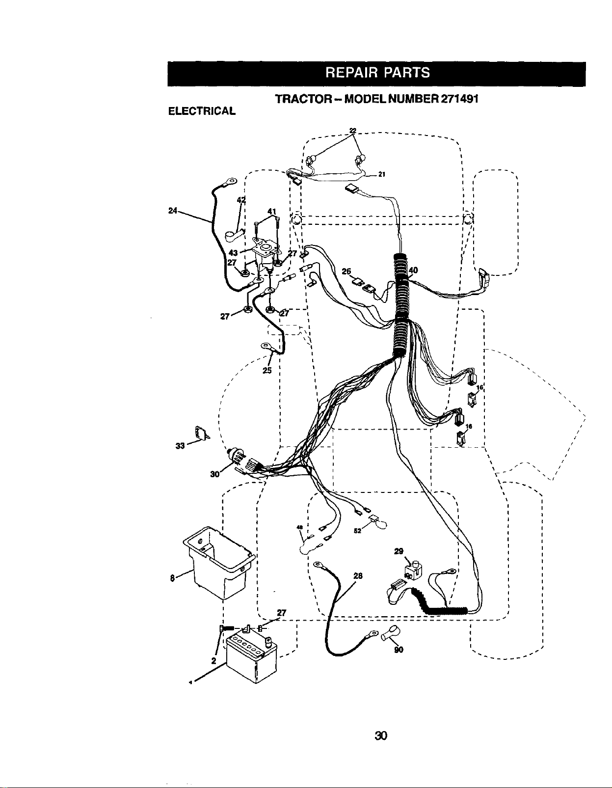
TRACTOR - MODEL NUMBER 271491
ELECTRICAL
26
25
• I
/ I
I I
I I
I I
I 1
I
I
I
I
r
i
i
i
t
i
i
I I
t I
I_ t
II
I i
I
I
I
I
I
I
I
I
/
//
i \ /I
__J
I
I
I
I
3O
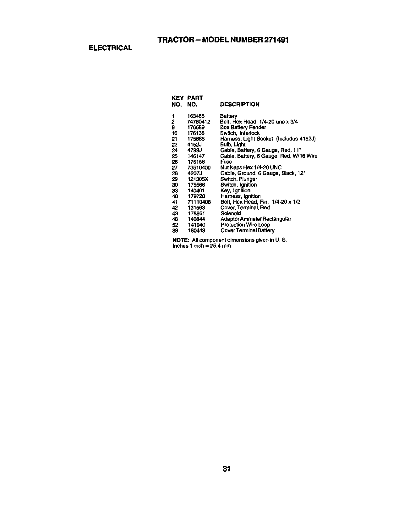
TRACTOR - MODEL NUMBER 271491
ELECTRICAL
KEY PART
NO. NO. DESCRIPTION
1 163465 Battery
2 74760412 Bolt, Hex Head 1/4-20 unc x 3/4
8 176689 Box BatteryFender
16 176138 Switch, Intedock
21 175685 Harness, Ught Socket (InCludes4152J)
22 4152J Bulb, Light
24 4799J Cable, Battery,6 Gauge, Red, 11•
25 146147 Cable, Battery,6 Gauge, Red, W/16 Wire
26 175158 Fuse
27 73510400 Nut KepsHex 1/4-20 UNC
28 4207J Cable, Ground, 6 Gauge, Black, 12"
29 121305X Switch,Plunger
30 175566 Switch, Ignition
33 140401 Key, Ignition
40 179720 Harness, Ignition
41 71110408 Bolt,Hex Head, Fin. 1/4-20 x 1/2
42 131563 Cover,Terminal, Red
43 178861 Solenoid
48 140844 AdaptorAmmeterRectangular
52 141940 ProtectionWire Loop
89 180449 CoverTerminal Battery
NOTE: All componentdimensionsgiven in U. S.
inches I inch= 25.4 mm
31
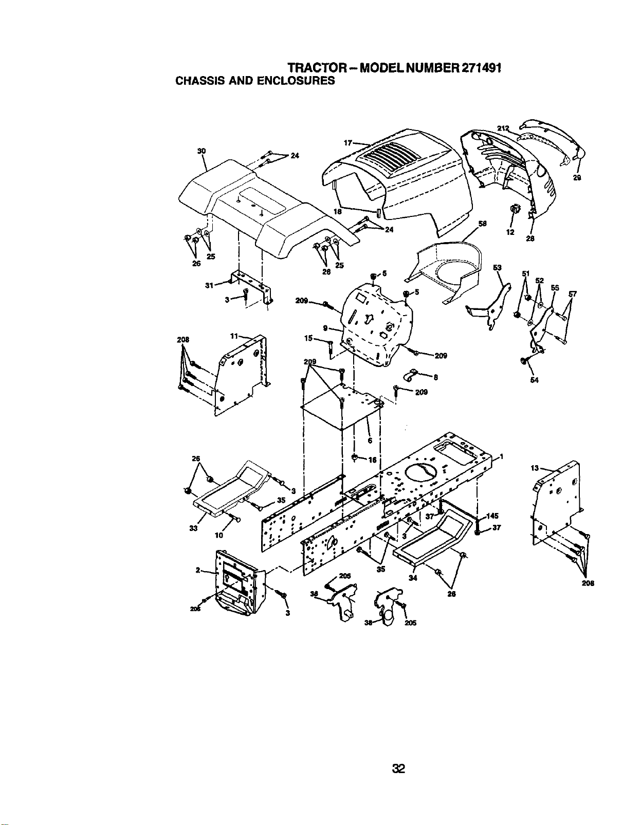
TRACTOR- MODEL NUMBER 271491
CHASSIS AND ENCLOSURES
29
2O8
lO
3S
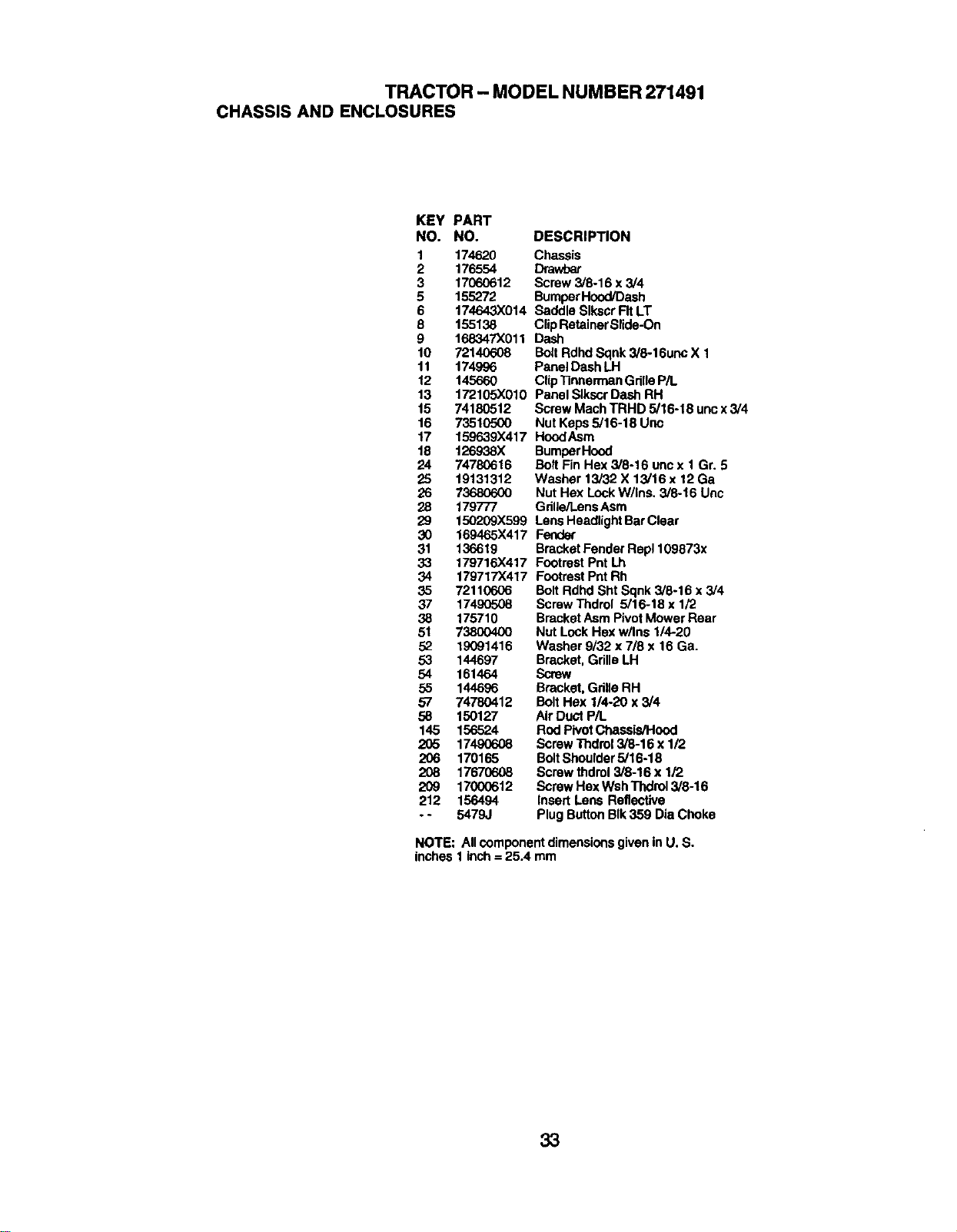
TRACTOR - MODEL NUMBER 271491
CHASSIS AND ENCLOSURES
KEY PART
NO. NO. DESCRIPTION
1 174620 Chassis
2 176554 Drawbar
3 17060612 Screw 3/8-16 x 3/4
5 155272 BumperHood/Dash
6 174643X014 Saddle Slkocr FitLT
8 155138 ClipRetainerSlide-On
9 168347X011 Dash
10 72140608 Bolt Rdhd Sqnk3/8-16unc X 1
11 174996 Panel DashLH
12 145660 ClipTinnerman GdlleP/L
13 172105X010 Panel SIkscr Dash RH
t5 74180512 Screw Mach TRHD 5/16-18 unc x 3/4
16 73510500 Nut Keps5/16-18 Uric
17 159639X417 HoodAsm
18 126938X BumperHood
24 74780616 Bolt Fin Hex 3/8-16 uncx 1 Gr. 5
25 19131312 Washer 13/32 X 13/16 x 12 Ga
26 73680600 Nut Hex LockW/Ins. 3/8-16 Unc
28 179777 Gdlle/l.ensAsm
29 150209X599 LensHeadlightBarClear
30 169465X417 Fender
31 136619 BracketFenderRep1109873x
33 179716X417 Footrest Pnt Lh
34 179717X417 Footrest Pnt Rh
35 72110606 BoltRdhd Sht Sqnk 3/8-16 x 3/4
37 17490508 Screw Thdrol 5/16-18 x 1/2
38 175710 Bracket AsmPivotMower Rear
51 73800400 Nut LockHex w/Ins 1/4-20
52 19C91416 Washer 9/32 x 7/8 x 16 Ga.
53 144697 Bracket, Grille LH
54 161464 Screw
55 144696 Bracket,Grille RH
57 74780412 Bolt Hex 1/4-20 x 3/4
58 150127 Air Duct PiL
145 156524 Rod PivotChassis/Hood
205 17490608 Screw Thdrol 3/8-16 x 1/2
206 170165 BoltShoulder5/16-18
208 17670608 Screw thdrol3/8-16 x 1/2
209 17000612 Screw HexWsh Thdrol3/8-16
212 156494 Insert Lens Reflective
. - 5479J Plug ButtonBIk359 Dia Choke
NOTE: All component dimensionsgiven in U. S.
inches 1 inch = 25.4 mm
33
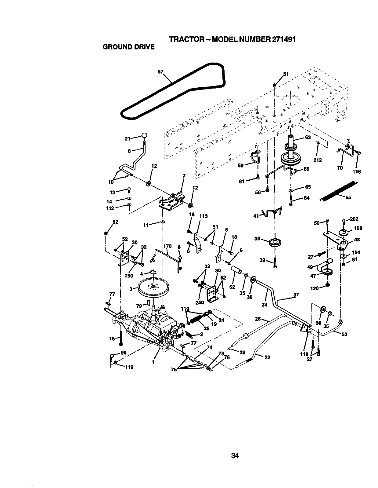
TRACTOR- MODELNUMBER271491
GROUNDDRIVE
i
119
27
34

TRACTOR- MODELNUMBER271491
GROUNDDRIVE
KEY PART
NO. NO.
1 ......
2 146682
3 123666X
4 12000028
5 121520X
6 1706G512
7 162240
8 131679
10 76020416
11 105701X
12 19151216
13 74550412
14 10040400
15 74490544
18 74780616
19 73800600
21 106933X
22 130804
24 73350600
25 106888X
27 76020412
28 175765
29 71673
30 174973
-'_ 74760512
34 175578
35 120183X
36 19211616
37 1572H
38 179114
39 74760648
41 175556
47 127783
48 154407
49 123205X
KEY PART
DESCRIPTION NO, NO.
Transaxle DanaD4360-139 50 74760624
(Order partstram transaxle 51
Manufacturer) 52 73680500
Spring Return Brake T/a Zinc 53 105710X
Pulley Tran_'de 18,'20"tiras 55 105709X
RingRetainer# 5100-62 56 17060620
StrapTorque 30 Degrees 57 160855
Screw 5,'16-18 x 3/4 59 169691
Bracket Saddle ShiftT/a 61 17120614
RodShf Sdl LY/YT Str BIk (_2 8883R
PinCotter 1/6 x I Cad 63 175410
Washer Plate388 Sq Hole 64 71170764
Washer 15/32 x 3/4 x 16ga 65 10040700
Bolt 114-28unfGr8 W/Patch 66 154778
Washer LockHvy Helical 1/4 70 134683
BoltHex Flghd 5/16-18 x Gr. 5 74 109502X
BoltFin Hex 3/8-16 UNC x 1 Gr. 5 75 121749)(
Nut Lock Hex W/Ins. 3/8-16 Unc 76 12000001
Knob Rd 1/2-13 PlstcThds 77 123583X
Rod Blake BIk Zinc26 840 78 121748)(
Nut Hex Jam 3/8-16 Unc 79 2228M
Spring RodBrake 2 00 Zinc 96 4497H
Pin Cotter 1/8 x 3/4 Cad 112 19091210
Rod Brake Parking Lt/Yt 113 127285X
Cap Brake Parking 116 72140608
Bracket MtgTransaxle 119 19131016
BoltHex Hd 5/16-18unc x 3/4 120 73900600
ShaftAsm Pedal Foot Nibbed 150 175456
BearingNylon BIk629 Id 151 19133210
Washer 21/32 x 1 x 16 Ga 176 178394
PinRoll 3/16 X 1" 202 72110614
PulleyComposite Flat 212 145212
BoltFin Hex 3/6-16 UNC x 3 Gr. 5 250 17060612
Keeper Belt Idler
PulleyIdler V Groove Plastic
Bollcrank Asm.Clutch
Retainer Belt Style Spring
DESCRIPTION
BoltHex Hd 3/8-16unc x1-1/2
HutCrowniock 3/6-16 UNC
Nut CrownLock5/16-16
LinkClutch7 66
Sp_ng ReturnClutch 6 75
Screw 3/8-16 x 1-1/4
V-Belt Gd Drive 9530
Keeper BeltCentarspen
Screw 3/6-16 x .875
Cover Pedal BlkRound
PulleyEng CICable
Bolt Hex 7/16-20 x 4 Gr 5
Washer LockHid Spr 7/16
Kceper Belt EngineFP
Guide BeltMower DdveRH
Spacer Axle
Washer 25/32 x 1-1/4 x16 Ga
E-dng#5133-75
Key Square 2 0 x 1845/1865
Washer 25/32 x1-5/8 x 16 Ga
KeyWoodruff #9 3/16 x 3/4
RetainerSpring 1
Washer 9/32 x 3/4 x 10 Ga
StrapTorque LHLT
Bolt3/8-16 x 1
Washer 13/32 x 5/8 x 16 Ga
Nut LockFig 3/8-16
SpacerRetainer
Washer 13/32 x 2 x 10 Ga.
Keeper Belt Traneaxle Gear
Bolt Cart. Sh 3/8-16 x 1-3/4 Gr. 5
Nut Hax Flange Lock
Screw 3/8-16 x 3/4
NOTE: Ancompt_nt dimensionsgiven in U. S.
inches 1 inch= 25.4 mm
35

TRACTOR- MODELNUMBER271491
STEERING
s _ .
t," i, _ •
• _ ___'_1 I
t i
°J
.J
°J
\
i
\
i
\
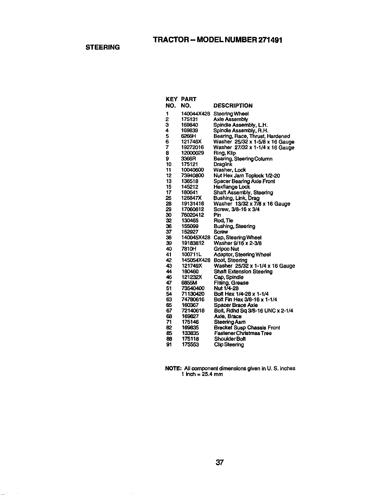
TRACTOR- MODEL NUMBER 271491
STEERING
KEY PART
NO. NO. DESCRIPTION
1 140044X428 SteodngWheel
2 175131 Axle Assembly
3 169840 Spindle Assembly,LH.
4 16,9839 SpindleAssembly, R.H.
5 6266H Bearing, Race, Thrust,Hardened
6 121748)( Washer 25/32 x 1-5/6 x 16 Gauge
7 19272016 Washer 27/32 x 1-1/4 x 16 Gauge
8 12000029 Ring,Klip
9 3366R Beadng,SteedngColumn
10 175121 Dmglink
11 10040600 Washer, Lock
12 73940800 Nut Hex Jam Toplock1/2-20
13 136518 Spacer Beadng Axle Front
15 145212 Hexflange Lock
17 180641 Shaft Assembly, Stoedng
26 126847X Bushing, Link,Drag
28 19131416 Washer 13/32 x 7/8 x 16 Gauge
29 17060612 Screw, 3/8-16 x 3/4
30 76020412 Pin
32 130465 Rod,Tie
36 155099 Bushing,Steering
37 152927 Screw
38 140045X428 Cap, SteedngWhael
39 19183812 Washar 9/16 x2-3/8
40 781OH GripcoNut
41 100711L Adaptor,Steedng Wheel
42 145054X428 Boot,Steering
43 121749X Washer 25/32 x 1-1/4 x 16 Gauge
44 180460 Shaft Extension Steedng
46 121232X Cap, Spindle
47 68&SM Fitting,Grease
51 73540400 Nut 1/4-28
54 71130420 Bolt Hex 1/4-28 x 1-1/4
63 74780616 Bolt Fin Hex 3/8-16 x 1-1/4
65 160367 Spacer Brace Axle
67 72140618 Bolt, Rdhd Sq 3/8-16 UNC x2-1/4
68 169827 Axle, Brace
71 175146 SteedngAsm
82 169835 Bracket Susp Chassis Front
85 133835 Fastener ChdstmasTrae
88 175118 ShoulderBolt
91 175553 Clip Steering
NOTE: All componentdimensions given in U. S. inches
1 inch = 25.4 mm
37
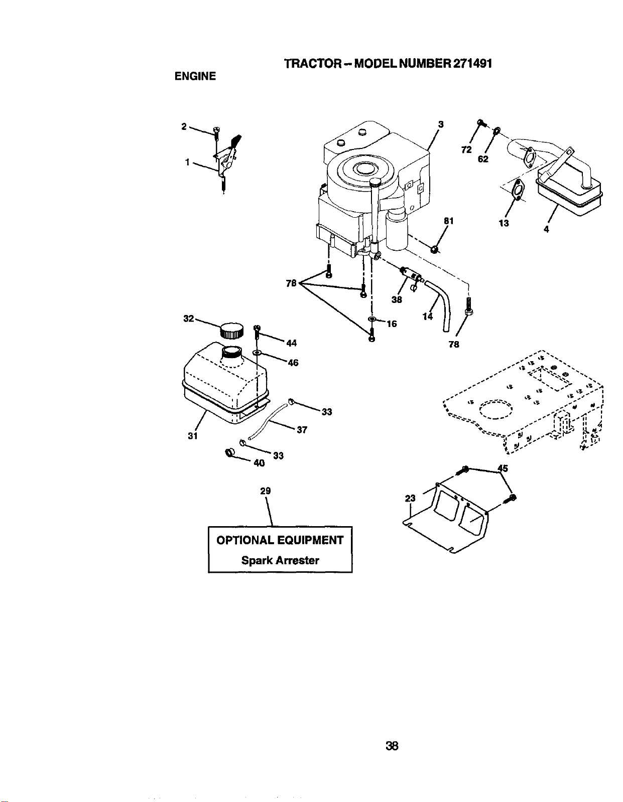
TRACTOR-- MODEL NUMBER 271491
ENGINE
31
33
3
81
78
29
I OPTIONAL EQUIPMENT
Spark Arrester
23
38
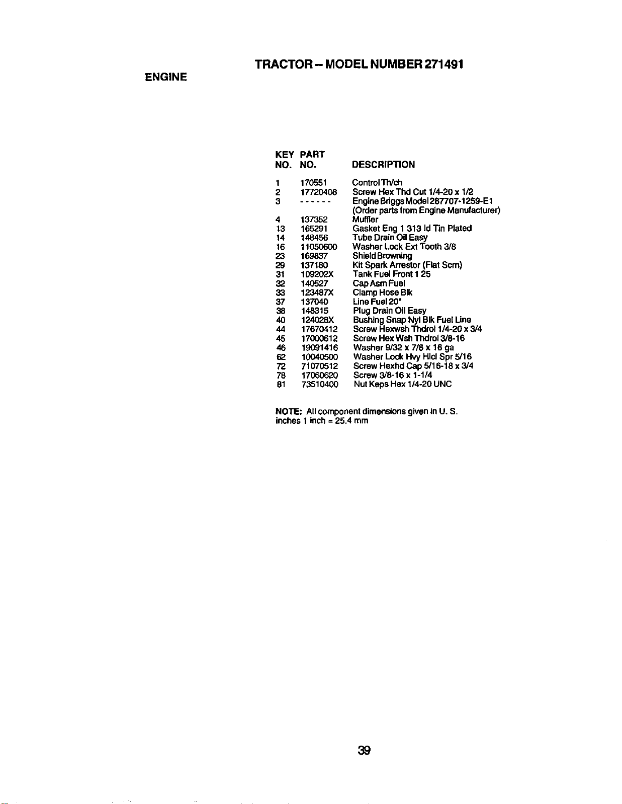
TRACTOR- MODEL NUMBER 271491
ENGINE
KEY PART
NO. NO. DESCRIPTION
1
2
3
170551
17720408
4 137352
13 165291
14 148456
16 11050600
23 169837
29 137180
31 109202)(
32 140527
33 123487x
37 137040
38 148315
40 124028)(
44 17670412
45 17000612
46 19091416
62 1004o5oo
72 71070512
78 17060620
81 73510400
ControlTWch
Screw Hex Thd Cut 1/4-20 x 1/2
EngineBdggsModel287707-1259-E1
(Orderparts fromEngineManufacturer)
Muffler
Gasket Eng 1 313 Id Tin Plated
Tube DrainOil Easy
Washer LockExtTooth 3/8
ShieldBrowning
KitSpark Arrestor(Flat Scm)
Tank Fuel Front I 25
Cap AsmFuel
ClampHose BIk
LineFuel 20"
Plug DrainOil Easy
BushingSnap Nyl BIkFuel Une
ScrewHexwsh Thdrol 1/4-20 x 3/4
ScrewHex WshThdrol3/8-16
Washer 9/32 x 718 x 16 ga
Washer LockHvy HlclSpr 5/16
Screw Hexhd Cap 5/16-18 x3/4
Screw 3/8-16 x 1-1/4
Nut Keps Hex 1/4-20 UNC
NOTE: All componentdimensionsgivenin U. S.
inches 1 inch = 25.4 mm
39
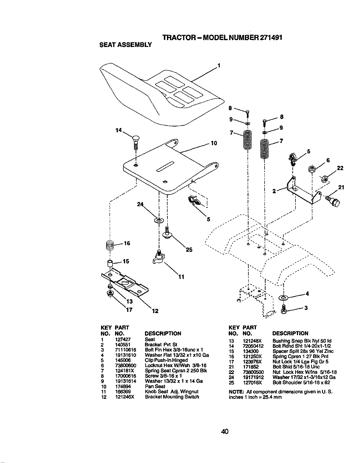
TRACTOR- MODELNUMBER271491
SEATASSEMBLY
KEY PART KEY PART
NO, NO. DESCRIPTION NO. NO,
1 127427 Seat 13 121248X
2 140551 Bracket Pvt St 14 72050412
3 71110616 BoltFin Hex 3/8-16unc x 1 15 134300
4 19131610 Washer Fiat 13/32 xl xl0 Ga 16 121250X
5 145006 Clip Push-In Hinged 17 123976X
6 73800600 Locknut Hex W/Wsh 3/8-16 21 171852
7 124181X SpringSeat Cprsn 2 250 BIk 22 73800500
8 17000616 Screw 3/8-16 x I 24 19171912
9 19131614 Washer 13/32 x I x 14 Ga 25 127018X
10 174894 Pan Seat
11 166369 Knob Seat Adj. Wingnut
12 121246)( Bracket MountingSwitch
DESCRIPTION
BushingSnap BIkNy150 Id
BoltRdhd Sht 1/4-20x1-1/2
Spacer Split28x 96 Yel Zinc
SpringCprsn 1 27 BIk Pnt
Nut Lock 1/4 Lge Fig Gr 5
Bolt Shld 5/16-18 Unc
Nut LockHex W/Ins 5/16-18
Washer 17/32 x1-3/16x 12 Ga
BoltShoulder5/16-18 x 62
NOTE: All componentdimensionsgiven inU, S.
inches 1 Inch = 25.4 mm
4O
TRACTOR- MODELNUMBER271491
DECALS
7
13
15
KEY PART
NO. NO.
1 177097
2 176396
3 171828
4 171829
5 145005
7 171830
8 156867
11 156439
12
KEY PART
DESCRIPTION NO. NO.
Decal LowerDash 12 181249
Decal Engine 13 146046
Decal Hood 15 136832
Decal Fender - - 138311
Decal BatteryDanger
Decal Steedng - - 182989
Decal, Oper sdl P/I. Gear - - 182990
Decal Fender Dnger
DESCRIPTION
Decal, Clutch/Brake Eng
Decal V-Bait Dr Sch tractor
Decal V-BeR sch
Decal HandleLit Height
Adjust(LiftHandle)
Owner's Manual,English
Owner's Manual,Spanish
WHEELS AND TIRES
4,10
11
KEY PART
NO. NO.
1 59192
2 65139
3 106222X
4 599O4
5 106732X427
6 278H
7 9040H
8 106108X427
9 124635X
10 7152J
11 104757X428
-- 144334
DESCRIPTION
Cap ValveTire
StemValve
Tire F Te 15 X 6 0 - 6 Service
Tube Front (Service Item Only)
Rim Asm6"frontWhite Service
FittingGrease (FrontWheel Only)
BearingFlange(frontWheel
Only)
Rim Asm8"rear White Service
Tire Rear
Tube Rear (Service Item Only)
Cap Axle BIk 1 50 X 1 00
Sealant, 11re( 10 oz. Tube)
NOTE: Allcomponent dimensionsgivenin U. S.
inches I inch= 25.4 mm
41
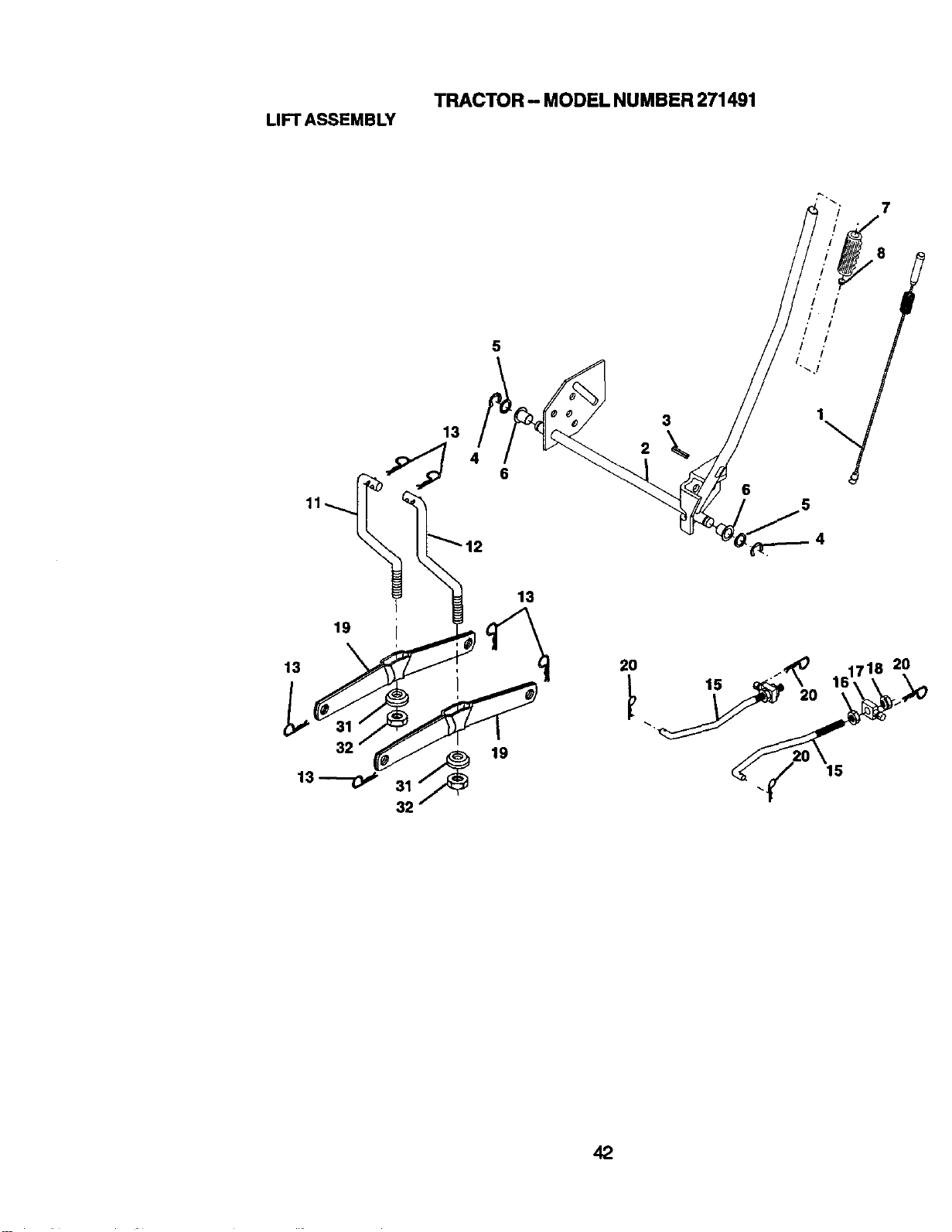
TRACTOR - MODEL NUMBER 271491
LIFT ASSEMBLY
7
8
5
13
4
6
3
2
6
19
13
13---o,*
32
13
19
15
42
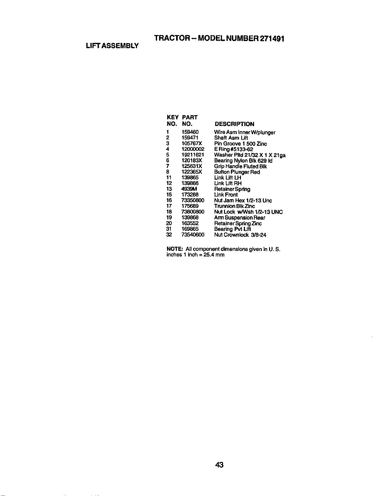
TRACTOR- MODELNUMBER271491
LIFTASSEMBLY
KEY PART
NO, NO, DESCRIPTION
1 159460 Wire Asm InnerW/plunger
2 159471 Shaft Asm Lift
3 105767X Pin Groove 1 500 Zinc
4 12000002 E Ring#5133.62
5 19211621 Washer Pltd21/32 X 1 X 21ga
6 120183X Bearing Nylon BIk629 Id
7 125631X Grip Handle FlutedBIk
8 122365X ButtonPlungerRed
11 139865 Link Uft LH
12 139866 Link Lift RH
13 4939M RetainerSpring
15 173288 Link Front
16 73350800 Nut Jam Hex 1/2-13 Unc
17 175689 TrunnionBIkZinc
18 73800800 Nut Lock w/Wsh 1/2-13 UNC
19 139868 ArmSuspensionRear
20 163552 Retainer SpdngZinc
31 169865 Beadng Pvt Lift
32 73540600 Nut Crownlock 3/8-24
NOTE: All componentdimensions givenin U. S.
inches 1 inch = 25.4 mm
43
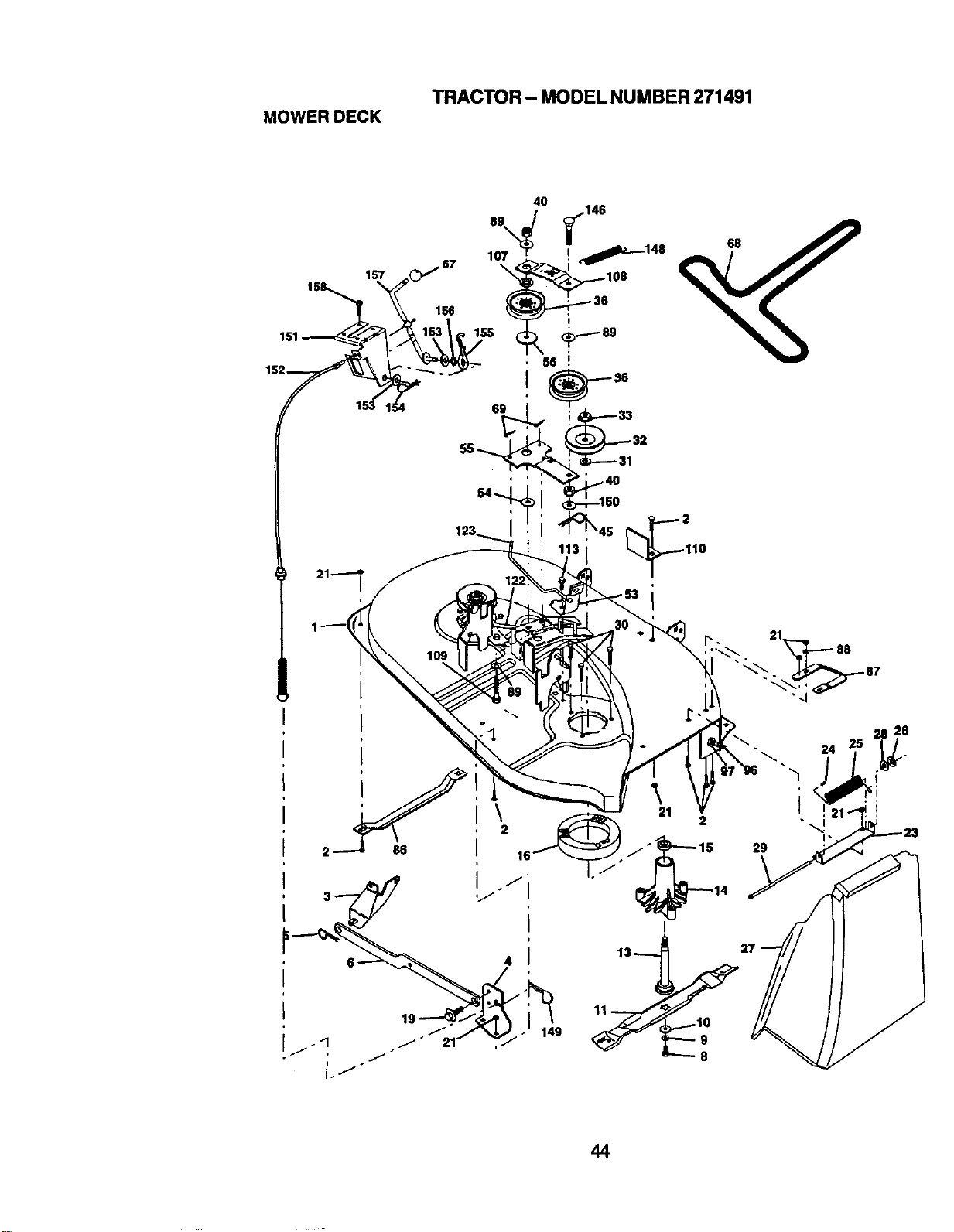
TRACTOR- MODELNUMBER271491
MOWERDECK
2
2
11
2
24
I
29
28 26
I
44
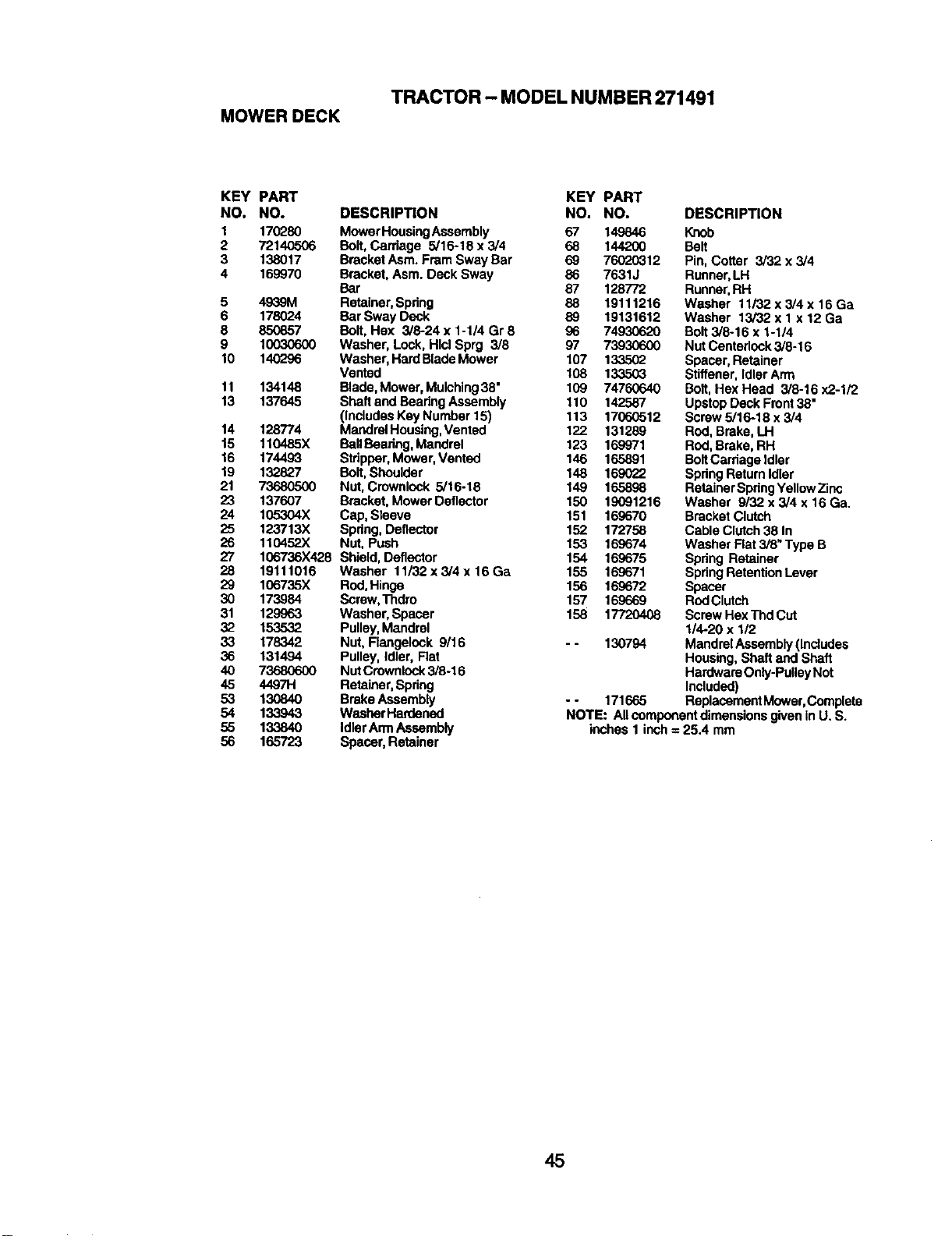
TRACTOR - MODEL NUMBER 271491
MOWER DECK
KEY PART
NO. NO.
1 170280
2 72140506
3 138017
4 169970
5 4939M
6 178(_4
8 850857
9 10O3O6O0
10 140296
11 134148
13 137645
14 128774
15 110485X
16 174493
19 132827
21 73680500
23 137607
24 105304X
25 123713X
26 110452X
27 106736X428
28 19111016
29 106735X
30 173984
31 129963
32 153532
33 178342
36 131494
4O 73680600
45 4497H
53 13O84O
54 133943
55 13384O
56 165723
KEY PART
DESCRIPTION NO. NO.
MowerHousingAssembly 67 149846
Bolt,Carriage 5/16-18 x3/4 68 144200
BracketAsm. Fram Sway Bar 69 76020312
Bracket,Asm. Deck Sway 86 7631J
Bar 87 128772
Retainer,Spdng 88 19111216
Bor Sway Deck 89 19131612
Bolt, Hax 3/8-24 x 1-1/4 Gr 8 96 74930620
Washer, Lock, Hid Sprg 3/8 97 73930600
Washer, Hard BladeMower 107 133502
Vented 108 133503
Blade,Mower, Mulching38" 109 74760640
Shaft andBearingAssembly 110 142587
(IncludesKey Number 15) 113 17060512
MandrelHousing,Vented 122 131289
BallBearing,Mandrel 123 169971
Stripper,Mower,Vented 146 165891
Bolt, Shoulder 148 169022
Nut,Crownlock 5/16-18 149 165898
Bracket,Mower Deflector 150 19091216
Cap, Sleeve 151 169670
Spring,Deflector 152 172758
Nut, Push 153 169674
Shield, Deflector 154 169675
Washer 11i32x3/4x16Ga 155 169671
Red, Hinge 156 169672
Screw,Thdro 157 169669
Washer, Spacer 158 17720408
Pulley,Mandrel
Nut, Flangelock 9/16 - - 130794
Pulley, Idler, Flat
NUtCrownlock3/6-16
Retainer,Spring
Brake Assembly - - 171665
WashorHan_ened
IdlerArmAssembly
Spacer, Retainer
DESCRIPTION
Knob
Belt
Pin, Cotter 3/32 x 3/4
Runner,LH
Runner,RH
Washer 11/32 x 3/4 x 16 Ga
Washer 13/32 x 1 x 12 Ga
Bolt3/8o16x 1-1/4
Nut Centeriock3/8-16
Spacer, Retainer
Stiffener,Idler Arm
Bolt,Hex Head 3/8-16 x2-1/2
UpstopDeck Front38"
Screw 5/16-18 x 3/4
Rod, Brake,LH
Rod, Brake,RH
BoltCarriageidler
SpdngRetum Idler
RetainerSpringYellowZinc
Washer 9/32 x 3/4 x 16 Ga.
Bracket Clutch
Cable Clutch38 In
Washer Flat 3/8" Type B
Spring Retainer
SpringRetentionLever
Spacer
RodClutch
Screw HexThdCUt
1/4-20 x 1/2
MandrelAssembly (Includes
Housing, Shaft and Shaft
HardwareOnly-PulleyNot
Included)
ReplacementMower,Complete
NOTE: All componentdimensionsgivenin U. S.
inches 1 inch = 25.4 mm
45
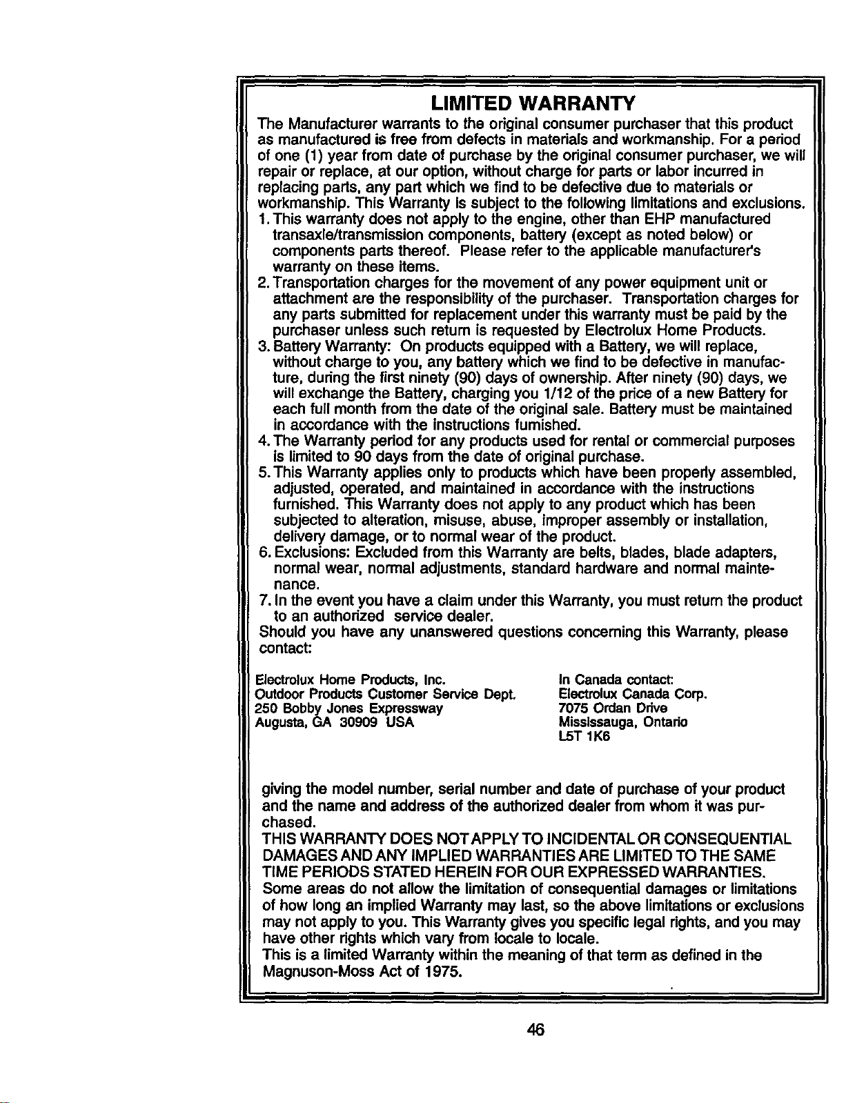
LIMITED WARRANTY
The Manufacturer warrants to the original consumer purchaser that this product
as manufactured is free from defects in materials and workmanship. For a period
of one (I) year from date of purchase by the original consumer purchaser, we will
repair or replace, at our option, without charge for parts or labor incurred in
replacing parts, any part which we find to be defective due to materials or
workmanship. This Warranty Is subject to the following limitationsand exclusions.
1.This warranty does not apply to the engine, other than EHP manufactured
transaxle/transmission components, battery (except as noted below) or
components pads thereof. Please refer to the applicable manufacturer's
warranty on these items.
2. Transportation charges for the movement of any power equipment unit or
attachment are the responsibility of the purchaser. Transportation charges for
any parts submitted for replacement under this warranty must be paid by the
purchaser unless such return is requested by Electrolux Home Products.
3. Battery Warranty: On products equipped with a Battery, we will replace,
without charge to you, any battery which we find to be defective in manufac-
ture, during the first ninety (90) days of ownership. After ninety (90) days, we
willexchange the Battery, charging you 1/12 of the price of a new Battery for
each full month from the date of the original sale. Battery must be maintained
in accordance with the instructionsfumished.
4. The Warranty pedod for any products used for rental or commercial purposes
is limited to 90 days from the date of originalpurchase.
5.This Warranty applies only to products which have been properly assembled,
adjusted, operated, and maintained in accordance with the instructions
furnished. This Warranty does not apply to any productwhich has been
subjected to alteration, misuse, abuse, improper assembly or installation,
delivery damage, or to normal wear of the product.
6. Exclusions: Excluded from this Warranty are belts, blades, blade adapters,
normal wear, normal adjustments, standard hardware and normal mainte-
nance.
7. In the event you have a claim under this Warranty, you must return the product
to an authorized service dealer.
Should you have any unanswered questions concerning this Warranty, please
contact:
Electmlux Home Products, Inc.
Outdoor Products Customer Service Dept.
250 Bobby Jones Expressway
Augusta, GA 30909 USA
In Canada contact:
Electrolux Canada Corp,
7075 Ordan Ddve
Mississauga, Ontado
L5T 1K6
giving the model number, serial number and date of purchase of your product
and the name and address of the authorized dealer from whom it was pur-
chased.
THIS WARRANTY DOES NOTAPPLY TO INCIDENTAL OR CONSEQUENTIAL
DAMAGES AND ANY IMPLIED WARRANTIES ARE LIMITED TO THE SAME
TIME PERIODS STATED HEREIN FOR OUR EXPRESSED WARRANTIES.
Some areas do not allow the limitation of consequential damages or limitations
of how long an implied Warranty may last, so the above limitations or exclusions
may not apply to you. This Warranty gives you specific legal rights, and you may
have other dghts which vary from locale to locale.
This is a limited Warranty within the meaning of that term as defined in the
Magnuson-Moss Act of 1975.
46

SUGGESTED GUIDE FOR SIGHTING SLOPES FOR SAFE OPERATION
1. Fold this page along dotted line Indicated above.
2. Hold page before you so that Its left edge Is vertically parallel to s tree
trunk or other upright structure.
3. Sight across the fold In the direction of hill slope you want to measure.
4. Compare the angle of the fold with the slope of the hill.

Poulan