
IMPORTANT MANUAL Do Not Throw Away
|
TM
OWNER'S MANUAL
MODEL:
PR16H42STA
LAWN TRACTOR
WARNING:
Read this Owner's Manual and follow
all Warnings and Safety Instructions.
Failure to do so can result in serious
injury.
ALWAYS WEAR EYE PROTECTION DURING OPERATION
279840 PR16H42STA 173298 Rev. 1 2.10.00 TR/MH
Printed in U.S.A.
SAFETY RULES
& Safe Operation Practices for Ride-On Mowers &
IMPORTANT: THIS CUTTING MACHINE IS CAPABLE OF AMPUTATING HANDS AND FEET AND THROWING OBJECTS.
FAILURE TO OBSERVE THE FOLLOWING SAFETY INSTRUCTIONS COULD RESULT IN SERIOUS INJURY OR DEATH.
I, GENERALOPERATION
•Read, understand, and follow all instructions in the
manual and on the machine before starting.
• Only allowresponsible adults, who are familiar withthe
instructions,to operate the machine.
•Clear thearea ofobjectssuch as recks, toys, wire,etc.,
whichcould be picked up and thrown by the blade.
•Besure thearea isclear ofother people before mowing.
Stop machine ifanyone enters the area.
•Never carry passengers.
• Do not mow in reverse unless absolutely necessary.
Always look down and behind before and while backing.
• Be aware of the mower discharge direction and do not
point it at anyone. Do not operate the roower without
either the entire grass catcher or the guard in place.
• Slow down before tuming.
• Never leave a running machine unattended. Alwaysturn
off blades, set parking brake, stop engine, and remove
keys before dismounting.
• Turn off blades when not mowing.
• Stop engine before removing grass catcher or unclog-
ging chute.
• Mow only in daylight or good artificial light.
• Do not operate the machine while under the influence of
alcohol or drugs.
• Watch for traffic when operating near or crossing road-
ways.
• Use extra care when loading or unloading the machine
into a trailer or truck.
• Data indicates that operators, age 60 years and above,
are involved in a large percentage of riding mower-
related injuries. These operators should evaluate their
ability to operate the riding mower safely enough to
protect themselves and others from serious injury.
I1. SLOPE OPERATION
Slopesare a majorfactor relatedto loss-of-controland tipover
accidents,whichcan resultinsevere injuryor death. Allslopes
requireextracaution.Ifyoucannotbackuptheslopeorifyoufeel
uneasyon it,do notmowit.
DO:
•MOWup and down slopes, not across.
•Remove obstacles such as rocks, tree limbs, etc.
•Watch for holes, ruts,or bumps. Uneven terrain could
overturnthe machine. Ta/I grass can hide obstacles.
•Use slowspeed. Choose a low gear so that you willnot
have tostop or shift while on the slope.
•Followthe manufacturer's recommendations for wheel
weights orcounterweights to improve stability.
•Use extra care with grass catchers or other attach-
ments. These can change the stability of the machine.
Keepallmovementonthe slopesslowand gradual. Donot
makesuddenchangesin speed or direction.
Avoidstartingor stoppingon a slope. If tires losetraction,
disengagethebladesand proceedslowlystraightdownthe
slope.
DO NOT:
•Do not turn on slopes unless necessary, and then, turn
slowly and gradually downhill, ifpossible,
•Do not mow near drop-offs, ditches, or embankments.
The mower couldsuddenly turnover ifawheeiis overthe
edge of a cliff or ditch, or if an edge caves in.
•Donotmowonwetgrass. Reduced tractioncouldcause
sliding.
•Donottrytostabilizethemachinebyputtingyourfoot
onthe ground.
•Do not use grass catcher on steep slopes.
Ul. CHILDREN
Tragic accidents can occur ifthe operator isnot alert tothe
presence of children. Children are often attracted to the
machine and the mowing activity. Never assume that
children will remain where you last saw them.
•Keep children out of the mowing area and under the
watchful care ofanother responsible adult,
•Be alert and turn machine off if children enter the area.
•Before and when backing, look behind and down for
small chUdren.
•Never carry children. They may fall offand be sedously
injured or interfere with safe machine operation.
•Never allow children to operate the machine.
•Use extra care when approaching blindcomers, shrubs,
trees, or other objects that may obscure vision.
IV. SERVICE
•Use extra care in handling gasoline and other fuels.
They are flammable and vapors are explosive.
-Use only an approved container.
-Never remove gas cap or add fuel with the engine
running. AIIowenginetocoolbeforerefueling. Donot
smoke.
-Never refuel the machine indoors.
-Never storethe machine orfuelcontainer insidewhere
there is an open flame, such as a water heater.
• Never run a machine inside a closed area.
• Keep nuts and bolts, especially blade attachment bolts,
tight and keep equipment in good condition.
• Never tamper with safety devices. Check their preper
operation regularly.
•Keep machine free of grass, leaves, or other debris
build-up. Clean oil or fuel spillage. Allow machine tocool
before storing.
• Stop and inspect the equipment if you strike an object.
Repair, ifnecessary, before restarting.
•Never make adjustments or repairs with the engine
running.
• Grass catcher components are subjectto wear, dam-
age, and deterioration,whichcould exposemovingparts
orallowobjectstobethrown. Frequently checkcompo-
nents and replace with manufacturer's recommended
parts, when necessary.
•Mower blades are sharp and can cut. Wrap theblade(s)
or wear gloves, and use extra caution when servicing
them.
•Check brake operation frequently. Adjustand service
as required.
2
SAFETY RULES
Safe Operation Practices for Ride-On Mowers &
Be sure the area isclearof other people before mowing, Stop
machine if anyone enters the area,
Never carry passengers or children even with the blades off.
Do not mow in reverse unless absolutely necessary. Always
look down and behind before and while backing.
Never carry children. They may fall off and be seriously
injured or interfere with safe machine operation.
Keep children out of the mowing area and under the watchful
care of another responsible adult,
Be alert and turn machine oft if children enter the area.
Before and when backing, look behind and down for small
children.
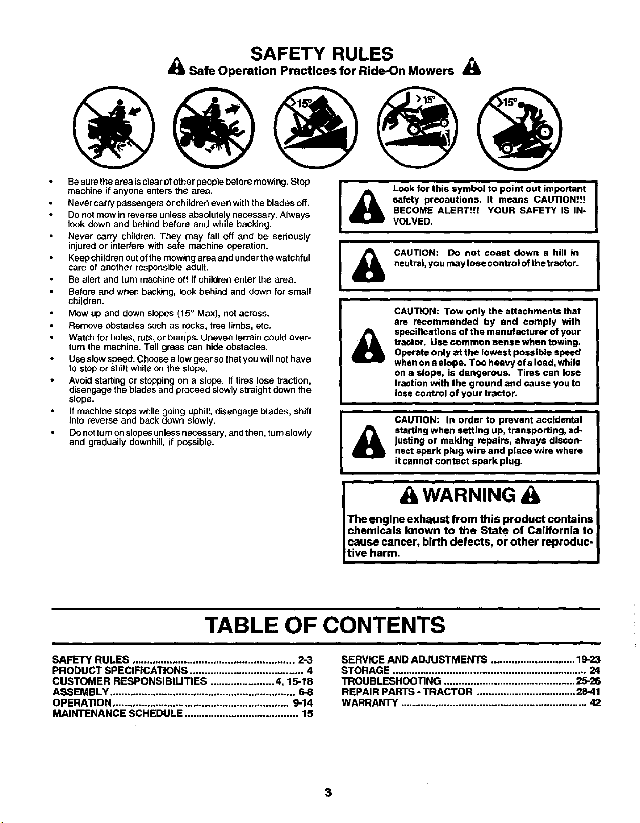
Mow up and down slopes (15°Max), not across.
Remove obstacles such as rocks, tree limbs, etc,
Watch for holes, ruts, or bumps. Uneven terrain could over-
turn the machine. Tall grass can hide obstacles.
Use slow speed. Choose a low gear so that you willnot have
to stop or shift while on the slope.
Avoid starting or stopping on a slope. If tires lose traction,
disengage the blades and proceed slowly straight down the
slope.
If machine stops while going uphill, disengage blades, shift
into reverse and back down slowly.
Do nottum onslopes unless necessary, and then, turn slowly
and gradually downhill, if possible.
I
I
Lock for this symbol to point out important
safety precautions. It means CAUTION!I!
BECOME ALERT!!! YOUR SAFETY IS IN-
VOLVED.
CAUTION: Do not coast down a hill in
neutral, you may lose control ofthe tractor.
CAUTION: Tow only the attachments that
are recommended by and comply with
specifications of the manufacturer of your
tractor. Use common sense when towing.
Operate only at the lowest possible speed
when on a slope. Too heavy of a load, while
on a slope, is dangerous, Tires can lose
traction with the ground and cause you to
lose control of your tractor.
&CAUTION: In order to prevent accidental
starting when setting up, transporting, ad-
justing or making repairs, always discon-
nect spark plug wire and place wire where
it cannot contact spark plug.
I
I
AWARNING
The engine exhaust from this product.contains
chemicals known to the State of Califorma to
cause cancer, birth defects, or other reproduc-
tive harm.
TABLE OF CONTENTS
SAFETY RULES ........ 2-3
,,..,. ,.,.., .,o... ,.H°. ,,==,, ...,,= ,..,.. ,*...,
PRODUCT SPECIFICATIONS ....................................... 4
CUSTOMER RESPONSIBILITIES ...................... 4, 15-18
ASSEMBLY ................................................................ 6-8
OPERATION ............................................................. 9-14
MAINTENANCE SCHEDULE ....................................... 15
SERVICE AND ADJUSTMENTS ............................. 19-23
STORAGE ................................................................... 24
TROUBLESHOOTING ............................................. 25-26
REPAIR PARTS -TRACTOR .................................. 28-41
WARRANTY . . 42
,,,.,o.,.,.=,,,.,,==,,..,h......=o°...° ..,,.,.,H,,, .,,,.,,,,
3
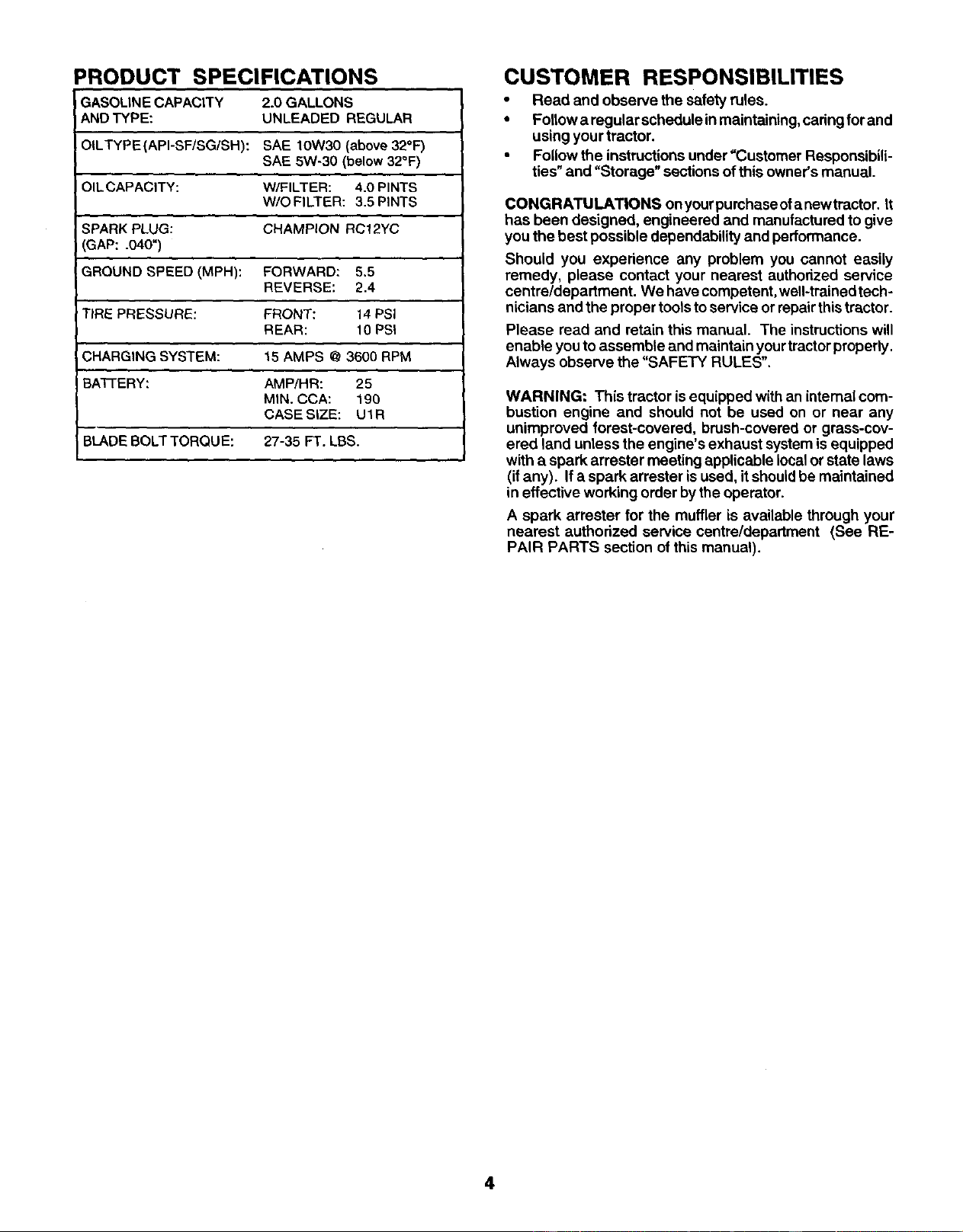
PRODUCT SPECIFICATIONS
GASOLINE CAPACITY
AND TYPE:
OILTYPE (API-SF/SG/SH):
2.0 GALLONS
UNLEADED REGULAR
SAE 10W30 (above 32°F)
SAE 5W-30 (below 32°F)
OIL CAPACITY: W/FILTER: 4.0 PINTS
W/OFILTER: 3,5 PINTS
SPARK PLUG: CHAMPION RC12YC
GAP: .040")
GROUND SPEED (MPH): FORWARD: 5.5
REVERSE: 2.4
TIRE PRESSURE: FRONT: 14 PSi
REAR: 10 PSi
CHARGING SYSTEM: 15 AMPS @ 3600 RPM
BA'I-FERY: AMP/HR: 25
MIN. CCA: 190
CASE SIZE: U1R
BLADE BOLT TORQUE: 27-35 FT. LBS.
CUSTOMER RESPONSIBILITIES
•Read and observe the safety rules.
•Follow a regular schedule inmaintaining, caring forand
using your tractor.
•Follow the instructionsunder =Customer Responsibili-
ties" and "Storage" sections ofthis owner's manual.
CONGRATULATIONS onyourpurchaseofanewtractor. It
has been designed, engineered and manufactured to give
you the best possible dependability and performance.
Should you experience any problem you cannot easily
remedy, please contact your nearest authorized service
centre/department. We have competent, well-trained tech-
nicians and the proper toolstoservice or repairthis tractor.
Please read and retain this manual. The instructions will
enable you to assemble and maintain yourtractorproperly.
Always observe the "SAFETY RULES".
WARNING: This tractor isequipped with an internal com-
bustion engine and should not be used on or near any
unimproved forest-covered, brush-covered or grass-cov-
ered land unless the engine's exhaust system is equipped
with a spark arrester meeting applicable localor state laws
(ifany). If a spark arrester isused, itshouldbe maintained
in effective working order bythe operator.
A spark arrester for the muffler is available through your
nearest authorized service centre/department (See RE-
PAIR PARTS section of this manual).
4
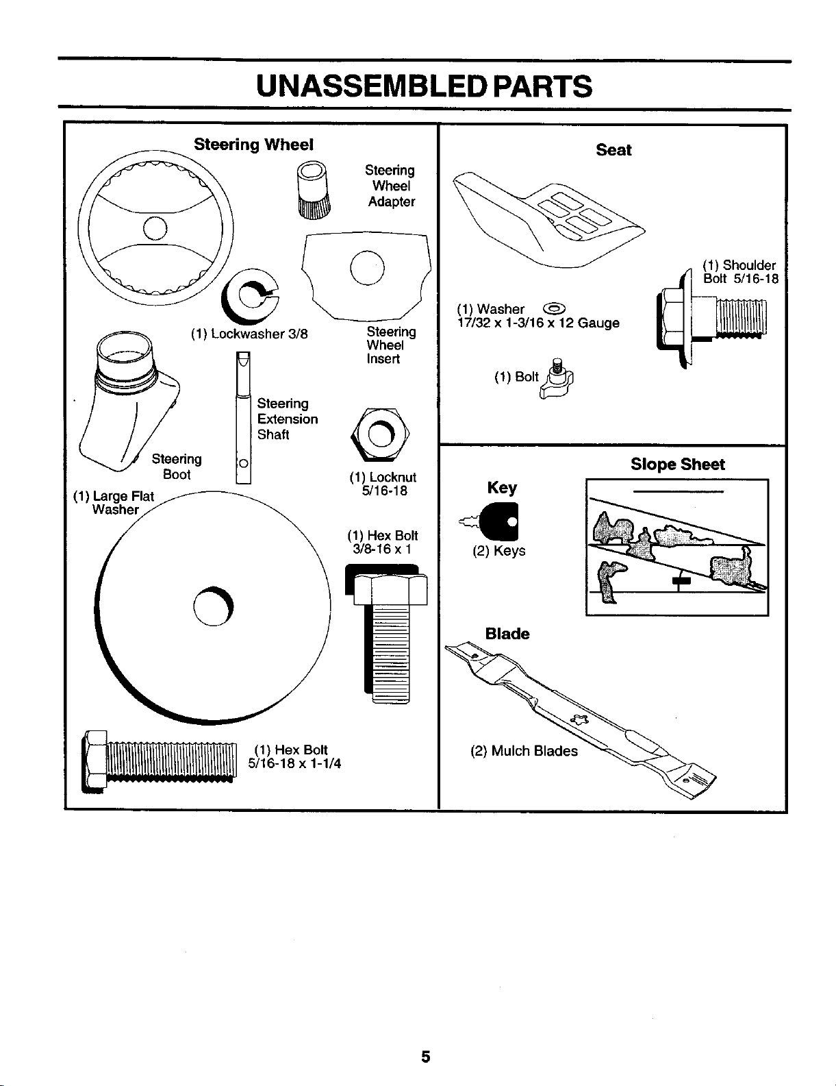
UNASSEMBLED PARTS
Steering Wheel
Steering
Boot
(1)Large Flat
Washer
(1) Lockwasher 3/8
t teedng
E_ension
Shaft
(1)HexBolt
5/16-18 x1-1/4
Steering
Wheel
Adapter
Steering
Wheel
Insert
(1) Locknut
5/16-18
(1) Hex Bolt
3/8-16 x 1
Seat
(1) Washer
17/32 x1-3/16 x12 Gauge
(1) Shoulder
Bolt 5/16-18
(1) Bolt_
Key
(2) Keys
Slope Sheet
Blade
5
ASSEMBLY
Your newtractor has been assembled atthefactorywith exception ofthose parts leftunassembled forshipping purposes. To
ensure safe and proper operation of yourtractor all parts and hardware you assemble mustbe tightened securely. Use the
correct tools as necessary to insure propertightness.
TOOLS REQUIRED FOR ASSEMBLY
A socket wrench set will make assembly easier. Standard
wrench sizes are listed.
(1) 9/16" wrench Pliers
(2) 7/16" wrenches Tirepressuregauge
(2) 1/2"wrenches Utility knife
When rightor lefthand ismentioned inthismanual, itmeans
when you are in the operating position (seated behind the
steeringwheel).
TO REMOVE TRACTOR FROM CARTON
UNPACK CARTON
•Remove all accessible loose pads and parts cartons
from carton.
•Cut, from top to bottom, along lines on all fourcorners
of carton, and lay panels flat.
•Check for any additional loose parts or cartons and
remove.
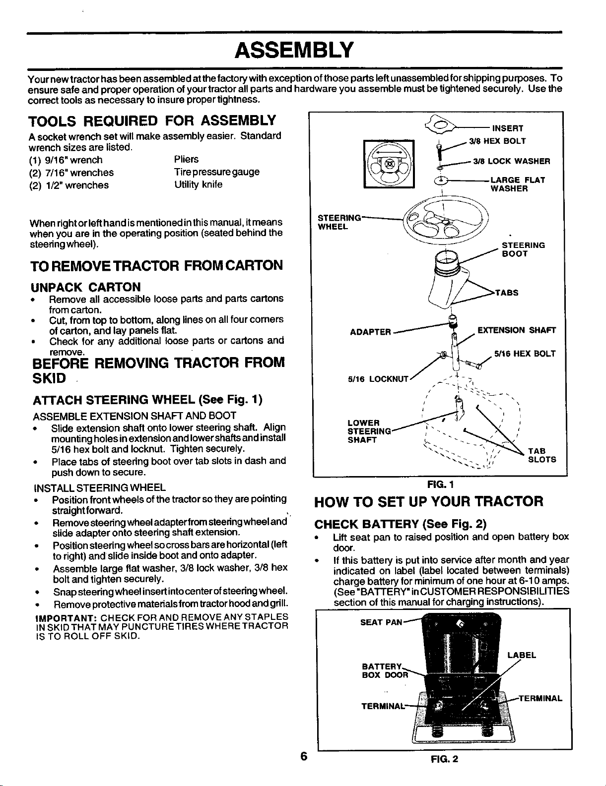
BEFORE REMOVING TRACTOR FROM
SKID
ATTACH STEERING WHEEL (See Fig. 1)
ASSEMBLE EXTENSION SHAFT AND BOOT
• Slide extension shaft onto lower steering shaft. Align
mounting holes inextension and lowershaftsand install
5/16 hex bolt and Iocknut. Tighten securely.
•Place tabs of steering boot over tab slots in dash and
push down to secure.
INSTALL STEERING WHEEL
•Position front wheels ofthe tractorso theyare pointing
straightforward.
• Remove steedngwheel adapterfrom steeringwheeland
slide adapter onto steering shaftextension.
•Positionsteering wheel socrossbarsare horizontal(left
to right) and slide inside boot and onto adapter.
•Assemble large flat washer, 3/8 lock washer, 3/8 hex
bolt and tighten securely.
•Snap steering wheel insertintocenter ofsteeringwheel.
•Remove protective materials fromtractorhoodand gdll.
IMPORTANT: CHECK FOR AND REMOVE ANY STAPLES
IN SKID THAT MAY PUNCTURE TIRES WHERE TRACTOR
IS TO ROLL OFF SKID.
_='--_ INSERT
3/8 LOCK WASHER
(_-_ LARGE FLAT
WASHER
STEERING_
WHEEL STEERING
_BOOT
/_....._TABS
ADAPTER _EXTENSION SHAFT
7
I
BOLT
5,,SLOCKNOT
LOWER _ _','
STEERING_ ! _ t,_ ,_.
"-." -. bJ SLOTS
FIG. 1
HOW TO SET UP YOUR TRACTOR
CHECK BA'I-FERY (See Fig. 2)
•Lift seat pan to raised position and open battery box
door.
•If this battery is put into service after month and year
indicated on label (label located between terminals)
charge battery for minimum ofone hour at 6-10 amps.
(See "BATTERY" inCUSTOMER RESPONSIBILITIES
section of this manual for charging instructions).
SEAT
BOX
LABEL
6FIG. 2
ASSEMBLY
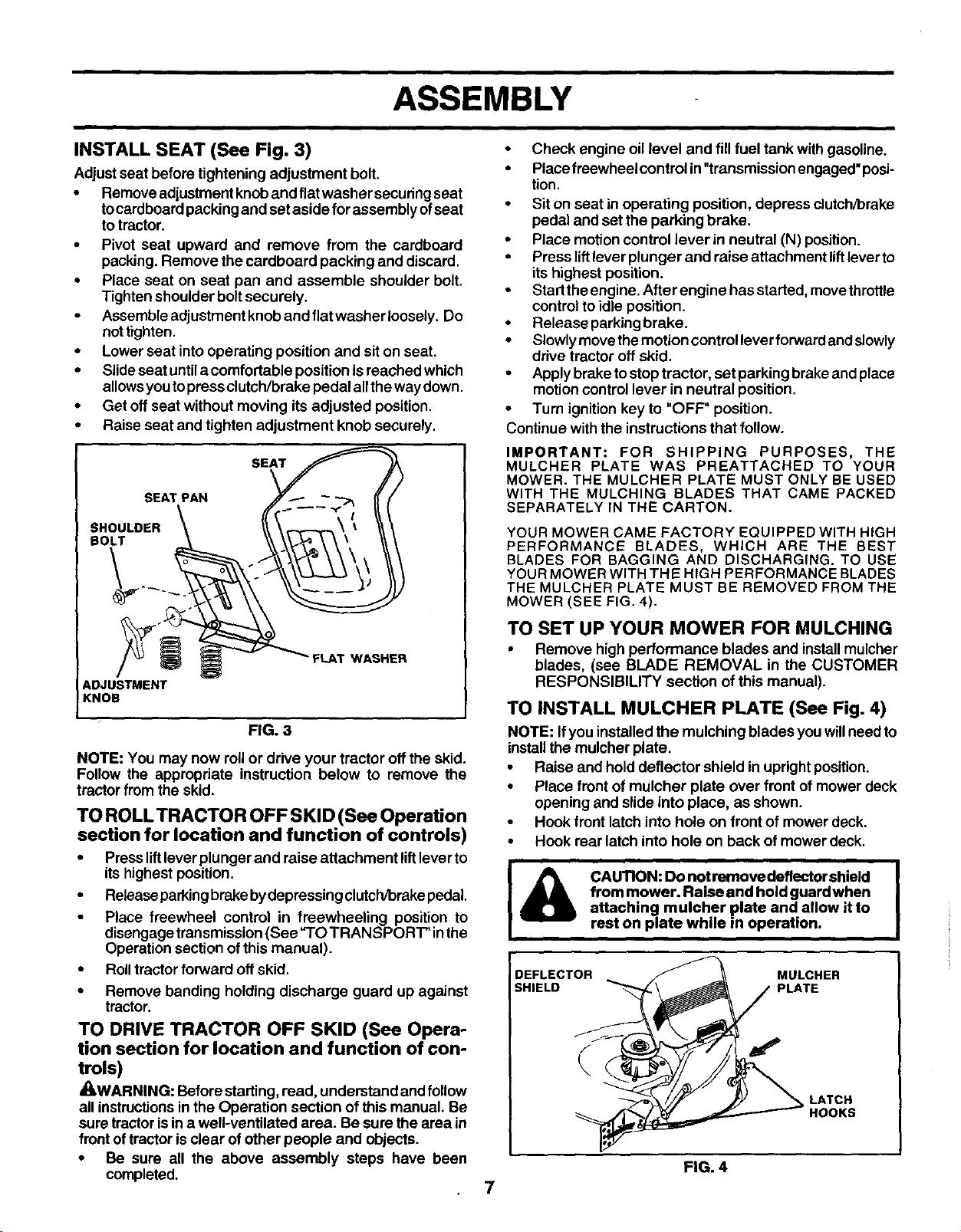
INSTALL SEAT (See Fig. 3)
Adjust seat before tightening adjustment bolt.
• Remove adjustment knoband flatwasher securingseat
tocardboard packingand set aside for assembly ofseat
totractor.
•Pivot seat upward and remove from the cardboard
packing. Remove the cardboard packing and discard,
•Place seat on seat pan and assemble shoulder bolt.
Tighten shoulder boltsecurely.
•Assemble adjustment knob and flatwasher loosely. Do
not tighten.
•Lower seat intooperating position and siton seat.
•Slide seat untila comfortable position isreached which
allowsyou topressclutch/brake pedal allthe waydown,
•Get off seat without moving its adjusted position,
•Raise seat and tighten adjustment knob securely.
SEAT
SEAT PAN
SHOULDER
DOLT
ADJUSTMENT
KNOB
WASHER
FIG. 3
NOTE: You may now roll or drive your tractor offthe skid.
Follow the appropriate instruction below to remove the
tractorfrom the skid.
TO ROLL TRACTOR OFF SKID (See Operation
section for location and function of controls)
• Press liftlever plunger and raise attachment liftlever to
its highest position.
• Releaseparkingbrakebydepressingclutch/brakepedal,
•Place freewheel control in freewheeling position to
disengagetransmission (See "TO TRANSPORT" inthe
Operation sectionof this manual).
•Rolltractor forward offskid.
• Remove banding holding discharge guard up against
tractor.
TO DRIVE TRACTOR OFF SKID (See Opera-
tion section for location and function of con-
trols)
_WARNING: Before starting,read, understand andfollow
all instructionsin the Operation section of this manual. Be
sure tractorisin a well-ventilated area. Be sure the area in
frontoftractor is clear of other people and objects.
•Be sure all the above assembly steps have been
completed.
•Check engine oillevel and fillfuel tank with gasoline.
• Placefreewheel control in "transmissionengaged"posi-
tion.
•Siton seat in operating position, depress clutch/brake
pedal and set the parking brake.
•Place motion control lever in neutral (N) position.
Press liftlever plunger and raise attachment liftleverto
itshighest position.
• Starttheengine.Afterenginehasstarted, movethrottle
controlto idle position.
• Release parkingbrake.
•Slowlymovethemotion controlleverforward and slowly
drive tractor off skid.
•Apply brake tostop tractor, set parking brake and place
motion control lever in neutral position.
•Turn ignition key to "OFF" position.
Continue with the instructions that follow.
IMPORTANT: FOR SHIPPING PURPOSES, THE
MULCHER PLATE WAS PREATTACHED TO YOUR
MOWER. THE MULCHER PLATE MUST ONLY BE USED
WITH THE MULCHING BLADES THAT CAME PACKED
SEPARATELY IN THE CARTON.
YOUR MOWER CAME FACTORY EQUIPPED WITH HIGH
PERFORMANCE BLADES, WHICH ARE THE BEST
BLADES FOR BAGGING AND DISCHARGING. TO USE
YOUR MOWER WITH THE HIGH PERFORMANCE BLADES
THE MULCHER PLATE MUST BE REMOVED FROM THE
MOWER (SEE FIG. 4).
TO SET UP YOUR MOWER FOR MULCHING
•Remove high performance blades and installmulcher
blades, (see BLADE REMOVAL in the CUSTOMER
RESPONSIBILITY section of this manual).
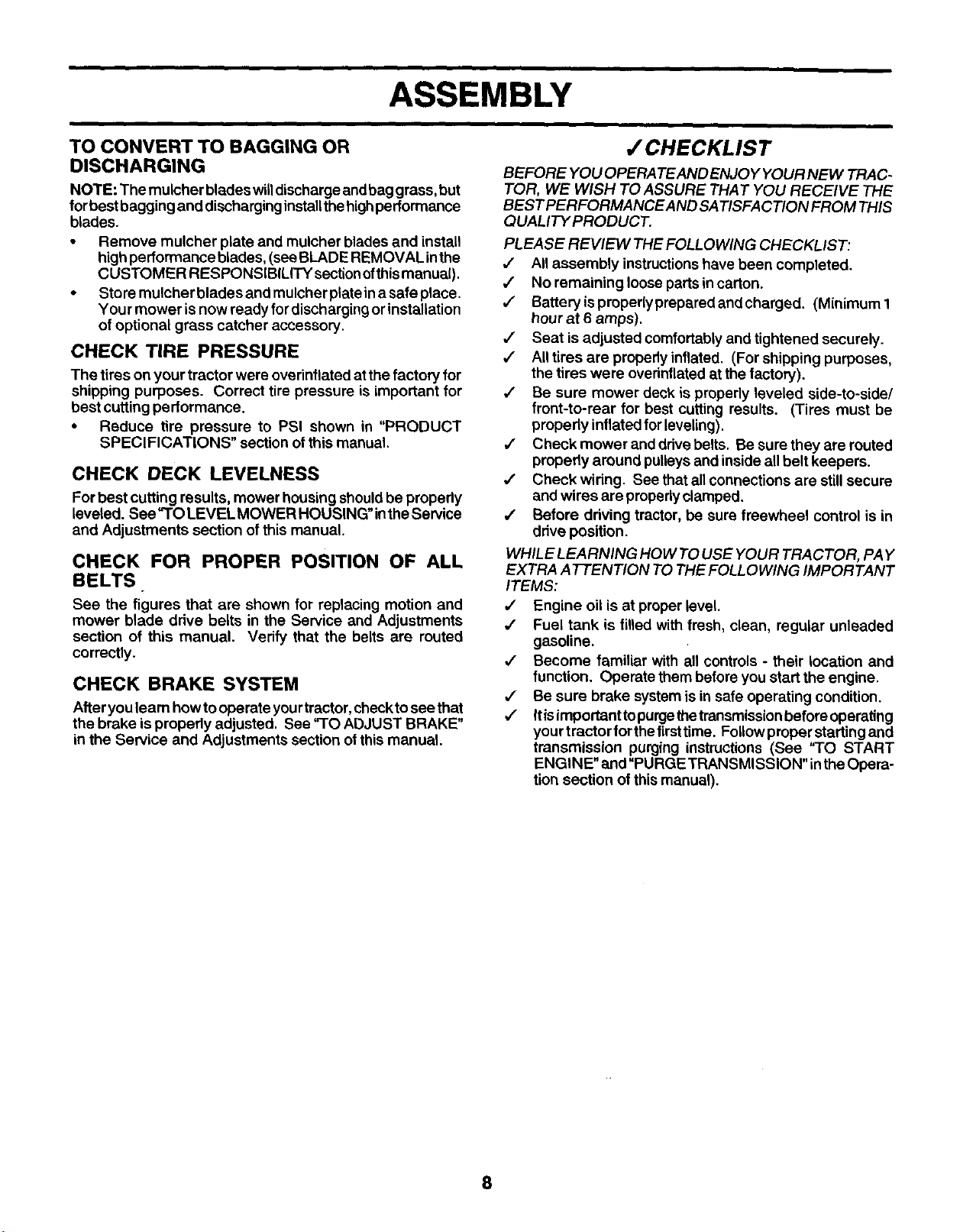
TO INSTALL MULCHER PLATE (See Fig. 4)
NOTE: Ifyou installedthe mulching blades you willneed to
installthe mulcher plate.
•Raise and hold deflector shield in upright position.
•Place frontof mulcher plate over front of mower deck
opening and slide into place, as shown.
•Hook front latch into hole on front of mower deck.
•Hook rear latch into hole on back of mower deck.
I& CAUTION: Do not remove deflector shield
from mower. Raise and hold guard when
attaching mulcher plate and allow it to
rest on plate while in operation.
DEFLECTOR MULCHER
SHIELD PLATE
LATCH
HOOKS
FIG. 4
7
ASSEMBLY
•/ CHECKLIS T
TO CONVERT TO BAGGING OR
DISCHARGING
NOTE: The mulcher blades willdischargeand bag grass, but
for best bagging and discharging install the high performance
blades.
•Remove mulcher plate and mulcher blades and install
high performance blades, (seeBLADE REMOVAL inthe
CUSTOMER RESPONSIBILITY section ofthis manual).
• Store mulcher blades and mulcher plate in a safe place.
Your mower is now ready for discharging or installation
of optional grass catcher accessory.
CHECK TIRE PRESSURE
The tires on your tractor were overinflated at the factory for
shipping purposes. Correct tire pressure is important for
best cutting performance.
• Reduce tire pressure to PSI shown in "PRODUCT
SPECIFICATIONS" section of this manual.
CHECK DECK LEVELNESS
For best cutting results, mower housing shouldbe propedy
leveled. See "TO LEVEL MOWER HOUSING" inthe Service
and Adjustments section ofthis manual.
CHECK FOR PROPER POSITION OF ALL
BELTS
See the figures that are shown for replacing motion and
mower blade drive belts in the Service and Adjustments
section of this manual. Verify that the belts are routed
correctly.
CHECK BRAKE SYSTEM
After you learn howto operate you rtractor, checktosee that
the brake is properly adjusted. See "TO ADJUST BRAKE"
in the Service and Adjustments section ofthis manual.
BEFORE YOU OPERA TEAND ENJO YYOUR NEW TRAC-
TOR, WE WISH TO ASSURE THAT YOU RECEIVE THE
BEST PERFORMANCE AND SATISFACTION FROM THIS
QUALITYPRODUCT.
PLEASE REVIEW THE FOLLOWING CHECKLIST:
•/All assembly instructionshave been completed.
,/ No remaining looseparts in carton.
J Batteryispropedypreparedandcharged. (Minimum1
hour at 6 amps).
,I Seat is adjusted comfortably and tightened securely.
,/ All tires are propedy inflated. (For shipping purposes,
the tires were overinflated at the factory).
J Be sure mower deck is properly leveled side-to-side/
front-to-rear for best cutting results. (Tires must be
propedy inflated forleveling).
,I Check mower and drive belts. Be sure they are routed
propedy around pulleysand inside all belt keepers.
,/ Check wiring. See that all connections are stillsecure
and wires are propedyclamped.
4" Before driving tractor, be sure freewheel control is in
drive position.
WHILE LEARNING HOW TO USE YOUR TRACTOR, PAY
EXTRA ATTENTION TO THE FOLLOWING IMPORTANT
ITEMS:
#' Engine oil is at proper level.
,/ Fuel tank is filled with fresh, clean, regular unleaded
gasoline.
,/ Become familiar with all controls - their location and
function. Operate them before you start the engine.
,/ Be sure brake system is in safe operating condition.
,/ Iris importantto purgethe transmission before operating
your tractor for the firsttime. Follow proper starting and
transmission purging instructions (See "TO START
ENGINE" and "PURGE TRANSMISSION" inthe Opera-
tion section of this manual).
8
OPERATION
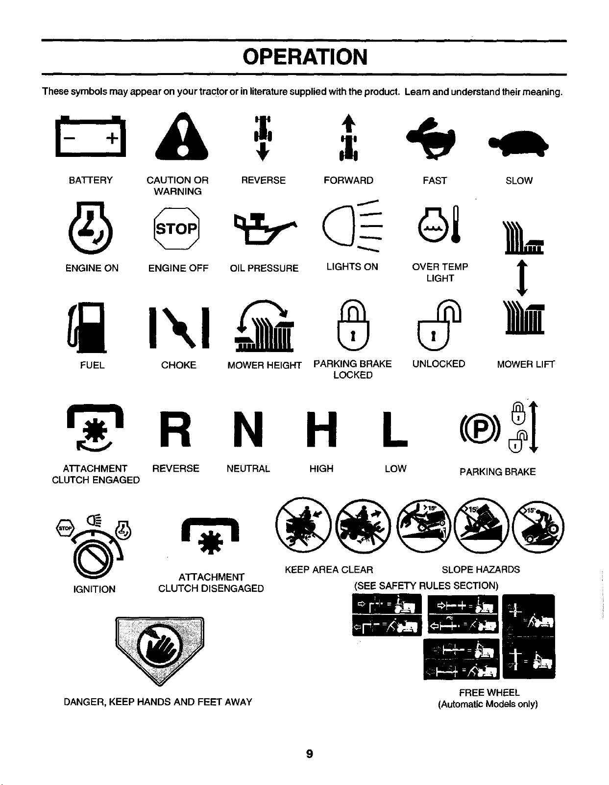
These symbols may appear on your tractor or in literaturesupplied with the product. Learn and understand theirmeaning.
BATFERY CAUTION OR REVERSE FORWARD FAST SLOW
WARNING
ENG,NEONENG,NEOFFO,,PRESSURE,,GHTSONO%_MP t
FUEL CHOKE MOWER HEIGHT PARKING BRAKE UNLOCKED MOWER LIFT
LOCKED
N H L
ATTACHMENT REVERSE
CLUTCH ENGAGED NEUTRAL HIGH LOW PARKING BRAKE
KEEP AREA CLEAR SLOPE HAZARDS
ATFACHMENT
IGNITION CLUTCH DISENGAGED (SEE SAFETY RULES SECTION)
DANGER, KEEP HANDS AND FEET AWAY FREEWHEEL
(Automatic Modelsonly)
9
OPERATION
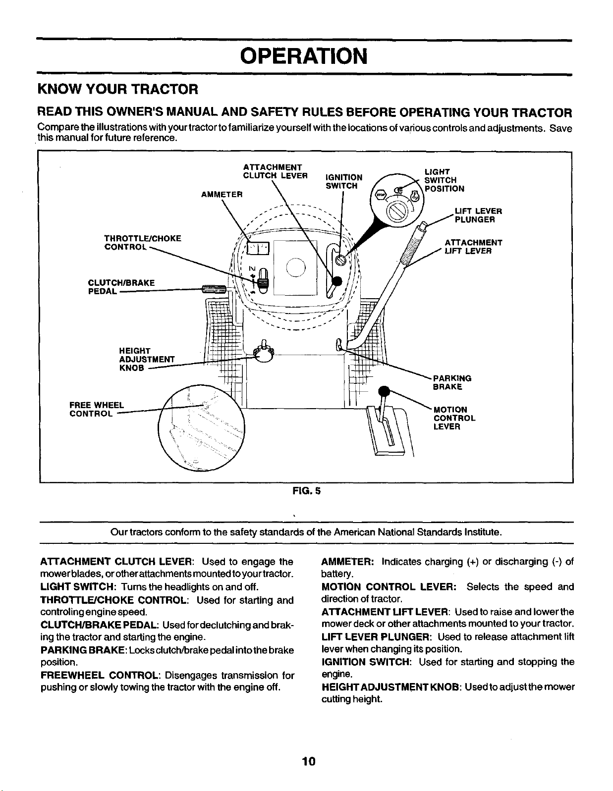
KNOW YOUR TRACTOR
READ THIS OWNER'S MANUAL AND SAFETY RULES BEFORE OPERATING YOUR TRACTOR
Compare the illustrationswith yourtractor tofamiliadzeyourself withthelocations ofvariouscontrols and adjustments. Save
this manual for future reference.
THROTTL_CHOKE
ATTACHMENT LIGHT
CLUTCH LEVER IGNITION SWITCH
SWITCH POSITION
AMMETER
LIFT LEVER
ATTACHMENT
LEVER
CLUTCHIBRAKE
PEDAL
HEIGHT
ADJUSTMENT
KNOB
FREE WHEEL
CONTROL
_PARKING
BRAKE
iCONTROL
LEVER
FIG. 5
Our tractors conform to the safety standards of the American National Standards Institute.
A'n'ACHMENT CLUTCH LEVER: Used to engage the
mower blades, orotherattachments mounted toyourtractor.
LIGHT SWITCH: Turns the headlightson and off.
THROTTLE/CHOKE CONTROL: Used for starting and
controling engine speed.
CLUTCH/BRAKE PEDAL: Used fordeclutching and brak-
ingthe tractor and starting the engine.
PARKING BRAKE: Locksclutch/brake pedalintothe brake
position.
FREEWHEEL CONTROL: Disengages transmission for
pushing or slowly towing the tractor with the engine off.
AMMETER: Indicates charging (+) or discharging (-) of
battery.
MOTION CONTROL LEVER: Selects the speed and
directionof tractor.
ATTACHMENT LIFT LEVER: Used toraise and lower the
mower deck or other attachments mounted toyour tractor,
LIFT LEVER PLUNGER: Used to release attachment lift
lever when changing itsposition.
IGNITION SWITCH: Used for starting and stopping the
engine.
HEIGHT ADJUSTMENT KNOB: Used to adjustthe mower
cutting height.
10
OPERATION
The operation of any tractor can result in foreign objects thrown into the eyes, which can
result in severe eye damage. Always wear safety glasses or eye shields while operating
your tractor or performing any adjustments or repairs. We recommend awide vision
safety mask over spectacles or standard safety glasses.
HOW TO USE YOUR TRACTOR
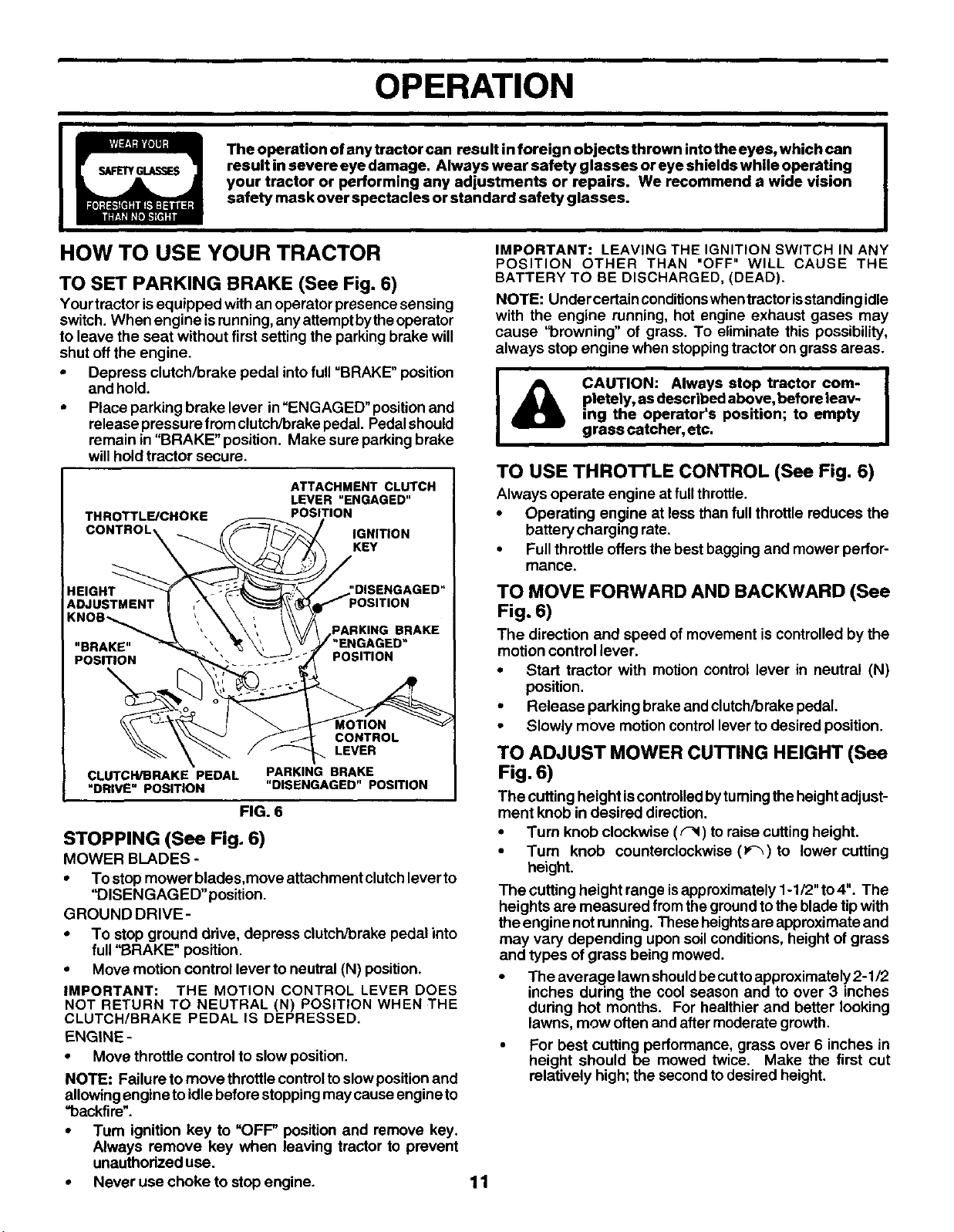
TO SET PARKING BRAKE (See Fig. 6)
Your tractor isequipped with an operator presence sensing
switch. When engine is running, any attempt bythe operator
to leave the seat without first setting the parking brake will
shut off the engine.
• Depress clutch/brake pedal into full "BRAKE" position
and hold.
•Place parking brake lever in "ENGAGED" position and
release pressure from clutch/brake pedal. Pedal should
remain in "BRAKE" position. Make sure parking brake
will hold tractor secure.
ATTACHMENT CLUTCH
LEVER "ENGAGED"
THROTTLE/CHOKE POSITION
CONTROL_ IGNITIONKEY
'DISENGAGED"
BRAKE
POSITION
CONTROL
LEVER
CLUTCH/BRAKE PEDAL
"DRIVE" POSITION PARKING BRAKE
"DISENGAGED" PosmoN
FIG. 6
STOPPING (See Fig. 6)
MOWER BLADES -
To stop mower blades,move attachment clutchlever to
"DISENGAGED" position.
GROUND DRIVE-
• To stop ground drive, depress clutch/brake pedal into
full "BRAKE" position.
•Move motion control lever to neutral (N) position.
IMPORTANT: THE MOTION CONTROL LEVER DOES
NOT RETURN TO NEUTRAL (N) POSITION WHEN THE
CLUTCH/BRAKE PEDAL IS DEPRESSED.
ENGINE -
• Move throttle control to slow position.
NOTE: Failure to move throttle control to slow position and
allowing engine to idle before stopping may cause engine to
_backfire".
• Turn ignition key to "OFF" position and remove key.
Always remove key when leaving tractor to prevent
unauthodzed use.
•Never use choke to stop engine.
IMPORTANT: LEAVING THE IGNITION SWITCH IN ANY
POSITION OTHER THAN "OFF" WILL CAUSE THE
BATTERY TO BE DISCHARGED, (DEAD).
NOTE: Under certainconditionswhentractorisstandingidle
with the engine running, hot engine exhaust gases may
cause "browning" of grass. To eliminate this possibility,
always stop engine when stoppingtractor on grass areas.
ICAUTION: Always stop tractor com-
pletely, as described above, before leav-
ing the operator's position; to empty
grass catcher, etc.
TO USE THROTrLE CONTROL (See Fig. 6)
Always operate engine at fullthrottle.
•Operating engine at lessthan fullthrottle reduces the
battery charging rate.
•Full throttle offers the bestbagging and mower perfor-
mance.
TO MOVE FORWARD AND BACKWARD (See
Fig. 6)
The direction and speed ofmovement iscontrolled bythe
motion control lever.
•Start tractor with motion control lever in neutral (N)
position.
•Release parking brake and clutch/brake pedal.
•Slowly move motion controllever to desired position.
TO ADJUST MOWER cUTrlNG HEIGHT (See
Fig. 6)
The cutting height iscontrolledbyturningthe height adjust-
ment knob in desired direction.
•Turn knob clockwise (F_ ) to raise cutting height.
•Turn knob counterclockwise (P'_) to lower cutting
height.
The cutting height range isapproximately 1-1/2" to4". The
heights are measured fromthe groundtothe blade tip with
the engine not running. These heightsare approximate and
may vary depending upon soilconditions, height of grass
and types ofgrass being mowed.
•The average lawn shouldbe cuttoapproximately 2-1/2
inches during the cool season and to over 3 inches
dudng hot months. For healthier and better looking
lawns, mow often and after moderate growth.
•For best cuttingperforrnance, grass over 6 inches in
height should be mowed twice. Make the first cut
relatively high; the second todesired height.
11

OPERATION
TO OPERATE ON HILLS
TO ADJUST GAUGE WHEELS (See Fig. 9)
Gauge wheels are propedy adjusted when they are slightly
offthe ground when mower isat the desired cutting height in
operating position, Gauge wheels then keep the deck in
proper position to help prevent scalping in most terrain
conditions.
•Adjust gauge wheels with tractor on a flat level surface.
•Adjust mower to desired cutting height (See '_ro AD-
JUST MOWER CUI-I-ING HEIGHT" in the Operation
section of this manual).
• With mower in desired height of cut position, gauge
wheels should be assembled so they are slightly off the
ground, install gauge wheel in appropriate hole with
shoulder bolt, 3/8 washer, and 3/8-16 Iocknut and tighten
securely.
• Repeat for opposite side installing gauge wheel in same
adjustment hole.
GUAGE WHEEL ,_\ _ f_;,--_ I
MOUNTING " /_ \ _._,._/_
LGCKNUTf I; P'_I SHOULDER
SWASHER/
GAUGE WHEEL"
FIG. 7
TO OPERATE MOWER (See Fig. 8)
Your tractorisequipped with anoperator presence sensing
switch. Any attempt by the operator to leave the seat with
the engine running and the attachment clutch engaged will
shut offthe engine.
•Select desired height of cut.
•Lower mower with attachment liftcontrol.
•Start mower blades by engaging attachment clutch
control
•TO STOP MOWER BLADES -disengage attachment
clutch control.
& CAUTION: Donotdriveupordownhills I
with slopes greater than 15° and do not
drive across any slope.
Choose the slowest speed before starting up or down
hills.
•Avoid stopping or changing speed on hills.
•If slowing is necessary, move throttle control lever to
slowerposition.
•If stopping is absolutely necessary, push clutch/brake
pedal quickly to brake position and engage parking
brake.
• Move motion control lever to neutral (N) position.
IMPORTANT: THE MOTION CONTROL LEVER DOES
NOT RETURN TO NEUTRAL (N) POSITION WHEN THE
CLUTCH/BRAKE PEDAL IS DEPRESSED.
•To restart movement, slowly release parking brake and
clutch/brake pedal.
•Slowly move motion control lever to slowest setting.
•Make all tums slowly.
TO TRANSPORT (See Figs. 5 and 9)
When pushingor towing your tractor, be sure todisengage
transmission by placing freewheel control in freewheeling
position.Free wheel controlislocated at therear drawbar of
tractor.
•Raise attachment lift to highest position with attach-
ment liftcontrol.
•Pull freewheel control out and down into the slot and
release so it isheld in the disengaged position.
•Do not push ortow tractor at more than two (2) MPH.
•To reengagetransmission, reverse above procedure.
NOTE: To protect hood from damage when transporting
yourtrectoron atruck ora trailer, be sure hood isclosedand
securedtotractor. Use an appropriate means oftyinghood
totractor (rope, cord, etc.).
CAUTION: Do not operate the mower
without either the entire grass catcher,
on mowers so equipped, or the dis-
charge guard in place.
/
/
"ENGAGED" POSITION
ATTACHMENT
LEVER
": HIGH POSI-
,_ION
/_ LOW
POSITION
CLUTCH LEVER __-
"DISENGAGED" .
POSITION "_ ill
DISCHARGE
GUARD
/
i
FIG. 9
TOWING CARTS AND OTHER ATTACHMENTS
Tow only the attachments that are recommended by and
comply with specifications of the manufacturer of your
tractor. Use common sense when towing. Too heavy ofa
load, whileon a slope, isdangerous. Tires can lose traction
withthegroundand cause you tolosecontrolofyourtractor.
FIG. 8 12
OPERATION
BEFORE STARTING THE ENGINE
CHECK ENGINE OIL LEVEL (See Fig. 14)
•The engine in yourtractor has been shipped, from the
factory, already filled with summer weight oil.
•Check engine oilwithtractor on level ground.
•Unthread and remove oil fillcap/dipstick; wipe oil off.
Reinsert the dipstick intothetube and restoilfill cap on
thetube. Do not thread thecap ontothetube. Remove
and read oil level. If necessary, add oil until "FULL"
mark on dipstick is reached, Do not overfill.
•For cold weather operation you shouldchange oil for
easier starting (See "OIL VISCOSITY CHART' in the
Customer Responsibilities sectionofthis manual).
•To change engine oil, see the Customer Responsibili-
ties section in this manual.
ADD GASOLINE
•Fill fuel tank. Use fresh, clean, regular unleaded
gasoline with a minimum of 87 octane. (Use of leaded
gasoline will increase carbon and lead oxide deposits
and reduce valve life). Do not mix oil with gasoline.
Purchase fuel in quantities that can be used within 30
days to assure fuel freshness.
IMPORTANT: WHEN OPERATING IN TEMPERATURES
BELOW 32°F(0°C), USE FRESH, CLEAN WINTER GRADE
GASOLINE TO HELP INSURE GOOD COLD WEATHER
STARTING.
WARNING: Experience indicatesthatalcoholblended fuels
(called gasohol or using ethanol or methanol) can attract
moisture which leads to separation and formation of acids
during storage. Acidic gas can damage the fuel system of
an engine while in storage. To avoid engine problems, the
fuel system should be emptied before storageof 30 days or
longer. Drain the gastank, starttheengine and letitrununtil
the fuel lines and carburetor are empty. Use fresh fuel next
season. See Storage Instructionsfor additionalinformation.
Never use engine or carburetor cleaner productsinthe fuel
tank or permanent damage may occur.
&|
CAUTION: Fill to bottom of gas tank I
filler neck. Do not overfill. Wipe off any I
spilled oil or fuel. Do not store, spill or
use gasoline near an open flame.
TO START ENGINE (See Fig. 5)
When starting the engine forthefirstUmeor ifthe engine has
run out of fuel, it willtake extra crankingtime to move fuel
from the tank to the engine.
• Besure freewheelcontrolisin thetransmissionengaged
position.
• Sit on seat in operating position,depress clutch/brake
pedal and set parking brake.
• Place motion controllever in neutral (N) position.
• Move attachment clutchto "DISENGAGED" position,
•Move throttle control to choke position.
NOTE: Before starting, read the warm and cold starting
procedures below.
Insertkey into ignition and turnkey clockwise to "START"
position and release key as soonas engine starts. Do not
run starter continuously for more than fifteen seconds per
minute. If the engine does not start after several at-
tempts, move throttle controlto fast position, wait afew
minutes and try again. If engine still does not start, move
the throttle control back to the choke position and retry.
WARM WEATHER STARTING (50° Fand above)
• When engine starts, move the throttle control to the fast
position.
• The attachments and ground drive can now be used. If
the engine does not accept the load, restart the engine
and allow it towarm up for one minute using the choke as
described above.
COLD WEATHER STARTING (50 ° F and below)
• When engine starts, allow engine to run with the throttle
controlinthechokepositionuntiltheengine runsroughly,
then move throttle control to fast position. This may
requirean engine warm-up periodfrom several seconds
to several minutes, depending on the temperature.
AUTOMATIC TRANSMISSION WARM UP
•Before drivingthe unitincoldweather, the transmission
should bewarmed up as follows:
•Be sure the tractoris on level ground.
•Place the motioncontrol lever in neutral, Release
the parking brake and let the clutch/brake
slowly returntooperating position.
•Allow one minute for transmission towarm up. This
can be doneduringthe engine warm up period.
•The attachments can also be used during the engine
warm-up period afterthe transmission has been warmed
up.
NOTE: If at a high altitude (above 3000 feet) or in cold
temperatures (below 32 F) the carburetor fuel mixture may
need to be adjusted for best engine performance. See "TO
ADJUST CARBURETOR" in the Service and Adjustments
section of this manual.
PURGE TRANSMISSION
13
]_1) AUTION: Neverengageordisengage ]
freewheel lever while the engine is run-
ning.
To ensure proper operation and performance, it is recom-
mended that the transmission be purged before operating
tractor for the first time, This procedure will remove any
trapped air inside the transmission which may have devel-
oped duringshipping ofyour tractor.
IMPORTANT: SHOULD YOUR TRANSMISSION REQUIRE
REMOVAL FOR SERVICE OR REPLACEMENT, IT
SHOULD BEPURGED AFTER REINSTALLATION BEFORE
OPERATING THE TRACTOR.
•Place tractor safelyonlevel surface with engine offand
parking brake set.
•Disengage transmissionby placingfreewheel control in
freewheeling position(See "TO TRANSPORT" in this
section of manual).
•Sitting in thetractorseat, start engine. After the engine
is running, move throttle control to slow position. With
motion control lever in neutral (N) position, slowly
disengage clutch/brake pedal.
OPERATION
•Move motion control lever to full forward positionand
hold for five (5) seconds. Move lever to full reverse
position and hold for five (5) seconds. Repeat this
procedure three (3) times.
NOTE: During this procedure there willbe no movement of
ddve wheels, The air is being removed from hydraulic ddve
system.
• Move motion control lever to neutral (N) position. Shut-
off engine and set parking brake.
• Engage transmission by placing freewheel control in
driving position (See "ro TRANSPORT" in this section
ofmanual).
• Sitting inthe tractor seat, start engine. After the engine
isrunning, move throttle control to half (1/2) speed.With
motion control lever in neutral (N) position, slowly
disengage clutch/brake pedal,
• Slowly move motion control lever forward, after the
tractor moves approximately five (5) feet, slowly move
motion controllever to reverse position. After the tractor
moves approximately five (5) feet return the motion
control lever to the neutral (N) position. Repeat this
procedure with the motion control lever three (3) times.
• Your tractor is now purged and now ready for normal
operation.
MOWING TIPS
• Mower should be propedy leveled for best mowing
performance. See "TO LEVEL MOWER HOUSING" in
the Service and Adjustments section of this manual.
The left hand side ofmower should be used fortrimming.
• Drive sothat clippings are discharged onto the areathat
has been cut. Have the cut area to the dght of the
machine. This will result in a more even distribution of
clippings and more uniform cutting.
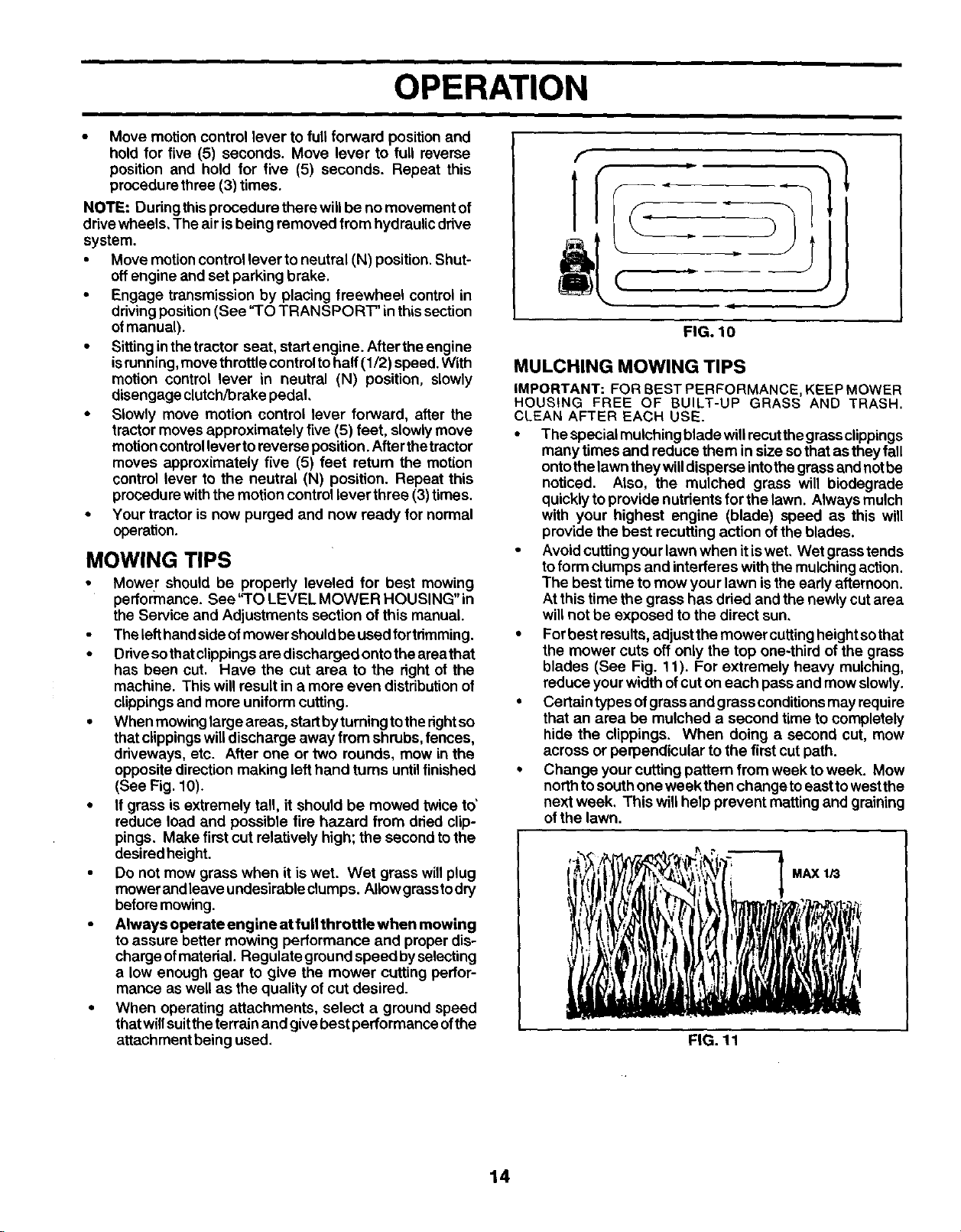
• When mowing large areas, start by turning to the rightso
that clippings will discharge away from shrubs, fences,
driveways, etc. After one or two rounds, mow in the
opposite direction making left hand turns until finished
(See Fig. 10).
• If grass is extremely tall, it should be mowed twice to'
reduce load and possible fire hazard from dried clip-
pings. Make first cut relatively high; the second to the
desired height.
• Do not mow grass when it is wet. Wet grass will plug
mower andleave undesirable clumps. AIIowgrasstodry
before mowing.
•Always operate engine at fullthrottle when mowing
to assure better mowing performance and proper dis-
charge ofmaterial. Regulate ground speed byselecting
a low enough gear to give the mower cutting perfor-
mance as well as the quality of cut desired.
•When operating attachments, select aground speed
thatwillsuittheterrain and give best performance ofthe
attachment being used,
f
fP
(
FIG. 10
MULCHING MOWING TIPS
IMPORTANT: FOR BEST PERFORMANCE, KEEP MOWER
HOUSING FREE OF BUILT-UP GRASS AND TRASH.
CLEAN AFTER EACH USE.
• The special mulching blade will recut the grass clippings
many times and reduce them in size sothat as they fall
onto the lawn they will disperse into the grass and not be
noticed. Also, the mulched grass will biodegrade
quickly to provide nutdents for the lawn. Always mulch
with your highest engine (blade) speed as this will
provide the best recutting action of the blades.
• Avoid cutting your lawn when itis wet. Wet grass tends
to form clumps and interferes with the mulching action.
The best time to mow your lawn is the early afternoon.
At this time the grass has dried and the newly cut area
will not be exposed to the direct sun,
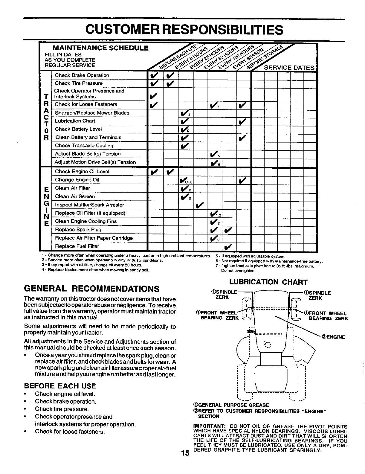
•For best results, adjust the mower cutting height so that
the mower cuts off only the top one-third of the grass
blades (See Fig. 11). For extremely heavy mulching,
reduce your width ofcut on each pass and mow slowly.
• Certain types of grass and grass conditionsmay require
that an area be mulched a second time to completely
hide the clippings. When doing a second cut, mow
across or perpendicular to the first cut path.
Change your cutting pattern from week to week. Mow
north to south one week then change to east to west the
next week, This willhelp prevent matting and graining
of the lawn.
MAX 1i3
FIG. 11
14
CUSTOMER RESPONSIBILITIES
MAINTENANCE SCHEDULE .__ __,_'_,_ ._* f
F.LL,.OATEB
ABYouOOMPL E .......
REGULARSERVICE /__7"_._7"S ERViCE DATES
Check Brake Operation _
Check Tire Pressure
Check Operator Presence and
T Interlock Systems
Check for Loose Fasteners _7 If
cA Sharpen/Replace Mower Blades _4
oT Lubrication Chart i# #
Cheek Battery Level
RClean Battery and Terminals V'
Check Transaxle Cooling I_
Adjust Blade Belt(s)Tension V'5
,/°
Adjust Motion Ddve Belt(s) Tension
Check Engine Oil Level _V'
Change Engine Oil 1_1,2,3 V'
NE Clean Air Filter
Clean Air Screen
G Inspect Muffler/Spark Arrester _#
Replace Oil Filter (If equipped) _,_
N Clean Engine Cooling Fins _2
Replace Spark Plug I_
Replace Air Filter Paper Cartridge _2
Replace Fuel Filter _#
1 - Change more often when operating under aheavy load or in high ambient temperatures. 5 - If equipped withadjustable system,
2 - Sendce more often when operating in dirty or dusty conditions, 6 -Not required if equipped with maintenance-free battery.
3-If equipped with oilfilter, change oil every 50 hours. 7 - 33ghten front axle pivot bolt to 35 ft,ifbs, maximum.
4 - Replace blades more olten when mowing in sandy soil. Do not overtighten.
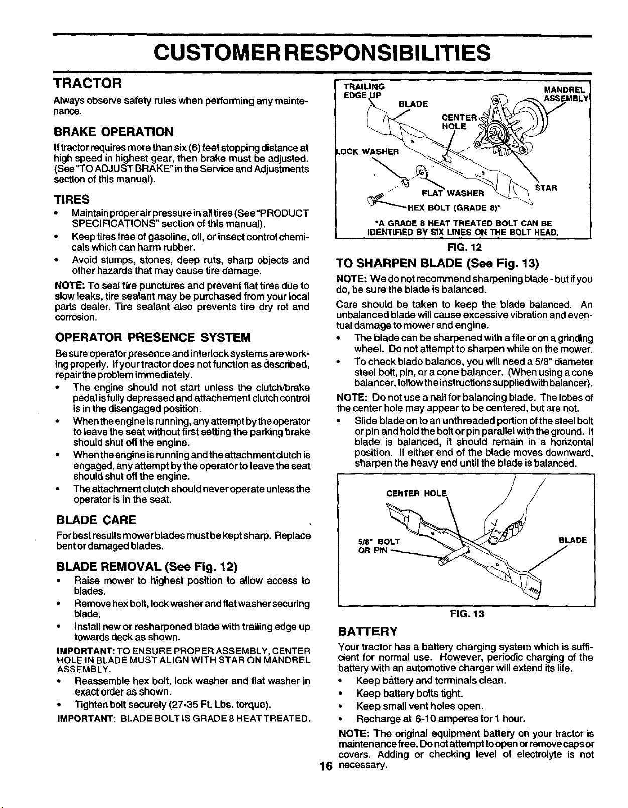
GENERAL RECOMMENDATIONS
The warranty on this tractordoes notcover itemsthat have
been subjected to operatorabuse ornegligence. To receive
fullvalue from the warranty, operatormust maintain tractor
as instructed in this manual.
Some adjustments will need to be made periodically to
properly maintain yourtractor.
All adjustments in the Service and Adjustments section of
this manual should be checked at leastonce each season.
•Once a yearyou shouldreplacethespark plug,clean or
replace air filter, and checkblades and beltsfor wear. A
newspark plug and clean air filterassure preper air-fuel
mixture and helpyourengine runbetter and last longer.
BEFORE EACH USE
•Check engine oil level.
•Check brake operation.
•Check tire pressure.
•Check operator presence and
intedock systems for properoperation.
•Check for loose fasteners.
LUBRICATION CHART
ZERK ZERK
_)FRONT WHEE
BEARING ZERK ' "(_FRONT WHEEL
BEARING ZERK
_GENERAL PURPOSE GREASE
(_REFER TO CUSTOMER RESPONSIBILITIES "ENGINE _
SECTION
IMPORTANT: DO NOT OIL OR GREASE THE PIVOT POINTS
WHICH HAVE SPECIAL NYLON BEARINGS. VISCOUS LUBRI-
CANTS WILL ATTRACT DUST AND DIRT THAT WILL SHORTEN
THE LIFE OF THE SELF-LUBRICATING BEARINGS, IF YOU
FEEL THEY MUST BE LUBRICATED, USE ONLY A DRY, POW-
15 DERED GRAPHITE TYPE LUBRICANT SPARINGLY.
CUSTOMER RESPONSIBILITIES
TRAILING MANDREL
ASSEMRL_
TRACTOR
Always observe safety rules when performing any mainte-
nance.
BRAKE OPERATION
Iftractorrequiresmore than six(6) feet stopping distanceat
high speed in highest gear, then brake must be adjusted.
(See "TO ADJUST BRAKE" inthe Service and Adjustments
sectionof this manual).
TIRES
•Maintainproperairpressure inalltires (See"PRODUCT
SPECIFICATIONS" section of this manual).
•Keep tires free of gasoline, oil, or insect controlchemi-
cals whichcan harm rubber.
•Avoid stumps, stones, deep ruts, sharp objects and
other hazards that may cause tire damage.
NOTE: To seal tire punctures and prevent flattires due to
slow leaks, tire sealant may be purchased from your local
parts dealer. Tire sealant also prevents tire dry rot and
corrosion.
OPERATOR PRESENCE SYSTEM
Besure operatorpresence and interlocksystems are work-
ingproperly. Ifyourtractor does not function as descdbed,
repairthe problemimmediately.
•The engine should not start unless the clutch/brake
pedal istully depressed and attachement clutchcontrol
isin the disengaged position.
•When theengine isrunning, any attempt bytheoperator
toleave the seat without first setting the parking brake
shouldshut offthe engine.
•When theengine isrunningand the attachment clutchis
engaged, any attempt bythe operator to leave the seat
shouldshut offthe engine.
• The attachment clutchshould never operate unlessthe
operator isin the seat.
BLADE CARE
Forbestresultsmower blades must be keptsharp. Replace
bent ordamaged blades.
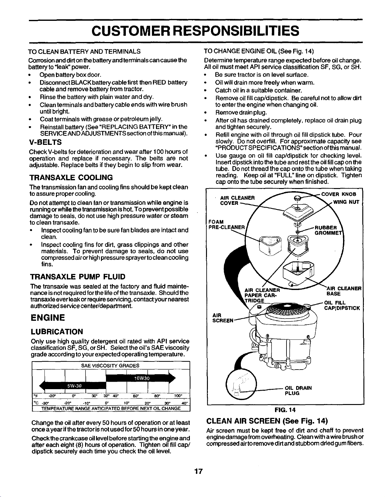
BLADE REMOVAL (See Fig. 12)
•Raise mower to highest position to allow access to
blades.
•Remove hexbolt, lockwasher and flatwasher securing
blade.
•Install new or resharpened blade with trailing edge up
towards deck as shown.
IMPORTANT: TO ENSURE PROPER ASSEMBLY, CENTER
HOLE IN BLADE MUST ALIGN WITH STAR ON MANDREL
ASSEMBLY.
•Reassemble hex bolt, lock washer and flat washer in
exact order as shown.
•Tighten bolt securely (27-35 Ft. Lbs. torque).
IMPORTANT: BLADE BOLT IS GRADE 8 HEAT TREATED.
BLADE
CENTER,
HOLE
FLAT WASHER
HEX BOLT(GRADE 8)
STAR
*A GRADE 8 HEAT TREATED BOLT CAN BE
IDENTIFIED BY SIX LINES ON THE BOLT HEAD.
FIG. 12
TO SHARPEN BLADE (See Fig. 13)
NOTE: We do not recommend sharpening blade- but ifyou
do, be sure the blade is balanced.
Care should be taken to keep the blade balanced. An
unbalanced blade will cause excessive vibrationand even-
tual damage to mower and engine.
• The blade can be sharpened with a file or on a gdnding
wheel. Do not attempt to sharpen while on the mower.
• To check blade balance, you will need a 5/8" diameter
steel bolt, pin, or a cone balancer. (When using a cone
balancer, follow the instructions suppliedwith balancer).
NOTE: Do not use a nail for balancing blade. The lobes of
the center hole may appear to be centered, but are not.
• Slide blade on to an unthreaded portion ofthe steel bolt
or pin and hold the bolt or pin parallel with the ground. If
blade is balanced, it should remain in a horizontal
position. If either end of the blade moves downward,
sharpen the heavy end until the blade is balanced.
CENTER HOLE
5/8" BOLT BLADE
OR
16
FIG. 13
BATTERY
Your tractor has abattery charging system which is suffi-
cient for norma( use. However, pedodic charging of the
battery with an automotive charger willextend itslife.
* Keep battery and terminals clean.
• Keep battery bolts tight.
•Keep small vent holes open.
• Recharge at 6-10 amperes for I hour.
NOTE: The odginal equipment battery on your tractor is
maintenance free. Do notattempt toopen orremove capsor
covers. Adding or checking level of electrolyte is not
necessary.
CUSTOMER RESPONSIBILITIES
TO CLEAN BATTERY AND TERMINALS
Corrosionand dirtonthebattery and terminals can cause the
battery to=leak" power.
•Open battery box door.
•DisconnectBLACK battery cable first then RED battery
cable and remove battery from tractor.
•Rinse the battery withplain water and dry.
•Clean terminals and battery cable ends withwire brush
untilbright.
•Coat terminals with grease or petroleum jelly.
•Reinstall battery (See "REPLACING BATTERY" in the
SERVICE AND ADJUSTMENTS section of this manual).
V-BELTS
Check V-belts for deterioration and wear after 1O0 hours of
operation and replace if necessary. The belts are not
adjustable. Replace belts if they begin to slip from wear.
TRANSAXLE COOLING
The transmission fan and coolingfins should be kept clean
to assure propercooling.
Do notattempt toclean fan or transmission while engine is
runningorwhilethe transmissionishot.To prevent possible
damage toseals, do not use high pressure water or steam
to clean transaxle.
•Inspect coolingfan tobe sure fan blades are intact and
clean.
•Inspect cooling fins for dirt, grass clippings and other
materials. To prevent damage to seals, do not use
compressedair orhighpressuresprayer toclean cooling
fins.
TRANSAXLE PUMP FLUID
The transaxle was sealed at the factory and fluid mainte-
nance isnotrequired forthe lifeofthe transaxle. Should the
trensaxle everleak orrequireservicing,contact yournearest
authorized service center/department.
ENGINE
LUBRICATION
Only use high quality detergent oil rated with API service
classification SF, SG, orSH. Select the oil's SAE viscosity
grade accordingtoyour expected operating temperature.
SAE VISCOSITY GRADES
-20= (Y' 30°32_40°60" 80_ 100°
.30• .20_ .10_0o 10° 20 °30 °40°
TEMPERATURE RANGE ANTICIPATED BEFORE NEXT OIL CHANGE
Change the oilafter every 50 hours of operation or at least
once a yearif thetractorisnotused for 50 hours inone year.
Check thecrankcase oillevel beforestarting the engine and
after each eight (8) hours of operation. Tighten oilfill cap/
dipstick securely each time you check the oil level.
TO CHANGE ENGINE OIL (See Fig. 14)
Determine temperature range expected before oilchange.
All oilmust meet API service classification SF, SG, or SH.
•Be sure tractor is on level surface.
•Oil willdrain more freely when warm.
•Catch oilina suitable container.
•Remove oilfill cap/dipstick. Be careful not to allow dirt
to enter the engine when changing oil.
•Remove drainplug.
• After oilhas drained completely, replace oildrain plug
and tighten securely.
•Refill engine with oil through oil fill dipstick tube. Pour
slowly. Do not overfill. For approximate capacity see
"PRODUCT SPECIFICATIONS" sectionofthismanual.
• Use gauge on oil fill cap/dipstick for checking level.
Insert dipstickintothe tube and rest theoilfill capon the
tube. Do notthread the cap onto the tube when taking
reading. Keep oilat "FULU' line on dipstick. Tighten
cap ontothetube securely when finished.
AIR CLEANER
COVER
KNOB
=OAM
PRE-CLEANER
AIR
FILL
CAP:DIPSTICK
DRAIN
PLUG
FIG. 14
CLEAN AIR SCREEN (See Fig. 14)
Air screen must be kept free of dirt and chaff to prevent
engine damage fromoverheating. Clean with awire brushor
compressed airto remove dirtand stubbornddedgum fibers.
17
CUSTOMER RESPONSIBILITIES
IAIR FILTER (See Fig. 14)
Yourengine willnot runproperly using a dirtyair filter. Clean
the foam pre-cleaner after every 25 hours of operation or
every season. Service paper cartridge every 100 hours of
operation or every season, whichever occursfirst.
Service air cleaner more often under dusty conditions.
• Remove knob and cover.
• Remove wing nut and air cleaner from base.
TO SERVICE PRE-CLEANER
•Slide foam pre-cleaner offcartridge.
•Wash itin liquid detergent and water.
•Squeeze itdry in a clean cloth. Allow it todry.
•Saturete itinengine OILWrap itinclean, absorbentcloth
and squeeze to remove excess oil.
TO SERVICE CARTRIDGE
•Replace a dirty, bent, or damaged cartridge.
NOTE: Do notwash the paper cartridge or usepressurized
air, as this willdamage the cartridge.
•Reinstall the pre-cleaner (cleaned and oiled) over the
papercartridge.
•Reassemble air cleaner, wing nut, cover and tighten
knob securely.
CLEAN AIR INTAKE/COOLING AREAS
To insure proper cooling, make sure the grass screen,
cooling fins, and other external surfaces of the engine are
kept clean at all times.
Every 100 hours of operation (more often under extremely
dusty, dirty conditions), remove the blower housing and
other cooling shrouds. Clean the cooling fins and external
surfaces as necessary. Make sure the cooling shroudsare
reinstalled.
NOTE: Operating the engine with a blocked grass screen,
dirtyor pluggedcoolingfins,and/or cooling shroudsremoved
willcause engine damage due to overheating.
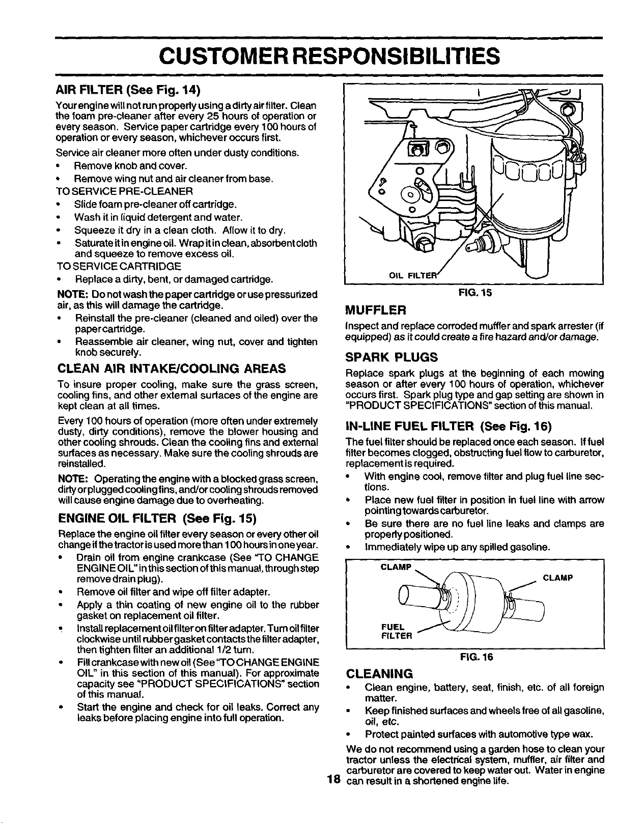
ENGINE OIL FILTER (See Fig. 15)
Replace the engine oilfilter every season or every otheroil
changeifthetractor isused more than 100 hoursinoneyear.
•Drain oil from engine crankcase (See "TO CHANGE
ENGiN E Ol[."in thissection ofthis manual, through step
remove drain plug).
•Remove oilfilter and wipe off filter adapter.
•Apply a thin coating of new engine oil to the rubber
gasket on replacement oilfilter.
Installreplacement oilfilteron tilter adapter. Turn oilfilter
clockwise untilrubber gasket contacts thetilteradapter,
then tighten filter an additional 1/2 turn.
•Fillcrankcase with new oil(See"TO CHANGE ENGINE
OIL" in this section of this manual). For approximate
capacity see "PRODUCT SPECIFICATIONS" section
of this manual.
•Start the engine and check for oil leaks. Correct any
leaks before placing engine into full operation.
OIL
FIG. 15
MUFFLER
Inspect and replace corroded mufflerand spark arrester (if
equipped) as itcould create atire hazard and/or damage,
SPARK PLUGS
Replace spark plugs at the beginning of each mowing
season or after every 100 hours of operation, whichever
occurs first. Spark plug type and gap setting are shown in
"PRODUCT SPECIFICATIONS" sectionofthis manual.
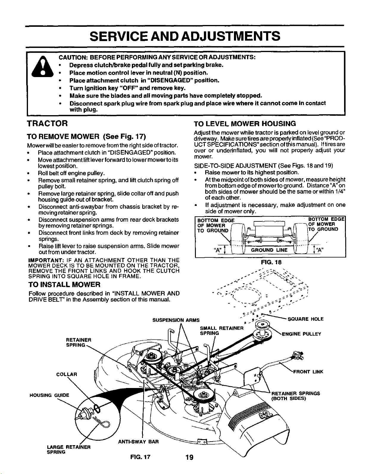
IN-LINE FUEL FILTER (See Fig. 16)
The fuel filter should be replaced once each season. If fuel
filter becomes clogged, obstructingfuel flowto carburetor,
raplecementis required.
•With engine cool, remove filter and plug fuel line sec-
tions.
•Place new fuel filter in position in fuel line with arrow
pointingtowards carburetor.
•Be sure there are no fuel line leaks and clamps are
propedy positioned.
•Immediately wipe up any spilledgasoline.
CLAMP
CLAMP
FUEL _
FILTER
FIG. 16
CLEANING
•Clean engine, battery, seat, finish, etc. of all foreign
matter.
•Keep finished surfaces and wheels free ofall gasoline,
oil, etc.
•Protect painted surfaces with automotive type wax.
We do not recommend using a garden hose to clean your
tractor unless the electrical system, muffler, air tilter and
carburetor are covered to keep water out. Water inengine
18 can result in a shortened engine life.
SERVICE AND ADJUSTMENTS
CAUTION: BEFORE PERFORMING ANY SERVICE OR ADJUSTMENTS:
Depress clutch/brake pedal fully and set parking brake.
Place motion control lever in neutral (N) position.
•Place attachment clutch in "DISENGAGED" position,
•Turn ignition key "OFF" and remove key.
•Make sure the blades and all moving parts have completely stopped.
•Disconnect spark plug wire from spark plug and place wire where it cannot come in contact
with plug.
TRACTOR TO LEVEL MOWER HOUSING
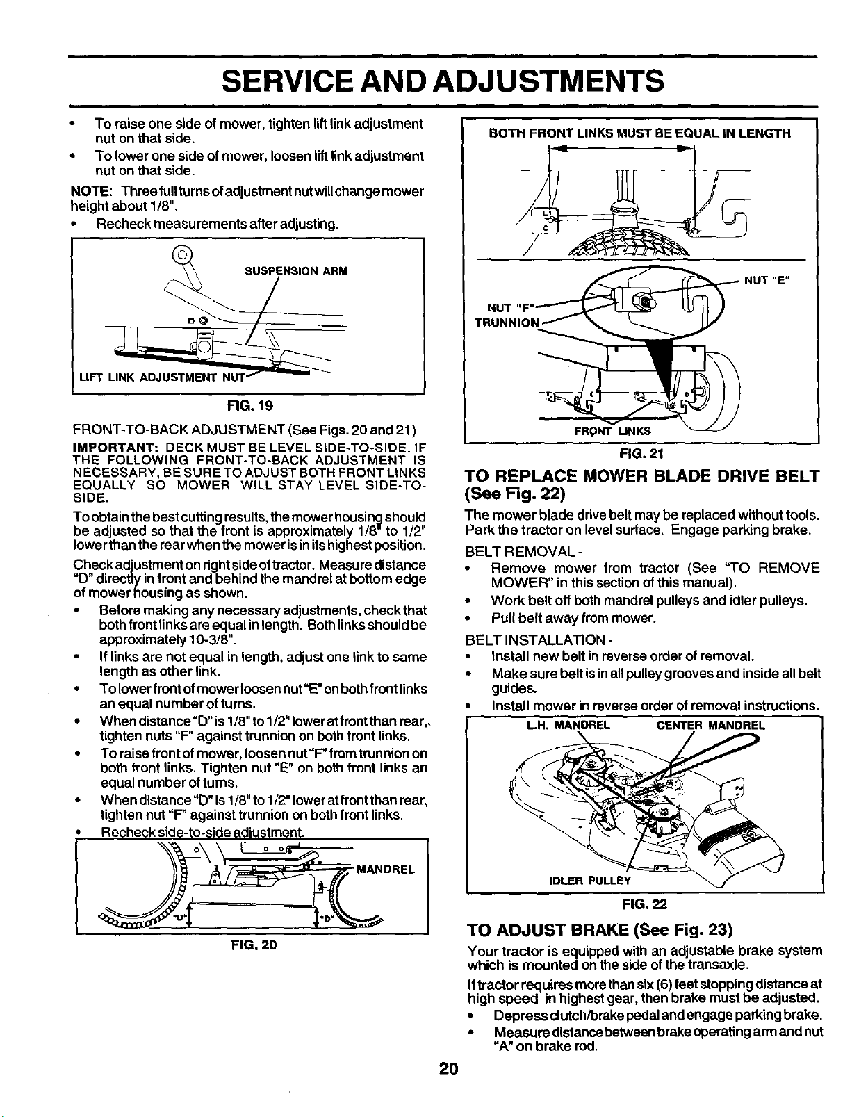
TO REMOVE MOWER (See Fig. 17)
Mowerwill be easier toremove from the rightside oftractor.
• Place attachment clutch in "DISENGAGED" position.
• Move attachment lift lever forward to lower mower to its
lowest position.
• Roll belt off engine pulley.
• Remove small retainer spring, and lift clutch spring off
pulley bolt.
• Remove large retainer spring, slide collar off and push
housingguide out of bracket.
•Disconnect anti-swaybar from chassis bracket by re-
movingretainer spring.
•Disconnectsuspension arms from rear deck brackets
by removingretainer springs,
•Disconnectfront links from deck by removing retainer
springs.
•Raise liftlever to raise suspension arms. Slide mower
outfrom under tractor.
IMPORTANT: IF AN ATTACHMENT OTHER THAN THE
MOWER DECK IS TO BE MOUNTED ON THE TRACTOR,
REMOVE THE FRONT LINKS AND HOOK THE CLUTCH
SPRING INTO SQUARE HOLE IN FRAME.
TO INSTALL MOWER
Follow procedure described in "INSTALL MOWER AND
DRIVE BEL'F' in the Assembly section of this manual.
RETAINER
SPRU
Adjust the mower while tractor is parked on level ground or
driveway. Make suretires are properly inflated(See "PROD-
UCT SPECIFICATIONS" section ofthismanual). Iftiresare
over or underinflated, you will not properly adjust your
mower.
SIDE-TO-SIDE ADJUSTMENT (See Figs. 18 and 19)
•Raise mower to its highest position.
•Atthe midpointofboth sides ofmower, measure height
from bottomedge of mower to ground. Distance"A"on
both sides of mower should be the same orwithin 1/4"
ofeach other.
•If adjustment is necessary, make adjustment on one
side of mower only.
BOTTOM EDGE BOTTOM EDGE I
OF MOWER /_ __ _/_-_-_OF MOWER
I I
FIG. 18
J<'/ _. ,_
"" _"_ SQUARE
SUSPENSION ARMS _.
SMALL RETAINER
SPRING
HOLE
COLLAR
HOUSING GUIDE_
FRONT LINK
SPRINGS
(BOTH SIDES)
ANTI-SWAY BAR
LARGE RETAINER
SPRING FIG. 17 19
SERVICE AND ADJUSTMENTS
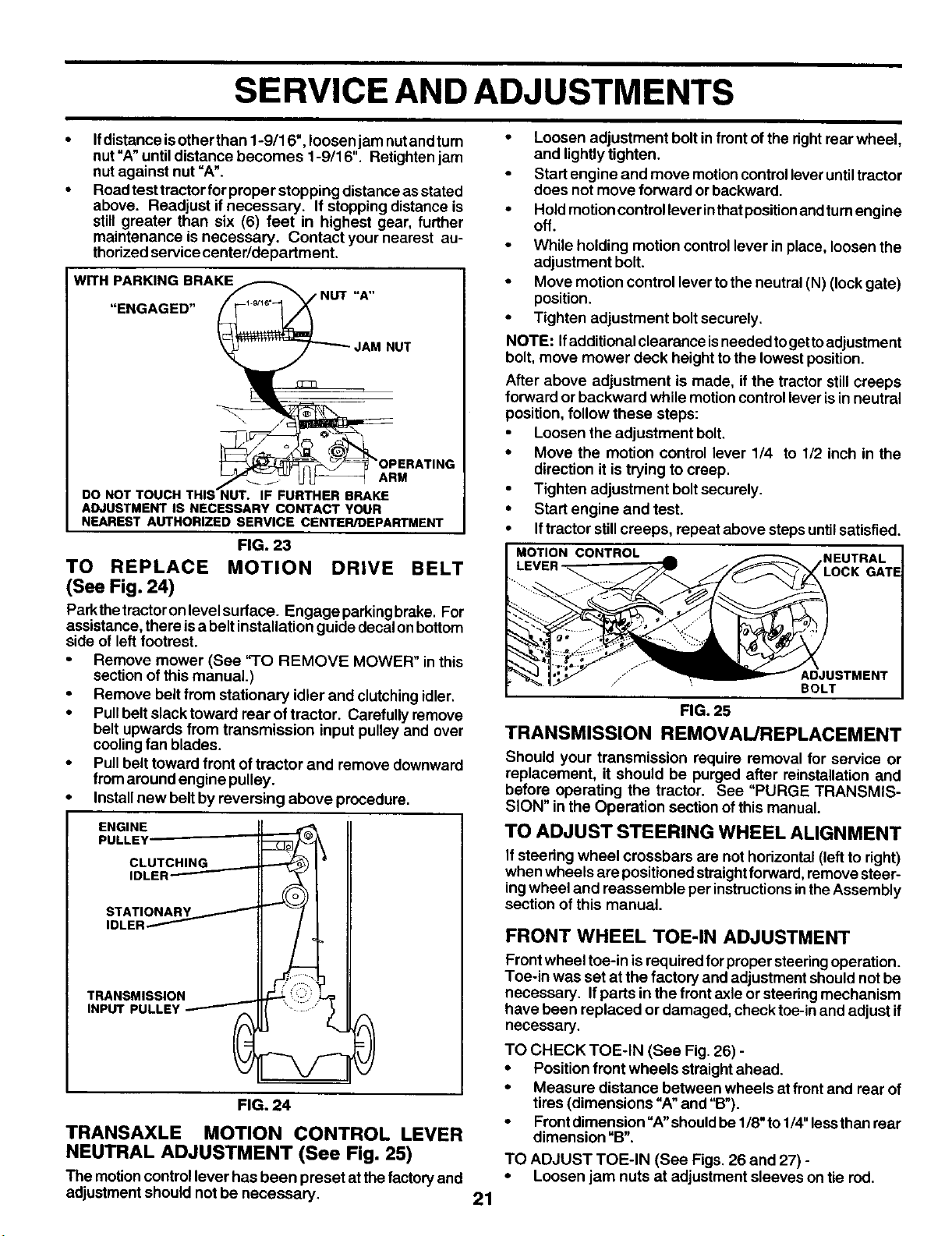
• To raise one side of mower, tighten liftlink adjustment
nut on that side.
• To lower one side ofmower, loosen liftlinkadjustment
nut on that side.
NOTE: Throe fullturnsofadjustmentnutwillchange mower
height about 1/8".
•Recheck measurements after adjusting.
SUSPENSION ARM
UFT
FIG. 19
FRONT-TO-SACK ADJUSTMENT (See Figs. 20 and 21 )
IMPORTANT: DECK MUST BE LEVEL SIDE-TO-SIDE. IF
THE FOLLOWING FRONT-TO-BACK ADJUSTMENT IS
N ECESSARY, BE SURE TO ADJUST BOTH FRONT LINKS
EQUALLY SO MOWER WILL STAY LEVEL SIDE-TO-
SIDE.
To obtain thebest cuttingresults,the mower housingshould
be adjusted so that the front is approximately 1/8" to 1/2"
lower than the rear when the mower isinitshighest position.
Check adjustment on rightside oftractor. Measure distance
"D" directly in front and behind the mandrel at bottom edge
of mower housing as shown.
•Before making any necessary adjustments, check that
bothfront linksare equal in length. Bothlinksshouldbe
approximately 10-3/8".
•Iflinks are not equal in length, adjust one link to same
length as other link.
•To lowerfront ofmower loosennut"E"onbothfront links
anequal number ofturns.
•When distance "D" is1/8"to1/2" Iowerat frontthan rear,.
tighten nuts "F" against trunnionon bothfront links.
•To raise front ofmower, loosen nut "F' from trunnionon
both front links. Tighten nut "E" on both front links an
equal number ofturns.
•When distance"b" is1/8"to1/2"loweratfront than rear,
tighten nut "F" against trunnion on both front links.
Recheck side-to-side adjustment.
"MANDREL
FIG, 20
BOTH FRONT LINKS MUST BE EQUALIN LENGTH
NUT
NUT "E"
FRONT LINKS
FIG. 21
TO REPLACE MOWER BLADE DRIVE BELT
(See Fig. 22)
The mower blade drivebelt may be replaced without tools.
Park the tractor on level surface, Engage parking brake.
BELT REMOVAL -
•Remove mower from tractor (See "TO REMOVE
MOWER" in this sectionof this manual).
•Work belt off bothmandrel pulleys and idler pulleys,
•Pull belt away from mower.
BELT INSTALLATION -
• Install new belt in reverse order of removal.
• Make sure belt is in all pulley grooves and inside all belt
guides.
Install mower in reverse order of removal instructions.
L.H. MANOREL CENTER MANDREL
2O
IDLER PULLEY
FIG. 22
TO ADJUST BRAKE (See Fig. 23)
Your tractor is equipped with an adjustable brake system
which is mounted on the side ofthe transaxle,
Iftractor requires morethan six (6) feet stopping distance at
high speed in highest gear, then brake must be adjusted.
•Depress clutch/brake pedal andengage parkingbrake.
•Measure distancebetween brake operating arm and nut
"A" on brake rod.
SERVICE AND ADJUSTMENTS
Ifdistance isother than 1-9/16", loosen jam nutand turn
nut "A" until distance becomes 1-9/16". Retighten jam
nut against nut =A".
Road test tractor for proper stopping distance as stated
above. Readjust if necessary. If stopping distance is
still greater than six (6) feet in highest gear, further
maintenance is necessary. Contact your nearest au-
thorized service center/department.
WITH PARKING BRAKE
"ENGAGED"
NUT
ARM
DO NOT TOUCH THIS_NUT. IF FURTHER BRAKE
ADJUSTMENT IS NECESSARY CONTACT YOUR
NEAREST AUTHORIZED SERVICE CENTER/DEPARTMENT
FIG. 23
TO REPLACE MOTION DRIVE BELT
(See Fig. 24)
Parkthetractoronlevelsufface. Engageparkingbrake. For
assistance, there isa belt installation guide decal on bottom
side of left footrest.
Remove mower (See "TO REMOVE MOWER" in this
section of this manual.)
• Remove belt from stationary idler and clutching idler.
• Pull belt slack toward rear of tractor. Carefully remove
belt upwards from transmission input pulley and over
cooling fan blades.
• Pull belt toward front of tractor and remove downward
from around engine pulley.
• Install new belt by reversing above procedure.
ENGINE _II
PULLEY Z_]_ II
CLUTCHING _I•
IDLER_ _[
,RANSMISSIGN
/NPUTPUL LEY
FIG. 24
TRANSAXLE MOTION CONTROL LEVER
NEUTRAL ADJUSTMENT (See Fig. 25)
The motioncontrollever has been preset at thefactory and
adjustment should not be necessary.
• Loosen adjustment bolt in front of the rightrear wheel,
and lightlytighten.
•Start engine and move motioncontrolleveruntiltractor
does not move forward orbackward.
•Hold motion controllever inthatpositionandturnengine
off.
•While holding motion controllever in place, loosen the
adjustment bolt.
•Move motion control lever tothe neutral (N) (lock gate)
position.
•Tighten adjustment boltsecurely.
NOTE: Ifadditional clearance isneeded togettoadjustment
bolt, move mower deck height to the lowest position.
After above adjustment is made, it the tractor stillcreeps
forward or backward while motioncontrollever isin neutral
position, follow these steps:
•Loosen the adjustment bolt.
•Move the motion control lever 1/4 to 1/2 inch in the
direction it is trying to creep.
•Tighten adjustment boltsecurely.
•Start engine and test.
•Iftractor stillcreeps, repeat above steps untilsatisfied.
MOTION CONTROL _NEUTRAL
LOCK GATE
21
..... ADJUSTMENT
"BOLT
FIG. 25
TRANSMISSION REMOVAL/REPLACEMENT
Should your transmission require removal for service or
replacement, it should be purged after reinstallation and
before operating the tractor. See "PURGE TRANSMIS-
SION" in the Operation sectionof this manual.
TO ADJUST STEERING WHEEL ALIGNMENT
If steering wheel crossbars are not horizontal (left to right)
when wheels are positioned straight forward, remove steer-
ing wheel and reassemble per instructions in the Assembly
section of this manual.
FRONT WHEEL TOE-IN ADJUSTMENT
Front wheel toe-in isrequired for proper steeringoperation.
Toe-in was set at the factory and adjustment shouldnot be
necessary. Ifparts inthe front axle or steering mechanism
have been replaced or damaged, check toe-in and adjust if
necessary.
TO CHECK TOE-IN (See Fig. 26) -
• Position front wheels straightahead.
•Measure distance between wheels at front and rear of
tires (dimensions "A"and "B").
•Front dimension =A"shouldbe 1/8"to1/4"lessthan rear
dimension "B".
TO ADJUST TOE-IN (See Figs. 26 and 27) -
•Loosen jam nuts at adjustment sleeves on tie rod,

SERVICE AND ADJUSTMENTS
•Adjust tie rod untildimension "A"is1/8" to 1/4" less than
dimension"B".
•Tighten jam nuts securely.
FRONT WHEEL CAMBER
The front wheel camber isnot adjustableon your tractor. If
damage has occurred to affect the front wheel camber,
contact your nearest authorizedservicecenter/department.
iFIG. 26
ADJUSTMENT SLEEVES
JAM NUTS
FIG. 27
TO REMOVE WHEEL FOR REPAIRS
(See Fig. 28)
•Block up axle securely.
•Remove axle cover, retainingringand washers toallow
wheel removal (rear wheel contains asquare key - Do
not lose).
•Repair tire and reassemble.
•On rearwheelsonly: align groovesinrearwheel huband.
axle. Insert square key.
•Replace washers and snap retaining ring securely in
axle groove.
•Replace axle cover.
NOTE: To seal tire punctures and prevent flat tires due to
slow leaks, tire sealant may be purchased from your local
parts dealer. Tire sealant also prevents tire dry rot and
corrosion.
WASHERS
.ETA,N,.Gk
AXLERING\/\ |lr/(( Ikll
FIG. 28
TO START ENGINE WITH A WEAK BATTERY
(See Fig. 29)
CAUTION: Lead-acid batteries generate
explosive gases. Keep sparks, flame
and smoking materials away from bat-
teries. Always wear eye protection when
around batteries.
If your battery is too weak to start the engine, it should be
recharged. If "jumper cables" are used for emergency
starting, follow this procedure:
IMPORTANT: YOUR TRACTOR IS EQUIPPED WITH A 12
VOLT NEGATIVE GROUNDED SYSTEM. THE OTHER
VEHICLE MUST ALSO BE A 12 VOLT NEGATIVE
GROUNDED SYSTEM. DO NOT USE YOUR TRACTOR
BATTERY TO START OTHER VEHICLES.
TO A'I-I'ACH JUMPER CABLES -
•Connect each endofthe RED cable tothe POSITIVE (+)
terminal ofeach battery,takingcare notto short againfit
chassis.
•Connectone endofthe BLACKcableto the NEGATIVE
(-) terminal offullycharged battery.
•Connect the other end of the BLACK cable to good
CHASSIS GROUND, away from fuel tank and battery.
TO REMOVE CABLES, REVERSE ORDER -
•BLACK cable firstfrom chassis and then from the fully
charged battery.
•RED cable lastfrom both batteries.
TERMINAL NEGATIVE TERMINAL
POSITIVE TERMI CHARGED
BATTERY
FIG. 29
REPLACING BA'I-rERY (See Fig. 30 and 31)
CAUTION: Do not short battery termi-
nals by allowing a wrench or any other
object to contact both terminals at the
same time, Before connecting battery,
remove metal bracelets, wristwatch
bands, rings, etc.
Positive terminal must be connected
first to prevent sparking from accidental
grounding.
22
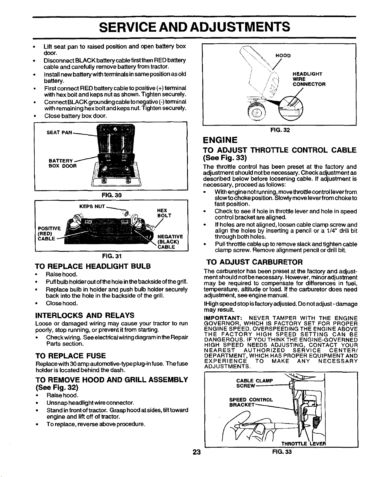
SERVICE AND ADJUSTMENTS
• Lift seat pan to raised position and open battery box
door.
• Disconnect BLACK battery cable first then RED battery
cable and carefully remove battery from tractor.
• Install new battery with terminals in same position as old
battery.
• First connect RED battery cable to positive (+) terminal
with hex bolt and keps nut as shown. Tighten securely.
Connect BLACK grounding cable to negative (-)terminal
with remaining hex bolt and keps nut. Tighten securely.
• Close battery box door.
BATTERY
BOX DOOR
FIG. 30
KEPSNUT\_ HEX
"! ", BOLT
POSITIVE
RED) NEGATIVE
(BLACK)
3ABLE
FIG. 31
TO REPLACE HEADLIGHT BULB
•Raise hood.
•Pullbulbholder out ofthe holeinthebacksideofthegdll.
•Replace bulb in holder and push bulb holder securely
back intothe hole in the backside of the grill.
• Close hood.
INTERLOCKS AND RELAYS
Loose or damaged wiring may cause your tractor to run
poorly, stop running, or prevent itfrom starting.
• Checkwiring. See electricalwiringdiagramintheRepair
Parts section.
TO REPLACE FUSE
Replace with 30 amp automotive-type plug-infuse. The fuse
holder islocated behind the dash.
TO REMOVE HOOD AND GRILL ASSEMBLY
(See Fig. 32)
• Raise hood.
•Unsnap headlight wire connector.
•Stand infrontoftractor. Grasp hoodat sides,tilttoward
engine and lift off of tractor.
•To replace, reverse above procedure.
HOOD
HEADLIGHT
/ / ,:) WIRE
CONNECTOR
FIG. 32
ENGINE
TO ADJUST THRO'n'LE CONTROL CABLE
(See Fig. 33)
The throttle control has been preset at the factory and
adjustment should not be necessary. Check adjustment as
described below before loosening cable. If adjustment is
necessary, proceed as follows:
•With engine notrunning,movethrottlecontrollever from
slow tochoke position.Slowlymove lever from choke to
fast position.
•Check to see if hole in throttlelever and hole in speed
control bracket are aligned.
•If holes are not aligned, loosen cable clamp screw and
align the holes by inserting apencil or a 1/4" ddli bit
through both holes.
•Pull throttle cable up toremove slackand tighten cable
clamp screw. Remove alignment pencil or drill bit.
TO ADJUST CARBURETOR
The carburetor has been preset at the factory and adjust-
ment should not be necessary. However, minor adjustment
may be required to compensate for differences in fuel,
temperature, altitude or load. If the carburetor does need
adjustment, see engine manual.
IHigh speed stop is factory adjusted. DO not adjust - damage
may result.
IMPORTANT: NEVER TAMPER WITH THE ENGINE
GOVERNOR, WHICH IS FACTORY SET FOR PROPER
ENGINE SPEED. OVERSPEEDING THE ENGINE ABOVE
THE FACTORY HIGH SPEED SETTING CAN BE
DANGEROUS. IF YOU THINK THE ENGINE-GOVERNED
HIGH SPEED NEEDS ADJUSTING, CONTACT YOUR
NEAREST AUTHORIZED SERVICE CENTER/
DEPARTMENT, WHICH HAS PROPER EQUIPMENT AND
EXPERIENCE TO MAKE ANY NECESSARY
ADJUSTMENTS.
,.<
CABLE CLAMP
SCREW --
SPEED CONTROL
BRACKET_
THROTTLE LEVER
i
23 FIG. 33
STORAGE
Immediately prepare yourtractor for storageattheend ofthe
season or ifthe tractor willnotbe used for 30 days or more.
CAUTION: Never store the tractor with
gasoline in the tank inside a building
where fumes may reach an open flame
or spark. Allow the engine to cool
before storing In any enclosure,
TRACTOR
Remove mower from tractorfor winterstorage. When mower
is to be stored for a period of time, clean it thoroughly,
remove all dirt, grease, leaves, etc. Store in a clean, dry
area.
•Clean entire tractor (See "CLEANING" inthe Customer
Responsibilities section ofthis manual).
•Inspect and replace belts, if necessary (See belt re-
placement instructionsin theService and Adjustments
section of this manual).
•Lubricate as shown in the Customer Responsibilities
section of this manual.
•Be sure that all nuts, bolts and screws are securely
fastened. Inspect moving parts for damage, breakage
and wear. Replace it necessary.
•Touch up all rusted or chipped paint surfaces; sand
lightlybefore painting.
BATTERY
•Fully charge the battery for storage.
•After a period of time in storage, battery may require
recharging.
•To helppreventcorrosionandpowerleakage dudnglong
pedods of storage, battery cables should be discon-
nected and batterycleaned thoroughly(see'TO CLEAN
BA'I-I'ERY AND TERMINALS" intheCustomer Respon-
sibilities section of this manual).
•After cleaning, leave cables disconnected and place
cables where they cannot come in contactwith batte_
terminals.
•If battery is removed from tractor for storage, do not
store battery directlyon concrete or damp surfaces.
ENGINE
FUEL SYSTEM
IMPORTANT: IT IS IMPORTANT TO PREVENT GUM
DEPOSITS FROM FORMING IN ESSENTIAL FUEL SYSTEM
PARTS SUCH AS CARBURETOR, FUEL FILTER, FUEL
HOSE, OR TANK DURING STORAGE. ALSO,
EXPERIENCE INDICATES THAT ALCOHOL BLENDED
FUELS (CALLED GASOHOL OR USING ETHANOL OR
METHANOL) CAN ATTRACT MOISTURE WHICH LEADS
TO SEPARATION AND FORMATION OF ACIDS DURING
STORAGE. ACIDIC GAS CAN DAMAGE THE FUEL
SYSTEM OF AN ENGINE WHILE IN STORAGE.
•Drain the fuel tank.
•Start the engine and let it run until the fuel lines and
carburetor are empty.
•Never use engine or carburetor cleaner products in the
fuel tank or permanent damage may occur.
•Use fresh fuel next season.
NOTE: Fuel stabilizer is an acceptable alternative in
minimizing the formation offuel gum deposits dudng stor-
age. Add stabilizer to gasoline in fuel tank or storage
container. Always follow the mix ratio found on stabilizer
container. Run engine at least 10 minutes after addir_g
stabilizer to allow thestabilizer to reach the carburetor. Do
not drain the gas tankand carburetor ifusingfuel stabilizer.
ENGINE OIL
Drain oil (withengine warm)and replacewithclean engine oil.
(See "ENGINE" intheCustomer Responsibilities section of
this manual).
CYLINDER(S)
•Remove spark plug(s).
•Pour one ounce of oil through spark plug hole(s) into
cylinder(s).
•Turn ignitionkey to"START' positionfora few seconds
to distribute oil.
•Replace with new sparkplug(s).
OTHER
•Do not store gasoline from one season to another.
•Replace your gasoline can if your can starts to rust.
Rust and/or dirtinyour gasoline willcause problems.
•Ifpossible, storeyourtractorindoorsand cover ittogive
protection from dustand dirt.
•Cover your tractor witha suitable protective cover that
does not retain moisture. Do not use plastic. Plastic
cannot breathe whichallowscondensation to form and
will cause your tractorto rust.
IMPORTANT: NEVER COVER TRACTOR WHILE ENGINE
AND EXHAUST AREAS ARE STILL WARM.
24

TROUBLESHOOTING POINTS
PROBLEM
Will not start
Ha_ _ _a_
Engine will not turn over
Engine clicks but will not
start
Loss of power
Excessive vibration
CAUSE
1. Out of fuel.
2. Engine not =CHOKED" pmpedy.
3. Engine flooded.
4. Bad spark plug.
5. Dirty air filter.
6. Dirty fuel filter.
7. Water in fuel.
8. Loose or damaged wiring.
9. Carburetor out of adjustment.
10. Engine valves out of adjustment.
1. Dirty air filter.
2. Bad spark plug.
3. Weak or dead battery.
4. Dirty fuel filter.
5. Stale or dirty fuel.
6. Loose or damaged widng.
7. Carburetor out of adjustment.
8. Engine valves out of adjustment.
1. Clutch/brake pedal not depressed.
2. Attachment clutch is engaged.
3. Weak or dead battery.
4.- "Blown fuse.
5. Corroded battery terminals,
6. Loose or damaged wiring.
7. Faulty ignition switch.
8. Faulty solenoid or starter.
9. Faulty operator presence switch(es).
1. Weak or dead battery.
2. Corroded battery terminals.
3. Loose or damaged wiring.
4. Faulty solenoid or starter.
1. Cutting too much grass;too fast.
2. Throttle in =CHOKE" position.
3. Build-up of grass, leaves and trash under mower,
4. Dirty air filter.
5. Low oil level/dirty oil.
6. Faulty spark plug.
7. Dirty fuel filter.
8. Stale or dirty fuel.
9. Water in fuel.
10. Spark plug wire loose.
11. Dirty engine air screen/fins.
12. Dirty/clogged muffler,
13. Loose or damaged wiring.
14. Carburetor out of adjustment.
15. Engine valves out of adjustment.
1. Worn, bent or loose blade,
2. Bent blade maedrel.
3. Loose,'dereeged part(s).
CORRECTION
1. Fill fuel tank.
2. See "TO START ENGINE" in Operation section.
3. Wait several minutes before att_mp_ng to start.
4. Replace spark plug.
5. Clean/replace air filter.
6. Replace fuel tilter.
7. Drain fuel tank and carburetor, refill tank with fresh
gasoline and replace fuel filter.
8. Check all wiring.
9. See "To Adjust Carburetor" in Service Adjustments
section.
10. Contact an authorized service center/department.
1. Clean/replace air filter.
2, Replace spark plug.
3. Recharge or replace battery.
4. Replace fuel filter.
5. Drain fuel tank and refill with fresh gasoline.
6. Check all widng.
7. See =To Adjust Carburetor" in Service Adjustments
section.
8. Contact an authorized sewice canter/department.
1. Depress dutch/brake pedal.
2. Disengage attachment dutch.
3. Recharge or replace battery.
4. Replace fuse,
5. Clean battery terminals.
6. Check all wiring.
7. Check/replace ignition switch.
8. Check/replace solenoid or starter.
9. Contact an authorized service center/department.
1. Recharge or replacabattery.
2. Clean batteryterminals.
3. Check all wiring.
4. Check/replaee solenoidor starter.
1. Set in =Higher Cut" position/reduce speed.
2. Adjust throttle control.
3. Clean underside of mower housing.
4. Clean/replace air filter.
5. Check oil leveVchange oil.
6. Clean and regap or change spark plug.
7. Replace fuel filter.
8. Drain fuel tank and refill with fresh gasoline.
9. Drain fuel tank and carburetor, refill tank with fresh
gasoline and replace fuel tilter.
10. Connect and tighten spark plug wire.
11. Clean engine air screen/fins.
12. Clean/replace muffler.
13. Check all widag.
14. See "To Adjust Carburetor" in Service Adjustments
section.
15. Contact an authorized service center/departrnent.
1. Replace blade. Tighten blade bolt.
2. Replace blade mandrel.
3. Tighten loose part(s). Replace damaged parts.
25
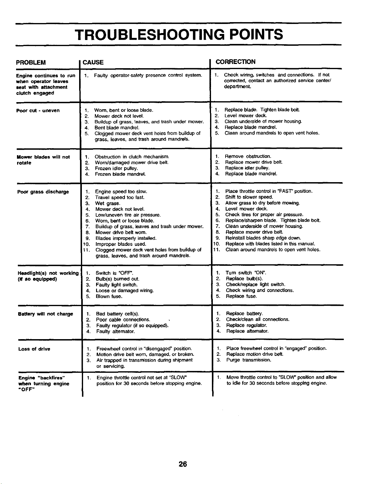
TROUBLESHOOTING POINTS
PROBLEM
Engine continues to run
when operator leaves
seat with attachment
clutch engaged
Poor cut - uneven
Mower blades will not
rotate
poor grass discharge
Headlight(s) not working
(if SO equipped)
Battery will not charge
Loss of drive
Engine "backfires"
when turning engine
=OFF"
CAUSE
1. Faulty operator-safety presence control system.
1, Worn, bent or loose blade.
2. Mower deck not level.
3. Buildup of grass, leaves, and trash under mower.
4. Bent blade mandrel,
5. Clogged mower deck vent hoios from buildup of
grass, leaves, and trash around mandrels.
1. Obstruction in clutch mechanism.
2. Worn/damaged mower drive belt.
3. Frozen idler pulley.
4. Frozen blade mandrel.
1. Engine speed too slow.
2. Travel speed too fast.
3. Wet grass.
4. Mower deck not level.
5. Low/uneven tire air pressure.
6. Worn. bent or loose blade.
7. Buildup of grass, leaves and trash under mower.
8. Mower ddve belt worn.
9. Blades improperly installed.
10. Improper blades used.
lt. Clogged mower deck vent holes from buildup of
grass, leaves, and trash around mandrels.
1. Switch is =OFF".
2. Bulb(s) burned out.
3. Faulty light switch.
4. Loose or damaged widng.
5. Blown fuse.
1. Bad battePJ cell(s).
2. Poor cable connections.
3. Faulty regulator (if so equipped).
4. Faulty altemator.
1. Freewheel control in "disengaged" position.
2. Motion drive belt worn. damaged, or broken.
3. Air trapped in transmission during shipment
or servicing.
t. Engine throttle control not set at "SLOW"
position for 30 seconds before stopping engine.
CORRECTION
1. Check widng, switches and connections. If not
corrected, contact an authoitzed sen/ice center/
department.
1. Replace blade. Tighten blade belt,
2. Level mower deck.
3. Clean underside of mower housing.
4. Replace blade mandrel.
5. Clean around mandrels to open vent holes.
1. Remove obstruction.
2. Replace mower drive belt.
3. Replace idler pulley.
4. Replace blade mandrel,
1. Place throttle control in "FAST" position.
2. Shift to slower speed.
3. Allow grass to dry before mowing.
4. Level mower deck.
5. Check tiros for proper air pressure.
6. Replace/sharpen blade. Tighten blade bolt.
7. Clean underside of mower housing.
8. Replace mower ddve belt.
9. Reinstall blades sharp edge down,
10. Replace with blades listed in this manual
11. Clean around mandrols to open vent holes.
1. Tum switch "ON".
2. Replace bulb(s).
3. Check/replace light switch.
4. Check wiring and connections.
5. Replace fuse.
1. Replace battery,
2. Check/clean all connections.
3. Replace regulator,
4. Replace altemator.
1. Place freewheel control in "engaged" position.
2. Replace motion drive belt.
3. Purge transmission.
1. Move throttle control to "SLOW" position and allow
to idle for 30 seconds before stopping engine.
26
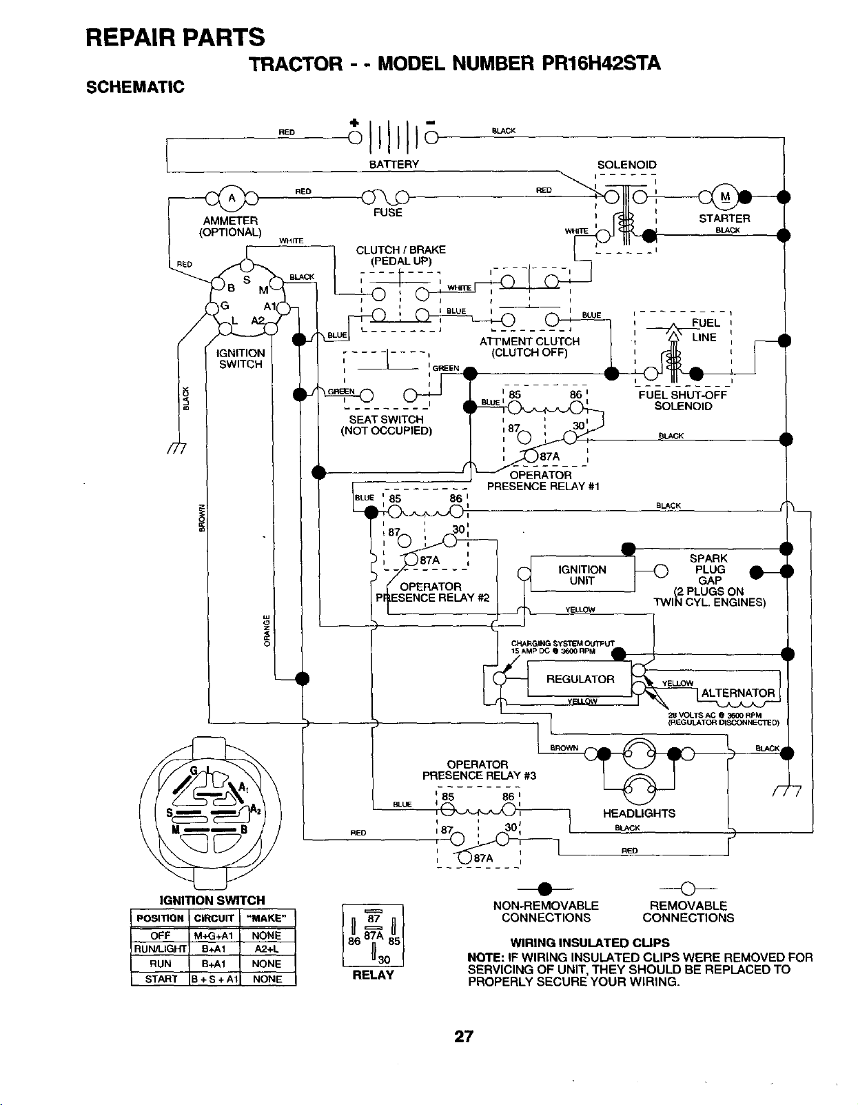
REPAIR PARTS
TRACTOR - - MODEL NUMBER PR16H42STA
SCHEMATIC
BATTERY
FUSE
RE D
)G AI(Z)-
/I I I
i
°
IGNITION SWITCH
POSITION CIRCUIT "MAKE"
OFF M+G+A1 NONE
IRUN!LIGHT B+A1 A2+L
RUN B+A1 NONE
B+S+A1 NONE
RED
SOLENOID
I
B_CK
CLUTCH !BRAKE
(PEDAL UP)
A_MENT CLUTCH
.... -_.... I (CLUTCH OFF)
I I G'REEN • •
I
SEAT SWITCH
(NOT OCCUPIED)
f
BLUE
FUEL SHUT-OFF
SOLENOID
BLACK
BUCK
BLUE
RED
85 86 I
A •
SPARK •
IGNITION--O PLUG
UNIT GAP
(2 PLUGS ON
YELLOW TWIN CYL. ENGINES)
ICHARGING SYSTEM OU3_UT 1
15 AMP DC 03600 RPM
_'_(_ REGULATOR _YELLOW
II I _ALTERNATOR
(REGUL&T(_'_ DISCONNECTED)
OPERATOR _
PRESENCE RELAY #3
i85 86 i
',0_ HEADUGHTS
iij
,87_ i _o', to,.,cK
_ ---<>--
NON-REMOVABLEREMOVABLE
CONNECTIONS CONNECTIONS
START
87
86 85
RELAY
WIRING INSULATED CUPS
NOTE: IF WIRING INSULATED CLIPS WERE REMOVED FOR
SERVICING OF UNIT, THEY SHOULD BE REPLACED TO
PROPERLY SECURE YOUR WIRING.
27
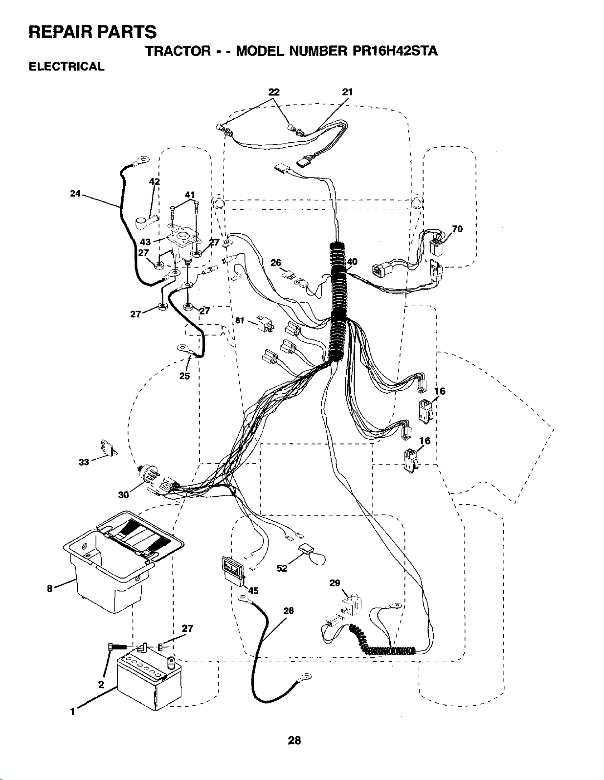
REPAIR PARTS
TRACTOR -- MODEL NUMBER PR16H42STA
ELECTRICAL
i \
iI
42
iI
41
27
22 21
26
I/I
I!j
j i ,70
i/
fl
!
\
I
52
I
I
II
28
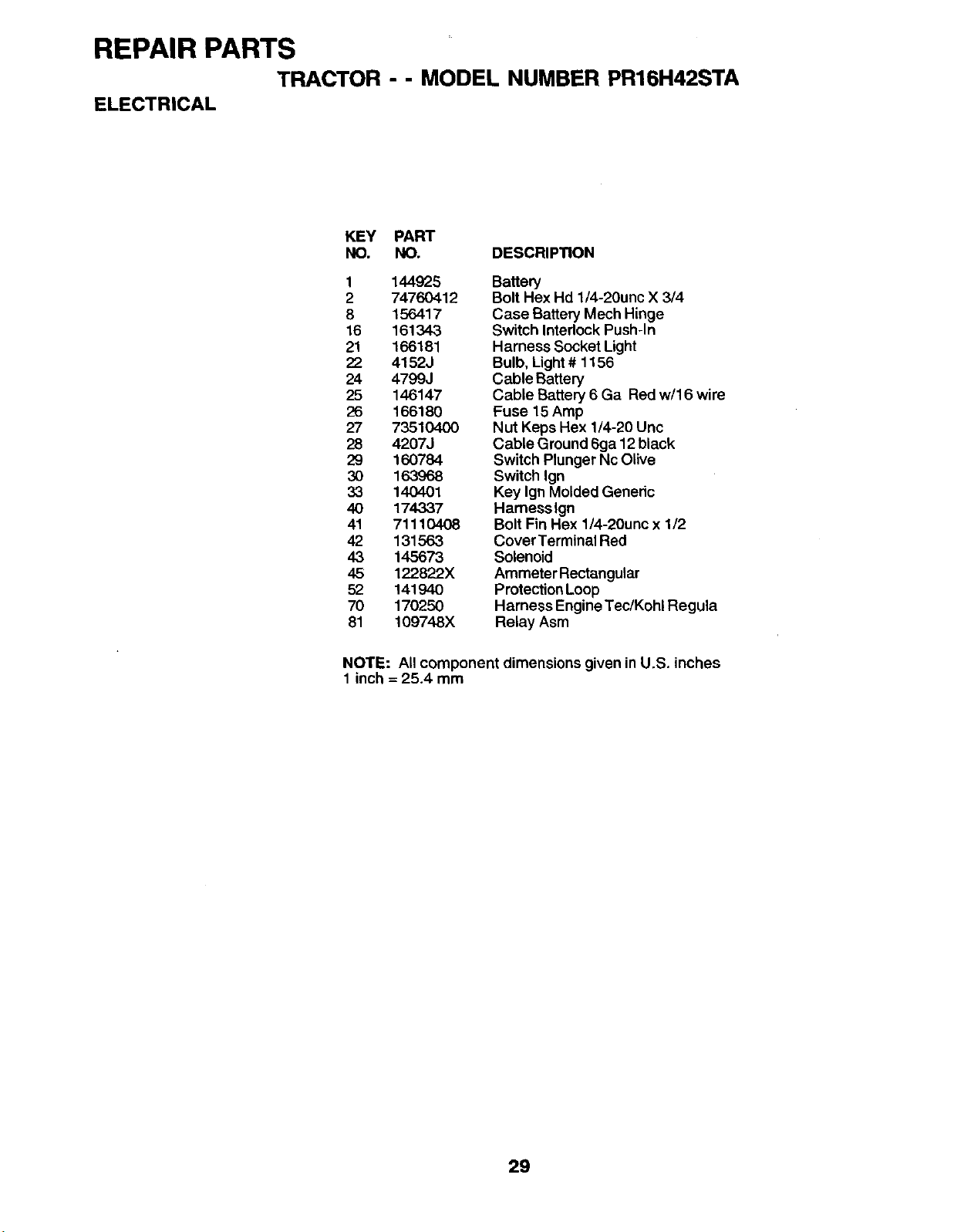
REPAIR PARTS
TRACTOR - -MODEL NUMBER PR16H42STA
ELECTRICAL
KEY PART
NO. NO. DESCRIPTION
1144925
2 74760412
8156417
16 161343
21 166181
22 4152J
24 4799J
25 146147
26 166180
27 73510400
28 42073
29 160784
3O 163968
33 140401
40 174337
41 71110408
42 131563
43 145673
45 122822X
52 141940
70 170250
81 109748X
Battery
Bolt Hex Hd 1/4-20unc X 3/4
Case Battery Mech Hinge
Switch Interlock Push-In
Harness Socket Light
Bulb, Light# 1156
Cable Battery
Cable Battery 6 Ga Red w/16 wire
Fuse 15 Amp
Nut Keps Hex 1/4-20 Uric
Cable Ground 6ga 12 black
Switch Plunger Nc Olive
Switch Ign
Key Ign Molded Generic
Hamesslgn
Bolt Fin Hex 1/4-20unc x 1/2
Cover Terminal Red
Solenoid
Ammeter Rectangular
Protection Loop
Harness Engine Tec/Kohl Regula
Relay Asm
NOTE: All component dimensions given in U.S. inches
1 inch = 25.4 mm
29
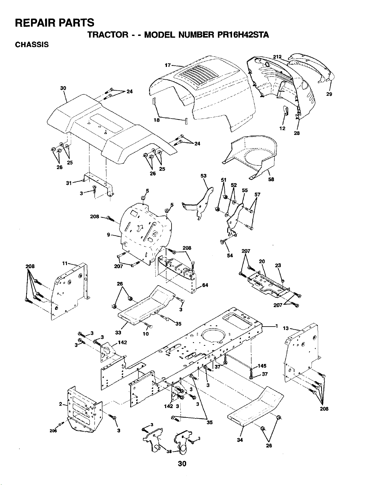
REPAIR PARTS
TRACTOR -- MODEL NUMBER PR16H42STA
CHASSIS
30
i
208
26
5
J
25 53
55 57
12
58
28
29
2O8
26
2O8
54 207
20 23
33 10
142
35
3
38
30
34 26
208
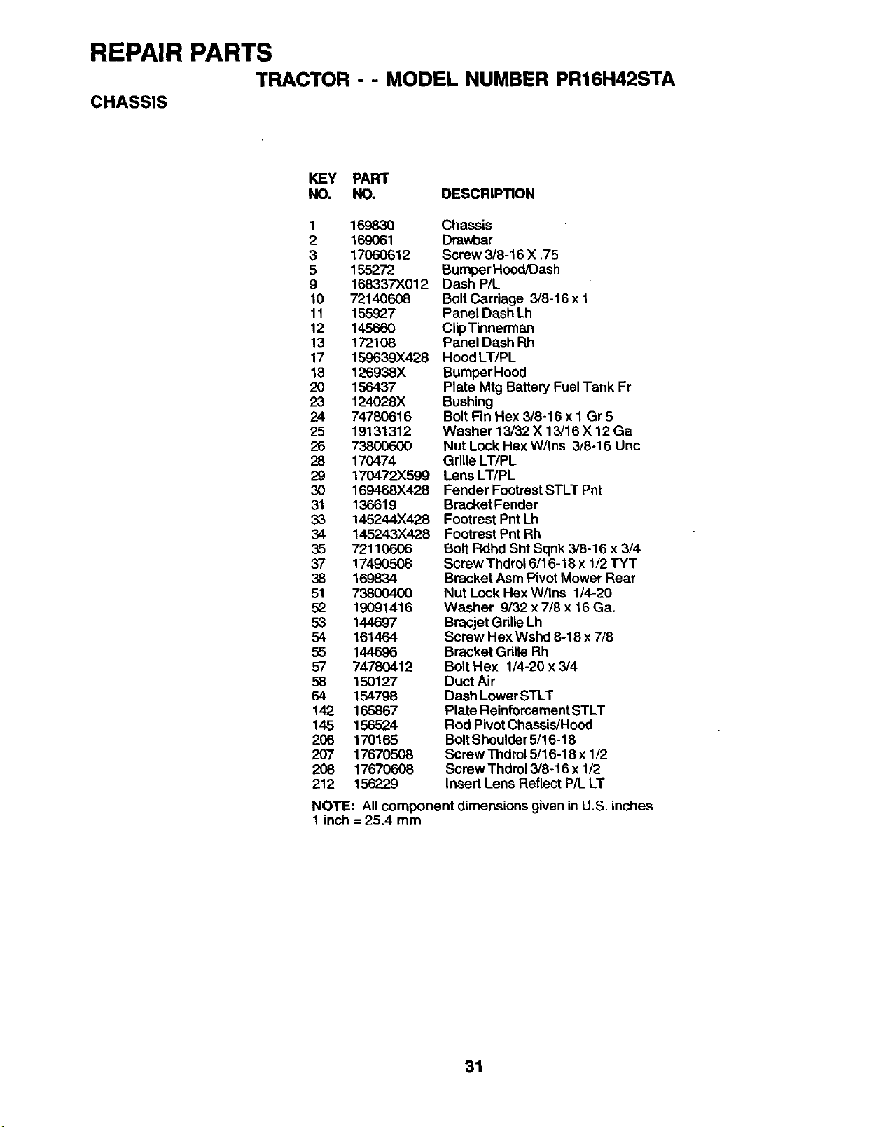
REPAIR PARTS
TRACTOR - - MODEL NUMBER PR16H42STA
CHASSIS
KEY PART
NO. NO. DESCRIPTION
1169830
2169061
3 17060612
5 155272
9168337X012
10 72140608
11 155927
12 145660
13 172108
17 159639)(428
18 126938X
20 156437
23 124028X
24 74780616
25 19131312
26 738006O0
28 170474
29 170472X599
30 169468X428
31 136619
33 145244X428
34 145243X428
35 72110606
37 17490508
38 169834
51 73800400
52 19091416
53 144697
54 161464
55 144696
57 74780412
58 150127
64 154798
142 165867
145 156524
206 170165
207 17670508
208 17670608
212 156229
Chassis
Drawbar
Screw 3/8-16 X .75
Bumper Hood/Dash
Dash P/L
BoltCarriage 3/8-16 x 1
Panel Dash Lh
CiipTinnerman
Panel Dash Rh
Hood LT/PL
BumperHood
Plate Mtg Battery Fuel Tank Fr
Bushing
Bolt Fin Hex 3/8-16 x I Gr 5
Washer 13/32 X 13/16 X 12 Ga
Nut Lock Hex W/Ins 3/8-16 Unc
Gdlle LT/PL
Lens LT/PL
Fender Footrest STLT Pnt
Bracket Fender
Footrest Pnt Lh
Footrest Pnt Rh
Bolt Rdhd Sht Sqnk 3/8-16 x 3/4
Screw Thdrol 6/16-18 x 1/2 TYT
Bracket Asm Pivot Mower Rear
Nut Lock Hex W/ins 1/4-20
Washer 9/32 x 7/8 x 16 Ga.
Bracjet Grille Lh
Screw Hex Wshd 8-18 x 7/8
Bracket Grille Rh
Bolt Hex 1/4-20 x 3/4
Duct Air
Dash Lower STLT
Plate Reinforcement STLT
Rod Pivot Chassis/Hood
Bolt Shoulder 5/16-18
Screw Thdrol 5/16-18 x 1/2
Screw Thdrol 3/8-16 x 1/2
Insert Lens Reflect P/L LT
NOTE: All component dimensions given in U,S. inches
1 inch = 25.4 mm
31
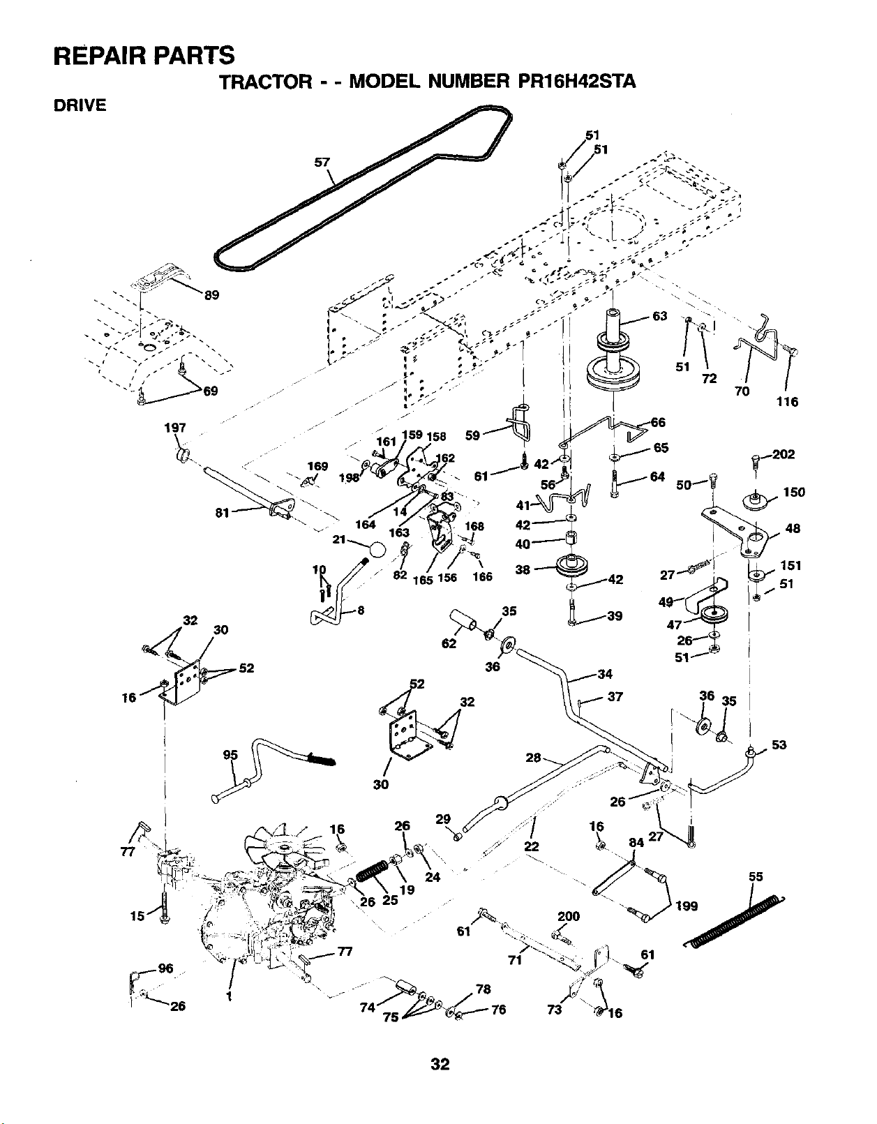
REPAIR PARTS
TRACTOR --MODEL NUMBER PR16H42STA
30
36
151
..36 35
61
32
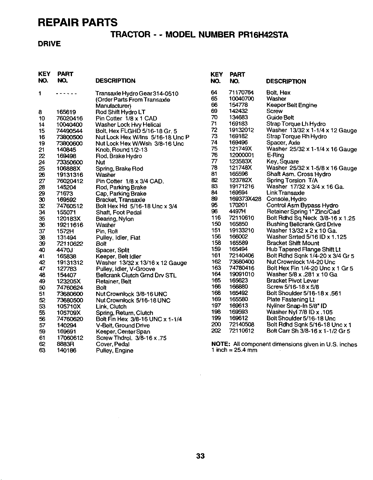
REPAIR PARTS
TRACTOR - -MODEL NUMBER PR16H42STA
DRIVE
KEY PART KEY PART
NO. NO. DESCRIPTION NO. NO. DESCRIPTION
8165619
10 76020416
14 10040400
15 74490544
16 73800500
19 73800600
21 140845
22 169498
24 73350600
25 106888X
26 19131316
27 76020412
28 145204
29 71673
30 169592
32 74760512
34 155071
35 120183X
36 19211616
37 1572H
38 131494
39 72110622
40 4470J
41 165838
42 19131312
47 127783
48 154407
49 123205X
50 74760624
51 73680600
52 73680500
53 105710X
55 105709X
56 74760620
57 140294
59 169691
61 17060612
62 8883R
63 14O186
Transaxle Hydro Gear 314-0510 64 71170764
(Order Parts From Transaxle 65 10040700
Manutacturer) 66 154778
Rod Shift Hydro LT 69 142432
Pin Cotter 1/8 x 1 CAD 70 134683
Washer Lock Flvy Helical 71 169183
Bolt, Hex FLGHD 5/16-18 Gr. 5 72 19132012
Nut Lock Flex W/Ins 5/16-18 Unc P 73 169182
Nut Lock Hex W/Wsh 3/8-16 Unc 74 169496
Knob, Round 1/2-13 75 121749X
Rod, Brake Hydro 76 12000001
Nut 77 123583X
Spring, Brake Rod 78 121748X
Washer 81 165596
Pin Cotter 1/8 x 3/4 CAD. 82 123782X
Rod, Parking Brake 83 19171216
Cap, Parking Brake 84 169594
Bracket, Transaxle 89 169373X428
Bolt Hex Hd 5/16-18 Uric x 3/4 95 170201
Shaft, Foot Pedal 96 449714
Beadng, Nylon 116 72110610
Washer 150 165850
Pin, Roll 151 19133210
Pulley, Idler, Flat 156 166002
Bolt 158 165589
Spacer, Split 159 165494
Keeper, Belt Idler 161 72140406
Washer 13/32 x 13/16 x12 Gauge 162 73680400
Pulley, Idler, V-Groove 163 74780416
Bellcrank Clutch Grnd Drv STL 164 19091010
Retainer, Belt 165 165623
Bolt 166 166880
Nut Crownlock 3/8-16 UNC 168 165492
Nut Cmwnlock 5/16-18 UNC 169 165580
Link, Clutch 197 169613
Spring, Return, Clutch 198 169593
Bolt Fin Hex 3/8-16 UNC x 1-1/4 199 169612
V-Belt, Ground Drive 200 72140508
Keeper, Center Span 202 72110612
ScrewThdrol. 3/8-16 x .75
Cover, Pedal
Pulley, Engine
Bolt, Hex
Washer
Keeper Belt Engine
Screw
Guide Belt
Strap Torque Lh Hydro
Washer 13/32 x 1-1/4 x 12 Gauge
Strap Torque Rh Hydro
Spacer, Axle
Washer 25/32 x 1-1/4 x 16 Gauge
E-Ring
Key, Square
Washer 25/32 x 1-5/8 x 16 Gauge
Shaft Asm. Cross Hydro
Spring Torsion T/A
Washer 17/32 x 3/4 x 16 Ga.
LinkTransaxle
Console, Hydro
Control Asm Bypass Hydro
Retainer Spring 1"Zinc/Cad
Bolt Rdhd Sq Neck 3/8-16 x 1.25
Bushing Bellcrank Grd Drive
Washer 13/32 x 2 x 10 Ga.
Washer Srrted 5/16 ID x 1.125
Bracket Shift Mount
Hub Tapered Flange Shift Lt
Bolt Rdhd Sqnk 1/4-20 x 3/4 Gr 5
Nut Crownlock 1/4-20 Unc
BoltHex Fin 1/4-20 Unc x 1 Gr 5
Washer 5/8 x .281 x 10 Ga
Bracket Pivot Lever
Screw 5/16-18 x 5/8
BoltShoulder 5/16-18 x ,561
Plate Fastening Lt
Nyliner Snap-In 5/8" ID
Washer Nyl 7/8 ID x .105
BoltShoulder 5/16-18 Uric
Bolt Rdhd Sqnk 5/16-18 Unc x 1
BoltCart Sh 3/8-16 x 1-1/2 Gr 5
NOTE: Allcomponent dimensions given in U.S. inches
1 inch = 25.4 mm
33
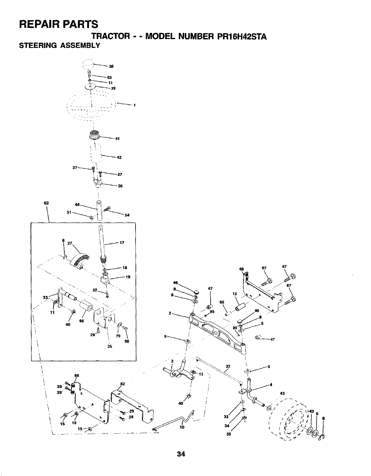
REPAIR PARTS
TRACTOR - - MODEL NUMBER PR16H42STA
STEERING ASSEMBLY
62
8
11
j17
68
29 _82
29"
15
15_._
68 67 67
8_47 .67
10 34
35
34
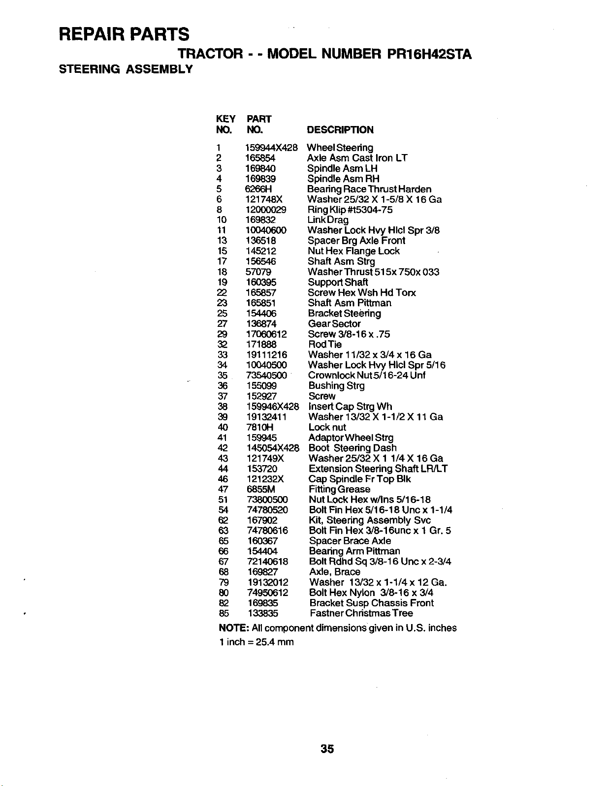
REPAIR PARTS
TRACTOR -- MODEL NUMBER PR16H42STA
STEERING ASSEMBLY
KEY PART
NO. NO, DESCRIPTION
1159944X428
2165854
3169840
4169839
56266H
6 121748X
812OOOO29
10 169832
11 10040600
13 136518
15 145212
17 156546
16 57079
19 160395
22 165857
23 165851
25 1544O6
27 136874
29 17060612
3_ 171888
33 19111216
34 1O04O5OO
35 73540500
36 155O99
37 152927
38 159946X428
39 19132411
40 7810H
41 159945
42 145064X428
43 121749X
44 153720
46 121232X
47 6855M
51 73800500
54 74780520
62 167902
63 74780616
65 160367
66 1544O4
67 72140618
68 169827
79 19132012
80 74950612
82 169835
85 133835
Wheel Steering
Axle Asm Cast Iron LT
Spindle Asm LH
Spindle Asm RH
Bearing Race Thrust Harden
Washer25132 X 1-5/8 X 16 Ga
Ring Klip#t5304-75
LinkDrag
Washer Lock Hvy Hlcl Spr 3/8
Spacer Brg Axle Front
Nut Hex Flange Lock
Shaft Asm Strg
Washer Thrust 515x 750x 033
Support Shaft
Screw Hex Wsh Hd Torx
Shaft Asm Pittman
Bracket Steering
GearSector
Screw 3/8-16 x .75
RodTie
Washer 11/32 x 3/4 x 16 Ga
Washer Lock Hvy Hlcl Spr 5/16
Crownlock NutS/16-24 Unf
Bushing Strg
Screw
Insert Cap Strg Wh
Washer 13/32 X 1-1/2 X 11 Ga
Lock nut
AdaptorWheel Strg
Boot Steering Dash
Washer 25/32 X 1 1/4 X 16 Ga
Extension Steering Shaft LR/LT
Cap Spindle FrTop BIk
FittingGrease
Nut Lock Hex w/Ins 5116-18
Bolt Fin Hex 5/16-18 Unc x 1-1/4
Kit, Steering Assembly Svc
Bolt Fin Hex 3/8-16unc x 1 Gr. 5
Spacer Brace Axle
Bearing Arm Pittman
Bolt Rdhd Sq 3/8-16 Unc x 2-3/4
Axle, Brace
Washer 13/32 x 1-1/4 x 12 Ga.
Bolt Hex Nylon 3/8-16 x3/4
Bracket Susp Chassis Front
Fastner Christmas Tree
NOTE: Allcomponent dimensions given in U.S. inches
1 inch = 25.4 mm
35
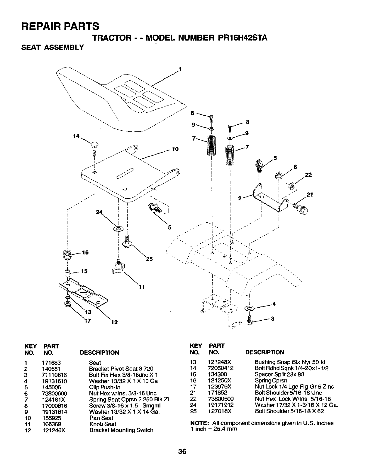
REPAIR PARTS
TRACTOR - - MODEL NUMBER PR16H42STA
SEAT ASSEMBLY
8
5
25
11
p
I
i
)
KEY
NO.
1
2
3
4
5
6
7
8
9
10
11
12
PART
NO.
171683
140551
71110616
1913161O
145O06
7380O6O0
124181X
17000616
19131614
155925
166369
121246X
DESCRIPTION
Seat
Bracket Pivot Seat 8 720
Bolt Fin Hex 3/8-16unc X 1
Washer 13/32 X 1X 10 Ga
Clip Push-In
Nut Hex w/Ins. 3/8-16 Unc
Spring Seat Cprsn 2250 BIk Zi
Screw3/8-16 x 1.5 Smgml
Washer 13/32 X 1X14 Ga.
Pan Seat
Knob Seat
Bracket Mounting Switch
KEY PART
NO, NO. DESCRIPTION
13 121248X
14 72050412
15 134300
16 121250X
17 123976X
21 171852
73800500
24 19171912
25 127018X
Bushing Snap Bik Nyl 50 Id
BoltRdhd Sqnk 1/4-20xl -1/2
Spacer Split28x 88
SpringCprsn
Nut Lock 1/4 Lge Fig Gr 5 Zinc
BoltShoulder 5/16-18 Unc
Nut Hex Lock W/Ins 5/16-18
Washer 17/32 X 1-3/16 X 12 Ga.
BoltShoulder 5/16-18 X 62
NOTE: All component dimensions given in U.S. inches
1 inch = 25.4 mm
36
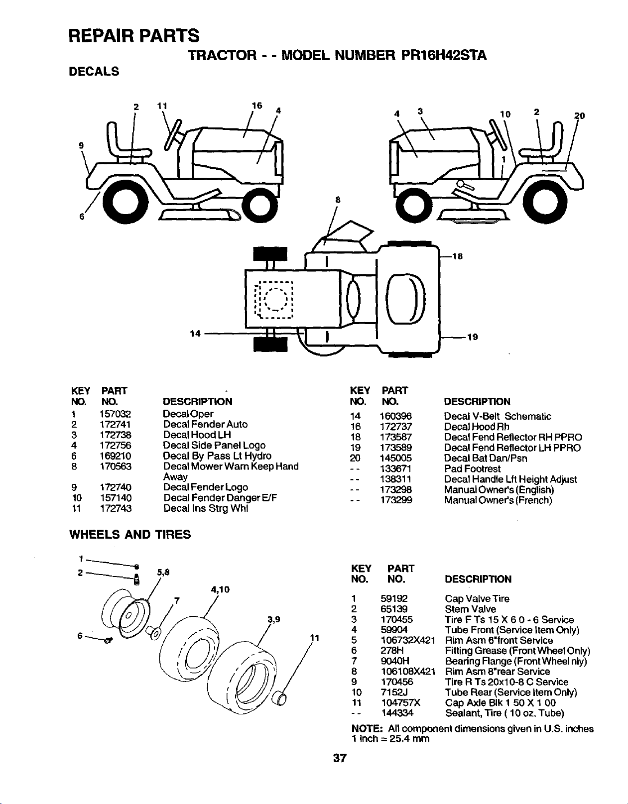
REPAIR PARTS
TRACTOR -- MODEL NUMBER PR16H42STA
DECALS
2 11 16 4 4 3 10 2 20
8
14
KEY PART KEY PART
NO. NO. DESCRIPTION NO. NO.
1 157032 DecaIOper 14 160396
2 172741 Decal Fender Auto 16 172737
3 172738 Decal Hood LH 18 173587
4 172756 Decal Side Panel Logo 19 173589
6 169210 Decal By Pass Lt Hydro 20 145005
8 170563 Decal Mower Warn Keep Hand - - 133671
Away - - 138311
9 172740 Decal Fender Logo -- 173298
10 157140 Decal Fender Danger E/F .- 173299
11 172743 Decal Ins Strg Whl
WHEELS AND TIRES
4,10
11
DESCRIPTION
Decal V-Belt Schematic
Decal Hood Rh
Dec,at Fend Reflector RH PPRO
Decal Fend Reflector LH PPRO
Decal Bat Dan/Psn
Pad Footrest
Decal Handle Lff Height Adjust
Manual Owner's (English)
Manual Owner's (French)
KEY PART
NO. NO. DESCRIPTION
159192
2 65139
3170455
4 59904
5 106732)(421
6 278H
7 9040H
8 106108X421
9170456
10 7152J
11 104757X
-- 144334
Gap Valve Tire
Stem Valve
Tire F Ts 15 X 60-6Serv_e
Tube Front (Service Item Only)
Rim Asm 6"front Service
Fitting Grease (Front Wheel Only)
Bearing Flange (Front Wheel nly)
Rim Asm 6"rear Service
Tire R Ts 20x10-8 C Service
Tube Rear (Service Item Only)
Cap Axle BIk 1 50 X 1 00
Sealant, Tire ( 10 oz. Tube)
NOTE: All component dimensions given in U.S. inches
1 inch = 25.4 mm
37
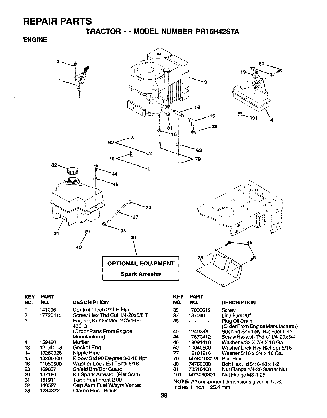
REPAIR PARTS
TRACTOR -- MODEL NUMBER PR16H42STA
ENGINE
33
37
31 /_ 29
4o 1
IOPTIONAL EQUIPMENT
Spark Arrester
8O
KEY
NO.
t
2
3
4
13
14
15
16
23
29
31
32
33
PART
NO.
141296
17720410
159420
12-041-03
13280328
13200300
11050500
169837
13718O
161911
140527
123487X
DESCRIPTION
Control Th/ch 27 LH Flag
Screw Hex Thd Cut 1/4-20x5/8 T
Engine, Kohler Model CV16S-
43513
(Order Parts From Engine
Manufacturer)
Muffler
Gasket Eng
Nipple Pipe
Elbow Std 90 Degree 3/8-18 Npt
Washer Lock Ext Tooth 5/16
Shield Bm/Dbr Guard
Kit Spark Arrestor (Flat Scrn)
Tank Fuel Front 200
Cap Asm Fuel W/sym Vented
Clamp Hose Black 38
KEY PART
NO. NO.
35 17000612
37 137040
38
4O 124028X
44 17670412
46 19091416
62 10040500
77 19101216
79 M740108025
80 74760508
81 73510400
101 M73030800
DESCRIPTION
Screw
Line Fuel 20"
Plug Oil Drain
(Order FromEngineManufacturer)
Bushing Snap Nyl BIk Fuel Line
Screw Hexwsh Thdrol 1/4-20x3/4
Washer 9/32 X 7/8 X 16 Ga
Washer Lock Hvy HlclSpr 5/16
Washer 5/16 x 3/4 x 16 Ga.
Bolt Hex
BoltHex Hd 5/16-18 x 1/2
Nut Flange 1/4-20 Starter Nut
Nut Flange M8-1.25
NOTE: All component dimensions given in U. S.
inches 1 inch =25,4 mm
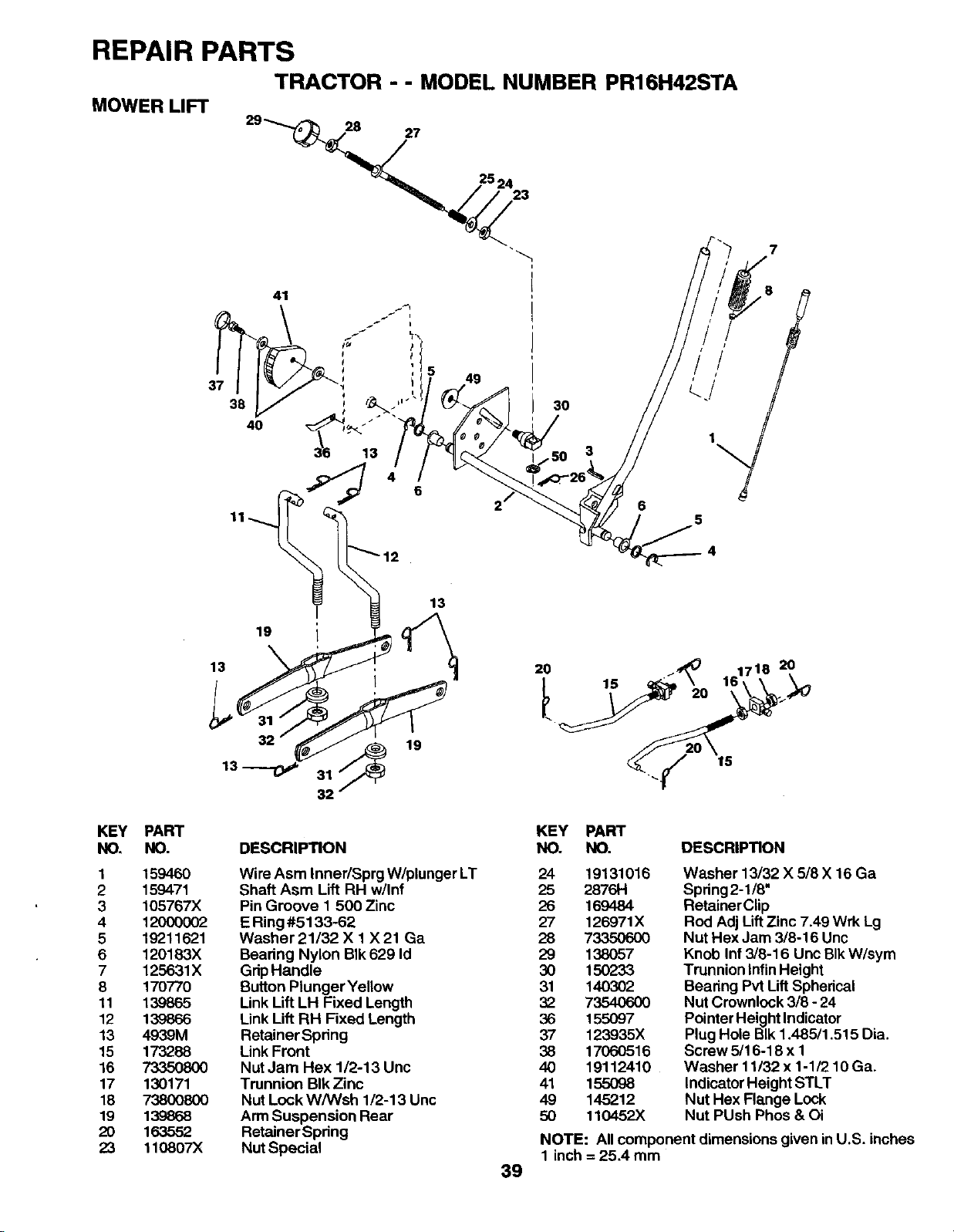
REPAIR PARTS
MOWER LIFT TRACTOR --MODEL NUMBER PR16H42STA
3O
65
4
KEY
NO.
1
2
3
4
5
6
7
8
11
12
13
15
16
17
18
19
20
23
13
PART
NO.
15946O
159471
105767X
12OO0O02
19211621
120183X
125631X
170770
139865
139866
4939M
173288
7335O8OO
130171
738OO8O0
139868
163552
110807X
13
I
19 I
19
32
DESCRIPTION
Wire Asm Inner/Sprg W/plunger LT
Shaft Asm Lift RH w/Inf
Pin Groove 1 500 Zinc
E Ring #5133-62
Washer 21/32 X 1 X 21 Ga
Bearing Nylon BIk 629 Id
Grip Handle
Button Plunger Yellow
Link Lift LH Fixed Length
Link Lift RH Fixed Length
Retainer Spdn9
Link Front
Nut Jam Hex 1/2-13 Unc
Trunnion BIk Zinc
Nut Lock W/Wsh 1/2-13 Unc
Arm Suspension Rear
Retainer Spring
Nut Special
20
39
KEY PART
NO. NO. DESCRIPTION
24 19131016
25 2876H
26 169484
27 126971X
28 7335O6O0
29 138057
30 150233
31 140302
32 73540600
36 155097
37 123935X
38 17060516
40 19112410
41 155098
49 145212
50 t 10452X
Washer 13/32 X 5/8 X16 Ga
Spring2-1/6"
Retainer Clip
Rod Adj Lift Zinc 7.49 Wrk Lg
Nut Hex Jam 3/8-16 Unc
Knob Inf 3/8-16 Unc BIk W/sym
Trunnion Infin Height
Bearing Pvt Uft Spherical
Nut Crownlock 3/8 - 24
Pointer Height Indicator
Plug Hole BIk 1.485/1.515 Dia.
Screw 5/16-18 x 1
Washer 11/32 x 1-1/2 10 Ga.
Indicator Height STLT
Nut Hex Flange Lock
Nut PUsh Phos & Oi
NOTE: Allcomponent dimensions given in U.S. inches
1 inch = 25,4 mm
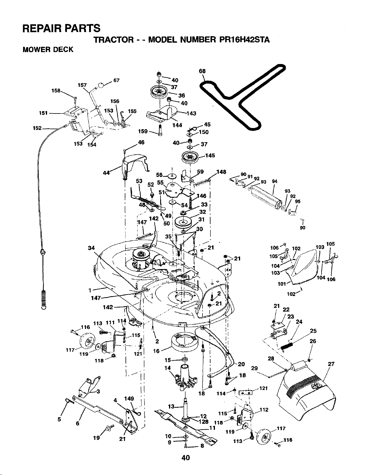
REPAIR PARTS
TRACTOR -- MODEL NUMBER PR16H42STA
MOWER DECK
157
153 154
156
155
,146
i
34
56
4
21
\2
16
14
\
10-,--_
g_
28
29
.18
_121
18 114_ !
lol \
lO2_
21 22
_23 24
\
117
103 105
25
26
27
40
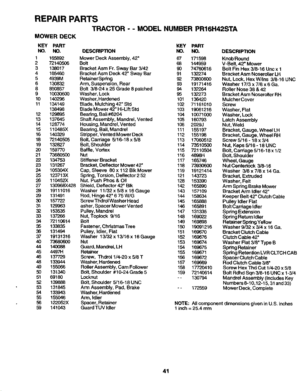
REPAIR PARTS
TRACTOR - - MODEL NUMBER PR16H42STA
MOWER DECK
KEY PART KEY PART
NO. NO. DESCRIPTION NO. NO.
1 165892 Mower Deck Assembly, 42" 67 171598
2 72140506 Bolt 68 144959
3 138017 Bracket Asm Fr. Sway Bar 3/42 90 74760616
4165460 Bracket Asm Deck 42" Sway Bar 91 132274
5 4939M RetainerSpdng 92 73800600
6 130832 Arm, Suspension, Rear 93 19171416
8 850857 Bolt 3/8-24 x25 Grade 8patched 94 132264
9 10030600 Washer, Lock 95 132273
10 140296 Washer, Hardened 101 136420
11 134149 Blade, Mulching 42" Std 102 71161010
138498 Blade Mower 42" Hi-Uft Std 103 19061216
12 129895 Beadng, Ball #6204 104 10071000
13 137645 Shaft Assembly, Mandrel, Vented 105 160793
14 128774 Housing, Mandrel,Vented 106 2029J
15 110485X Bearing, Ball, Mandrel 111 155197
16 140329 Stripper, Vented Mower Deck 112 155196
18 72140505 Bolt, Carriage 5/16-18 x 5/8 113 17060512
19 132827 Bolt, Shoulder 114 73510500
20 159770 Baffle, Vortex 115 72110504
21 7368O5O0 Nut 116 4898H
22 134753 Stiffener Bracket 117 165746
23 131267 Bracket, Deflector Mower42" 118 73930600
24 105304X Cap, Sleeve 80 x 112 BIk Mower 119 19121414
25 123713X Spring, Torsion, Deflector 2 52 121 143723
26 110452X Nut, Push Phos & Oil 128 153390
27 130968X428 Shield, Deflector42" BIk 142 165890
28 19111016 Washer 11/32 x 5/8 x 16 Gauge 143 157109
29 131491 Rod, Hinge 42" 6 75 WIG 144 158634
30 157722 Screw Thdrol Washer Head 145 165888
31 129963 asher, Spacer Mower Vented 146 165891
32 153535 Pulley, Mandrel 147 131335
33 137266 Nut, Toplock 9/16 148 169022
34 72110614 Bolt 149 169898
35 133835 Fastener, Christmas Tree 150 19091216
36 131494 Pulley, Idler, Fiat 151 169670
37 19131316 Washer 13/32 x 13/16 x 16 Gauge 152 169676
40 73680600 Nut 153 169674
44 140088 Guard, Mandrel, LH 154 169675
45 44971-1 Retainer 155 169671
46 137729 Screw, Thdrol 1/4-20 x 5/8 T 156 169672
48 133944 Washer, Hardened 157 169669
49 155066 Roller Assembly, Cam Follower 158 17720410
50 131340 Bolt, Shoulder #10-24Grade5 159 72140614
51 69180 Locknut - - 130794
52 139888 Bolt, Shoulder 5/16-18 UNC
53 131845 Arm Assembly, Pad, Brake - - 172559
54 133943 Washer, Hardened
55 155046 Arm, Idler
56 122052X Spacer, Retainer
59 141043 Guard TUV Idler
DESCRIPTION
Knob Round
V-Belt, 42" Mower
Bolt Fin Hex 3/8-16 Unc x 1
Bracket Asm Noseroller LH
Nut, Lock, Hex W/Ins 3/8-16 UNC
Washer 17/3 x 7/8 x 6 Ga.
Roller Nose 38 & 42
Bracket Asm Noseroller RH
Mulcher Cover
Screw
Washer, Flat
Washer, Lock
Latch Assembly
Nut, Weld
Bracket, Gauge, Wheel LH
Bracket, Gauge, Wheel RH
Screw 5/16 - 18 x 3/4
Nut, Keps 5/16 - 18 UNC
Bolt, Carriage 5/16-18 x 1/2
Bolt, Shoulder
Wheel, Gauge
Nut Centedock 3/8-16
Washer 3/8 x 7/8 x 14 Ga.
Bracket, Extruded
Washer, Felt
Arm Spring Brake Mower
Bracket Arm Idler 42"
Keeper Belt 42" Clutch Cable
Pulley Idler Flat
BoltCarriage Idler
Spring Extension
Spring Return Idler
Retainer Spring Yellow
Washer 9/32 x 3/4 x 16 Ga.
Bracket Clutch Cable
Clutch Cable 42"
Washer Flat 3/8" Type B
Spring Retainer
Spdng Retention LVR CLTCH CAB
Spacer Clutch Cable
Rod Clutch Cable 3/8"
Screw Hex Thd Cut 1/4-20 x 5/8
Bolt Rdhd Sqn 3/8-16 UNC x 1-3/4
Mandrel Assembly (IncludesKey
Numbers 8-10,12-15, 31 and 33)
Mower Deck, Complete
NOTE: All component dimensions given in U.S. inches
1 inch = 25.4 mm
41
LIMITED WARRANTY
The Manufacturer warrants to the odginal consumer purchaser that this product as manufactured is free from defects in
materials and workmanship. For a pedod of two (2) years from date of purchaee by the odginal consumer purchaser, we will
repair or replace, at our option, without charge for parts or labor incurred in replacing parts, any part which we find to be
defective due to materials or workmanship. This Warranty is subject to the following limitations and exclusions.
1. This warranty does not apply to the engine, other than FHP manufactured traneexle/transmission components, battery
(except as noted below) or components parts thereof. Please refer to the applicable manufacturer's warranty on these
items.
2. Transportation charges for the movement of any power equipment unit or attachment are the responsibility of the
purchaser. Transportation charges for any parts submitted for replacement under this warranty must be paid by the
purchaser unless such return is requested by Frigidaire Home Products.
3. Battery Warranty: On products equipped with a Battery, we will replace, without charge to you, any battery which we find
to be defective in manufacture, during the first ninety (90) days of ownership. After ninety (90) days, we will exchange
the Battery, charging you 1/12 of the price of a new Battery for each full month from the date of the original sale. Battery
must be maintained in accordance with the instructions furnished.
4. The Warranty period for any products used for rental or commercial purposes is limited to 90 days from the date of
original purchase.
5. This Warranty applies only to products which have been propedy assembled, adjusted, operated, and maintained in
accordance with the instructions furnished. This Warranty does not apply to any product which has been subjected to
alteration, misuse, abuse, improper assembly or installation, delivery damage, or to normal wear of the product.
6. Exclusions: Excluded from this Warranty are belts, blades, blade adapters, normal wear, normal adjustments, standard
hardware and normal maintenance.
7. In the event you have a claim under this Warranty, you must return the product to an authorized service dealer.
Should you have any unanswered questions concerning this Warranty, please contact:
Fdgidaire Home Products
Outdoor Products Customer Service Dept.
250 Bobby Jones Expressway
Augusta, GA 30909 USA
In Canada contact:
Fdgidaire Home Products
7075 Ordan Drive
Mississauga, Ontario
L5T 1K6
giving the model number, sedal number and date of purchase of your product and the name and address of the authorized
dealer from whom it was purchased.
THIS WARRANTY DOES NOT APPLY TO INCIDENTAL OR CONSEQUENTIAL DAMAGES AND ANY IMPLIED WARRAN-
TIES ARE LIMITED TO THE SAME TIME PERIODS STATED HEREIN FOR OUR EXPRESSED WARRANTIES. Some areas
do not allow the limitation of consequential damages or limitations of how long an implied Warranty may last, so the above
limitations or exclusions may not apply to you. This Warranty gives you specific legal dghts, and you may have other dghts
which vary from locale to locale.
This is a limited Warranty within the meaning of that term as defined in the Magnuson-Moss Act of 1975.
42

SUGGESTED GUIDE FOR SIGHTING SLOPES FOR SAFE OPERATION
J_
ONLY RIDE UP AND DOWN HILL,
NOT ACROSS HILL
SIGHT AND HOLD THIS LEVEL WITH
SKY LINE OR TREE.
!_ Operate your Tractor up and down the face of slopes (not I
I
greater than 15°), never across the face. Make turns gradu- I
ally to prevent tipping or loss of control. Exercise extreme
caution when changing direction on slopes.
PARTS AND SERVICE
Your POULAN PRO product has been expertly engineered and carefully manufactured to rigid quality standards. As
with all mechanical products, some adjustments or part replacement may be necessary during the life of your unit.
FOR SERVICE OR REPLACEMENT PARTS:
1. Consult your dealer/place of purchase.
2. Consult the yellow pages of your phone directory for the name of the nearest service dealer (under "saws" for Chain
Saws or under "lawn mowers" for Trimmers, Brusbcutter_ and Blowers).
3. For replacement parts, have available the following information:
a. Model Number/Manufacturer's I.D. Number.
b. Description ofpart.
NOTE: Frigidaire Home Products provides parts and service through its authorized distributors and dealers;
therefore, all requests for parts and service should be directed to your local dealer(s). The philosophy of
Frigidaire Home Products is to continually improve all of its products. If the operating characteristics or
the appearance of your product differs from those described in this Manual, please contact your local local
dealer for updated information and assistance.