"MPORTANT MANUAL
OWNER'S
MANUAL
MODEL NO.
536.886531
Caution:
Read and Follow
All Safety Rules
and Instructions
Before Operating
This Equipment
DO NOT THROW AWAY
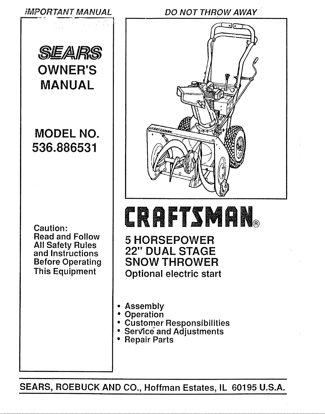
5 HORSEPOWER
22" DUAL STAGE
SNOW THROWER
Optional electric start
®
• Assembly
• Operation
• Customer Responsibilities
° Servlc_ and Adjustments
• Repair Parts
,,=,=,,=,,= ,=,
SEARS, ROEBUCK AND CO., Hoffman Estates, IL 60195 U.S.A.
= 11 11 11 ,=H ,,,,HH= ,H 111 11,11,1=,==,=H= 11 1111
SAFETY RULES
_ CAUTION. ALWAYS DISCONNECT SPARK PLUG WIRE AND _li
PLACE WIRE WHERE IT CANNOT CONTACT SPARK PLUG
TQ PREVENT ACCIDENTAL STARTING WHEN SETTING-UP,
TRANSPORTING, ADJUSTING OR MAKING REPAIRS,
IMPORTANT
SAFETY STANDARDS REQUIRE OPERATOR PRESENCE CONTROLS TO MINIMIZE THE
RISK OF INJURY. YOUR SNOW THROWER IS EQUIPPED WITH SUCH CONTROLS. DO NOT
ATTEMPT TO DEFEAT THE FUNCTION OF THE OPERATOR PRESENCE CONTROL UNDER
ANY CIRCUMSTANCES.
TRAINING
1. Read the operator's manual carefully. Be
thoroughly familiar with the controls and the
proper use of the snow thrower. Know how to
stop the snow thrower and disengage the
controls quickly.
2. Never allow children to operate the snow thrower
and keep them away while it is operating. Never
allow adults to operate the snow thrower without
proper instruction. Do not carry passengers.
3. Keep the area of operation clear of all persons,
particularly small children, and pets_
4. Exercise caution to avoid slipping or falling,
especially when operating in reverse.
PREPARATION
1. Thoroughly inspect the area where the snow
thrower is to be used and remove all doormats,
sleds, boards, wires, and other foreign objects.
2. Disengage all clutches and shift into neutral
before starting the engine (motor).
3. Do not operate the snow thrower without wearing
adequate winter outer garments° Wear footwear
that will improve footing on slippery surfaces,
4, Handle fuel with care; it is highly flammable.
(a) Use an approved fuel container.
(b) Never remove fuel tank cap or add fuel to a
running engine or hot engine.
(c) Fill fuel tank outdoors with extreme care.
Never fill fuel tank indoors.
,
(d) Replace fuel tank cap securely and wipe up
spilled fuel.
(e) Never store fuel or snow thrower with fuel in
thetank insideof abuilding where fumes may
reach an open flame or spark.
(f) Check fuel supply before each use, allowing
space for expansion as the heat of the engine
(motor) and/or sun can cause fuelto expand.
Use extension cords and receptacles as specified
by the manufacturer for all snow throwers with
electric drive motors or electric starting motors
6_ Adjust the snow thrower height to clear gravel or
crushed rock surfaces.
7o Never attempt to make any adjustments while the
engine (motor) is running (except when
specifically recommended by the manufacturer).
8, Let engine (motor) and snow thrower adjust to
outdoor temperatures before starting to clear
snow.
9. Always wear safety glasses or eye shields during
operation or while performing an adjustment or
repair to protect eyes from foreign objects that
may be thrown from the snow thrower.
OPERATION
1. Do not put hands or feet near or under rotating
parts° Keep clear of the discharge opening at all
times,,
2. Exercise extreme caution when operating on or
crossing gravel drives, walks, or roads. Stay alert
for hidden hazards or traffic.
3. After striking a foreign object, stop the engine
(motor), remove the wire from the spark plug,
disconnect the cord on electric motors,
thoroughly inspect the snow thrower for any
damage, and repair the damage before restarting
and operating the snow thrower.
4, If the snow thrower should start to vibrate
abnormally, stop the (motor) and check
immediately forthe cause_ Vibration is generally
a warning of trouble°
5. Stop the engine (motor) whenever you leave the
operating position, before unclogging the auger/
impeller housing or discharge guide, and when
making any repairs, adjustments, or inspections.
When cleaning, repairing, or inspecting, make
certain the auger/impeller and all moving parts
have stopped. Disconnect the spark plug wire
and keep the wire away from the plug to prevent
accidental starting°
7 Take all possible precautions when leaving the
snow thrower unattended. Disengage the auger/
impeller, shift to neutral, stop engine, and
remove key.

SAFETY RULES
8. Do not runthe engine indoors, except when starting
the engine and for transporting the snow thrower in
or out of the building. Open the outside doors;
exhaust lumesaredangerous (containing CARBON
MONOXIDE, an ODORLESS and DEADLY GAS).
9. Do not clear snow across the face of slopes.
Exercise caution when changing direction on
slopes. Do not attempt to clear steep slopes.
10. Never operate the snow thrower without proper
guards, plates or other safety protective devices
in place.
11. Never operate the snow thrower near glass
enclosures, automobiles, window wells,
drop-oils, and the like without properadjustment
of the snow discharge angle. Keep children and
pets away.
12. Do not overload the machine capacity by
attempting to clear snow at too fast a rate.
13o Never operate the snowthrower at high transport
speeds on slippery surfaces. Look behind and
use care when backing°
t4. Never direct discharge at bystanders or allow
anyone in tront of the snow thrower.
15. Disengage power to the auger/impeller when
snow thrower is transported or not in use.
16. Useonly attachments and accessories approved
by the manufacturer of the snow thrower (such
as tire chains, electric start kits, etc.).
17. Never operate the snow thrower without good
visibility or light. Always be sure of your footing,
and keep a firm hold on the handles. Walk; never
rug.
CAUTION: STOP THE
ENGINE BEFORE
UNCLOGGING
%DISCHARGE CHUTE.Lj
MAINTENANCE AND STORAGE
1. Check shear bolts and other bolts at frequent
improper tightness to be sure the snow thrower
is in safe working condition.
2. Never store the snow throwerwith fuel inthe fuel
tank inside a building where ignition sources are
present such as hot water and space heaters,
clothes dryers, and the like. Allow the engine to
cool before storing in any enclosure.
3. Always refer to operator's manual instructions
for important details if the snow thrower isto be
stored for an extended period°
4. Maintain or replace safety and instruction labels,
as necessary.
5o Run the snow thrower a few minutes after
throwing snow to prevent freeze-up of the auger/
impelter_
WARNING ...................
This snow thrower is for use on sidewalks,
driveways, and other ground level surfaces.
CAUTION should be exercised while using on
steep sloping surfaces. DO NOT USE SNOW
THROWER ON SURFACES ABOVE GROUND
LEVEL such as roofs of residences, garages,
porches or other such structures or buildings,
.................. ,,, i Hl,ll,ll,,,
I _ LOOK FOR THIS SYMBOL TO POINT OUT
! A IMPORTANT SAFETY PRECAUTIONS. IT
!,_ MEANS--ATTENTION!!! BECOMEALERT!!!
,..===., YOUR SAFETY IS INVOLVED.
• ................................... i iiiii
,=
CONGRATULATIONS on your purchase of a Sears
Craftsman Snow Thrower It has been designed, engi-
neered and manufactured to give you tfTebest possible
dependability and performance
Should you experience any problem you cannot easily
remedy, please contact your nearest Sears Service
Center/Department Sears has competent, well-trained
technicians and the proper tools to service or repair this
unit
Ptease read and retain this manual The instructions will
enable you to assemble and maintain your snow thrower
properly, Always observe the "SAFETY RULES,"
H i iHl,, ,,Hn
MODEL
NUMBER 536 886531
SERIAL
NUMBER
DATE OF'--_
PURCHASE
THE MODELAND SERtAL NUMBERS WILL BE
FOUND ON A DECAL ATTACHED TO THE REAR
OF THE SNOW THROWER HOUSING
YOU SHOULD RECORD BOTH SERIAL NUMBER
AND DATE OF PURCHASE AND KEEP tNASAFE
PLACE FOR FUTURE REFERENCE
MAINTENANCE AGREEMENT
A Sears Maintenance Agreement is available on this
product Contact your nearest Sears Store for details
PRODUCT SPECIFICATIONS
u,,,, ,, i,iH ,,,, i, i , u, ,,H,,, , i,,,,H, ,,H,
HORSE POWER: 5 hp
DISPLACEMENT: 12.04
cu. in.
GASOLINE CAPACITY: 2 quarts
Unleaded
HH, IIII1,1 H I ,,,, ,.
OIL (21 oz. Capacity): SAE 5W-30
SPARK PLUG : Champion
(GAP .030 in.) RJ19LM
HHn,HH H IHHH nil,,,
VALVE CLEARANCE: Intake: .010 In.
Exhaust: .010 In_
i Hm,H,, I " I'
CUSTOMER RESPONSIBILITIES
• Read and observe the safety rules
• Follow a regular schedule in maintaining, caring for and using your snow thrower
a FolIow the instructions under "Customer Responsibilities" and "Storage" sections of this owner's manual,,
HH, H,,' ......................... , HHH H',,' ! nHHH I H, HI HHHn" I,"l
TWO YEAR LIMITED WARRANTY ON CRAFTSMAN
SNOW THROWER
For two years from the date of purchase, when this Craftsman Snow Thrower is maintained, lubricated
and luned_up according to the instructions in the owner's manual, Sears will repair, free of charge, any
defect in material and workmanship
tf this Craftsman Snow Thrower is used for commercial or rental purposes, this warranty applies for only
90 days from the date of purchase
This warranty does not cover the following:
* Expendable items which become worn during normal use, such as spark plugs, drive belts and shear
pins
* Repairs necessary because of operator abuse or negligence, including bent crankshafts and the failure
to maintain the equipment according to the instructions contained in the owner's manual
WARRANTY SERVICE IS AVAILABLE BY RETURNING THE CRAFTSMAN SNOW THROWER TO THE
NEAREST SEARS SERVICE CENTER/DEPARTMENT IN THE UNITED STATES TH1S WARRANTY
APPLIES ONLY WHILE THIS PRODUCT IS IN USE tN THE UNITED STATES
This warranty gives you specific legal rights, and you may also have other rights which may vary from
state to state
SEARS, ROEBUCK AND CO Deparlment 731CR-W, Hoflman Estates, IL 60195
........................................ , i,, HH I , HHH, HI H I
4
TABLE OF CONTENTS
SAFETY RULES ................................................2,3
PRODUCT SPECIFICATIONS ...............................4
CUSTOMER RESPONSIBILITIES ......4,15,16
WARRANTY ......................................................... 4
TABLE OF CONTENTS .......................................5
INDEX .........................................................................5
ASSEMBLY .........................................................6-9
OPERATION .................. ................................... t 0-14
SERVICE AND ADJUSTMENTS ........... 17-23
STO RAG E ..............................................................24
SERVICE RECOMMENDATIONS .....................25
TROUBLE SHOOTING .................................... 26
REPAIR PARTS (SNOW TH ROWER)co. 28-37
REPAIR PARTS (ENGINE) ................................38-42
PARTS ORDERINGISERVlCE ........Back Cover
INDEX
A
Adjustment:
Belt ...................................................18,19
Bell Guide ...........................................20
Cable ...........................................................18
Carburetor ...........................................13,22
Friction Wheel ....................................20,2t
Spark Plug .................................................23
Traction and Auger .................... 18,19
Assembly:
Crank Assembly ............................................ 8
Shifter Lever ....................................................9
Skid Height Adjustment ..................7, 17
Unpacking ....................................... 7
B
Belts:
Adjust Belts ........................ 18,19
Belt Guide Adjustment ............ 20
Replace Belts ............................... 19
C
Cables, Clutch ......................... 7, 9, 18
Carburetor: ........................................13,24
Choke ............................ 10, 11, 13
Clutch, Levers ........................... 10, 11
Controls:
Engine ............................ 10, 11, t3, t4
Snow Thrower ............................ 10
Crank:
Adjusting Rod ...................... 8, 17
Assembly ........................................... 8
Operation ................................... 11
Customer Respo nsibilities .........4,15,16
Agreement .................................. 4
Auger Gear Box .................... 16
Auger Shaft .................................. 15
Engine ........................................ 16
General Recommendations ........ 15
Hex Shaft and Gears .................... 16
D
Drive, Auger ............................. 11
Drive, Traction ......................... 11
Deflector, Snow Chute .................. 1t
E
Engine:
Conlrol .......................... t0, 1t, 13, 14
Oil Cap ....................... t2, 16
Oil Change .......................... 16
Oil Level ...................... 12, 16
Oil Type .......................... 4, 12, 16
Speed Governor ............... 24
Starting, Manually ................. 13
Storage .................................... 24
F
Fuel, Type ............................. 4, 12
Fuel, Storage .......................................12, 24
Friction Wheel:
Adjustment ........................................ 20
Replacement ................................. 21
G
Gears:
Auger Gear Box ............................... 16
Hex Shaft .............................................16
H
Handle, Upper and Lower ..........................7
Height Adjust Skids ...............................7, 17
Hex Shaft .........................................................t 6
i
Ignition, Key .................. 10, 11,13, 14
Index .......................... 5
L
Levers:
Auger Drive Clutch ........7, 10, 11, 18
Choke ...................... 10, 11,13, 14
Shifter ................................... 9, 10, 11
ThrOttle Control ........... 10, l 1,13, t 4
Traction Drive Clutch .... 7, 10, 11, 18
Lubrication:
Auger Gear Box .......................... 18
Auger Shaft ................... 15
Chart .................................... 25
Disc Drive Plate ......................... 15
Engine ................................. t2,!6,24
Flex Shaft and Gears ................ 16
O
Oi!:
Engine .....................................4, 12, 16
Extreme Cold Weather .............. 12,16
Storage ....................................... 24
Type ....................... 4, I2, I6
Operation:
Carburetor .................. 13
Engine Controls .......... 10, 11, !3,14
Operating 9now Thrower 11, 12, 15
Lockout Pin, Wheel ................... 12
Operating Tips ...................... 14
Starting the Engine, Recoil ........ 13
Snow Thrower Controls ......... 10-12
P
Parts .............................. 28-42
Primer Bulton ........... 10, 1t, 13
R
Repair/Replacement Parts ...... 28-42
Recoil Starter .......................... 13
Replacements:
Auger Shear Boil ...............................22
Belts ............................................. 18,19
Friction Wheel ..............................20,21
S
Safety Rules .........................................2, 3
Service and Adjustments:
Auger Housing Height .............. 7, 17
Auger Shear Bolt ............................. 22
Belts ........................................... 18-19
Belt Guide ......................................... 20
Belt Replacements .............................19
Cable ...................................... 7, 9, 18
Carburetor ............................ 13,22, 24
Friction Wheel ................. 20, 2t
Spark Plug ................................... 23
Service Recommendations ............ 24
Spark Plug ................................. 16, 23
Specifications ......................... 4
Speed Governor .......................... 22
Starting the Engine:
Recoil Start ........................................ 13
Stopping the Engine ................ 13, ! 4
Stopping the Snow Thrower ............. 11
Shipping Carton .............................. 6, 7
Skid Height .................................. 17
Shifter Lever ......................... 9-11
Shear Bolts ....................... 22
Storage ................................ 24
T
Table of Contents ......................... 5
Trouble Shooting Chart .................... 26
Tools for Assembly .......................... 6
Traction Drive Belt ................. 18, I9
Tire Pressure ..................... 17
W
Warranty ..................................... 4
Wheel, Lockout Pin ........ !2
ASSE LY
.,?,ONTENTS OF SHIPPING CARTON TOOLS REQUIRED FOR ASSEMBLY
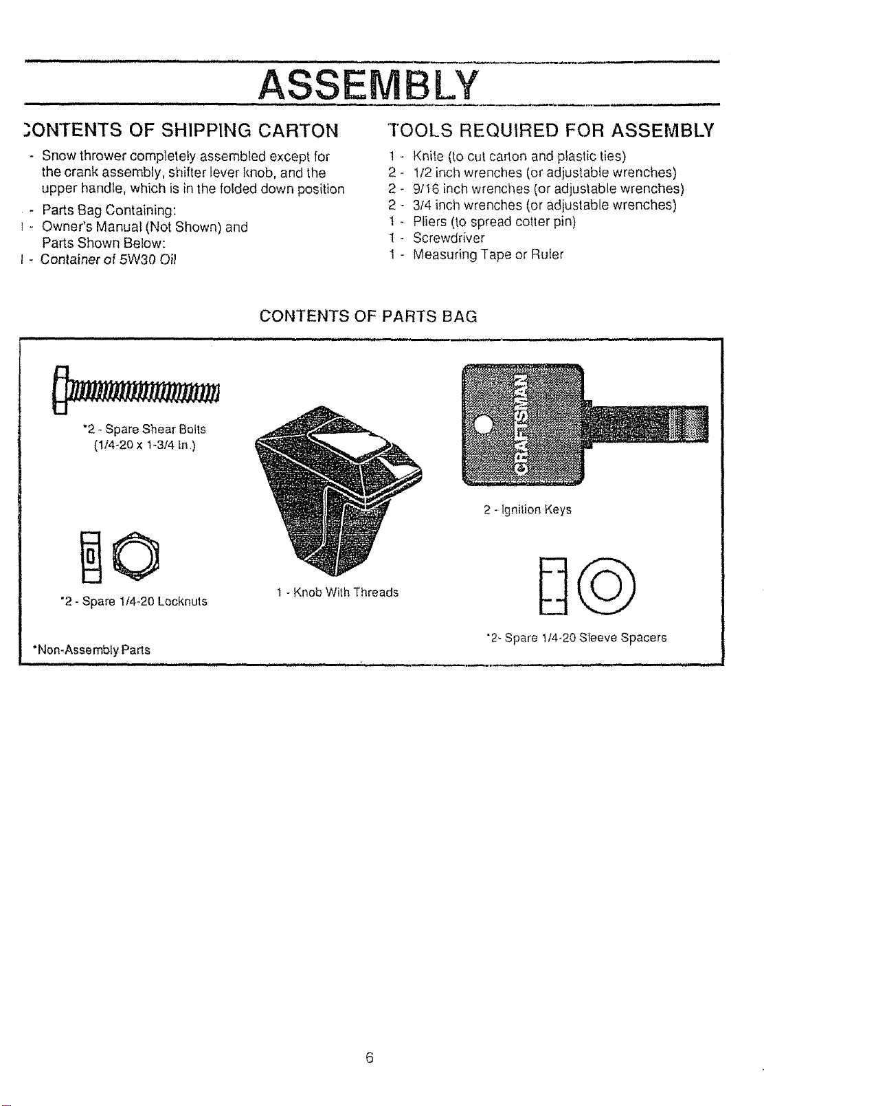
- Snow thrower complelely assembled except for t
the crank assembly, smiter lever knob, and the 2
upper handle, which is in the folded down position 2
- Parts Bag Containing: 2
- Owner's Manual (Not Shown) and 1
Parts Shown Below: 1
- Conlainer of 5W30 Oil 1
Kniie (to cut cadon and plastic ties)
1/2 inch wrenches (or adjustable wrenches)
9/16 inch wrenches (or adjustable wrenches)
3/4 inch wrenches (or adjustable wrenches)
Pliers (to spread cotter pin)
Screwdriver
Measuring Tape or Ruler
CONTENTS OF PARTS BAG
*2 - Spare Shear Bolts
(1t4-20 x t-3/4 tn)
"2- Spare 1t4-20 Lecknuts
1 - Knob With Threads
"Non-Assembly Parts
nn n,u,,, H,u m,,,,,, i, , i ,,,,,,,,,,iu ' , ,, ,i .
2 - ignition Keys
"2-Spare t14-20Sleeve Spacers
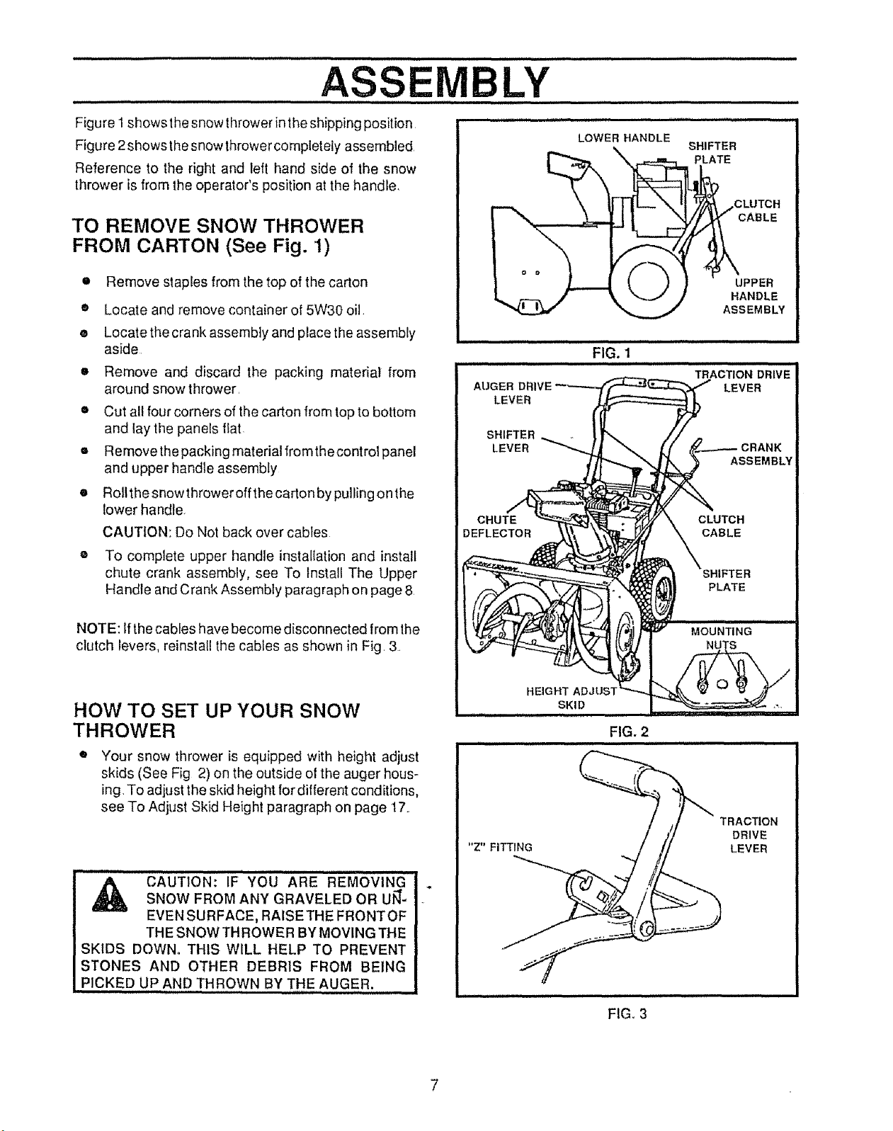
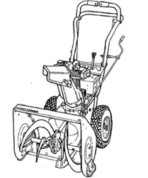
Figure1showsthesnowthrower intheshipping position
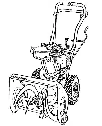
Figure 2shows thesnow thrower completely assembled
Reference to the right and left hand side of the snow
thrower is from the operator's position at the handle.
TO REMOVE SNOW THROWER
FROM CARTON (See Fig. 1)
• Remove staples from the top of the carton
• Locate and remove container of 5W30 oil.
• Locatethe crank assembly and place the assembly
aside
o Remove and discard the packing material from
around snow thrower
o Cut all four corners of the carton from top to bottom
and lay the panels flat
= Remove the packing material fromthe control panel
and upper handle assembly
• Rollthe snowthrower off the carton by pulling onthe
lower handle+
CAUTION: Do Not back over cables
® To complete upper handle instaltation and install
chute crank assembly, see To Install The Upper
Handle and Crank Assembty paragraph on page 8
ii iin,,
FIG. 1
CABLE
UPPER
HANDLE
ASSEMBLY
NOTE: If the cables have become disconnected from lhe
clutch levers, reinstall the cabfes as shown in Fig, 3.
HOW TO SET UP YOUR SNOW
THROWER
Your snow thrower is equipped with height adjust
skids (See Fig 2) on the outside ot the auger hous-
ing. To adjust the skid height for different conditions,
see To Adjust Skk:l Height paragraph on page 17+.
" CAUTION: IF'YO'U'"'ARE 'R'E'r_0VING
SNOW FROM ANY GRAVELED OR UJ_-
EVEN SURFACE, RAISETHE FRONTOF
THE SNOW TH ROWER BY MOVING THE
SKIDS DOWN+ THIS WILL HELP TO PREVENT
STONES AND OTHER DEBRIS FROM BEING
PICKED UP AND THROWN BY THE AUGER.
"Z" FITTING
FIG. 2
TRACTION
DRIVE
LEVER
7
ASSEMBLY
,,,, ,,,, - ,,,,,,, ,,,,
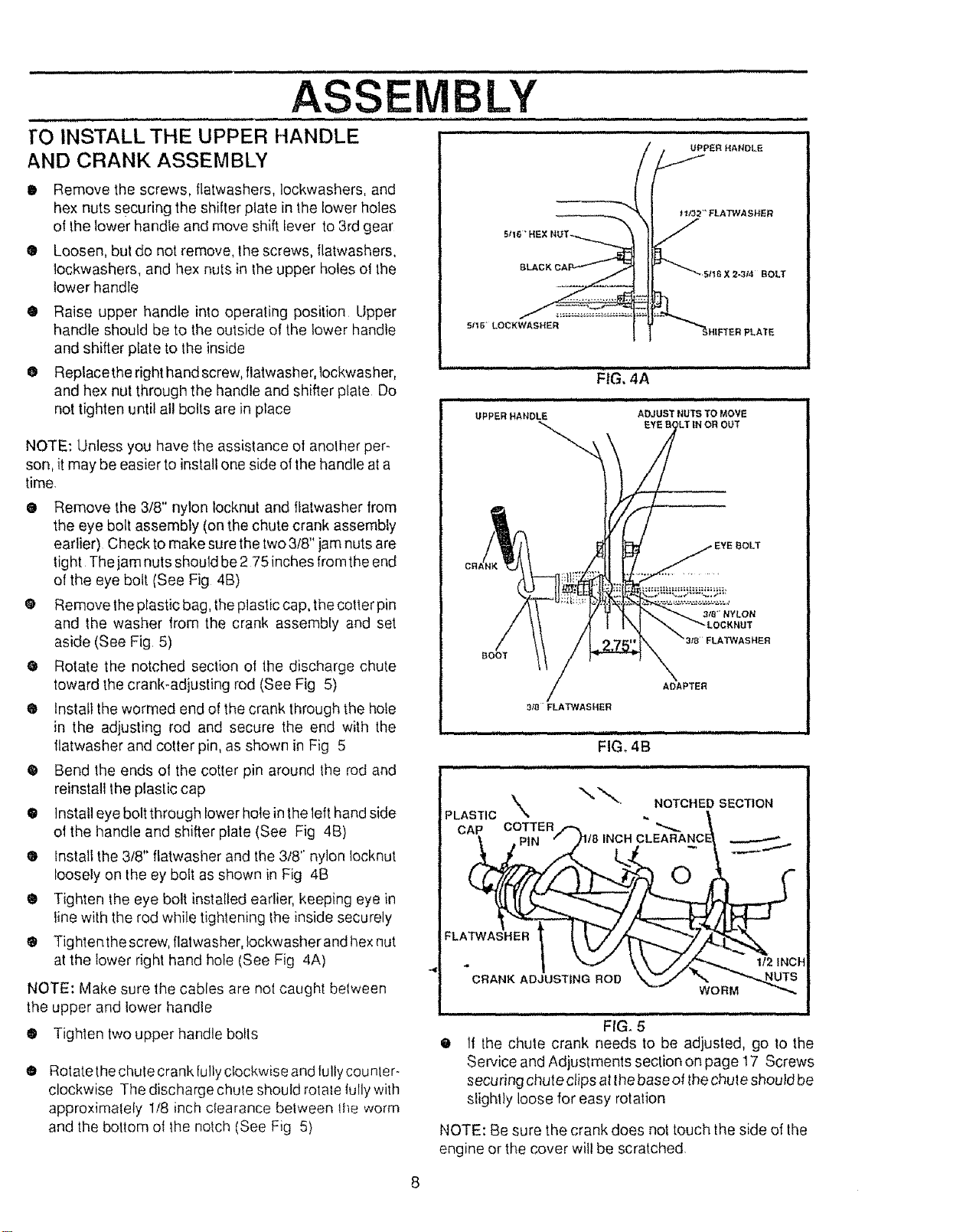
rO INSTALL THE UPPER HANDLE
AND CRANK ASSEMBLY
• Remove the screws, flatwashers, lockwashers, and
hex nuts securing the shitter plate in the lower holes
of the lower handle and move shift lever to 3rd gear
® Loosen, but do not remove, the screws, flatwashers,
lockwashers, and hex nuts in _heupper holes ol the
lower handle
® Raise upper handle into operating position Upper
handle should be to the outside of the lower handle
and shifter prate to the inside
O Replacethe right hand screw, flatwasher, lockwasher,
and hex nut through the handle and shifter plate Do
not tighten t_ntilall bolts are in place
NOTE: Unless you have the assistance of another per-
son, it may be easier to install one side ot the handle ata
time.
@ Remove the 3/8" nylon locknut and flatwasher from
the eye bolt assembly (on the chute crank assembly
earlier) Check to make sure thetwo 3/8" jam nuts are
tight The jam nuts should be 2 75 inches from the end
of the eye bolt (See Fig 4B)
@ Remove the plastic bag, the plastic cap, the cotter pin
and the washer from the crank assembly and set
aside (See Fig 5)
@ Rotate the notched section of the discharge chute
toward the crank-adjusting rod (See Fig 5)
® Install the wormed end of the crank through the hofe
in the adjusting rod and secure the end with the
llatwasher and cotter pin, as shown in Fig 5
• Bend the ends of the cotter pin around the rod and
reinstall the plastic cap
@ Instal] eye bolt through lower hole in the left hand side
ot the handle and shifter plate (See Fig 4B)
® tnstall the 3/8" flatwasher and the 3/8" nylon locknut
loosely on the ey bolt as shown in Fig 4B
® Tighten the eye bolt installed earlier, keeping eye in
line with the rod while tightening the inside securely
® Tightenthe screw, flalwasher, Iockwasherand hex nut
at the lower right hand hole (See Fig 4A)
NOTE: Make sure the cables are not caught between
the upper and lower handle
O Tighten two upper handle bolts
O
Rotate the chute crank fully clockwise and lulty counler-
clockwise The discharge chule should rotale tully with
approximately 1/8 inch ctearance belween ihe worm
and the bottom ot the notch (See Fig 5)
FTER PLATE
BOOT
FLATWASHER
3_FLATWASHER
ADAPTER
i i i,,,,, n, ,nil n,,i,ii nnl
FIG, 4B
PLASTIC
CAP COTTER/-
FLA_.
)118 INCH
CRANK ADJUSTING ROD
NOTCHED SECTION
;LEARANC_
@
....................
If the chute crank needs to be adjusted, go to the
Service and Adjustments section on page 17 Screws
securing chute clips atthe base of thechule should be
slight}y loose for easy rotation
NOTE: Be sure the crank does not touch the side of the
engine or the cover wilt be scratched,
...............ASSEMBLY ...............
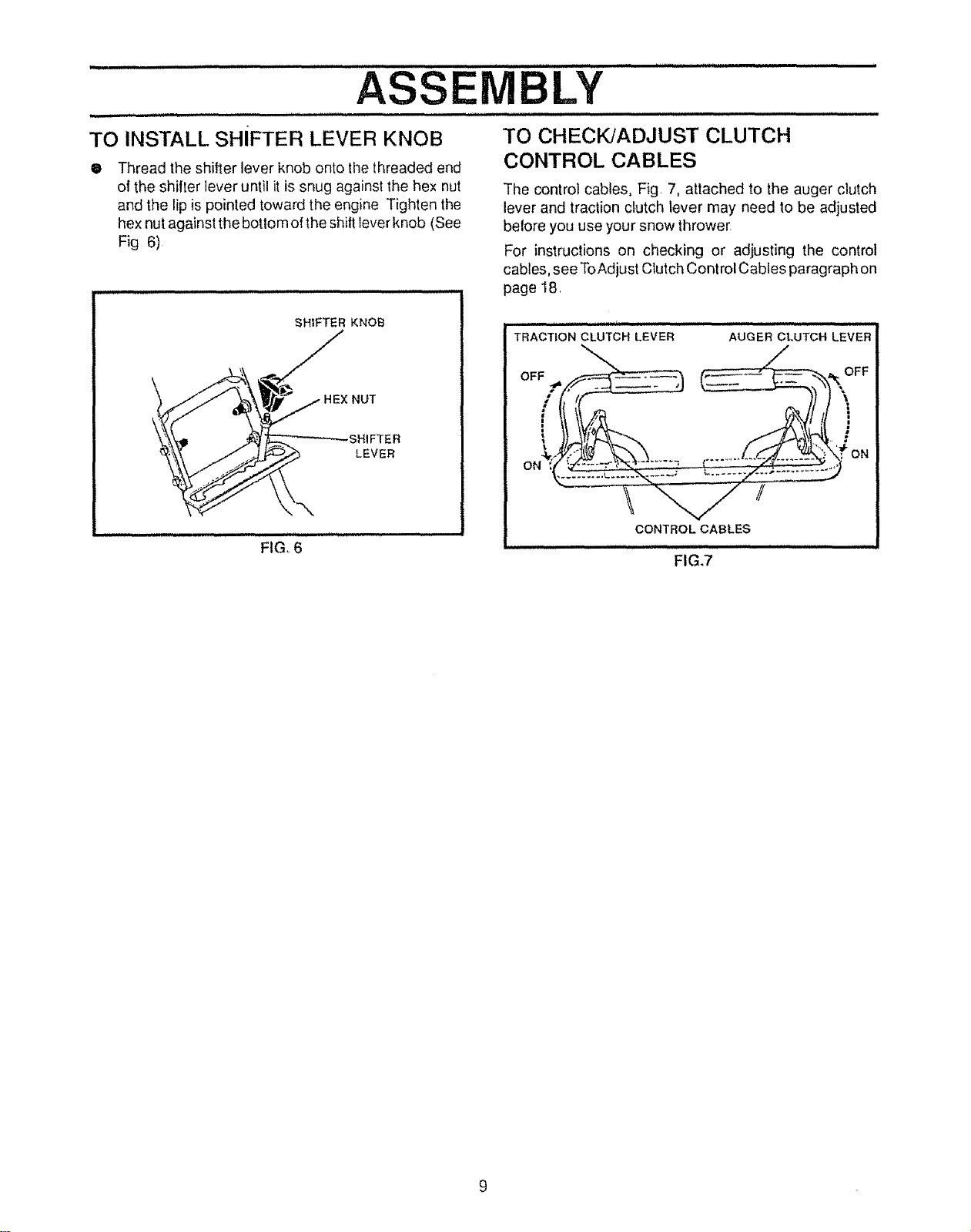
TO INSTALL SHIFTER LEVER KNOB
• Thread the shifter lever knob onto the threaded end
ol the shilter lever until it is snug against the hex nut
and the lip is pointed toward the engine Tighten the
hex nut against the botlom o! the shift lever knob (See
Fig 6)
TO CHECKJADJUST CLUTCH
CONTROL CABLES
The control cables, Fig. 7, attached to the auger clutch
lever and traction clutch lever may need to be adjusted
belore you use your snow thrower
For instructions on checking or adjusting the control
cables, see ToAdjust Clutch Control Cables paragraph on
page 18
SHIFTER KNOB
""_"_'\ __H EX N UT
HEX
_._. LEVER
F,GI'6"'
TRACTION CLUTCH LEVER AUGER CLUTCH LEVER
OFF __ FF
I I,ft- _ ]] ]
, .......... ON
CONTROL CABLES
FIG.7
.................. r , HHH'""t' ''"""1' __" ..... ' '"""L.......... -
OPERATION
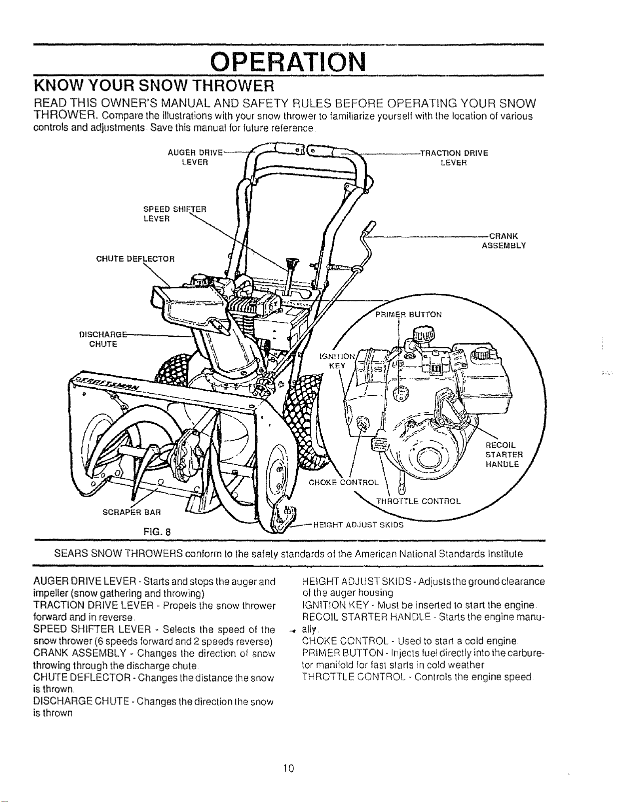
KNOW YOUR SNOW THROWER
READ THIS OWNER'S MANUAL AND SAFETY RULES BEFORE OPERATING YOUR SNOW
THROWER. Compare the illustrations with your snow thrower to tamiliarize yourself with the location of various
controls and adjustments Save this manual for luture reference
AUGER -TRACTION DRIVE
LEVER LEVER
SPEED SHIFTER
LEVER
CHUTE DEFLECTOR
_CRANK
ASSEMBLY
_BUTTON
CHUTE
SCRAPER BAR
FIG. 8
n l m,un,,, ,nil,,, ,U,,,H , nH ,,H,',,,',' , ,.,P..
SEARS SNOW THROWERS conform to the safety standards of the American National Standards Institute
AUGER DRIVE LEVER- Starts and stops the auger and
impeller (snow gathering and throwing)
TRACTION DRIVE LEVER - Propels the snow thrower
forward and in reverse,
SPEED SHIFTER LEVER - Selects the speed of the
snow thrower (6 speeds forward and 2 speeds reverse)
CRANK ASSEMBLY - Changes the direction of snow
throwing through the discharge chute
CHUTE DEFLECTOR- Changes the distance the snow
is thrown
DISCHARGE CHUTE. Changes the direction the snow
is thrown
HEIGHT ADJUST SKIDS- Adjusts the ground clearance
of the auger housing
IGN1TION KEY - Must be inserted to start the engine
RECOIL STARTER HANDLE - Starts the engine manu-
--. alI_
CHOKE CONTROL - Used to start a cold engine
PRIMER BUTTON- Injects luel directly into the carbure-
tor manilotd for last slarts in cold weather
THROTTLE CONTROL - Controls the engine speed
10
OPERATION
u J,,J i
The operation ot any snow thrower can result in foreign objects being thrown into the
eyes, which can result in severe eye damage Always wear safety glasses or eye
shields while operating the snow thrower
We recommend standard safety glasses available at SEARS Retail or Catalog
Stores or a wide vision safety mask !or over your glasses
iii i i, ,1,,1, ,,,,,i , t
HOW TO USE YOUR SNOW
THROWER
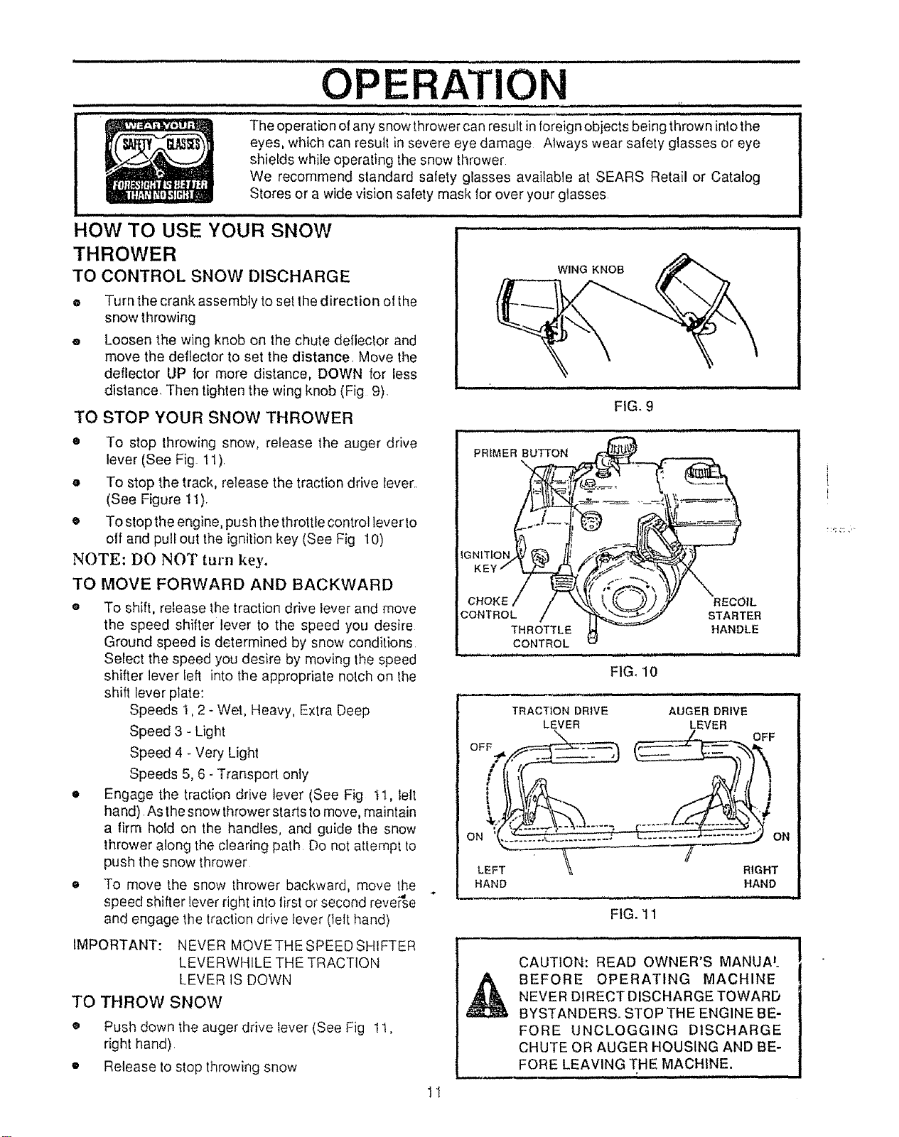
TO CONTROL SNOW DISCHARGE
® Turn the crank assemMy to set the direction ol the
snow throwing
® Loosen the wing knob on the chute deflector and
move the deflector to set the distance. Move the
deflector UP for more distance, DOWN for less
distance. Then tighten the wing knob (Fig 9)
TO STOP YOUR SNOW THROWER
WING KNOB
FIG_ 9
• To stop throwing snow, release the auger drive
lever (See Fig. 11)
o To stop the track, release the traction drive Iever.
(See Figure 11).
• To stop the engine, push the throttle control lever to
off and pull out the ignition key (See Fig 10)
NOTE: DO NOT turn key.
TO MOVE FORWARD AND BACKWARD
o To shift, release the traction drive lever and move
the speed shifter lever to the speed you desire
Ground speed is determined by snow conditions
Select the speed you desire by moving the speed
shifter lever left into the appropriate nolch on the
shift lever plate:
Speeds 1,2 - Wet, Heavy, Extra Deep
Speed 3 - Light
Speed 4 - Very Light
Speeds 5, 6- Transport only
• Engage the traction drive lever (See Fig I1, lelt
ha nd) As the snow thrower starts to move, maintain
a firm hold on the handles, and guide the snow
thrower along the clearing path Do not attempt to
push the snow thrower
e To move the snow thrower backward, move the
-,d
speed shifter lever right into first or second reverse
and engage the traction drive lever (left hand)
IMPORTANT: NEVER MOVETHESPEEDSHfFTER
LEVERWHILE THE TRACTION
LEVER IS DOWN
TO THROW SNOW
• Push down the auger drive lever (See Fig 1I,
right hand)
• Release to stop throwing snow
FIG, 10
TRACTION DRIVE
LEVER
,,,q,,, 1,1,, ,
AUGER DRIVE
_EVER
OFF
ON
LEFT RIGHT
HAND HAND
FIG. 11
CAUTION: READ OWNER'S MANIJA'.
BEFORE OPERATING MACHINE
NEVER DIRECT DISCHARGE TOWARD
BYSTANDERS. STOP THE ENGINE BE-
FORE UNCLOGGING DISCHARGE
CHUTE OR AUGER HOUSING AND BE-
FORE LEAVING THE MACHINE°
- ,m ,,,, , , ,, i , ,, i I,H,,H, I I I
1I
OPERATION
ii ....,i i i,,,,.11 Wl...,, i. ,iJ
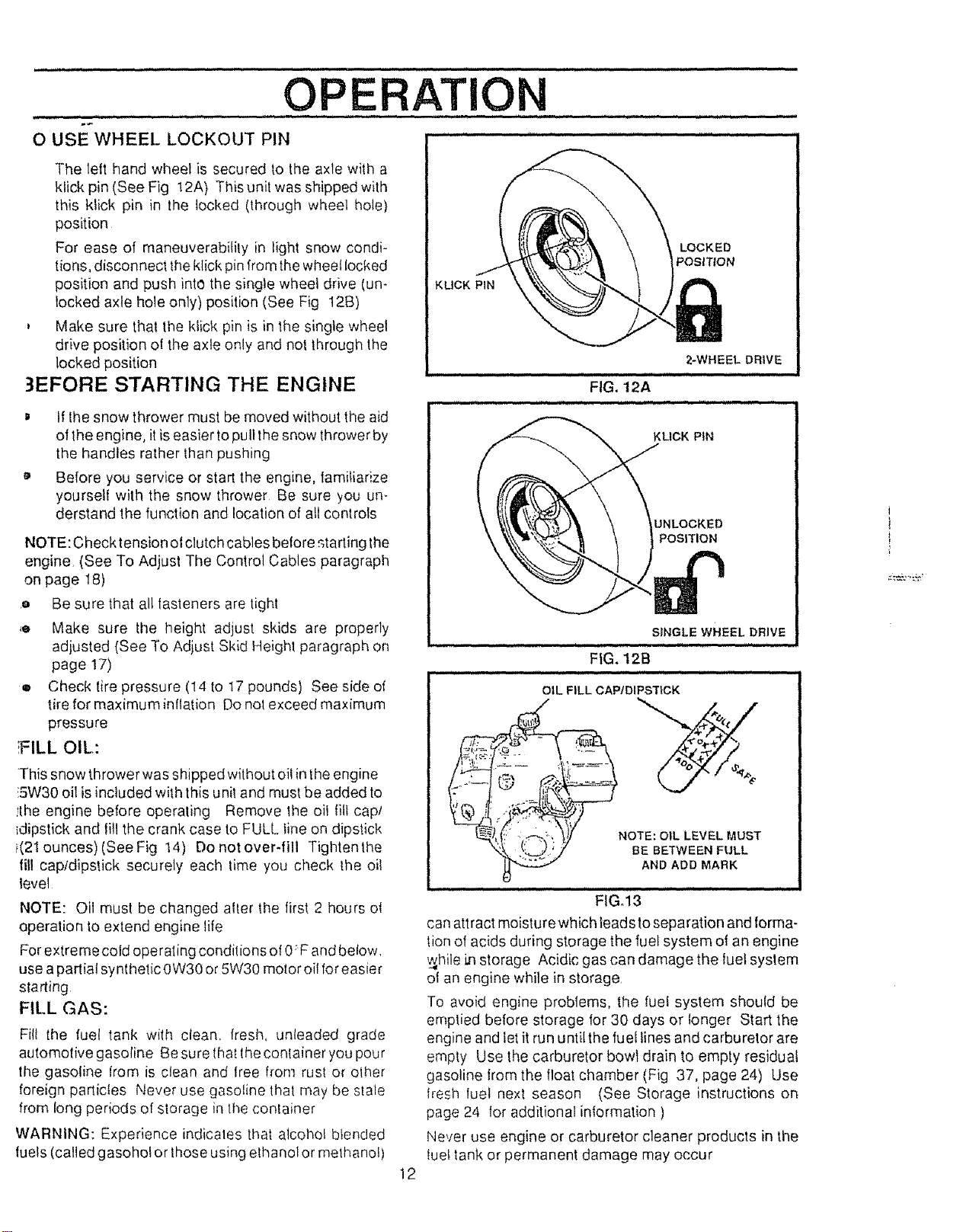
O USE WHEEL LOCKOUT PIN .................
The lett hand wheel is secured to the axle with a
klick pin (See Fig 12A) This unit was shipped with
this klick pin in the locked (through wheel hole)
position
For ease of maneuverability in light snow condi-
lions, disconnect the klick pin from the wheel locked
position and push into the single wheel drive (un-
locked axle hole only) position (See Fig 12B)
, Make sure that the klick pin is in the single wheel
drive position ol the axle only and not through the
locked position
3EFORE STARTING THE ENGINE
D If the snow thrower must be moved without the aid
of the engine, itis easier to pultthe snow thrower by
the handles rather than pushing
a, Before you service or start the engine, familiarize
yourself with the snow thrower Be sure you un-
derstand the function and location of all controls
NOTE: Check tension ot clutch cables before._tarting the
engine (See To Adjust The Control Cables paragraph
on page 18)
.o Be sure that all lasteners are tight
,o Make sure the height adjust skids are properly
adjusted (See To Adjust Skid Height paragraph on
page 17)
e Check tire pressure (I4 to t7 pounds) See side of
tire for maximum inflation Do not exceed maximum
pressure
;FILL OIL:
This snow thrower was shipped without oil in the engine
!5W30 oil is included with this unit and must be added to
!the engine before operaling Remove the oil fill cap/
_dipstick and lill the crank case to FULL line on dipstick
i(21 ounces) (See Fig 14) Do not over-fill Tightenthe
fill capldipstick securely each _ime you check Ihe oi!
level
NOTE: Oil must be changed after the lirs_ 2 hours o{
operation to extend engine life
For extre mecold operating condilions of 0: F and below.
use a partial synthetic 0W30 or 5W30 motor oil for easier
starting
FILL GAS:
Fill the fuel tank with clean, fresh, unleaded grade
automotive gasoline Be sure lhat the conlainer you pour
the gasoline from is clean and free from rust or olher
foreign particles Never use gasoline thai may be stale
from long periods of storage in the confainer
WARNING: Experience indicates tl_a_alcohol blended
fuels (called gasoholor those using elhanol or methanol)
KUCK PIN
. ill, i
12
LOCKED
POSITION
2-WHEEL DRIVE
i
FIG. t2A
KLtCK PIN
UNLOCKED
POSITION
SINGLE WHEEL DRIVE
INH I I.I I I.I Jl'
FIG. 12B
i,, iiJJ. ,i,l,, ii . i,.i,ii
OIL FiLL CAPfDIPSTiCK
NOTE: OIL LEVEL MUST
BE BETWEEN FULL
AND ADD MARK
i JJ,,,i
FiGoi3
can attract moisturewhich leads to separation and forma-
tion of acids during storage the fuel system of an engine
w_hilei,nstorage Acidic gas can damage the luet system
ol an engine while in storage.
To avoid engine problems, the fuel system should be
emptied before storage for 30 days or longer Start the
engine and let it run until the fuel lines and carburetor are
empty Use the carburetor bowl drain to empty residual
gasoline kom the float chamber (Fig 37, page 24) Use
flesh luel next season (See Storage instructions on
page 24 for additional information )
Never use engine or carburetor cleaner products in the
tuel tank or permanent damage may occur

,, ,,,,,,,,,,,,, , ,,,,, ,,,,,, ......................................................
OPERATION
TO STOP ENGINE
o To stop engine, move the throttle control lever to
STOP position and remove key. Keep the key in a
safe place. The engine will not start without the key
CARBURETOR
The factory settings for the carburetor are for most
conditions_ If the engine isoperated underthe foltowing
conditions, you can adjust carburetor mixture. See
"How To Adjust The Carburetor"(See Service and Ad-
justments, page 22).
• The engine has a loss of power or does not run
smooth..
• The engine's operated above 4,000 feet.
TO START ENGINE
Be sure that the engine has sufficient oil. Before starting
the engine, be certain that you have read the following
information:
COLD START (See Fig. 14)
• Be sure the auger drive and the traction drive
levers are in the disengaged RELEASED positionL
® Move the throttle control to RUN position
® Push the key into the ignition slot Be sure itsnaps
into place. Do not turn key. Remove the plastic
bag and store extra key in a safe place
• Rotate choke control to FULL choke position _
® Press the primer button in cold weather. Press
two or three times, while keeping your finger over
the vent hole on the primer button Release finger
between primes Additional priming may be neces-
sary for the first start ifthe temperature isbelow 15"
F_Do not prime if temperature is above 50° F.
• Pull the starter handle rapidly. Do not allow the
handle to snap back, but allow it to rewind slowly
while keeping a firm hold on the starter handle.
• As the engine warms up and begins to operate
evenly, rotate the choke knob slowly to OFF
position. Ifthe engine falters, return to FULL choke,
then slowly move to OFF choke position
NOTE: Allow the engine to warm up for a few minutes
because the engine will not develop full power until it
reaches operating temperature
• Run the engine at or near the top speed when
throwing snow
WARM START
If restarting a warm engine after a short shutdown,
rotate choke to OFF instead of FULL and do not push the
primer button.
FROZEN STARTER
If the starter is frozen and will not turn engine:
• Pul! as much rope out of the starter as possible
CHOKE
CON_OL
PRIMER
13
IGNITION RECOIL
KEY STARTER
THROTTLE CONTROL;
i H ==H= i i = H H,H,I=== =HI
FIG°14
i i iii i H,H,=,HH,,, i i ill iiliilil l i
_ CAUTION: GASOLINE IS FLAMMABLE
AND CAUTION MUST BE USED WHEN
HANDLING OR STORING IT.
DO NOT FILL FUEL TANK WHILE SNOW
THROWER IS RUNNING,WHEN IT tS HOT, OR
WHEN SNOW THROWER IS IN AN ENCLOSED
AREA.
KEEP AWAY FROM OPEN FLAME OR AN ELEC-
TRICAL SPARK AND DO NOT SMOKE WHILE
FILLING THE FUEL TANK.
NEVER FILL THE TANK COMPLETELY. FILL
THE TANK TO WITHIN1/4"- I/2" FROMTHETOP
TO PROVIDE SPACE FOR EXPANSION OF FUEL.
ALWAYS FILL FUEL TANK OUTDOORS AND
USE A FUNNEL OR SPOUT TO PREVENT SPILL-
ING.
MAKE SURE TO WIPE UP ANY SPILLED FUEL
BEFORE STARTING THE ENGINE.
STORE GASOLINE IN A CLEAN, APPROVED
CONTAINER AND KEEP THE CAP IN PLACE ON
.....THE CONTAINER. ,,,
• Release the starter handle and let it snap back
against the starter
If the engine still fails to start, push the primer button two
or three times again and repeat the two previous steps
until the engine starts. Then continue with the directions
for cold start.
To help prevent possible freeze-up of recoil starter and
engine controls, proceed as follows after each snow
removal job.
e Withtheenginerunning, pullthestarterropehard
with a continuous full arm stroke three or fourtit,: _,
Pulling of starter rope will produce a loud clatte_ '_
sound. This is not harmful to the engine or starter
o With the engine not running, wipe all snow and
moisture from the carburetor cover in area of control
levers Also move throltle control, choke control,
and starter handle several times.
OPE ATION
,ll i llllll i,,i lU ill
,L
D
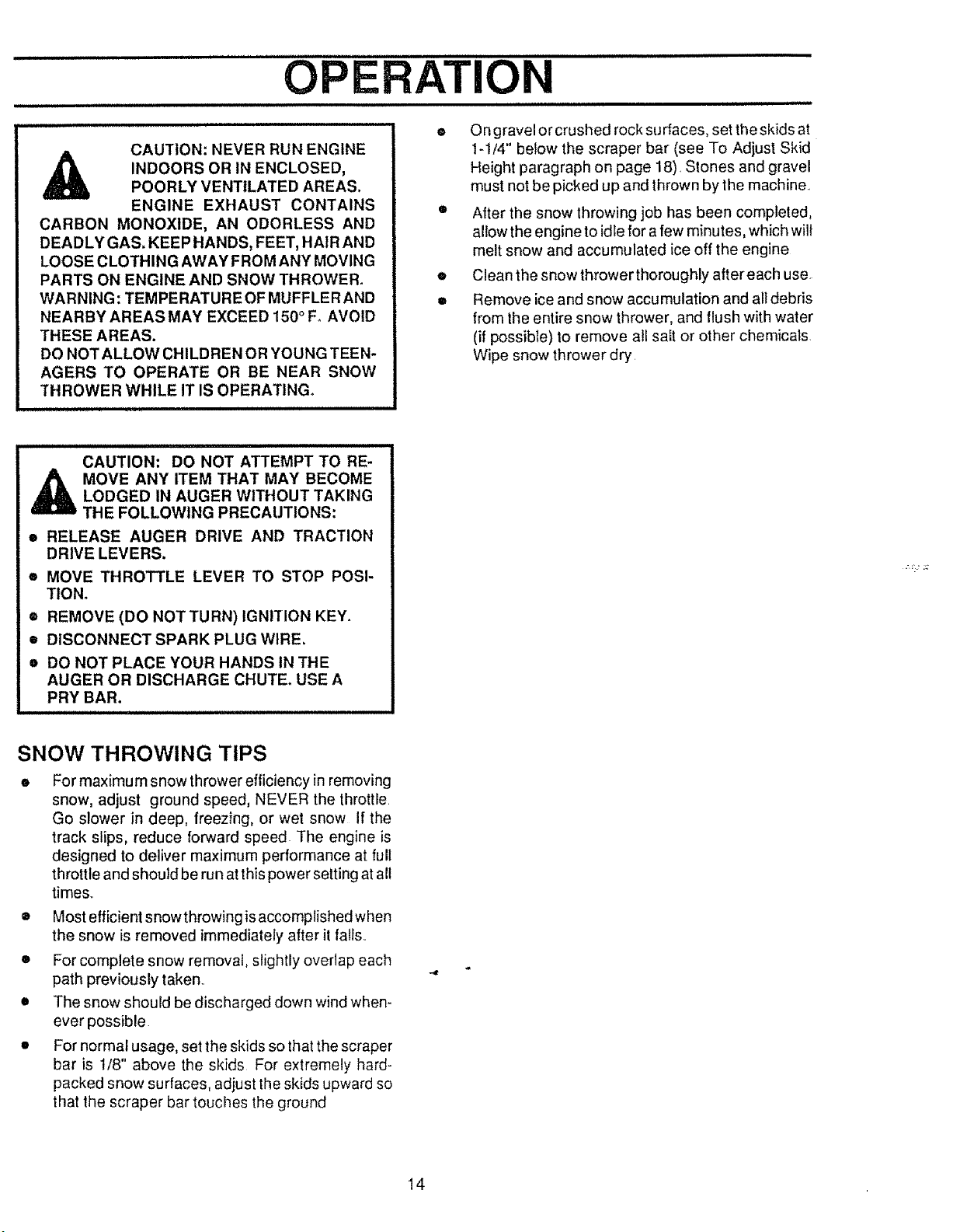
CAUTION: NEVER RUN ENGINE
INDOORS OR IN ENCLOSED,
POORLY VENTILATED AREAS.
ENGINE EXHAUST CONTAINS
CARBON MONOXIDE, AN ODORLESS AND
DEADLY GAS. KEEP HANDS, FEET, HAIR AND
LOOSE CLOTHING AWAY FROM ANY MOVING
PARTS ON ENGINE AND SNOW THROWER.
WARNING: TEMPERATURE OF MUFFLER AND
NEARBY AREAS MAY EXCEED 150 ° FoAVOID
THESE AREAS.
DO NOT ALLOW CHILDREN OR YOUNG TEEN-
AGERS TO OPERATE OR BE NEAR SNOW
THROWER WHILE IT IS OPERATING.
i i i u i i iii i iiiiiiiiiiiiiiiiiiiiiiiiiiii
O ngravel or crushed rock surfaces, set the skids at
I-1/4" below the scraper bar (see To Adjust Skid
Height paragraph on page 18)_Stones and gravel
must not be picked up and thrown by the machine..
• After the snow throwing job has been completed,
allow the engine to idle for a few minutes, which will
melt snow and accumulated ice off the engine
• Clean the snow thrower thoroughly after each use.
• Remove ice and snow accumulation and all debris
from the entire snow thrower, and flush with water
(if possibte) to remove all sait or other chemicals
Wipe snow thrower dry
CAUTION: DO NOT ATTEMPT TO RE-
,_ MOVE ANY ITEM THAT MAY BECOME
LODGED IN AUGER WITHOUT TAKING
THE FOLLOWING PRECAUTIONS:
• RELEASE AUGER DRIVE AND TRACTION
DRIVE LEVERS.
• MOVE THROTTLE LEVER TO STOP POSI-
TION,
® REMOVE (DO NOTTURN) IGNITION KEY.
• DISCONNECT SPARK PLUG WIRE.
e DO NOT PLACE YOUR HANDS IN THE
AUGER OR DISCHARGE CHUTE. USE A
PRY BAR.
SNOW THROWING TIPS
It For maximum snow thrower efiiciency in removing
snow, adjust ground speed, NEVER the throttle
Go slower in deep, freezing, or wet snow If the
track slips, reduce forward speed The engine is
designed to deliver maximum performance at full
throttle and should be run at this power setting at all
times_.
® Most efficient snowthrowing is accomplished when
the snow is removed immediately after it falls.
• For complete snow removal, slightly overlap each
path previously taken.
o The snow should be discharged down wind when-
ever possible.
• For normal usage, set the skids so that the scraper
bar is 1/8" above the skids For extremely hard-
packed snow surfaces, adjust theskids upward so
that the scraper bar touches the ground
14
......................................... , i, i, i iiii1,,,, i,, i iii 1,1, LI,
CUSTOMER RESPONSIBILITIE
H,,,,,,, , =,,, ,,, =H.,,. ,, , =,,,,,, =H,,, ,,,=.,,,,,,, =====,==,1,=,,, H, m,,,
GENERAL RECOMMENDATIONS .............................................
The warranty on this snow thrower does not cover items
that have been subjected to operator abuse or negli-
gence To receive full value from the warranty, operator
must maintain snow thrower as instructed inthis manual.
Some adjustments will need to be made periodically to
properly maintain your snow thrower
All adjustments inthe Service and Adjust ments section of
this manual should be checked at least once each
season
AFTER FIRST USE
" Check for any loose or damaged parts
• Tighten any loose fasteners
• Check and maintain the auger
• After each use, remove all snow and slush off the
snow thrower to prevent freezing of auger or con-
trois
o Check controls to make sure they are functioning
properly
o If any parts are worn or damaged, replace imme-
diately
SNOW THROWER
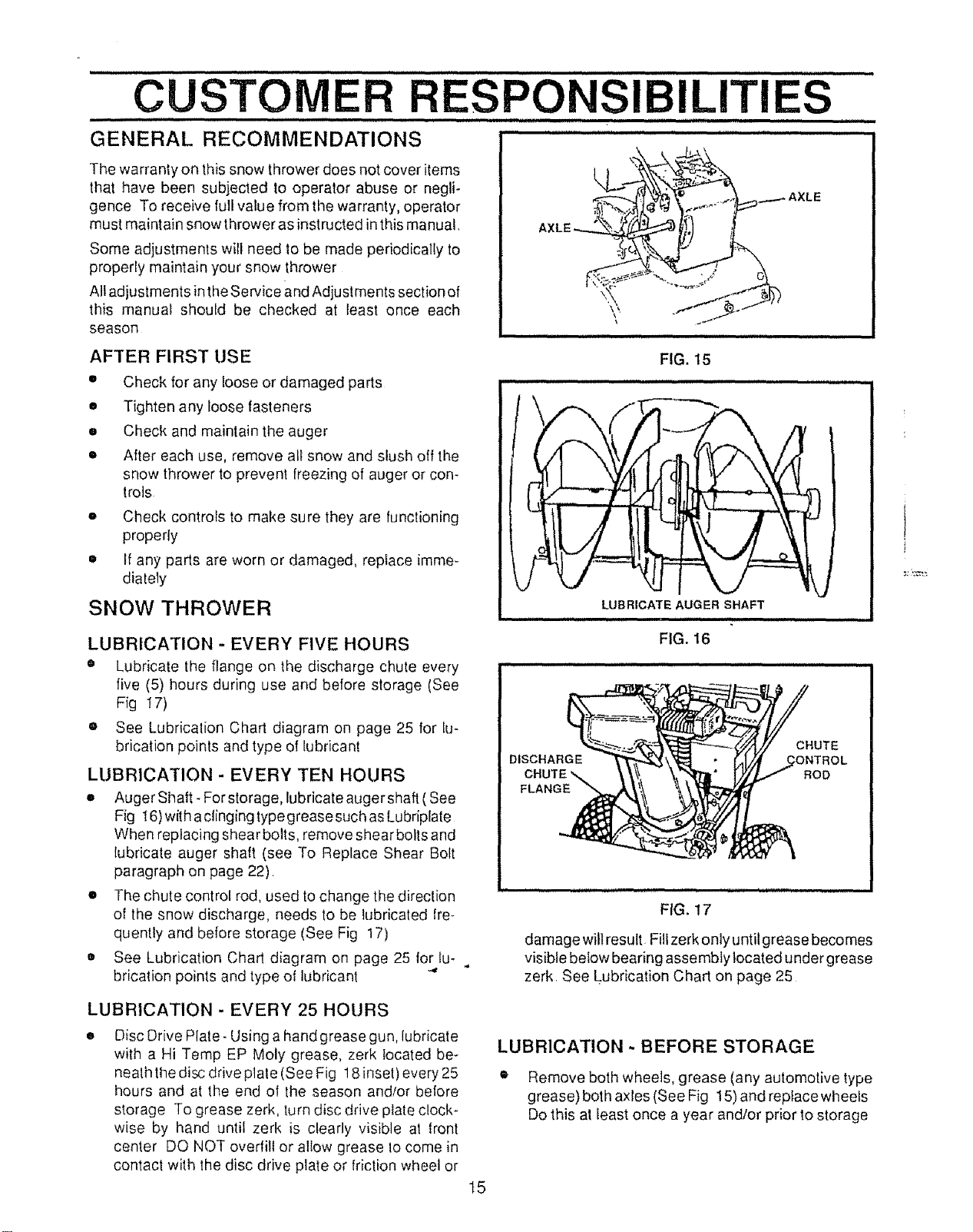
LUBRICATION - EVERY FIVE HOURS
• Lubricate the flange on the discharge chute every
five (5) hours during use and before storage (See
Fig 17)
® See Lubricalion Chart diagram on page 25 for lu-
brication points and type of lubricant
LUBRICATION - EVERY TEN HOURS
* Auger Shaft- For storage, lubricate auger shaft (See
Fig 16) with aclinging type grease such asLubriplaie
When replacing shear bolts, remove shear botts and
lubricate auger shaft (see To Replace Shear Bolt
paragraph on page 22)
* The chute control rod, used to change the direction
of the snow discharge, needs to be lubricated fre-
quently and before storage (See Fig 17)
o See Lubrication Chart diagram on page 25 for lu-
brication points and type of lubricant "'
FIG. 15
,,,,,,, , ,,,,,,, i
LUBRICATE AUGER SHAFT
i i ii1,1,1,,, i i1,.
FIG. 16
:_HUTE
DISCHARGE _l_ \_ • _IL//_ _CONTROL
CHUTE _ tt _ \,_','_1" t/Y/_ '''" ROD
FLAN__
FIG. 17
damage will result Fillzerk only until grease becomes
visible below bearing assembly located under grease
zerk. See Lubrication Chart on page 25
LUBRICATION - EVERY 25 HOURS
Disc Drive Plate- Using a hand grease gun, lubricate
with a Hi Temp EP Moly grease, zerk located be-
neath the disc drive plate (See Fig 18 inset) every 25
hours and at the end of the season and/or before
storage To grease zerk, turn disc drive plate clock-
wise by hand until zerk is clearly visible at lront
center DQ NOT overtilt or allow grease 1ocome in
contact with the disc drive plate or friction wheel or
LUBRICATION - BEFORE STORAGE
• Remove both wheels, grease (any automotive type
grease) both axles (See Fig 15) and reptacewheels
Do this al least once a year and/or prior to storage
t5

i =ll,, i i i,i , i= ,lll,l,,i, =IHI=I = ,= H,H= -
CUSTOMER RESPONSIBILITIES
N,i ii,i, ............................t=
LUBRICATION HEX SHAFT AND GEARS
• Hex Shaft and Gears - Hex shaft and gears require
no lubrication All bearings and bushings are lifetime
lubricated and require no maintenance (See Fig 18)
NOTE: Any greasing or oiling of the above components
can cause contamination of the friction wheel it the disc
drive plate or friction wheel come in contact with grease
or oil, damage to the friction wheel will result
Should grease or oil come in contact with the disc drive
plate or friclion wheel, be sure to clean the plate and
wheel thoroughly
NOTE: For storage, the hex shall and gears should be
wiped with 5W-30 motor oil to prevent rusting (See Fig
18)
e Auger Gear Box - The auger gear box has been
factory lubricated for life Iffor some reason lubricant
should leak out, have auger gear case checked by a
competent repairman
ENGINE
LUB RiCATION
Check the crankcase oil level (See Fig 19) before
starting the engine and after each five (5) hours ot
continuous use Add S A E 5W-30 motoroil as needed
Tighten fill cap/dipstick securely each time you check the
oil level S AE 5W-30 motor oil may be used to make
starting easier in areas where the temperature is 20" For
lower
OIL RECOMMENDATION
Only use high quality detergent oil rated with API service
classitication SG Select the oil's viscosity grade accord-
ing to your expected operating temperature:
RECOMMENDED VISCOSITY GRADES
|co
LDER<_ _>WARMER
5W30 SAE30
NOTE: Although multi-viscosity oils improve starting in
cold weather, these multi-viscosity oils will result in in-
creased oil consumption when used above 32:F Check
your engine oil level more frequently to avoid possible
engine damage from running low on oil
Change the oil after first lwo hours ol operation and every
25 hours thereafter or at least once a year if tl_e snow
thrower is nol used for 25 hours (See Fig 20)
• Position snow thrower so that the oil drain plug is
lowest point on the engine Remove of! drain plug
and oil lill cap/dipstick Drain oil into a suitable
container Oil wilt drain more freely when warm
WHEEL
(Require No
Lu brication)
/
/
DRIVE
•, PLATE
ZERK
OIL FiLL CAP_
DIPSTICK
_OIL DRAIN PLUG
FIG. 20
• Replace oil drain plug and tighten securely Refill
crankcase with SAE 5W30 motor oil
SPARK PLUG
=, Make sure that the spark plug is tightened securely
into theengine and the spark plug wire is attached
1othe spark plug
• If a torque wrench is available, torque plug to 18 to
23 foot pounds
• Clean the area around the spark plug base before
removal lo prevenl dirt from entering the engine
Clean the spark plug and reset the gap periodically
at 030 inch
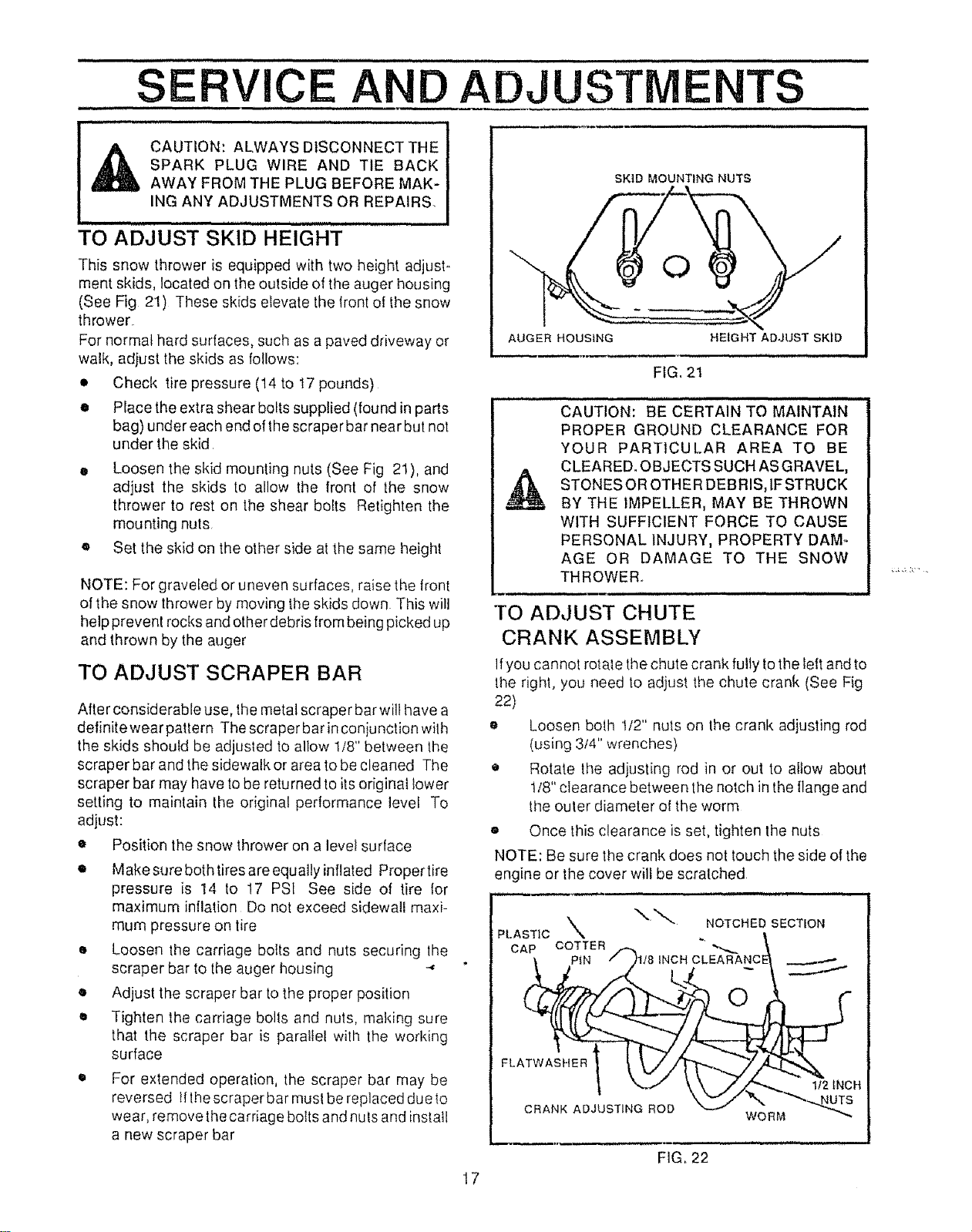
Thissnowthrowerisequippedwithtwoheightadjust-
meritskids,locatedonthe outside of the auger housing
(See Fig 21) These skids elevate the front of the snow
thrower
For normal hard surfaces, such as a paved driveway or
walk, adjust the skids as follows:
• Check tire pressure (14 to 17 pounds)
• Place the extra shear bolts supplied (found in parts
bag) under each end of the scraper bar near but not
under the skid
• Loosen the skid mounting nuts (See Fig 21), and
adjust the skids to allow the front of the snow
thrower to rest on the shear bolts Retighten the
mounting nuts,
• Set the skid on the other side at the same height
NOTE: For graveled or uneven surfaces, raise the front
of the snow thrower by moving the skids down This wilt
help prevent rocks and other debris from being picked up
and thrown by the auger
TO ADJUST SCRAPER BAR
After considerable use, the metal scraper bar wilt have a
definitewearpattern The scraperbarinconjuncfionwith
the skids should be adjusted to allow tt8" between the
scraper bar and the sidewalk or area tobe cleaned The
scraper bar may have to be returned to its original lower
setting to maintain the original pertormance level To
adjust:
• Position the snow thrower on a level surface
• Make sure both tires are equally inflated Propertire
pressure is 14 to 17 PSI See side of tire {or
maximum inflation Do not exceed sidewall maxi-
mum pressure on tire
• Loosen the carriage bolts and nuts securing lhe
scraper bar to the auger housing -"
o Adjust the scraper bar to the proper position
• Tighten the carriage bolts and nuts, making sure
that the scraper bar is parallel with the working
surface
SKID MOUNTING NUTS
For extended operation, the scraper bar may be
reversed lflhe scraper bar must be replaced due to
wear, remove the carriage bolts and nuls and install
a new scraper bar
AUGER HOUSING
HEIGHT ADJUST SKID
FIG. 2t
........................... _ i i i i innllU
CAUTION: BE CERTAIN TO MAINTAIN
PROPER GROUND CLEARANCE FOR
YOUR PARTICULAR AREA TO BE
CLEARED, OBJECTS SUCH AS GRAVEL,
STONES OR OTHER DEBRIS, IFSTRUCK
BY THE IMPELLER, MAY BE THROWN
WITH SUFFICIENT FORCE TO CAUSE
PERSONAL INJURY, PROPERTY DAM-
AGE OR DAMAGE TO THE SNOW
THROWER..
i , ,i ,,, i i
TO ADJUST CHUTE
CRANK ASSEMBLY
If you cannot rotate the chute crank fully to the left and to
the right, you need to adjust the chute crank (See Fig
22)
o Loosen both t/2" nuts on the crank adjusting rod
(using 3/4" wrenches)
• Rotate the adjusting rod in or out to allow about
t/8" clearance between the notch in the flange and
the outer diameter o! the worm
e Once this clearance is set, tighten the nuts
NOTE: Be sure the crank does not touch the side of the
engine or the cover will be scratched
PLASTIC\. NOTC.EO.SECT ON
CAP COTTER _ "_,_._
_. PiN /h/8 INCH CLEARANCE] .__,..-..-..
FL
_ '-.,.-tz \ \ /z Z"_ 112iNCH
C.AN ,,O.',ST,NORO0
" WORM
FIG,, 22
17
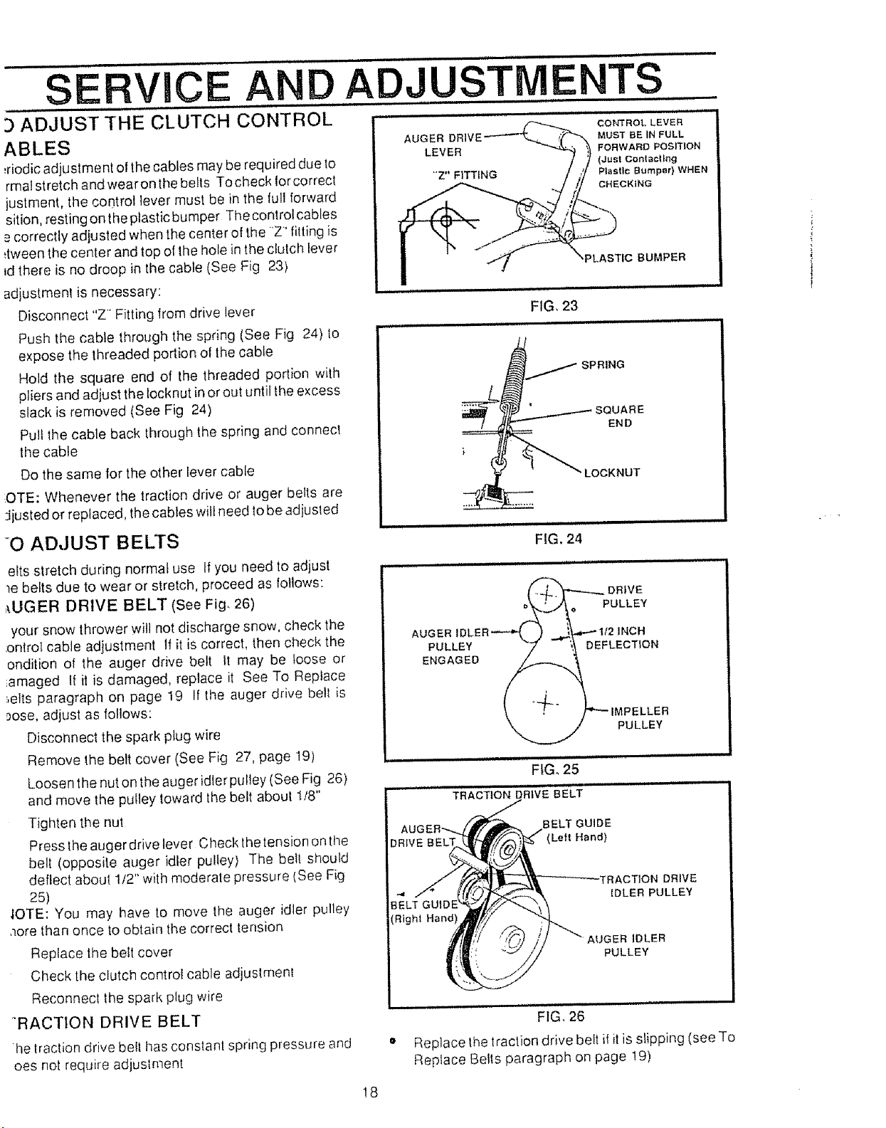
3 ADJUST THE CLUTCH CONTROL
ABLES
_riodicadjustment of the cables may be required due to
rmat stretch and wear on the bells Tocheck lor correct
justment, the control lever must be in the full forward
sition, restingontheptasticbumper Thecontrolcables
e correctly adiusted when the center of the 'Z' tilting is
_tween the center and top of Ihe hole in the clutch lever
_dthere is no droop in the cable (See Fig 23)
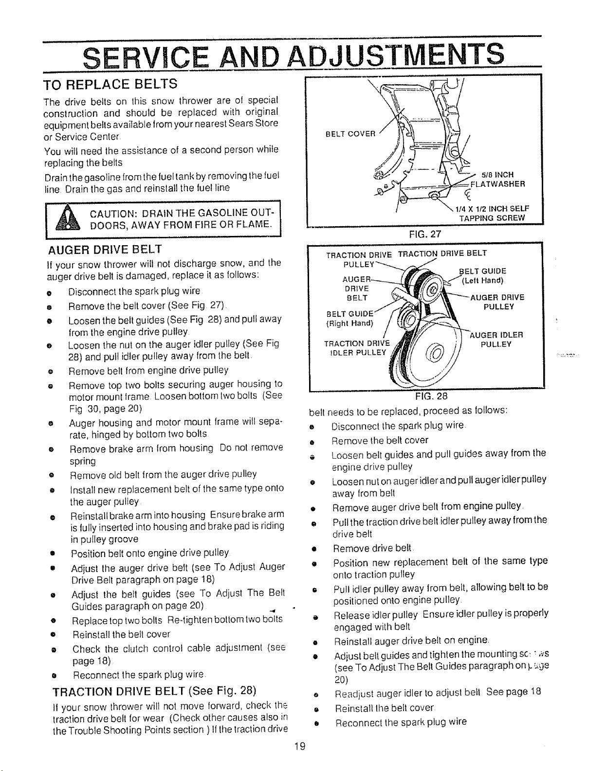
adjustmenl is necessary:
Disconnect "Z' Fitting lrom drive lever
Push the cable through the spring (See Fig 24) to
expose the threaded portion of the cable
Hold the square end of the threaded portion with
pliers and adjust the tocknut in or out until the excess
slack is removed (See Fig 24)
Pull the cable back through the spring and connect
the cable
Do the same for the other lever cable
OTE: Whenever the traction drive or auger belts are
Jiusted or replaced, the cables w{IIneed to be adjusted
"O ADJUST BELTS
AUGER
LEVER
CONTROL LEVER
MUST BE IN FULL
I ORWARD PQsrrloN
(Just cortt acting
Plastic Bumper} WHEN
CHECKING
,PLASTIC BUMPER
FIG, 23
inlH,, i, lU ,H,ll u,,p ,
.................. ,tllll
END
LOCKNUT
FIG. 24
efts stretch during normal use If you need to adjust
_e belts due to wear or stretch, proceed as follows:
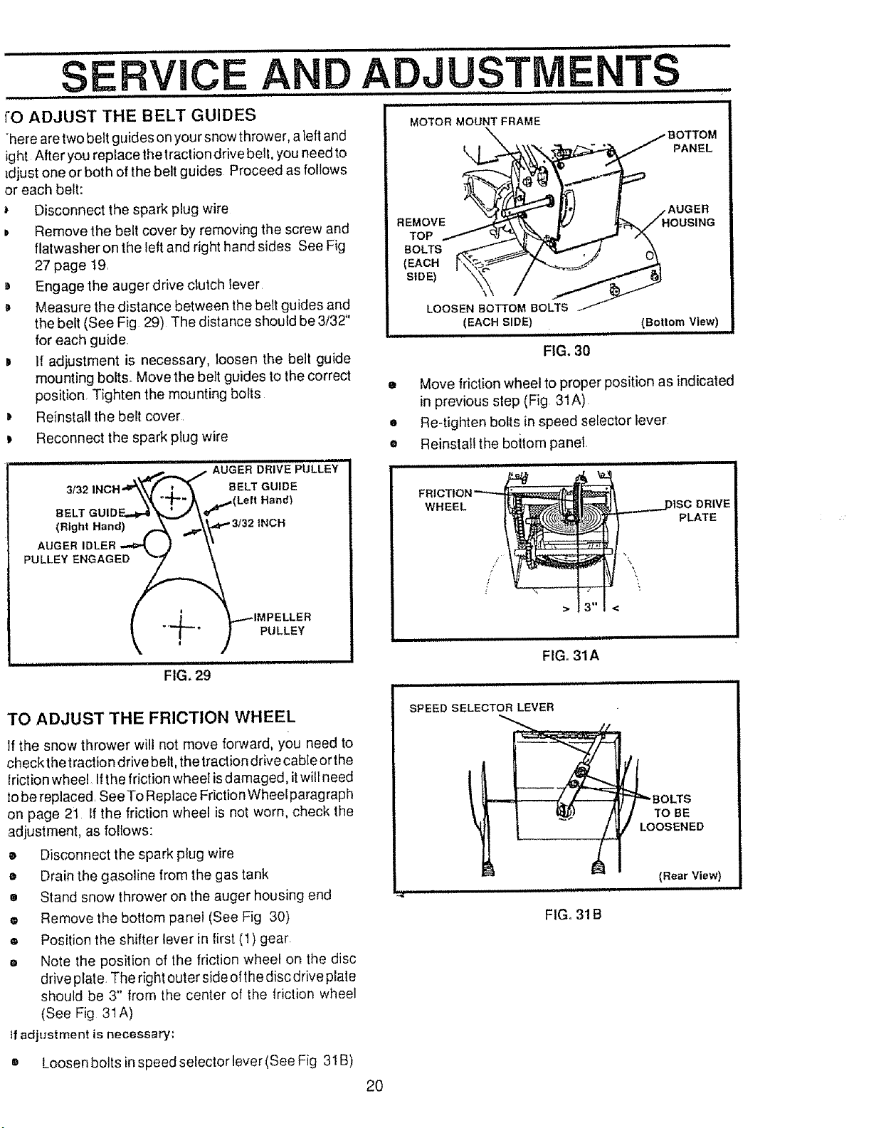
,_UGER DRIVE BELT (See Fig_ 26)
your snow thrower will not discharge snow, check the
:ontrol cable adjustment If it is correct, then check the
ondition of the auger drive belt It may be loose or
_amaged If it is damaged, replace it See To Replace
:,ells paragraph on page 19 If the auger drive belt is
rose, adjust as follows:
Disconnect the spark plug wire
Remove the belt cover (See Fig 27, page 19)
Loosen the nut on the auger idler pulley (See Fig 26)
and move the pulley toward the belt about 1/8"
Tighten the nut
Press the auger drive lever Check the tension onthe
belt (opposite auger idler pulley) The belt should
deflect about 112'"with moderate pressure (See Fig
25)
IOTE: You may have to move the auger idler pulley
_ore than once to obtain the correct tension
Replace the be!t cover
Check the clutch control cable adjuslment
Reconnecf the spark plug wire
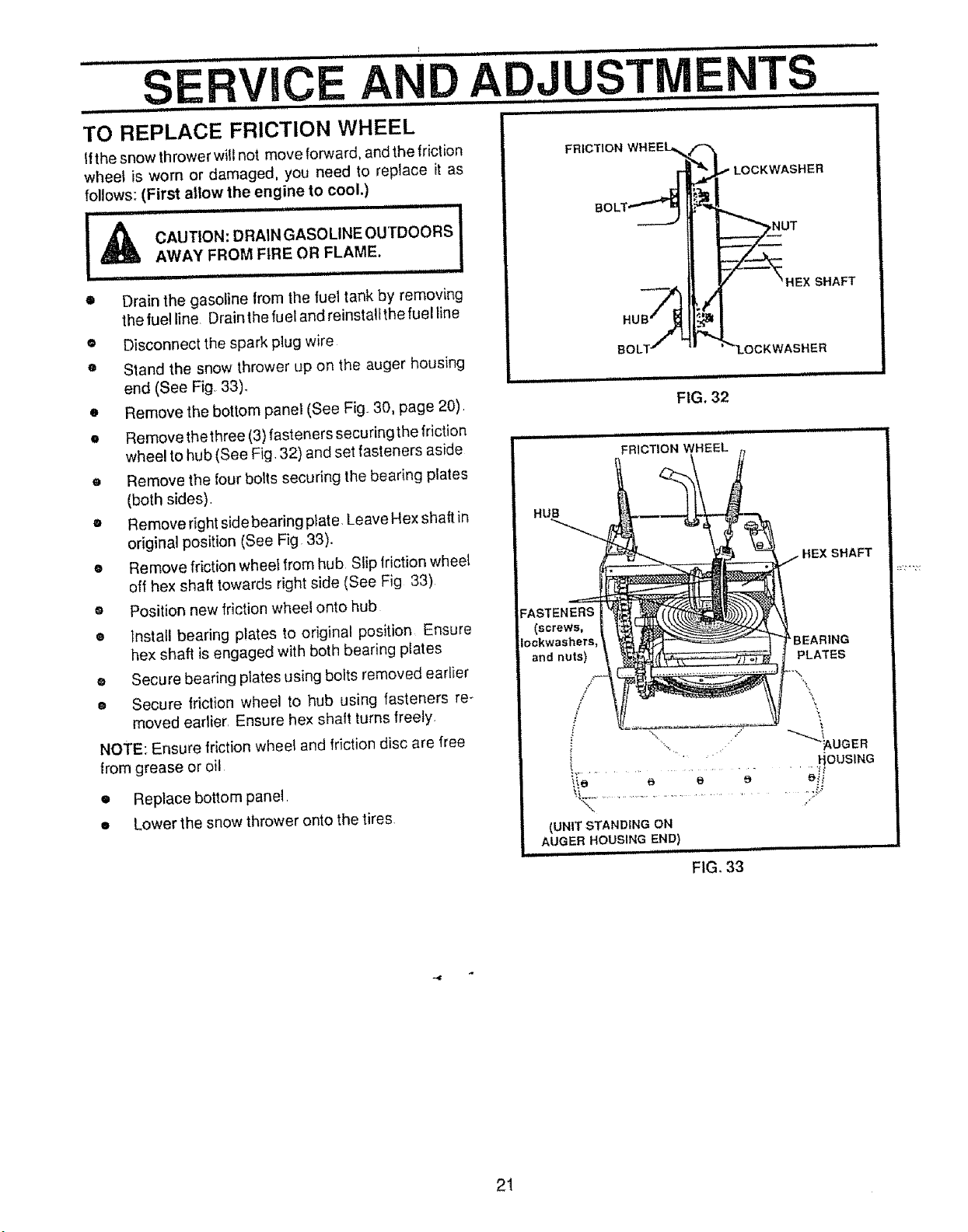
°RACTION DRIVE BELT
__ DRIVE
POLLE,,
AUGERlULER----%) _.jF.---It2INCH
\ ' ,/"_'_ IMPELLER
PULLEY
ii i1[ iiiiiiii i I I iiiiiiiiii ii iii iiill I I
FIG_ 25
(Right
;ACTION DRIVE
IDLER PULLEY
AUGER IDLER
PULLEY
FIG, 26
he traction drive bell has constanl spring pressure and
Des not require adjustment
• Replace the traction drive belt it it is slipping (see To
Replace Belts paragraph on page !9)
!8
SE
, ............................................ i, H,Jl
TO REPLACE BELTS
The drive belts on this snow lhrower are ol special
construction and should be replaced with original
equipment belts available from your nearest Sears Store
or Service Center
You will need lhe assistance of a second person while
replacing the belts
Drain the gasoline from the fuel tank by removing the tuei
line Drain the gas and reinstall the fuel line
OT,O. i
DOORS, AWAY FROM FfRE OR FLAME_ I
AUGER DRIVE BELT
If your snow thrower will not discharge snow, and the
auger drive belt is damaged, replace it as follows:
e Disconnect the spark plug wire
® Remove the belt cover (See Fig 27)
• Loosen the belt guides (See Fig 28) and pulf away
from the engine drive pulley
e Loosen the nut on the auger idler pulley (See Fig
28) and pull idler pulley away from the belt
• Remove belt from engine drive pulley
o Remove top two bolts securing auger housing to
motor mount frame Loosen bottom two bolts (See
Fig 30, page 20)
o Auger housing and motor mount frame wilt sepa-
rate, hinged by bottom two bolts
® Remove brake arm from housing Do not remove
spring
o Remove old belt from the auger drive pulley
o Install new replacement belt of the same type onto
the auger pulley
• Reinstall brake arm into housing Ensurebrake arm
is lully inserted into housing and brake pad is riding
in pulley groove
g Position belt onto engine drive pulley
• Adjust the auger drive belt (see To Adjust Auger
Drive Belt paragraph on page t8)
• Adjust the belt guides (see To Adjust The Belt
Guides paragraph on page 20) _,
o Replace top two bolts Re-tighten bottom two bolts
o Reinstall the belt cover
• Check the clulch control cable adjustment (see
page I8)
Reconnect the spark plug wire
O
TRACTION DRIVE BELT (See Fig. 28)
If your snow thrower will not move forward, check the
traction drive belt for wear (Check other causes afso in
the Trouble Shooling Points section ) If the _raction drive
VICE AND ADJUSTMENTS
BELT COVER /
FIG. 27
.................................. iiii i
TRACTION DRIVE TRACTION DRIVE BELT
DRIVE
BELT
BELT
(RighL Hand)
TRACTION DRIVE
IDLER PULLEY
BELT GUIDE
DRIVE
PULLEY
IDLER
PULLEY
........................................ .i
FIG. 28
belt needs to be replaced, proceed as Iotlows:
e Disconnect the spark plug wire
• Remove the bell cover
Loosen belt guides and pull guides away from the
engine drive pulley
• Loosen nut on auger idler and pull auger idler pulley
away from betl
• Remove auger drive belt from engine pulley
• Pull the traction drive belt idler pulley away from the
drive belt
Remove drive belt
• Position new replacement belt of the same type
onto traclion pulley
o Pull idler pulley away from belt, aTIowing belt to be
positioned onto engine pulley
Release idler pulley Ensure idler pulley is properly
engaged with belt
• Reinstall auger drive belt on engine
• Adiust belt guides and tighten the mounting so: : ,;Js
(see To Adjust The Belt Guides paragraph on _.-'._ge
2O)
Readjust auger idler to adjust bell See page t8
Reinstall lhe belt cover
o
O
e Reconnect the spark plug wire
19
................ ii i i
SERVICE AN
i1, i,,, , ii m,,,,,,,,,,H ii ,,,,,n
rO ADJUST THE BELT GUIDES
here aretwo belt guides on your snow thrower, a left and
ight After you replace the traction drive belt, you need to
_djust one or both of the belt guides Proceed as follows
or each belt:
Disconnect the spark plug wire
D Remove the belt cover by removing the screw and
flatwasher on the left and right hand sides See Fig
27 page 19.
D Engage the auger drive clutch lever
Measure the distance between the belt guides and
the belt (See Fig 29) The distance should be 3/32"
for each guide.
IH H, r I, IHHI I, I I I1,,,1,1
ADJUSTIVIE TS
MOTOR MOUNT FRAME
\\ _._ BOTTOM
SIDE) I
LOOSEN BOTTOM BOLTS
IEAC.S,DEI................ cao.t.lo,.Vi.ewl
D If adjustment is necessary, loosen the belt guide
mounting bolts. Move the belt guides to the co_'rect
position. Tighten the mounting bolts
D Reinstall the belt cover.
Reconnect the spark plug wire
......................, ._..-_ _ ._'UGER DRIVE PULLEY
3132 INCH"__ BELT GUIDE
BELT GUIDF_" "_._ _,.(Le|l Hand)
(Right Hand)A-- _\_"3132 INCH
_IMPELLER
FIG, 29
TO ADJUST THE FRICTION WHEEL
If the snow thrower will not move forward, you need to
check thetraction drive bell, the traction drive cable or the
Mction wheel Ifthe frictionwheel isdamaged, itwilt need
to be repiaced. See To Replace Friction Wheel parag raph
on page 21 If the friction wheel is not worn, check the
adjustment, as follows:
• Disconnect the spark plug wire
o Drain the gasoline from the gas tank
g Stand snow thrower on the auger housing end
® Remove the bottom panel (See Fig 30)
® Position the shifter lever in first (1) gear
o Note the position of the friction wheel on the disc
drive plate. The right outer side of thedisc drive plate
should be 3" from the center of the friction wheel
(See Fig 3tA)
If adjustment is necessary:
FIG. 30
• Move frictionwheel to proper position as indicated
in previous step (Fig 31A).
• Re-tighten bolts in speed selector Iever
® Reinstall the boitom panel.
IIH H IHI H,H ,i HH,,
_____DIscDR=VE
__ _ PLATE
3"1<
i,i ii
FIGo31A
SPEED SELECTOR LEVER
(Rear View)
FIG. 31B
= Loosen bolts in speed selector lever (See Fig 31B)
2O
................ ,,,,,,u . iii ii i iiii ii iiiiiii iiii L/ iiil/ LI ii iiiiiiiiiiiii I I I I iiiiiiiii I
SERVICE AND ADJUSTMENTS
H.L =,,,, H,H,,,= H= =,,H,, ,.,H = HH,N. =,
,,,N =,, .,, , . =1 '" ", ' "" I L
TO REPLACE FRICTION WHEEL
Ifthe snow thrower will not move forward, and the friction
wheel is worn or damaged, you need to replace it as
follows: (First allow the engine to cool.)
IA I
CAUTION: DRAIN GASOLINE OUTDOORS
AWAY FROM FIRE OR FLAME.
• Drain the gasoline from the fuel tank by removing
the fuel line Drain the fuel and reinsta!Ithe fuel {ine
• Disconnect the spark plug wire
• Stand the snow thrower up on the auger housing
end (See Fig 33)_
e Remove the botlom panet (See Fig 30, page 20)
e Remove the three (3) fasteners securing the friction
wheel to hub (See Fig 32) and set fasteners aside
e Remove the four bolts securing the bearing plates
(both sides)
• Remove right side bearing plate. Leave Hex shaft in
original position (See Fig 33).
e Remove friction wheel from hub Slip friction wheet
off hex shaft towards right side (See Fig 33)
o Position new friction wheel onto hub
e Install bearing plates to original position Ensure
hex shaft isengaged with both bearing plates
• Secure beating plates using bofts removed earlier
® Secure Ifiction wheel to hub using fasteners re-
moved eartier Ensure hex shalt turns freely
NOTE: Ensure friction wheel and friction disc are free
from grease or oil
• Replace bottom panel
• Lower the snow thrower onto the tires
HUB
HEX SHAFT
FASTENERS
(screws,
Iockwashers, 'BEARING
and nuts) PLATES
/ \
/ \
i .... ousmNG
(UNIT STANDING ON
AUGER HOUSING END)
I,,N i ii i.. ,i, L N, I
FIG. 33
21
i i ,i i inll i1 ii i lU,,,llll nnl i,nlll nil IlUl,,,i Inl, I I .... ,i Ii Ill
SERVICE A DADJUST TS
TO REPLACE AUGER SHEAR BOLT ................................
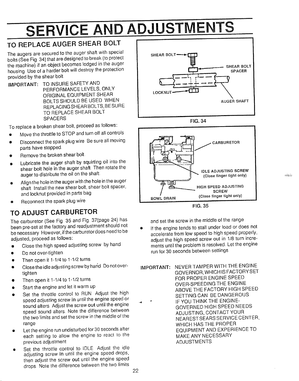
The augers are secured lo the auger shaft with special
bolls (See Fig 34) that are designed to break (to protect
the r0achine) if an object becomes lodged in the auger
housing Use of a harder bolt will destroy the protection
provided by the shear bolt
IMPORTANT: TO iNSURE SAFETY AND
PERFORMANCE LEVELS, ONLY
ORIGINAL EQUIPMENT SHEAR
BOLTS SHOULD BE USED WHEN
REPLACING SHEAR BOLTS, BE SURE
TO REPLACE SHEAR BOLT
SPACERS
To replace a broken shear boll, proceed as follows:
• Move the throttle to STOP and turn off al_controls
• Disconnect the spark plug wire Be sure all moving
parts have stopped
e Remove the broken shear bot{
= Lubricate the auger shaft by squirting oil into the
shear bolt hote in the auger shaft. Then rotate the
auger to distribute the oil on the shaft.
• A{ign the hole in the auger with the hole in the auger
shaft Install the new shear bolt, shear bo!l spacer,
and iocknut provided in parts bag
e Reconnect the spark plug wire
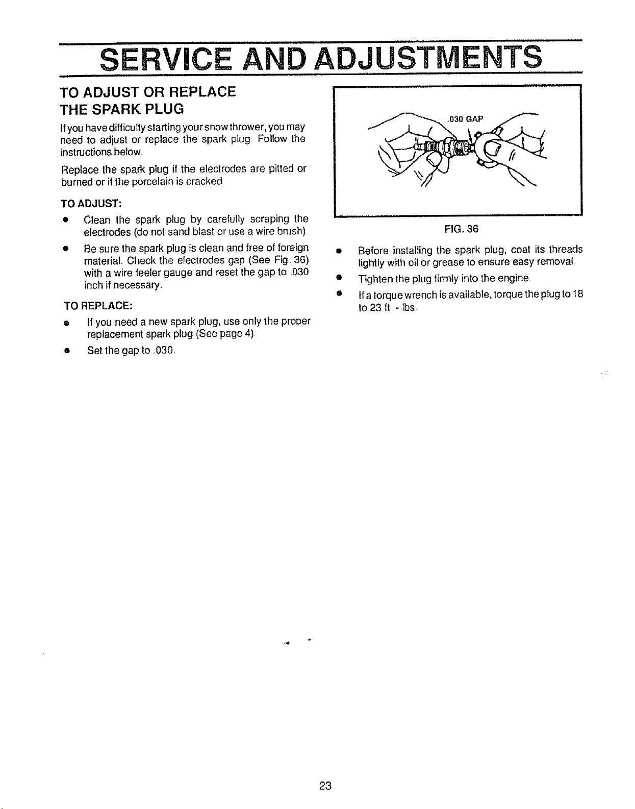
TO ADJUST CARBURETOR
The carburelor (See Fig 35 and Fig 37(page 24) has
been pre-set at the factory and readjustment should not
be necessary However, ifthe carburetor does need lo be
adjusted, proceed as follows:
• Close the high speed adjusting screw by hand
• Do not over4ighten
• Then open it 1-1/4 to 1-t/2 turns
• Close the idle adjusting screw by har_d Do not over-
tighten
• Then open it 1-1/4 to 1-1/2 turns
• Start the engine and let it warm up
• Set the throttle control to RUN Adjust the high
speed adjusting screw in unti! the engine speed or
sound alters Adjust the screw out until the engine
speed sound alters Note the difference between
the two limits and set the screw in the middle of lhe
range
• Let the engine run undisturbed for 30 seconds after
each setling Io allow lhe engine to reacl to the
previous adjustment
• Set the throttle control to IDLE Adjust the idle
adjusting screw in until the engine speed drops,
then adjust the screw out until the engine speed
drops Nole the difference between the two limits
SHEAR
LOCK NUT
SHEAR BOLT
SPACER
AUGER SHAFT
FIG. 34
i i iiiii L iiiu lit ill ii
j CARBURETOR
_ IDLE ADJUSTING SCREW
==_==_) (Close {inger tight only)
/ _t_,--=_.,____..,._ HiGH SPEED ADJUSTING
/_ SCREW
BOWL DRAIN (Close linger tight only)
I II II I IIIIIj IIU ii iiiii iiiiiiiiiiiii
FIG. 35
and set the screw in the middle of the range
If the engine tends to stall under load or does not
accelerate from tow speed to high speed properly,
adjust the high speed screw out in 1/8 turn incre-
ments until the problem is resolved. Let the engine
run for 30 seconds between settings
IMPORTANT: NEVER TAMPER WITH THE ENGINE
GOVERNOR, WHICH IS FACTORY SET
FOR PROPER ENGINE SPEED
OVER-SPEEDING THE ENGINE
ABOVE THE FACTORY HIGH SPEED
SETTING CAN BE bANGEROUS
IF YOU THINK THE ENGINE-
GOVERNED HIGH SPEED NEEDS
ADJUSTING, CONTACT YOUR
NEAREST SEARS SERVICE CENTER,
WHICH HAS THE PROPER
EQUIPMENT AND EXPERIENCE TO
MAKE ANY NECESSARY
ADJUSTMENTS
22
TO ADJUST OR REPLACE
THE SPARK PLUG
Ifyou have difficulty starting you r snow thrower, you may
need to adjust or replace the spark plug. Follow the
instructionsbelow,
Replace the spark plug if the electrodes are pitted or
burned or if the porcelain is cracked
TO ADJUST:
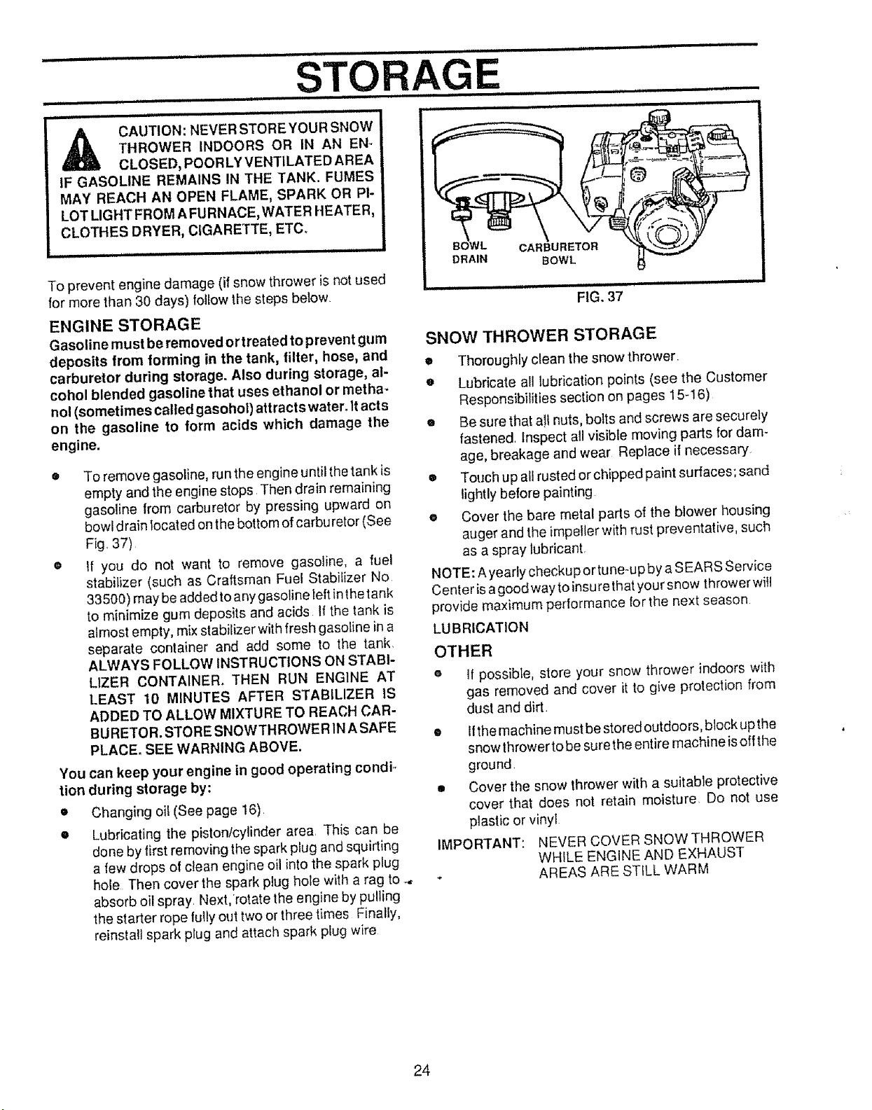
= Clean the spark plug by carefully scraping the
electrodes (do not sand blast or use a wire brush)
• Be sure the spark plug is clean and free of foreign
material. Check the electrodes gap (See Fig 36)
with a wire feeler gauge and reset the gap to ,030
inch if necessary.
TO REPLACE:
• If you need a new spark plug, use only the proper
replacement spark plug (See page 4)
• Set the gap to .030.,
.030 GAP
FIG. 36
• Before installing the spark plug, coat its threads
lightly with oil or grease to ensure easy removal,
• Tighten the plug firmly into the engine.
• If a torque wrench isavailable, torque the ptug to 18
to 23 ft - tbs,
23
==q ,L ,,= i =,,,,,,. = , ,=,,H,,, ==,,,,,i, 'ILL
CAUTION: NEVER STORE YOUR SNOW
THROWER INDOORS OR IN AN EN-
CLOSED, POORLY VENTILATED AREA
IF GASOLINE REMAINS IN THE TANK. FUMES
MAY REACH AN OPEN FLAME, SPARK OR PI-
LOT LIGHT FROM AFURNACE, WATER HEATER,
CLOTHES DRYER, CIGARETTE, ETC.
To prevent engine damage (if snow thrower is not used
for more than 30 days) follow the steps below
ENGINE STORAGE
Gasoline must be removed ortreated to prevent gum
deposits from forming in the tank, filter, hose, and
carburetor during storage. Also during storage, al-
cohol blended gasoline that uses ethanol or metha-
nol (sometimes called gasohol) attracts water. Itacts
on the gasoline to form acids whtch damage the
engine.
To remove gasoline, run the engine until the tank is
empty and the engine stops Then drain remaining
gasoline from carburetor by pressing upward on
bowl drain Iocated on the bottom ofcarburetor (See
Fig. 37)
If you do not want to remove gasoline, a fuel
stabilizer (such as Craftsman Fuel Stabifizer No
33500) may be added toany gasoline left inthetank
to minimize gum deposits and acids If the tank is
almost empty, mix stabilizer with fresh gasoline in a
separate container and add some to the tank.
ALWAYS FOLLOW INSTRUCTIONS ON STABI-
LIZER CONTAINER, THEN RUN ENGINE AT
LEAST 10 MINUTES AFTER STABILIZER IS
ADDED TO ALLOW MIXTURE TO REACH CAR-
BURETOR. STORE SNOWTHROWER 1NASAFE
PLACE. SEE WARNING ABOVE.
You can keep your engine in good operating condi_
tion during storage by:
* Changing oil (See page 16)
e Lubricating the piston/cylinder area. This can be
done by first removing the spark plug and squirting
a few drops of clean engine oil into the spark plug
hole Then cover the spark plug hole with a rag to
absorb oil spray. Next,'rotate the engine by pulting
the starter rope fully out two or three times Finally,
reinstall spark plug and attach spark plug wire
,,,,, ,,,,,,,,
FIG, 37
SNOW THROWER STORAGE
* Thoroughly clean the snow thrower.
e Lubricate all lubrication points (see the Customer
Responsibilities section on pages 15-16)
o Be sure that a!l nuts, bolts and screws are securely
fastened. Inspect all visible moving parts for dam-
age, breakage and wear Replace it necessary
® Touch up al! rusted orchipped paint surfaces; sand
lightly before painting
a Cover the bare metal parts of the blower housing
auger and the impeller with rust preventative, such
as a spray lubricant.
NOTE: A yearly checkupor tune-up by a SEARS Service
Cent er isa good way toinsu re thatyour snow thrower will
provide maximum performance for the next season
LUBRICATION
OTHER
e 1!possible, store your snow thrower indoors with
gas removed and cover it to give protection from
dust and dirt
IMPORTANT:
lithe machine must be stored outdoors, block up the
snow thrower to be sure the entire machine isoffthe
ground,
Cover the snow thrower with a suitable protective
cover that does not retain moisture. Do not use
plastic or vinyt
NEVER COVER SNOW THROWER
WHILE ENGINE AND EXHAUST
AREAS ARE STILL WARM
24
=H=NmIH
RVICE ECOMMENDA ONS
m= =m ,====,,,,,=
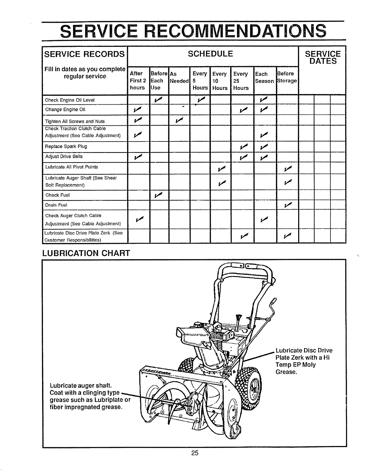
SERVICE RECORDS
Fill in dates as you complete
regular service
SCHEDULE
After Before As Every Every Every Each Before
First2 Each Needed 5 10 25 Season Storage
hours Use Hours Hours Hours
SERVICE
DATES
Check Engine Oil Level
,,,,,,,,i ........
Change Engine Oil
Tighten AII Screws and Nuts
Check Traction Crutch Cable
Adjustment (See Cable Adjuslment)
v" v" v"
Replace Spark Plug
Adjust Drive Belts
v' v"
Lubricate All Pivot Points
Lubricate Auger Shaft (See Shear
Bolt Replacement)
Check Fuel
Drain Fuel
Check Auger Clutch Cable
Adjustment (See Cable Adjustment)
Lubricate Disc Drive Plate Zerk (See
Customer Responsibilities)
v" v"
LUBRICATION CHART
Lubricate auger shaft.
Coat with a clin
grease such as Lubriplate or
fiber impregnated grease,
Lubricate Disc Drive
Plate Zerk with a Hi
Temp EP Moly
Grease.
\
25
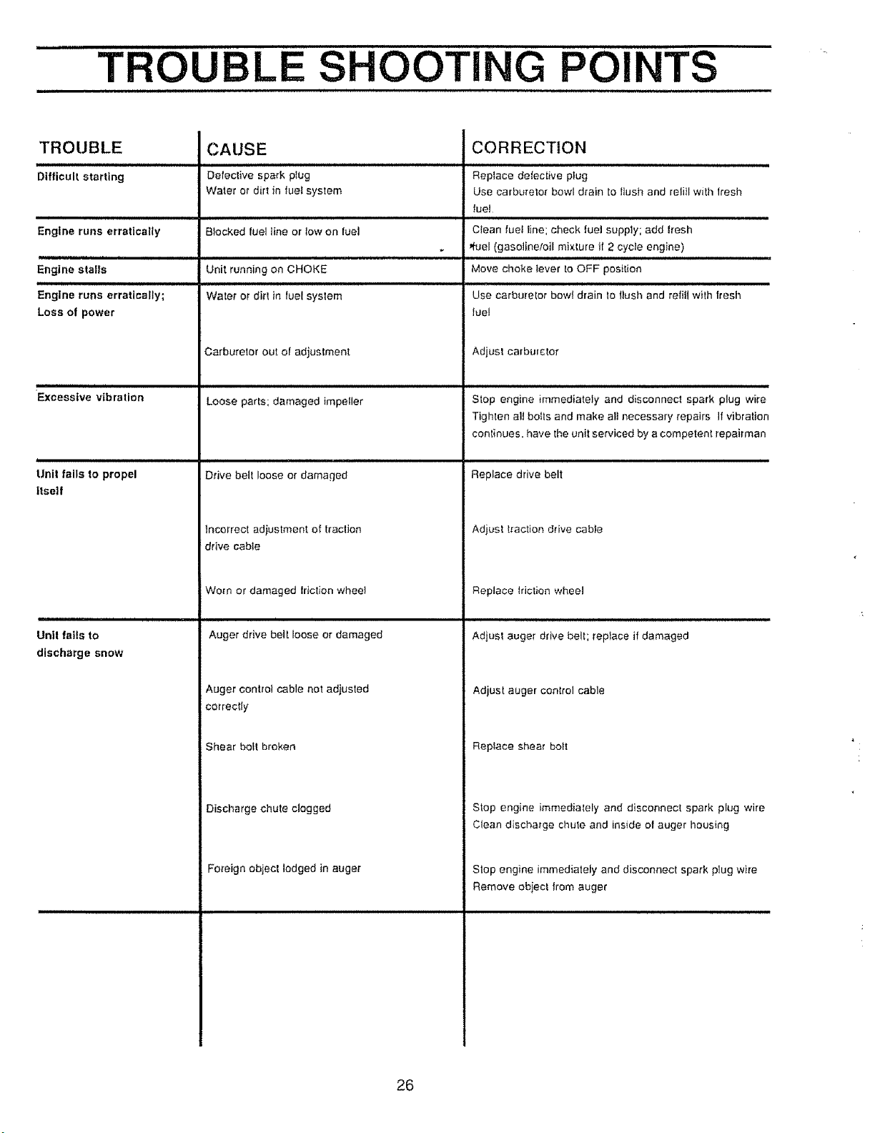
..... TROUBLE SHOOTING POINTS
................................................... i,. ,,.,, HH, ill II,t lU,II,J I UlUI
TROUBLE
Difficult starting
Engine runs erratically
Engine stalls
Engine runs erratically;
Loss of power
).n,l,.nr.nnnnln i i ii
Excessive vibration
i
Uni! fails to propel
itself
Unit fails to
discharge snow
CAUSE
Defective spark plug
Water or dirt in tue! system
Blocked fuel line or tow on fuel
Unit running on CHOKE
Water ot dirt in fuel system
Carburetor out of adjustment
Loose parts; damaged impeller
Drive belt loose or damaged
Incorrect adiustment of traction
drive cable
Worn or damaged friction whee!
Auger drive belt loose or damaged
Auger control cable not adjusted
CORRECTION
Replace defec{ive plug
Use carburetor bowl drain to flush and reli}lwith lresh
fue!
Clean luet tine; check fuel supply; add fresh
ffuel (gasoline,oil mixture if 2 cycle engine)
Move choke lever to OFF position
Use carburetor bow! drain to llush and refitl w}th fresh
fuel
Adjust carburetor
Stop engine immediately and disconnect spark plug wire
Tighten all boils and make al} necessary repairs If vibration
continues, have the unit serviced by a competent repairman
Replace drive belt
Adjust traction drive cable
Replace Motion wheel
Adjust auger drive belt; replace if damaged
Adjust auger control cable
correctly
Shear bollbroken
Discharge chute clogged
Fo_'eign object lodged in auger
Replace shear bolt
Stop engine immediately and disconnect spark plug wire
Clean discharge chute and inside of auger housing
Stop engine immediately and disconnect spark plug wire
Remove obiec! Irom auger
26

ii
NOTES
L J,
27
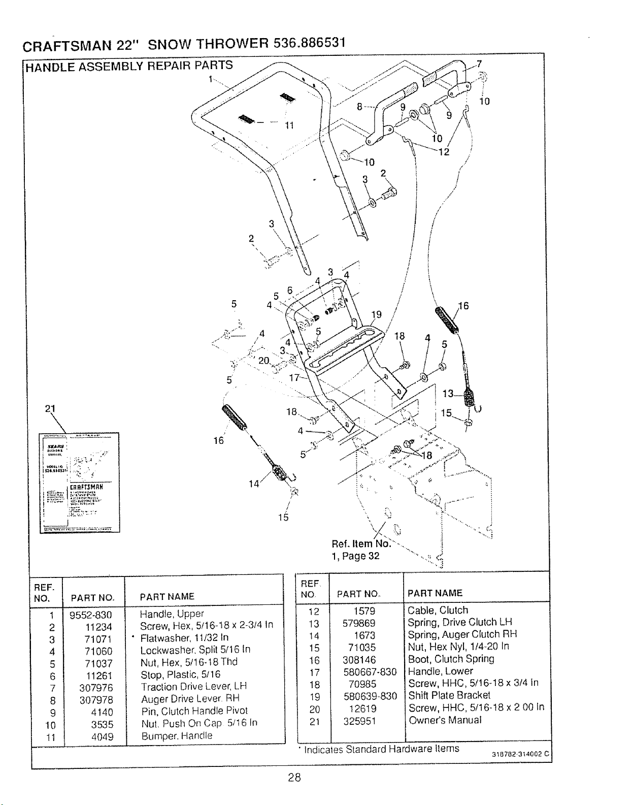
CRAFTSMAN 22" SNOW THROWER 536.886531
HANDLE ASSEMBLY REPAIR PARTS
1",
1t
4
5
5
2
!9
18
10
/
/
5
: 10
21
u
_F.
).
2
3
4
5
6
7
8
9
10
11
PART NO,
9552-830
11234
71071
71060
71037
11261
307976
307978
4140
3535
4049
PART NAME
Handle, Upper
Screw, Hex, 5/16-18 x 2-3/4 In
Flatwasher, 1t/32 In
Lockwasher, Sptil 5/t6 In
Nut, Hex, 5/16-t8 Thd
Slop, P_asfic, 5/16
Traction Drive Lever, LH
Auger Drive Lever RH
Pin, Clulch Handle Pivol
Nut. Push On Cap 5/16 In
Bumper. Handle
/
REF ]
NO. I
12 t
13 l
14 I
15 l
17 I
!8 I
19 ]
20 I
PART NOo PART NAME
1579
579869
1673
71035
308146
580667-830
70985
580639-830
12619
325951
Cable, Clutch
Spring, Drive Clutch LH
Spring, Auger Clutch RH
Nut, Hex Nyl, 114_20In
Boot, Clutch Spring
Handle, Lower
Screw, HHC, 5/16-18 x 3/4 In
Shift Plate Bracket
Screw, HHC, 5/16-!8 x 2 00 in
Owner's Manual
Indicates Slandard Hardware tlems
3'_8782,3"_4002 C
28
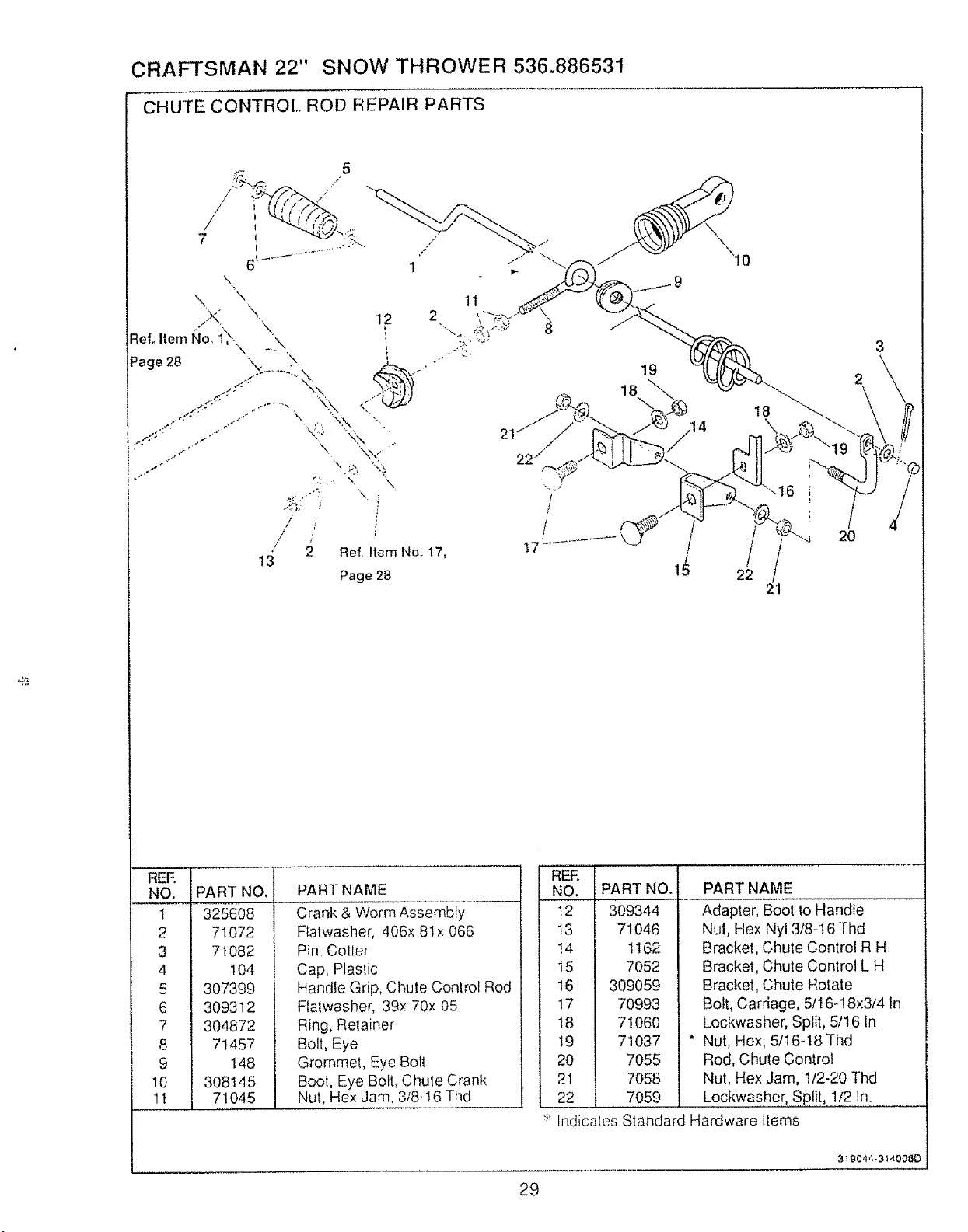
CRAFTSMAN 22" SNOW THROWER 536.886531
CHUTE CONTROL RODREPAIRPARTS
1t
19
18 \
15
18
22
21
RER
NO.
1
2
3
4
5
6
7
8
9
10
11
PART NO,
325608
71072
71082
104
307399
309312
304872
71457
148
308145
71045
PART NAME
Crank & Worm Assembly
Flatwasher, 406x 8lx 066
Pin. Cotter
Cap, Plaslic
Handle Grip, Chute Control Rod
Flatwasher, 39x 70x 05
Ring, Retainer
Bolt, Eye
Grommet, Eye Bolt
Bool, Eye Bolt, Chule Crank
Nut, Hex Jam. 3/8-I6 Thd
REE
NO.
t2
13
t4
!5
16
17
18
!9
20
21
22
PART NO.
309344
71046
1t62
7052
309059
70993
71060
71037
7055
7058
7059
PART NAME
Adapter, Boot to Handle
Nut, Hex Nyl 3/8-16 Thd
Bracket, Chute Control R H
Bracket, Chute Control L H
Bracket, Chute Rotate
Bolt, Carriage, 5/16-18x314 In
Lockwasher, Split, 5/16 In
Nut, Hex, 5/16-18 Thd
Rod, Chute Control
Nut, Hex Jam, 1/2-20 Thd
Lockwasher, Split, 1/2 In.
:::Indicales Standard Hardware Items
29
319044 -314008D
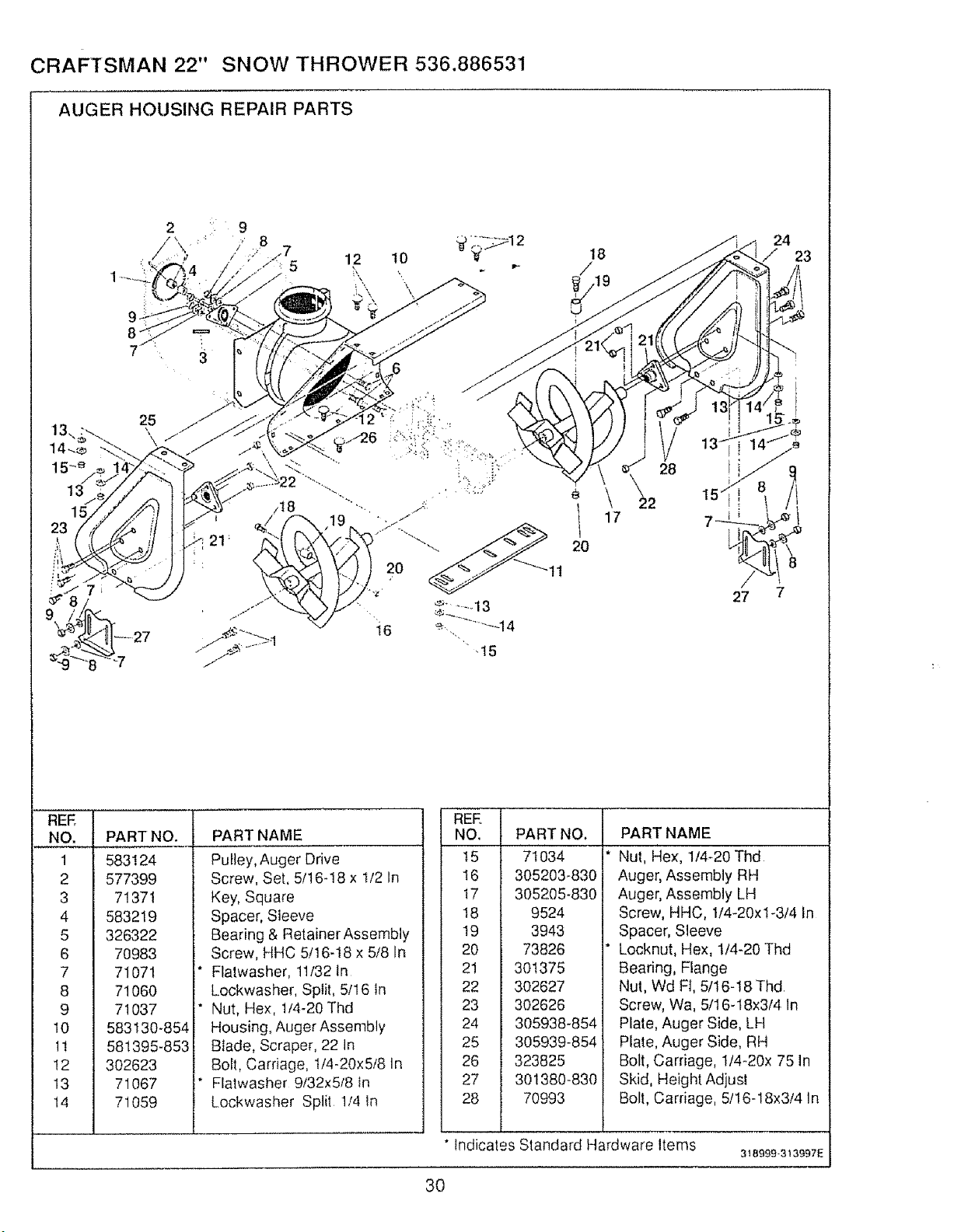
CRAFTSMAN 22" SNOW THROWER 536.886531
AUGER HOUSING REPAIR PARTS
REE
NO.
1
2
3
4
5
6
7
8
9
10
1t
12
13
14
PART NO.
583124
577399
71371
583219
326322
70983
71071
71060
71037
583130-854
581395-853
302623
71067
71059
PART NAME
Puiley, Auger Drive
Screw, Set, 5/t6-18 x I/2 In
Key, Square
Spacer, Steeve
Bearing & Retainer Assembly
Screw, HHC 5/16-18 x 5/8 In
Flatwasher, 11/32 In
Lockwasher, Splil, 5/16 in
Nut, Hex, 1/4-20 Thd
Housing, Auger Assembly
Blade, Scraper, 22 In
Bolt, Carriage, 1/4-20x5/8 In
Flatwasher 9/32x5/8 In
Lockwasher Split 1/4 in
18
i 17
20
28
22
24
23
REE
NO.
15
16
I7
18
19
2O
21
22
23
24
25
26
27
28
PART NO.
71034
305203-830
305205-830
9524
3943
73826
301375
302627
302626
305938-854
305939-854
323825
301380-830
70993
PART NAME
Nut, Hex, 1/4-20 Thd
Auger, Assembly RH
Auger, Assembly LH
Screw, HHC, 1/4-20xl-3/4 In
Spacer, Sleeve
Locknut, Hex, 1/4-20 Thd
Bearing, Flange
Nut, Wd Ft, 5/16-18 Thd
Screw, Wa, 5/16-18x3/4 In
Plate, Auger Side, LH
Plate, Auger Side, RH
Bolt, Carriage, 1/4-20x 75 In
Skid, Height Adjusl
Bolt, Carriage, 5/16-18x3/4 In
* Indicates Standard Hardware Items
318999-313997E
3O
CRAFTSMAN 22" SNOW THROWER 536.886531
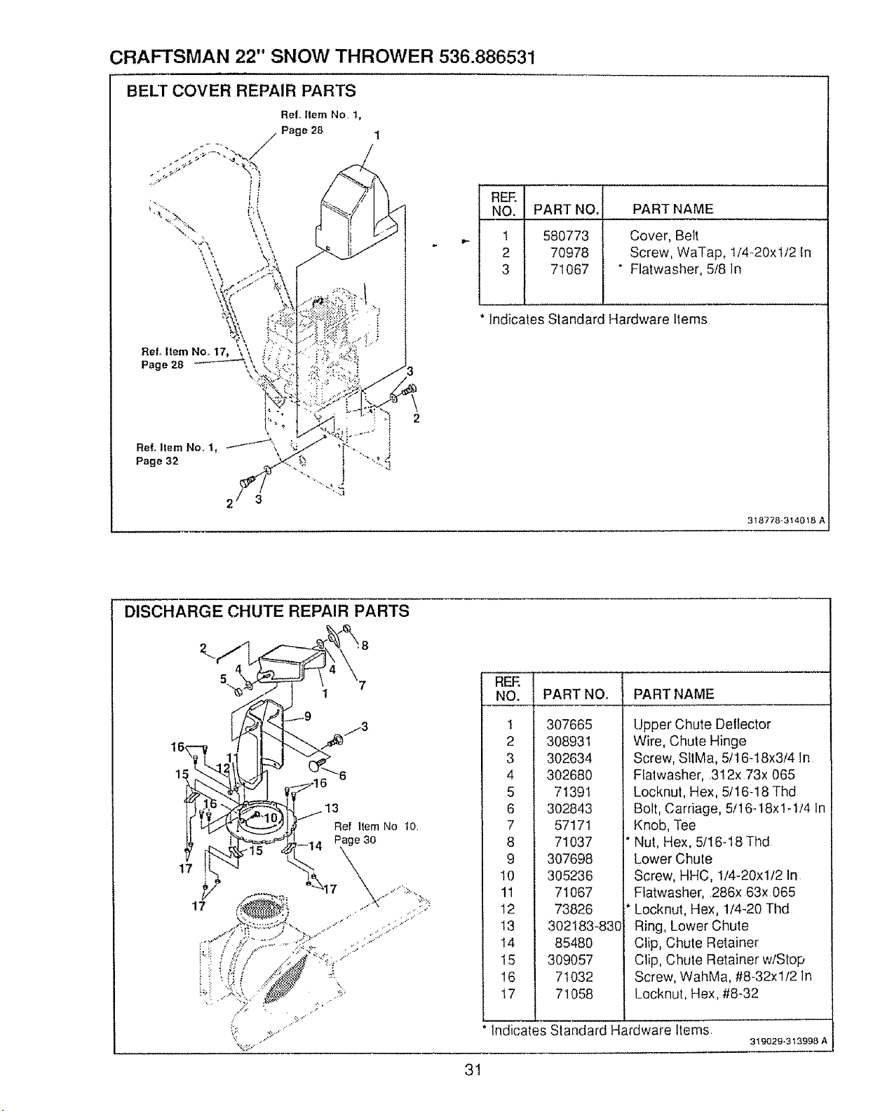
BELl" COVER REPAIR PARTS
i
R_:.i
__NO.
i
1
2
3
PART NO. PART NAME
580773 Cover, Belt
70978 Screw, WaTap, 1/4-20xl/2 In
71067 " Flatwasher, 5/8 in
Indicates Standard Hardware Items
318778,314018 A
DISCHARGE CHUTE REPAIR PARTS
t7
5
[
Ref Item No 10.
31
REF.
NO.
!
2
3
4
5
6
7
8
9
10
11
12
13
I4
15
16
17
PART NOo PART NAME
307665
308931
302634
302680
71391
302843
57171
71037
307698
305236
71067
73826
302183-830
85480
309057
71032
71058
Upper Chute Delfector
Wire, Chute Hinge
Screw, SIIMa, 5/16-18x3/4 In
Flatwasher, 312x 73x 065
Locknut, Hex, 5/t6-18 Thd
Bolt, Carriage, 5/16-18x1-1/4 tn
Knob, Tee
Nut, Hex, 5tl 6-18 Thd
Lower Chule
Screw, HHC, 1/4-20xl/2 In
Fiatwasher, 286x 63x 065
Locknut, Hex, 1/4-20 Thd
Ring, Lower Chute
Clip, Chute Retainer
Clip, Chute Retainer w/Stop
Screw, WahMa, #8-32xl/2 In
Locknut, Hex, #8-32
Indicates Standard Hardware Items
319029*313998 A
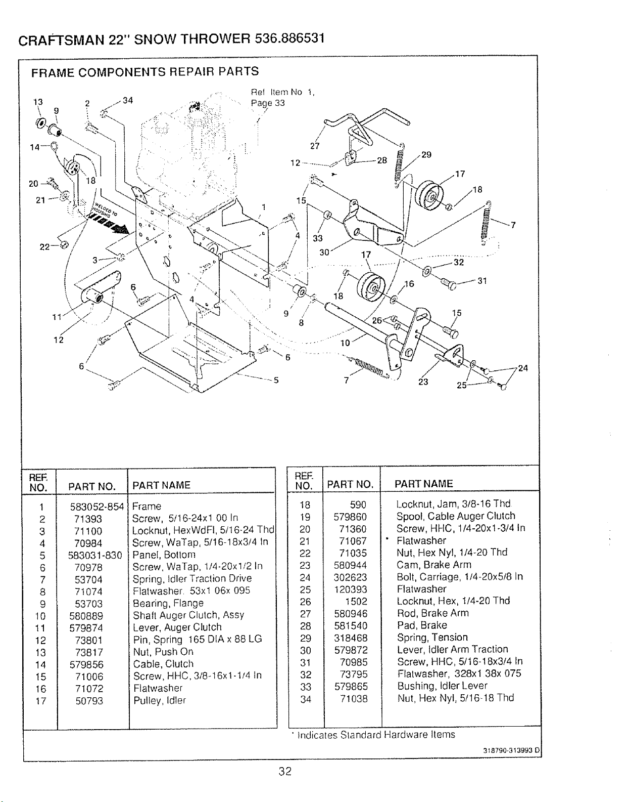
CRAFTSMAN 22" SNOW THROWER 536.886531
FRAME COMPONENTS REPAIR PARTS
¸,5¸'i¸¸¸
Ref Item No I,
Page 33
/
27
• t /
9
23
I
NO___:_.!
1 I
2 I
3
4 I
5
6
7
8
9
10
11
12
13
14
t5
!7
PART NO. PART NAME
583052-854
71393
71100
70984
583031-830
70978
53704
71074
53703
580889
Frame
Screw, 5/16-24xl 00 In
Locknut, HexWdFl, 5116-24 Thd
Screw, WaTap, 5/16-18x3/4 In
Panel, Bollom
Screw, WaTap, 114.20xl/2 In
Spring, Idler Traction Drive
Flalwasher 53xl 06x 095
Bearing, Flange
Shaft Auger Clutch, Assy
579874
73801
73817
579856
71006
71072
50793
Lever, Auger Clutch
Pin, Spring 165 DIA x 88 LG
Nut, Push On
Cable, Clutch
Screw, HHC, 3/8-16x 1-1/4 tn
Flatwasher
Putley, Idler
RER
NO.
18
19
2O
21
22
23
24
25
26
27
28
29
30
3l
32
33
34
PART NO,
590
579860
71360
71067
71035
58O944
302623
120393
1502
580946
581540
318468
579872
70985
73795
579865
71038
PART NAME
Locknut, Jam, 318-16 Thd
Spool, Cable Auger Clutch
Screw, HHC, I/4-20xl-3!4 In
Flatwasher
Nul, Hex Nyl, 1/4-20 Thd
Cam, Brake Arm
Bolt, Carriage, 1/4-20x5!8 In
Flalwasher
Locknut, Hex, tl4.20 Thd
Rod, Brake Arm
Pad, Brake
Spring, Tension
Lever, Idler Arm Traction
Screw, HHC, 5/16- ! 8x3/4 In
Flatwasher, 328xl 38x 075
Bushing, Idler Lever
Nut, Hex Nyl, 5/16q8 Thd
•tridicates Standard Hardware Items
32
318790-313993 O'
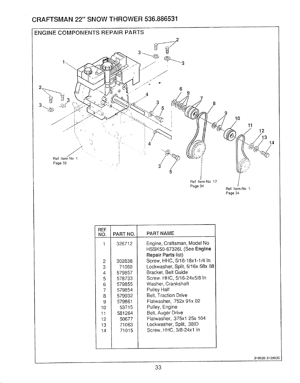
CRAFTSMAN 22" SNOW THROWER 536.886531
ENGINE COMPONENTS REPAIR PARTS
Re! Item!No 1
Page 32
5
9
8
9
t0
1t
Rel item No 1
Page 34
12
REE
NO.
t
2
3
4
5
6
7
8
9
10
11
12
I3
14
I
PART NO. PART NAME
326712
302636
71060
579857
578733
579855
579854
579932
579861
53715
581264
50677
71O63
71015
Engine, Craltsman, Model No
HSSK50-67326L (See Engine
Repair Parts list)
Screw, HHC, 5/ _6-18x1-1/4 In
Lockwasher, Split, 5/16x 58x 08
Bracket, Bef/Guide
Screw, HHC, 5116-24x5!8 tn
Washer, Crankshaft
Pulley Half
Belt, Traction Drive
Fiatwasher, ,752x 91x 02
Pulley, Engine
Be!l, Auger Drive
Flalwasher, 375x 1 25x, 104
Lockwasher, Split, 38tD
Screw, HHC, 3!8-24xl in
33
319026,3139920
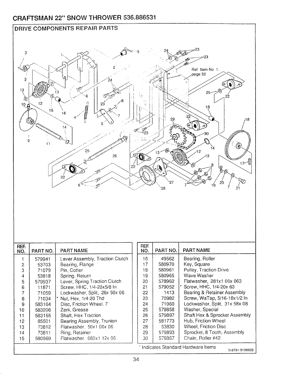
CRAFTSMAN 22" SNOW THROWER 536.886531
':DRIVE COMPONENTS REPAIR PARTS
13
1!
26
Ref item No 1,
,//.page 32
22
18
REF,
NO.
1
2
3
4
5
6
7
8
9
I0
tl
12
t3
14
_5 1
PART NO.
579941
53703
71079
53818
579937
11871
71059
71034
583164
583206
583155
85501
73812
73811
580969
PART NAME
Lever Assembly, Traction Clutch
Bearing, Flange
Pin, Cotter
Spring, Relurn
Lever, Spring Traction Clulch
Screw, HHC, 1/4-20x5/8 In
Lockwasher, Split, 26x 50x 06
Nul, Hex, 1/4-20 Thd
Disc, Friction Wheel, T'
Zerk, Grease
Shaft, Hex Traction
Bearing Assembly, Trunion
Flalwasher• 50xl 00x 06
Ring, Relainer
Flatwasher 680xl t2x 06
REE
NO PART NAME
t6
t7
18
19
20
21
22
23
24
25
26
27
28
29
3O
Indicates Standard Hardware Items
PART NO,
49562
580970
580961
580965
578962
579052
1413
70982
71060
579858
579897
581773
5383O
579893
579867
Bearing, Roller
Key, Square
Pulley, Traction Drive
Wave Washer
Flatwasher, 281xl 00x 063
Screw, HHC, 1t4-20x 63
Bearing & Retainer Assembly
Screw, WaTap, 5I!6-18xl/2 In
Lockwasher, Split, 31x 58x 08
Washer, Special
Shaft Hex & Sprocket Assembly
Hub, Friction Wheel
Wheel, Friction Disc
Sprocket, 8 Tooth, Assembly
Chain, Roller #42
318791-3139{358
34
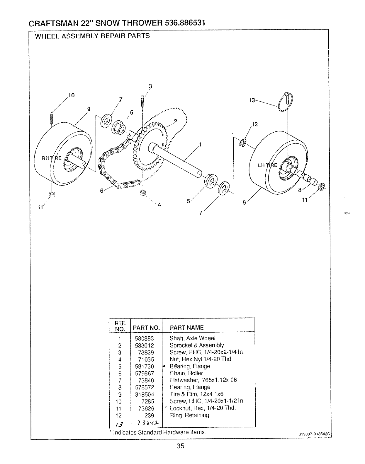
CRAFTSMAN 22" SNOW THROWER 536.886531
WHEEL ASSEMBLY REPAIR PARTS
REE
NO.
1
2
3
4
5
6
7
8
9
10
11
12
/J
PART NO.
580883
583012
73839
71O35
581730
579867
73840
578572
318504
7285
73826
239
PART NAME
Shaft, Axle Wheel
Sprocket & Assembly
Screw, HHC, 1/4-20x2-1/4 In
Nut, Hex Nyl 1/4-20 Thd
Bdaring, Flange
Chain, Roller
Ftatwasher, 765xl 12x 06
Bearing, Flange
Tire& Rim, 12x4 lx6
Screw, HHC, 1t4-20x1-1/2 In
Locknut, Hex, 1/4-20 Thd
Ring, Retaining
Indicates Standard Hardware Items
35
319037.3t8542C
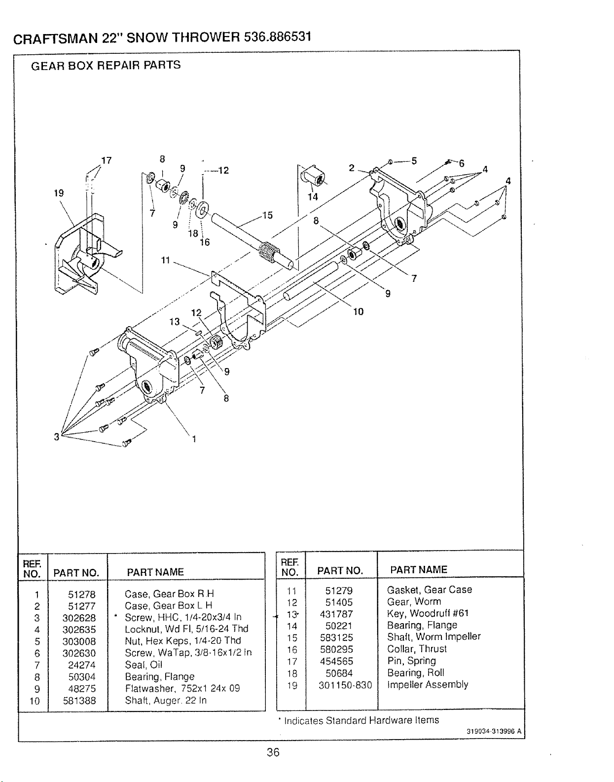
CRAFTSMAN 22" SNOW THROWER 536.886531
GEAR BOX REPAIR PARTS
19
\
!
9i i
18_
!6
11
10
/
/
\9
REF,
NO.
1
2
3
4
5
6
7
8
9
10
PART NO. PART NAME
51278
51277
302628
302635
303008
302630
24274
50304
48275
581388
Case, Gear Box RH
Case, Gear Box L H
Screw, HHC, 1/4-20x3/4 In
Locknut, Wd FI, 5/!6-24 Thd
Nut, Hex Keps, I/4-20 Thd
Screw, WaTap, 3/8q 6xl/2 In
Seal, Oil
Bearing, Flange
F1atwasher, 752xl 24x 09
Shaft, Auger 22 In
INO. PART NO.
tt
t2
13-
14
_5
171
18
• Indicates Standard Hardware ttems
51279
51405
431787
50221
583125
580295
454565
50684
301150-830
PART NAME
Gasket, Gear Case
Gear, Worm
Key, Woodruff #61
Bearing, F_ange
Shaft, Worm Impeller
Collar, Thrust
Pin, Spring
Bearing, Roll
Impeller Assembly
3190.343t3996 A
36
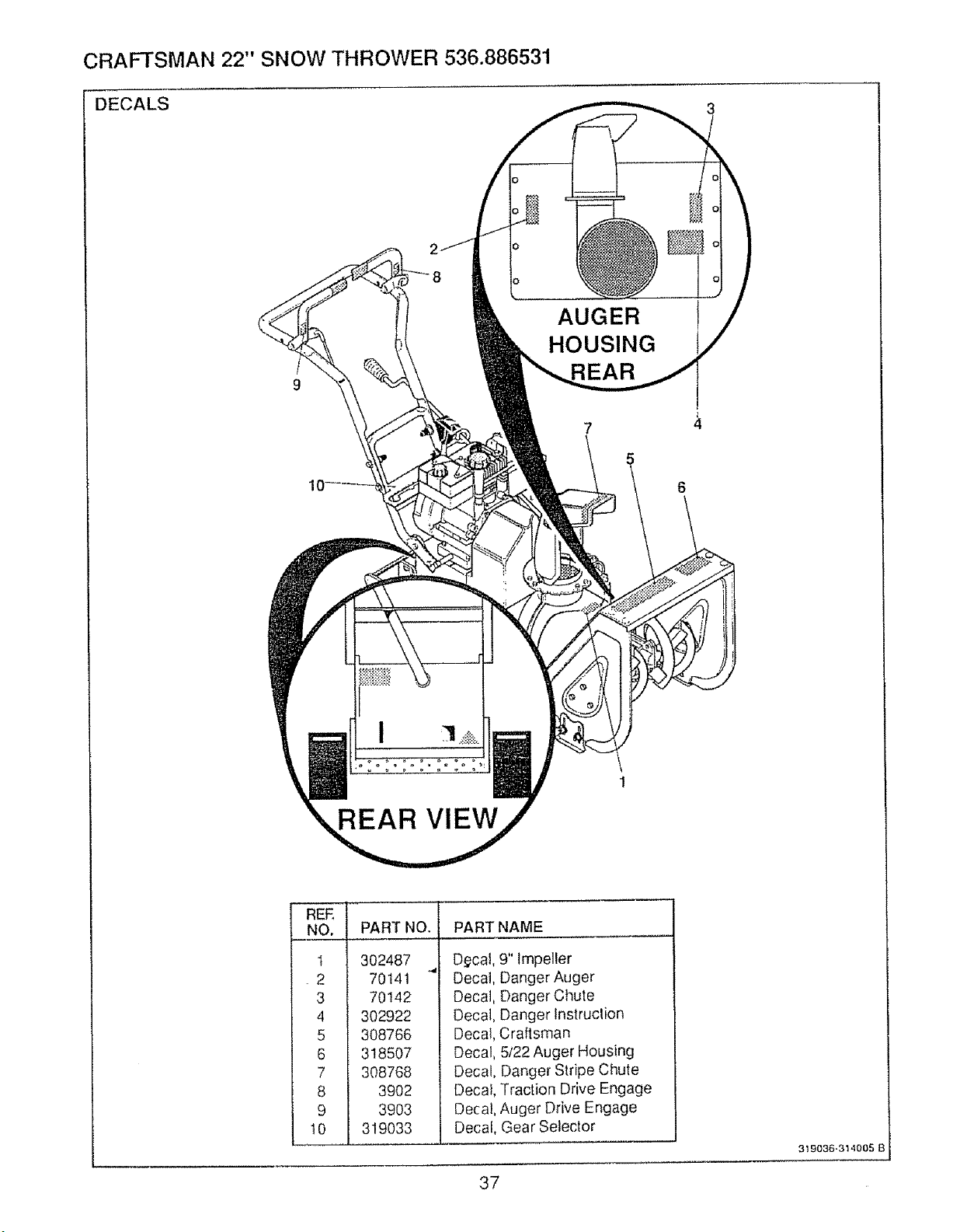
CRAFTSMAN 22" SNOW THROWER 536.886531
DECALS
REAR VIEW
AUGER
HOUSING
7
5
6
REE i
4 1
5
6 !
7
8 I
9
....t0 J
PART NO. PART NAME
302487
70141
70142
302922
308766
318507
308768
3902
39O3
319033
D_cal, 9" Impeller
Decal, Danger Auger
Decal, Danger Chute
Decal, Danger lnstruclion
Decal, Craftsman
Decal, 5/22 Auger Housing
Decal, Danger Stripe Chute
Decal, Traction Drive Engage
Decal, Auger Drive Engage
Decal, Gear Selector
3t9036.314005 B
37
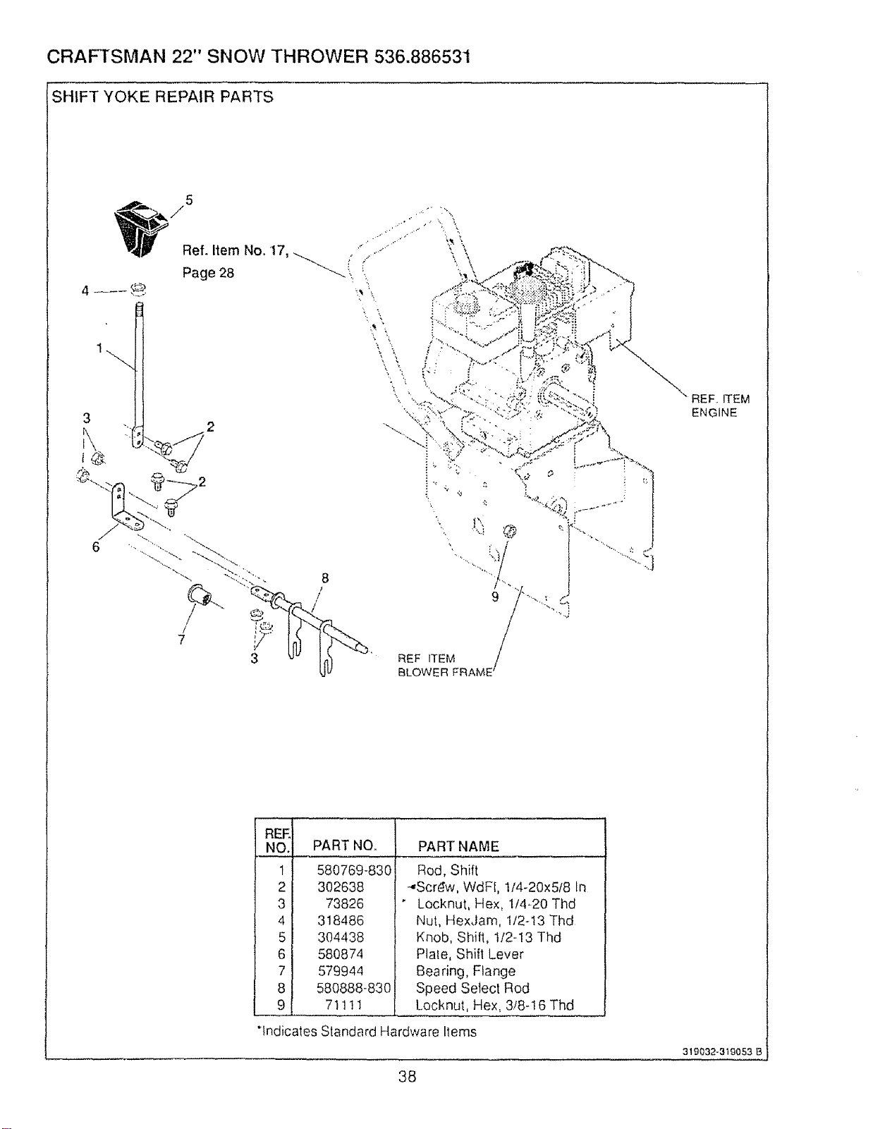
CRAFTSMAN 22" SNOW THROWER 536.886531
SHIFT YOKE REPAIR PARTS
5
Ref.ItemNo.17, i'/i.........." '
",',
Page
28
4 ----_
3
8
/
REF ITEM
BLOWER
REF, ITEM
ENGINE
REE
NO. PART NO.
1 580769-830
2 302638
3 73826
4 318486
5 304438
6 580874
7 579944
8 580888-83O
9 71111
PART NAME
Rod, Shift
-,,,Scrdw, WdFl, 1/4-20x5t8 In
" Locknut, Hex, 1/4-20 Thd
Nut, HexJam, I/2-!3 Thd
Knob, ShiN, t/2-13 Thd
Plale, Shift Lever
Bearing, Flange
Speed Setect Rod
Locknut, Hex, 3/8-I6 Thd
*R '
I dtcates Standard Hardware Items
38
319032-319053 B
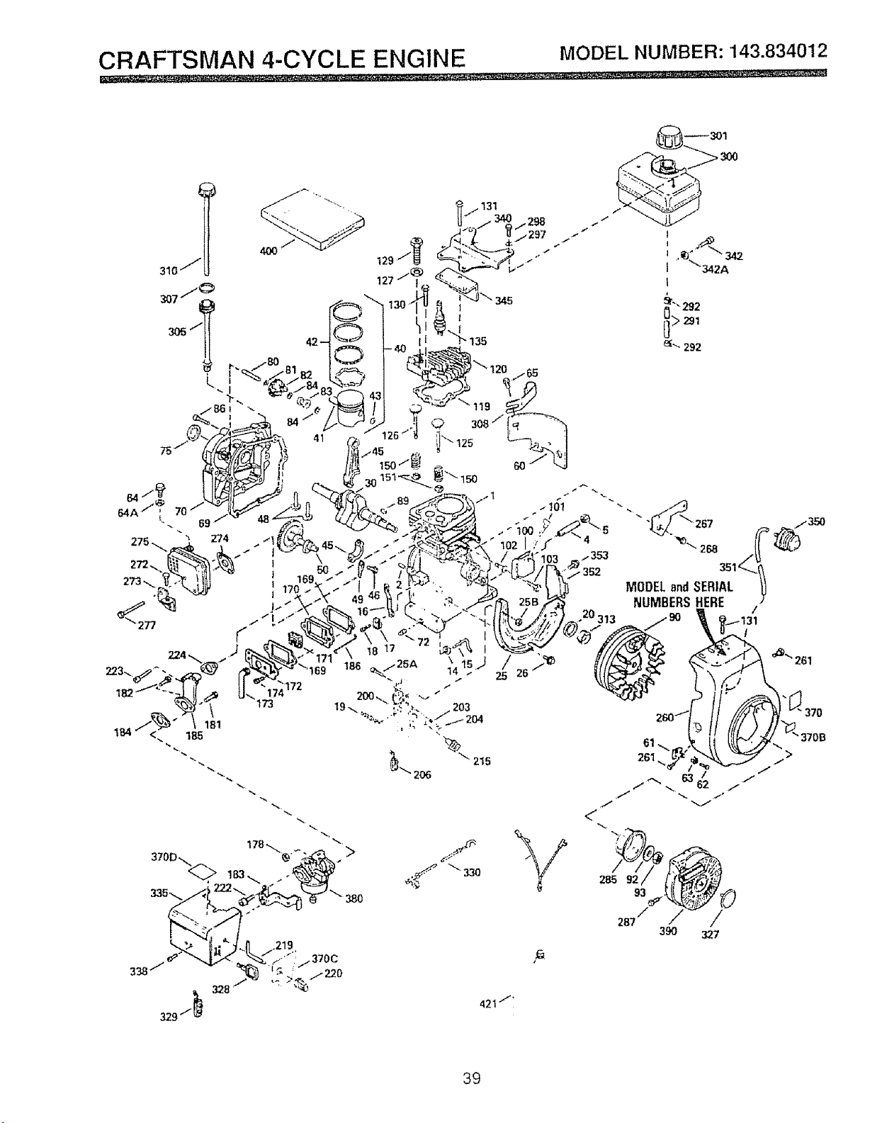
CRAFTSMAN 4-CYCLE ENGINE MODELNUMBER:143.834012
_301
172
173
38O
338/
328
219
_1370C
/220
421""
/,
390 327
39
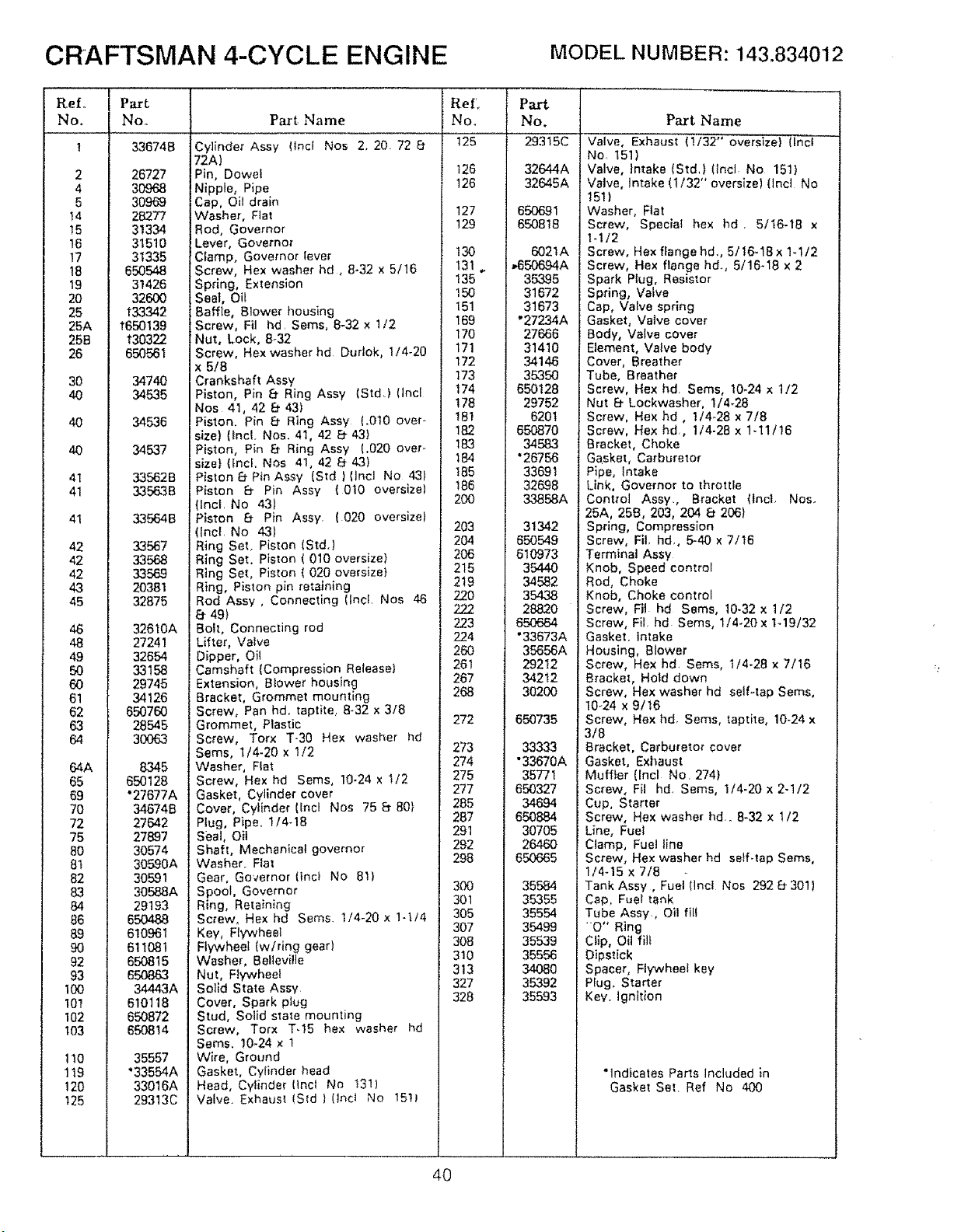
CRAFTSMAN 4-CYCLE ENGINE MODEL NUMBER: 143.834012
ReL
No.
2
4
5
t4
!5
16
17
18
19
2O
25
25A
25B
26
30
4O
4O
40
41
41
41
42
42
42
43
45
46
48
49
5O
6O
61
62
63
64
64A
65
69
70
72
75
8O
8t
82
83
84
86
89
9O
92
93
t00
101
102
;03
tI0
1t9
t20
!25
Part
No.
33674B
26727
3O968
30969
28277
31334
31510
31335
650548
31426
326O0
t33342
t65o139
t30322
650561
3474O
34535
34535
34537
33562B
33563B
33564B
33567
33568
33589
20381
32875
32610A
27241
32654
_158
29745
34126
65O76O
28545
30063
8345
650128
"27677A
34674B
27642
27897
30574
30590A
30591
30588A
29193
650488
610961
611081
650815
650863
34443A
610118
650872
650814
35557
"33554A
33016A
29313C
Part Name
Cylinder Assy (Incl Nos 2, 20. 72 8-
72A)
Pin, Dowet
Nipple, Pipe
Cap, Oil drain
Washer, Flat
Rod, Governor
Lever, Governor
Clamp, Governor lever
Screw, Hex washer hd, 8-32 x 5/16
Spring, Extension
Seat, Oil
Baffle, 8lower housing
Screw, Fil hd Sems, 8-32 x 1/2
Nut, Lock, 8.32
Screw, Hex washer hd Dudok, 1/4-20
x 5/8
Crankshaft Assy
Piston, Pin 8" Ring Assy (Std.) (Incl
Nos 41, 42 Et 43)
Piston. Pin 8" Ring Assy (.010 over-
size) (Incl. Nos. 41, 42 El- 43)
Piston, Pin 8- Ring Assy (.020 over..
size) (fncl. Nos 41, 42 8- 43)
Piston 8- Pin Assy {Std ) (lncl No 43)
Piston 8" Pin Assy (0t0 oversize)
i(Incl. No 43)
Piston 8 Pin Assy. (020 oversize)
(Inei. No 43)
Ring Set, Piston (Std.)
Ring Set. Piston ( 010 oversize)
Ring Set, Piston ( 020 oversize)
Ring, Piston pin retaining
Rod Assy , Connecting (tnct. Nos 46
8" 49)
Bolt, Connecting rod
Lifter, Valve
Dipper, Oit
Camshaft (Compression Release)
Extension, Blower housing
Bracket, Grommet mounting
Screw, Pan hd. taptite, 8-32 x 3/8
Grommet, Plastic
Screw, Torx T-30 Hex washer hd
Sems, 1/4-20 x 1/2
Washer, Flat
Screw, Hex hd Seres, 10-24 x I/2
Gasket, Cylinder cover
Cover, Cylinder (Incl Nos 75 8- 80}
Plug, Pipe. 1/4-18
Seal, Oil
Shaft, Mechanical governor
Washer, Flat
Gear, Governor (Inci No 8!)
Spool, Governer
Ring, Retaining
Screw, Hex hd Seres. t/4-20 x 1-l/4
Key, Flywheel
Flywheel (w/ring gearl
Washer, Belleville
Nut, Fiywheel
Sol_d State Assy
Cover, Spark plug
Stud, Solid state mounting
Screw, Torx Tq5 hex washer hd
Seres. 10-24 x 1
Wire, Ground
Gasket, Cylinder head
Head, Cytinder(lnct No 131)
Valve. Exhausl (Std } (lncI No 15D
ReL Part
No. No.
125 293t5C
126 32644A
126 32645A
127 650691
129 650818
6021A
,650694A
35395
31672
31673
"27234A
27666
31410
I 4146
35350
650128
29752
6201
650870
34583
"26756
33591
32698
33858A
203 31342
204 650649
206 510973
215 35440
219 34582
220 354,38
222 28820
223 650664
224 "33673A
260 35656A
261 29212
267 34212
268 30200
272 650735
273 33333
274 "33670A
275 35771
277 650327
285 34694
287 650884
291 30705
292 26460
298 650665
300 35584
301 36355
305 35564
307 35499
308 35539
310 35556
3!3 34080
327 35392
328 35593
130
t31 ,.
t35
t50
t51
169
170
171
172
173
174
178
181
182
183
184
185
186
200
Part Name
Valve, Exhaust (!/32" oversize) (Incl --
No 151)
Valve, Intake (Std,) (tncl No 151)
Valve, Intake (1/32" oversize) (lnd No
151}
Washer, Flat
Screw, Special hex hd. 5/16-18 x
l-!/2
Screw, Hex flange hd., 5/16-18 x 1-1/2
Screw, Hex flange hd., 5/16-18 x 2
Spark Plug, Resistor
Spring, Valve
Cap, Valve spring
Gasket, Valve cover
Body, Valve cover
Element, VMve body
Cover, Breather
Tube, Breather
Screw, Hex hd. Seres, 10-24 x 1/2
Nut 8- Lockwasher, I/4-28
Screw, Hex hd, I/4-28 x 7/8
Screw, Hex hal, 1/4.28 x 1-11/16
Bracket, Choke
Gasket, Carburetor
Pipe, Intake
Link, Governor to throttle
Control Assy., Bracket (lncL Nos..
25A, 25B, 203, 204 _ 206)
Spring, Compression
Screw, Fil. hal, 5-40 x 7/t6
Terminal Assy
Knob, Speed control
Rod, Choke
Knob, Choke control
Screw, Fil hd Sems, 10-32 x 1/2
Screw, FiL hd Sems, 1/4.20x lq9/32
Gasket. Intake
Housing, Blower
Screw, Hex hd. Seres, t/4-28 x 7/16
Bracket, Hold down
Screw, Hex washer hd self-tap Seres,
10_24 x 9/t6
Screw, Hex hd Seres, tapthe, 10-24 x
3/8
Bracket, Carburetor cover
Gasket, Exhaust
Muffler {lncl No 274)
Screw, Fil hd. Seres, I/4-20 x 2-1/2
Cup, Starter
Screw, Hex washer hd.. 8-32 x 1/2
Line, Fuel
Clamp, Fuel line
Screw, Hex washer hd serf-tap Sems,
1/4-15 x 7/8
Tank Assy, Fuel (Incl Nos 292 8- 301)
Cap, Fuel tank
Tube Assy, Oii fill
"O" Ring
Clip, Oil flit
Dipstick
Spacer, Flywheel key
PIug. Starter
Key. ignition
"Indicates Parts Included in
Gasket SaL Ref No 400
40
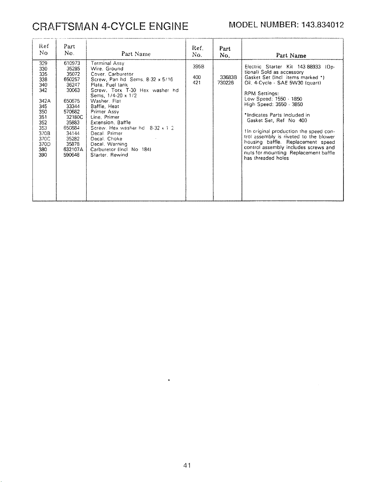
CRAFTSMAN 4-CYCL.E ENGINE MODEL NUMBER:143.834012
Ref Part Part
No No, No. Part Name
329
330
335
338
340
342
342A
345
350
351
352
353
370B
370C
370D
380
390
610973
35285
35072
650257
36247
30063
650675
33344
570682
32180C
35883
650884
34144
35282
35878
632107A
59O648
Part Name
Terminal Assy
Wire. Ground
Cover, CarbureTor
Screw, Pan hd Seres. 8-32 x5/16
Plate. Fuel tank
Screw. Torx T-30 Hex washer hd
Seres, t/4-20 x t/2
Washer. F]a_
Baffie, Hea!
Primer Assy
Line. Primer
Extension. Baffle
Screw, Hex washe_ I-_d 8.32 x 1 Z
Decal Primer
Decal, Choke
Decal. Warning
Carburetor (Incl No 184}
Starter. Rewind
Ref..
Noo
3958
400
421
33683 B
730226
Electric Statler Kit 14388.933 (Op-
tional) Sold as accessory
Gasket Set (tncl items marked *)
Oil. 4-Cycle - SAE 5W30 (quart}
RPM Settings:
Low Speed; !550 - 1850
High Speed: 3550 - ,3850
"Indicates Parts Included in
Gasket SeT, Ref No 400
tin original production the speed con-
trol assembly is riveted to the blower
housing baffle, Replacement speed
control assembly includes screws and
nuts for mounting Replacement baffle
l_as threaded holes
41
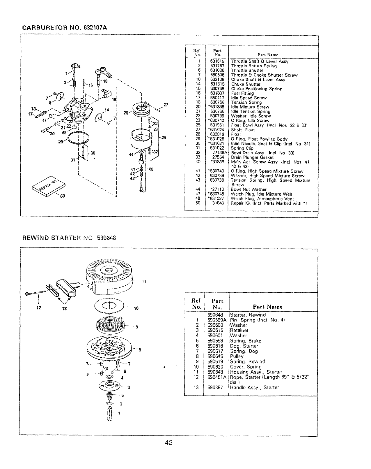
CARBURETOR NO. 632t07A
-j.
I 2! 631757!
I 6| 63_036I
] 71 650506 J
! _o| 6321081
i _4| 63_B15 ]
[ _5| 630735 1
! _6! e3_B07 ]
! _a/ _o7_ I
I 20| .e3_83at
I 22 | 830739 l
I 23 | "630740 1
I 251 63t95_ j
[ 27 | "631024 t
[ 2B|. &32019 I
I 29 |"'631028 J
l 30| "_021 !
i 3_| _o22 |
i 32 | 27136A l
33 | 27554 t
i _| -3_B39I
I _, | ._o74o !
42 | 830739 I
' _[ 63o7* I
47 | '630748 J
Part Name
Throttle Shaft 8" Lever Assy
Throttle Return Spring
Throme Shutter
ThmtHe Et Choke Shutter Screw
Choke Shaft 8 Lever A_y
Choke Shutter
Choke Poeitionlng Spring
Fuel Fitting
Idle Speed Screw
Tension Spring
IdleMixture Screw
idle Tension Spdng
Washer, Idle Screw
O Ring, Idle Screw
FIoat Bow] Assy (lnci Nos 32 E_ ,3,3)
Shah Float
Flea1
O Ring, Roar Bow] to Body
Inlet Needle, Seat _t Clip {Inci No 311
Spring Clip
Bowl Drain Assy {incl NO 33)
Drain Plunger Gasket
Main Adj Screw Assy tlncl Nos 41,
42 8' 43}
0 Ring, High Speed Mixture Screw
Washer, High Speed Mixture Screw
Tension Spring, High Speed Mixture
Screw
Bowi Nut Washer
Welch Plug, idle Mixture Well
Welch Plug. Atmospheric Vent
Repair Kit {Incl Parts Marked with *}
REWIND STARTER NO 590648
12 13 10
....... 9
4
11
'"'""'Rel, Part
} No, I No,
l 159o_
l 1 t 590599A
l 2 l 59o_0
] 3 I 590615
l 4 [ 590601
I 5 ) 590598
/ 6 f _oe_
/ 7 1 69o6_7
I a I 590_45
| 9 I 590619
J 10 / 590620
) _ 1590643
l t2 t 590451A
Part Name
|Starter, Rewind
Pin, Spring (Incl No 4)
Washer
Retainer
Washer
Spring, Brake
Dog, Starter
Spring. bog
Pulley
Spring, Rewind
Cover. Spring
Housing Assy, Starter
Rope, Starter (Length 69" B 5/32"
dia }
Handle Assy , Starter
42

NOTES
43
OWNER'S
ANUAL
MODEL NO.
536.886531
HOW TO ORDER
REPAIR PARTS
C
5 HORSEPOWER
22" DUAL STAGE
SNOW THROWER
Optional e_ectric start
®
Each SNOW THROWER has its own MODEL
NUMBER found on the engine mount frame
Each ENGINE has its own MODEL NUMBER
found on the BLOWER HOUSING
Always mention these MODEL NUMBERS when
requesting service or Repair Parts for your SNOW
THROWER
All parls may be ordered through Sears, Roebuck
and Company Service Centers and most Retail
Stores
WHEN ORDERING REPAIR PARTS, ALWAYS
GIVE THE FOLLOWING INFORMATION:
' PRODUCT - "SNOW THROWER"
• MODEL NUMBER - 536.,886530
* ENGINE MODEL NUMBER - 1438340t2
* PART NUMBER
* PART DESCRIPTION
"Your Sears merchandise has added value when you
consider that Sears has service units nationwide staffed
wilh Sears trained technicians Professional technicians
specifically trained on Sears products, having the parts,
tools and equipment to insure that we meet our pledge
to you_ we service what we sell -
SEARS, ROEBUCK AND COn, Hoffman Estates, IL 60195
325951 08/05192 Printed in U S A