
(L)VRCTLDDWSC*A, *2A VRCTLRDDWSC*A, *2A , (L)VRCTL8WSC*1A, *2A, *3A, VRCTLR8WSC*1A, *2A, *3A
Page 1
98982C (Rev. T - 01/19)
Model VRCTL8WS
Model VRCTLR8WS
VRC8TLWS™ Series Water Coolers with ezH2O
®
Bottle Filling Stations
Refrigeradores de agua serie VRCTL8WS™ con estaciones de llenado de botellas ezH2O
®
Les refroidisseurs d’eau de la série VRCTL8WS™ avec des stations de remplissage de bouteilles ezH2O
®
INSTALLATION and USE MANUAL

(L)VRCTLDDWSC*A, *2A VRCTLRDDWSC*A, *2A , (L)VRCTL8WSC*1A, *2A, *3A, VRCTLR8WSC*1A, *2A, *3A
Page 2
98982C (Rev. T - 01/19)
(L)VRC8WS Bottle Fillers are among the easiest to install on the market today. To insure you install
these models easily and correctly, PLEASE READ THESE SIMPLE INSTRUCTIONS BEFORE
STARTING THE INSTALLATION. CHECK YOUR INSTALLATION FOR COMPLIANCE WITH
PLUMBING, ELECTRICAL, AND OTHER APPLICABLE CODES. After installation, leave these
instructions with the Fountain for future reference.
(L)VRC8WS rellenos de botella están entre los más fáciles de instalar en el mercado hoy en día. Para
asegurar que instale estos modelos fácilmente y correctamente, POR FAVOR LEA ESTAS SIMPLES
INSTRUCCIONES ANTES DE INICIAR LA INSTALACIÓN. COMPRUEBE SU INSTALACIÓN PARA
CUMPLIR CON LA PLOMERÍA, ELÉCTRICO, Y OTROS CÓDIGOS APLICABLES. Después de la
instalación, deje estas instrucciones con la fuente para futuras referencias.
Les garnitures de bouteilles (L)VRC8WS sont parmi les plus faciles à installer sur le marché
aujourd’hui. Pour vous assurer d’installer ces modèles facilement et correctement, VEUILLEZ LIRE
CES INSTRUCTIONS SIMPLES AVANT DE DÉMARRER L’INSTALLATION. VÉRIFIEZ VOTRE
INSTALLATION POUR CONFORMITÉ AVEC PLOMBERIE, ÉLECTRIQUE ET AUTRES CODES
APPLICABLES. Après l’installation, laissez ces instructions avec la fontaine pour référence ultérieure.
IMPORTANT! INSTALLER PLEASE NOTE
THE GROUNDING OF ELECTRICAL EQUIPMENT SUCH AS TELEPHONE, COMPUTERS, ETC. TO WATER LINES IS A COMMON
PROCEDURE. THIS GROUNDING MAY BE IN THE BUILDING OR MAY OCCUR AWAY FROM THE BUILDING. THIS GROUNDING CAN
CAUSE ELECTRICAL FEEDBACK INTO A FOUNTAIN, CREATING AN ELECTROLYSIS WHICH CAUSES A METALLIC TASTE OR AN
INCREASE IN THE METAL CONTENT OF THE WATER. THIS CONDITION IS AVOIDABLE BY USING THE PROPER MATERIALS AS
INDICATED. ANY DRAIN FITTINGS PROVIDED BY THE INSTALLER SHOULD BE MADE OF PLASTIC TO ELECTRICALLY ISOLATE THE
FOUNTAIN FROM THE BUILDING PLUMBING SYSTEM. WE SUGGEST THAT THE BOTTLE FILLING STATION AND WATER COOLER
BE PROTECTED BY A GROUND FAULT CIRCUIT INTERRUPTER (GFCI).
LA PUESTA A TIERRA DE EQUIPOS ELÉCTRICOS COMO TELÉFONO, ORDENADORES, ETC. A LAS LÍNEAS DE AGUA ES UN
PROCEDIMIENTO COMÚN. ESTA PUESTA A TIERRA PUEDE ESTAR EN EL EDIFICIO O PUEDE OCURRIR LEJOS DEL EDIFICIO.
ESTA PUESTA A TIERRA PUEDE CAUSAR REACCIÓN ELECTRICA EN UNA FUENTE, CREANDO UN ELECTRÓLISIS QUE CAUSA
UN GUSTO METÁLICO O UN AUMENTO EN EL CONTENIDO METÁLICO DEL AGUA. ESTA CONDICIÓN ES EVITABLE UTILIZANDO
LOS MATERIALES APROPIADOS COMO SE INDICA. CUALQUIER ACOPLAMIENTO DE DRENAJE PROPORCIONADO POR EL
INSTALADOR DEBE SER HECHO DE PLÁSTICO PARA AISLAR ELÉCTRICAMENTE LA FUENTE DEL SISTEMA DE PLOMERÍA DE
CONSTRUCCIÓN. SUGERIMOS QUE LA ESTACIÓN DE LLENADO DE BOTELLAS Y EL REFRIGERADOR DE AGUA ESTÉ PROTEGIDA
POR UN INTERRUPTOR DE CIRCUITO DE FALLA DE TIERRA (GFCI).
LA MISE À LA TERRE D’ÉQUIPEMENT ÉLECTRIQUE COMME TELEPHONE, COMPUTERS, ETC. AUX LIGNES D’EAU EST UNE
PROCÉDURE COMMUNE. CETTE MISE À LA TERRE PEUT ETRE DANS LE BÂTIMENT OU PEUT DÉCOURIR LE BÂTIMENT. CETTE
MISE À LA TERRE PEUT CAQUER UN RÉTROACEMENT ÉLECTRIQUE DANS UNE FONTAINE, CRÉANT UNE ÉLECTROLYSE
QUI CAUSE UN GOUT MÉTALLIQUE OU UNE AUGMENTATION DU CONTENU MÉTALLIQUE DE L’EAU. CETTE CONDITION EST
ÉVALUABLE EN UTILISANT LES MATÉRIELS PROPRES COMME INDIQUÉS. TOUS LES RACCORDS DE SERRAGE FOURNIS PAR
L’INSTALLATEUR DEVRAIENT ÊTRE FABRIQUES EN PLASTIQUE POUR ISOLER À L’ÉLECTRICITÉ LA FONTAINE DU SYSTÈME DE
PLOMBERIE DU BÂTIMENT. Nous souhaitons que la station de remplissage de la bouteille et le refroidisseur d’eau soient protégés par un
INTERRUPTEUR DE CIRCUIT DE DÉFAUT DE TERRE (GFCI).
TOOLS REQUIRED
BUT NOT PROVIDED:
SAFETY GLASSES
GLOVES
ELECTRIC DRILL
3/4” WRENCH OR CRESCENT WRENCH
UTILITY KNIFE
TAPE MEASURE
PENCIL
CENTER PUNCH
1/2” SOCKET & RATCHET WRENCH
5/32” ALLEN WRENCH
HERRAMIENTAS NECESARIAS
PERO NO SUMINISTRADO:
LENTES DE SEGURIDAD
GUANTES
TALADRO ELÉCTRICO
3/4“ LLAVE AJUSTABLE
CUCHILLO PARA USO GENERAL
CINTA MÉTRICA
LÁPIZ
SACADOR DE CENTRO
TOMA DE 1/2” Y LLAVE DE TRINQUETE
5/32” LLAVE ALLEN
OUTILS NÉCESSAIRES
MAIS NON FOURNI:
LUNETTES DE PROTECTION
GANTS
PERCEUSE ÉLECTRIQUE
3/4” CLÉ À MOLETTE
COUTEAU UTILITAIRE
RUBAN À MESURER
CRAYON
OUTIL CENTER PUNCH
DOUILLE 1/2”& CLÉ À CLIQUET
5/32” CLÉ ALLEN
(L)VRCTLDDWSC*A, *2A VRCTLRDDWSC*A, *2A , (L)VRCTL8WSC*1A, *2A, *3A, VRCTLR8WSC*1A, *2A, *3A
Page 3
98982C (Rev. T - 01/19)
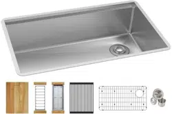
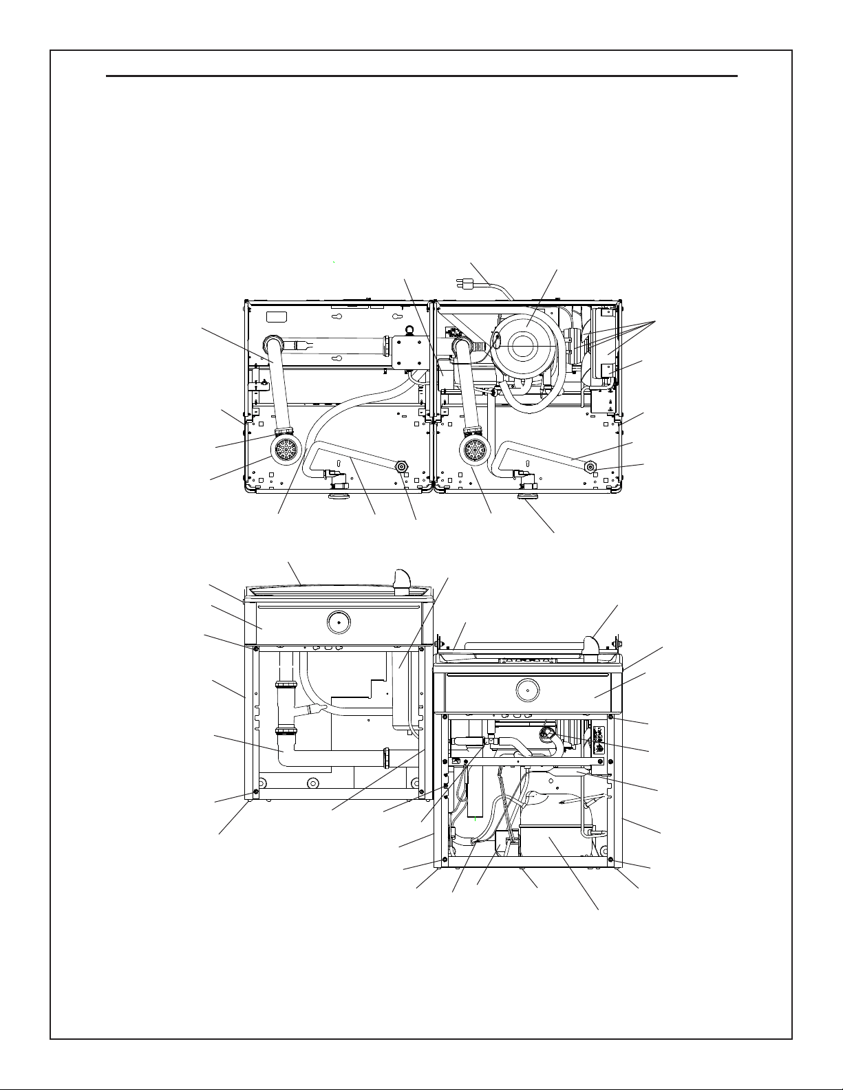
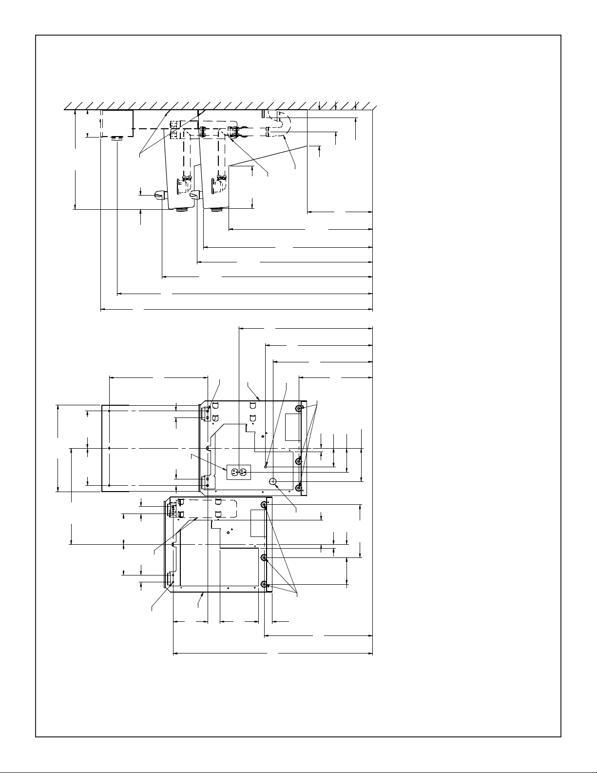
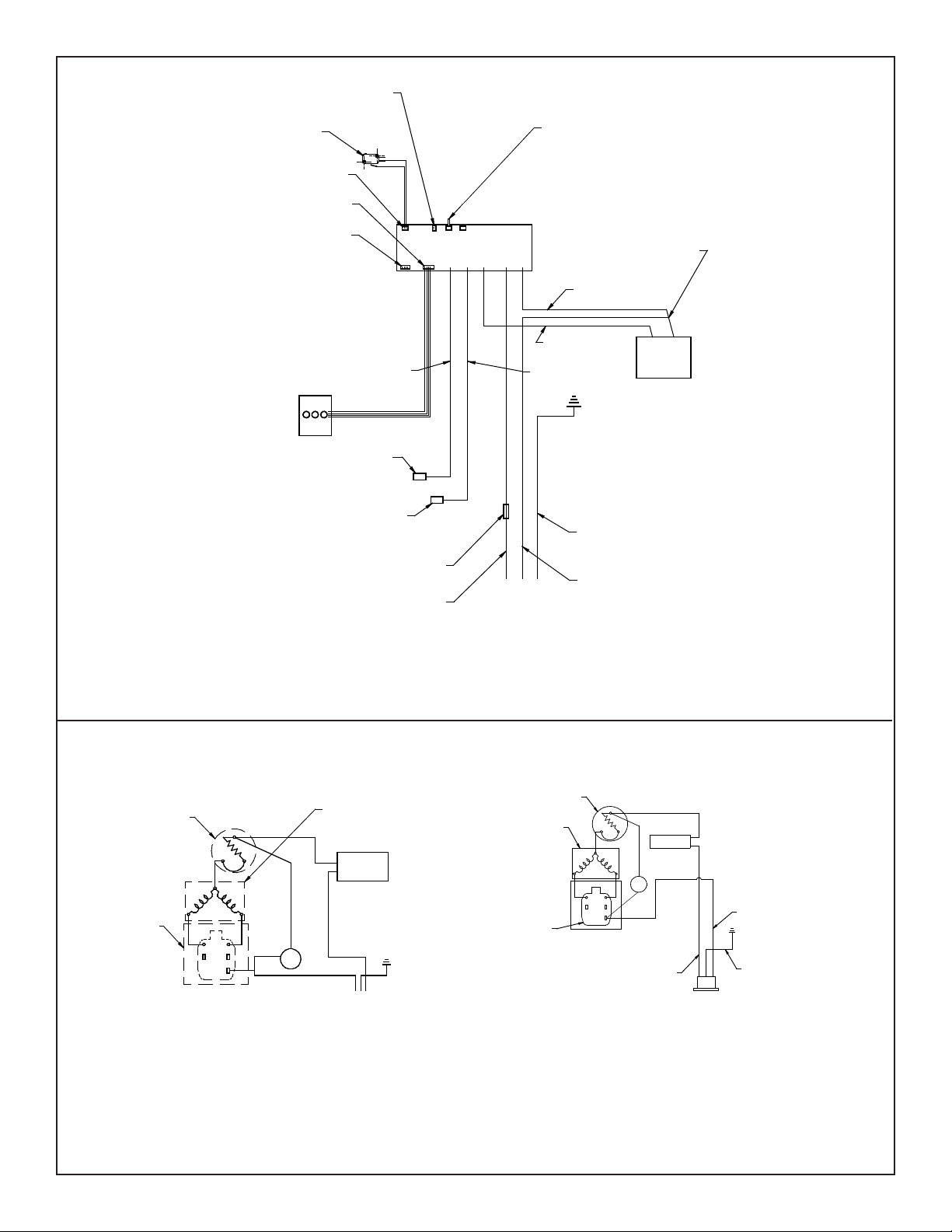
NOTE: Non-refrigerated units do not include all electrical and refrigeration components
shown above.
Other components and rough-in are the same as shown.
NOTA: Las unidades no frigoricadas no incluyen todos los componentes eléctricos y de
la refrigeración demostrados arriba. Otros componentes y a’spero-en son iguales según
lo demostrado.
NOTE: Les unités non frigoriées n’incluent pas tous les composants électriques et de
réfrigération montrés ci-dessus. D’autres composants et rugueux-dans sont identiques
que montrés.
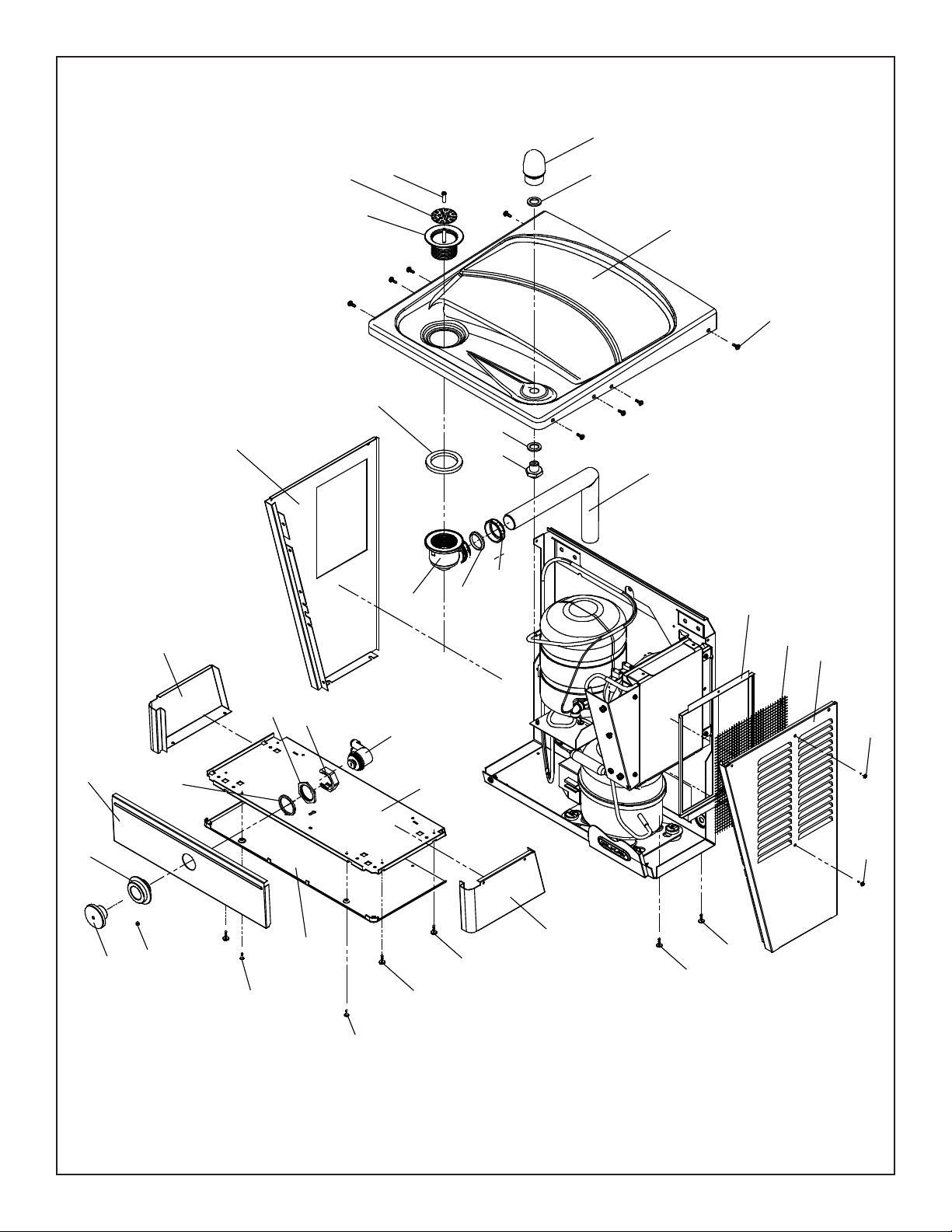
20
16
23
1
6
3
37 (TL)
38 (TLR)
15
23
27
9, 30
FIG. 1
LVRCTL8 SHOWN
Note: Danger! Electric shock hazard. Disconnect power before servicing unit.
Nota: peligro! Peligro de descarga eléctrica. Desconecte antes de reparar la unidad.
Remarque : Danger ! Risque d'électrocution. Débrancher avant de réparer l'appareil.
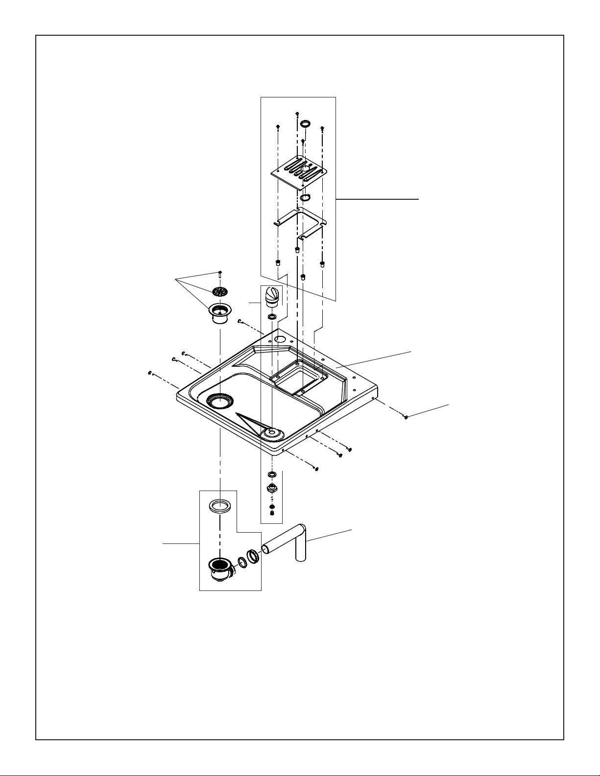
10
22
4
9, 30
1
66
25a
33
21
36
29
13
25b
See Fig. 8
See Fig.11
33
21
14
19
11
35
13
11,12
13
17
2
21
21
39 (TL)
40 (TLR)
8
Optional Filter Shown
Pictured is unit only without bottle ller.
En la foto, la unidad sólo sin relleno botella.
Sur la photo, est une unité seulement sans remplissage de la bouteille.
Uses HFC-134A refrigerant
Usa refrigerante HFC-134A
Utilise du uide frigorigéne HFC-134A
21
13
13
(L)VRCTLDDWSC*A, *2A VRCTLRDDWSC*A, *2A , (L)VRCTL8WSC*1A, *2A, *3A, VRCTLR8WSC*1A, *2A, *3A
Page 4
98982C (Rev. T - 01/19)
LEGEND/LEYENDA/LÉGENDE
A = RECOMMENDED WATER SUPPLY LOCATION 3/8 O.D. UNPLATED COPPER TUBE CONNECT STUB WITH SHUT OFF (BY OTHERS) 3 IN. (76mm) MAXIMUM OUT FROM WALL
La UBICACION 3/8 O RECOMENDADA de ABASTECIMIENTO DE AGUA. D. El TUBO del COBRE de UNPLATED CONECTA TALONARIO CON APAGO (POR OTROS) 3 en. (76 Mm) el MAXIMO FUERA DE
PARED
L’O.D de 3/8 d’EMPLACEMENT DE PROVISION D’EAU RECOMMANDE. LE TUBE DE CUIVRE DE UNPLATED CONNECTE STUB AVEC ETEINT (PAR LES AUTRES) 3 dans. (76 mm) le MAXIMUM HORS DU
MUR
B = RECOMMENDED LOCATION FOR WASTE OUTLET 1-1/2” O.D. DRAIN STUB 2 IN. OUT FROM WALL
UBICACIÓN RECOMENDADA PARA EL DRENAJE DE SALIDA DE AGUA, DE 1-1/2” DE DIÁMETRO. El TALONARIO 2 FUERA DE PARED
EMPLACEMENT RECOMMANDÉ POUR LE DRAIN DE D.E. 1-1/2” DE SORTIE D’EAU. STUB 2 HORS DU MUR
C = 1-1/2 TRAP NOT FURNISHED
PURGADOR DE 1-1/2 NO PROPORCIONADO
SIPHON 1-1/2 NON FOURNI
D = ELECTRICAL SUPPLY (3) WIRE RECESSED BOX
CAJA RECESIVA DE ALAMBRES (3) DE SUMINISTRO ELÉCTRICO
BOÎTE ENCASTRÉE D’ALIMENTATION ÉLECTRIQUE (3) FILS
E = INSURE PROPER VENTILATION BY MAINTAINING 6” (152 mm) (MIN.) CLEARANCE FROM CABINET LOUVERS TO WALL.
ASEGURE UNA VENTILACIÓN ADECUADA MANTENIENDO UN ESPACIO E 6” (152 mm) (MÍN.) DE HOLGURA ENTRE LA REJILLA DE VENTILACIÓN DEL MUEBLE Y LA PARED
ASSUREZ-VOUS UNE BONNE VENTILATION EN GARDANT 6” (152 mm) (MIN.) ENTRE LES ÉVENTS DE L’ENCEINTE ET LE MUR.
F = 7/16 BOLT HOLES FOR FASTENING UNIT TO WALL
AGUJEROS DE LAS TUERCAS DE 7/16 PARA SUJETAR LA UNIDAD A LA PARED
TROUS D’ÉCROUS 7/16 POUR FIXER L’APPAREIL AU MUR
**NEW INSTALLATIONS MUST USE GROUND FAULT CIRCUIT INTERRUPTER (GFCI)
**Las nuevas instalaciones deben utilizar el interruptor de circuito de tierra de la avería (GFCI)
**Les nouvelles installations doivent employer l’interrupteur de circuit moulu de défaut (GFCI)
FIG. 2
(L)VRCTL8
* ADA REQUIREMENT
* REQUISITO DE A.D.A.
* EXIGENCE ADA
OPTIONAL
* REDUCE HEIGHT BY 3” FOR INSTALLATION OF CHILDREN’S ADA COOLER
13 7/8
352mm
18 3/4
476mm
20 1/8
511mm
25 1/8
638mm
11/16
18mm
3 1/2
89mm
4 1/2
114mm
6 1/4
159mm
5
127mm
2 1/2
63mm
10
254mm
20 3/8
518mm
2 9/16
65mm
7 1/4
185mm
3/4
18mm
4 1/2
116mm
F
A
E
D
B
F
E
18 1/2
470mm
1 1/4
32mm
1 1/4
32mm
7
178mm
16 5/16
414mm
18 1/16
459mm
1 3/8
34mm
5 3/4
146mm
5 3/4
146mm
1 3/8
35mm
37 1/2
953mm
6 1/2
165mm
O
5/16
8mm
HOLES (5)
1/4" x 1/2"
(6mm x 13mm)
OBROUND HOLES (5)
FINISHED FLOOR
FILTER
C
8
203mm
6 3/4
172mm
12 5/16
312mm
4 1/8
105mm
27
686mm
ADA
REQUIREMENT
31 13/16
808mm
RIM HEIGHT
33
838mm
ORIFICE
HEIGHT
39 9/16
1005mm
ORIFICE
HEIGHT
51 1/8
1299mm
HANGER
BRACKET
48
1220mm
2 5/8
66mm
1 1/2
37mm
18 11/16
474mm
FILTER
FINISHED FLOOR
7
178mm
5 1/8
131mm
*
*
(L)VRCTLDDWSC*A, *2A VRCTLRDDWSC*A, *2A , (L)VRCTL8WSC*1A, *2A, *3A, VRCTLR8WSC*1A, *2A, *3A
Page 5
98982C (Rev. T - 01/19)
C
L
C
L
FINISHED FLOOR
F
A
E
D
B
F
E
C
6-3/4"
172mm
4-1/8"
105mm
13-7/8"
352mm
6-1/4"
159mm
11/16"
18mm
4-9/16"
116mm
2-9/16"
65mm
18-3/4"
476mm
7-1/4"
185mm
20-3/8"
518mm
26-11/16"
678mm
31-11/16"
805mm
5"
127mm
10"
254mm
12-5/16"
313mm
27"
686mm
*
8"
204mm
33-1/16"
840mm
ORIFICE
HEIGHT
39-9/16"
1005mm
ORIFICE
HEIGHT
31-15/16"
811mm
RIM HEIGHT
48"
1219mm
51-1/8"
1298mm
5-1/8"
131mm
18-9/16"
472mm
2-5/8"
66mm
3-1/2"
89mm
2-7/16"
63mm
4-1/2"
114mm
31"
787mm
49-1/2"
1257mm
18-1/2"
470mm
6-1/2"
165mm
5-3/4"
146mm
5-3/4"
146mm
1-3/8"
35mm
1-3/8"
35mm
18-1/16"
459mm
7"
178mm
7"
178mm
16-5/16"
414mm
1-1/4"
32mm
1-1/4"
32mm
*
* REDUCE HEIGHT BY 3” FOR INSTALLATION OF CHILDREN’S ADA COOLER
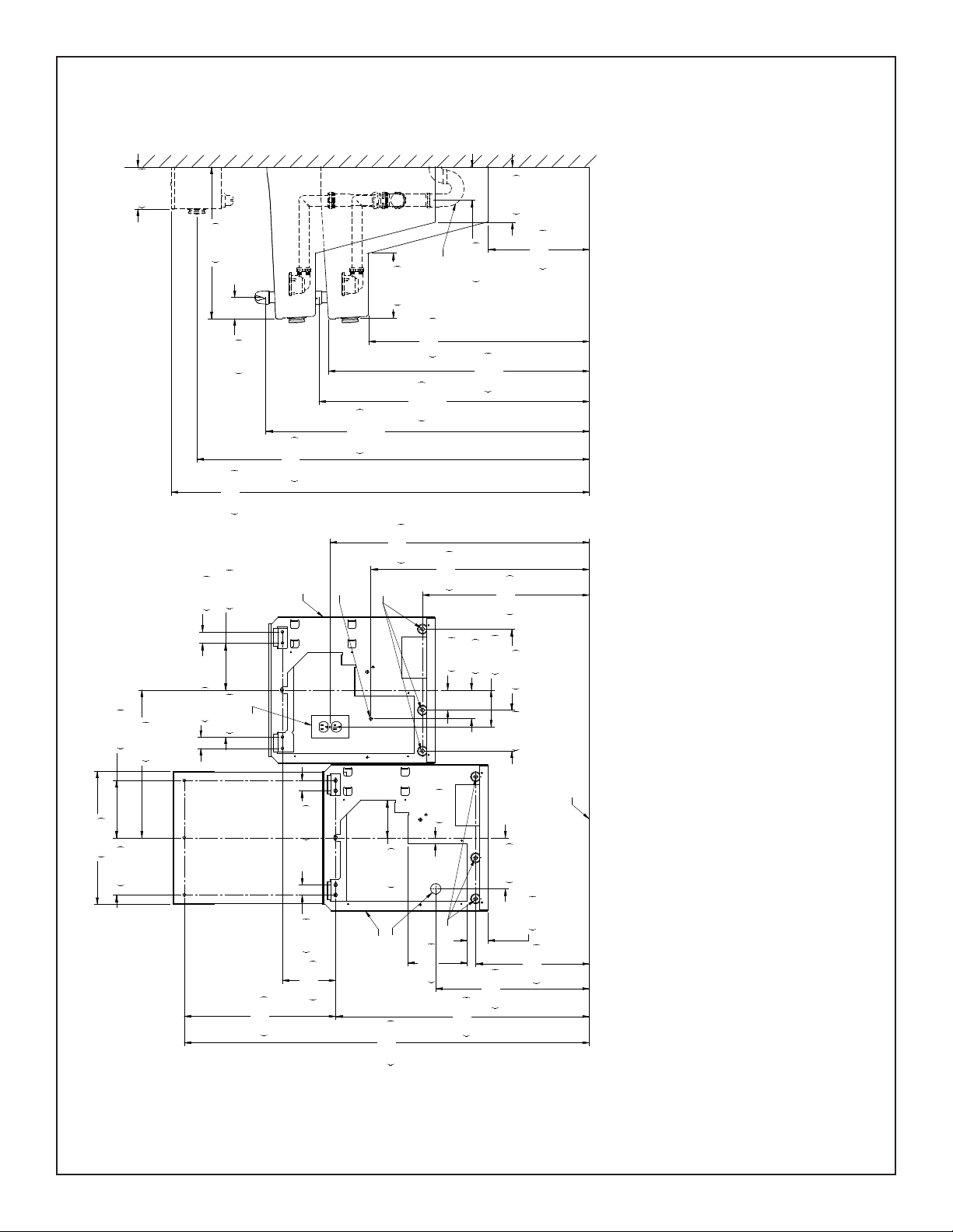
FIG. 3
VRCTLR8
* ADA REQUIREMENT
* REQUISITO DE A.D.A.
* EXIGENCE ADA
LEGEND/LEYENDA/LÉGENDE
A = RECOMMENDED WATER SUPPLY LOCATION 3/8 O.D. UNPLATED COPPER TUBE CONNECT STUB WITH SHUT OFF (BY OTHERS) 3 IN. (76mm) MAXIMUM OUT FROM WALL
La UBICACION 3/8 O RECOMENDADA de ABASTECIMIENTO DE AGUA. D. El TUBO del COBRE de UNPLATED CONECTA TALONARIO CON APAGO (POR OTROS) 3 en. (76 Mm) el MAXIMO FUERA DE
PARED
L’O.D de 3/8 d’EMPLACEMENT DE PROVISION D’EAU RECOMMANDE. LE TUBE DE CUIVRE DE UNPLATED CONNECTE STUB AVEC ETEINT (PAR LES AUTRES) 3 dans. (76 mm) le MAXIMUM HORS DU
MUR
B = RECOMMENDED LOCATION FOR WASTE OUTLET 1-1/2” O.D. DRAIN STUB 2 IN. OUT FROM WALL
UBICACIÓN RECOMENDADA PARA EL DRENAJE DE SALIDA DE AGUA, DE 1-1/2” DE DIÁMETRO. El TALONARIO 2 FUERA DE PARED
EMPLACEMENT RECOMMANDÉ POUR LE DRAIN DE D.E. 1-1/2” DE SORTIE D’EAU. STUB 2 HORS DU MUR
C = 1-1/2 TRAP NOT FURNISHED
PURGADOR DE 1-1/2 NO PROPORCIONADO
SIPHON 1-1/2 NON FOURNI
D = ELECTRICAL SUPPLY (3) WIRE RECESSED BOX
CAJA RECESIVA DE ALAMBRES (3) DE SUMINISTRO ELÉCTRICO
BOÎTE ENCASTRÉE D’ALIMENTATION ÉLECTRIQUE (3) FILS
E = INSURE PROPER VENTILATION BY MAINTAINING 6” (152 mm) (MIN.) CLEARANCE FROM CABINET LOUVERS TO WALL.
ASEGURE UNA VENTILACIÓN ADECUADA MANTENIENDO UN ESPACIO E 6” (152 mm) (MÍN.) DE HOLGURA ENTRE LA REJILLA DE VENTILACIÓN DEL MUEBLE Y LA PARED
ASSUREZ-VOUS UNE BONNE VENTILATION EN GARDANT 6” (152 mm) (MIN.) ENTRE LES ÉVENTS DE L’ENCEINTE ET LE MUR.
F = 7/16 BOLT HOLES FOR FASTENING UNIT TO WALL
AGUJEROS DE LAS TUERCAS DE 7/16 PARA SUJETAR LA UNIDAD A LA PARED
TROUS D’ÉCROUS 7/16 POUR FIXER L’APPAREIL AU MUR
**NEW INSTALLATIONS MUST USE GROUND FAULT CIRCUIT INTERRUPTER (GFCI)
**Las nuevas instalaciones deben utilizar el interruptor de circuito de tierra de la avería (GFCI)
**Les nouvelles installations doivent employer l’interrupteur de circuit moulu de défaut (GFCI)
(L)VRCTLDDWSC*A, *2A VRCTLRDDWSC*A, *2A , (L)VRCTL8WSC*1A, *2A, *3A, VRCTLR8WSC*1A, *2A, *3A
Page 6
98982C (Rev. T - 01/19)
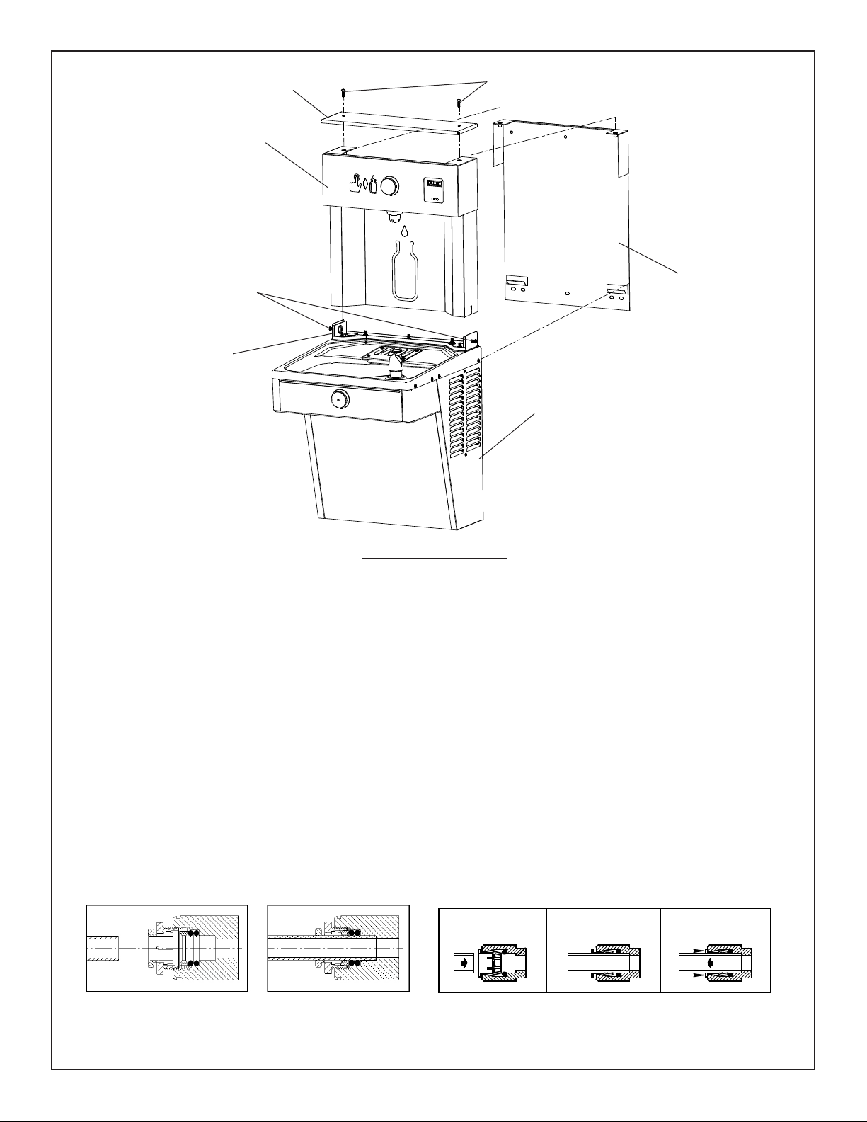
Fig. 5
Note: Screw the locknut hand tight to seal
Fig. 6
B CA
SIMPLY PUSH IN
TUBE TO ATTACH
TUBE IS SECURED
IN POSITION
PUSH IN COLLET
TO RELEASE TUBE
OPERATION OF QUICK CONNECT FITTINGS
PUSHING TUBE IN BEFORE
PULLING IT OUT HELPS TO
RELEASE TUBE
OPERATION OF QUICK CONNECT FITTINGS
SIMPLY PUSH IN
TUBE TO ATTACH
TUBE IS SECURED
IN POSITION
PUSH IN COLLET
TO RELEASE TUBE
PUSHING TUBE IN BEFORE
PULLING IT OUT HELPS TO
RELEASE TUBE
A B C
BOTTLE FILLER INSTALLATION
1) Remove wall mounting plates from Coolers. Install Wall Mounting Plates as per rough-in diagrams on Page 4 or 5 of this instruction.
NOTE: Mounting plates MUST be supported securely. Add xture support carrier if wall will not provide adequate support.
2) Install lower water cooler only at this time onto bracket as per rough-in diagram (See rough-in on Page 4 or 5). DO NOT connect power to cooler at this time or turn water
supply on.
3) Remove (L)VRCTL Bottle Filler from carton. Lay Bottle Filler on water cooler basin and cut insulation from tube even with bottom of unit, remove this insulation from the
3/8” tube, but do not discard. Feed the powercord and waterline through the hole on top of water cooler.
NOTE: To prevent scratching the basin place a towel or soft cloth over the entire basin when working above it.
4) With the power cord and waterline on top of water cooler, place Bottle Filler onto mounting bracket on basin. (See Fig. 4). Make sure bottle ller is installed properly on the
basin gasket.
5) Once Bottle Filler is installed on basin mounting bracket, tighten the two screws (supplied) one on each side of the bottle ller. Install Top Cover on Bottle Filler (See Fig.
4) with two mounting screws (supplied). Caution do not over tighten screws.
6) Secure non-refrigerated unit to wall, connect drains and water inlet.
7) Install the 1/4” poly tubing and insulation from the outlet of the lter to the union on top of the evaporator. Install the 1/4” poly tubing and insulation from the regulator in
the non-refrigerated cooler to one of the tees at the evaporator outlet. Install remaining tube insulation to the water line from bottle ller, connect Bottle Filler waterline inside
of the water cooler by connecting the 3/8” water line to the tee.
8) For Model LVRCTL Install lter cartridge, remove lter from carton, remove protective cap, attach lter to lter head by rmly inserting into head and rotating lter
clockwise.
NOTE: If existing plumbing rough-in locations (Drain, Water In, Electric Supply) do not allow the lter to be mounted inside the cooler cabinet the lter can be installed
horizontally below the unit. A retrot kit is available to mount the lter beneath the cooler.
9) Turn water supply on and inspect for leaks. Fix all leaks before continuing.
10) Once unit has been inspected for leaks and any leaks that are found are corrected, plug Bottle Filler and (L)VRCTL unit into wall. Be sure to reinstall fuse to the circuit or
switch the circuit breaker back to the “ON” position.
11) Once power is applied to Bottle Filler, the GREEN LED light should illuminate showing good lter status along with the LCD Bottle Counter.
12) Verify proper dispensing by depressing the button at the top of the Bottle Filler and verify water dispenses. Note: the rst initial dispenses might have air in line which
may cause a sputter. This will be eliminated once all air is purged from the line.
13) Once unit tests out, install Lower Panel back on (L)VRCTL water coolers. Unit is now ready for use.
MOUNTING BRACKET
FOR FASTENING UNIT
TO WALL
TOP COVER
MOUNTING
SCREWS
Fig. 4
MOUNTING SCREWS
DO NOT REMOVE
BOTTLE FILLER
WATER COOLER
NOTE: TRIM PLATES MUST BE
INSTALLED ON THE INSIDE
OF THE BOTTLE FILLER
SIDE PANEL SLOTS.
(L)VRCTLDDWSC*A, *2A VRCTLRDDWSC*A, *2A , (L)VRCTL8WSC*1A, *2A, *3A, VRCTLR8WSC*1A, *2A, *3A
Page 7
98982C (Rev. T - 01/19)
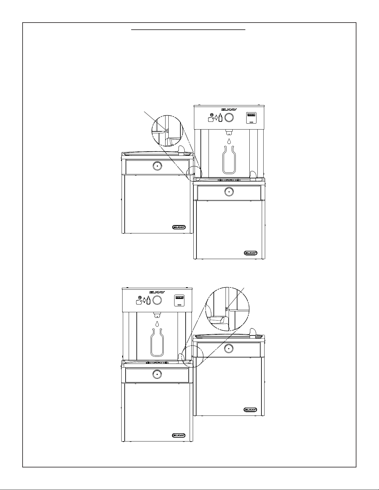
REMOVAL OF BOTTLE FILLER FOR SERVICING
1) Turn o the water supply to the Water Coolers. Unplug and/or turn o Circuit Breaker to Cooler(s) and Bottle Filler. NOTE: the Lower Front Panel of the coolers
may need to be removed. To prevent scratching the basin place a towel or soft cloth over the entire basin when working above it.
2) Loosen but DO NOT remove the Pinned Torx Head Screw from the outer side of the Bottle Filler and loosen but DO NOT remove the 1/4” hex. head bolt from
between the two cooler (See Figs 7 or 8). Remove the two (2) Pinned Torx Head Screws from the Top Cover & remove the Top Cover. The Bottle Filler may then be
lifted up and o the Water Cooler (The water line will still be connected from the Water Cooler to the Bottle Filler.)
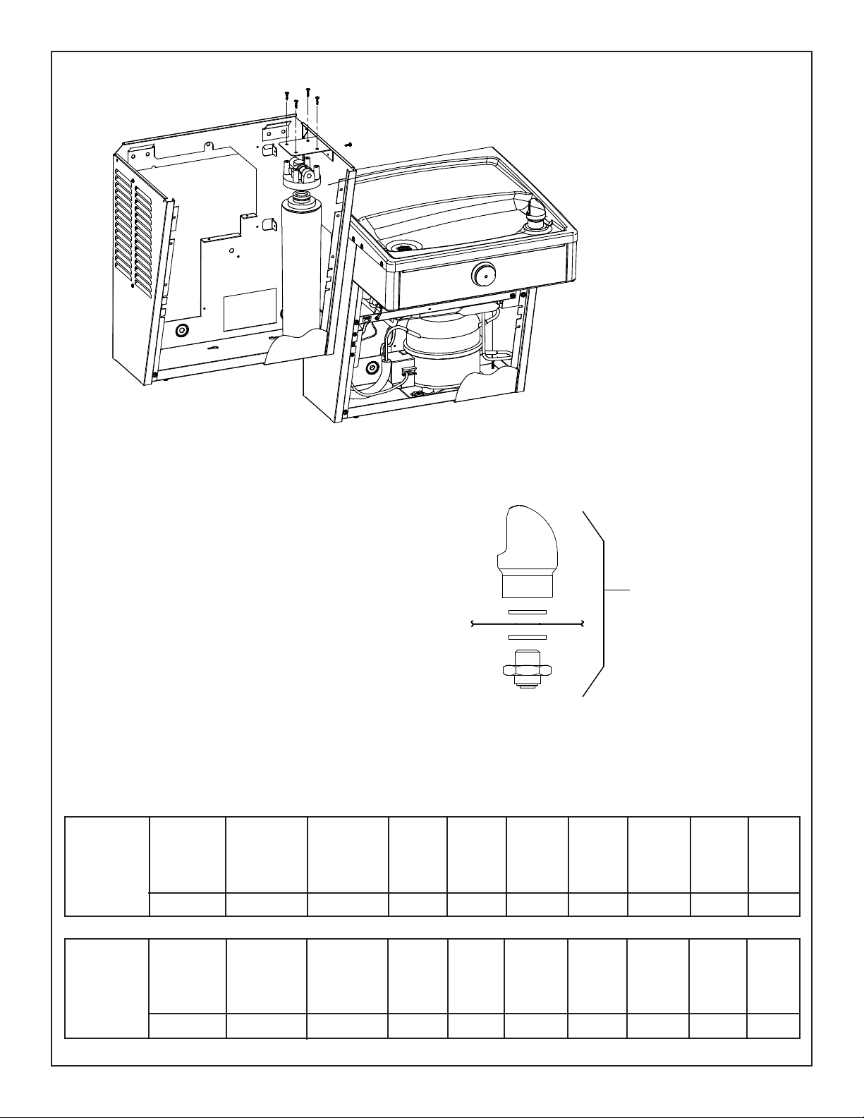
STANDARD TWO-LEVEL CONFIGURATION
STANDARD TWO-LEVEL REVERSED CONFIGURATION
Fig. 7
Fig. 8
1/4” HEX. HEAD BOLT THIS LOCATION ONLY
1/4” HEX. HEAD BOLT THIS LOCATION ONLY

(L)VRCTLDDWSC*A, *2A VRCTLRDDWSC*A, *2A , (L)VRCTL8WSC*1A, *2A, *3A, VRCTLR8WSC*1A, *2A, *3A
Page 8
98982C (Rev. T - 01/19)
IMPORTANT
ALL SERVICE TO BE PERFORMED BY AN
AUTHORIZED SERVICE PERSON
IMPORTANTE
TODO EL SERVICIO DEBERÁ SER EFECTUADO POR UNA
PERSONA DE SERVICIO AUTORIZADA
INSTALLATION DU SIPHON ET DU
SUPPORT DE SUSPENSION
1) Retirez le support de suspension à l’arrière du refroidis-
seur en enlevant une (1) vis.
2) Installez le support et le siphon tel qu’indiqué à la g. 2
ou 3.
NOTE : Le support de suspension DOIT être bien retenu en
place. Ajoutez des ferrures de xation si le mur n’ore
pas le soutien voulu.
IMPORTANT :
• Pour avoir une bonne position, on doit garder une
dimension de 4 1/8 po. (121mm) du mur à l’axe central
du siphon.
• Ancrez solidement le support au mur à l’aide des ve
(5) trous de xation d’un diam. 1/4 po.
3) Installez la soupape droite dans le tuyau de D.E. 3/8”.
HANGER BRACKETS & TRAP
INSTALLATION
1) Remove hanger bracket fastened to back of
cooler by removing one (1) screw.
2) Mount the hanger bracket and trap as shown
in Figure 2 or 3.
NOTE: Hanger Bracket MUST be supported
securely. Add xture support carrier if wall will
not provide adequate support.
IMPORTANT:
• 4 1/8 in. (121mm) dimension from wall to cen-
terline of trap must be maintained for proper t.
• Anchor hanger securely to wall using all ve (5)
1/4 in. dia. mounting holes.
3) Install straight valve for 3/8” O.D. tube.
INSTALACIÓN DE FIJADOR DE
SUSPENSIÓN Y DEL PURGADOR
1) Quite el jador de suspensión sujetados a la parte posterior del
enfriador quitando un (1) tornillo.
2) Monte el jador de suspensión y quite el purgador como se
muestra en la Fig. 2 o 3.
NOTA: El jador de suspensión DEBE de ser sostenido con seguri-
dad. Coloque portadores de soporte de instalaciones jas si la
pared no proveerá un soporte adecuado.
IMPORTANTE:
• Se debe mantener una dimensión de 4 1/8 pulgadas (121mm)
desde la pared hasta la línea central del purgador para que
calce de forma adecuada.
• Ancle el suspensor de forma segura a la pared usando todos
los cinco (5) agujeros de montaje de 1/4” de diámetro.
3) Instale la válvula directa para el tubo de 3/8” de diámetro externo.
INSTALLATION OF COOLER
4) Hang the cooler on the hanger bracket. Be
certain the hanger bracket is engaged properly
in the slots on the cooler back as shown in Figure
2 or 3.
5) Loosen the two (2) screws holding the lower
front panel at the bottom of cooler base and
two (2) screws at the top (Use torx bits sold
separately). Remove the front panel and set
aside.
6) Connect water inlet line--See Note 4 of General
Instructions.
7) Remove the slip nut and gasket from the trap
and install them on the cooler waste line mak-
ing sure that the end of the waste line ts into
the trap. Assemble the slip nut and gasket to
the trap and tighten securely.
INSTALACIÓN DEL ENFRIADOR DE AGUA
4) Suspenda el enfriador en el jador de suspensión. Asegúrese
que el jador de suspensión calce correctamente en las ranuras
de la parte posterior del enfriador como se indica en la gura 2
o 3.
5) Aoje los dos (2) tornillos que sostienen la parte inferior del panel
en la parte inferior de la base del enfriador y los dos (2) tornillos
en la parte superior (Utilice los pedacitos torx vendidos por
separado). Quite el panel frontal y póngalo a un lado.
6) Conectar el tubo de entrada de agua. Ver la Nota 4 en las
Instrucciones Generales.
7) Saque la tuerca deslizante y empaquetadura del colector e ins-
tálelos en la manquera de residous de la nevera, asequrándose
que el extremo de la manquera encaje en el colector. Coloque
la tuerca deslizante y la empaquetadura en el colector y apriete
rmermente.
INSTALLATION DU REFROIDISSEUR
4) Installez le refroidisseur sur le support en vous assurant
que ceux-ci sont bien installés dans les fentes à l’arrière
du refroidisseur tel qu’indiqué à la gure 2 ou 3.
5) Dégagez les deux (2) vis retenant le panneau inférieur
avant au bas de la base du refroidisseur ainsi que deux
(2) vis sur le dessus (Employez le peu Torx vendu
séparément). Retirez le panneau avant et mettez-le
de côté.
6) Connectez l’alimentation en eau. - Voir note 4 des
instructions générales.
7) Retirez l’écrou coulissant et le joint du siphon et les
installer sur la conduite de vidange de la fontaine en
s’assurant que l’extrémité de la conduite de vidange
s’ajuste dans le siphon. Assembler l’écrou coulissant
et le joint sur le siphon et srrer fermement.
PUESTA EN MARCHA
Ver también las Instrucciones Generales
8) La altura del chorro se ajusta en la fábrica a 45-50 PSI. Si la
presión de suministro varía mucho de esta valor, ajustar el tornillo
usar el agujero de acceso en el botón. El ajuste en sentido
horario elvará el chorro y en sentido contrahorario lo bajará
(inserte el destornillador). Para un ajuste mejor, el chorro debe
chocar con el depósito aproximadamente a
6-1/2”(165mm) del borboteador.
START UP
Also See General Instructions
8) Stream height is factory set at 45-50 PSI. If
supply pressure varies greatly from this, adjust
screw using the access hole in the pushbutton
(insert screwdriver). CW adjustment will raise
stream and CCW adjustment will lower stream.
For best adjustment, stream should hit basin
approximately 6-1/2” (165mm) from bubbler.
MISE EN MARCHE
Voir aussi les Instructions Générales
8) La pression du jet est réglée en usine 3,1 et 3,4 bars.
Si la pression d’alimentation varie fortement de cette
valeur employer l’ouverture d’accès dans le bouton-
poussoir. Un réglage dans le sens des aiguilles d’une
montre relève le jet, et un réglage dans le sens con-
traire l’abaisse (insérez le tournevis). Pour un réglage
optimum, le jet doit frapper le bassin à environ 165
mm du barboteur.
IMPORTANT
TOUT ENTRETIEN DOIT ÊTRE EFFECTUÉ PAR UN
REPRÉSENTANT AUTORISÉ
(L)VRCTLDDWSC*A, *2A VRCTLRDDWSC*A, *2A , (L)VRCTL8WSC*1A, *2A, *3A, VRCTLR8WSC*1A, *2A, *3A
Page 9
98982C (Rev. T - 01/19)
FIG. 9
(Refrigerated side shown)
15
1
13 (8)
9
1
25a
1
39 (TL)
40 (TLR)
15
18
24
35
13
13
32
33
7
7
7
7
5, 7
26
30
31
28
7
13
13
7
(Items 18 & 24 also
used on the LH unit)
1
13
13
30
9
9
15
15
22
(L)VRCTLDDWSC*A, *2A VRCTLRDDWSC*A, *2A , (L)VRCTL8WSC*1A, *2A, *3A, VRCTLR8WSC*1A, *2A, *3A
Page 10
98982C (Rev. T - 01/19)
Drain Pad Kit
98999C
25b
9
13
1
22
15
FIG. 10
(Bottle Filler side shown)
(L)VRCTLDDWSC*A, *2A VRCTLRDDWSC*A, *2A , (L)VRCTL8WSC*1A, *2A, *3A, VRCTLR8WSC*1A, *2A, *3A
Page 11
98982C (Rev. T - 01/19)
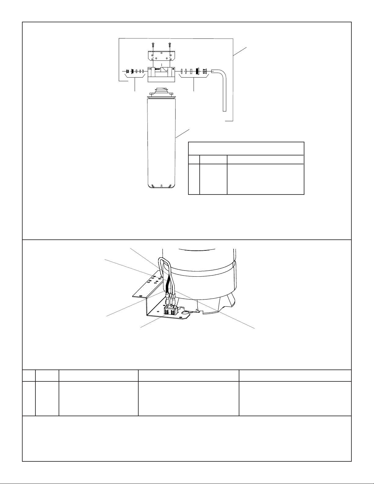
FIG. 11
Filter Installation Detail
Detalle de instalación del ltro
Détail de l’installation du ltre
Stainless Steel
Acero inoxidable
PANEL COLOR
COLOR TABLE
COLOR DEL
PANEL
TABLA DE LOS
COLORES
TABLE DE COU-
LEURS
COULEUR DU
PANNEAU
Item No. 39
Part No.
Artículos No.
No. de Pieza
Article Pièce
Item No. 31
Part No.
Artículos No.
No. de Pieza
Article Pièce
Item No. 32
Part No.
Artículos No.
No. de Pieza
Article Pièce
Item No. 33
Part No.
Artículos No.
No. de Pieza
Article Pièce
Item No. 34
Part No.
Artículos No.
No. de Pieza
Article Pièce
Item No. 35
Part No.
Artículos No.
No. de Pieza
Article Pièce
28525C28519C
28516C
28536C28522C 22955C
Unidad
de refrigeración
Refrig. Unit
Réfrigérateur
Stainless Steel
Acero inoxidable
PANEL COLOR
COLOR TABLE
COLOR DEL
PANEL
TABLA DE LOS
COLORES
TABLE DE COU-
LEURS
COULEUR DU
PANNEAU
Item No. 37
Part No.
Artículos No.
No. de Pieza
Article Pièce
Item No. 31
Part No.
Artículos No.
No. de Pieza
Article Pièce
Item No. 32
Part No.
Artículos No.
No. de Pieza
Article Pièce
Item No. 33
Part No.
Artículos No.
No. de Pieza
Article Pièce
Item No. 34
Part No.
Artículos No.
No. de Pieza
Article Pièce
Item No. 36
Part No.
Artículos No.
No. de Pieza
Article Pièce
28539C28519C
28516C
28528C28522C 22955C
Unidad
Izquierda
Left Unit
élément de
gauche
Item No. 40
Part No.
Artículos No.
No. de Pieza
Article Pièce
28562C
Item No. 38
Part No.
Artículos No.
No. de Pieza
Article Pièce
28559CAcero inoxydable
Acero inoxydable
FIG.12
VANDAL RESISTANT BUBBLER DETAIL
DETALLE DEL GRIFO RESISTENTE AL VANDALISMO
DESCRIPTION DU BARBOTEUR RESISTANT AU VANDALISME
Basin
Estanque
Bassin
1
(L)VRCTLDDWSC*A, *2A VRCTLRDDWSC*A, *2A , (L)VRCTL8WSC*1A, *2A, *3A, VRCTLR8WSC*1A, *2A, *3A
Page 12
98982C (Rev. T - 01/19)
FIG. 14
220V/240V Power Inlet Detail
220V/240V potencia entrada detalle
220V/240V alimentation détail
41
42
TO “N” TERMINAL
ON POWER INLET
(RIBBED SIDE)
TO GROUND TERMINAL
ON POWER INLET
(GREEN WIRE)
TO “L” TERMINAL
ON POWER INLET
(SMOOTH SIDE)
PARTS LIST 220/240V - LISTA DE PIEZAS 220/240V - LISTE DES PIÈCES 220/240V
0000000245
1000002147
1000002146
98751C
98752C
35826C
35827C
Kit - ventilador Motor/Cuchilla/cubierta/tuerca/tornillos
Paquete de Servicio del Compressor (50 Hz)
Paquete de Servicio del Compressor (60 Hz)
Kit - Relay/sobrecarga/cubierta (50Hz)
Kit - Relay/sobrecarga/cubierta (60Hz)
Entrada De Eléctrico
Montaje del alambre
Kit - Fan Motor/Blade/Shroud/Nut/Screws
Compressor Service Pak (50Hz)
Compressor Service Pak (60Hz)
Kit - Relay/Overload/Cover (50Hz)
Kit - Relay/Overload/Cover (60Hz)
Power Inlet
Wire Assembly
PART
NO.
DESCRIPTION DESCRIPCIÓN DESCRIPTION
Kit - ventilateur moteur/lame/carénage/écrou/vis
Trousse d’entr. supresseur (50Hz)
Trousse d’entr. supresseur (60Hz)
Kit - Relais/surcharge/Cover (50 Hz)
Kit - Relais/surcharge/Cover (60 Hz)
Entrée d’alimentation
Fil assemblée
ITEM
NO.
*REPLACE WITH SAME COMPRESSOR USED
IN ORIGINAL ASSEMBLY.
NOTE: All correspondence pertaining to any of the above
water coolers or orders for repair parts MUST include Model
No. and Serial No. of cooler, name and part number of replace-
ment part.
*REEMPLACE CON EL MISMO COMPRESOR
USADO EN EL ENSAMBLADO INICIAL.
NOTA: Toda la correspondencia relacionada con el
enfriador de agua anterior o con una orden de reparación
piezas DEBERÁ incluir el número de modelo y número
de serie del enfriador, el nombre y número de pieza de
la pieza de repuesto.
*REMPLACEZ AVEC LE MÊME SURPRESSEUR QUE
CELUI UTILISÉ ORIGINALEMENT.
NOTE : Toute correspondance au sujet des refroidis-
seurs d’eau courante ou toute commande de pièce
de rechange DOIT inclure le numéro de modèle et le
numéro de série du refroidisseur ainsi que le nom et le
numéro de pièce à remplacer.
3
*11
12
41
42
FIG. 13
Water Filter Exploded View
Filtro de agua despiece
Vue éclatée de l’eau ltre
DESCRIPTION
1
2
3
ITEM
NO.
PART NO.
51300C
51300C_12PK
98926C
1000003563
Filter Assy-3000 Gallon (Single)
Filter Assy-3000 Gallon (12 Pack)
Kit-Filter Head Fittings-includes John Guest
Fittings
Assy-Filter Head & Brkt includes Filter Head/
Mtg Brkt/John Guest Ftgs/Screws
WATERSENTRY
®
PLUS FILTER PARTS LIST
1
3
2
2
(L)VRCTLDDWSC*A, *2A VRCTLRDDWSC*A, *2A , (L)VRCTL8WSC*1A, *2A, *3A, VRCTLR8WSC*1A, *2A, *3A
Page 13
98982C (Rev. T - 01/19)
115V Wiring Diagram
Esquema eléctrico 115V
Diagramme de câblage 115V
220V Wiring Diagram
Esquema eléctrico 220V
Diagramme de câblage 220V
WHT
GND
BLK
FAN
3
1
2
5
M
S
C
1
2
3
COLD
CONTROL
(WATER)
6
RELAY
OVERLOAD
COMPRESSOR
RELAY
1
C
S
FAN
1
5
2
6
3
M
3
2
GND
SMOOTH
RIBBED
COLD
CONTROL
TO "L" TERMINAL
ON POWER INLET
TO "GROUND" TERMINAL
ON POWER INLET
TO "N" TERMINAL
ON POWER INLET
RELAY
OVERLOAD
COMPRESSOR
WIRING DIAGRAM 120 VOLT & 220 VOLT SINGLE & BI-LEVEL MICRO SWITCH ACTIVATION
DIAGRAMA DE CABLEADO DE 120 VOLTIOS Y 220 VOLTIOS SOLO Y BIPAP MICRO INTERRUPTOR ACTIVACIÓN
SCHÉMA DE CÂBLAGE 120 VOLTS & 220 VOLT SINGLE & VNDP MICRO INTERRUPTEUR D’ACTIVATION
FIG. 15
FIG. 16 FIG. 17
COM
N.O
.
N.C
.
MAIN BOARD
I.R.
BOARD
NOT
USED
LED
BOARD
GND
SOLENOID
RED
POWERCORD
FOUR PIN
CONNECTOR
FIVE PIN
CONNECTOR
WHITE
CONNECTOR FROM
POWER CORD
LINE VOLTAGE
SMOOTH
BLACK
GROUND
GREEN
NEUTRAL
WHITE
RIBBED
PIGGY BACK TERMINAL
ON POWER CORD
YELLOW
NOT USED
CAPPED
YELLOW
VIOLET
NOT USED
CAPPED
VIOLET
REMOTE RESET BUTTON
TWO PIN CONNECTOR FOR
REMOTE RESET BUTTON
RESET BUTTON
TWO PIN JUMPER
FOR MICRO SWITCH
ACTIVATION
MICRO SWITCH
NORMALLY OPEN
TWO PIN CONNECTOR
FOR MICRO SWITCH
REMOTE RESET BUTTON
(L)VRCTLDDWSC*A, *2A VRCTLRDDWSC*A, *2A , (L)VRCTL8WSC*1A, *2A, *3A, VRCTLR8WSC*1A, *2A, *3A
Page 14
98982C (Rev. T - 01/19)
VERIFY CONTROL BOARD SOFTWARE
1) To verify the software program of the control board the
unit will need to be shut down and restarted. The chiller
(if present) does not need to be shut down and restarted.
2) The units lower panel must be open to access the power
cord and wall outlet.
3) Shut down the unit by unplugging the power cord from the
wall outlet.
4) Restart the unit by plugging the power cord back into the
wall outlet.
5) Upon start up the bottle count display will show the
software designation of BF9.
ACCESSING THE PROGRAMMING BUTTON
1) To access the program button remove the bottom cover of
the water cooler. The reset button is located on the left side
of the cooler near the cold control. Replace the bottom
cover after programming operations are completed.
NOTE: There is a reset button located under the top cover
on the left hand side of the bottle ller also.
RESET THE FILTER MONITOR
1) Instructions apply to ltered units only.
2) Depress the program button for approximately 2 seconds
until the display changes then release. The display will
change and scroll through two messages:
“RST FLTR” – Reset Filter Monitor
“SETTINGS” – System Settings Sub Menu
If the program button is not pushed again the display
will scroll through the two messages above for
three cycles and then default back to bottle count and
be back in run mode.
3) When the display changes to “RST FLTR”, depress
the button again. The display will change to show
“FLT =”. Depress the button again and the display
will show “FLTR =0”
4) The Green LED should be illuminated indicating that
the visual lter monitor has been reset.
SETTING UNIT TYPE
1) Depress the program button for approximately 2 seconds
until the display changes then release. The display will
change and scroll through two messages:
“RST FLTR” – Reset Filter Status LED
“SETTINGS” – System Settings Sub Menu
If the program button is not pushed again the display
will scroll through the two messages above for
three cycles and then default back to bottle count
and be back in run mode.
2) When the display changes to “SETTINGS”, depress
the button again. The display will change to show
“RNG SET“- Range set for IR sensor.
“UNIT TYP“ - Type of unit (REFRIG or NON-REFRIG)
“RST BCNT“ - Reset bottle count
3) When display shows “UNIT TYPE” push program
button once the display will show current value
Can be REFRIG or NON-REFRIG
4) Push button once to change value. Once value is
selected the display will show the new value.
(Can be REFRIG or NON-REFRIG)
“REFRIG“ - stands for refrigerated product. In this
setting the ow rate is estimated at 1.0 gallon per minute.
“NON-REFRIG“ - stands for non-refrigerated product.
In this setting the ow rate is estimated
at 1.5 gallons per minute.
Both “REFRIG“ and “NON-REFRIG“ simulated
1 bottle equal to 20 oz.
5) Allow approximately 4 seconds to pass and the display
will return to bottle counter and be in run mode.
RESETTING BOTTLE COUNT
1) Depress the program button for approximately 2 seconds
until the display changes then release. The display will
change and scroll through two messages:
“RST FLTR” – Reset Filter Status LED
“SETTINGS” – System Settings Sub Menu
If the program button is not pushed again the display
will scroll through the two messages above for
three cycles and then default back to bottle count
and be back in run mode.
2) When the display changes to “SETTINGS”, depress
the button again. The display will change to show
“RNG SET“- Range set for IR sensor.
“UNIT TYP“ - Type of unit (REFRIG or NON-REFRIG)
“RST BCNT“ - Reset bottle count
If the button is not pushed again the display will scroll
through the three messages above for three cycles and
return to run mode.
3) When display shows “RST BCNT” push program button
once the display will show current value e.g. “00033183”.
4) Once display shows current value push the program
button once more to reset back to 0. The display will
show BTLCT = 0 for approximately 2 seconds and
then return to run mode showing 00000000 bottles.
5) To test bottle counter:
REFRIG units: Push and hold Bottle Filler Button for
9.4 seconds to see bottle counter count 00000001.
(This is based on lling a 20 oz. bottle).
NON-REFRIG units: Push and hold Bottle Filler Button for
6.25 seconds to see bottle counter count 00000001.
(This is based on lling a 20 oz. bottle)
BF9 PROGRAM
SETTING THE CONTROL BOARD
(L)VRCTLDDWSC*A, *2A VRCTLRDDWSC*A, *2A , (L)VRCTL8WSC*1A, *2A, *3A, VRCTLR8WSC*1A, *2A, *3A
Page 15
98982C (Rev. T - 01/19)
VERIFY CONTROL BOARD SOFTWARE
1) To verify the software program of the control board the unit will
need to be shut down and restarted. The chiller (if present) does
not need to be shut down and restarted.
2) The units lower panel must be open to access the power cord and
wall outlet.
3) Shut down the unit by unplugging the power cord from the wall
outlet or switching o the circuit breaker to the unit.
4) Restart the unit by plugging the power cord back into the wall
outlet or by switching on the circuit breaker to the unit.
5) Upon start up, the bottle count display will show the software
designation of BF11 or BF12.
ACCESSING THE PROGRAMMING BUTTON
1) To access the program button, remove the top cover of the bottle-
ller. Remove the two (2) screws holding top cover to bottle-ller
with a 5/32” allen wrench. Remove top cover. Do not discard
mounting screws, they will be needed to reinstall the top cover
after programming operations are completed. The programming
button is located at the top right side of the unit on the control
board.
RESET THE FILTER MONITOR
1) Instructions apply to ltered units only.
2) Depress the program button for approximately 2 seconds until
the display changes then release. The display will change and
scroll through two messages:
“RST FLTR” – Reset Filter Monitor
“SETTINGS” – System Settings Sub Menu
If the program button is not pushed again the display will scroll
through the two messages above for three cycles and then default
back to bottle count and be back in run mode.
3) When the display changes to “RST FLTR”, depress the button
again. The display will change to show “FLTR =”. Depress the
button again and the display will show “FLTR =0”
4) The Green LED should be illuminated indicating that the visual
lter monitor has been reset.
SETTING RANGE OF THE IR SENSOR WHERE APPLICABLE
1) Depress the program button for approximately 2 seconds until
the display changes then release. The display will change and
scroll through two messages:
“RST FLTR” – Reset Filter Status LED
“SETTINGS” – System Settings Sub Menu
If the program button is not pushed again the display will scroll
through the two messages above for three cycles and then default
back to bottle count and be back in run mode.
2) When the display changes to “SETTINGS”, depress the button
again. The display will change to show
“RNG SET” - Range set for IR sensor.
“UNIT TYP” - Type of unit (REFRIG or NON-RFRG)
“FLT SIZE” - Select lter capacity
“RST BCNT” - Reset bottle count
3) When display shows “RNG SET” push program button once the
display will show current value (can be 1 – 10) e.g. “RNG = 3”.
4) Once display shows current value push the program button to
scroll through value of 1 – 10. Select the desired range setting,
"1" being closest to sensor and "10" being farthest away.
5) Once range is selected allow approximately 4 seconds to pass and
then the display will go back to bottle counter and be in run mode.
6) Test bottle ller by placing bottle or hand in front of sensor to
make sure water is dispensed.
SETTING UNIT TYPE
1) Depress the program button for approximately 2 seconds until the
display changes then release. The display will change and scroll
through two messages:
“RST FLTR” – Reset Filter Status LED
“SETTINGS” – System Settings Sub Menu
If the program button is not pushed again the display will scroll
through the two messages above for three cycles and then default
back to bottle count and be back in run mode.
Continued from below:
2) When the display changes to “SETTINGS”, depress the button again.
The display will change to show
“RNG SET” - Range set for IR sensor.
“UNIT TYP” - Type of unit (REFRIG or NON-RFRG)
“FLT SIZE” - Select lter capacity
“RST BCNT” - Reset bottle count
3) When display shows “UNIT TYPE” push program button once the
display will show current value. Can be REFRIG or NON-RFRG
4) Push button once to change value. Once value is selected the display
will show the new value. (Can be REFRIG or NON-RFRG)
“REFRIG“ - stands for refrigerated product. In this setting the ow rate is
estimated at 1.0 gallon per minute.
“NON-RFRG“ - stands for nonrefrigerated product. In this setting the
ow rate is estimated at 1.5 gallons per minute. Both “REFRIG“ and
“NON-RFRG“ simulate 1 bottle equal to 20 oz.
5) Allow approximately 4 seconds to pass and the display will return to
bottle counter and be in run mode.
RESETTING BOTTLE COUNT
1) Depress the program button for approximately 2 seconds until the
display changes then release. The display will change and scroll
through two messages:
“RST FLTR” – Reset Filter Status LED
“SETTINGS” – System Settings Sub Menu
If the program button is not pushed again the display will scroll through
the two messages above for three cycles and then default back to bottle
count and be back in run mode.
2) When the display changes to “SETTINGS”, depress the button again.
The display will change to show:
“RNG SET”- Range set for IR sensor.
“UNIT TYP” - Type of unit (REFRIG or NON-RFRG)
“FLT SIZE” - Select lter capacity
“RST BCNT” - Reset bottle count
If the button is not pushed again the display will scroll through the four
messages above for three cycles and return to run mode.
3) When display shows “RST BCNT” push program button once the
display will show current value, e.g. “0033183”.
4) Once display shows current value push the program button once more
to reset back to 0. The display will show BTLCT = 0 for approximately 2
seconds and then return to run mode showing 00000000 bottles.
NOTE: Once the bottle count is reset to zero there is no way to
return to the previous bottle count.
5) Testing the bottle counter:
REFRIG units: Place bottle or hand in front of sensor for approximately
9 seconds to see bottle counter count 00000001,
(This is based on lling a 20 oz. bottle).
NON-RFRG units: Place bottle or hand in front of sensor for
approximately 6 seconds to see bottle counter count 00000001,
(This is based on lling a 20 oz bottle).
SETTING FILTER CAPACITY
1) Depress the program button for approximately 2 seconds until the
display changes then release. The display will change and scroll through
two messages:
“RST FLTR” – Reset Filter Status LED
“SETTINGS” – System Settings Sub Menu
If the program button is not pushed again the display will scroll through
the two messages above for three cycles and then default back to bottle
count and be back in run mode.
2) When the display changes to “SETTINGS”, depress the button again.
The display will change to show:
“RNG SET“- Range set for IR sensor.
“UNIT TYP“ - Type of unit (REFRIG or NON-RFRG)
“FLT SIZE” - Select lter capacity
“RST BCNT“ - Reset bottle count
If the button is not pushed again the display will scroll through the four
messages above for three cycles and return to run mode.
3) When display shows “FLT SIZE” push program button once. The display
will show current value. Can be 3000GAL or 6000GAL.
4) Push program button again to display the desired “FLT SIZE”.
5) Allow approximately 4 seconds to pass and the display will return to
bottle counter and be in run mode.
BF11 - BF12 PROGRAM
SETTING THE CONTROL BOARD
(L)VRCTLDDWSC*A, *2A VRCTLRDDWSC*A, *2A , (L)VRCTL8WSC*1A, *2A, *3A, VRCTLR8WSC*1A, *2A, *3A
Page 16
98982C (Rev. T - 01/19)
REPAIR SERVICE INFORMATION TOLL FREE NUMBER 1.800.260.6640
NÚMERO GRATIS DE SERVICIO 1.800.260.6640
INFORMATIONS POUR LE SERVICE PAR NUMERO SANS FRAIS 1.800.260.6640
97446C
98777C
98775C
98776C
98530C
56092C
98693C
98773C
600985551640
35870C
36322C
0000000238
0000001190
1000001602
98684C
1000001994
98778C
28596C
66703C
98724C
70002C
45929C
75524C
28617C
0000000966
29014C
22897C
27124C
55931C
1000004447
70864C
See Color Table
See Color Table
See Color Table
See Color Table
See Color Table
See Color Table
See Color Table
See Color Table
See Color Table
See Color Table
55996C
28551C
Bubbler Assy-VR
Kit - Compr Hardware/Clips/Studs/Grommets
Kit - Fan Motor/Blade/Shroud/Nut/Screws
Kit - Condenser/Drier
Kit - Regulator/Holder/Nut
Tubing - Poly (Cut To length)
Kit - PushButton/Sleeve/Screws/Nuts/Wshrs
Kit - Cold Control/Screws
Kit - Drain Plug/Strainer/Adapter/Screw
Power Cord
Compressor Serv. Pak
Kit - Relay/OverLoad/Cover
Kit - #10 Pinned Torx Screws/T-25 Bit
Kit - Elbow 5/16” - 1/4” (3 Pack)
Kit - Drain Elbow/Gasket/Nut/Washer
Kit - Tee 1/4” (3 Pack)
Kit - Heat Exchanger/Drier
Panel - Screen
Drier
Evaporator Replacement Assembly
Screw - #10 x 1/2” Lg. HHSM
Tube - Drain
Clip (Front & Rear Panels)
Screen - VR
Kit - Basin - Stainless Steel
Basin - Stainless Steel (BF)
Panel - Bottom Dispenser
Cover - Cold Control
Cover - Dispenser Bottom
Kit - Drain Tube Assy.
Screw - #8 x .62 Torx/Slot
Panel - RH Dispenser Side
Panel - LH Dispenser Side
Panel - Dispenser Front
Panel - Front Lower (Not Shown)
Panel - RH Rear
Panel - LH Rear
Panel - RH Rear TL
Panel - RH Rear TLR
Panel - LH Rear TL
Panel - LH Rear TLR
Strainer (See “General Instructions”)
Hanger Bracket
Conjunto de Pelele - resistente al vandalismo
Kit - compresor Hardware/Clips/espárragos/ojales
Kit - ventilador Motor/Cuchilla/cubierta/tuerca/tornillos
Kit - secador de condensador
Kit - tuerca de soporte de regulado
Tuberla de polietileno (Corte a la longitud)
Kit - pulsador/manga/tornillos/tuercas/arandelas
Kit - tornillos de Control de frío
Kit - enchufe/ltro/adaptador/tornillo de drenaje
Cable Eléctrico
Paquete de Serv. del Compresor
Kit - Relay/sobrecarga/cubierta
Kit - Torx #10 cubrió tornillos/T-25 bit
Kit - codo 5/16 “- 1/4” (paquete de 3)
Kit - desagüe Codo/Empaque/Tuerca/Arandela
Kit - t 1/4” (paquete de 3)
Kit - secador de intercambiador de calor
Panel - Pantalla
Secador
Conjunto de repuesto evaporador
Tornillo - #10 x 1/2” Lg. HHSM
Tubo de drenaje-
Brida (Paneles frontales y posteriores)
Pantalla - VR
Kit - La palangana - Acero que no se Mancha
Cuenca - rellenadores de botellas de acero inoxidable (BF)
Panel - Dispensador Inferior
Cubierta de Control del Frio
Cubierta-Dispensador Inferior
Kit - Conjunto de tubo de desagüe
Tornillo - #8 x .62 Torx/Slot
Panel - Lado derecho
Panel - Lado izquierdo
Panel - Dispensador Frontal
Panel - Frente Inferior (No mostrada)
Panel - Retrovisor Derecho
Panel - Retrovisor Izquierdo
Panel - Retrovisor Derecho TL
Panel - Retrovisor Derecho TLR
Panel - Retrovisor Izquierdo TL
Panel - Retrovisor Izquierdo TLR
Filtro Bifurcado (Vea “Instrucciones Generales”)
El Paréntesis del gancho
Barboteur Assemblée-anti-vandale
Kit - compresseur matériel/Clips/goujons/oeillets
Kit - ventilateur moteur/lame/carénage/écrou/vis
Kit - condenseur/séchoir
Kit - régulateur/titulaire/noix
Tubes - Polyéthyléne (Couper à la longueur)
Kit - bouton poussoir/manchon/vis/Ecrous/rondelles
Kit - froids/vis de réglage
Kit - che/ltre/adaptateur/vis de purge
Cordon d’alimentation
Trousse d ‘entr. Supreeeur
Kit - Relais/surcharge/Cover
Kit - #10 épinglé Torx vis/T-25 bit
Kit - coude 5/16” - 1/4” (Pack de 3)
Kit - vidange coude/joint/Écrou/Rondelle
Kit - Tee 1/4” (Pack de 3)
Kit - échangeur thermique/séchoir
Panneau - Écran
Déshydrateur
Ensemble de rechange évaporateur
Vis - #10 x 1/2 Lg. HHSM
Tube - Drain
Pince (panneaux avant et arrière)
Écran - VR
Kit - Le bassin - l’Acier de Stainless
Bassin - remplisseur de bouteille en acier inoxyd (BF)
Panneau - distributeur inférieur
Couvercle de Commande d’eau froide
Couvercle - distributeur inférieur
Kit - Tube de vidange
Vis - #8 x .62 Torx/Slot
Panneau - côté droit
Panneau - côté gauche
Panneau - avant
Panneau - avant inférieur (Pas montré)
Panneau - arrière droit
Panneau - arrière gauche
Panneau - arrière droit TL
Panneau - arrière droit TLR
Panneau - arrière gauche TL
Panneau - arrière gauche TLR
Grille (Voir “Directives Générales”)
Crochet de cintre
PART NO.
DESCRIPTION
DESCRIPCIÓN
DESCRIPTION
1
2
3
4
5
6
7
8
9
10
*11
12
13
14
15
16
17
18
19
20
21
22
23
24
25a
25b
26
27
28
29
30
31
32
33
34
35
36
37
38
39
40
NS
NS
ITEM
NO.
115V PARTS LIST/ 115V LISTA DE PIEZAS/ 115V LISTE DES PIÈCES
PRINTED IN U.S.A.
IMPRESO EN LOS E.E.U.U.
IMPRIMÉ AUX É.-U.
FOR PARTS, CONTACT YOUR LOCAL DISTRIBUTOR OR CALL 1.800.834.4816
PARA PIEZAS, CONTACTE A SU DISTRIBUIDOR LOCAL O LLAME AL 1.800.834.4816
POUR OBTENIR DES PIÈCES, CONTACTEZ VOTRE DISTRIBUTEUR LOCAL OU COMPOSEZ LE 1.800.834.4816
ELKAY MANUFACTURING COMPANY • 2222 CAMDEN COURT • OAK BROOK, IL 60523 • 630.574.8484 • www.elkay.com
*REPLACE WITH SAME COMPRESSOR USED
IN ORIGINAL ASSEMBLY.
NOTE: All correspondence pertaining to any of the above
water coolers or orders for repair parts MUST include Model
No. and Serial No. of cooler, name and part number of replace-
ment part.
*REEMPLACE CON EL MISMO COMPRESOR
USADO EN EL ENSAMBLADO INICIAL.
NOTA: Toda la correspondencia relacionada con el
enfriador de agua anterior o con una orden de reparación
piezas DEBERÁ incluir el número de modelo y número
de serie del enfriador, el nombre y número de pieza de
la pieza de repuesto.
*REMPLACEZ AVEC LE MÊME SURPRESSEUR QUE
CELUI UTILISÉ ORIGINALEMENT.
NOTE : Toute correspondance au sujet des refroidis-
seurs d’eau courante ou toute commande de pièce
de rechange DOIT inclure le numéro de modèle et le
numéro de série du refroidisseur ainsi que le nom et le
numéro de pièce à remplacer.
DESCRIPTION
98543C
1000004770
98546C
98549C
98552C
98631C
1000004771
98668C
98999C
99000C
1000001907
99002C
99003C
99004C
Kit - Electrical Package
Kit - Solenoid Valve Replacement 115V
Kit - Aerator Replacement
Kit - Hardware & Waterway Parts
Kit - Retro Filter Mounting
Kit - Electrical Package 220V
Kit - Solenoid Valve Replacement 220V
Kit - Filter Mounting Cover
Kit - Drain Pad
Kit - Button Assembly
Kit - Top Cover Replacement
Kit - Gasket VR BF Tower/Basin
Kit - Reset Switch
Kit - Micro Switch
BOTTLE FILLER REPLACEMENT PART KITS BOTELLA RELLENO REEMPLAZO PARTE KITS BOUTEILLE DE REMPLISSAGE REMPLACEMENT PARTIE KITS
PART NO.
DESCRIPCIÓN DESCRIPTION
Kit - Package électrique
Kit - remplacement de la Valve solénoïde 115V
Kit - aérateur Remplacement
Kit - matériel & Waterway pièces
Kit - rétro montage du ltre
Kit - Package électrique 220V
Kit - remplacement de la Valve solénoïde 220V
Kit - couverture de montage du ltre
Kit - Drain Pad
Kit de montage de bouton
Kit - remplacement du capot supérieur
Kit - joint anti-vandalisme tour de remplissage de bouteille/bassin
Kit - interrupteur de réinitialisation
Kit - Micro interrupteur
Kit - paquete eléctrico
Kit - reemplazo de la válvula de solenoide 115V
Kit - reemplazo de aireador
Kit - Hardware y partes de la canal
Kit - Retro montaje del ltro
Kit - paquete eléctrico 220V
Kit de reemplazo de la válvula de solenoide 220V-
Kit de montaje tapa del ltro-
Kit de drenaje de Pad-
Kit - conjunto de botón
Kit - reemplazo de la cubierta superior
Kit - junta resistente al vandalismo botella relleno torre/cuenca
Kit - interruptor de reinicio
Kit - interruptor Micro
NS - NOT SHOWN