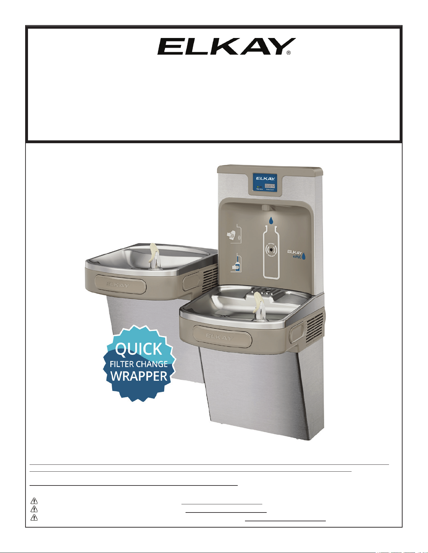
Enhanced
INSTALLATION & USE MANUAL
LZ
™
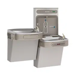
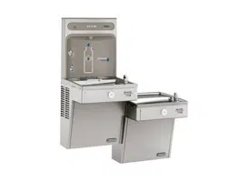
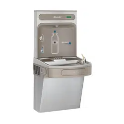
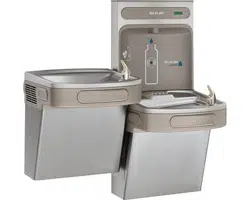
Series Bottle Filling Stations & Coolers
Patent zurn-elkay.com/patents
*Versatile cooler design allows units to be installed either left-hand high and right-hand low or left-low and right high.
Basin change may be required. See desired rough-in to help determine if the basin change is necessary.
Important: The refrigerated coolers must be hung on the right side.
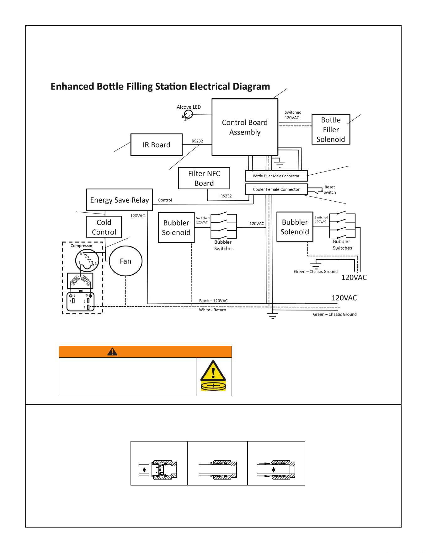
WARNING: Cancer and Reproductive Harm - www.P65Warnings.ca.gov
ADVERTENCIA: Cáncer y daño reproductivo - www.P65Warnings.ca.gov
AVERTISSEMENT: Cancer et effets néfastes sur la reproduction - www.P65Warnings.ca.gov
Page 1 2000001213 (Rev. C - 02/24)
ENLZSTL8WS_1G_PIVOT
C
L
C
L
FINISHED FLOOR
15"
381mm
2 7/8"
73mm
2"
51mm
28 13/16"
731mm
13 15/16"
354mm
2"
51mm
3 7/8"
98mm
5 3/4"
146mm
7"
178mm
7"
178mm
17 7/16"
443mm
19"
483mm
21 7/8"
556mm
34 5/16"
872mm
51 9/16"
1310mm
6 3/8"
162mm
6 3/8"
162mm
7"
178mm
7"
178mm
18"
458mm
12 1/2"
318mm
27"
686mm
ADA
REQUIREMENT
31 5/16"
796mm
RIM
HEIGHT
32 7/8"
835mm
ORIFICE
HEIGHT
19"
482mm
3 1/2"
90mm
19"
483mm
7/16" X 3/4" (11mm X 19mm)
OBROUND HOLES (6)
Ø
9/32" (7mm)
HOLES (12)
A
PREFERRED
LOCATION
B
D
ALTERNATE
LOCATION
8 1/16"
205mm
C
HANGER
BRACKET
36 13/16"
936mm
RIM
HEIGHT
38 3/8"
975mm
ORIFICE
HEIGHT
E
F
F
19 7/16"
494mm
2"
51mm
22 15/16"
583mm
24 1/2"
622mm
2"
51mm
7/8"
22mm
18 3/8"
467mm
6 3/8"
162mm
6 3/8"
162mm
A
ALTERNATE
LOCATION
E
FILTER
38 1/2"
979mm
ACTIVATION
SENSOR
1 7/8"
48mm
3"
76mm
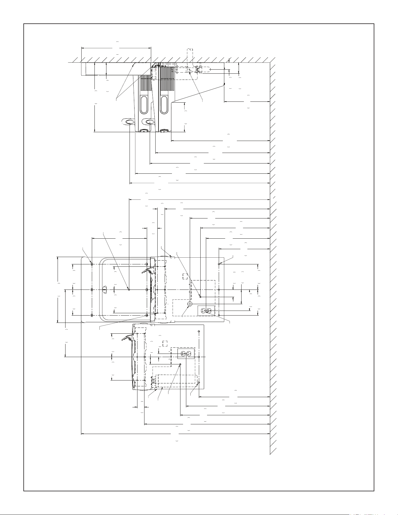
REDUCE HEIGHT BY 3 INCHES FOR INSTALLATION OF CHILDREN’S ADA COOLER
Reduzca la altura en 76 mm (3") para la instalación del bebedero con clasicación ADA para niños
Réduire la hauteur de 76 mm (3 PO) pour les installations à la norme ADA enfants
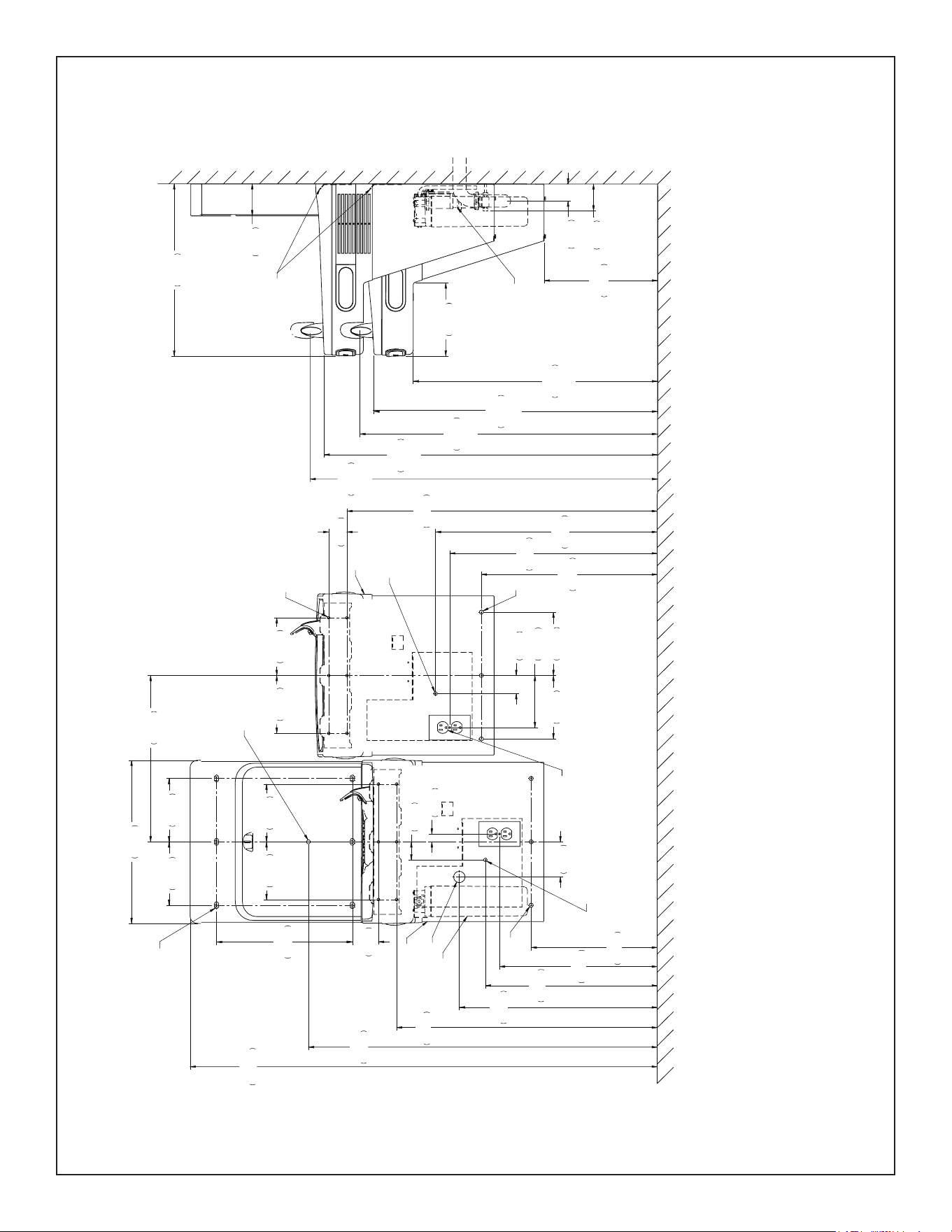
STANDARD ROUGH-IN FOR LEFT-HAND HIGH, BOTTLE FILLER LOW MODELS
BOSQUEJO ESTÁNDAR PARA MODELOS CON LA LLENADORA DE BOTELLAS BAJA Y LA PARTE IZQUIERDA ALTA
DISPOSITION DE CANALISATIONS STANDARD, POUR INSTALLATION GAUCHE HAUTE ET REMPLISSEUSE DE BOUTEILLE BASSE
FIG. 1
LEGEND/LEYENDA/LÉGENDE
A = RECOMMENDED WATER SUPPLY LOCATION 3/8 O.D. UNPLATED COPPER TUBE CONNECT STUB WITH SHUT OFF (BY OTHERS) 3 IN. (76mm)
MAXIMUM OUT FROM WALL
UBICACIÓN RECOMENDADA DEL SUMINISTRO DE AGUA. TUBERÍA DE COBRE SIN REVESTIMIENTO DE 3/8" DE DIÁM. EXT. ADAPTADOR DE
CONEXIÓN CON VÁLVULA DE CIERRE (DE TERCEROS) MÁXIMO A 76 mm (3") DE LA PARED.
EMPLACEMENT RECOMMANDÉ DE L’ARRIVÉE D’EAU. TUBE EN CUIVRE NON PLAQUÉ DE 3/8 PO DE DIA. EXT. RACCORDER À LA CONDUITE
D’ALIMENTATION AVEC UN ROBINET D’ARRÊT (NON FOURNI) À 76 mm (3 PO) MAXIMUM DU MUR
B = RECOMMENDED LOCATION FOR WASTE OUTLET 1-1/2" O.D. DRAIN STUB 2 IN. OUT FROM WALL
UBICACIÓN RECOMENDADA DE LA SALIDA DE DESECHOS. ADAPTADOR DE DESAGÜE DE 1-1/2" DE DIÁM. EXT., A 51 mm (2") DE LA PARED.
EMPLACEMENT RECOMMANDÉ DE LA SORTIE D’ÉCOULEMENT. CONDUITE D’ÉVACUATION DE 1-1/2 PO DE DIA. EXT. DÉPASSANT DE 51 mm
(2 PO) HORS DU MUR
C = 1-1/2" TRAP NOT FURNISHED
NO SE INCLUYE SIFÓN DE 1-1/2"
SIPHON DE 1-1/2 PO NON FOURNI
LEGEND/LEYENDA/LÉGENDE
D = ELECTRICAL SUPPLY (3) WIRE RECESSED BOX DUPLEX OUTLET**
SUMINISTRO ELÉCTRICO (3) CAJA ENCHUFE DE ALAMBRE SALIDA DÚPLEX
ALIMENTATION ÉLECTRIQUE (3) BOÎTIER ENCASTRÉ
E = INSURE PROPER VENTILATION BY MAINTAINING 6" (152 mm) (MIN.) CLEARANCE FROM CABINET LOUVERS TO WALL.
PARA GARANTIZAR LA VENTILACIÓN ADECUADA, MANTENGA 152 mm (6") (MÍN.) DE SEPARACIÓN DESDE LAS REJILLAS DEL GABINETE HASTA
LA PARED.
POUR ASSURER UNE AÉRATION SUFFISANTE, PRÉVOIR UN DÉGAGEMENT DE 152 mm (6 PO) (MIN.) ENTRE LES ÉVENTS DE L’ENCEINTE ET LE
MUR.
F = 7/16 BOLT HOLES FOR FASTENING UNIT TO WALL
ORIFICIOS PARA PERNOS DE 7/16, PARA FIJAR LA UNIDAD A LA PARED
TROUS DE VIS DE 7/16 PO POUR LA FIXATION DE L’APPAREIL AU MUR
**NEW INSTALLATIONS MUST USE GROUND FAULT CIRCUIT INTERRUPTER (GFCI)
**Las nuevas instalaciones deben usar un interruptor de circuito de falla a tierra (GFCI, por sus siglas en inglés)
**Les nouvelles installations doivent comporter un disjoncteur différentiel (GFCI)
NOTE: It is highly recommended that the circuit be dedicated and the load protection be sized for 20 amps.
NOTA: Es muy recomendable que el circuito esté dedicado y que la protección de carga tenga un tamaño de 20 amperios.
REMARQUE: Il est fortement recommandé de dédier le circuit et de dimensionner la protection de charge à 20 ampères.
Page 2
ENLZSTL8WS_1G_PIVOT
2000001213 (Rev. C - 02/24)
C
L
C
L
FINI SHED FLOOR
15"
381mm
2 7/8"
73mm
34 5/16"
871mm
19 7/16"
494mm
2"
51mm
5 3/4"
146mm
7"
178mm
7"
178mm
22 15/16"
583mm
24 1/2"
622mm
28 13/16"
732mm
6 3/8"
162mm
6 3/8"
162mm
7"
178mm
7"
178mm
18"
458mm
12 1/2"
318mm
27"
686mm
ADA
REQUIREMENT
31 5/16"
796mm
RIM
HEIGHT
32 7/8"
835mm
ORIFICE
HEIGHT
3 1/2"
90mm
A
PREFERRED
LOCATION
B
D
ALTERNATE
LOCATION
8 1/16"
205mm
C
HANGER
BRACKET
38 3/8"
975mm
ORIFICE
HEIGHT
E
F
F
13 15/16"
354mm
17 7/16"
443mm
19"
483mm
2"
51mm
7/8"
22mm
18 3/8"
467mm
6 3/8"
162mm
6 3/8"
162mm
A
ALTERNATE
LOCATION
E
FILTER
38 9/16"
979mm
ACTIVATION
SENSOR
1 7/8"
48mm
3"
76mm
2"
51mm
Ø 9/32" (7mm)
HOLES (12)
3 7/8"
98mm
21 7/8"
556mm
51 5/8"
1311mm
7/16" X 3/4" (11mm X 19mm)
OBROUND HOLES (6)
19"
483mm
36 13/16"
936mm
RIM
HEIGHT
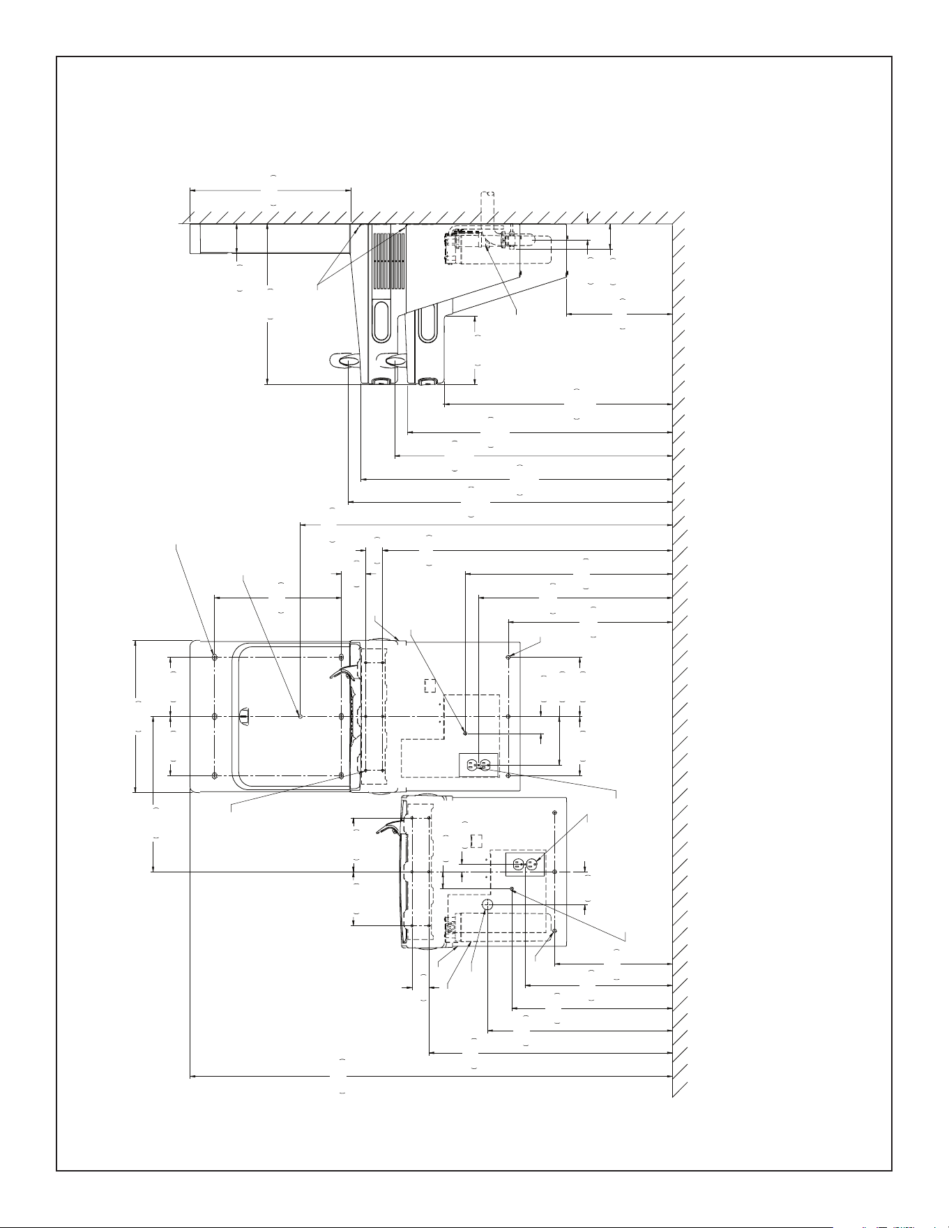
ALTERNATE ROUGH-IN FOR RIGHT-HAND HIGH, BOTTLE FILLER LOW MODELS – REQUIRES BASIN ASSY CHANGE
BOSQUEJO ALTERNATIVO PARA MODELOS CON LA LLENADORA DE BOTELLAS BAJA Y LA PARTE DERECHA ALTA: REQUIERE CAMBIAR EL CONJUNTO DE TARJA
AUTRE DISPOSITION DE CANALISATIONS, POUR INSTALLATION DROITE HAUTE ET REMPLISSEUSE DE BOUTEILLE BASSE – MODIFICATION DE LA FONTAINE REQUISE
FIG. 2
REDUCE HEIGHT BY 3 INCHES FOR INSTALLATION OF CHILDREN’S ADA COOLER
Reduzca la altura en 76 mm (3") para la instalación del bebedero con clasicación ADA para niños
Réduire la hauteur de 76 mm (3 po) pour les installations à la norme ADA enfants
LEGEND/LEYENDA/LÉGENDE
A = RECOMMENDED WATER SUPPLY LOCATION 3/8 O.D. UNPLATED COPPER TUBE CONNECT STUB WITH SHUT OFF (BY OTHERS) 3 IN. (76mm)
MAXIMUM OUT FROM WALL
UBICACIÓN RECOMENDADA DEL SUMINISTRO DE AGUA. TUBERÍA DE COBRE SIN REVESTIMIENTO DE 3/8" DE DIÁM. EXT. ADAPTADOR DE
CONEXIÓN CON VÁLVULA DE CIERRE (DE TERCEROS) MÁXIMO A 76 mm (3") DE LA PARED.
EMPLACEMENT RECOMMANDÉ DE L’ARRIVÉE D’EAU. TUBE EN CUIVRE NON PLAQUÉ DE 3/8 PO DE DIA. EXT. RACCORDER À LA CONDUITE
D’ALIMENTATION AVEC UN ROBINET D’ARRÊT (NON FOURNI) À 76 mm (3 PO) MAXIMUM DU MUR
B = RECOMMENDED LOCATION FOR WASTE OUTLET 1-1/2" O.D. DRAIN STUB 2 IN. OUT FROM WALL
UBICACIÓN RECOMENDADA DE LA SALIDA DE DESECHOS. ADAPTADOR DE DESAGÜE DE 1-1/2" DE DIÁM. EXT., A 51 mm (2") DE LA PARED.
EMPLACEMENT RECOMMANDÉ DE LA SORTIE D’ÉCOULEMENT. CONDUITE D’ÉVACUATION DE 1-1/2 PO DE DIA. EXT. DÉPASSANT DE 51 mm
(2 PO) HORS DU MUR
C = 1-1/2" TRAP NOT FURNISHED
NO SE INCLUYE SIFÓN DE 1-1/2"
SIPHON DE 1-1/2 PO NON FOURNI
LEGEND/LEYENDA/LÉGENDE
D = ELECTRICAL SUPPLY (3) WIRE RECESSED BOX DUPLEX OUTLET**
SUMINISTRO ELÉCTRICO (3) CAJA ENCHUFE DE ALAMBRE SALIDA DÚPLEX
ALIMENTATION ÉLECTRIQUE (3) BOÎTIER ENCASTRÉ
E = INSURE PROPER VENTILATION BY MAINTAINING 6" (152 mm) (MIN.) CLEARANCE FROM CABINET LOUVERS TO WALL.
PARA GARANTIZAR LA VENTILACIÓN ADECUADA, MANTENGA 152 mm (6") (MÍN.) DE SEPARACIÓN DESDE LAS REJILLAS DEL GABINETE HASTA
LA PARED.
POUR ASSURER UNE AÉRATION SUFFISANTE, PRÉVOIR UN DÉGAGEMENT DE 152 mm (6 PO) (MIN.) ENTRE LES ÉVENTS DE L’ENCEINTE ET LE
MUR.
F = 7/16 BOLT HOLES FOR FASTENING UNIT TO WALL
ORIFICIOS PARA PERNOS DE 7/16, PARA FIJAR LA UNIDAD A LA PARED
TROUS DE VIS DE 7/16 PO POUR LA FIXATION DE L’APPAREIL AU MUR
**NEW INSTALLATIONS MUST USE GROUND FAULT CIRCUIT INTERRUPTER (GFCI)
**Las nuevas instalaciones deben usar un interruptor de circuito de falla a tierra (GFCI, por sus siglas en inglés)
**Les nouvelles installations doivent comporter un disjoncteur différentiel (GFCI)
NOTE: It is highly recommended that the circuit be dedicated and the load protection be sized for 20 amps.
NOTA: Es muy recomendable que el circuito esté dedicado y que la protección de carga tenga un tamaño de 20 amperios.
REMARQUE: Il est fortement recommandé de dédier le circuit et de dimensionner la protection de charge à 20 ampères.
Page 3 2000001213 (Rev. C - 02/24)
ENLZSTL8WS_1G_PIVOT
C
L
C
L
FINISHED FLOOR
2"
51mm
34 5/16"
871mm
19 7/16"
494mm
2"
51mm
5 3/4"
146mm
7"
178mm
7"
178mm
22 15/16"
583mm
24 1/2"
622mm
28 13/16"
732mm
57 1/16"
1450mm
7"
178mm
7"
178mm
18"
458mm
12 1/2"
318mm
27"
686mm
ADA
REQUIREMENT
36 13/16"
936mm
RIM
HEIGHT
38 3/8"
975mm
ORIFICE
HEIGHT
19"
482mm
3 1/2"
90mm
19"
483mm
7/16" X 3/4" (11mm X 19mm)
OBROUND HOLES (6)
Ø 9/32" (7mm)
HOLES (12)
A
PREFERRED
LOCATION
B
D
ALTERNATE
LOCATION
8 1/16"
205mm
C
HANGER
BRACKET
31 5/16"
796mm
RIM
HEIGHT
32 7/8"
835mm
ORIFICE
HEIGHT
E
F
F
13 15/16"
354mm
2"
51mm
17 7/16"
443mm
19"
483mm
2"
51mm
7/8"
22mm
18 3/8"
467mm
6 3/8"
162mm
6 3/8"
162mm
A
ALTERNATE
LOCATION
E
FILTER
44"
1118mm
ACTIVATION
SENSOR
1 7/8"
48mm
3"
76mm
15"
381mm
2 7/8"
73mm
D
PREFERRED
LOCATION
3 7/8"
98mm
21 7/8"
556mm
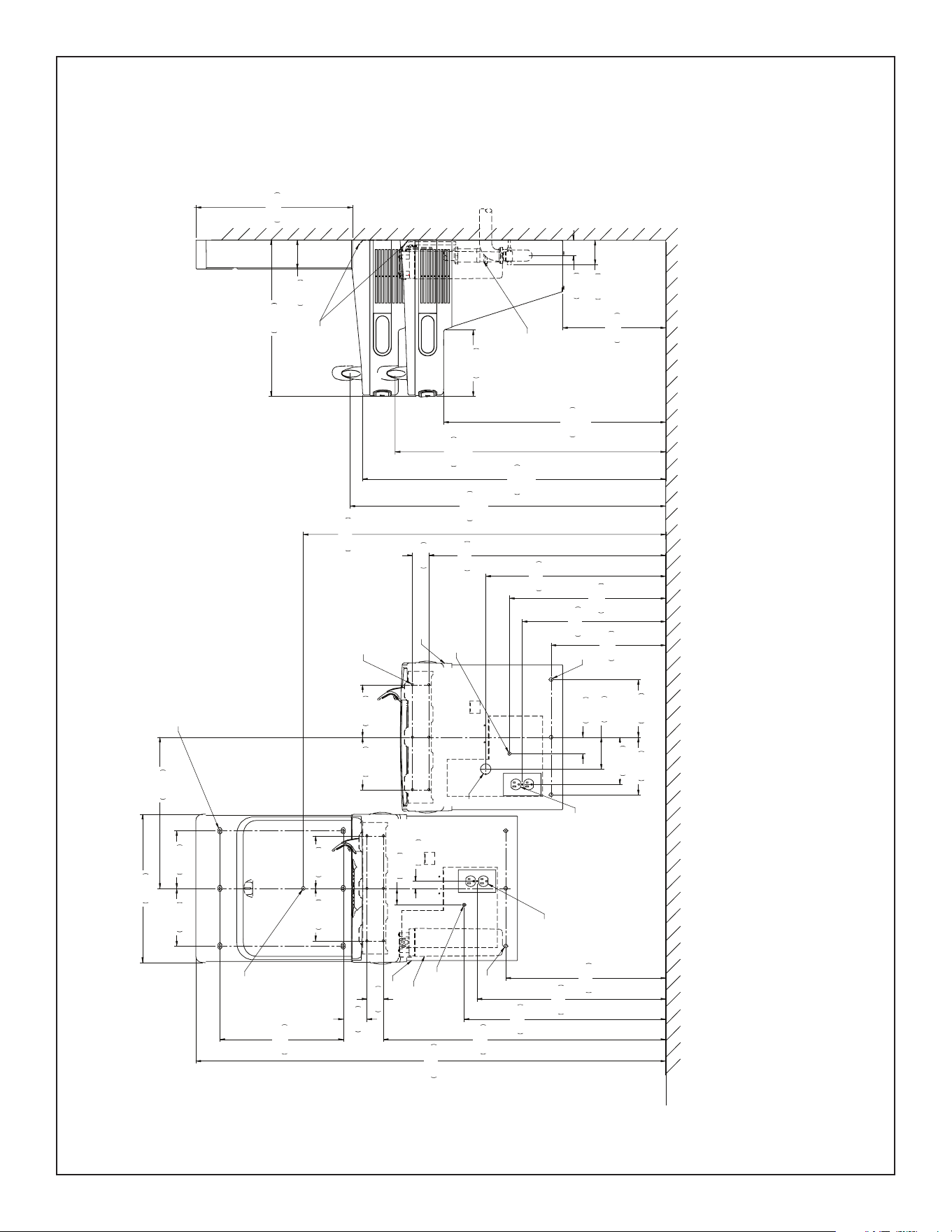
ALTERNATE ROUGH-IN FOR LEFT-HAND LOW, BOTTLE FILLER HIGH MODELS
BOSQUEJO ALTERNATIVO PARA MODELOS CON LA LLENADORA DE BOTELLAS ALTA Y LA PARTE IZQUIERDA BAJA
AUTRE DISPOSITION DE CANALISATIONS, POUR INSTALLATION GAUCHE BASSE ET REMPLISSEUSE DE BOUTEILLE HAUTE
FIG. 3
REDUCE HEIGHT BY 3 INCHES FOR INSTALLATION OF CHILDREN’S ADA COOLER
Reduzca la altura en 76 mm (3 in) para la instalación del bebedero con clasicación ADA para niños
Réduire la hauteur de 76 mm (3 po) pour les installations à la norme ADA enfants
LEGEND/LEYENDA/LÉGENDE
A = RECOMMENDED WATER SUPPLY LOCATION 3/8 O.D. UNPLATED COPPER TUBE CONNECT STUB WITH SHUT OFF (BY OTHERS) 3 IN. (76mm)
MAXIMUM OUT FROM WALL
UBICACIÓN RECOMENDADA DEL SUMINISTRO DE AGUA. TUBERÍA DE COBRE SIN REVESTIMIENTO DE 3/8" DE DIÁM. EXT. ADAPTADOR DE
CONEXIÓN CON VÁLVULA DE CIERRE (DE TERCEROS) MÁXIMO A 76 mm (3") DE LA PARED.
EMPLACEMENT RECOMMANDÉ DE L’ARRIVÉE D’EAU. TUBE EN CUIVRE NON PLAQUÉ DE 3/8 PO DE DIA. EXT. RACCORDER À LA CONDUITE
D’ALIMENTATION AVEC UN ROBINET D’ARRÊT (NON FOURNI) À 76 mm (3 PO) MAXIMUM DU MUR
B = RECOMMENDED LOCATION FOR WASTE OUTLET 1-1/2" O.D. DRAIN STUB 2 IN. OUT FROM WALL
UBICACIÓN RECOMENDADA DE LA SALIDA DE DESECHOS. ADAPTADOR DE DESAGÜE DE 1-1/2" DE DIÁM. EXT., A 51 mm (2") DE LA PARED.
EMPLACEMENT RECOMMANDÉ DE LA SORTIE D’ÉCOULEMENT. CONDUITE D’ÉVACUATION DE 1-1/2 PO DE DIA. EXT. DÉPASSANT DE 51 mm
(2 PO) HORS DU MUR
C = 1-1/2" TRAP NOT FURNISHED
NO SE INCLUYE SIFÓN DE 1-1/2"
SIPHON DE 1-1/2 PO NON FOURNI
LEGEND/LEYENDA/LÉGENDE
D = ELECTRICAL SUPPLY (3) WIRE RECESSED BOX DUPLEX OUTLET**
SUMINISTRO ELÉCTRICO (3) CAJA ENCHUFE DE ALAMBRE SALIDA DÚPLEX
ALIMENTATION ÉLECTRIQUE (3) BOÎTIER ENCASTRÉ
E = INSURE PROPER VENTILATION BY MAINTAINING 6" (152 mm) (MIN.) CLEARANCE FROM CABINET LOUVERS TO WALL.
PARA GARANTIZAR LA VENTILACIÓN ADECUADA, MANTENGA 152 mm (6") (MÍN.) DE SEPARACIÓN DESDE LAS REJILLAS DEL GABINETE
HASTA LA PARED.
POUR ASSURER UNE AÉRATION SUFFISANTE, PRÉVOIR UN DÉGAGEMENT DE 152 mm (6 PO) (MIN.) ENTRE LES ÉVENTS DE L’ENCEINTE
ET LE MUR.
F = 7/16 BOLT HOLES FOR FASTENING UNIT TO WALL
ORIFICIOS PARA PERNOS DE 7/16, PARA FIJAR LA UNIDAD A LA PARED
TROUS DE VIS DE 7/16 PO POUR LA FIXATION DE L’APPAREIL AU MUR
**NEW INSTALLATIONS MUST USE GROUND FAULT CIRCUIT INTERRUPTER (GFCI)
**Las nuevas instalaciones deben usar un interruptor de circuito de falla a tierra (GFCI)
**Les nouvelles installations doivent comporter un disjoncteur différentiel (GFCI)
Page 4
ENLZSTL8WS_1G_PIVOT
2000001213 (Rev. C - 02/24)
ALTERNATE ROUGH-IN FOR RIGHT-HAND LOW, BOTTLE FILLER HIGH MODELS – REQUIRES BASIN ASSY CHANGE
BOSQUEJO ALTERNATIVO PARA MODELOS CON LA LLENADORA DE BOTELLAS ALTA Y LA PARTE DERECHA BAJA: REQUIERE CAMBIAR EL CONJUNTO DE TARJA
AUTRE DISPOSITION DE CANALISATIONS, POUR INSTALLATION DROITE BASSE ET REMPLISSEUSE DE BOUTEILLE HAUTE – MODIFICATION DE LA FONTAINE REQUISE
FIG. 4
REDUCE HEIGHT BY 3 INCHES FOR INSTALLATION OF CHILDREN’S ADA COOLER
Reduzca la altura en 76 mm (3 in) para la instalación del bebedero con clasicación ADA para niños
Réduire la hauteur de 76 mm (3 po) pour les installations à la norme ADA enfants
C
L
C
L
FINISHED FLOOR
15"
381mm
2"
51mm
28 13/16"
731mm
13 15/16"
354mm
2"
51mm
3 7/8"
98mm
5 3/4"
146mm
7"
178mm
7"
178mm
17 7/16"
443mm
19"
483mm
21 7/8"
556mm
34 5/16"
872mm
57 1/8"
1450mm
7"
178mm
7"
178mm
18"
458mm
12 1/2"
318mm
27"
686mm
ADA
REQUIREMENT
36 13/16"
936mm
RIM
HEIGHT
38 3/8"
975mm
ORIFICE
HEIGHT
19"
482mm
3 1/2"
90mm
19"
483mm
7/16" X 3/4" (11mm X 19mm)
OBROUND HOLES (6)
A
PREFERRED
LOCATION
B
D
ALTERNATE
LOCATION
8 1/16"
205mm
C
HANGER
BRACKET
32 7/8"
835mm
ORIFICE
HEIGHT
E
F
F
19 7/16"
494mm
2"
51mm
22 15/16"
583mm
24 1/2"
622mm
2"
51mm
7/8"
22mm
18 3/8"
467mm
6 3/8"
162mm
6 3/8"
162mm
A
ALTERNATE
LOCATION
E
FILTER
44 1/16"
1119mm
ACTIVATION
SENSOR
1 7/8"
48mm
3"
76mm
2 7/8"
73mm
D
PREFERRED
LOCATION
6 3/8"
162mm
6 3/8"
162mm
Ø 9/32" (7mm)
HOLES (12)
LEGEND/LEYENDA/LÉGENDE
A = RECOMMENDED WATER SUPPLY LOCATION 3/8 O.D. UNPLATED COPPER TUBE CONNECT STUB WITH SHUT OFF (BY OTHERS) 3 IN. (76mm)
MAXIMUM OUT FROM WALL
UBICACIÓN RECOMENDADA DEL SUMINISTRO DE AGUA. TUBERÍA DE COBRE SIN REVESTIMIENTO DE 3/8" DE DIÁM. EXT. ADAPTADOR DE
CONEXIÓN CON VÁLVULA DE CIERRE (DE TERCEROS) MÁXIMO A 76 mm (3") DE LA PARED.
EMPLACEMENT RECOMMANDÉ DE L’ARRIVÉE D’EAU. TUBE EN CUIVRE NON PLAQUÉ DE 3/8 PO DE DIA. EXT. RACCORDER À LA CONDUITE
D’ALIMENTATION AVEC UN ROBINET D’ARRÊT (NON FOURNI) À 76 mm (3 PO) MAXIMUM DU MUR
B = RECOMMENDED LOCATION FOR WASTE OUTLET 1-1/2" O.D. DRAIN STUB 2 IN. OUT FROM WALL
UBICACIÓN RECOMENDADA DE LA SALIDA DE DESECHOS. ADAPTADOR DE DESAGÜE DE 1-1/2" DE DIÁM. EXT., A 51 mm (2") DE LA PARED.
EMPLACEMENT RECOMMANDÉ DE LA SORTIE D’ÉCOULEMENT. CONDUITE D’ÉVACUATION DE 1-1/2 PO DE DIA. EXT. DÉPASSANT DE 51 mm
(2 PO) HORS DU MUR
C = 1-1/2" TRAP NOT FURNISHED
NO SE INCLUYE SIFÓN DE 1-1/2"
SIPHON DE 1-1/2 PO NON FOURNI
LEGEND/LEYENDA/LÉGENDE
D = ELECTRICAL SUPPLY (3) WIRE RECESSED BOX DUPLEX OUTLET**
SUMINISTRO ELÉCTRICO (3) CAJA ENCHUFE DE ALAMBRE SALIDA DÚPLEX
ALIMENTATION ÉLECTRIQUE (3) BOÎTIER ENCASTRÉ
E = INSURE PROPER VENTILATION BY MAINTAINING 6" (152 mm) (MIN.) CLEARANCE FROM CABINET LOUVERS TO WALL.
PARA GARANTIZAR LA VENTILACIÓN ADECUADA, MANTENGA 152 mm (6") (MÍN.) DE SEPARACIÓN DESDE LAS REJILLAS DEL GABINETE
HASTA LA PARED.
POUR ASSURER UNE AÉRATION SUFFISANTE, PRÉVOIR UN DÉGAGEMENT DE 152 mm (6 PO) (MIN.) ENTRE LES ÉVENTS DE L’ENCEINTE
ET LE MUR.
F = 7/16 BOLT HOLES FOR FASTENING UNIT TO WALL
ORIFICIOS PARA PERNOS DE 7/16, PARA FIJAR LA UNIDAD A LA PARED
TROUS DE VIS DE 7/16 PO POUR LA FIXATION DE L’APPAREIL AU MUR
**NEW INSTALLATIONS MUST USE GROUND FAULT CIRCUIT INTERRUPTER (GFCI)
**Las nuevas instalaciones deben usar un interruptor de circuito de falla a tierra (GFCI)
**Les nouvelles installations doivent comporter un disjoncteur différentiel (GFCI)
Page 5 2000001213 (Rev. C - 02/24)
ENLZSTL8WS_1G_PIVOT
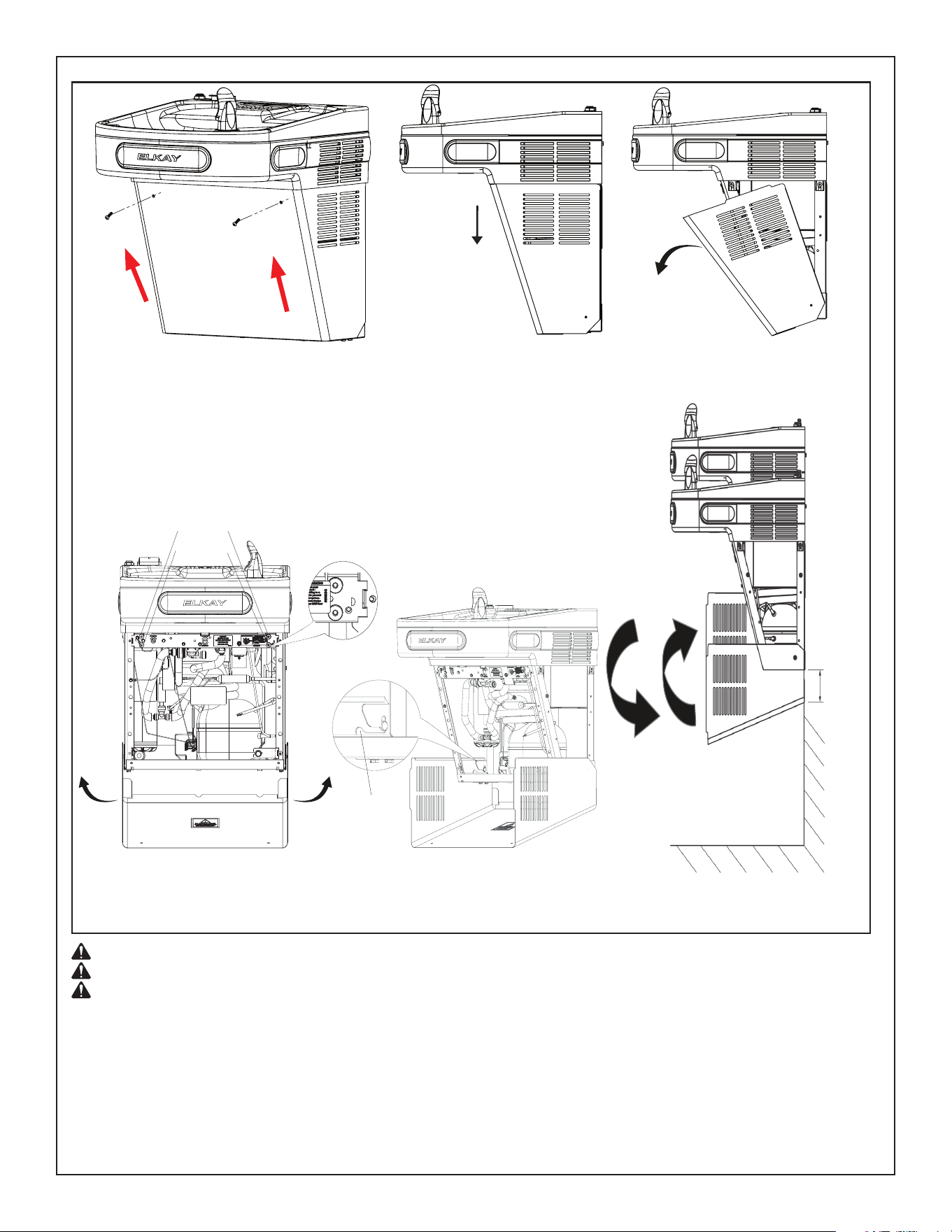
CAUTION: WRAPPER DROPS AND SWINGS WHEN SECURITY SCREWS ARE REMOVED.
CAUTION: DO NOT LEAN ON WRAPPER.
CAUTION: DO NOT USE POWER TOOL TO TIGHTEN. DO NOT OVERTIGHTEN.
NOTE:
1. Ensure that there are no plumbing or external objects below the wrapper in the specied dimension.
The specied (3.27’’) minimum distance is required for the wrapper to swing out (see Fig D(iv)).
2. Removing the wrapper from the pivoting bracket when servicing the unit is recommended. The wrapper may be left in place for quick
serviceability (see Fig D(iii)).
3. When re-attaching wrapper, ensure each side of wrapper is engaged to pivoting bracket (see Fig D(v)).
4. Once the wrapper is in place, rotate wrapper up and under the shroud. Ensure thru holes on wrapper are aligned with plastic bushing threads
on the frame prior to engaging security screws. Ensure screw is angled relative to the ground and perpendicular to wrapper surface prior to
engagement. Hand tighten prior to using hand tool to avoid cross-threading.
5. Four plastic bushings are located in the cross brace of the frame. The lower two bushings align with wrapper holes and the top two bushings
are extras in case of replacement (see Fig D(iii)).
Fig. D(i)
Fig. D(ii)
Fig. D(iv)
Fig. D(iii)
INSTRUCTIONS FOR REMOVING WRAPPER
Extra Bushings
Bushings in use
1) Remove the two security screws (size T25) from the front panel. (see Fig D(i)).
NOTE: SCREW THREADS INTO BUSHING WHILE ANGLED. DO NOT ATTEMPT TO
THREAD SCREW INTO BUSHING HORIZONTALLY.
2) Gently pull the wrapper down and rotate the wrapper to a downward position
(see Fig D(ii)).
3) To remove the wrapper, hold each side and gently pull wrapper up and out of pivoting
bracket (see Fig D(iii)).
Fig. D(v)
Pivoting
Bracket
Page 6
ENLZSTL8WS_1G_PIVOT
2000001213 (Rev. C - 02/24)
3.27’’
(83mm)
INSTALLATION OF COOLER
4) Refer Fig D(i) to D(iv), Pg. 6 for wrapper removing instructions.
5) Hang only the refrigerated cooler on the hanger bracket. Be certain hanger bracket is properly in the slots on the cooler backs
as shown in Figures 1 (Pg. 2), 2 (Pg.3), 3 (Pg. 4), and 4 (Pg. 5).
6) Hang the non-refrigerated cooler on the hanger bracket. Be certain hanger bracket is engaged properly in the slots on the cooler backs as shown in
Figures 1 (Pg. 2), 2 (Pg. 3), 3 (Pg. 4), and 4 (Pg. 5).
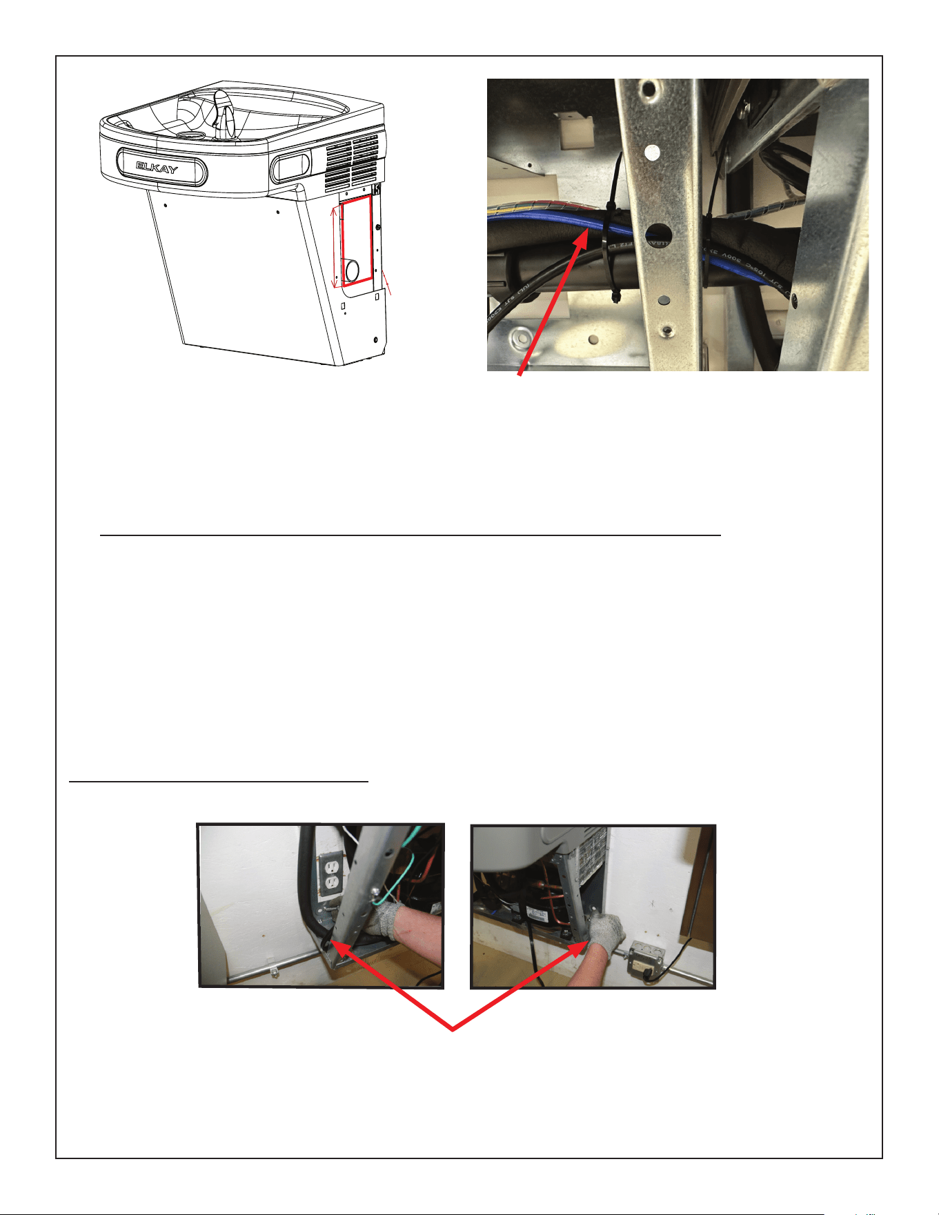
7) Unband the loose wires in the refrigerated cooler for the lter communication board. Stretch it out and thread through the left side of the
refrigerated cooler and into the right side of the non-refrigerated cooler. Plug into the lter communication board that is behind the lter head.
8) Secure each cooler frame to wall by installing (2) screws and washers (not supplied) in lower holes. See pictures below.
Make sure the screws engage in a structural member.
9) Connect the supply water to the lter 3/8” copper inlet tube.
10)Connect the waterline from the outlet of the lter to the inlet of the evaporator in the refrigerated cooler by inserting it into the quick connector.
11)Connect the waterline from the solenoid in the non-refrigerated cooler to the open 1/4” inch tee tting in the refrigerated cooler.
12)Find your cooler conguration on page 11 and connect the drain assembly together.
13)Install trap.
IMPORTANT: If it is necessary to cut the drain, loosen the screw at the black rubber boot and remove tube, check for leaks after re-assembly.
HANGER BRACKETS INSTALLATION
1) Remove hanger bracket fastened to back of coolers by removing one (1) screw.
2) Determine your mounting conguration from the gures shown on pages 2 - 5. Refrigeration unit must be on right hand side.
IMPORTANT NOTE: If the Bottle Filler is to be mounted on the left hand cooler, a basin assembly change will be needed.
Determine your conguration by referring to the Conguration Instructions on page 10 prior to continuing.
3) Mount the hanger bracket as shown in Figures 1 - 4 (Pages 2 - 5).
NOTE: Hanger Bracket MUST be supported securely. Add xture support carrier if wall will not provide adequate support. Anchor hanger
securely to wall using all six (6) 1/4 in. dia. mounting holes.
IMPORTANT: 5-7/8 in. (150 mm) dimension from wall to centerline of trap must be maintained for proper t.
FIG. 6
FIG. 7
Fig. F
NOTE:
To mitigate the wrapper rotation interferences, zip tie lines (plumbing and
electrical) running between the cooler units to the waste line (PVC pipe).
6.2
"
4
"
1
"
NOTE:
The highlighted portion in red color is acceptable plumbing rough-in for
installation.
Fig. E
Fig. F
Page 7 2000001213 (Rev. C - 02/24)
ENLZSTL8WS_1G_PIVOT
BOTTLE FILLER INSTALLATION
14) Remove two (2) mounting screws with 5/32” Allen wrench holding Bottle Filler to wall mounting plate (See Fig. 8). Note do not discard mounting
screws, they will be needed to secure Bottle Filler to wall mounting plate.
15) Remove wall mounting plate from Bottle Filler (See Fig. 8 ). Place wall mounting plate against wall on top of basin. Center the wall mounting plate side to
side with the basin. Mark the six (6) mounting holes with a pencil (See Fig. 1, Pg. 2). Place tape over wiring harness connection on top of cooler to
prevent debris from falling into Connection(See Fig. 6, Pg. 7).
16) Remove wall mounting plate from wall. NOTE: Mounting plate MUST be supported securely. Add xture support carrier if wall will not provide
adequate support.
17) Install wall mounting plate to wall using six (6) 7/16” obround mounting holes (mounting
bolts not included) (See Fig. 7, Pg. 7). Use appropriate fasteners for your wall type.
18) Install gasket on bottom of Bottle Filler with gasket support bracket & (2) screws.
(See Fig. 8).
FIG. 11
34
33
32
Gasket removed from bottle ller for clarity.
Mounting Bolt Holes
Walll Mounting Plate
Bottle Filling Unit
19) Route 3/8” tubing through the opening in the bottle ller gasket and plug into bulkhead tting in basin. Route the wiring harness through the
gasket and plug into the connector on the top of the basin. Water line should be cut to length prior to attaching to bulkhead tting.
20) Place Bottle Filler on the four (4) hooks on the mounting plate installed on wall.
FIG. 8
Fig. 10
Gasket removed from bottle ller for clarity.
Fig. 9
Page 8
ENLZSTL8WS_1G_PIVOT
2000001213 (Rev. C - 02/24)
INSTRUCTIONS TO ACCESS PROGRAMMING BUTTON
1) Remove lower cover on refrigerated unit by removing (2) screws.
2) Button is located in lower right corner of unit (See Fig. 13).
Programming
Button
FIG. 13
Front of Filter
FIG. 12
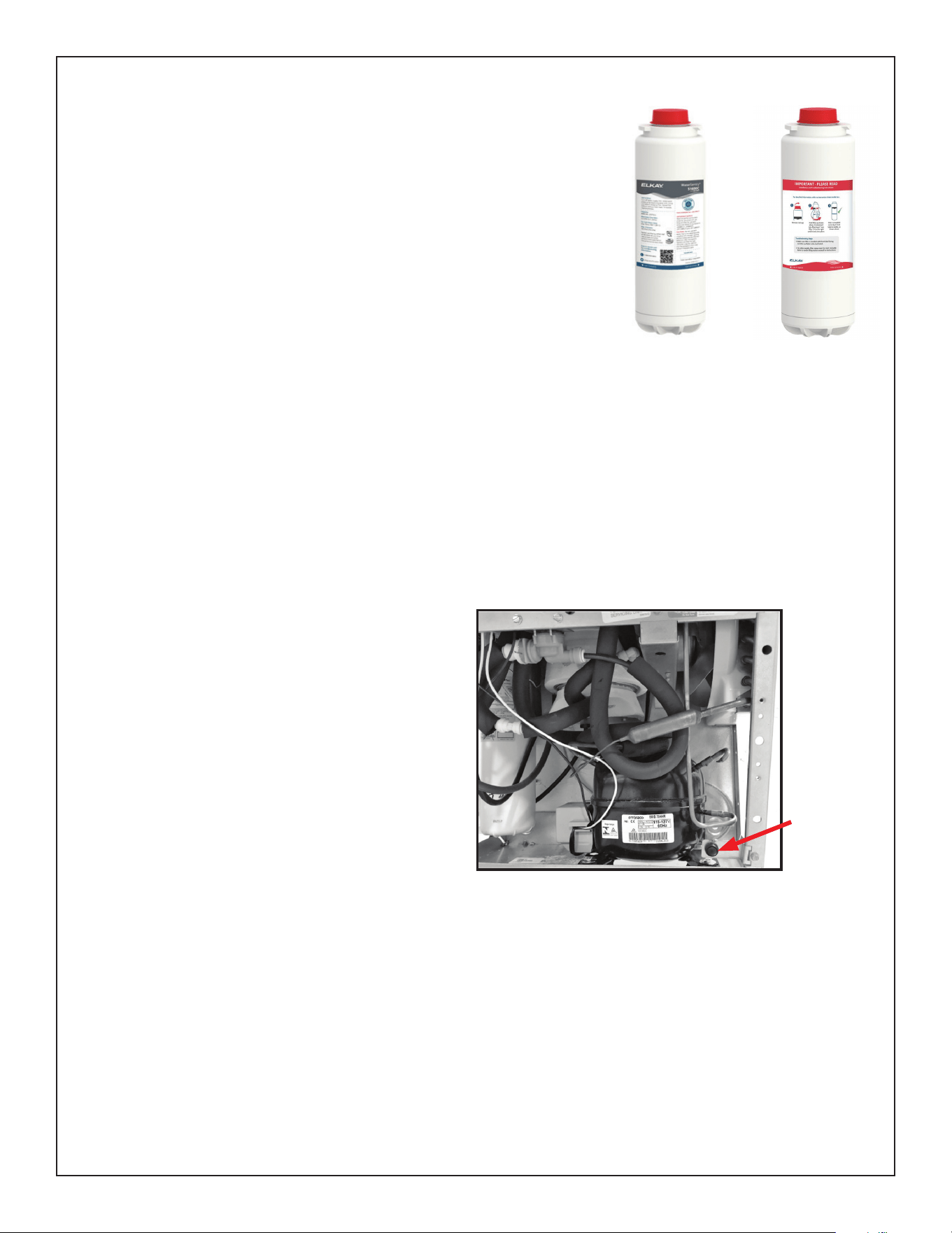
INSTRUCTIONS FOR REPLACING FILTERS
1) Refer Fig D(i) to D(iv), Pg. 6 for wrapper removing instructions.
2) Turn off water supply; dispense water to relieve pressure.
3) Remove power by unplugging cooler.
4) Turn used lter counterclockwise 1/4 turn to remove from lter head.
5) Remove cap from new lter and use to seal used lter.
6) Insert new lter into existing lter head and turn fully clockwise. Make sure you can read the label on the front of the lter once it is installed.
(See Fig. 12).
7) Plug in unit to restore power.
8) Turn on water supply and run water and ush lter to purge air and ne carbon particles from lter before use. Visit elkay.com/ltration for
additional details. Also run water through bottle ller until all air is removed and water ow is clear.
Note: Filter status light will automatically reset once new lter is installed.
FINAL INSTALLATION (FILTER)
21) Remove lter from carton, remove protective cap, attach lter to lter head by rmly in-
serting into head and rotating lter clockwise. Ensure that front facing label can be read
when lter is installed. (See Fig. 12)
22) Turn water supply on and inspect for leaks. In both cooler and Bottle Filler. Fix all leaks
before continuing.
23) Once cooler and bottle lter have been inspected for leaks and any leaks corrected,
plug cooler into wall.
24) Reinstall two mounting screws from rst step above. Caution do not over tighten screws.
25) Once power is applied to the cooler the GREEN LED light will illuminate on the bottle
ller showing good lter status along with the LCD Bottle Counter.
26) Verify proper dispensing by placing cup, hand, or any opaque object in front of sensor
area and verify that the water dispenses. Note: the rst initial dispenses might have air
in line which may cause a sputter and hazy appearance. Run water and ush lter to
purge air and ne carbon particles from lter before use. This will be eliminated when all
air is purged from the line.
27) Once unit tests out, install Lower Panels back on water coolers. (See pages 12-13 for
versatile wrapper installation).
28) When re-attaching wrapper, push wrapper up and under the shroud. Make sure wrapper
and bushing holes are aligned prior to inserting screw. Units are now ready for use.
Back of Filter
Page 9 2000001213 (Rev. C - 02/24)
ENLZSTL8WS_1G_PIVOT
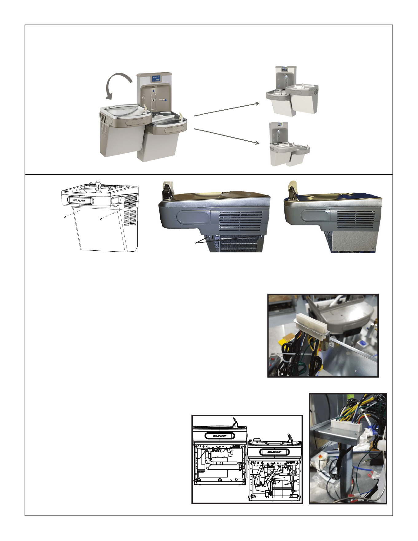
FIG. 14
FIG. 15 FIG. 16
Page 10
ENLZSTL8WS_1G_PIVOT
2000001213 (Rev. C - 02/24)
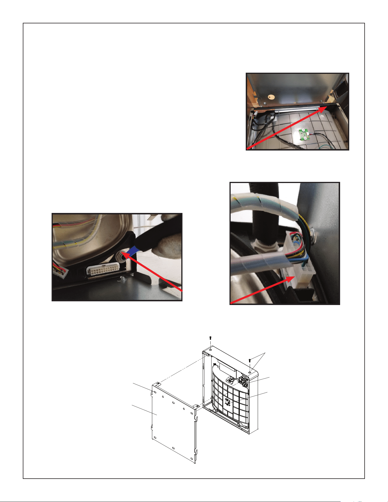
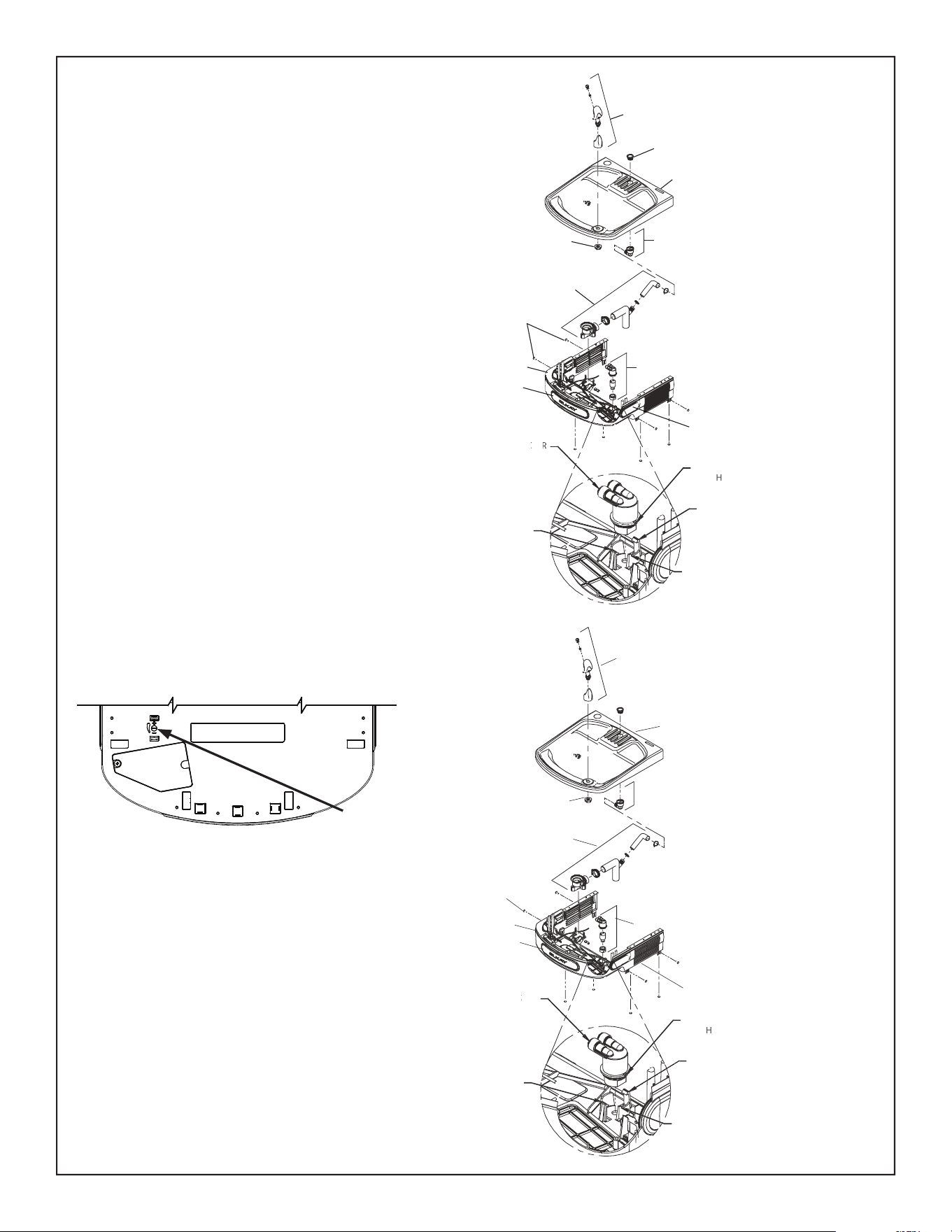
1. Refer Fig D(i) to D(iv), Pg. 6 for wrapper removing instructions.
2. Remove ller panel from cooler using a 5/16” socket.
3. Using a T25 (6-point star) bit, loosen the shroud screws on both sides of both coolers.
4. Lift the basin/shroud assembly from each cooler. Disconnect the water line from the
solenoid and the shroud wires from the wiring harness and solenoid. Set aside.
5. Unfasten the electrical harness connector from the electrical bracket.
Using a T25 (6-point star) bit, remove the electrical bracket from the mounting bracket.
Snap the electrical harness connector into the cutout of the mounting bracket with the
connector facing down. (See Fig 14.)
6. Install the electrical bracket on the lter bracket of the non-refrigerated cooler
by removing the two screws towards the front of the cooler and reinstalling them
through the bracket. Attach the female end of the bi-level extension into the
electrical bracket.
7. Only move the ller panel and J-clip to the refrigerated (right) cooler if the right
side will be mounted high.
8. Install the non-bottle ller basin on the refrigerated cooler. Connect the water line
to the solenoid and the electrical connections to the wiring harness and solenoid.
Tighten the (4) T25 screws.
9. Mount the refrigerated cooler on the right-hand hanger bracket. Secure to wall.
10. Install the bottle ller basin on the non-refrigerated cooler. Connect
the water line to the solenoid and the electrical connections
to the wiring harness and solenoid. Be certain the
electrical connector is protruding through the cutout
in the top of the basin. Tighten the (4) T25 screws.
11. Mount the non-refrigerated cooler on the left-hand
hanger bracket. Secure to wall.
12. Route the bi-level extension through the coolers and
connect to the refrigerated electrical harness mounted
in the mounting bracket (See Figs. 15 & 16).
13. Hook up the drains using the attached drain kit.
14. Make all water and electrical connections.
15. Reinstall wrappers using (2) screws for each wrapper.
CONFIGURATION INSTRUCTIONS
INSTRUCTIONS TO MOVE THE BOTTLE FILLER & BASIN TO THE LEFT SIDE
(NON-REFRIGERATED) FOR ALTERNATE MOUNTING VERSATILE BI-LEVEL
ONLY move the ller panel and j-clip
to the refrigerated (right) side if right
side will be mounted “high”
Fig. A
Fig. B Fig. C
Page 11 2000001213 (Rev. C - 02/24)
ENLZSTL8WS_1G_PIVOT
FIG.17
FIG.18
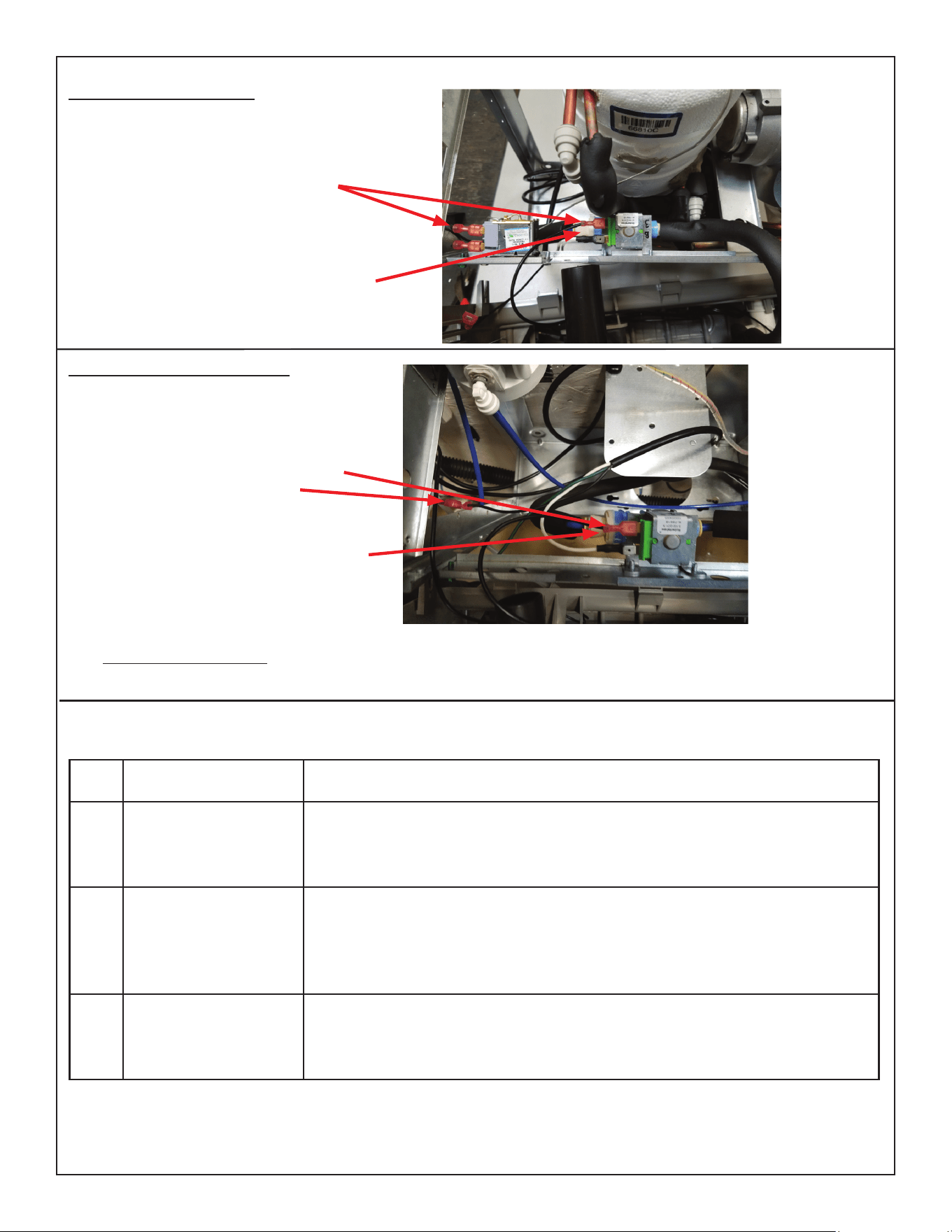
Swap drain parts in shroud: Loosen each hose clamp retaining the drain pieces. Remove each drain piece and swap to other basin.
Tighten each hose clamp.
Non-Refrigerated Cooler side:
Carefully tip the shroud/basin assembly
toward the cooler frame.
Connect one of the black wires to the
solenoid valve and one to the power
cord.
Re-connect the water line at the
solenoid. Reference (See Fig. 20, Pg.15)
for the operation of the quick connect
ttings.
Refrigerated Cooler side:
Carefully lift and tip the shroud/basin
assembly off the cooler frame.
Only disconnect the (2) black wires
coming from the shroud assembly that
go to the solenoid valve and to the cold
control.
Disconnect the water line at the solenoid
valve. Reference (See Fig. 20, Pg.15)
for the operation of the quick connect
ttings.
Enhanced EZH2O Error Codes
Error
Code
Error Description Corrective Action
Please clear Bottle Filler • Remove obstruction
• Clean lens on IR sensor
• Unplug unit for at least 30 seconds and restart
• If error repeats, replace IR sensor
E013 Missing or Incompatible Filter • Check that lter is installed correctly (label facing forward, round blue tag facing NFC Board)
• Unplug unit for at least 30 seconds and restart
• Replace lter
• Replace lter head assembly with repair kit
• If error repeats, contact certied service professional
EO13
&
EO14
Missing/Unplugged NFC
Board
• Unplug unit for at least 30 seconds and restart
• Verify cable connector is plugged into NFC board on lter head assembly
• Replace lter head assembly with repair kit
• If error repeats, contact certied service professional
Page 12
ENLZSTL8WS_1G_PIVOT
2000001213 (Rev. C - 02/24)
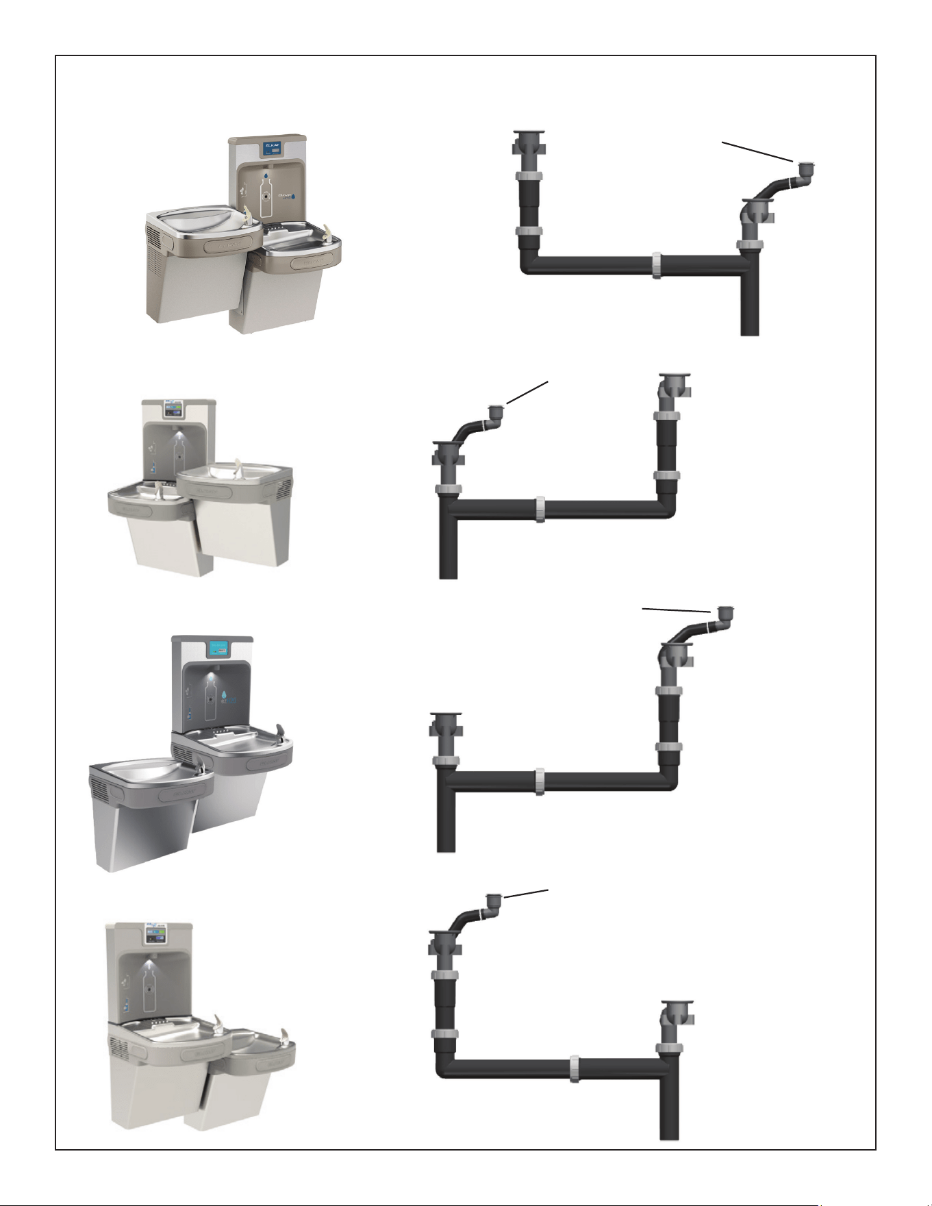
PLUMBING DIAGRAMS
VERSATILE BI-LEVEL
Bottle Filler
Drain
Bottle Filler
Drain
Bottle Filler
Drain
Bottle Filler
Drain
Page 13 2000001213 (Rev. C - 02/24)
ENLZSTL8WS_1G_PIVOT
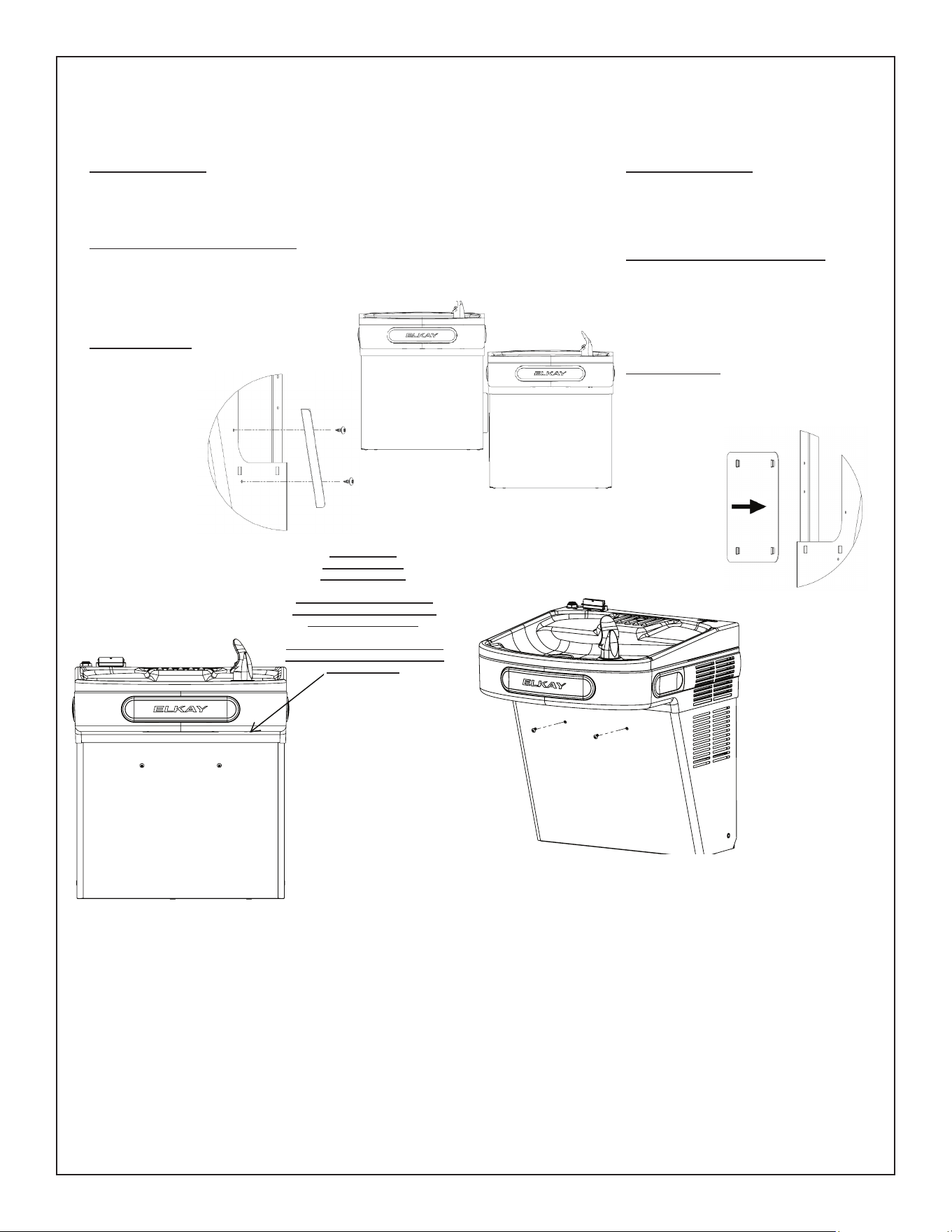
Versatile Wrapper and Trim Kit Installation Instructions
Right Hand Wrapper (Low Side)
1) Remove the (2) screws from the wrapper,
rotate the wrapper down, and remove.
2) Clip cover plate, sliding until plate sits ush
with the wall.
3) Re-install wrapper with (2) screws.
4) Dispose of unused trim piece.
Revestimiento del lado derecho (Lado
bajo)
1) Retire los (2) tornillos del envoltorio, gire el
envoltorio hacia abajo, y quitar.
2) Sujete la placa de la cubierta, deslizándola
hasta que quede alineada con la pared.
3) Vuelva a instalar el revestimiento con los (2)
tornillos.
4) Deseche la pieza de acabado que no usa.
Enveloppe droite (côté gauche)
1) Retirez les (2) vis de l’emballage, faites
pivoter l’emballage vers le bas, et
supprimer.
2) Encliqueter la plaque de fermeture, en
la glissant
jusqu’au ras du
mur.
3) Remonter
l’enveloppe
avec quatre (2)
vis.
4) Jeter la pièce
de garniture
inutilisée.
Left Hand Wrapper (High Side)
1) Remove the (2) screws from the wrapper, rotate the wrapper down,
and remove.
2) Screw trim piece to wrapper with (2) screws (provided).
3) Re-install wrapper with (2) screws.
4) Dispose of unused cover plate.
Revestimiento del lado izquierdo (Lado alto)
1) Retire los (2) tornillos del envoltorio, gire el envoltorio hacia abajo,
y quitar.
2) Atornille la pieza de acabado al revestimiento con los (2) tornillos
(proporcionados)
3) Vuelva a instalar el revestimiento con los (2)
tornillos.
4) Deseche la placa de la cubierta que no usa.
Enveloppe gauche (côté haut)
1) Retirez les (2) vis de l’emballage, faites pivoter
l’emballage vers le bas, et supprimer.
2) Visser la pièce
de garniture à
l’enveloppe avec
deux (2) vis
(fournies)
3) Remonter
l’enveloppe avec
quatre (2) vis.
4) Jeter la plaque
de fermeture
inutilisée.
Wrapper Fill
Piece Location
(Left Side High)
Ubicación de la pieza de
llenado del recubrimiento
(lado izquierdo alto)
Emplacement de la pièce de
fermeture d’enveloppe (côté
gauche haut)
Page 14
ENLZSTL8WS_1G_PIVOT
2000001213 (Rev. C - 02/24)
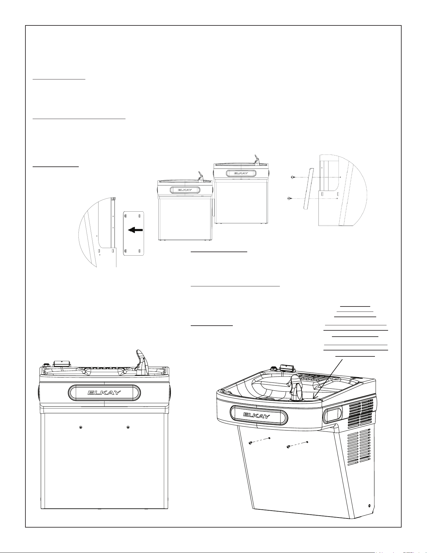
Left Hand Wrapper (Low Side)
1) Remove the (2) screws from the wrapper, rotate
the wrapper down, and remove.
2) Clip cover plate, sliding until plate sits ush with
the wall.
3) Re-install wrapper with (2) screws.
4) Dispose of unused trim piece.
Revestimiento del lado izquierdo (Lado bajo)
1) Retire los (2) tornillos de la envoltura, gírela hacia
abajo y retírela.
2) Sujete la placa de la cubierta, deslizándola hasta
que quede alineada con la pared.
3) Vuelva a instalar el revestimiento con los (2)
tornillos.
4) Deseche la pieza de acabado que no usa.
Enveloppe gauche (côté bas)
1) Retirez les (2) vis de l’emballage, faites pivoter
l’emballage vers le bas, et supprimer.
2) Encliqueter la plaque de fermeture, en la glissant
jusqu’au ras du mur.
3) Remonter l’enveloppe avec quatre (2) vis.
4) Jeter la pièce
de garniture
inutilisée.
Right Hand Wrapper (High Side)
1) Remove the (2) screws from the wrapper, rotate the
wrapper down, and remove.
2) Screw trim piece to wrapper with (2) screws (provided)
3) Re-install wrapper with (2) screws.
4) Dispose of unused cover plate.
Revestimiento del lado derecho (Lado alto)
1) Retire los (2) tornillos de la envoltura, gírela hacia
abajo y retírela.
2) Atornille la pieza de acabado al revestimiento con los
(2) tornillos (proporcionados)
3) Vuelva a instalar el revestimiento con los (4) tornillos.
4) Deseche la placa de la cubierta que no usa.
Enveloppe droite (côté haut)
1) Retirez les (2) vis de l’emballage, faites pivoter
l’emballage vers le bas et retirez-le.
2) Visser la pièce de garniture à l’enveloppe avec deux
(2) vis (fournies)
3) Remonter l’enveloppe avec quatre (4) vis.
4) Jeter la plaque de fermeture inutilisée.
Wrapper Fill
Piece Location
(Right Side High)
Ubicación de la pieza de
llenado del recubrimiento
(lado derecho alto)
Emplacement de la pièce
de fermeture d’enveloppe
(côté droit haut)
Versatile Wrapper and Trim Kit Installation Instructions continued. . .
Instrucciones de instalación versátiles de la envoltura y del juego de molduras continuadas. . .
Instructions d’installation du kit d’emballage et de garniture polyvalentes (suite). . .
115V Refrigerated Wiring Diagram
with Alpha/Numeric Display
24
36
Fig. 19
37
25
26
Fig. 20
A
B CA
SIMPLY PUSH IN
TUBE TO ATTACH
TUBE IS SECURED
IN POSITION
PUSH IN COLLET
TO RELEASE TUBE
OPERATION OF QUICK CONNECT FITTINGS
PUSHING TUBE IN BEFORE
PULLING IT OUT HELPS TO
RELEASE TUBE
OPERATION OF QUICK CONNECT FITTINGS
SIMPLY PUSH IN
TUBE TO ATTACH
TUBE IS SECURED
IN POSITION
PUSH IN COLLET
TO RELEASE TUBE
B C
34
32
35
LZSTL8WSSP (Bi-level)
LZSTL8WSSP-PF (Bi-level)
WARNING
• INGESTION HAZARD: This product contains a button cell or coin battery.
• DEATH or serious injury can occur if ingested.
•A swallowed button cell or coin battery can cause Internal Chemical
Burns in as little as 2 hours.
• KEEP new and used batteries OUT OF REACH of CHILDREN
• Seek immediate medical attention if a battery is suspected to be
swallowed or inserted inside any part of the body.
Page 15 2000001213 (Rev. C - 02/24)
ENLZSTL8WS_1G_PIVOT
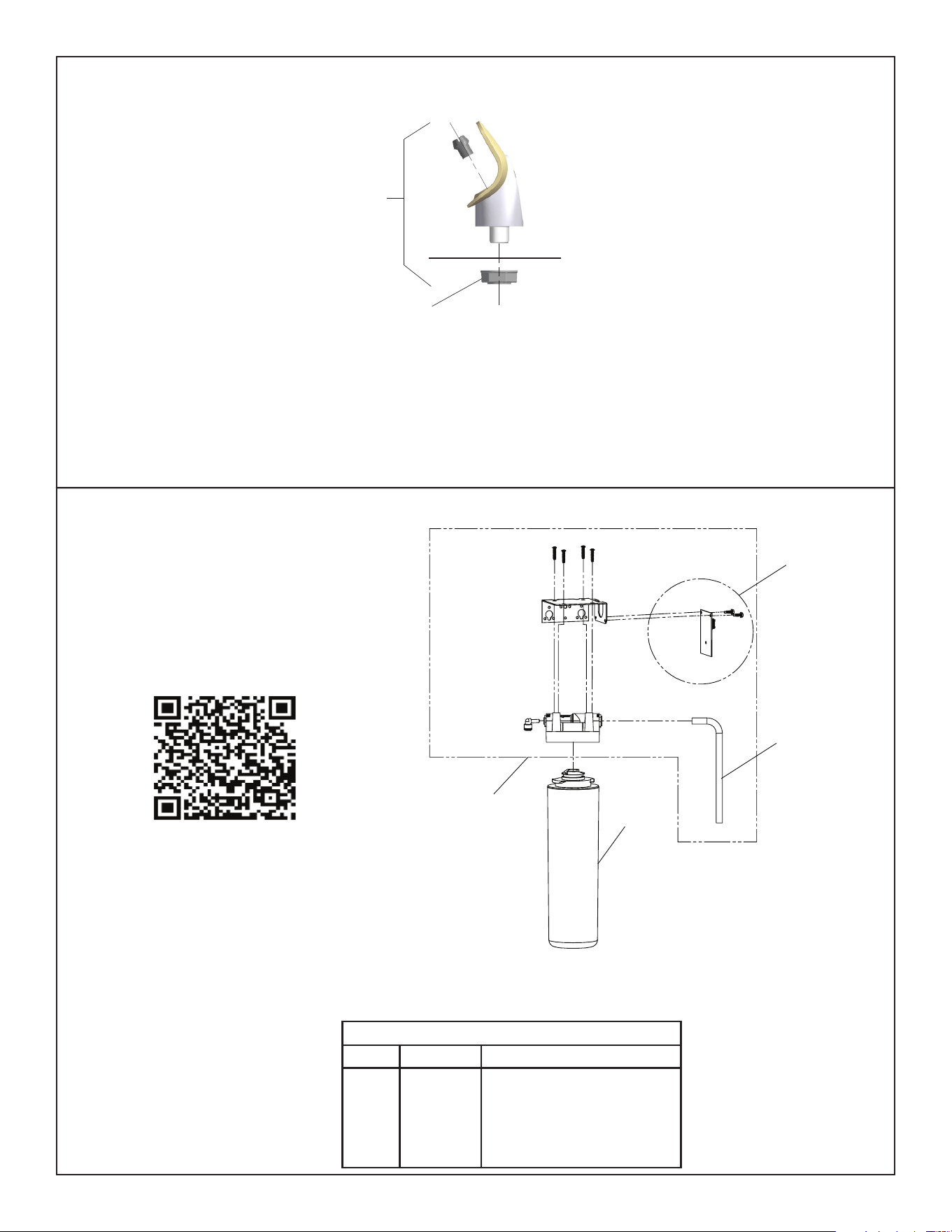
WATERSENTRY
®
Filter Detail
NOTE:
When installing replacement bubbler and pedestal, tighten
nut only to hold parts snug in position. Do Not Overtighten.
11
Fig. 21
Basin
Locknut
Fig. 22
BUBBLER DETAIL
DESCRIPTIONITEM NO. PART NO.
WATERSENTRY
®
FILTER PARTS LIST
Filter 3000 Gal (standard)
Filter 6000 Gal (high capacity)
Filter 2250 Gal (PFOA/PFAS)
Kit - Filter Head Fittings includes
John Guest Fittings & 3/8” Elbow
Filter Bracket/Screws
Kit - NFC Board/Cover
51300C
51600C
71300C
1000005214
1000004409
1
2
3
4
5
3/8”
Water
Inlet
1 or 2
or 3
4
5
Scan for trouble shooting and to sign up for
auto replenishment of authentic Elkay lters.
Page 16
ENLZSTL8WS_1G_PIVOT
2000001213 (Rev. C - 02/24)
REGULA
TO
REGULATOREGULA
ASSEMB
LY
ALIGNMENT
NO
TC
H
ALIGNMENT
PEG
SNAP
SNAP
Service Instructions
Lower and Upper Shroud
To access the refrigeration system and plumbing connections, remove two (2) screws from front
of cooler to remove the lower shroud. To remove the upper shroud for access to the pushbars,
regulator, solenoid valve or other components located in the top of the unit, remove lower shroud,
disconnect drain, remove four screws from tabs along lower edge of upper shroud, unplug two
wires and water tube.
Bubbler
To remove the bubbler, rst disconnect the power supply. The underside of the bubbler can be
reached through the access panel on the underside of the upper shroud. Remove the access
panel by removing the retaining screw. To remove the bubbler, loosen locknut from the underside
of the bubbler and remove the tubing from the quick connect tting per the Operation Of Quick
Connect Fittings section in the General Instructions. After servicing, replace the access panel
and retaining screw.
Switches Behind the Push Bar
The regulator in an EZ cooler is always held fully open by the use of a single regulator nut.
Water is not dispensed until the pushbar is depressed to activate a switch which then opens a
solenoid valve.
To remove sidebars, from the inside compress the ared tabs and pull out carefully. To reinstall
side pushbars, the front of the pushbar is inserted rst. While keeping the switch depressed,
snap the rear of the pushbar into position.
Cleaning
Stainless Steel
• General cleaning: use an ordinary mild detergent and soft cloth, rinse and towel dry.
• Steel soap pads should never be used; particles can adhere to a stainless steel basin
surface and will eventually rust.
• Light scratches are normal for stainless steel basins; over time they will blend into the
uniform nish pattern.
• Do not use cleaners containing acids or chlorides, these will cause the stainless steel to
oxidize.
Plastic Components
• General cleaning: use an ordinary mild detergent and soft cloth, rinse and towel dry.
• Wiping the surface clean to remove debris or build up will not hurt the antimicrobial
properties.
Temperature Control
• Factory set at 50°F (+/- 5°F) under normal conditions. For altitude adjustments, refer to
sticker on left side of top bar.
Stream Height Adjustment
VIEW OF UNDERSIDE OF BASIN SHROUD
Stream Height Adjustment Location
11
12,13
6
28A
20
12
11
29
29
2B
10
Page 17 2000001213 (Rev. C - 02/24)
ENLZSTL8WS_1G_PIVOT
REGULA
TO
REGULATOREGULA
R
ASSEMB
LY
ALIGNMENT
NO
TC
H
ALIGNMENT
PEG
SNAP
SNAP
Fig. 23
Fig. 24
11
28B
12
6
12,13
20
2A
11
10
Refrigerated Unit
Non-Refrigerated Unit
Programming Instruction
Depress Button for 3 seconds to activate main menu - release
Cycles thru main menu items 2 seconds each for 2 cycles then exits menu unless selected
Cycles thru sub menu items 2 seconds each for 2 cycles then returns to main menu unless selected
Selections are saved when the menu is exited
Top
level
Action Sub Menu 1 Action Sub Menu/action Action Sub Menu/
action
Action Sub Menu/
action
Notes End Action
Info Momentary Scrolls through all the settings
on unit
Returns to Main Menu
Info Momentary Flashes error code Returns to Main Menu
Set time Momentary Drops to next level when selected
Day (Sunday-Saturday Momentary Use push button to select the day on the display Drops to next level when selected
AM/PM Momentary Use push button to select AM or PM Drops to next level when selected
Hour (12 hour) Momentary Use push button to select Hour Drops to next level when selected
Min 0-69 in 5 minute incre-
ments
Momentary Use push button to select closest minute Returns to Main Menu
Filter Momentary Drops to next level when selected
No Momentary Turn off lter status and errors No Filter unit - Error codes related to lter status
turned off
Returns to Main Menu
Yes Momentary Default setting - Turn on lter status and errors Filter status has default ON / Default has read
write to lter, LED status display, lter error
capability
Returns to Main Menu
Refrig Momentary Drops to next level when selected
No Momentary Disables E/S relay sets bottle ll time to 1.5gpm Refrigeration off Returns to Main Menu
Yes Momentary Default setting - Enables E/S relay - sets time to 1.1gpm Refrigeration on Returns to Main Menu
Range Momentary The lower the number, the closer to the sensor the
bottle needs to be to activate
Drops to next level when selected
1-10 Momentary Default setting 5 - Adjusts distance from sensor the bottle
needs to be before turning before turning on or off the bottle
ller
Returns to Main Menu
B-Light Momentary The settings are for the brightness of the display
and night light
Drops to next level when selected
25% Momentary Returns to Main Menu
50% Momentary Returns to Main Menu
75% Momentary Default Setting Returns to Main Menu
100% Momentary Returns to Main Menu
EnerSave Momentary Drops to next level when selected
Off Momentary Default Setting Returns to Main Menu
On Momentary Set Energy Save Schedule Drops to next level when selected
Select
Weekday
Drops to next level when selected
Momentary Select time on 24 hours – 1-12AM and 1-12PM Drops to next level when selected
Momentary Select time off 24 hours – 1-12AM and 1-12PM Drops to next level when selected
Select Week-
end
Drops to next level when selected
Momentary Select time on 24 hours – 1-12AM and 1-12PM Drops to next level when selected
Momentary Select time off 24 hours – 1-12AM and 1-12PM Returns to Main Menu
Page 18
ENLZSTL8WS_1G_PIVOT
2000001213 (Rev. C - 02/24)
Page 19 2000001213 (Rev. C - 02/24)
ENLZSTL8WS_1G_PIVOT
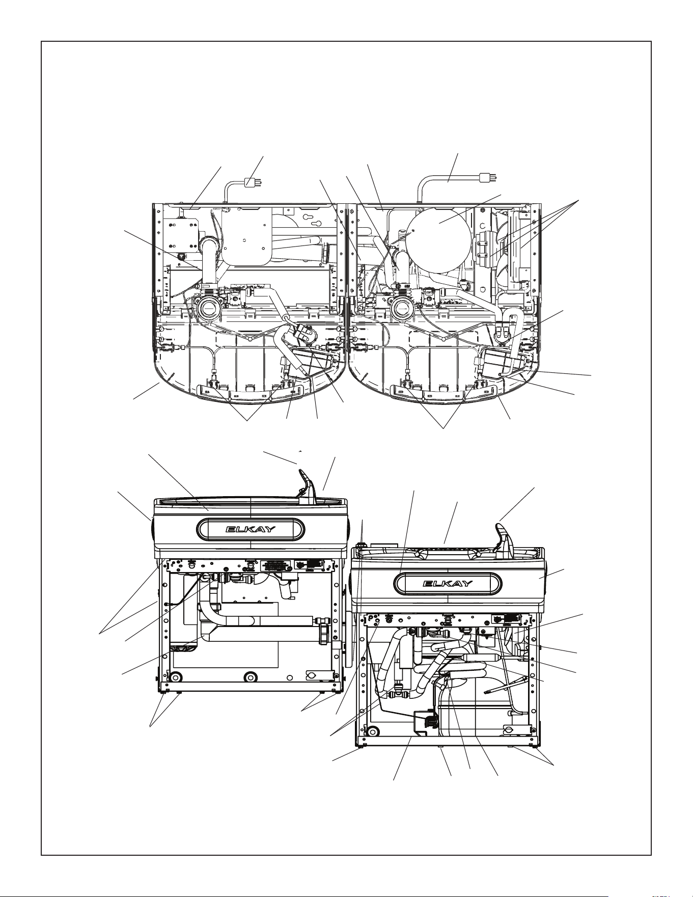
Pictured is unit only without bottle ller.
Note: Danger! Electrical shock hazard. Disconnect power before servicing unit.
20
27
1
See Fig. 23
2A
14
12
20
12, 13
20
4
27
20
See Fig. 24
17
2B
15
12
3
6
Fig. 25
20
19
20
28B
22
1
16
12, 13
5
3
6
5
18
21
7
23
Uses HFC-134A refrigerant
Usa refrigerante HFC-134A
Utilise du uide frigorigéne HFC-134A
10
9
31
8
9
10
8
28A
30
*COMPREND RELAIS ET LIMITEUR DE SURCHARGE. SI SOUS
GARANTIE, REMPLACÉ PAR LE MÊME COMPRESSEUR QUE
CELUI DE L’APPAREIL D’ORIGINE.
REMARQUE : Toute correspondance concernant toute fontaine
à eau fraîche ci-dessus ou toute commande de pièces détachées
devra IMPÉRATIVEMENT inclure le numéro de modèle et le numéro
de série de l’appareil, ainsi que le nom et le numéro de pièce des
pièces de rechange.
*INCLUDES RELAY & OVERLOAD. IF UNDER
WARRANTY, REPLACE WITH SAME COMPRESSOR
USED IN ORIGINAL ASSEMBLY.
NOTE: All correspondence pertaining to any of the
above water coolers or orders for repair parts MUST
include Model No. and Serial No. of cooler, name and
part number of replacement part.
*INCLUYE RELÉ Y SOBRECARGA. SI ESTÁ CUBIERTO POR LA
GARANTÍA, REEMPLACE CON EL MISMO COMPRESOR QUE SE
USA EN EL CONJUNTO ORIGINAL.
NOTA: Toda la correspondencia que guarde relación con los bebedores
descritos anteriormente, o los pedidos de piezas de repuesto, DEBEN
incluir el n.° de modelo y el n.° de serie del bebedero, nombre y número
de pieza del repuesto.
ITEM NO. PART NO.
DESCRIPTION DESCRIPCIÓN
DESCRIPTION
Soporte colgante
Tarja: Acero inoxidable
Tarja: Llenadora de botellas de acero inoxidable
Cableado: Barra de empuje delantera y lateral
Compresor: Paquete de servicio de 115 V EMIS70HHR
Tubería: Polietileno (corte a la longitud necesaria)
Conjunto; recubrimiento; superior (Empuje delantero y lateral)
Secador
Panel de acceso
Kit - Conjunto de válvula solenoide / regulador
Kit regulador con soporte y tuerca
Conjunto de burbujas de repuesto
Kit: Barra de empuje (Delantera y lateral) TL
Kit: Barra de empuje (Solo delantera)
Kit: Cable electrico L/R
Cable Electrico EZTL8
Kit: Motor del ventilador, aspa, tornillos y tuerca
Kit: Condensador/secador/lazos de alambre
Kit: Piezas metálicas de montaje del compresor, arandelas,
sujetadores y remaches
Kit: Intercambiador de calor y secador
Kit: Piezas metálicas
Kit: Eléctrico, relé, sobrecarga y cubierta
Kit: Repuesto evaporador
Kit: 75583C Codo 5/16" x 1/4" (Paquete de 3)
Arnés - Enfriador
Cable - Puente de 6 “
Asamblea de alambre - Puente
Conjunto de tubería de desagüe BF
Kit: Repuesto de desagüe TL
Kit: Repuesto de desagüe (TL) LR
Kit: Desague de la llenadora de botellas
Kit - Panel: (Recubrimiento) acero inoxidable TL
Kit - Panel: (Revestimiento): Acero inoxidable LZTLD
Llenadora: Revestimiento gris claro LZTLD
Llenadora: Revestimiento acero inoxidable LZTLD
Soporte: Banda de acabado gris claro LZTLD
Soporte: Banda de acabado acero inoxidable LZTLD
Panel: Banda universal gris claro LZTLD
Panel: Banda universal acero inoxidable LZTLD
Ferrure de suspension
Cuve - Acier inoxydable
Cuve - Remplisseuse de bouteille en acier inoxydable
Câblage - Poussoir frontal/latéral
Compr - Ens. service 115 V EMIS70HHR
Tube - Poly (couper à la longueur)
Carénage supérieur (poussoir frontal/latéral)
Déshydrateur
Panneau d’accès
Kit - Assemblage électrovanne / régulateur
Kit régulateur avec support et écrou
Asss de remplacement Bubbler
Trousse - Poussoir (frontal/latéral) TL
Trousse - Poussoir (frontal seulement)
Cordon d’Alimentation L/R
Cordon d’Alimentation EZTL8
Trousse - Moteur de ventilateur/pales/vis/écrou
Trousse - Statiques/sécheur/Colliers
Trousse - Visserie x. compr./œillets/clips/goujons
Trousse - Échangeur chaleur/déshydrateur
Trousse - Visserie
Trousse - Élect./relais/antisurcharge/capot
Trousse - Évaporateur de rechange
Trousse - 75583C Coude 5/16 po x 1/4 po (paq. 3)
Harnais - Glacière
Fil - Cavalier de 6 ”
Assemblage de ls - Cavalier
Écoulement conduite eau usée BF
Trousse - Écoulement de rechange TL
Trousse - Écoulement de rechange (TL) LR
Trousse - Ecoulement remplisseuse de bouteille
Trousse - Panneau (Enveloppe) Acier inoxydable TL
Trousse - Panneau (Enveloppe) Acier inoxydable LZTLD
Remplisseuse - Enveloppe gris clair LZTLD
Remplisseuse - Enveloppe inox LZTLD
Attache - Bande de garniture gris clair LZTLD
Attache - Bande de garniture inox LZTLD
Panneau - Garniture universelle gris clair LZTLD
Panneau - Garniture universelle inox LZTLD
28401C
55001109
0000001337
36216C
36322C
56092C
56229C
66703C
56213C
1000004572
1000004564
56073C
98734C
1000001600
35980C
1000004568
98775C
98776C
98777C
98778C
98898C
0000000238
98724C
1000001602
1000004547
1000004550
1000004559
1000004447
98900C
97969C
1000001812
98773C
2000001267
2000001274
28024C
28025C
1000001892
1000001891
1000001894
1000001893
Hanger Bracket
Basin - Stainless Steel
Basin - Bottle Filler Stainless Steel
Wiring - Front/Side Push Bar
Compr - Service Pak 115V EMIS70HHR
Tube - Poly (Cut To Length)
Assy - Shroud - Upper (Front Side Push)
Drier
Access Panel
Kit - Solenoid Valve/Regulator Assembly
Kit - Regulator W/Holder & Nut
Replacement Bubbler Assy
Kit - Pushbar (Front/Side) TL
Kit - Pushbar (Front Only)
Power Cord Non-Refrigerated
Power Cord - EZTL8
Kit - Fan Motor/Blade/Screws/Nut
Kit - Condenser/Drier/WireTies
Kit - Compr Mtg Hdwe/Grommets/
Clips/Studs
Kit - Heatx/Drier
Kit - Hardware
Kit - 115V Electricals (Relay, Ovrld, Cover)
Kit - Evap. Replacement
Kit - 75583C Elbow 5/16" x 1/4" (3 Pack)
Harness - Cooler
Wire - 6” Jumper
Wire Assy - Jumper
Wasteline Drain Assy
Kit - Drain Replace TL
Kit - Drain Replace (TL) LR
Kit - Bottle Filler Drain
Kit - Cold Control
Kit - Drop Down Wrapper Stainless TL
Kit - Drop Down Wrapper Stainless LZTLD
Filler - Wrapper Light Grey LZTLD
Filler - Wrapper Stainless LZTLD
Bracket - Trim Strip Light Grey LZTLD
Bracket - Trim Strip Stainless LZTLD
Panel - Universal Trim Light Grey LZTLD
Panel - Universal Trim Stainless LZTLD
1
2A
2B
3
*4
5
6
7
8
9
10
11
12
13
14
15
16
17
18
19
20
21
22
23
24
25
26
27
28A
28B
29
30
NS
NS
NS
NS
BOTTLE FILLER REPLACEMENT PART KITS
KITS DE PIEZAS DE REPUESTO DE LA LLENADORA DE BOTELLAS
TROUSSES DE PIÈCES DE RECHANGE POUR LA REMPLISSEUSE DE BOUTEILLE
NS
31
32
NS
33
34
35
NS
36
37
ITEM NO.
PART NO. DESCRIPTION DESCRIPCIÓN
DESCRIPTION
98546C
98549C
1000004573
1000005077
1000002433
1000005219
1000004544
1000004436
1000004546
1000004549
Kit - Aerator Replacement
Kit - Hardware & Waterway (BF)
Kit - Solenoid Valve 120V (BF)
Nameplate - Elkay Filtered
Kit - Top Cover Assy (BF)
Kit - IR Sensor K+
Kit - Alpha Numeric LED Board
Kit - Tower/Basin Gasket
Harness - Bottle Filler
Harness - LED/IR Board
Kit: Repuesto de aireador
Kit: Piezas metálicas y canales (LlB)
Kit - Conjunto de válvula solenoide
Placa de identicación: Elkay con ltro
Kit: Conjunto de cubierta superior (LlB)
Kit: Sensor infrarrojo
Kit: Panel LED alfanumérico
Kit: Torre y empaquetadura de la tarja
Arnés - Llenadora de botellas
Arnés - Tablero LED/IR
Trousse - Aérateur de rechange
Trousse - Visserie et circuit d’eau (RB)
Kit - Assemblage électrovanne
Plaque signalétique - Elkay à ltre
Trousse - Capot supérieur (RB)
Trousse - Capteur IR
Trousse - Carte voyant alphanumérique
Trousse - Joint tour/fontaine
Harnais - Remplisseur De Bouteille
Harnais - Carte LED/IR
NS = Not Shown
NS = No se muestra
NS = Non représenté
NS = Not Shown
115V PARTS LIST / LISTA DE PIEZAS DE 115 V / LISTE DES PIÈCES 115 V
Page 20
ENLZSTL8WS_1G_PIVOT
2000001213 (Rev. C - 02/24)
ATTENTION:
If the product serial number is before 190424189, please refer to archived documents section of Elkay.com for the most accurate
parts list. (www.elkay.com/archived-documents)

FCC COMPLIANCE STATEMENT
CAUTION: Changes or modications not expressly approved could void your authority to use this equipment
This device complies with Part 15 of the FCC Rules. Operation to the following two conditions: (1) This device may not cause harmful interference, and (2) this device must
accept any interference received, including interference that may cause undesired operation
INDUSTRY CANADA STATEMENT
This device complies with Industry Canada license-exempt RSS standard(s). Operation is subject to the following two conditions: (1) this device may not cause interference,
and (2) this device must accept any interference, including interference that may cause undesired operation of the device.
Le présent appareil est conforme aux CNR d’Industrie Canada applicables aux appareils radio exempts de license. L’exploitation est autorisée aux deux conditions
suivantes : (1) l’appareil ne doit pas produire de brouillage, et (2) l’utilisateur de l’appareil doit accepter tout brouillage radioélectrique subi, même si le brouillage est
susceptible d’en compromettre le fonctionnement.
PRINTED IN U.S.A.
IMPRESO EN LOS E.E.U.U.
IMPRIMÉ AUX É.-U.
ELKAY MANUFACTURING Co. • 1333 BUTTERFLIED ROAD SUITE 200 DOWNERS GROVE, IL 60515 USA - • 630.574.8484 • www.elkay.com
FOR PARTS, CONTACT YOUR LOCAL DISTRIBUTOR OR CALL 1.800.834.4816
PARA PIEZAS, CONTACTE A SU DISTRIBUIDOR LOCAL O LLAME AL 1.800.834.4816
POUR OBTENIR DES PIÈCES, CONTACTEZ VOTRE DISTRIBUTEUR LOCAL OU COMPOSEZ LE 1.800.834.4816
REPAIR SERVICE INFORMATION TOLL FREE NUMBER 1.800.260.6640
NÚMERO GRATIS DE SERVICIO 1.800.260.6640
INFORMATIONS POUR LE SERVICE PAR NUMERO SANS FRAIS 1.800.260.6640
Page 21 2000001213 (Rev. C - 02/24)
ENLZSTL8WS_1G_PIVOT