
Operator's Manua[
[RAFTSMAN°
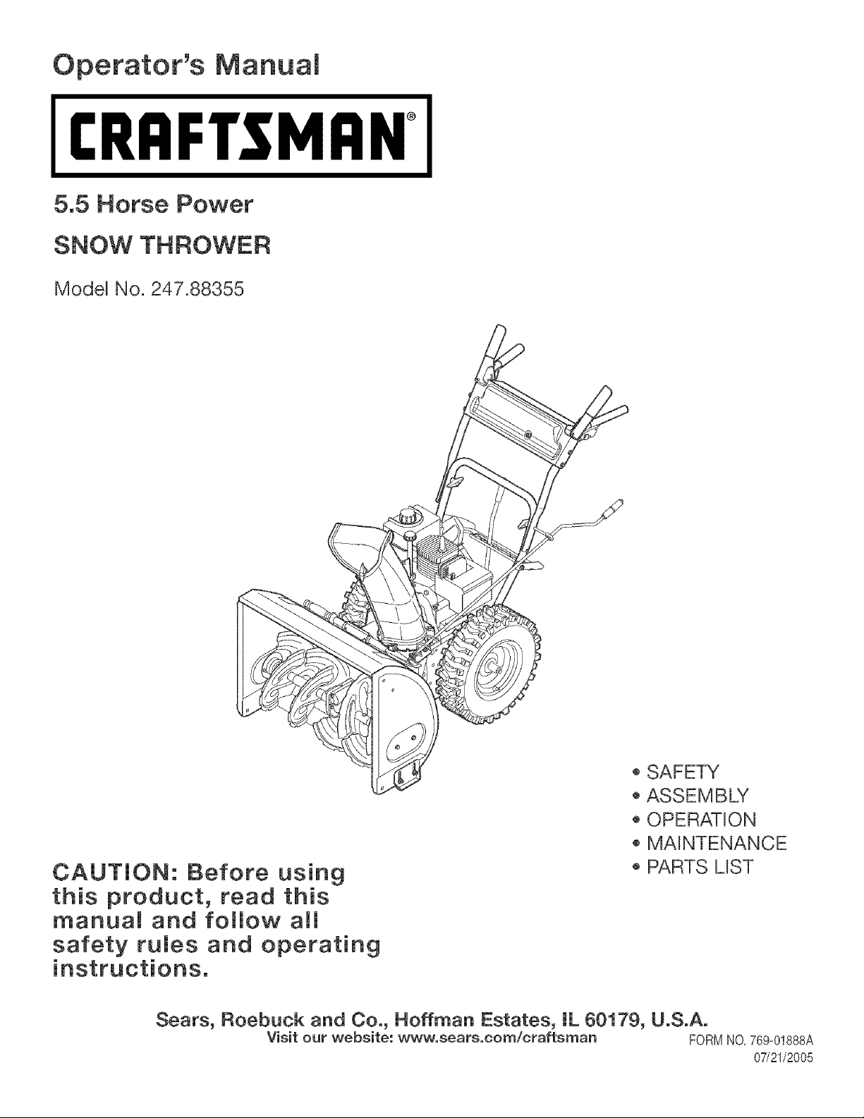
5.5 Horse Power
SNOW THROWER
Model No. 247.88355
CAUTION: Before using
this product, read this
manual and follow a[[
safety rules and operating
_,SAFEW
_,ASSEMBLY
o OPERATION
o MAINTENANCE
o PARTS MST
Sears, Roebuck and Co., Hoffman Estates, [L 60179, U.S.A.
Visit our website: www, sears,com/craftsman FORMNO,769=01888A
07/21/2005
WarrantyStatement..................................Page2
RepairProtectionAgreement....................Page2
SafeOperationPractices..........................Pages3-5
Assembly...................................................Pages6-7
Starting/Stoppinginstructions..................Pages10-11
Operation...................................................Pages8-12
Two-YearWarrantyonCraftsmanSnowThrower
Fortwoyearsfromthedateofpurchase,whenthisCraftsmanSnowThrowerismaintained,lubricatedandtunedupaccordingtotheinstructions
intheowner'smanual,Searswillrepair,freeofcharge,anydefectinmaterialandworkmanship,IfthisCraftsmansnowthrowerisusedfor
commercialorrentalpurposes,thiswarrantyapplbsforonly30daysfromthedateofpurchase,
Thiswarrantydoesnotcover:
Expendabbitemswhichbecomewornduringnormaluse,suchasskidshoes,shaveplateandsparkplugs,
Repairsnecessarybecauseofoperatorabuseornegligence,includingbentcrankshaftsandthefailuretomaintaintheequipmentaccording
totheinstructionscontainedintheowner'smanual
WARRANTYSERVICEiSAVAILABLEBYRETURNINGTHECRAFTSMANSNOWTHROWERTOTHENEAREST
SEARSPARTS&REPAIRCENTERINTHEUNITEDSTATES,
ThiswarrantyapplbsonlywhilethisproductisinuseintheUnitedStates,
TOLOCATETHENEARESTSEARSPARTS&REPAIRCENTERORTOSCHEDULESERVICE,
SIMPLYCONTACTSEARSAT1-800-4-MY-HOME@,
Thiswarrantygivesyouspecificlegalrightsandyoumayabehaveotherrightswhichmayvaryfromstatetostate,
SEARS,ROEBUCKANDCO.,D/817WA,HOFFMANESTATES,IL60179
Repair Protection Agreements
Congratula%nson makinga smart purchase,YournewCraftsman@
productis designedand manufacturedfor yearsof dependabb opera=
tion,But likeallproducts,it mayrequirerepairfromtimeto time,That's
whenhavinga RepairProtectionAgreementcansaveyoumoneyand
aggravation,
Here'swhat'sincludedin the Agreement:
Expertserviceby our 12,000professionalrepairspecialists
Unlimitedserviceand nochargefor partsand laboronall covered
repairs
Productreplacementif yourcoveredproductcan'tbe fixed
Discountof 10%fromregularpriceof serviceand service-related
partsnotcoveredby theagreement;also,10%off regularpriceof
preventivemaintenancecheck
Fasthelp by phone- phonesupportfroma Searstechnicianon
productsrequiringin-homerepair,plus convenientrepair
scheduling
PurchaseaRepairProtectionAgreementnowandprotectyourself
fromunexpectedhassleand expense,
Once youpurchasethe Agreement,a simplephonecall is all thatit
takesfor youto scheduleservice,Youcan call anytimeday ornight,or
sehedub a serviceappointmentonline,
Searshasover12,000professionalrepairspecialists,who have
accessto over4,5millionquality partsand accessories,That'sthe
kindof
professionalismyou cancount on to helpprolongthe life of yournew
purchaseforyears to come,PurchaseyourRepairProtectionAgree-
menttoday!
Some limitations and exclusions apply. For prices and additional
informationcall 1-800-827-6655.
Sears Installation Service
ForSearsprofessionalinstallationof homeappliances,garagedoor
openers,waterheaters,andother majorhomeitems,in the U.S.A.call
1=800=4=MY=HOME@
Horse Power: 5,5
Engine Oil: SAE 5W-30
Fuel: Unleaded Gasoline
Spark Hug:
Engine: Tecumseh LH195SP
Model Number .............................................................
Serial Number ..............................................................
Date of Purchase ..........................................................
Record the model number, serial number
and date of purchase above
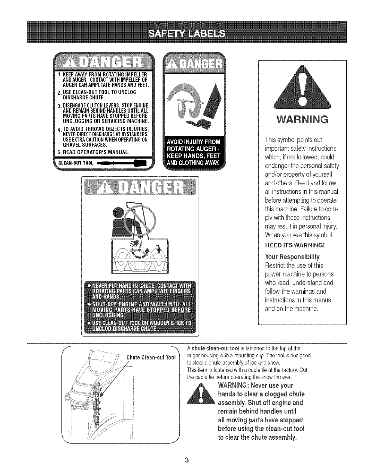
1.KEEPAWAYFROMROTATINGIMPELLER
ANDAUGER.CONTACTWITHIMPELLEROR
AUGERCANAMPUTATEHANDSANDFEET,
2. USECLEAN-OUTTOOLTOUNCLOG
DISCHARGECHUTE.
3. DISENGAGECLUTCHLEVERS,STOPENGINE,
ANDREMAINBEHINDHANDLESUNTILALL
MOVINGPARTSHAVESTOPPEDBEFORE
UNCLOGGINGORSERVICINGMACHINE,
4. TO AVOIDTHROWNOBJECTSINJURIES,
NEVERDIRECTDISCHARGEATBYSTANDERS.
USEEXTRACAUTIONWHENOPERATINGON
GRAVELSURFACES.
5. READOPERATOR'SMANUAL.
This symbol points out
importantsafety instructions
which, if not followed,could
endangerthe personal safety
and/or propertyof yourself
and others. Readand follow
all instructionsin this manual
beforeattemptingto operate
this machine.Failureto com-
plywith these instructions
mayresult in personalinjury.
When you see this symbol.
HEED ITS WARNING!
Your Responsibility
Restrictthe use of this
power machine to persons
who read, understandand
follow the warnings and
instructions in this manual
and on the machine.
A chute cleamout tool is fastenedto the top of the
augerhousingwitha mountingclip, The tool is designed
to cleara chuteassemblyof ice and snow,
Thisitemis fastenedwith a cable tie at the factory,Cut
the cabletie beforeoperatingthe snowthrower,
,_ WARNING:Never use your
hands to clear a clogged chute
assembly. Shut off engine and
remain behind handles until
all moving parts have stopped
before using the clean-out tool
to clear the chute assembly.
3
WARNING:EngineExhaust,someofitsconstituents,andcertainvehiclecomponentscontainoremit
chemicalsknowntoStateofCaliforniatocausecancerandbirthdefectsorotherreproductiveharm.
DANGER:ThismachinewasbuilttobeoperatedaccordingtotherulesforsafeoperationinthismanualAswithanytype
ofpowerequipment,carelessnessorerroronthepartoftheoperatorcanresultinseriousinjury.Thismachineis capable
ofamputatinghandsandfeetandthrowingobjects.Failuretoobservethefollowingsafetyinstructionscouldresultin
seriousinjuryordeath.
WARNING:Thissymbolpointsoutimportantsafetyinstructionswhich,ifnotfollowed,couldendangerthe
personalsafetyand/orpropertyofyourselfandothers.Readandfollowallinstructionsinthismanualbefore
attemptingtooperatethismachine.Failuretocomplywiththeseinstructionsmayresultin personalinjury.
WhenyouseethissymbolHEEDITSWARNING!
YourResponsibility:Restricttheuseofthispowermachinetopersonswhoread,understandandfollowthewarnings
andinstructionsin thismanualandonthemachine.
Preparation
1. Thoroughlyinspectthe areawherethe equipmentisto be used. Remove
all doormats,newspapers,sleds,boards,wiresand otherforeignobjects,
whichcould betrippedoveror thrown bythe auger/impeller.
2. Alwayswearsafetyglassesor eyeshields duringoperationandwhile
performingan adjustmentor repairto protectyoureyes.Thrownobjects
which ricochetcan causeserious injury to the eyes.
3. Donot operatewithoutwearingadequatewinteroutergarments.Donot
wearjewelry,longscarvesor otherlooseclothing,whichcouldbecome
entangledin moving parts.Wear footwearwhichwill improvefootingon
slippery surfaces.
4. Usea groundedthree-wireextensioncord and receptaclefor all unitswith
electricstart engines.
5. Adjustcollector housingheightto clear gravelor crushedrocksurfaces.
6. Disengageall controlleversbeforestartingthe engine.
7. Neverattemptto make anyadjustmentswhileengineis running,except
where specificallyrecommendedinthe operator'smanual.
8. Letengineand machineadjustto outdoortemperaturebefore startingto
clear snow.
9. To avoidpersonalinjuryor propertydamageuse extremecare in handling
gasoline.Gasolineis extremelyflammableandthe vaporsareexplosive.
Seriouspersonalinjury can occurwhen gasolineis spilled on yourself
or yourclothes,which can ignite.Washyourskin andchangeclothes
immediately.
a. Useonlyan approvedgasolinecontainer.
b. Extinguishall cigarettes,cigars,pipesand othersourcesof ignition.
c. Neverfuelmachine indoors.
d. Neverremovegas cap or addfuel whilethe engine is hot or running.
e. Allowengine to cool at least two minutesbefore refueling.
f. Neveroverfill fuel tank. Filltank to no morethan _J2inch belowbottom
of filler neckto providespacefor fuel expansion.
g. Replacegasolinecap andtighten securely.
h. If gasolineis spilled, wipeit offthe engine andequipment.Move
machineto anotherarea. Wait5 minutesbeforestartingthe engine.
Neverstore themachineorfuel container insidewherethere is an open
flame, sparkor pilot light (e.g.furnace,water heater,space heater,
clothesdryeretc.).
Allowmachineto cool at least 5 minutes beforestoring.
Training
1 Read,understand,andfollowall instructionson the machineand inthe
manual(s)beforeattemptingto assembleandoperate.Keepthis manualin
a safe placeforfuture andregularreferenceandfor orderingreplacement
parts.
2. Be familiarwith all controlsandtheir properoperation.Knowhowto stop
themachineand disengagethem quickly.
3. Neverallowchildrenunder14 yearsoldto operatethis machine.Ohildren
14 yearsold andovershouldread andunderstandthe operationinstruc-
tionsand safetyrulesinthis manualandshouldbe trainedandsupervised
bya parent.
4. Neverallowadultsto operatethis machinewithoutproperinstruction.
5. Thrownobjectscan causeserious personalinjury'.Planyoursnow-throwing
patternto avoiddischargeof materialtoward roads,bystandersandthe like.
6. Keepbystanders,helpers,pets andchildrenat least 75 feetfrom the
machinewhileit is in operation.Stopmachineif anyoneentersthe area.
7. Exercisecautionto avoidslippingor falling,especiallywhenoperatingin
reverse.
4
Operation
1. Do not put hands or feet near rotatingparts, inthe auger/impellerhousing
orchute assembly.Contactwith the rotating partscan amputatehands
andfeet.
2. The auger/impellercontrolleveris a safetydevice.Neverbypassits
operation.Doingso makesthe machineunsafeand maycause personal
injury.
3. The control leversmust operateeasilyin both directionsand automatically
returnto the disengagedpositionwhenreleased.
4. Neveroperatewitha missingor damagedchute assembly.Keepall safety
devicesin placeand working.
5. Neverrunan engine indoorsor in a poorlyventilatedarea. Engineexhaust
containscarbonmonoxide,an odorlessanddeadlygas.
6. Do not operatemachinewhile underthe influenceof alcoholor drugs.
7. Mufflerand enginebecomehot and can causea burn. Donot touch.
8. Exerciseextremecautionwhen operatingon orcrossinggravel surfaces.
Stay alert forhidden hazardsortraffic,
9. Exercisecautionwhenchangingdirectionandwhile operatingon slopes.
10.Plan yoursnow-throwingpatternto avoiddischargetowards windows,
walls, carsetc.Thus, avoidingpossiblepropertydamageor personal
injurycausedby a ricochet.
11.Neverdirectdischargeat children,bystandersand petsor allowanyonein
front of the machine.
12.Do notoverloadmachinecapacityby attemptingto clearsnow at toofast
of a rate.
13.Neveroperatethis machinewithoutgood visibilityor light. Alwaysbe sure
of yourfooting and keepa firm holdon the handles.Walk, never run.
14.Disengagepowerto the auger/impellerwhen transportingor notin use.
15.Neveroperatemachineat hightransport speedson slipperysurfaces.
Lookdownand behindand use carewhenbackingup.
16.If the machineshouldstart to vibrate abnormally,stop the engine,
disconnectthespark plugwire andground it againsttheengine.Inspect
thoroughlyfor damage.Repairany damagebeforestartingand operating.
17.Disengageall controlleversandstop enginebeforeyou leavethe operat-
ing position(behindthe handles).Wait until the auger/impellercomes
to a completestopbeforeuncloggingthechute assembly,makingany
adjustments,or inspections.
18.Neverput your hand inthe dischargeor collectoropenings.Alwaysuse
theclean-outtool providedto unclogthe dischargeopening.Do not unclog
chuteassemblywhileengine is running.Shutoff engineand remain
behindhandlesuntil allmoving partshavestoppedbeforeunclogging.
19.Use only attachmentsand accessoriesapprovedbythe manufacturer(e.g.
wheelweights,tire chains,cabs etc.).
20.If situationsoccurwhich are not coveredin this manual,use careand
goodjudgment. ContactyourSears ServiceCenterfor assistance.
Maintenance & Storage
1. Nevertamperwith safetydevices.Check their properoperationregularly.
Referto the maintenanceand adjustmentsectionsof this manual.
2. Beforecleaning,repairing,or inspectingmachinedisengageallcontrol
leversand stoptheengine.Wait until the auger/impellercometo a
completestop.Disconnectthe spark plugwire and groundagainstthe
engineto preventunintendedstarting.
3. Check bolts andscrewsfor propertightnessat frequentintervalsto keep
the machinein safe workingcondition.Also, visuallyinspectmachinefor
any damage.
4. Donot changethe enginegovernorsettingor over-speedthe engine.The
governorcontrolsthe maximumsafeoperatingspeedof the engine.
5. Snowthrowershaveplatesandskid shoesaresubjectto wear and
damage.Foryour safetyprotection,frequentlycheck all componentsand
replacewithoriginal equipmentmanufacturer's(OEM)parts only."Use of
parts which do not meet the originalequipmentspecificationsmay leadto
improperperformanceand compromisesafety!"
6. Checkcontrols periodicallyto verify they engageanddisengageproperly
and adjust,if necessary.Referto the adjustmentsectionin this operator's
manualfor instructions.
7. Maintainor replacesafetyand instructionlabels, as necessary.
8. Observeproper disposallawsand regulationsfor gas, oil,etc. to protect
the environment.
9. Priorto storing,run machinea few minutesto clear snowfrom machine
and preventfreezeup of auger/impeller.
10.Neverstorethe machineor fuel containerinside wherethere is an open
flame, sparkor pilot light suchas a water heater,furnace,clothes dryer
etc.
11.Alwaysreferto the operator'smanualfor properinstructionson off-season
storage.
Do not modify engine
Toavoidseriousinjury'or death,do notmodifyenginein anyway.Tampering
withthe governorsettingcan leadto a runaway'engineandcauseit to operate
at unsafespeeds.Nevertamperwithfactorysettingof engine governor.
Notice regarding Emissions
Engineswhichare certifiedto complywith CaliforniaandfederalEPAemission
regulationsfor SORE(SmallOff RoadEquipment)are certifiedto operateon
regularunleadedgasoline,and may'includethe followingemissioncontrolsys-
tems:EngineModification(EM)andThreeWayCatalyst(TWC)if so equipped.
Engine identification Decal
Thisdecal indicatestheengine'smodelnumber,specificationandthe dateof
manufacture.Pleaselook atthe decal on the engine ofyour equipmentand
recordthese informationforfuturereference.
The engineidentificationdecalalso includesenginelifespecificationsfor the
emissions-relatedusefullifeperiodof the engine.This periodrelatesto the
emissioncompliancelifeas certifiedby EPAand/orCARB.Tofind the life period
specificationof the engine,pleasereadthe enginedecaland locatethe letter
(enclosedbyquotationmarks)betweenthewordsModerateand LifePeriod.
Matchone of the followingletterswiththeletter printedon yourdecal.For
example,HMSK80 modelsare designatedas:
"C"-- 250hours
"B"-- 500 hours
"A"-- 1000hours
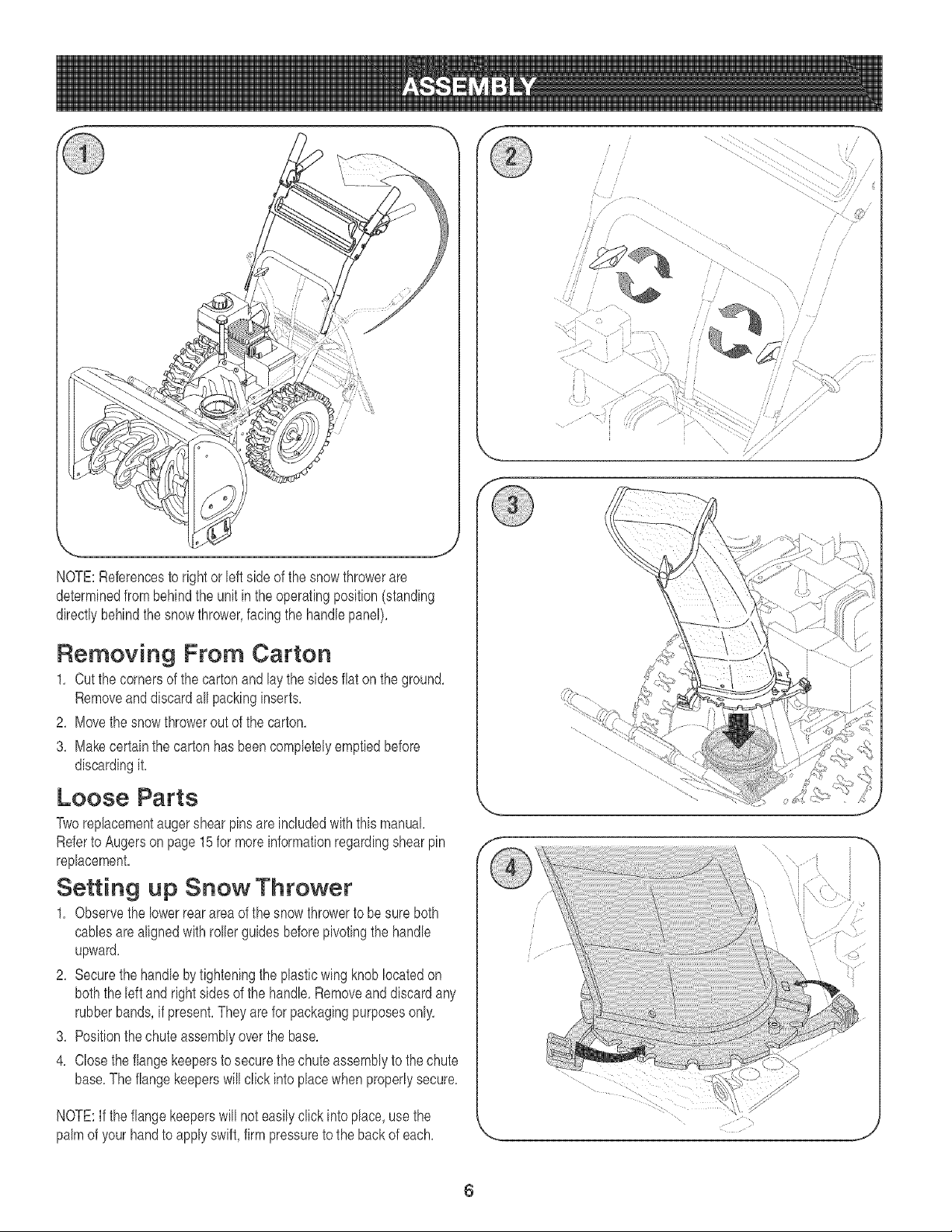
NOTE:Referencesto rightor bft side of the snowthrowerare
determinedfrombehindthe unit inthe operatingposition(standing
directlybehindthesnowthrower,facing the handlepanel),
Removing From Carton
1, Cut the cornersof the cartonandlay the sidesflaton the ground,
Removeand discardallpackinginserts,
2, Movethe snowthrowerout of the carton,
3, Makecertainthe cartonhas beencompletelyemptiedbefore
discardingit,
Loose Parts
Tworeplacementaugershearpinsare includedwith this manual,
Referto Augersonpage15for moreinformationregardingshearpin
replacement,
Setting up Snow Thrower
1, Observethe lowerrearareaof thesnowthrowerto besure both
cablesarealignedwith rollerguidesbeforepivotingthe handle
upward,
2, Securethe handleby tighteningthe plasticwing knoblocatedon
boththe leftand rightsides of the handb, Removeanddiscardany
rubberbands,if present,They are for packagingpurposesonly,
8, Positionthechuteassemblyoverthe base,
4, Closethe flangekeepersto securethe chute assernblyto the chute
base,The flangekeeperswill click intoplacewhenproperlysecure,
NOTE:If the flangekeeperswill not easilyclick into place,usethe
palmof your handto applyswift,firm pressureto the backof each,
6
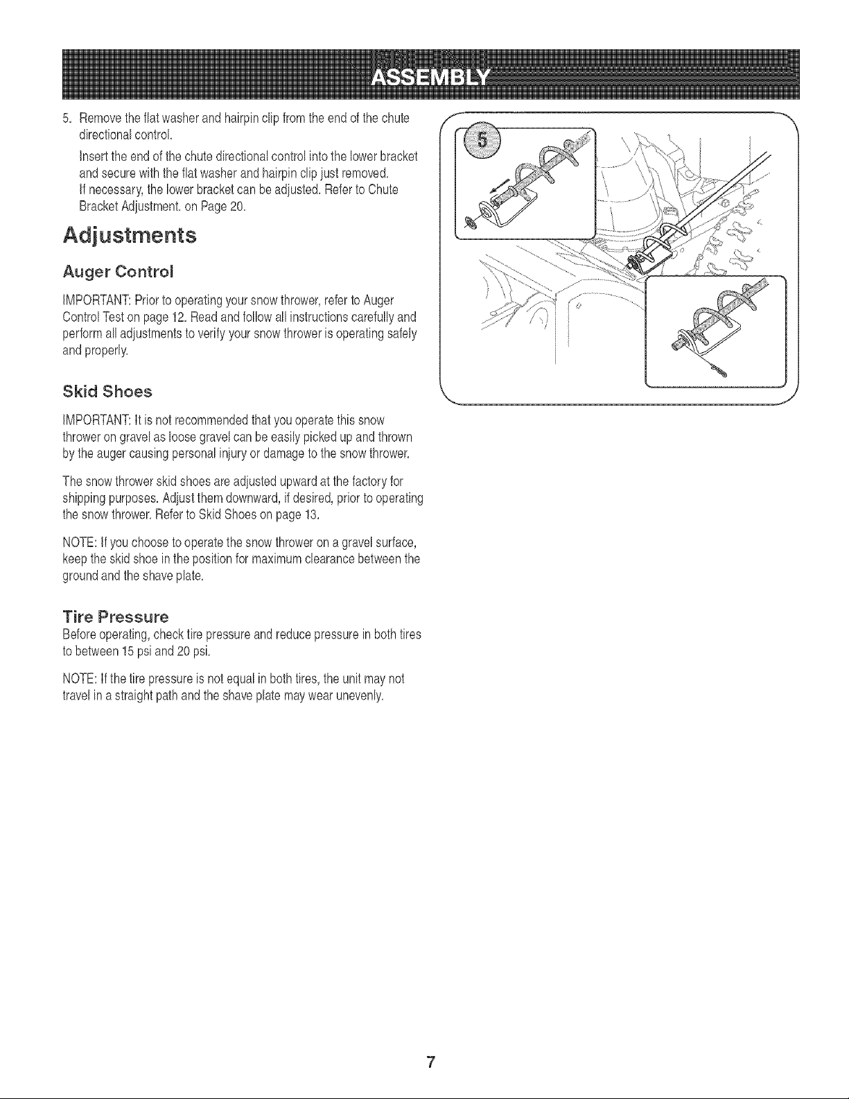
directionalcontrol
5, Removetheflatwasherand hairpinclip from the endof the chute
insertthe end of the chutedirectionalcontrolintothe lowerbracket
andsecurewiththe flat washerandhairpinclipiust removed,
if necessary',the lowerbracketcan beadiusted,Referto Chute
BracketAdiustment,on Page20,
Adjustments
Auger Contro_
iMPORTANT:Priorto operatingyoursnowthrower,referto Auger
ControlTeston page12,Readandfollowall instructionscarefullyand
performalladiustmentsto verify yoursnowthroweris operatingsafely
andproperly,
Skid Shoes
iMPORTANT:It is not recommendedthatyouoperatethis snow
throweron gravelas loosegravelcan beeasilypickedupandthrown
by theaugercausingpersonaliniuryor damageto the snowthrower,
The snow throwerskid shoes are adiustedupwardat the factoryfor
shippingpurposes,Adiustthemdownward,if desired,priorto operating
the snowthrower,Referto Skid Shoeson page 13,
NOTE:if you chooseto operatethe snowthrowerona gravelsurface,
keepthe skidshoein the positionfor maximumclearancebetweenthe
groundandthe shaveplate,
Tire Pressure
Beforeoperating,checktire pressureandreducepressurein bothtires
to between15 psiand20 psi,
NOTE:If the tire pressureis notequalinboth tires,the unitmaynot
travelin astraightpathandthe shaveplate maywearunevenly,
7
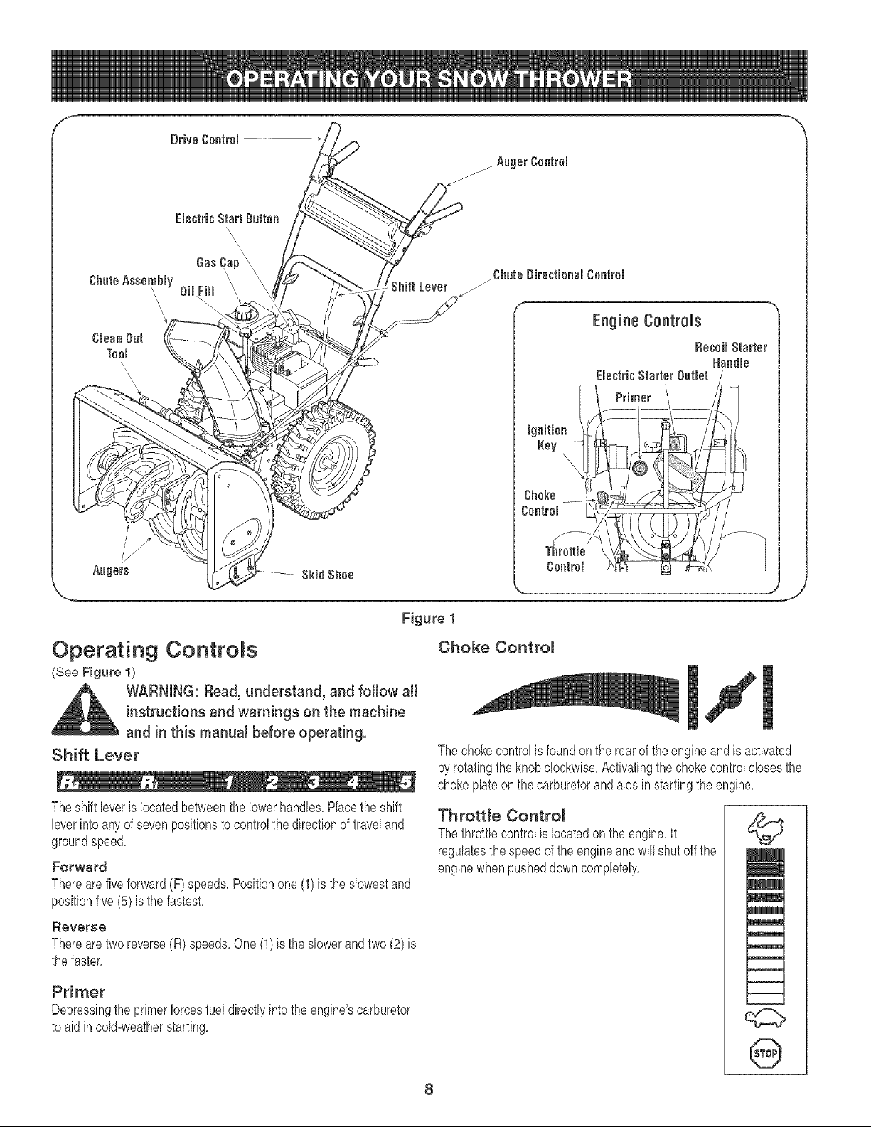
Figure 1
Operating Controls
(See Figure 1)
WARNING: Read, understand, and follow all
instructions and warnings on the machine
and in this manual before operating.
Shift Lever
Theshift leveris locatedbetweenthe lowerhandles,Placetheshift
leverintoany of sevenpositionsto controlthe directionof traveland
groundspeed,
Forward
Thereare five forward(F) speeds,Positionone(1)is the slowestand
positionfive(5) is the fastest,
Reverse
Thereare two reverse(R) speeds,One(1)is the slowerandtwo (2)is
the faster,
Primer
Depressingthe primerforcesfuel directlyintothe engine'scarburetor
to aid in cold=weatherstarting,
Choke Contro_
The chokecontrolis foundon the rearof theengine and is activated
byrotatingthe knobclockwise,Activatingthechokecontrolclosesthe
chokeplateon the carburetorandaids instartingthe engine,
Throttle Control
The throttlecontrolis locatedonthe engine,It
regulatesthe speedof the engineandwill shut offthe
enginewhen pusheddowncompletely,
©
m
l
m
8
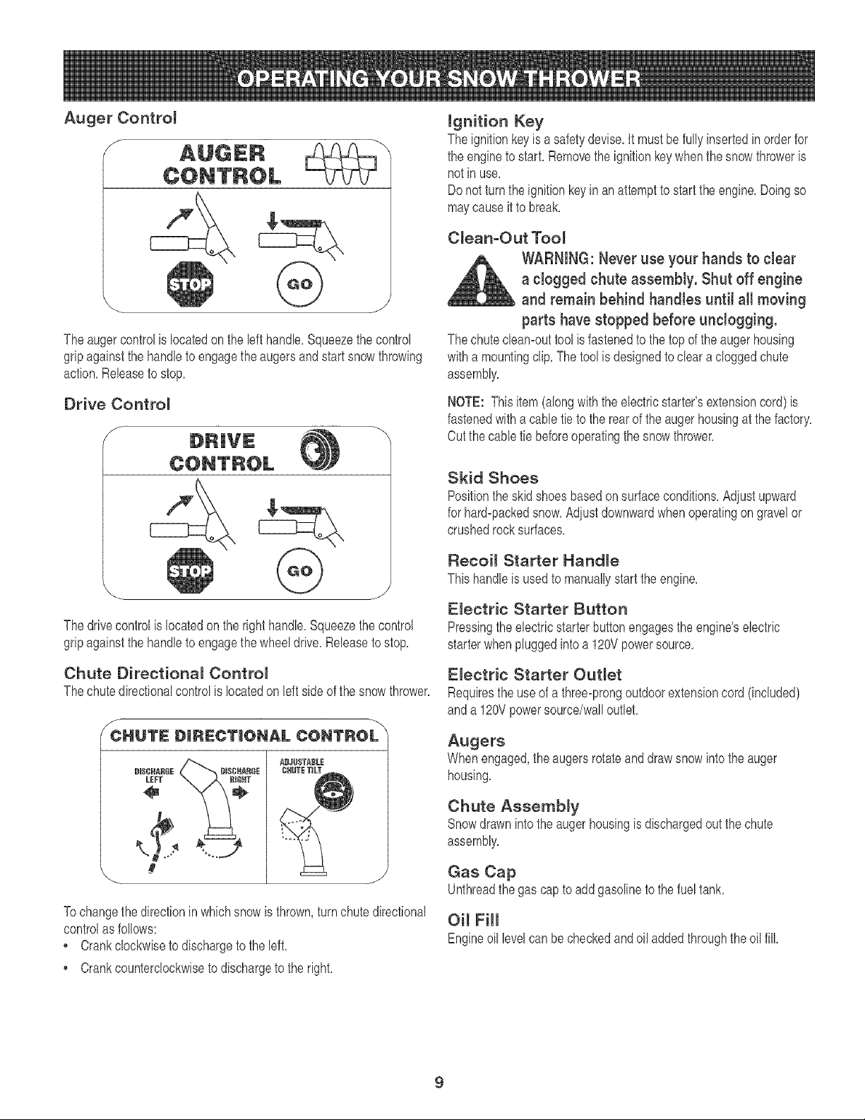
The auger controlis locatedonthe lefthandle,Squeezethe control
gripagainstthe handleto engagethe augersandstart snowthrowing
action,Releaseto stop,
Drive Control
f
--x
ignition Key
The ignitionkeyis asafetydevise,It mustbe fully insertedinorderfor
the engineto start, Removethe ignitionkeywhenthe snow throweris
notin use,
Donot turnthe ignitionkey in an attemptto startthe engine,Doingso
maycauseit to break,
C_ean-Out Tool
WARNING: Never use your hands to cJear
a clogged chute assembly. Shut off engine
and remain behind handles untit aHmoving
parts have stopped before unclogging.
The chutecleamouttool is fastenedto the top ofthe augerhousing
witha mountingclip,The tool is designedto cleara cloggedchute
assembly,
NOTE: Thisitem(alongwiththe electricstarter'sextensioncord) is
fastenedwith a cabletie to the rearof the auger housingat the factory,
Cutthe cabletie beforeoperatingthe snowthrower,
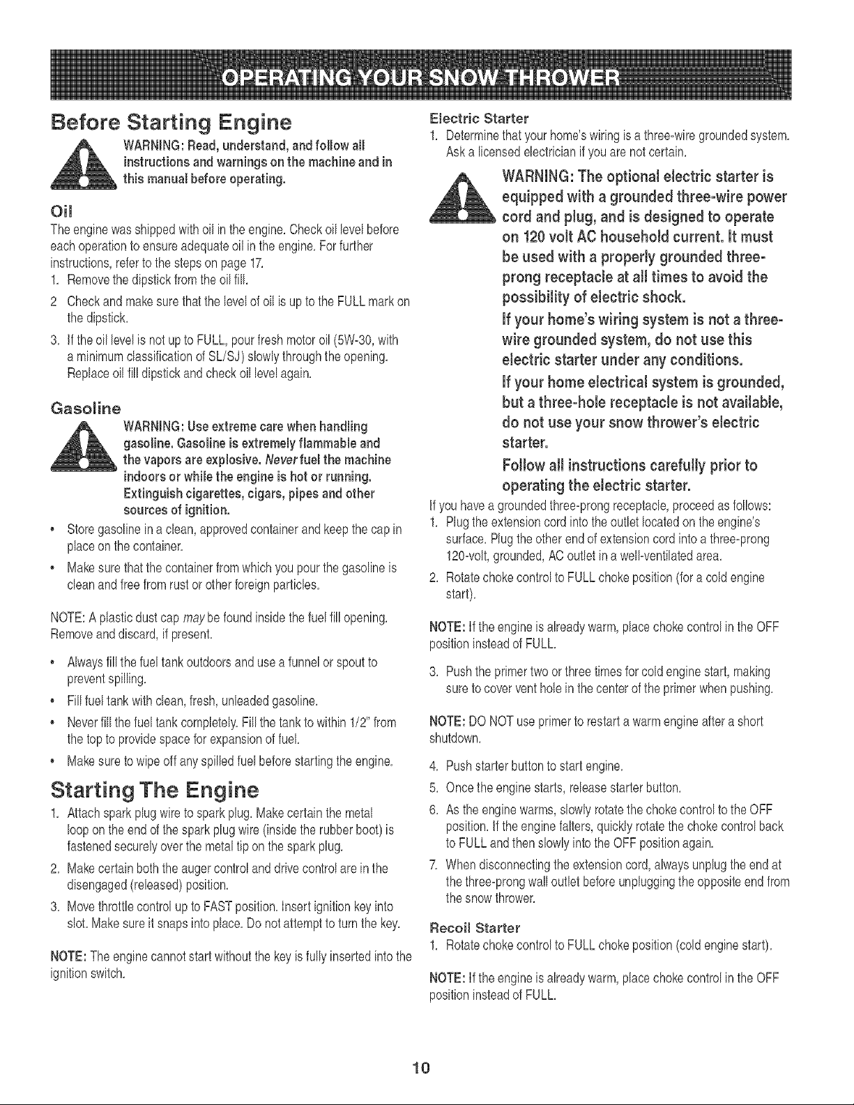
The drivecontrolis locatedon the right handle,Squeezethecontrol
gripagainstthe handleto engagethe wheeldrive,Releaseto stop,
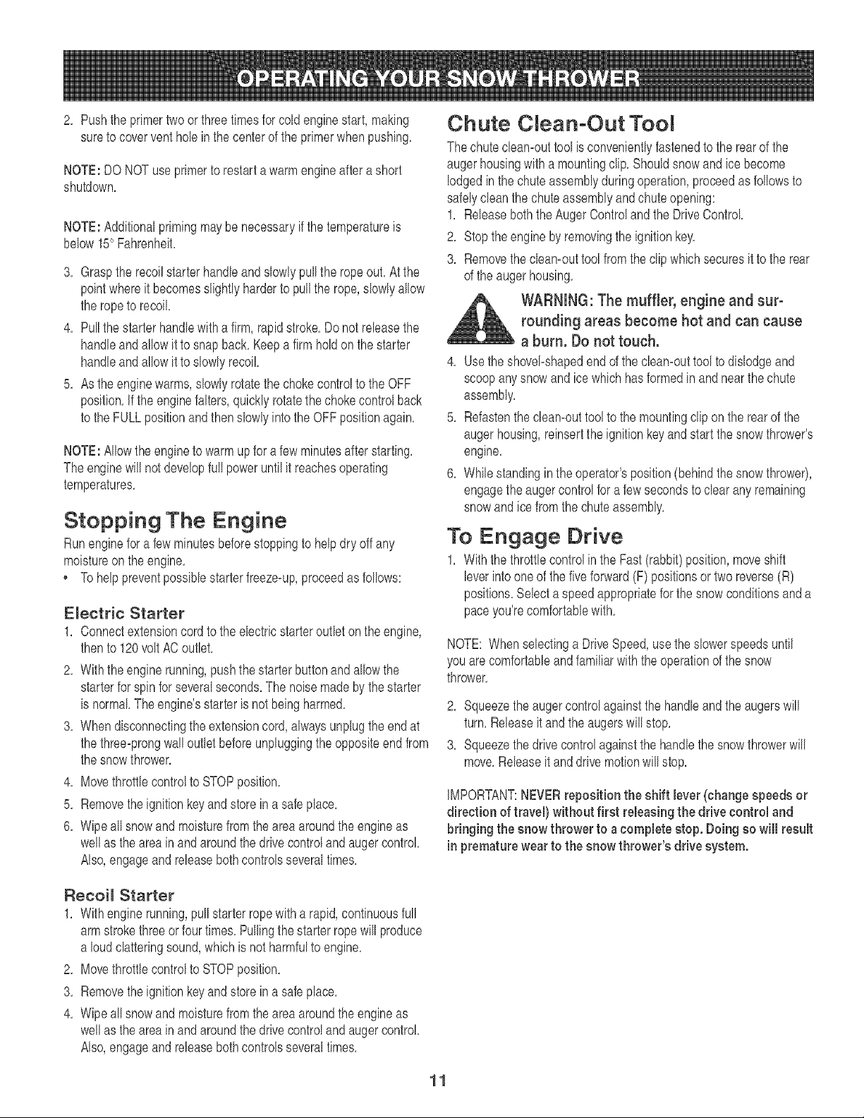
Chute Directiona_ ControJ
The chute directionalcontrolis locatedon left side of the snowthrower,
CHUTe: D_R_:CT|ONAL CONTROL
\
BI$CHARGE
LEFT
S
To changethe directionin whichsnowis thrown,turn chutedirectional
controlas follows:
• Crankclockwiseto dischargeto the left,
, Crankcounterclockwiseto dischargeto the right,
Skid Shoes
Positionthe skid shoes basedonsurfaceconditions,Adiustupward
for hard-packedsnow,Adiustdownwardwhenoperatingongravelor
crushedrocksurfaces,
Recoil Starter HandJe
Thishandleis usedto manuallystart the engine,
EJectric Starter Button
Pressingtheelectricstarterbuttonengagesthe engine'selectric
starterwhenpluggedinto a 120Vpowersource,
E_ectric Starter Out_et
Requiresthe useof a three-prongoutdoorextensioncord (included)
anda 120Vpowersource/walloutlet,
Augers
Whenengaged,the augersrotateanddrawsnowinto the auger
housing,
Chute Assembly
Snowdrawnintothe augerhousingis dischargedout the chute
assembly,
Gas Cap
Unthreadthe gas cap to addgasolineto the fueltank,
Oi_ FiH
Engineoil levelcan becheckedandoil addedthroughthe oil fill
9
Before Starting Engine
WARNING:Read,understand, and follow all
instructionsand warnings on the machine and in
this manual beforeoperating.
Oil
Theengine wasshippedwithoil inthe engine,Checkoil levelbefore
eachoperationto ensureadequateoil inthe engine,Forfurther
instructions,referto thestepson page17,
1, Removethe dipstickfrom the oilfill,
2 Checkand makesurethatthe levelof oil is upto the FULLmarkon
the dipstick,
3, If theoil levelis notupto FULL,pourfresh motoroil (5%30, with
a minimumclassificationof %/%) slowlythroughthe opening,
Replaceoil fill dipstickandcheckoil levelagain,
Gasoline
WARNING:Use extreme cars when handling
gasoline. Gasoline is extremely flammable and
the vapors are explosive. Neverfusl the machine
indoorsor while the engine is hot or running.
Extinguish cigarettes, cigars, pipes and other
sources of ignition.
• Storegasolinein aclean,approvedcontainerand keepthe capin
placeon the container,
, Makesurethat the containerfromwhichyou pourthe gasolineis
cleanand freefromrustor otherforeignparticles,
NOTE:A plasticdust cap maybe foundinsidethefuel fill opening,
Removeanddiscard,if present,
Alwaysfill the fueltankoutdoorsandusea funnelor spoutto
preventspilling,
• Fill fueltankwithclean,fresh, unleadedgasoline,
• Neverfill the fueltank completely,Fill the tankto within 1/2"from
the topto providespacefor expansionof fuel
• Makesureto wipe off anyspilledfuel beforestartingtheengine,
Starting "['he Engine
1, Attachsparkplugwireto sparkplug, Makecertainthe metal
looponthe end of the sparkplug wire(insidethe rubberboot)is
fastenedsecurelyoverthe metaltip on thesparkplug,
2, Makecertain boththe augercontrolanddrivecontrolare inthe
disengaged(released)position,
3, Movethrottlecontrolup to FASTposition,Insertignitionkeyinto
slot,Make sureit snaps intoplace,Do notattemptto turnthe key,
NOTE:The enginecannotstart withoutthe key is fullyinsertedintothe
ignitionswitch,
Electric Starter
1, Determinethat yourhome'swiringis a three-wiregroundedsystem,
Aska licensedelectricianif you are not certain,
WARNING: The optional electric starter is
equipped with a grounded three-wire power
cord and plug, and is designed to operate
on 120volt AC household current. It must
be used with a properly grounded three-
prong receptacle at all times to avoid the
possibility of electric shock.
If your home's wiring system is not a three-
wire grounded system, do not use this
electric starter under any conditions.
If your home electrical system is grounded,
but a three-hole receptacle is not available,
do not use your snow thrower's electric
starter.
Follow all instructions carefully prior to
operating the electric starter.
if you havea groundedthree-prongreceptacle,proceedas follows:
1, Plug the extensioncord intothe outletlocatedonthe engine's
surface,Plugtheother endof extensioncord intoa three-prong
120-volt,grounded,ACoutletina well-ventilatedarea,
2, Rotatechokecontrolto FULL chokeposition(for a coldengine
start),
NOTE:If theengine is alreadywarm,placechokecontrolin the OFF
positioninsteadof FULL,
3, Pushthe primertwoorthree timesforcold enginestart,making
sure to coverventholeinthe centerof the primerwhenpushing,
NOTE:DO NOTuse primerto restarta warmengine aftera short
shutdown,
4, Pushstarterbuttonto startengine,
5, Oncethe engine starts,releasestarterbutton,
6, As the enginewarms,slowlyrotatethe chokecontrolto the OFF
position,If theenginefalters,quicklyrotatethe chokecontrolback
to FULLandthenslowlyintothe OFFpositionagain,
7, Whendisconnectingthe extensioncord, alwaysunplugthe endat
the three-prongwall outletbeforeunpluggingtheoppositeend from
the snow thrower,
Recoil Starter
1, Rotatechokecontrolto FULL chokeposition(coldenginestart),
NOTE:If theengine is alreadywarm,placechokecontrolin the OFF
positioninsteadof FULL,
10
2, Pushthe primertwo or threetimesfor cold enginestart, making
sureto coverventholein the centerof the primerwhenpushing,
NOTE: DONOTuseprimerto restartawarmengineaftera short
shutdown,
NOTE:Additionalprimingmaybe necessaryif the temperatureis
below15° Fahrenheit,
3, Graspthe recoilstarterhandleand slowlypull the ropeout,At the
pointwhereit becomesslightlyharderto pull the rope,slowlyallow
the ropeto recoil
4, Pull thestarter handlewith a firm, rapidstroke,Donot releasethe
handleandallowit to snapback,Keepa firm holdon thestarter
handleandallowit to slowlyrecoil
5, As theengine warms,slowlyrotatethe chokecontrolto the OFF
position,If the enginefalters,quicklyrotatethe chokecontrolback
to the FULLpositionandthenslowlyinto the OFFpositionagain,
NOTE:Allowthe engineto warmupfor a few minutesafter starting,
The enginewill notdevelopfull poweruntilit reachesoperating
temperatures,
Stopping The Engine
Runenginefor a fewminutesbeforestoppingto helpdry off any
moistureon the engine,
. Tohelppreventpossiblestarterfreeze-up,proceedas follows:
E_ectric Starter
1, Connectextensioncordto the electricstarteroutleton theengine,
thento 120volt AC outlet,
2, With theenginerunning,pushthe starterbuttonandallowthe
starterfor spinfor severalseconds,The noisemadebythe starter
is normal Theengine'sstarteris not being harmed,
3, Whendisconnectingthe extensioncord,alwaysunplugthe endat
the three-prongwalloutlet beforeunpluggingthe oppositeendfrom
the snowthrower,
4, Movethrottlecontrolto STOPposition,
5, Removetheignitionkey and store in a safe place,
6, Wipeallsnowandmoisturefrom theareaaroundthe engineas
wellas the area in and aroundthe drivecontroland augercontrol
Also,engageand releasebothcontrolsseveraltimes,
Chute C ean-Out TooR
The chutecleamouttool is convenientlyfastenedto the rearof the
augerhousingwith a mountingclip,Shouldsnowand ice become
lodgedinthe chute assemblyduringoperation,proceedasfollowsto
safelycleanthe chuteassemblyandchuteopening:
1, Releaseboththe AugerControlandthe DriveControl
2, Stoptheengine by removingthe ignitionkey,
3, Removethe cleamouttool fromthe clipwhichsecuresit to the rear
of the augerhousing,
WARNING: The muffler, engine and sur-
rounding areas become hot and can cause
a burn. Do not touch.
4, Usethe shovel-shapedend of the cleamouttoolto dislodgeand
scoopanysnow and ice whichhas formedin and nearthe chute
assembly,
5, Refastenthecleamouttoolto the mountingclipon the rearof the
augerhousing,reinsertthe ignitionkeyand startthe snowthrower's
engine,
6, Whilestandinginthe operator'sposition(behindthe snowthrower),
engagethe augercontrolfora fewsecondsto clear anyremaining
snowandice from thechuteassembly,
To Engage Drive
1, With the throttlecontrolin the Fast(rabbit)position,moveshift
leverintooneof the fiveforward(F) positionsor two reverse(R)
positions,Selecta speedappropriatefor the snowconditionsanda
paceyou'recomfortablewith,
NOTE: Whenselectinga DriveSpeed,usethe slowerspeedsuntil
you are comfortableand familiarwith theoperationof the snow
thrower,
2, Squeezethe augercontrolagainstthe handleandthe augerswill
turn,Releaseit and the augerswill stop,
3, Squeezethe drivecontrolagainstthe handlethe snowthrowerwill
move,Releaseit and drh,'emotionwill stop,
IMPORTANT:NEVERreposition the shift lever (change speeds or
direction of travel) without first releasing the drive control and
bringing the snow thrower to a complete stop. Doing so will result
in premature wear to the snow thrower's drive system.
Reeoi_ Starter
1, With enginerunning,pull starterropewitha rapid,continuousfull
armstrokethreeor fourtimes, Pullingthe starterrope will produce
a loudclatteringsound,whichis notharmfulto engine,
2, Movethrottlecontrolto STOPposition,
3, Removetheignitionkey and store in a safe place,
4, Wipeallsnowandmoisturefrom theareaaroundthe engineas
wellas the area in and aroundthe drivecontroland augercontrol
Also,engageand releasebothcontrolsseveraltimes,
11
To Engage Augers
1, Toengagethe augersandstart throwingsnow,squeezethe auger
controlagainstthe left handle,Rebaseto stopthe augers,
Auger ControJ Test
Performthe followingtestbeforeoperatingyoursnowthrowerfor the
firsttime and at thestart of eachwinter,
Checkthe adiustmentof the augercontrolas follows:
1, Whentheauger controlis rebased and in the disengaged"up"
position,the eabb shouldhavevery littleslack,JtshouldNOT be
tight,
2, Jna weBventilatedarea,start the snowthrowerengineas
instructedearlbr inthissection,Makesure thethrottb is setin the
FASTposition,
3, Whilestandinginthe operator'sposition(behindthe snowthrower),
engagetheauger,
4, Allowthe augerto remainengagedfor approximatelyten (10)
secondsbeforereleasingthe augercontrokRepeatthisseveral
times,
5, With thethrottb controlinthe FAST(rabbit)positionandthe auger
controlin thedisengaged"up"position,walk to the frontof the
machine,
6, Confirmthat the augerhascompletelystoppedrotatingandshows
NO signsof motion,If the augershowsANYsignsof rotating,im-
mediatelyreturnto the operator'spositionand shut off the engine,
Waitfor ALL movingparts to stopbeforere-adiustingthe auger
control
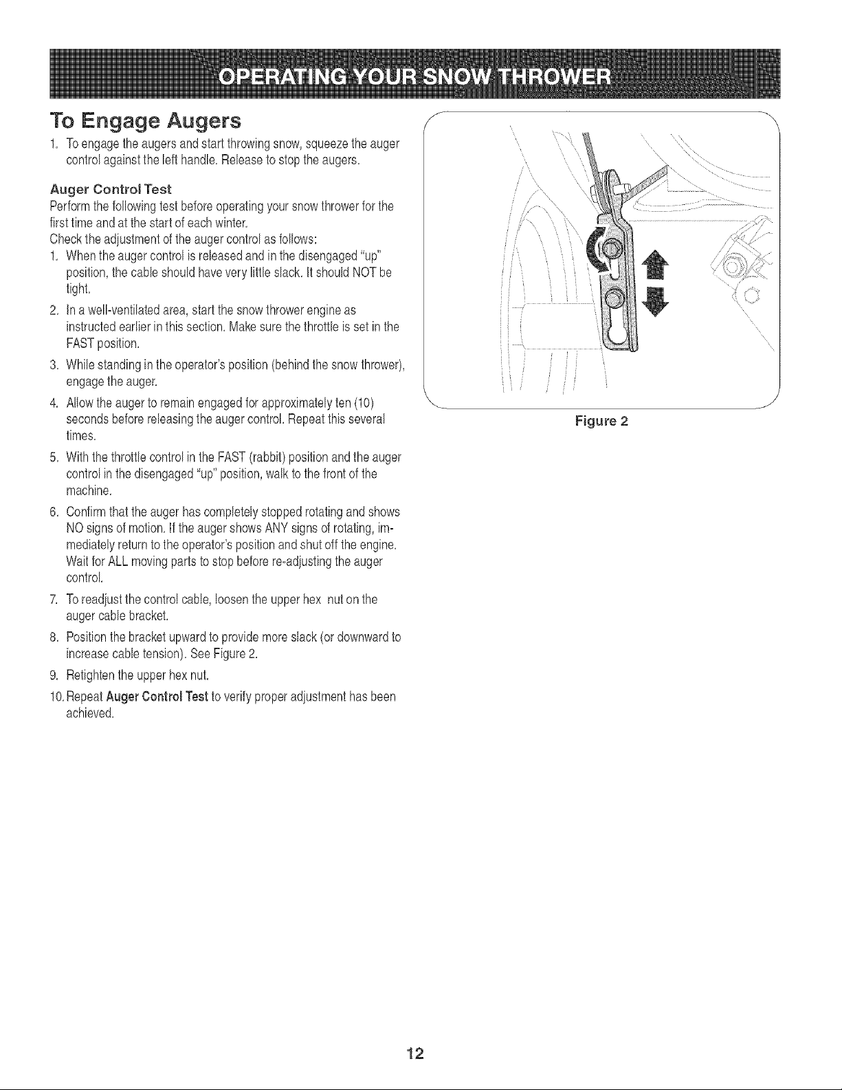
7, Toreadiustthecontrol cable,loosenthe upperhex nuton the
augercabb bracket,
8, Positionthebracketupwardto providemoreslack(or downwardto
increasecabb tension),See Figure2,
9, Retightenthe upper hexnut,
10,RepeatAuger Control Testto verifyproperadiustmenthasbeen
achieved,
S
Figure 2
12
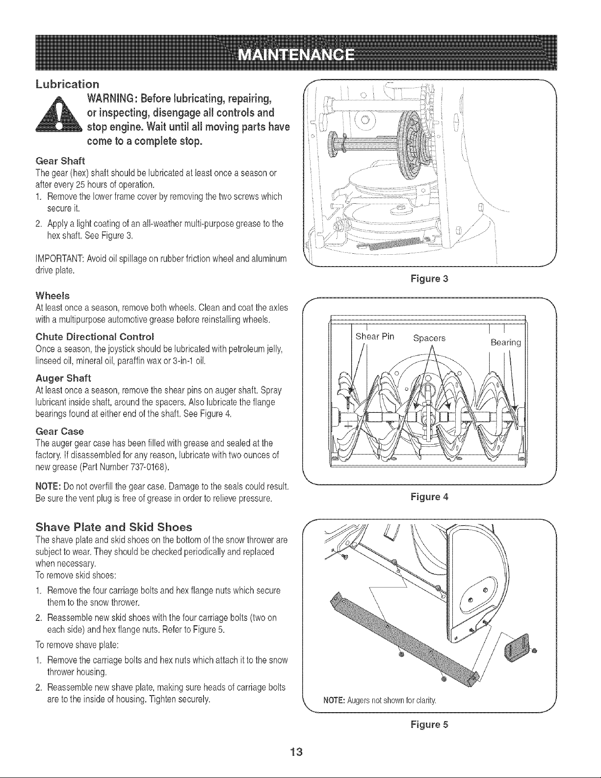
Lubrication
WARNING: Before Jubricating, repairing,
or inspecting, disengage aHcontrols and
stop engine. Wait until aH moving parts have
come to a complete stop.
Gear Shaft
Thegear (hex)shaft shouldbe lubricatedat leastoncea seasonor
afterevery25 hoursofoperation,
1, Removethe lowerframecover by removingthetwo screwswhich
secureit,
2, Applya lightcoatingof an all-weathermulti-purposegreaseto the
hexshaft, See Figure3,
iMPORTANT:Avoidoil spillageon rubberfrictionwheeland aluminum
driveplate,
Wheels
At leastonce a season,removebothwheels,Cleanandcoatthe axles
witha multipurposeautomotivegreasebeforereinstallingwheels,
Chute Directional Contro!
Oncea season,the ioysfickshouldbe lubricatedwith petroleumielly,
linseedoil, mineraloil, paraffinwaxor 3-ira1oil
Auger Shaft
At leastonce a season,removethe shearpinson augershaft,Spray
lubricantinsideshaft, aroundthe spacers,Alsolubricatethe flange
bearingsfoundat eitherendof the shaft,SeeFigure4,
Gear Case
Theauger gear casehas beenfilled withgreaseandsealedat the
factory,If disassembledfor anyreason,lubricatewithtwo ouncesof
newgrease(PartNumber737-0168),
NOTE: Donot overfillthe gearcase,Damageto the sealscould result,
Besurethe ventplugis free of greasein orderto relievepressure,
Shave P_ate and Skid Shoes
Theshave plateand skid shoesonthe bottomof the snowthrowerare
subiectto wear,They shouldbecheckedperiodicallyandreplaced
whennecessary,
Toremoveskid shoes:
1, Removethe four carriagebolts and hexflange nutswhich secure
themto thesnow thrower,
2, Reassemblenewskid shoeswith the fourcarriagebolts(twoon
eachside)and hexflangenuts,Referto Figure5,
Toremoveshave plate:
1, Removethe carriageboltsand hexnuts whichattach it to the snow
throwerhousing,
2, Reassemblenewshaveplate,makingsureheadsof carriagebolts
areto the insideof housing,Tightensecurely,
Si 'i
'i
\
\
7
Figure 3
,I-
S
t ]
Bearing
Figure 4
NOTE:Augersnot shownfor clarity.
Figure 5
13
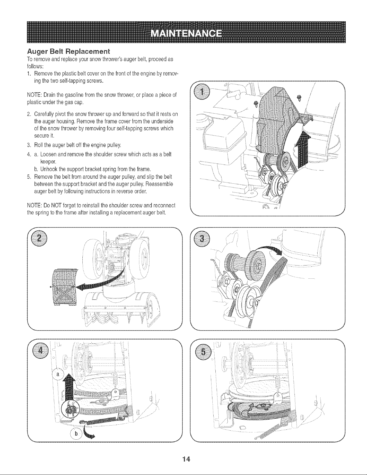
Auger Belt Replacement
To removeand replaceyoursnowthrower'saugerbelt,proceedas
follows:
1, Removetheplasticbelt coveron thefront of the engineby remov-
ingthe two selfqappingscrews,
NOTE:Drainthe gasolinefrom the snowthrower,or placea piece of
plasticunderthe gas cap,
2, Carefullypivotthe snowthrowerup andforwardso that it restson
the augerhousing,Removethe framecoverfromthe underside
of the snowthrowerby removingfourself-tappingscrewswhich
secureit,
3, Rollthe auger beltoff the enginepulley,
4, a, Loosenand removethe shoulderscrewwhich actsas a belt
keeper,
b, Unhookthesupportbracketspringfromthe frame,
5, Removethebelt from aroundthe augerpulley,andslip the belt
betweenthe support bracketandtheauger pulley,Reassemble
augerbelt by followinginstructionsin reverseorder,
NOTE:DoNOTforgetto reinstallthe shoulderscrewand reconnect
the springto theframeafterinstallinga replacementaugerbelt,
/
/
/
i
J \
J
J
14
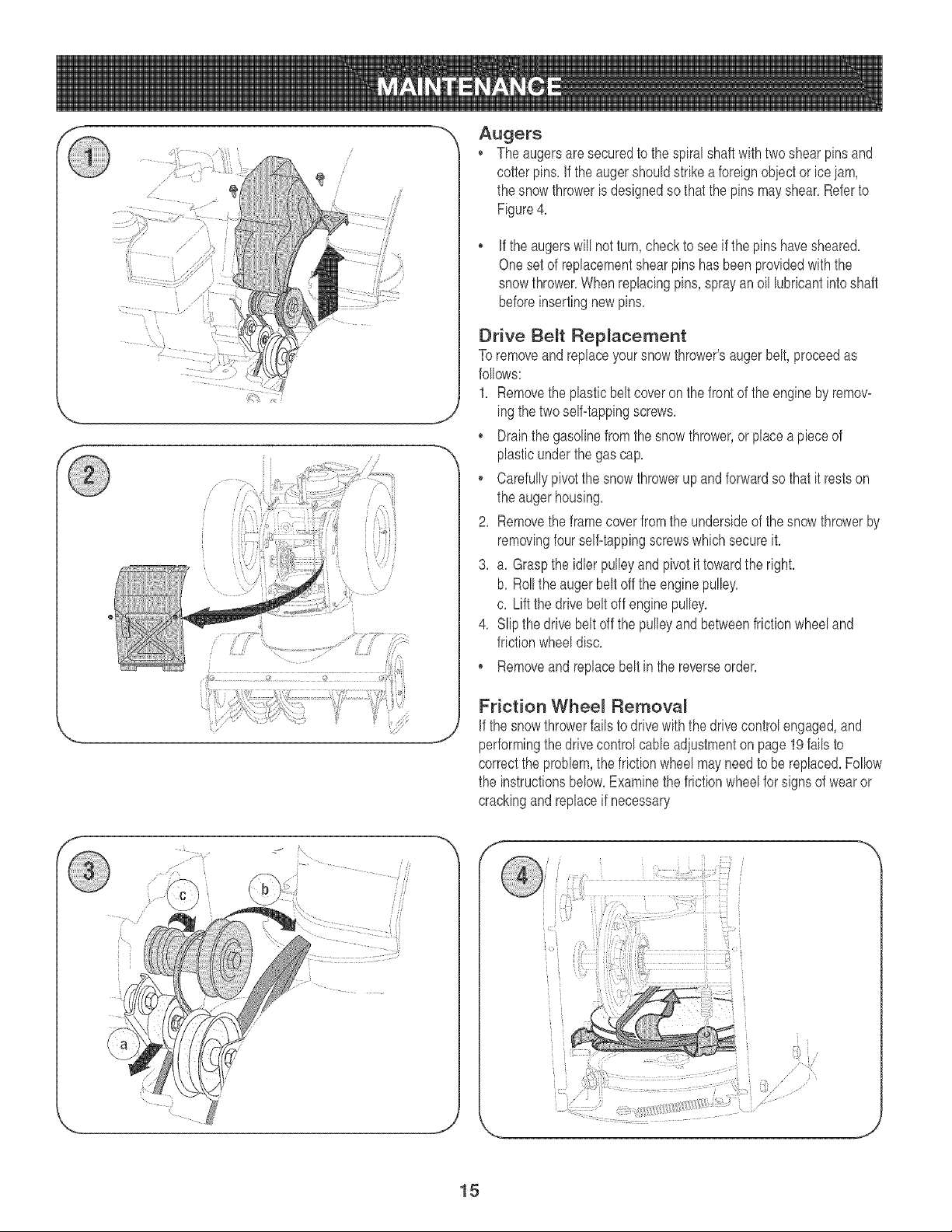
Augers
The augersare securedto the spiralshaftwithtwo shearpinsand
cotter pins.if the augershouldstrikeaforeignobjectorice iam,
the snow throwerisdesignedso thatthe pinsmayshear.Referto
Figure4.
if the augerswill notturn,checkto see if the pinshavesheared.
Onesetof replacementshearpins has beenprovidedwith the
snowthrower.Whenreplacingpins, sprayan oillubricantintoshaft
beforeinsertingnewpins.
Drive Belt Replacement
To removeand replaceyour snowthrower'saugerbelt, proceedas
follows:
1. Removethe _lasticbeltcoveron the frontof the engineby remov-
ing thetwo self-tappingscrews.
Drainthe gasolinefrom the snowthrower,or placeapieceof
plasticunder the gascap.
o Carefullypivot thesnowthrowerupandforwardso that it restson
the auger housing.
2. Removethe framecoverfromthe undersideof the snowthrowerby
removingfour self-tappingscrewswhichsecureit.
3. a. Graspthe idler pulleyandpivotit towardthe right.
b. Rollthe augerbelt offthe enginepulley.
c. Liftthe drivebeltoff enginepulley.
4. Slip the drive beltoff the pulleyand betweenfrictionwheeland
frictionwheeldisc.
* Removeand replacebeltin the reverseorder.
Friction Whee_ Remova_
Ifthe snowthrowerfails to drivewith the drivecontrolengaged,and
performingthe drivecontrolcable adiustmenton page19failsto
correctthe problem,the frictionwheelmay needto be replaced.Follow
the instructionsbelow.Examinethe frictionwheelfor signs of wearor
crackingand replaceif necessary
f
...._-.i_I'
J
15
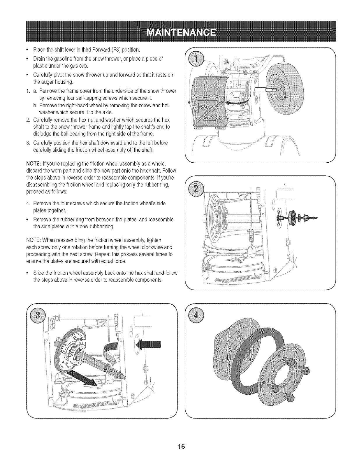
Placetheshift leverin thirdForward(F3) position,
Drainthe gasolinefrom thesnowthrower,or placea pieceof
plasticunderthe gascap,
Carefullypivotthe snowthrowerup and forwardso that it restson
the augerhousing,
1, a, Removethe frame coverfrom the undersideof the snow thrower
by removingfourself-tappingscrewswhich secureit,
b, Removethe right-handwheelby removingthe screwand bell
washerwhichsecureit to theaxle,
2, Carefullyremovethe hex nutandwasherwhichsecuresthe hex
shaftto the snow throwerframe and lightlytap the shaft'sendto
dislodgethe ballbearingfromthe rightside ofthe frame,
3, Carefullypositionthe hexshaftdownwardand to the leftbefore
carefullyslidingthefrictionwheelassemblyoff the shaft,
NOTE: if you'rereplacingthe frictionwheelassemblyas a whole, '_
discardthe wornpartand slidethe newpart ontothe hexshaft,Follow
the stepsabovein reverseorderto reassemblecomponents,if you're f
disassemblingthe frictionwheeland replacingonly the rubberring,
proceedas follows:
4, Removethefour screwswhichsecurethe frictionwheel'sside
platestogether,
, Removetherubberringfrombetweenthe plates,and reassemble
the sideplateswitha newrubberring,
NOTE:Whenreassemblingthefrictionwheelassembly,tighten
eachscrewonlyone rotationbeforeturningthe wheelclockwiseand
proceedingwith the nextscrew,Repeatthisprocessseveraltimesto
ensurethe platesaresecuredwithequalforce,
Slidethefrictionwheelassemblybackonto the hexshaftandfollow
the stepsabovein reverseorder to reassemblecomponents,
J
J \
J
16
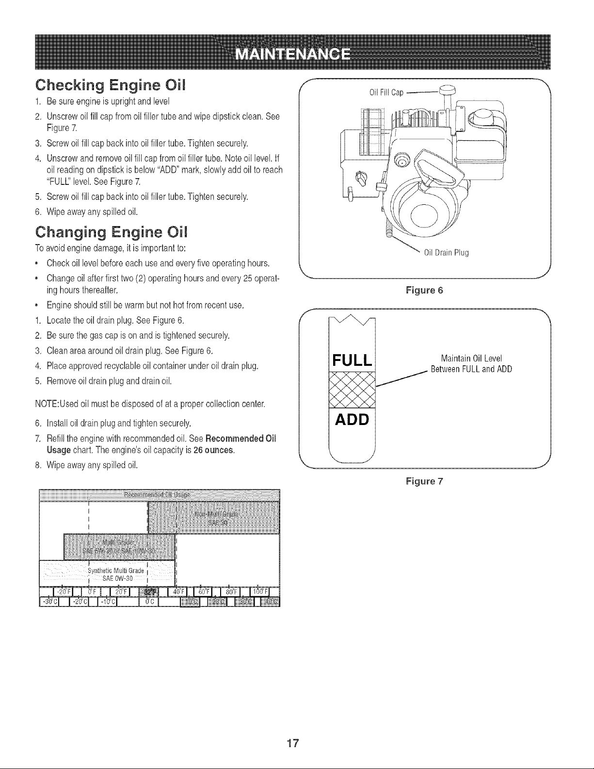
Checking Engine Oil
1. Be sureengineis uprightand level
2. Unscrewoil fill capfromoil fillertube andwipedipstickclean.See
Figure7.
3. Screwoil fill cap backinto oil filler tube.Tightensecurely.
4. Unscrewand removeoilfill cap fromoilfiller tube. Noteoil level If
oil readingon dipstickis below"ADD"mark,slowlyaddoil to reach
"FULl" level See Figure7.
5. Screwoil fill cap backinto oil filler tube.Tightensecurely.
6. Wipeawayanyspilledoil
Changing Engine Oil
Toavoidenginedamage,it is importantto:
• Checkoil levelbeforeeachuse and everyfive operatinghours.
• Changeoil afterfirst two(2) operatinghoursand every25 operat-
inghoursthereafter.
• Engineshouldstill be warm but nothot fromrecentuse.
1. Locatetheoil drainplug.See Figure6.
2. Be surethe gas cap is onand is tightenedsecurely.
3. Cleanareaaroundoil drainplug.See Figure6.
4. Placeapprovedrecyclableoil containerunderoil drain plug.
5. Removeoil drainpluganddrainoil
NOTE:Usedoil mustbe disposedof at a propercollectioncenter.
6. Installoildrainplugandtightensecurely.
7. Refillthe enginewith recommendedoil SeeRecommendedOil
Usagechart.The engine'soilcapacityis 26 ounces.
8. Wipeawayanyspilledoil
iiiiiiiiiiiiiiiiiiiiiiiiiiiiiiiiiiiiiiiiiiiiiiiiiiiiiiiiiiiilllllllllllllllllllllllllllllllllllllli!!ii_i_i_i_i_i_i_iii_i!ii_iiiiii__i_ iiiiliiiiiiiiiiiiiiilliiliiiii¸iiiiilliiiiiiiii!ii_iiiiiiiiii!iiiilliiii!i:iiiiilliiiiiliii!iiiiiii iii!
Oil Fill Cap I
Oil Drain Plug
Figure 6
FULL
ADD
MaintainOilLevel
_ BetweenFULLandADD
Figure 7
I I
17
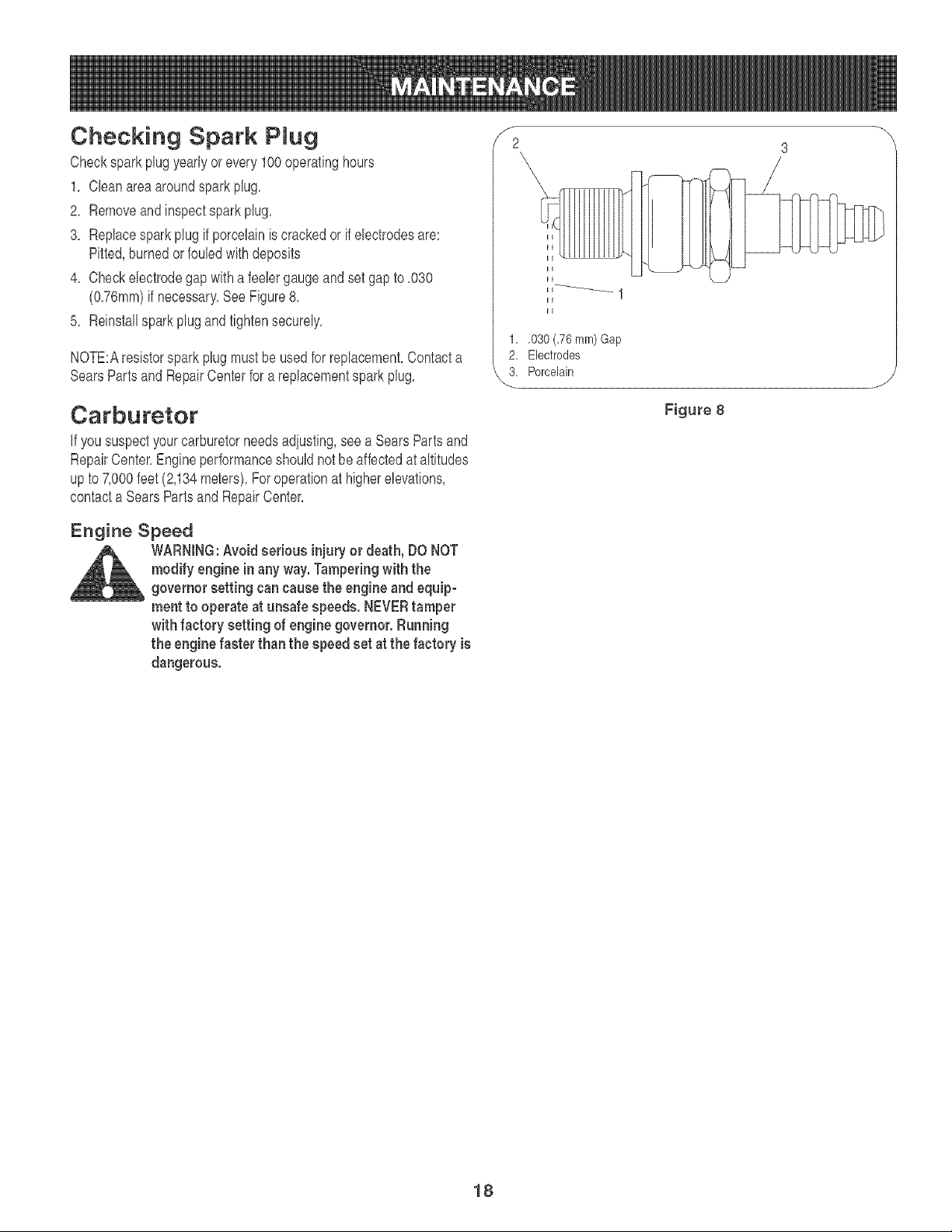
Checking Spark PRug
Checksparkplug yearlyor every 100operatinghours
1, Cleanareaaroundsparkplug,
2, Removeand inspectspark plug,
3, Replacespark plug if porcelainiscrackedor if electrodesare:
Pitted,burnedor fouledwithdeposits
4, Checkelectrodegap with a feelergaugeandset gap to ,030
(O,76mm)if necessary,See Figure8,
5, Reinstallspark plugand tightensecurely,
NOTE:Aresistorspark plug mustbe usedfor replacement,Contacta
SearsPartsand RepairCenterfor a replacementsparkplug,
Carburetor
if yoususpectyourcarburetorneedsadjusting,seea SearsParts and
RepairCenter,Engineperformanceshouldnot beaffectedat altitudes
upto 7,000feet(2,134meters),Foroperationat higherelevations,
contacta SearsPartsand RepairCenter,
Engine Speed
WARNING:Avoid serious injury or death, DO NOT
modify engine in any way.Tamperingwith the
governor setting can cause the engine and equip-
ment to operate at unsafe speeds. NEVERtamper
with factory setting of engine governor. Running
the engine faster than the speed set at the factory is
dangerous.
f
2
1. ,030 (.76 ram) Gap
2. Electrodes
3. Porcelain
Figure 8
18
Auger Control Adjustment
Referto AugerControlTeston Page12to adiustthe augercontrol
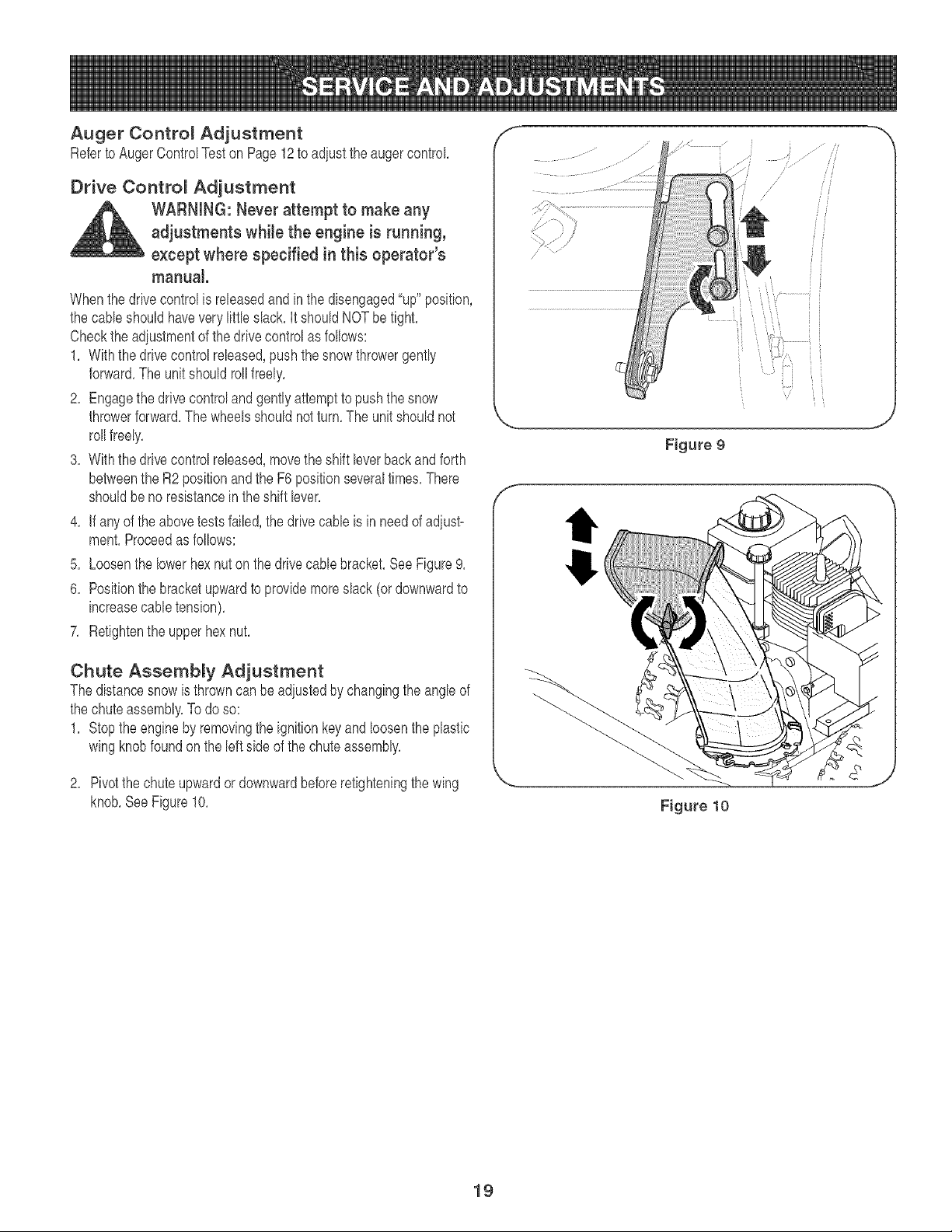
Drive Control Adjustment
WARNING: Never attempt to make any
adjustments while the engine is running,
except where specified in this operator's
manual
When thedrive controlis releasedand in the disengaged"up"position,
the cabb shouldhavevery littb slack,It shouldNOTbe tight,
Checkthe adiustmentof the drivecontrolas fo[bws:
1, With thedrive controlreleased,pushthe snowthrowergently
forward,The unitshouldrollfreely,
2, Engagethe drivecontroland gentlyattemptto pushthe snow
throwerforward,The wheelsshouldnotturn,The unitshouldnot
roltfreely,
8, With thedrive controlreleased,movethe shift leverbackandforth
betweenthe R2 positionandthe F6 positionseveraltimes,There
shouldbe no resistancein the shift lever,
4, If anyof the abovetestsfailed,thedrive cabteis in needof adiust-
ment,Proceedas foIIows:
5, Loosenthe lowerhexnut on thedrivecablebracket,SeeFigure9,
6, Positionthe bracketupwardto providemoreslack (or downwardto
increasecabletension),
7, Retightenthe upper hexnut,
Chute Assembly Adjustment
The distancesnowis throwncan bead}ustedby changingthe angleof
the chuteassembly,Todo so:
1, Stopthe engineby removingthe ignitionkeyand loosenthe plastic
wingknobfoundon the [eftsideof the chuteassembly,
2, Pivotthe chuteupwardordownwardbeforeretighteningthe wing
knob,SeeFigure10,
f
,.. j
Figure 9
Figure 10
19
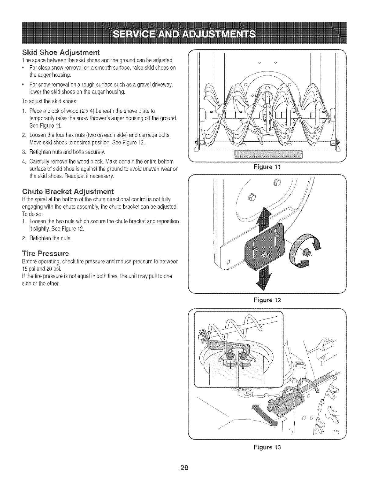
Skid Shoe Adjustment
Thespace betweenthe skidshoesand thegroundcan beadiusted,
, Forclose snow removalon a smoothsurface,raiseskidshoeson
the augerhousing,
, Forsnow removalon a roughsurfacesuchas a graveldriveway,
lowerthe skid shoeson the augerhousing.
Toadiustthe skidshoes:
1. Race a blockof wood (2x 4) beneaththe shave plateto
temporarilyraisethe snowthrower'saugerhousingoffthe ground.
SeeFigure11.
2. Loosenthe four hexnuts(twooneachside) andcarriagebolts.
Moveskidshoestodesiredposition.See Figure12.
3. Retightennutsand boltssecurely.
4. Carefullyremovethe woodblock.Makecertaintheentire bottom
surfaceof skidshoe is againstthe groundto avoidunevenwearon
the skid shoes.Readjustif necessary.
Chute Bracket Adjustment
if the spiralat the bottomof the chute directionalcontrolis not fully
engagingwiththe chuteassembly,thechutebracketcan beadiusted.
Todo so:
1. Loosenthe twonutswhichsecurethechutebracketandreposition
it slightly.See Figure12.
2. Retightenthe nuts.
Tire Pressure
Beforeoperating,checktire pressureand reducepressureto between
15psi and 20 psi.
if the tire pressureis not equalin bothtires,the unit maypullto one
sideor the other.
Figure 11
J
Figure 12
0
Figure 13
2O
f
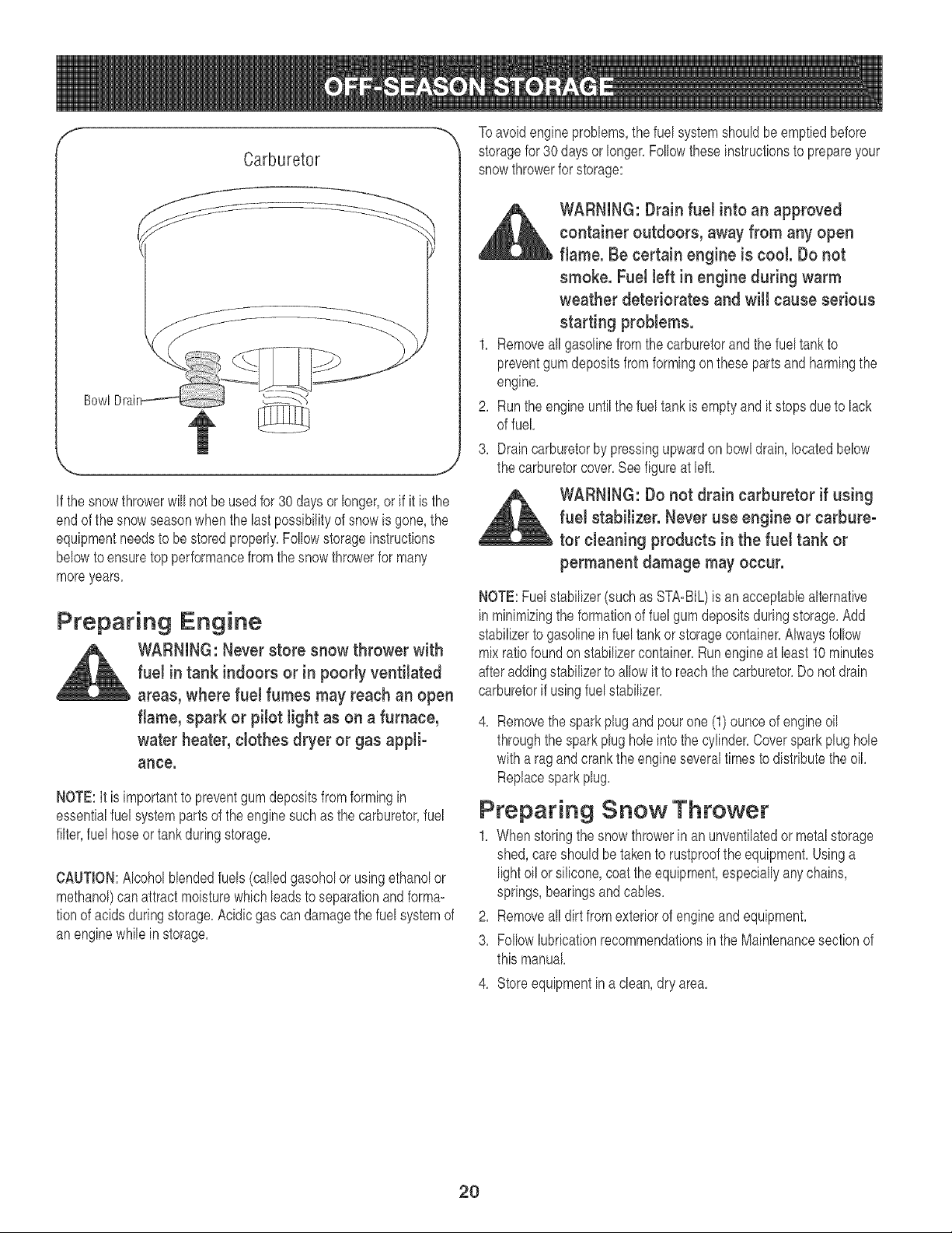
Carburetor
--.,,
Bowl
J
if the snowthrowerwill notbe usedfor 30daysor longer,or if it is the
endof the snowseasonwhenthe lastpossibilityof snowis gone,the
equipmentneedsto be stored properly,Followstorageinstructions
belowto ensuretop performancefrom thesnowthrowerfor many
moreyears,
Preparing Engine
WARNING: Never store snow thrower with
fuel in tank indoors or in pooHy ventiJated
areas, where fuel fumes may reach an open
flame, spark or pilot Jight as on a furnace,
water heater, clothes dryer or gas appli°
ante.
NOTE:It is importantto preventgum depositsfrom formingin
essentialfuelsystempartsof theenginesuchas the carburetor,fuel
filter,fuel hoseor tankduringstorage,
CAUTION:Alcoholbbnded fuels (calbd gasoholor usingethanolor
methanol)can attractmoisturewhich leadsto separationandforma-
tionof acidsduringstorage,Acidicgas candamagethe fuel systemof
anenginewhile in storage,
Toavoidengineproblems,the fuel systemshouldbeemptiedbefore
storagefor 30 days or longer,Followtheseinstructionsto prepareyour
snowthrowerfor storage:
,_ WARNING: Drain fuel into an approved
container outdoors, away from any open
flame. Be certain engine is cool. Do not
smoke. Fuel left in engine during warm
weather deteriorates and will cause serious
starting problems.
1, Removeall gasolinefromthecarburetorand the fuel tankto
preventgumdepositsfrom formingon thesepartsandharmingthe
engine,
2, Run the engineuntilthe fuel tankis emptyandit stopsdueto lack
of fuel,
3, Draincarburetorby pressingupwardon bowldrain, locatedbelow
the carburetorcover,See figureat left,
WARNING: Do not drain carburetor if using
fuel stabilizer. Never use engine or carbure-
tor cleaning products in the fuel tank or
permanent damage may occur.
NOTE:Fuelstabilizer(suchas STA-BIL)isan acceptabbalternative
inminimizingthe formationof fuelgum depositsduringstorage,Add
stabilizerto gasolinein fuel tankorstoragecontainer,Alwaysfollow
mixratiofoundonstabilizercontainer,Runengine at bast 10minutes
afteraddingstabilizerto allow it to reachthe carburetor,Do not drain
carburetorif usingfuelstabilizer,
4, Removethe sparkplugand pourone(1)ounceof engineoil
throughthe sparkplughob intothe cylinder,Coversparkplug hob
witha ragandcrankthe engineseveraltimes to distributetheoil,
Replacesparkplug,
Preparing Snow Thrower
1, Whenstoringthe snow throwerin anunventilatedor metalstorage
shed,careshouldbetakento rustprooftheequipment,Usinga
light oil or silicone,coat the equipment,especiallyanychains,
springs,bearingsand cables,
2, Removeall dirtfrom exteriorof engineand equipment,
8, Follow lubricationrecommendationsinthe Maintenancesectionof
this manual,
4, Storeequipmentina clean,dry area,
2O
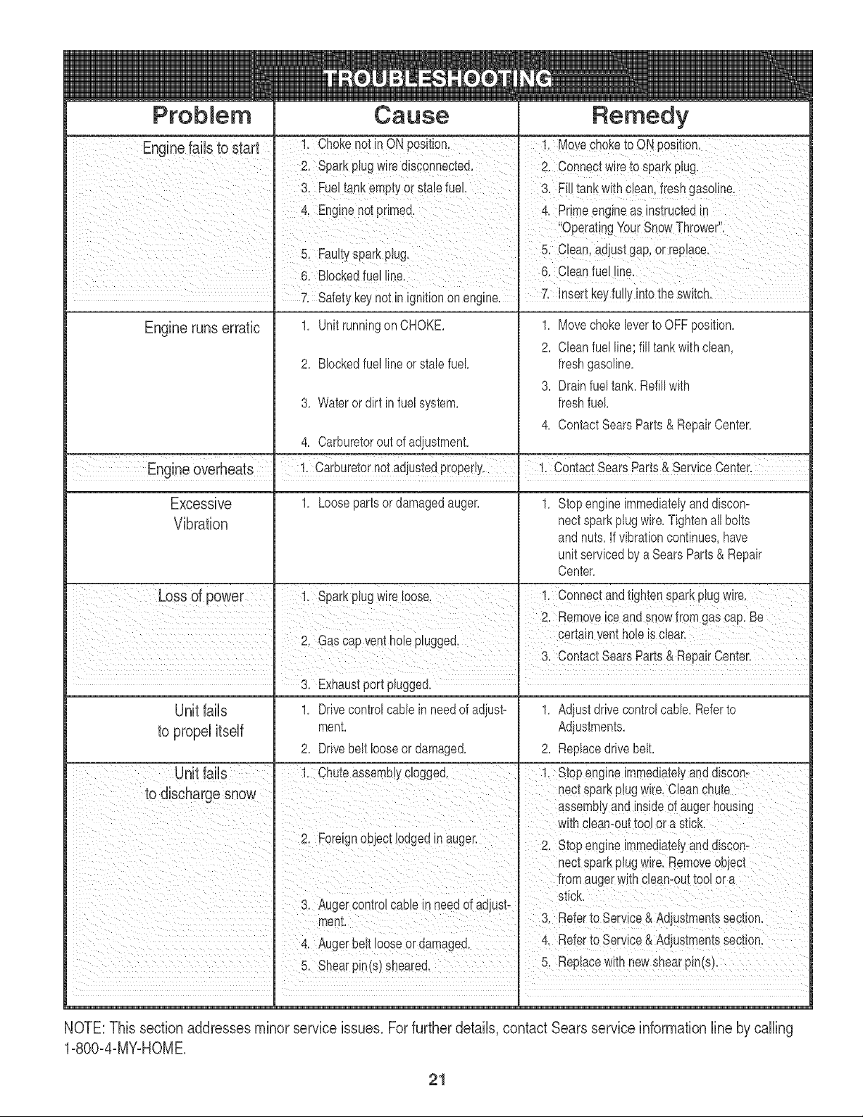
Problem
Engine runs erratic
Cause
1, Unit runningon CHOKE,
2, Blockedfuel lineorstab fuel
3, Wateror dirt in fuel system,
Remedy
1, Movechokebver to OFFposition,
2, Cban fuel line; fill tankwithclean,
freshgasoline,
3, Drainfueltank, Refillwith
freshfuel
4, Contact SearsParts& RepairCenter,
4, Carburetorout of adiustment,
EngineOverheats adjustedpioperiyI !i c0ntact %ars parts& ServiceCenter_
1, Looseparts or damagedauger,
Excessive
Vibration
1, Stopengineimmediatelyanddiscon=
nectsparkplugwire,Tightenall bolts
and nuts,If vibrationcontinues,have
unitservicedby a SearsParts& Repair
Center,
3. Exhaustport pBgged.
Unit fails
to propel itself
1, Drivecontrolcablein needof adiust=
ment,
2, Drivebelt looseor damaged,
1, Adiust drivecontrolcable,Referto
Adiustments,
2, Replacedrive belt,
NOTE: This section addressesminor service issues. For further details, contact Sears service information line by calling
1=800=4=MY=HOME
21

23
Q
"'--.
24

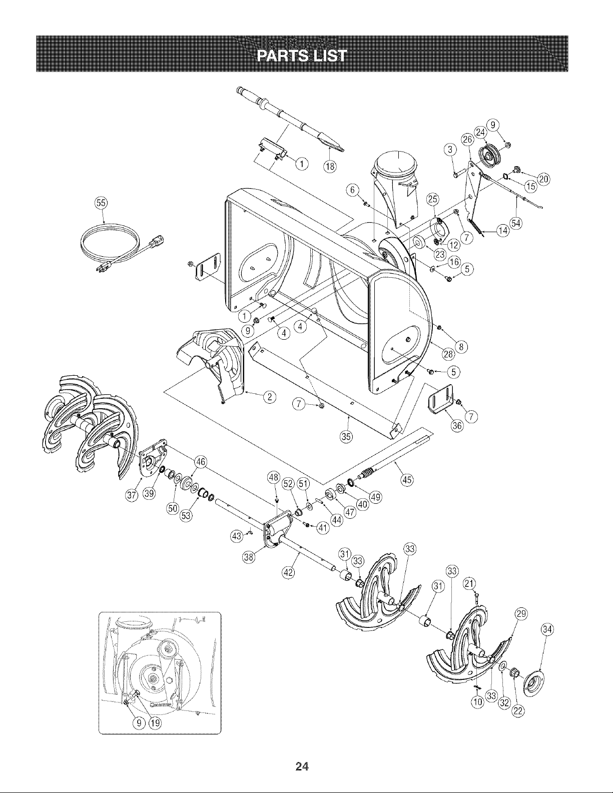
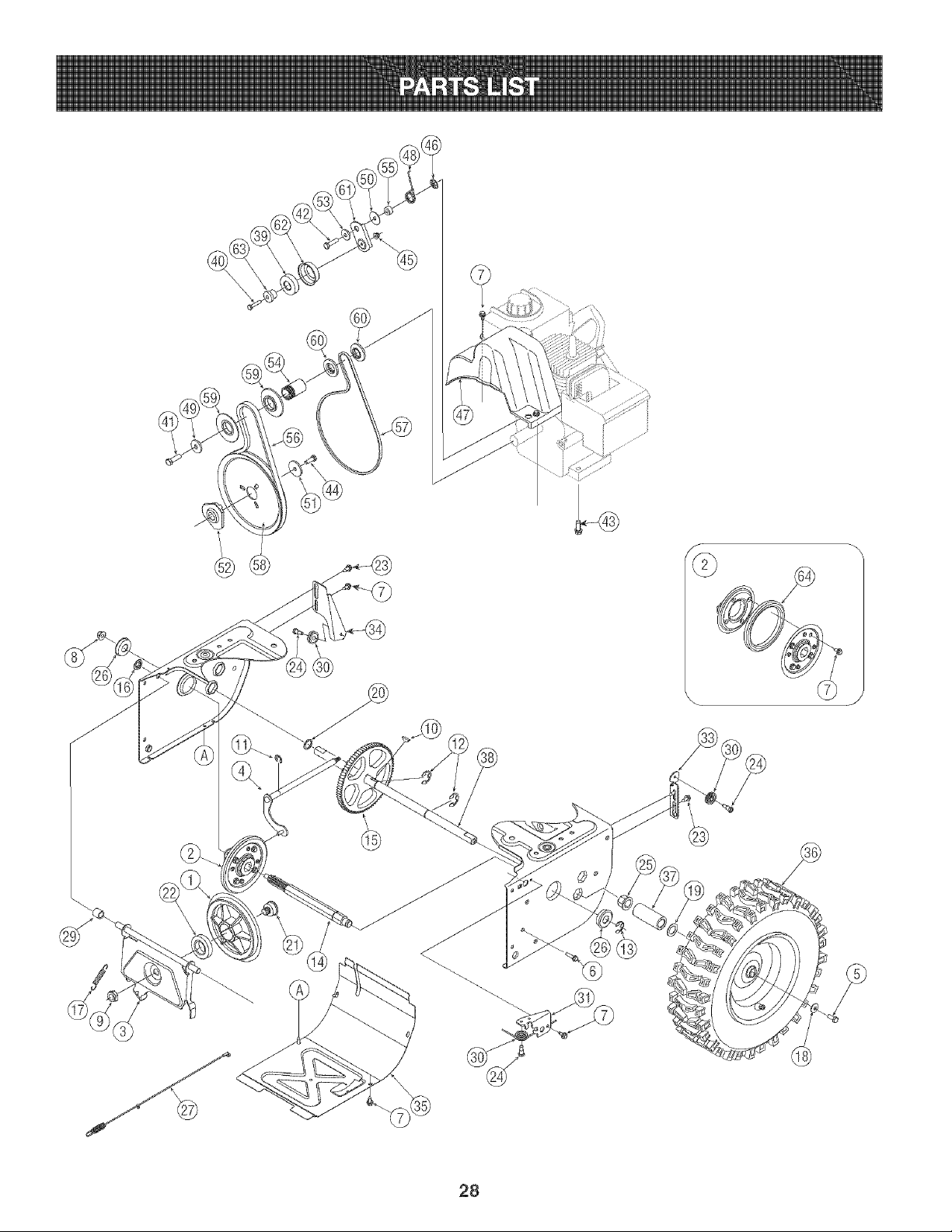
Craftsman 5.5 HP Snow Thrower Model 247.88355
1, 731-2635 SnowRemovalToolMount
2, 684-04057 ImpellerAssembly,12"Dia,
3, 710-0347 HexScrew,3/8-16,1,75,Gr5
4, 710-0451 Bolt,Carriage,5/16-18,,750Grl
5, 710-0604A Screw, 5/16-18,0,625
6, 710-0703 Screw,Carriage,1/4-20,,750,Gr5
7, 712-04063 Nut,FlangeLock,5/16-18,Nylon
8, 712-04064 Nut,FlangeLock,1/4-20,Nylon
9, 712-04065 Nut,FlangeLock,3/8-16,Nylon
10, 714-04040 CotterPin,Bowqie
11, 725-0157 CaNe,Tie, 3/16x ,05x 7,4
12, 726-04012 Nut,Push-on,,25 Dia
13, 731-04705 Chute,AdapterS"Dia
14, 732-0611 Spring,Extension,,38 OD x 3,6
15, 736-0174 Washer,Wave,,625x ,885x ,015
16, 736-0159 Washer,349 x ,879x ,063
17, 736-0463 Washer,Flat,,25 x ,630x ,0515
18, 731-2643 SnowRemovaITool
19, 738-0143 Screw,Shoulder,,498x ,340,3/8-16
20, 738-0281 Screw,Shoulder,,625x ,17,3/8-16
21, 738-04124A ShearPin, ,25x 1,50
22, 741-0245 Bearing,Hex Rangex ,75ID
23, 741-0309 Bearing,Ball,,75 ID x 1,85OD
24, 756-0981A FlatPulley,Idler, 2,75OD
25, 790-00075 Housing,Bearing,1,85ID
26, 790-00080 Bracket,Auger Idlerw/Brake
27, 618-04171 GearboxAssembly,Auger,24"
28, 684-04069 HousingAssembly,Auger24"
29, 684-04107 SpiralAssembly,LH
30, 684-04108 SpiralAssembly,RH
31, 731-04870 Spacer,1,25OD x ,75 ID x 1,00
32, 736-0188 Washer,Flat, ,76x 1,49x ,06
33, 741-0493A Bushing,Range, ,800 IDx ,910OD
34, 790-00087A Housing,1"Hex Bearing
35, 790-00120 ShavePlate,2,25x 23,66
36, 784-5580 Slide Shoe
37, 719-0319 Housing,Auger,RH Reduced
38, 719-0320 Housing,Auger,LH Reduced
39, 721-0179 Seal,Oil, ,7501D
40, 741-0662 Bearing,Range, ,75IDx 1,00ODx ,59
41, 710-0642 Screw,Self4apping,1/4-20,0,750
42, 711-04285 Axle,Auger,24"
43, 714-0161 Key,Hi-pro3/16x 5/8
44, 715-04021 Pin,Dowel,,25OD x 1,2
45, 717-04126 Shaft,Worm,75OD
46, 717-0528A Gear,Worm20T
47, 718-04071 Collar,Thrust
48, 721-0325 Plug,1/4x,437
49, 721-0327 Seal,Oil, ,75x 1x ,131
50, 736-0351 Washer,Flat, ,760ID x 1,50D
51, 736-3084 Washer,Flat, ,51x 1,12
52, 741-0663 Bearing,Range, ,75IDx 1,00ODx ,925
53, 741-0661A Bearing,Range,,75ID x 1,00ODx ,975
54, 746-04230 ClutchCaNe,Auger,47,23"
55, 629-0071 ExtentionCord, 110V
25
©
26

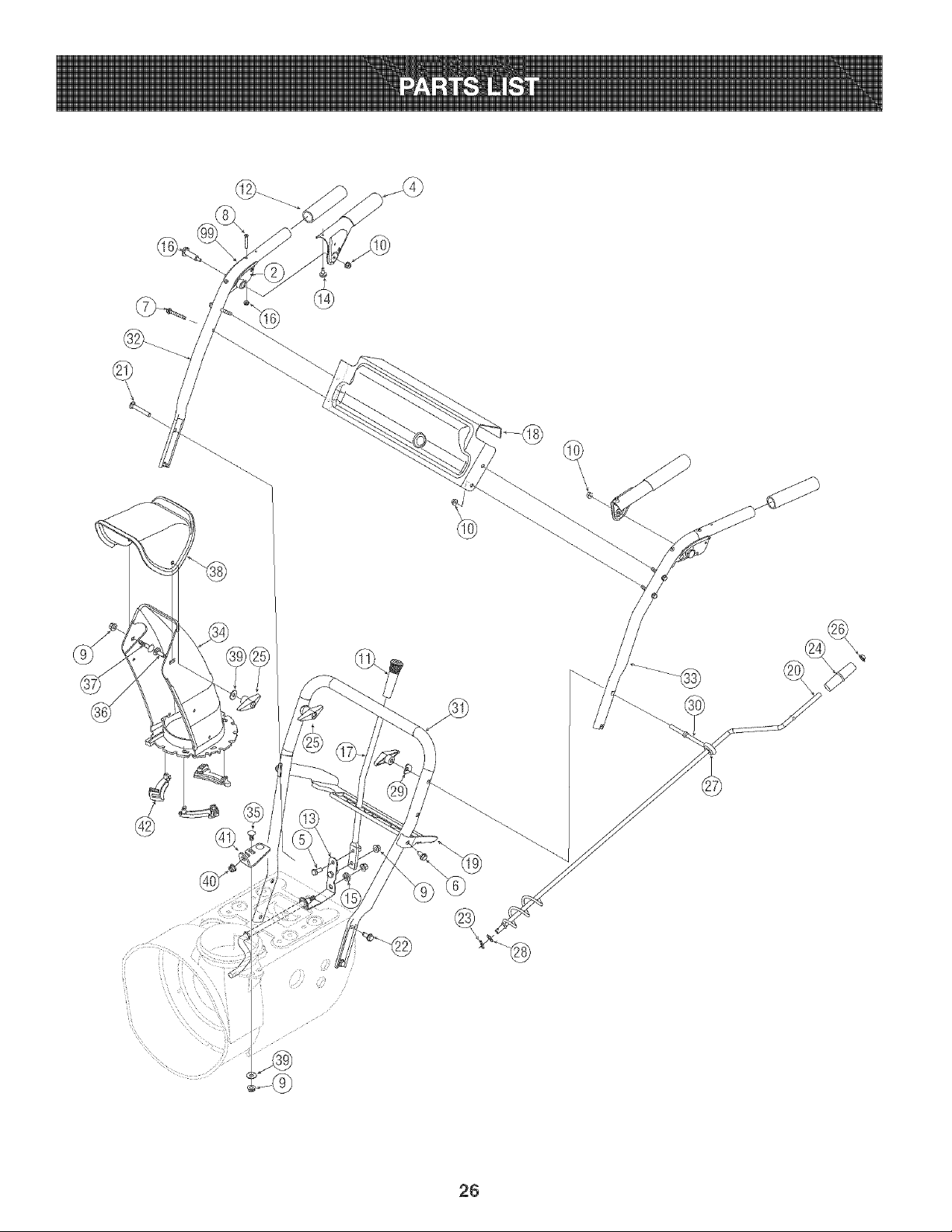
Craftsman 5.5 HP Snow Thrower Model 247.88355
1, 631-04133 HandleAss'y,Lock LH
2, 631-04134A HandleAss'y,Lock,RH
3, 684-04106A HandleAss'y,EngagementLHBlack
4, 684-04105A HandleAss'y,Engagement,RHBlack
5, 710-0376 Screw,Selfqapping,5/16-18,,625
6, 710-0604A Screw,Selfqapping,5/16-18,1,0
7, 710-0606 Screw,Selfqapping,1/4-20,1,50
8, 710-1233 Screw,Machine,#10-24,1,375
9, 712-04063 Nut,FlangeLock,5/16-18,Nylon
10, 712-04064 Nut,FlangeLock,1/4-20,Nylon
11, 720-0223 Grip,0,5 ID x 3,45
12, 720-0274 Grip,1,0ID x 5,0
13, 732-04205 SpringLever,Shift
14, 735-0199A Bumper,Rubber,,62 ODx ,22
15, 736-0509 Washer,Flat,,350 sq, x ,72x ,134
16, 738-04122 Screw,Shoulder,,437x 1,345,1/4-20
17, 747-04243 Lever,Shift
18, 790-00100 Panel,Handle,D-Style
19, 790-00187 Panel,Speed Selector(5 FW,2 RV)
20, 684-04104 CrankAssembly,Chute
21, 710-0449 Screw,Carriage,5/16-18,2,25, Gr5
22, 710q260A Screw,5/16-18,0,75,Gr5
23, 714-0104 Pin,Cotter,,072x 1,13
24, 720-0201A CrankKnob,1,0Diameterx 3,2,Black
25, 720-0284 KnobAssembly,Wing Nut,5/16-18
26, 726-0100 Cap,Push,3/8 Rod
27, 735-0234 Grommet,,44 IDx ,94 OD x ,50
28, 736-0185 Washer,Flat, ,375x ,738x ,063
29, 736-0451 Washer,Saddle,320 x ,93x ,060
30, 747-04263 EyeBolt,ChuteCrank
31, 749-04138 Handle,Lower
32, 749-04141 Handle,Upper,RH
33, 749-04142 Handle,Upper,LH
34, 731-04912A Chute,Lower,5,0 Diameter
35, 710-0276 Bolt, Carriage,5/16-18,1,0
36, 710-04071 Bolt, Carriage,5/16-18,1,0,Custom
37, 710-0451 Bolt, Carriage,5/16-18,,750
38, 731-04426A Chute,Upper,w/Label
39, 736-0159 Washer,349ID x ,879OD x ,063
40, 741-0475 Bushing,Plastic,,380
41, 784-5647 Bracket,ChuteCrank
42, 731-04869 Chute,Range Keeper
27
@
28

Craftsman 5.5 HP Snow Thrower Model 247.88355
1, 756-04177 Disc,FrictionWheel
2, 684-04153 FrictionWheelAssembly,5,50D
3, 684-04154 SupportBracketAss'y,FrictionWheel
4, 684-04156 ShiftAssembly,Rod
5, 710-0627 HexScrew,5/16-24,,750,Gr5, Lock
6, 710-0788 Screw,1/4-20,1,000
7, 710-1652 Screw1/4-20x,625
8, 712-04065 Nut,FlangeLock,3/8-16,GrF,Nylon
9, 712-0413 Nut,JamLock,5/8-18,Gr5, Nylon
10, 714-0126 Key,Hi Pro,3/16x 3/4 Dia,
11, 716-0104 E-ring,,500Dia,
12, 716-0136 E-ring,Retaining,,875Dia,
13, 716-0231 E-ring,,750Dia,
14, 717-04209 Hex Shaft,,8125,7-Tooth
15, 717-04230 Gear,80-Tooth
16, 726-0221 SpeedNut, ,500
17, 732-0264 ExtensionSpring
18, 736-0242 Washer,Bell, ,340x ,872x ,060
19, 736-0287 Washer,Flat,,793x 1,24x ,060
20, 736-04161 Washer,Flat,,75 x 1,00x ,060
21, 738-04164 Pin,FrictionDisc
22, 741-04098 Ball Bearing,30 x 55 x 13
23, 738-04184 Screw,Shoulder,,373x ,105,1/4-20
24, 738-0924 Screw,1/4-28,,375
25, 741-0245 Bearing,Rex Rangex ,75ID
26, 741-0563 Bearing,Ball, 17x 40 x 12
27, 746-04229 ClutchCaNe,Wheel,44,95"
28, 746-04230 ClutchCaNe,Auger,47,23"
29, 748-0190 Spacer,,508 IDx ,75ODx ,68
30, 756-0625 Roller,CaNe
31, 790-00096 FrontGuide Bracket,AugerCaNe
32, 790-00180 Frame
33, 790-00206 GuideBracket,AugerCaNe
34, 790-00207 GuideBracket,DriveCaNe
35, 790-00226 Cover,Frame
36, 634-04167A LHWheelAssembly,13x 4x 6 (Xqrac)
634-04168A RHWheel Assembly,13x 4 x 6 (Xqrac)
37, 731-04873 Spacer,1,25x ,75x 3,0
38, 738-04168 Axle, ,75x 22"
39, 741-0919 Ball Bearing
40, 710-0106 Rex Screw,1/4-20,1,25,Gr5
41, 710-0191 Rex Screw,3/8-24, 1,25,Gr8
42, 710-04520 Hex Screw,5/16-24,1,25,Gr5, Lock
43, 710-0654A Screw,Seres,3/8-16,1,00
44, 7104245B RexScrew,5/16-24,,875,Gr8, Lock
45, 712-04064 Nut,FlangeLock,1/4-20,GrF,Nylon
46, 726-04012 Nut,Push-on,,25 Dia,
47, 731-04792A Cover,Belt
48, 732-04308 Spring,Torsion,,850 IDx ,354
49, 736-0247 Washer,Flat, ,406x 1,25x ,157
50, 736-0362 Washer,Flat, ,330x 1,25x ,06
51, 736-0505 Washer,Flat, ,34x 1,50x ,150
52, 748-04053 Pulley,Adap,,75DiaW/dd
53, 748-04097 Spacer,Shoulder
54, 750-04303 Spacer,,875ID x 1,185OD
55, 750-04477 Spacer,,340 x ,750x ,360
56, 754-04050 Belt, AugerDrive
57, 754-04088 Belt,Wheel Drive
58, 756-04109 Pulley,Auger Drive,8,1x ,5
59, 756-04113 Pulley,Half,V x 2,600OD
60, 756-04179 Pulley,Half, 1/4-Vx 1,50D
61, 790-00208 IdlerBracket,Wheel Drive
62, 790-00230 Sleeve,Bearingldler
63, 750-04571 Spacer,Shoulder,,260x ,790x ,538
64, 735-04054 Rubber,FrictionWheel,5,50D
29
254
253
J
6OO
69
338"
3701
_26A
25A
2O0
203
25
285 93
90O
287 390 370K
3O
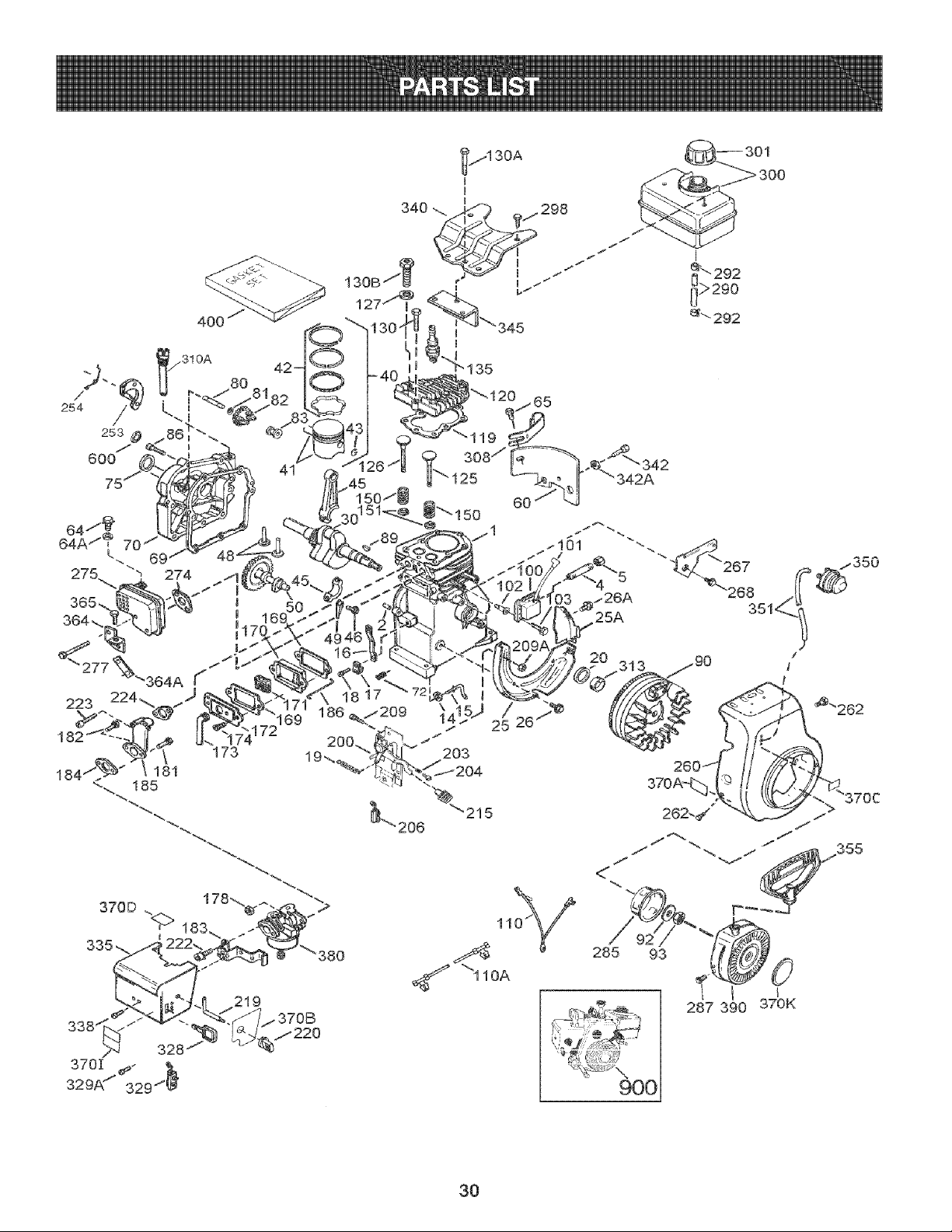
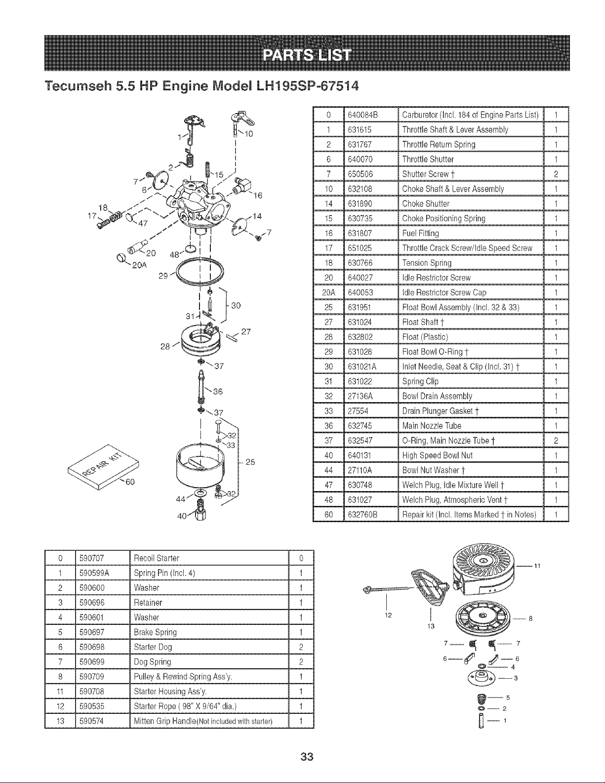
Tecumseh 5.5 HP Engine Model LH195SP-67514
1 36469A Cylinder(Incl.2,20,72& 125) 1
2 26727 DowelPin 2
5 30969 ExtensionCap (1/4-18NPT) 1
14 28277 Washer 1
15 31334 GovernorRod 1
16 37729 GovernorLever 1
17 31335 GovernorLeverClamp 1
18 651018 Screw,T-15,8-32 x 19/64" 1
19 31426 ThrottleSpring 1
20 32600 Oil Seal 1
25 36552 BlowerHousingBaffle(Incl. 2) 1
25A 35883 BaffleExtension 1
26 650802 Screw,1/4-20x 5/8" 2
26A 650926 Screw,8-32 x 21/64" 1
30 37842 Crankshaft 1
40 36073 Piston,Pin& RingSet (Std.) 1
40 36074 Piston,Pin& RingSet (.010") 1
40 36075 Piston,Pin& RingSet (.020") 1
41 36070 Piston& PinAss'y. (Std.)(In) 1
41 36071 Piston& PinAss'y. (.010"OS) Incl.43 1
41 36072 Piston& PinAss'y. (.020"OS) Incl.43 1
42 36076 RingSet (Std.) 1
42 36077 RingSet (.010"OS) 1
42 36078 RingSet (.020" OS) 1
43 20381 PistonPin RetainingRing 2
45 32875A ConnectingRodAss'y. (Incl.4) 1
46 32610A ConnectingRod Bolt 2
48 37670 Valve Lifter 2
49 32654 Oil Dipper 1
50 37671 Camshaft(MCR) 1
60 29745 BlowerHousingExtension 1
64 30063 Screw,T-30, 1/4-20x 1/2' 1
64A 8345 Washer 1
65 650128 Screw,10-24x 1/2"(1/4-18NPT x 4-3/4) 1
69 27677A * CylinderCoverGasket 1
70 34674C CylinderCover(Incl. 75thru 2
72 27642 Oil Plug 2
75 27897 Oil Seal 1
80 30574A GovernorShaft 1
81 30590A Washer 1
82 30591 GovernorGearAssembly(Incl. 1
83 30588A GovernorSpool 1
86 650488 Screw,1/4-20x 1-1/4" 7
101
102
103
110
110A
119
120
125
125
126
127
130
130A
130B
135
150
151
169
170
171
172
173
174
178
181
182
183
184
185
186
2OO
203
2O4
206
215
219
220
222
31
89 610961 FlywheelKey 1
90 611195 Flywheel 1
92 650815 BellevilleWasher 1
93 650816 FlywheelNut 1
100 34443C SolidState Ignition 1
610118 Spark PlugCover 1
651024 SolidState MountingStud 2
651007 Screw,T-15,10-24x 15/16" 2
35182 GroundWire 1
36874 GroundWire 1
36443 * CylinderHeadGasket 1
37675 CylinderHead (Incl.131) 1
36471 ExhaustValve(Std.) (Incl. 15) 1
36472 ExhaustValve(1/32"OS) (Incl.) 1
32644A IntakeValve(Std.) (Incl. 151) 1
650691 Washer 1
6021A Screw,5/16-18x 1-1/2" 2
650694A Screw,5/16-18x 2" 5
650818 Screw,5/16-18x 1-1/2" 1
35395 ResistorSpark Plug (RJ19LM) 1
31672 ValveSpring 2
31673 ValveSpring Cap 2
27234A *Valve CoverGasket121 2
27666 BreatherBody 1
31410 BreatherElement 1
34146 ValveCover 1
35350 BreatherTube 1
650783 Screw,10-24x 3/4" 2
29752 Nut& LockWasher,1/4-28" 2
650870 Screw,1/4-28x 1-11/16" 1
6201 Screw,1/4-28x 7/8" 1
34583A Chokebracket 1
26756 * CarburetorTo IntakePipe Ga 1
33691 IntakePipe 1
32698 GovernorLink 1
36677 ControlBracket(Incl.203thr 1
31342 CompressionSpring 1
651029 Screw,T-10,5-40 x 7/16" 1
610973 Terminal 1
35440 ControlKnob 1
34582 Choke Rod 1
35438 Choke Knob 1
28820 Screw,10-32x 1/2" 2
223 650664 Screw,1/4-20x 1-19/32" 2
224 33673A *Intake PipeGasket 1
253 36701 CompressionReleaseWeight 1
254 36702 CompressionReleaseSpring 1
260 35656A BlowerHousing 1
262 650737 Screw,1/4-20x 1/2" 2
267 34212 HoldDownBracket 1
268 30200 Screw,10-24x 9/16" 1
274 33670A *ExhaustGasket 1
275 35771A Muffler(Incl.274) 1
277 792005 Screw,1/4-20x 2-1/2" 2
285 36467A Starter Cup 1
287 650926 Screw,8-32 x 21/64" 2
290 30705 FuelLine 1
292 26460 FuelLineClamp 2
298 650665 Screw,1/4-15x 3/4" 2
900 35584 FuelTank (Incl.292 & 301) 1
301 37845 FuelCap 1
310 35556 Dipstick 1
311 37246 Oil FillPlug 1
312 27625 Oil FillPlug Gasket 1
313 34080 Spacer 1
328 35062 IgnitionKey 2
329 610973 Terminal 1
329A 651060 Screw,8-32x 23/64" 1
935 35072
938 650257
940 36247
942 30063
342A 650675
345 33344
350 570682A
951 32180C
355 590574
964 33333
364A 37673
965 650795
970A 36261
970B 35282
970C 36501
970D 36534
970! 37119
970K 36695
980 640084B
990 590742
996 33290E
396 730266
400 36444
600 651013
900 754336
CarburetorCover 1
Screw,8-32 x 5/16" 2
FuelTankBracket 1
Screw,T-30, 1/4-20x 1/2" 1
Washer 2
Heat Baffle 1
PrimerAssembly 1
PrimerLine 1
Starter Handle(Mitten Grip) 1
CarburetorCoverBracket 1
LockingPlate 1
Screw,10-24x 3/8" 1
InstructionDecal 1
SpeedControl Decal 1
PrimerDecal 1
CautionDecal 1
WarningDecal 1
Starter Decal 1
Carburetor(Incl. 184) 1
RewindStarter1 1
ElectricStarter Motor110Volt 0
ElectricStarterKit (Optional) tt o
* GasketSet 1
Washer 1
ReplacementShort Block, order71-999 1
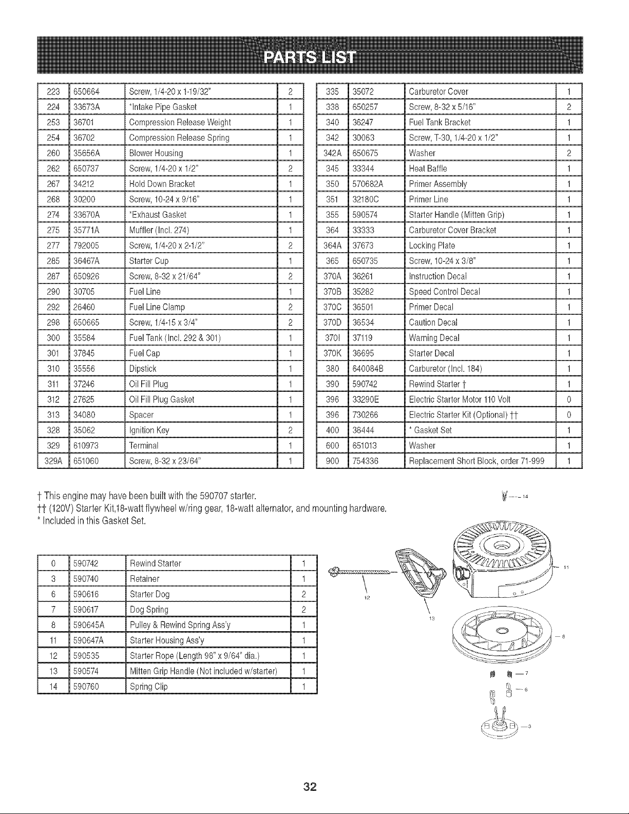
t This engine may have been built with the 590707 starter.
ff (120V) Starter Kit,18-watt flywheel w/ring gear, 18-watt alternator, and mounting hardware.
* Included in this Gasket Set.
0 590742 RewindStarter 1 _ '__
Retainer
Starter Dog
DogSpring
Pulley& RewindSpringAss'y
Starter HousingAss'y
Starter Rope(Length 98" x 9/64" dia.)
MittenGrip Handle(Not includedw/starter)
SpringClip
1
2
2
1
1
1
1
1
3 590740
6 590616
7 590617
8 590645A
11 590647A
12 590535
13 590574
14 590760
32
Tecumseh 5.5 HP Engine Model LH195SP-67514
=
17_
25
0 590707 RecoilStarter 0
1 590599A Spring Pin (Incl.4) 1
2 590600 Washer 1
3 590696 Retainer 1
4 590601 Washer 1
5 590697 Brake Spring 1
6 590698 StarterDog 2
7 590699 Dog Spring 2
8 590709 Pulley & RewindSpringAss'y. 1
11 590708 Starter HousingAss'y. 1
12 590535 Starter Rope( 98" X 9/64"dia.) 1
13 590574 Mitten Grip Handle(Notincludedwithstarter) 1
33
o
1
2
6
7
lO
14
15
16
17
18
2o
20A
25
27
28
29
3O
31
32
33
36
37
4O
44
47
48
6O
640084B Carburetor(Incl. 184of EngineParts List) 1
631615 ThrottleShaft & Lever Assembly 1
631767 Throttle ReturnSpring 1
640070 ThrottleShutter 1
650506 ShutterScrew1 2
632108 ChokeShaft & LeverAssembly 1
631890 ChokeShutter 1
630735 Choke PositioningSpring 1
631807 FuelFitting 1
651025 ThrottleCrack Screw/IdleSpeed Screw 1
630766 TensionSpring 1
640027 Idle RestrictorScrew 1
640053 Idle RestrictorScrewCap 1
631951 FloatBowl Assembly(Incl. 32 & 33) 1
631024 FloatShaft 1 1
632802 Float(Plastic) 1
631028 FloatBowl O-Ring1 1
631021A InletNeedle,Seat& Clip (Incl. 31)1- 1
631022 Spring Clip 1
27136A BowlDrainAssembly 1
27554 DrainPlungerGasket1 1
632745 MainNozzleTube 1
632547 O-Ring,MainNozzleTube1 2
640131 HighSpeedBowlNut 1
27110A BowlNutWasher1 1
630748 Welch Plug,Idle MixtureWell 1" 1
631027 Welch Plug,AtmosphericVent1" 1
632760B Repairkit (Incl. Items Marked1"inNotes) 1
,e 13 O__o
6
@ms
0--2
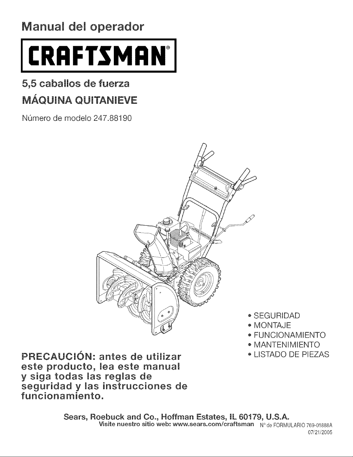
Manuam demoperador
[RAFTSMAN°
5,5 caballos de fuerza
MAQUINA QUITANIEVE
N0mero de modelo 247.88190
PRECAUCION: antes de utimizar
este producto, meaeste manual
y siga todas mas regmas de
seguridad y _as instrucciones de
funcionamiento,
o SEGURIDAD
MONTAJE
FUNCIONAMIENTO
MANTENIMIENTO
MSTADO DE PIEZAS
Sears, Roebuck and Co., Hoffman Estates, IL 60179, U.S.A.
o
Visite nuestro sitio web: www, sears,corn/craftsman N de FORMULARIO769-01888A
07/21/2005
Deciaraci6ndegarantia............................Pagina2
Acuerdodeprotecci6nparareparaciones_.P_gina2
Practbasoperaci6nseguras.....................Paginas3-5
Montaje......................................................Paginas6-7
Instruccionesdearranque/detenci6n............Paginas10-11
Operaci6n..................................................Pb,ginas8-12
Mantenimiento...........................................Paginas13-18
Servicioyajustes......................................P_ginas19-20
AImacenamientofueradetemporada.......P_gina21
Soluci6nde problemas.............................P_gina22
NOmerodeservicio Cubiertaposterior
GarantiadedoeaSosparalam_quinaquitanbveCraftsman
Durantedosahosapartirdelafechadecompra,sbmprequeaestam&quinaquitanbveselerealiceelserviciodemantenimbnto,lubricaci6n
ypuestaapuntodeacuerdoalasinstruccionesdelmanualdelpropbtaRo,Searsrepararb,sincargocualqubrdefectodemateRabsomanede
obra.Siestam_quinaquitanbveCraftsmanseutilizaparaprop6sitoscomercialesodealquiler,estagaranfiaseaplicas61odurante30diasa
partirdelafechadecompra.Estagaranthnocubre:
. Ebmentosdesechabbsquesedesgastanperelusenormal,incluyendoentreotros,zapatasantideslizantes,placaderaspadoybuiias.
• ReparacionesnecesaRasdebidoaabuseonegligenciadeloperador,incluyendoabolladuradelcigOeRalyfallapornorealizarmantenimbnto
delequipodeacuerdoconlasinstruccionescontenidasenelmanualdelpropbtario.
ELSERVlClODEGARANTiAESTADtSPONIBLEPARALOSUSUARiOSQUELLEVENLAM/_QUINAQUITANIEVECRAFTSMANAL
CENTRODEPARTESyREPARAClONSEARSMA,SCERCANODENTRODELOSESTADOSUNIDOS.
EstagaranfiaesvalidaOnbamentembntraselproductoseutilbedentrodelosEstadosUnidos.
PARAUBICARELCENTRODEPARTESYREPARAClONSEARSMASCERCANO0 PARAPROGRAMARELSERVlCIOTCCNICO,SIMPLE-
MENTECOMUNiQUESECONSEARSALTELEFONO1-800-4-MY-ROME@.
Estagaranthleotorgaderechosbgabsespecificos;ustedtambi6npuedetenerotrosderechos,loscualesvaHandeunestadoaotro.
SEARS,ROEBUCKANDCO.,[)/817WA,HOFFMANESTATES,IL60179
Acuerdos de protecci6n sobre reparaciones
Felicitacionespor haberrealizadouna adquisici6ninteligente.El
productoCraftsman@queha adquiridoest_diseRadoy fabrbado
parabrindarmuchosares de funcionambntoconfiable.Perocomo
todoslos productosa vecespuederequerirde reparaciones.Es en
ese momentocuandoel disponerde un acuerdode protecci6npara
reparacionesle puedeahorrardineroy probbmas.
A continuaci6nsedetallanlos puntosincluidosen el acuerdo:
. Servbio expertoprestadoper nuestros12.000especialistasen
reparacionesprofesionabs
. Servbio ilimitadosincargopara las pbzas y la manede obraen
todaslas reparacionescubbrtas
. Reemplazodelproductosi noesposibbrepararelproductocubbrto
• Descuentode 10%del precionormaldel servbio y de laspbzas
relacionadascon el mismoquenoestencubbrtas perel acuerdo;
ademb,s, 10%de descuentodel precionormalde laverificaci6nde
mantenimientopreventivo
. Ayudar@idaperteldono- asistenciatebf6nbaa cargodeunt@nbo
deSearsparalos productosquerequbrenreparaci6na domicilio,
adem_sdeuna ramaciOnconveniente
Adqubra ahoraunacuerdode protecci6npara reparacionesy
proteiasede probbmasy gastosinesperados.
Unavez adquiridoel aeuerdo,puedeprogramarelservieiocon
tan s61orealizaruna Ilamadatelef6niea.PuedeIlamarencualquier
momentodel dia o dela noehe,o programarun servicioen linea.
Searsdisponedem_sde 12.000espeeialistasen reparaeiones
profesionabsque tienenaccesoa m_s de 4,5 millonesde piezas
y accesoriosdegrancalidad.Esteesel tipo de profesionalismoen
el quepuedeeonfiarparaque le ayudea prolongarla vida Otildel
productorecientementeadquiRdoen los aRosporvenir,iAdquierahoy
su acuerdodeproteeci6nparareparaciones!
Seaplieandeterminadaslimitacionesy exclusiones.Paraobtener
informaci6nadieionaly preciosIlameal 1-800-827-6655.
Serviciode instalaci6nde Sears
Sideseasolieitarla instalaei6nprofesionalde Searsde aparatos
domestieos,dispositivosparaabRrportones,ealentadoresde aguay
otrosartieulosdomestieosimportantes,en losEstadosUnidosIlame
al 1-800-4-MY-HOME@
Cabaiios de fuerza :
Aceite del motor:
Combustible:
Bujias:
Motor:
5,5
SAE 5W=30
Gasolina sin plomoe
Champion@ RJ19LM
Tecumaeh LH195SP
NOmero de modeio ......................................................
NOmero de serie ...........................................................
Fecha de compra .........................................................
Regietre encima el n_mero del modelo, el nQmero
de eerie y la fecha de compra
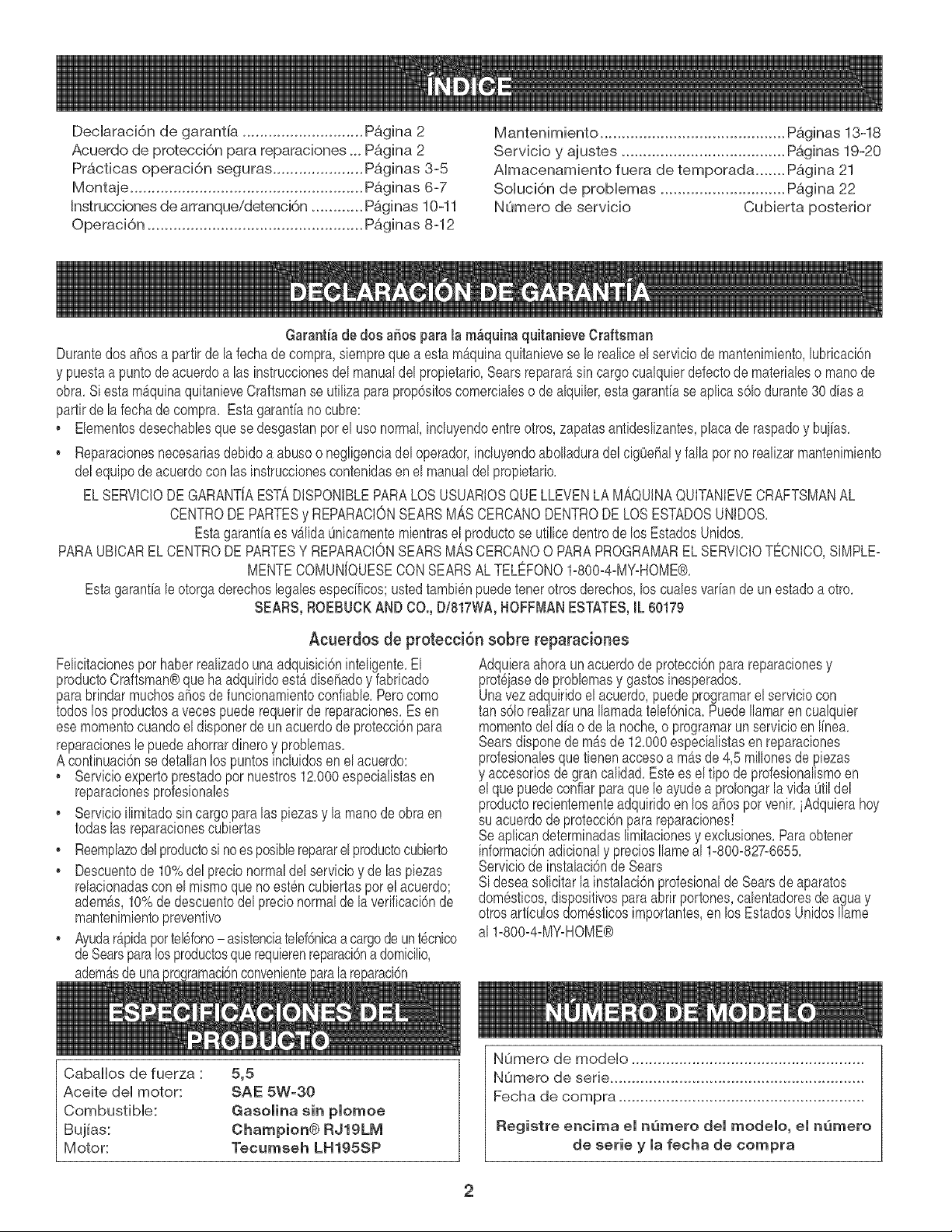
1.KEEPAWAYFROMROTATINGIMPELLER
ANDAUGER.CONTACTWITHIMPELLEROR
AUGERCANAMPUTATEHANDSANDFEET,
2. USECLEAN-OUTTOOLTO UNCLOG
DISCHARGECHUTE.
3. DISENGAGECLUTCHLEVERS,STOPENGINE,
ANDREMAINBEHINDHANDLESUNTILALL
MOVINGPARTSHAVESTOPPEDBEFORE
UNCLOGGINGORSERVICINGMACHINE,
4. TO AVOIDTHROWNOBJECTSINJURIES,
NEVERDIRECTDISCHARGEATBYSTANDERS.
USEEXTRACAUTIONWHENOPERATINGON
GRAVELSURFACES.
5. READOPERATOR'SMANUAL.
LEAN-OUT TOOL I1__
This symbol points out
importantsafety instructions
which, if not followed,could
endangerthe personal safety
and/or propertyof yourself
and others. Readand follow
all instructionsin this manual
beforeattemptingto operate
this machine.Failureto com-
plywith these instructions
mayresult in personalinjury.
When you see this symbol.
HEED ITS WARNING!
Your ResponsibUity
Restrictthe use of this
power machine to persons
who read, understandand
follow the warnings and
instructions in this manual
and on the machine.
f
J
Hayunaherramientade Umpiezade)canal a)ustadaa )a parte
superiorde lacaia de )a barrenacon un pasadorde ensamblado,
La herramientaest_disehadapara)impiare)hie)oy )anievedel
montaiedeuncanal,Esteproductose suietamedianteunauni6n
decable en )a fb,brica,Corte )a uni6nde cable antesde operar)a
m_quinaquitanieve,
_ DVERTENCIA: Never use your hands
to e(ear a nunea use sus manes para
liberar un montaje de canal tapado.
Apague el motor y permanezea detr_s de
las manijas hasta que todas las partes
mSviles se hayan detenido antes de
utilizar ta herramienta de limpieza para
limpiar el montaje del eana.
3
ADVERTENCIA:elescapedelmotordeesteproducto,algunosdesuscomponentesy algunoscom-
ponentesdelvehiculocontienenoemitenproductosquimicosqueelestadodeCaliforniaconsideraque
puedenproducircancer,defectosdenacimientouotrosproblemasreproductivos.
PELIGRO:EstamaquinaestadiseSadaparaserutilizadarespetandolasreglasdeseguridadcontenidasenestemanual
AIigualqueconcualquierripedeequipoel6ctrico,undescuidooerrordepartedeloperadorpuedeproducirlesiones
graves.Estam_.quinaescapazdeamputarmanesy piesy dearrojarobjetoscongranfuerza.Denorespetarlasinstruco
clonesdeseguridadsiguientessepuedenproducirlesionesgravesolamuerte.
ADVERTENCIA:estesimboloindicainstruccionesdeseguridadimportantesquedenoseguirse,se
podriaponerenpeligrola seguridadpersonaly/olapropiedadsuyay deterceros.Leay sigatodaslas
instruccionesenestemanualantesdeiniciarlaoperaci6ndeestamaquina.Encasodenoseguirestas
instruccionespodriaprovocarlesionespersonales.CuandoyeaestesimboloSlGALAADVERTENOIA
Suresponsabilidad:estamaquinael6ctricas61opuedenusarlalaspersonasquelean,comprendany respetenlasad-
vertenciase instruccionesqueaparecenenestemanualy enlamaquina.
Preparativos
1. Inspeccioneminuciosamenteel areadondeutilizaraelequipo.Saquetodos
losfelpudos,peri6dicos,trineos,tablas,cablesy otrosobjetosextrafloscon
los quepodr[atropezaro que podrianser arrojadosporla barrena/ motor.
2. Paraprotegerselos ojosutilice siempreanteojoso antiparrasde
seguridadmientrasopera lamb,quinao mientrasla ajustao repara.Los
objetos arrojadosque rebotanpuedenlesionargravementelavista.
3. Nooperela maquinasinla vestimentaadecuadaparaestaral aire libreen
invierno.No utilicealhajas,bufandaslargasu otras prendassueltasque
podr[anenredarseen las partesmoviles.Utilice un calzadoespecialpara
superficiesresbaladizas.
4. Useun prolongadory untomacorrientede tres cables con conexiona
tierra paratodas las unidadescon motoresde encendidoelectrico.
5. Ajuste laalturade la caja del tomacorrientepara limpiarla grava o las
superficiescon piedrastrituradas.
6. Desengranetodas laspalancasde controlantes de arrancarel motor.
7. Nuncaintenterealizarajustesmientrasel motorestaen marchaexcepto
en loscasos especfficamenterecomendadosen el manualdel operador.
8. Dejequeel motory la maquinaseadaptena latemperaturaexteriorantes
de cornenzara sacarla nieve.
9. Paraevitarlesionespersonalesodaflosmaterialesseasumamentecuidadosoal
manipularlagasolina.Lagasolinaesaltamenteidlamabley susvaporespuedencausar
expiosiones.Sepuedelesionargravementesiderramagasolinasobt9ustedosobrela
ropayaquesepuedept_nderfuego.Laveselapic4y cambiesederopadeinmediato.
a. Utilices61orecipientespara gasolinaautorizados.
b. Apaguetodosloscigarrillos,cigarros,pipasy otrasfuentesde combusti6n.
c. Nuncacarguecombustibleen la m;Jquinaen un espaciocerrado.
d. Nuncasaque latapa del gas niagreguecombustiblemientrasel motor
estacaliente o en marcha.
e. Dejeque el motorse enfr[epor Io menos dos minutosantesde volvera
cargar combustible.
f. Nuncarecargueeltanque de combustible.Lleneeltanque no m;Js
de 1/2 pulgadapor debajo de la basedel cuello del filtro paradejar
espaciopara la dilataci6ndel combustible.
g. Vuelvaa colocar latapa de lagasolinay ajL_stelabien.
h. Limpiela gasolinaderramadasobre el motory el equipo.Trasladela
m;Jquinaa otra zona. Espere5 minutesantesde encenderel motor.
Nuncaalmacenela m;Jquinao el recipientede combustibleen un
espaciocerradodondehayafuego, chispaso luz piloto(per ejemplo,
hornos,calentadoresde agua, calefactores,secadoresde ropa,etc.).
Dejequela maquinase enfrie per Iomenos 5 minutesantes de
guardarla.
Capacitaci6n
1. Lea,entienday cumplatodaslas instruccionesincluidasen la maquinay
en los manualesantes de montarlay utilizarla.Guardeeste manualen un
lugarseguroparaconsultasfuturasy regulares,as[ comopara solicitar
repuestos.
2. Familiaricesecon todos loscontrolesy sufuncionamientoapropiado.Sepa
c6modetenerla maquinay c6modesengranarloscontrolesrapidamente.
3. Nopermitanuncaque losniflos menoresde 14 aflos utilicenesta maquina.
Los nifios de 14 afios y masmayoresdebenleery comprenderlasinstruc-
cionesdefuncionamientoy las reglasde seguridadcontenidasen este
manual,y tambi6ndebenser capacitadosy estar supervisadosporunode
lospadres.
4. Nuncapermitaque losadultosutilicenesta maquinasin recibirantesla
instrucci6napropiada.
5. Los objetosarrojadosperla maquinapuedenproducirlesionesgraves.
Planifiqueel patr6nen el queva a ir arrojandonieveparaevitarque la
descargade materialse realicehacialos caminos,los observadores,etc.
6. Mantengaa losobservadores,ayudantes,mascotasy niflos per Iomenos a
75 pies de la m;Jquinamientrasla mismaestaen funcionamiento.Detenga
la maquinasi alguienentraen la zona.
7. Seaprecavidopara evitarpatinarseo caerseespecialmentecuandoopera
la maquinaen reversa.
4
Operaci6n
1. No pongalasmanes o los piescerca de las piezasrotatorias,en la caja
de la barrena/ motoro en el montajedel canalde descarga.El contacto
con las piezas rotatoriaspuedeproducirla amputaci6nde manosy pies.
2. La palanca de controlde la barrena/ motores un dispositivode seguri-
dad. Nuncapase poralto sufuncionamiento.Dehacerlola operaci6nde
la maquinaes riesgosay puedeocasionarlesiones.
3. Laspalancasde controldebenfuncionarbienenambasdireccionesy
regresarautomaticamentea Isposici6nde desengranecuandose lassuelta.
4. Nuncaoperelamaquinasifaltaunmontajedelcanalo sielmismoest;Jdafiado.
Mantengatodoslosdispositivosdeseguridadensulugaryenfuncionamiento.
5. Nuncaenciendaun motoren espacioscerradoso en unazonacon poca
ventilaci6n.Elescapedel motorcontienemon6xidode carbono,ungas
inodoroy letak
6. No utilicela m;Jquinabajo la influenciadel alcoholo lasdrogas.
7. Elsilenciadory el motorse calientany puedenproducir quemaduras.No
lostoque.
8. Seasumamenteprecavidocuandooperela m_.quinasobre una superficie
con grava o cuandola cruce. Mantengasealerta pot si se presentan
peligrosocultoso transito.
9. Tengacuidado cuandocambiede direcci6n o cuandooperela m;Jquina
en pendientes.
10.Planifiqueel patr6nen el que va a ir arrojandonieveparaevitar que
la descargade materialse produzcahacia lasventanas,las pare@s,
los autom6viles,etc.y evitar as[ posiblesdaflos materialeso lesiones
producidasper los rebotes.
11.Nuncadirija la descargahacialos niflos, losobservadoresy lasmascotas
ni deje que nadiese pare delantede la m;Jquina.
12.No sobrecarguela capacidadde la maquinatratandode sacarla nieve
muyrapidamente.
13.Nunca opereestam;Jquinasin buenavisibilidado iluminaci6n.Siempre
debe estarsegurode queesta bien afirmadoy sostengabien las manijas.
Carnine,nuncacorra.
14.Corte lacorrientea la barrena/ motorcuandotransporte lam;Jquinao
cuandola mismano esta en uso.
15.Nunca operela maquinaa altavelocidad de desplazamientosobre
superficiesresbaladizas.Mirehacia abajoy haciaatr;Jsy tenga cuidado
cuandovayamarchaatras.
16.Si la m;Jquinacomenzaraavibrar de maneraanormal,detengael motor,
desconecteel cable de la bujia y p6ngalade maneraque hagsmass
contrael motor.Inspeccionela maquinaminuciosamenteparaversiesta
daflada.Reparetodos los dafiosantes de encendery operarla maquina.
17.Desengranetodas laspalancasde control y detengael motorantesde
dejar la posici6nde operaci6n(detr;_sde las manijas).Esperea que la
barrens/ motorse detengapor completoantes de destaparel montajedel
canalo realizarajustese inspecciones.
18.Nunca pongalas manesenlas aberturasde descargao de recolecci6n.
Utilice siemprela herramientade limpiezaque se adjuntapara destapar
la aberturade descarga.Nodestapeel montajedelcanal mientrasel
motorest4 en funcionamiento.Antes de destaparlo,apagueel motory
permanezcadetrasde las manijashastaquetodas las partesm6vilesse
hayandetenido.
19.Use s61ounionesy accesoriosaprobadosper elfabricante (perejemplo,
pesaspars las rue@s, cadenaspara los neum;Jticos,cabinas,etc.).
20.Si se presentansituacionesque no estanprevistasen estemanual,sea
cuidadosoy useel senti@ comOn.Contactecon su centrode servicio
Sears paraobtenerayuda.
Mantenimiento y alrnacenamiento
1. Nuncamanipulelosdispositivosde seguridaddemaneraimprudente.
Controleperiodicamenteque funcionende forms adecuada.RemRasea
las seccionesde mantenimientoy ajustede estemanual.
2. Antesde realizarlalimpieza,repararo revisarla m_.quina,desengrane
todas las palancasde controly detengael motor.Esperea que la barrena
/ motorse detengapercompleto.Desconecteelcable de la buj[ay
p6ngalode maneraque hagamasacontra el motorparsevitar quese
enciendade maneraaccidental.
3. Controlefrecuentementequetodos los pernosy tornillosesten bien
ajustadosparscomprobarquela m;Jquinaseencuentraen condiciones
segurasde funcionamiento.Asimismo,realiceuna inspeccionvisual de la
m;_quinapars controlarsi la mismaestadafiada.
4. Nocambiela configuraci6ndel reguladordel motorni aceleredemasiado
el mismo. Elreguladorcontrola lavelocidadm;_ximasegura de operaci6n
del motor.
5. Lasplacasde raspadoy laszapatasantideslizantesqueseusanconlamaquina
quitanievesedesgastany sedaflan.Parsprotegersuseguridad,verifique
fl_cuentementetodosloscomponentesy t_empl;_celoss61oconpartesdelos
fabricantesdeequiposoriginales(OEM)."Lautilizaci6ndepiezasquenocumplan
conlasespecificacionesdeequiposoriginalespodriatenercomoresuttadoun
rendimientoincorrecto,y adema.sla seguridadpodrfaestarcomprometida"
6. Reviselos controlesperi6dicamentepars verificarque engraneny desen-
granen adecuadamentey ajL_stelossi esnecesario.Consultela secci6n
de ajustesen estemanualdel operadorpara obtenerinstrucciones.
7. Mantengao reemplacelas etiquetasde seguridad e instruccionessegOn
sea necesario.
8. Respetelas normasreferentesa ladisposici6ncorrectsy las reglamenta-
clonessobre gas, combustible,etc. paraprotegerel medioambiente.
9. Antesde almacenarla m;Jquinaenci6ndalaunos minutosparasacar la
nieveque hayaquedadoen la mismay paraevitaras[ que secongelela
barrena/ motor.
10.Nuncaalmacenela maquinao el recipientede combustibleen un espacio
cerradodonde hayafuego,chispaso luzpiloto como porejemplo,
calentadoresde agua,hornos,secadoresde ropa,etc.
11.Consultesiempreel manualdefuncionamientoparaconocer lasinstruc-
clonesadecuadaspara el almacenamientofuerade temporada.
No modifique el motor
Parsevitarlesionesgraveso la muerte,no modifiqueelmotorbajoninguna
circunstancia.Si cambialaconfiguraci6ndel reguladorel motorpuededescon-
trolarsey operara velocidadesinseguras.Nuncacambielaconfiguraci6nde
fabricsdel reguladordel motor.
Aviso referido a emisiones
Losmotoresqueestancertificadosy cumplencon las regulacionesde emisio-
nesfederalesEPAy de Californiapara SORE(EquiposSmall Off RoadEquip-
ment)estancertificadospara operarcon gasolinacomOnsinplomoy pueden
incluirlossiguientessistemasde controlde emisiones:Modificaci6nde motor
(EM)y catalizadorde tresvias (TWC)siesta equipadode esa manera.
CaJcoman_a de identificaci6n de! motor
Estacalcomaniaindicael nOmerodel modelodel motor,las especificacionesy
lafechade fabricaci6n.Porfavor,mirela calcomaniaen el motorde su equipo
y registreesa informaci6npara referenciafutura.
Lacalcomaniade identificaci6ndel motortambi6nincluyeespecificaciones
sobre el periodode vida 0til del motorrelacionadocon las emisiones.Este
periodoest;_relacionadocon lavida 0tilen conformidadcon lasemisiones
seg0n IocertificadoporEPAy/o CARB.Parahallarla especificaci6ndel
periododevida Qtildel motor,por favorlea lacalcomaniadel motory ub.ique
laletra(entre comillas)entrelaspalabrasModeradoy Periodode Vida Util.
Conecteunade lassiguientesletrascon la letra impressen su calcomania.
Porejemplo,a los modelosHMSK80 se los designacomo:
"C"-- 250horas
"B"-- 500 horas
"A"-- 1000horas
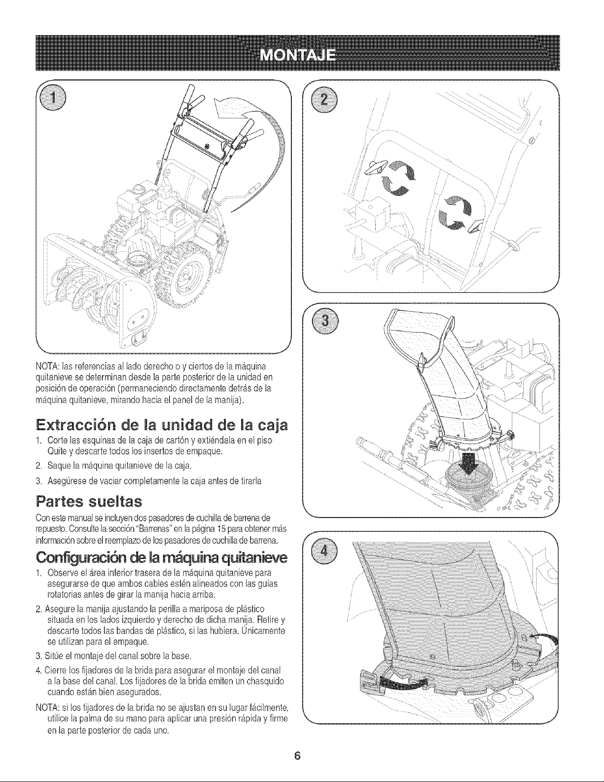
NOTA:las referenciasal ladoderechoo y ciertosde lamb,quina
quitanievesedeterminandesdela parteposteriorde la unidaden
posici6ndeoperaci6n(permaneciendodirectamentedetrAsde la
m_quinaquitanieve,mirandohaciael panelde la maniia),
Extracci6n de la unidad de la caja
1, Corte lasesquinasde lacaiade cart6ny exti6ndaIaen el piso
Quitey descartetodos los insertosde empaque,
2, Saquela m_quinaquitanievede la caia,
3, AsegOresede vaciarcompIetamentela cajaantesde tirarIa
Partes sueltas
ConestemanualseincIuyendospasadoresde cuchillade barrenade
repuesto,ConsuItela secci6n"Barrenas"enlapb,gina15paraobtenermb,s
informacbnsobreelreempIazode lospasadoresdecuchiIIadebarrena,
Configuracidn de la m quina qu n ve
1, Observeel Areainferiortraserade lamb,quinaquitanievepara
asegurarsede queamboscablesestenalineadoscon lasguhs
rotatoriasantes de girar [a maniiahaciaarriba,
2, Asegure[a manijaajustando[aperi[[aa mariposade p[_stico
situadaenlos [adosizquierdoy derechode dichaman!ja.Retirey
descartetodos las bandasde pIAstico,si las hubiera,Unicamente
se utiIizanparael empaque,
3, SitOeel montaiede[ canalsobre[abase,
4, Cierrelosfiiadoresde [abridaparaasegurarel montajedel canal
a [abase de[canal. Losfiiadoresde [a bridaemitenunchasquido
cuandoestb,n bien asegurados,
NOTA:si los fiiadoresde [abrida no se aiustanen su [ugarf_cilmente,
utilicelapalmade su manopara apIicarunapresi6nr_piday firme
enla parteposteriorde cada uno,
\
6
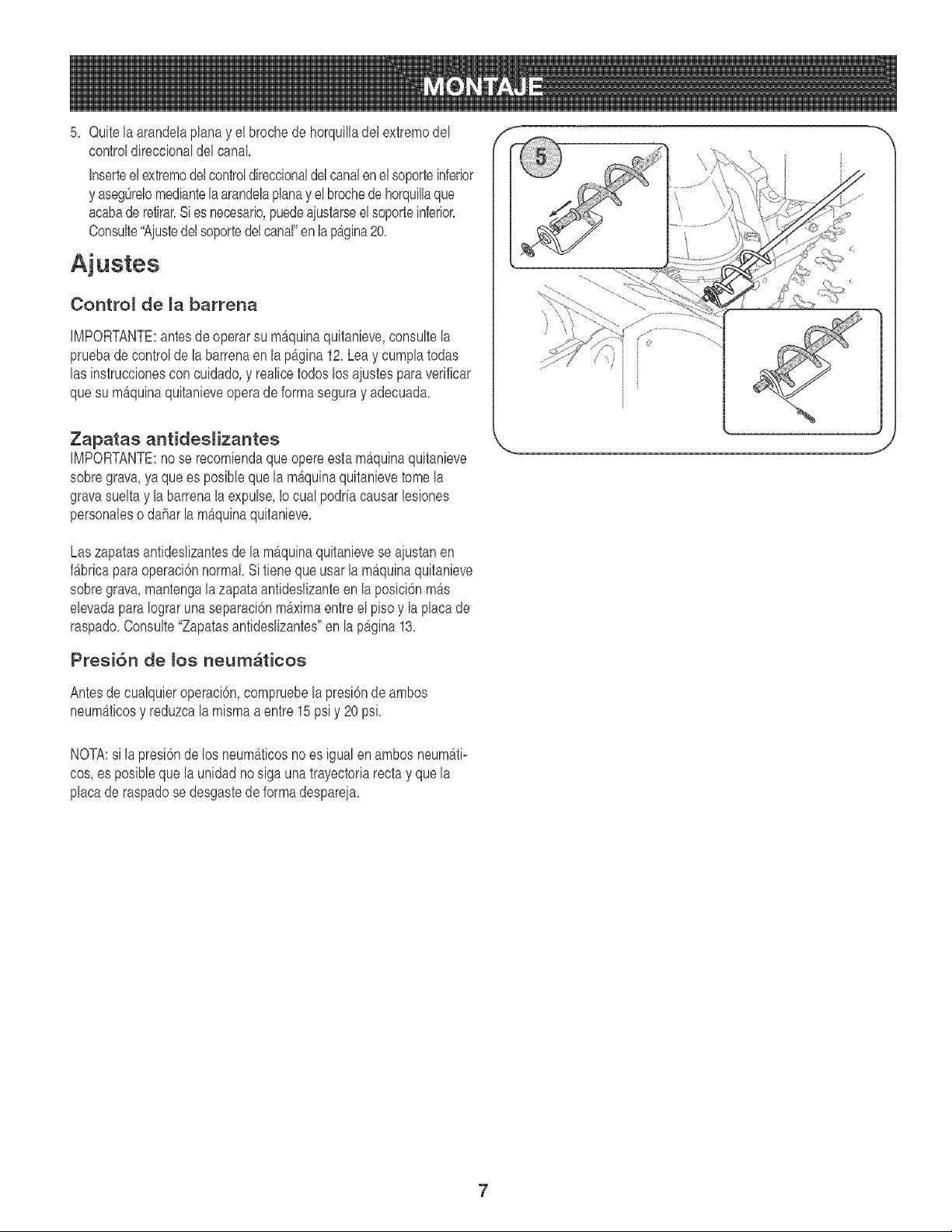
5. Quitela arandelaplanay el brochede horquilladel extremodel
controldireccionaldelcanal
Inserteel extremodelcontroldireccionaldelcanalenel soporteinferior
y asegOrelomediantelaarandelaplanay el brochedehorquillaque
acabade retirar.Sies necesario,puedeaiustarseel soporteinferior.
Consulte"Aiustedelsoportedelcanal"enlap_,gina20.
Ajustes
Contro_ de _a barrena
IMPORTANTE:antesde operarsu mAquinaquitanieve,consultela
pruebadecontroldela barrenaen la p_.gina12.Lea y cumplatodas
las instruccionescon cuidado,y realicetodoslos aiustesparaverificar
quesu m_,quinaquitanieveoperadeformaseguray adecuada.
Zapatas antideslizantes
IMPORTANTE:no se recomiendaque opereesta m_quinaquitanieve
sobregrava,yaque es posibleque la m_quinaquitanievetomela
gravasuelta y la barrenala expulse,Iocualpodr[acausarlesiones
personaleso daharla m_,quinaquitanieve.
Las zapatasantideslizantesdela mAquinaquitanievese aiustanen
f_bricaparaoperaci6nnormal Si tienequeusar la m_quinaquitanieve
sobregrava,mantengala zapataantideslizanteen la posici6nm_s
elevadapara Iograruna separaci6nm_ximaentreel pisoy la placade
raspado.Consulte"Zapatasantideslizantes"en lap_gina13.
Presi6n de _os neum_ticos
Antesde cualquieroperaci6n,compruebelapresi6nde ambos
neum_ticosy reduzcalamismaa entre 15psiy 20 psi.
NOTA:si lapresi6nde los neum&ticosno es igualen ambosneumAti-
cos,es posibleque la unidadno siga unatrayectoriarectay quela
placade raspadose desgastede formadespareia.
7
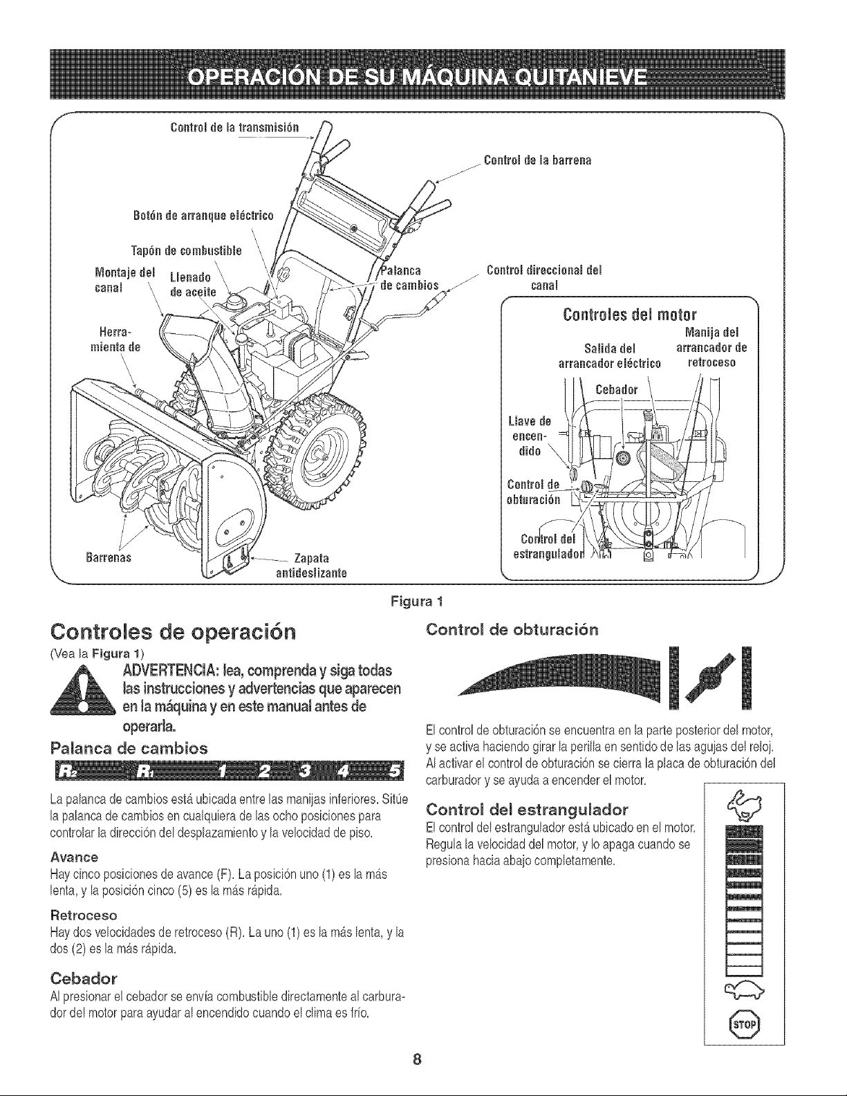
Contro es de operaci6n
(Vea la Figura 1)
ADVERTENCIA:lea,comFenda y siga todas
lasinstruccionesy advertencias que apareeen
en la m_quinayen este manual antes de
operaria.
Pa_anca de cambios
Lapalancade cambiosestb_ubicadaentrelas maniiasinferiores,SitOe
lapalancade cambiosen cualquierade las ocho posicionespara
controlarladirecci6ndel desplazamientoy lavelocidaddepiso,
Avarice
Haycincoposicionesde avance(F), Laposici6nuno(1)es lam_s
lenta,y la posici6ncinco(5) es la m_s r_pida,
Retroceso
Haydos velocidadesde retroceso(R), La uno (1) es la mAslenta,y la
dos (2) es la m_s r_pida,
Cebador
AI presionarel cebadorse envfacombustibledirectamenteal carbura-
dordel motorparaayudaral encendidocuandoelclimaes frio,
Contro_ de obturaci6n
Elcontroldeobturaci6nse encuentraen la parteposteriordel motor,
y se activahaciendogirar la perillaen sentidode lasaguiasdel reloi,
AI activarel controlde obturacbnse cierralaplaca de obturaci6ndel
carburadory se ayudaaencenderel motor,
Contro_ del estrangu_ador
ElcontroldelestranguladorestAubicadoen el motor,
Regulala velocidaddelmotor,y Ioapaga cuandose
presionahaciaabaio completamente,
©
m
l
m
8
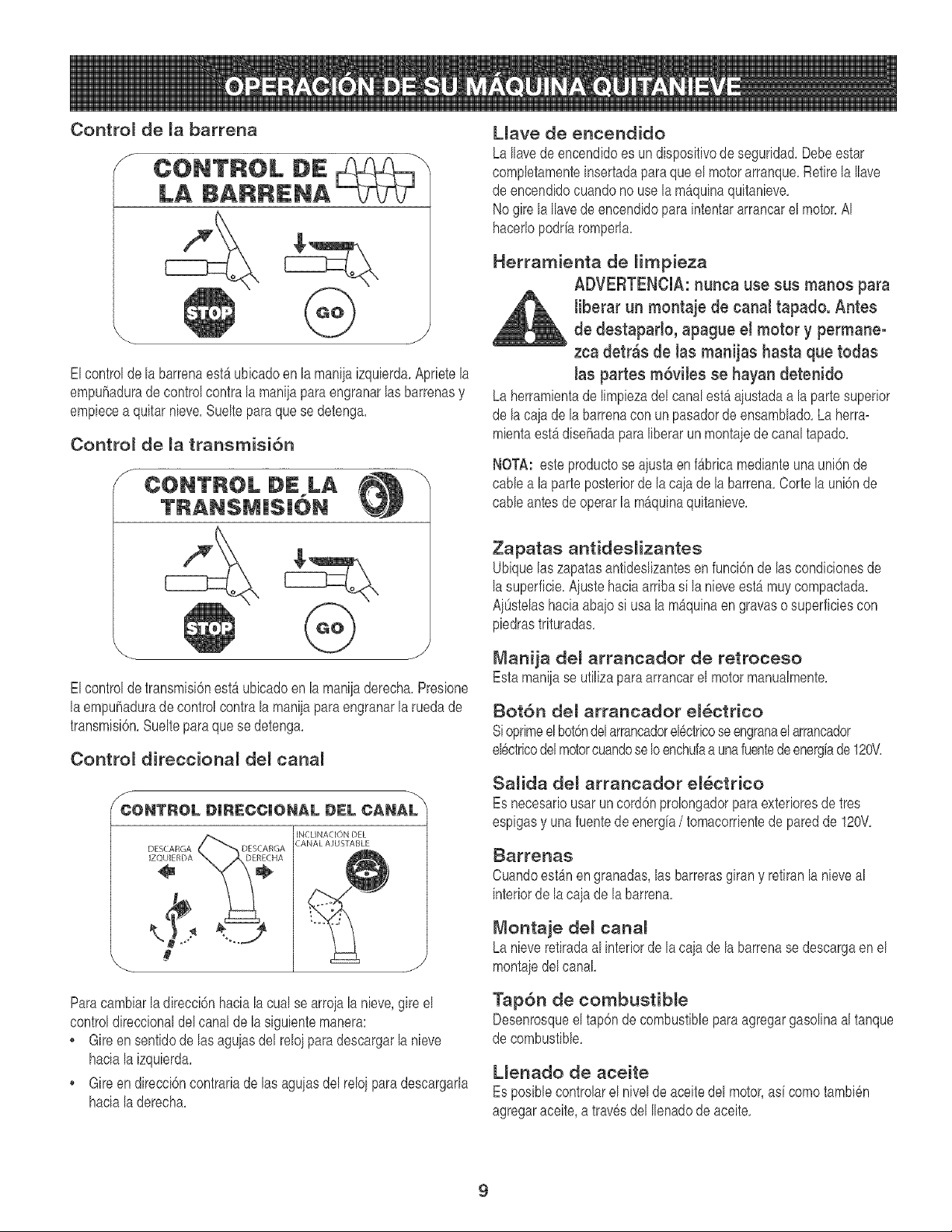
Contro_ de la barrena
Elcontroldela barrenaestAubicadoen la maniiaizquierda,Aprietela
empuhadurade controlcontra la maniiaparaengranarlas barrenasy
empiecea quitar nieve,Sueltepara que se detenga,
Contro_ de la transmisi6n
f CONTROL DE LA
S
Elcontroldetransmisi6nestb,ubicadoen lamaniiaderecha,Presione
laempuhadurade controlcontra la manijapara engranarla rueda de
transmisi6n,Suelteparaquese detenga,
Contro_ direccional del canal
\
DESCARGA
]ZQUIEfiDA
Paracambiarla direcci6nhaciala cual se arroiala nieve,gireel
controldireccionaldelcanal de la siguientemanera:
• Gireen sentidode lasaguiasdel reloiparadescargarlanieve
haciala izquierda,
• Gireen direcci6ncontrariade las aguiasdel reloiparadescargarla
haciala derecha,
LJave de encendido
LaIlavedeencendidoes undispositivode seguridad,Debeestar
completamenteinsertadaparaqueel motorarranque,Retirela Ilave
de encendidocuandono usela m_quinaquitanieve,
Nogire la Ilavedeencendidopara intentararrancarel motor,AI
hacerlopodrh romperla,
Herramienta de Hmpieza
ADVERTENCIA: nunca use sus manos para
Jiberar un montaje de canal tapado. Antes
de destaparlo, apague el motor y permane°
zca detr_s de Jas manijas hasta que todas
Jas partes m6viles se hayan detenido
Laherramientade limpiezadel canalestAaiustadaa la partesuperior
de lacaia de labarrenacon un pasadorde ensamblado,La herra-
mientaestAdisehadapara liberar un montaiede canaltapado,
NOTA: esteproductose aiusta enfb,brica medianteunauni6nde
cablea la parte posteriordela cajade labarrena,Corte la uni6nde
cableantes de operar la mAquinaquitanieve,
Zapatas antidesHzantes
Ubiquelas zapatasantideslizantesen funci6n de las condicionesde
lasuperficie,Ajustehaciaarriba si la nieveestAmuycompactada,
AiOstelashaciaabaiosi usa lam_quinaen gravaso superficiescon
piedrastrituradas,
Manija del arrancador de retroceso
Estamaniiase utilizaparaarrancarel motormanualmente,
Bot6n del arrancador e_ctrico
si oprimeelbot6ndelarrancadorel6ctricoseengranaelarrancador
el6ctricodelmotorcuandoseIoenchufaaunafuentedeenergiade120V,
Salida de[ arrancador ei_ctrico
Esnecesariousaruncord6nprolongadorparaexterioresdetres
espigasy unafuentedeenerg[a/ tomacorrientede paredde 120V,
_arret_as
Cuandoest_n en granadas,las barrerasgiran y retiranla nieveal
interiorde la caiade la barrena,
Montaje deJ canal
Lanieveretiradaal interiorde lacaia de la barrenase descargaen el
montajedelcanal
Tap6n de combustible
Desenrosqueel tap6n decombustibleparaagregargasolinaal tanque
de combustible,
L{enado de aceite
Esposiblecontrolarel nivelde aceitedel motor,as[ comotambi6n
agregaraceite,a trav6sdel Ilenadode aceite,
9
Antes de encender el motor
ADVERTENCIA:lea, comprenda y siga todas las
instrucciones y advertencias que aparecenen la
m_quina y en este manual antes de operarla.
Aceite
El motorse env[6con aceiteen el motor,Controleel nivelde aceite
antesde cadaoperaci6nparaasegurarsede quehayaaceite
suficienteenel motor,Paraobtenerm_s [nstrucciones,remitasea los
pasosqueaparecenen lapb,g[na 17,
1, Saquela varilladel nivelde aceite del orific[ode Ilenadodeaceite,
2, Controley compruebeque elnivelde aceiteest6hastaarr[baen la
marcaFULLde la varilladel niveldel aceite,
3, S[el n[velde aceiteno IlegahastaFULL,v[ertaaceite de motor
nuevo(5W=30,con unaclasificaci6nminimade %/%) lentamente
a travesde la abertura,Vuelvaa colocar la varilladel nivelace[te
enel Ilenadodeace[tey controlenuevamenteel n[velde ace[te,
Gasolina
ADVERTENCIA:tenga extremo cuidado cuando ma=
nipule gasolina. La gasolina es altamente inflamable
y sue vapores pueden cauear explosiones. Nunca
agregue combustible a la m_quina en interioreso
mientras el motor est_ caliente o en funcionamiento.
Apague los cigarrillos, cigarros, pipas y otras
fuentes de combusti6n.
, AImacenela gasolinaenun recipienteaprobadolimp[oy coloquela
tapaen el recipiente,
• Aseg0resedequeelrecipientedesdeelcualviertelagasolinaest6
limp[oy noest6oxidadon[contaminadoconotrasparticulasextrahas,
NOTA:dentrodelaaperturaparaIlenadode combustblepuedeencontrarse
unatapaguardapolvosdeplb,stico,Retirey descarte,s[ la hubiera,
Llenesiempreel tanquede combustibleal aire librey useun
embudoo pico paraevitar derramamientos,
• Lleneeltanquedecombustiblecongasolinasinplomo,limpiayfresca,
• NuncaIlenecompletamenteeltanque,Lleneeltanquehasta1/2pulgpor
debaiodeltope,deiandoas[espacioparaladilatacbndelcombustible,
, Aseg0resedelimpiarel combustibleque se hayaderramadoantes
dearrancarel motor,
Encendido de[ motor
1, Conecteel cablede la buifaa la misma,Compruebeque el lazo
de metaldelextremode la bujiaeste bienajustado(dentrode la
mangade goma)sobrelapunta met_licade la buiia,
2, Aseg0resede que el controlde labarrenay el controlde la
transmisi6nestenen posici6ndesengranada(sinpresionar),
3, Muevael controldel estranguladora la posici6nFAST(rb,pido),
Insertela Ilavede encend[doen la ranura,Aseg0resede que entre
a presi6nensu lugar,No [ntenteg[rarlaIlave,
NOTA:el motornopuedearrancars[ la Ilavenoest_completamente
[nsertadaen el [nterruptorde encendido,
Arrancador e!_ctrico
1, Determines[elcableadodesuhogaresunsistemadetrescab#sconectadoa
t_e_a,Consulteconunelectidstamatriculadosinoestb,seguro,
ADVERTENCIA:el arrancador el_ctrico
opcional est_ equipado con un cable de
alimentaci6n y un enchufe de tres terminales
conectados a tierra y est_ diseSado para opo
erar con corriente dom_stica de 120 vottios,
Debe set utilizado con un recept_culo de tres
terminales correctamente conectado a tierra
en todo momento para evitar la posibitidad
de descargas el_ctricas,
Si su sistema de cableado dom_stico no es
un sistema de tres terminales con cone×i6n
a tierra, no utitice este motor el_ctrico bajo
ningSn tipo de condiciones.
Si su sistema de cableado dom_stico es
un sistema con cone×i6n a tierra, pero no
cuenta con un recept_culo de tres terminao
les, no utilice et arrancador el_ctrico de su
m_quina quitanieve,
Siga todas tas instrucciones cuidadosao
mente para operar el arrancador el_ctrico,
s[ cuentacon un recept_culode tres term[hales,sigalos s[gu[entes
pasos:
1, Conecteel prolongadora lasalidasituadaen lasuperficiedel
motor,Conecteel otro extremodel prolongadoren un receptb,culo
de CAcon conexi6na tierrade tresterminalesde 120voltios,en
un _reabienventilada,
2, G[reel controlde obturacbn a pos[ci6nde obturac[6nFULL(para
encendidocon el motoren fr[o),
NOTA:s[ el motorya estb,caliente,ubiqueelcontroldelobturadoren
posici6nOFFenlugarde FULL,
3, Presioneel cebadordoso tres vecespara arrancarel motoren
fr[o,asegurb,ndosede cubrirel orific[ode ventilaci6nsituadoen el
centrodelcebadorcuandoest6pres[onando,
NOTA:NO UTILICEel cebadorparareiniciarun motorcalientetras
unadetenci6nbreve,
4, Pres[oneel bot6ndel arrancadorparaarrancarel motor,
5, Unavezencendidoel motor,suelteel bot6ndelarrancador,
6, Mientrasse calientael motor,girelentamenteel controldelobtu-
radora posici6nOFF(apagado),S[ el motorfalla,vuelvaa girar
r&p[damenteel obturadora pos[ci6nFULLy luego,lentamente,a
posici6nOFFde nuevo,
7, Cuandodesconecteel prolongador,desenchufesiempreel extremo
delreceptb,culodetresterminalesen el tomacorrientede paredantes
dedesenchufarel extremoopuestodela m_qu[naqu[tan[eve,
10
Arrancador de retroceso
1, Gire el controlde obturaei6na posici6nde obturaci6nFULL
(encendidocon el motoren if[o),
NOTA:Is[ el motorya estAcaliente,ubique el controldel obturadoren
posici6nOFFen lugardeFULL,
2, Presioneel cebadordoso tres vecesparaarrancarel motoren
if[o, asegur_ndosede eubrirel orifie[ode ventilaei6nsituadoenel
centrodelcebadorcuandoest6presionando,
NOTA:NO UTILICEel cebadorparareiniciarunmotorcalbnte tras
unadetenci6nbreve,
NOTA:tal vezsea necesar[ouncebadoadicionals[la temperaturaes
inferiora 15° Fahrenheit,
3, Tomela maniiadelarrancadorde retrocesoy tire de lacuerda
baciaafuerabntamente,Enel momentoen elquese baga
bvementem_s dificil tirarde la euerda,permitaque la misma
retrocedalentamente,
4, Tirede la maniiadel arrancadorcon unmovimientofirmey r@ido,
Nosuelte la maniian[permitaquese desenganche,Mantengala
maniiadel arraneadorfirmementesuietay permitaque lacuerda
retroeedalentamente,
5, Mientrasse calientael motor,girebntamenteel control del obtu-
radora posici6nOFF(apagado),Siel motorfalla, vuelvaa girar
r@idamenteel obturadora posici6nFULLy luego,bntamente,a
posiei6nOFFde nuevo,
NOTA:permitaque el motorse calbnte duranteunosminutostras el
arranque,El motorno desarrollar_todasu potenciabastaque aleance
temperaturasoperativas,
Detenci6n motor
Deieencendidoel motordurantealgunosminutosantes de detenerlo
parapermitirque seseque lahumedadenel mismo,
Paraayudara prevenirunposibleeongelamientodel arraneador,
procedade lasiguientemanera:
Arrancador el_ctrico
1, Conecteel prolongadora la salidadelarrancadorel@tricoenel
motory luegoal tomaeorrientede CAde 120voltios,
2, Conel motorfuncionando,presioneel bot6ndelarraneadory deie
girarelarrancadordurantevariossegundos,El ruido realizadopor
elarraneadores normal El arraneadordel motornoestb,dahado,
3, Cuandodeseoneeteelprolongador,desenehufesiempreel extremo
delrecept_eulodetresterminabsen el tomaeorrientedeparedantes
dedesencbufarel extremoopuestode lam_quinaquitanieve,
4, Muevael control del estranguladora laposiei6nSTOP(parada),
5, Retirela Ilavedeencendidoy gu_rdelaenun lugarseguro,
6, Limpiela nievey la humedaddel _reaalrededordelmotor,as[
comotambi6nenel _rea(y alrededorde esta) del interiorde los
controbs de la transmisi6ny de la barrena,Asimismo,engancbey
suelteamboscontrolesvariasveces,
Arrancador de retroceso
1, Con el motoren funcionamiento,tirecon fuerzade la sogadelar-
rancadortres o cuatrovecesde maneracontinuay seguida,AItirar
de la sogadelarrancadorse oir_ un fuerte sonidode traqueteo,el
cual no daha al motor,
2, Muevael controldelestranguladora la posici6nSTOP(parada),
3, Retirela Ilavede encendidoy gu_rdelaen unlugarseguro,
4, Limpb la nbve y la humedaddel £reaalrededordelmotor,ad
comotambi6nenel _rea(y alrededorde esta) del interiorde los
controbs de la transmisi6ny de la barrena,Asimismo,enganchey
suelteamboscontrolesvariasveces,
Herramienta de impieza del canal
Laherrambntade limpbzadel canalest_ajustadaconvenbntemente
a laparteposteriorde la cajade labarrenacon un pasadorde ensam-
blado,S[ se acumulannbve y hieloenel canaldedescargadurante
laoperaci6n,procedacomo se indba a continuaci6nparalimpiarde
manerasegurael montajedelcanaly la aberturadel canal:
1, Suelteel controlde labarrenay el controlde la transmisi6n,
2, Paradetenerel motorsaquela Ilavede encendido,
3, Saquela herrambntadelimpiezadelpasadorquela a]ustaa la
parteposteriorde lacaia de labarrena,
ADVERTENCIA: el sitenciador, el motor y
las zonas que toe rodean pueden cabntarse
y eausar quemaduras. No tos toque.
4, Useel extremocon formade paladela herrambntade limpbza
paradesplazary recogerla nbve y el hMo que se formaroncerca
del conjuntodel canal,
5, Vuelvaa ajustar la berrambntade limpiezaalpasadorde ensam-
bladoubbadoen laparte posteriorde lacaja de labarrena,[nserte
de nuevola Ilavede encendidoy encbnda elmotorde la m_quina
quitanbve,
6, Paradoen laposbi6ndeloperador(detr_sdelam_quinaquitanbve),
engraneelcontroldelabarrenaduranteunossegundosparaeliminar
lanbveo el hieloque hayanquedadoenelconiuntodelcanal,
Procedimiento para engranar
transmisi6n
1, Con elcontroldelestranguladorenposici6nr@ida (dibujode
unconejo),muevalapalancadecambiosa unade las cinco
poslcionesde avarice(F) o de las dosposlclonesde reversa
(R),Sebccionela velocidadadecuadaparael estadode la nbve
existentey una velocidadcon laquese sbnta c6modo,
11
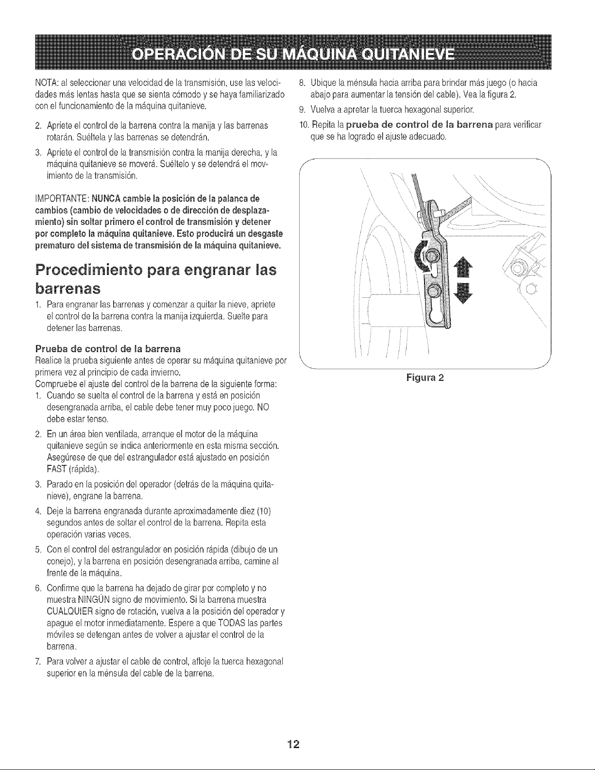
NOTA:al seleccionarunavelocidadde la transmisi6n,use lasveloci-
dadesm_s lentashastaquese sientac6modoy se hayafamiliarizado
conel funcionamientode la m_quinaquitanieve.
2. Aprieteel controlde la barrenacontrala maniiay las barrenas
rotarAn.Su61telay las barrenasse detendrAn.
3. Aprieteel controlde latransmisi6ncontralamaniiaderecha,y la
mAquinaquitanievese moverA.Su61teloy se detendrAel mov-
imientodela transmisi6n.
IMPORTANTE:NUNCAcambie la posici6n de la palanea de
eambios (eambio de velocidades o de direeci6n de desplaza-
miento) sin soltar primero el control de transmisi6n y detener
pot cornpleto la rn_quinaquitanieve. Esto producir_ un desgaste
prematuro del sisterna de transrnisi6n de la rn_quinaquitanieve.
Procedimiento para engranar
barrenas
1. Paraengranarlas barrenasy comenzara quitarla nieve,apriete
el controldela barrenacontrala maniiaizquierda.Sueltepara
detenerlas barrenas.
Prueba de controJ de ta barrena
Realicelapruebasiguienteantesde operarsu m_quinaquitanievepor
primeravez al principiode cadainvierno.
Compruebeel ajustedel controlde labarrenade lasiguienteforma:
1. Cuandose sueltael controlde la barrenay estb,en posici6n
desengranadaarriba,elcable debetener muy pocoiuego.NO
debeestartense.
2. En un Areabienvenfilada,arranqueel motorde la mAquina
quitanievesegOnse indicaanteriormenteen estamismasecci6n.
AsegOresedequedelestranguladorestAaiustadoen posici6n
FAST(r_pida).
3. Paradeen la posici6ndel operador(detr_sde la m_quinaquita-
nieve),engranelabarrena.
4. Deiela barrenaengranadaduranteaproximadamentediez(10)
segundosantesde soltarel controlde la barrena.Repitaesta
operaci6nvarias veces.
5. Conel controldelestranguladoren posici6nrApida(dibuiode un
coneio),y la barrenaen posici6ndesengranadaarriba,camineal
frentede lamAquina.
6. Confirmeque la barrenaha deiadode girar per completey no
muestraNINGONsignode movimiento.Si labarrenamuestra
CUALQUIERsigno derotaci6n,vuelvaa la posici6ndel operadory
apagueelmotorinmediatamente.Esperea que TODASlaspartes
m6vilesse detenganantesde volvera aiustar el control de la
barrena.
7. Paravolvera aiustarel cablede control,afioiela tuercahexagonal
superioren lam6nsuladelcablede labarrena.
8. Ubiquela mensulahaciaarribaparabrindarmAsiuego(o hacia
abaioparaaumentarlatensi6ndelcable).Vealafigura2.
9. Vuelvaaapretarla tuerca hexagonalsuperior.
10.Repitala prueba de controJ de ta barrena paraverificar
quese haIogradoel ajuste adecuado.
S
Figura 2
12
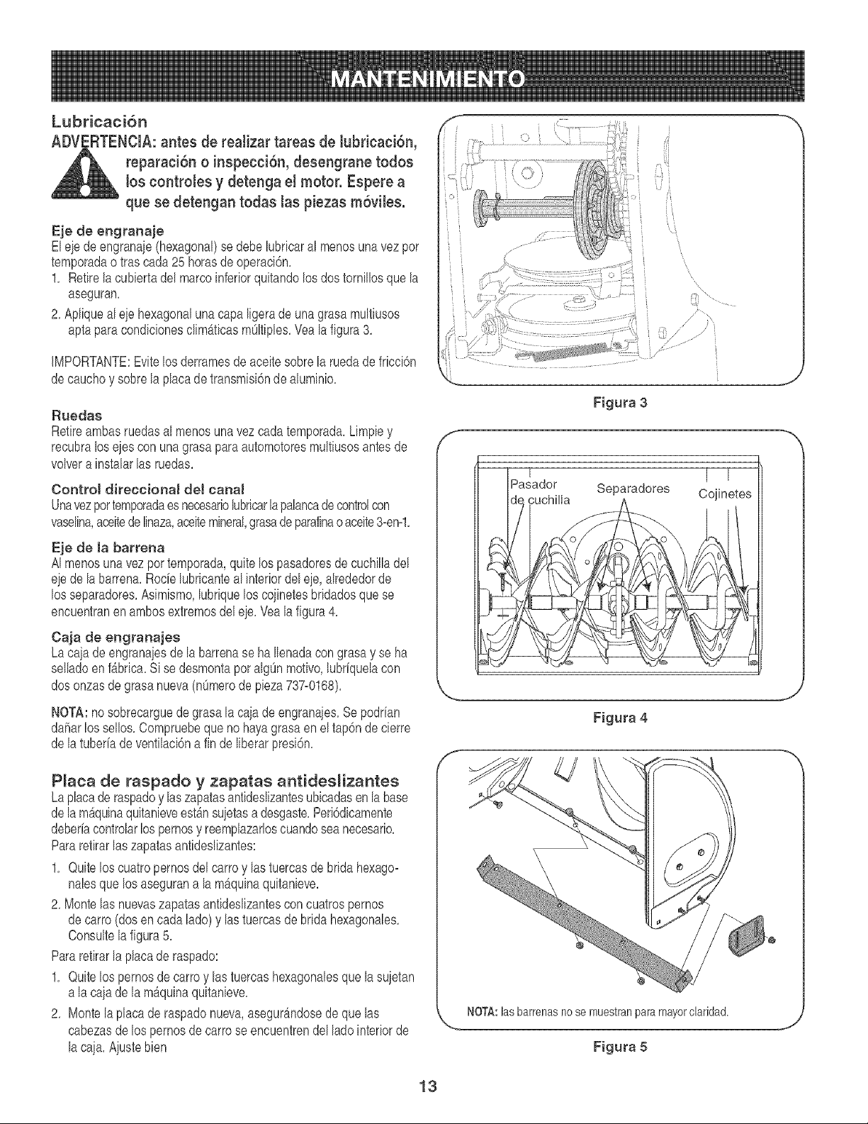
Lubricaci6n
ADVI RTENCiA: antes de reatizar tareas de Jubricaci6n,
reparaci6n o inspecci6n, desengrane tedes
los controles y detenga et motor. Espere a
que se detengan tedas las piezas rnSviles.
Eje de engranaje
Eleie deengranaie(hexagonal)se debelubricaral menosunavezpor
temporadaotras cada25 horasde operaci6n.
1. Retirela cubiertadel marcoinferiorquitandolos dostornillosque la
aseguran.
2. Apliqueal eie hexagonalunacapa ligerade unagrasamultiusos
aptapara condicionesclim_ticasmOltiples.Vea la figura 3.
IMPORTANTE:Evitelos derramesde aceitesobrela ruedade fricci6n
decauchoy sobrela placade transmisi6nde aluminio.
Ruedas
Retireambasruedasal menosuna vez cadatemporada.Limpiey
recubraloseies conunagrasapara automotoresmultiusosantes de
voKfera instalarlas ruedas.
Control direccional del canal
Unavezportemporadaesnecesariolubricarlapalancadecontrolcon
vaselina,aceitede linaza,aceitemineral,grasadeparafinaoaceite3-en-1.
Eje de la barrena
AI menosunavez por temporada,quitelos pasadoresdecuchilladel
eiede labarrena.Rode lubricanteal interiordeleie,alrededorde
los separadores.Asimismo,lubriquelos coiinetesbridadosquese
encuentranenambosextremosdel eie.Vea la figura4.
Caja de engranajes
Laca}ade engranaiesdela barrenase ha Ilenadacongrasay se ha
selladoen f_brica.Si se desmontapor algOnmofivo,lubrfquelacon
dosonzas de grasanueva(nOmerode pieza737-0168).
NOTA:no sobrecarguedegrasala caiade engranaies.Sepodrfan
daharlos sellos.Compruebequenohayagrasaenel tap6nde cierre
de latuberfadeventilaci6na finde liberarpresi6n.
Plata de raspado y zapatas antides_izantes
Laplacade raspadoy laszapatasantideslizantesubicadasen la base
dela m_quinaquitanieveestb,nsuietasa desgaste.Peri6dicamente
deberhcontrolarlos pernosy reemplazarloscuandoseanecesario.
Pararetirarlas zapatasantideslizantes:
1. Quitelos cuatropernosdel carroy lastuercasdebridahexago-
halesque los asegurana la m&quinaquitanieve.
2. Montelas nuevaszapatasantideslizantesconcuatrospernos
decarro (dosencada lado) y las tuercasde brida hexagonales.
Consultela figura5.
Pararetirarla placade raspado:
1. Quitelos pernosde carroy lastuercashexagonalesquelasuietan
a lacaia de lam_quinaquitanieve.
2. Montela placade raspadonueva,asegurb,ndosede quelas
cabezasde lospernosdecarrose encuentrendel ladointeriorde
la caja.Ajustebien
Si 'i
'i
\
\
7
Fig_Jra 3
S
Figura 4
k,,,_ NOTA:lasbarrenasno se muestranpara mayorclaridad.
.Y
Figura 5
13
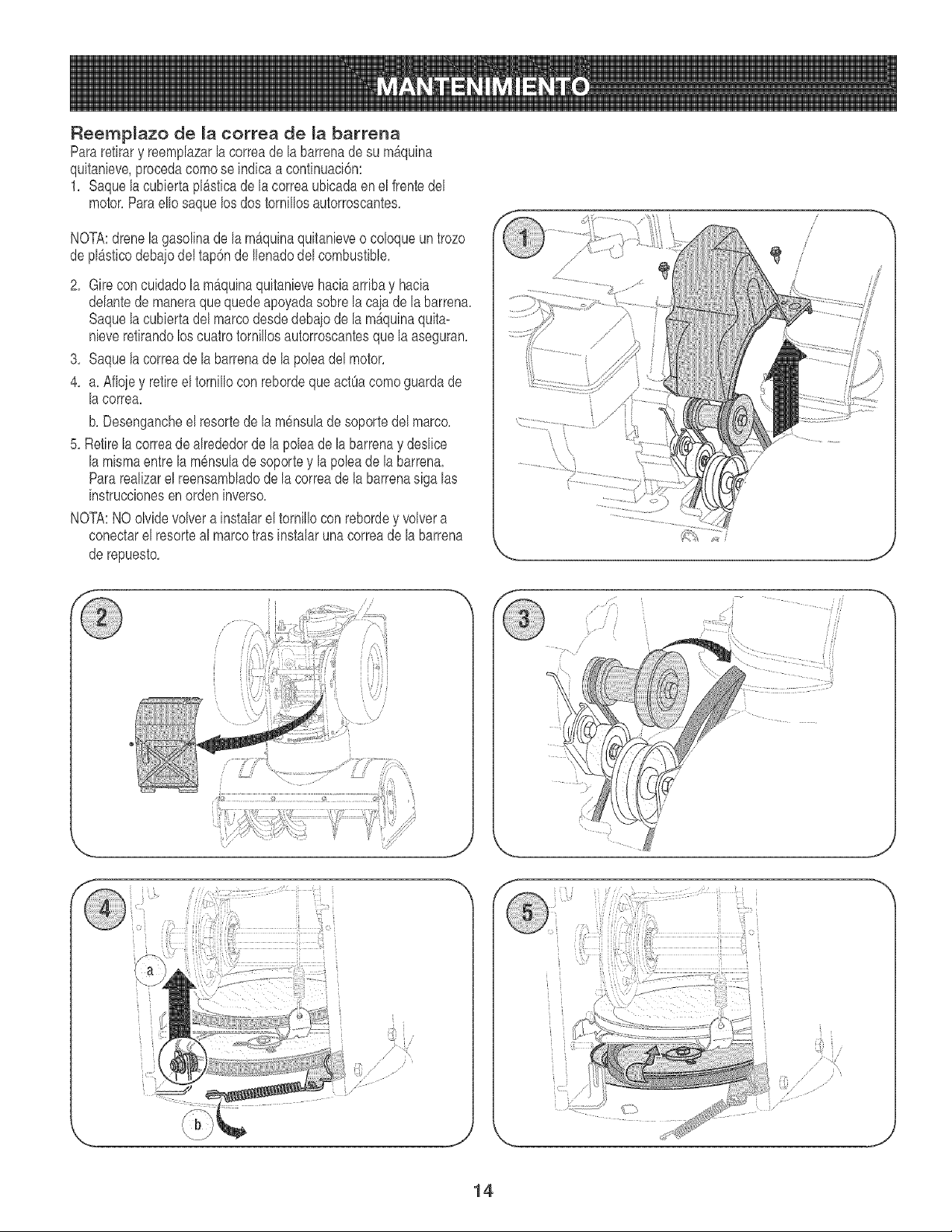
Reemplazo de la correa de la barrena
Pararetirary reemplazarla correadela barrenade su m_quina
quitanieve,procedacomose indicaa continuaci6n:
1, Saquela cubiertapl_sticade lacorrea ubicadaen el frentedel
motor,Paraello saquelosdos tornillosautorroscantes,
NOTA:drenela gasolinade la mb,quinaquitanieveo coloqueun trozo
de plAsticodebaiodeltap6nde Ilenadodelcombustible,
2, Gire concuidadolamb,quinaquitanievehaciaarribay hacia
delantede maneraquequedeapoyadasobrela cajade la barrena,
Saquela cubiertadelmarcodesdedebaiode la mAquinaquita-
nieveretirandoloscuatrotornillosautorroscantesque la aseguran,
3, Saquela correade labarrenade la )oleadel motor,
4, a, Afloiey retireel tornillocon rebordequeactOacomoguardade
la correa,
b, Desengancheel resortede la m6nsulade soportedel marco,
5, Retirela correade alrededorde la poleade labarrenay deslice
la mismaentre la mensulade soportey lapoleadela barrena,
Pararealizarel reensambladode la correade labarrenasigalas
instruccionesen orden inverso,
NOTA:NOolvidevolverainstalarel tornillocon rebordey volvera
conectarel resorteal marcotras instalaruna correadela barrena
de repuesto,
i
/
/
/
/
J \
J
J
14
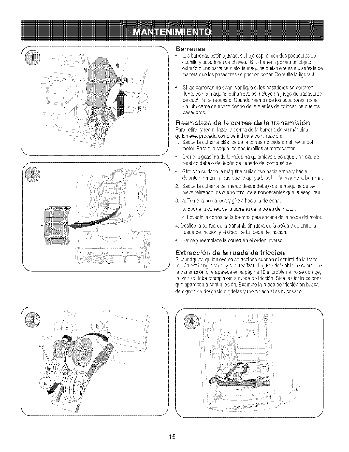
J
_arrenas
Las barrenasest_naiustadasal eieespiralcon dospasadoresde
cuchillay pasadoresde chaveta.Si labarrenagolpeaunobieto
extrahoo unabarradehielo,la ma'quinaquitanieveestb,disehadade
maneraque lospasadoressepuedencortar.Consultelafigura4.
Silas barrenasno giran,verifiquesi los pasadoressecortaron.
Juntocon la m_quinaquitanievese incluyeuniuegodepasadores
de cuchillade repuesto.Cuandoreemplacelos pasadores,rode
unlubricantedeaceitedentrodel ejeantesde colocarlos nuevos
pasadores.
Reempmazo de la correa de _a transmisi6n
Pararetirary reemplazarlacorreade la barrenadesu mAquina
quitanieve,procedacomose indicaa continuaci6n:
1. Saque la cubiertaplSsticade lacorreaubicadaen elfrentedel
motor.Paraello saquelos dostornillosautorroscantes.
. Drenela gasolinade lamb,quinaquitanieveo coloqueun trozo de
plSsticodebaiodel tap6nde Ilenadodelcombustible.
• Girecon cuidadolam_quinaquitanievehaciaarribay hacia
delantede maneraque quedeapoyadasobre lacaia de labarren&
2. Saque la cubiertadel marcodesdedebaiode la mSquinaquita-
nieveretirandolos cuatrotornillosautorroscantesquela aseguran.
3. a. Tomela poleaIocay girela haciala derecha.
b. Saquelacorreade la barrenade la poleadel motor.
c. Levantelacorreadela barrenaparasacarlade la poleadel motor.
4. Deslicela correade la transmisi6nfuerade lapoleay de entrela
ruedadefricci6ny el discodela ruedade fricci6n.
• Retirey reemplacela correaen elordeninverso.
Extracci6n de _a rueda de fricci6n
si la m_quinaquitanievenose accionacuandoel controlde latrans-
misi6nestb,engranado,y si al realizarel aiustedelcane de controlde
latransmisi6nqueapareceen lapSgina19el problemanose corrige,
tal vez se debareemplazarla ruedadefriccbn. Sigalas instrucciones
queaparecena continuaci6n.Examinelaruedadefricci6nen busca
de signosde desgasteo grietasy reemplacesi es necesario
..... 17
f
...._'.i_i_
J
15
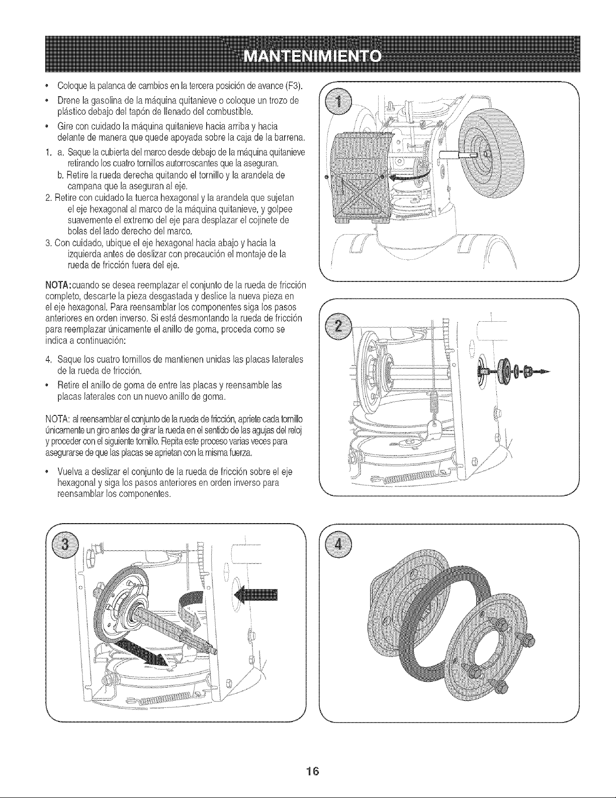
Coloquela palancadecambiosen la terceraposici6nde avance(F3),
, Drenelagasolinade lamb,quinaquitanieveo coloqueuntrozode
pl£sticodebaiodel tap6nde Ilenadodel combustible,
• Gireconcuidadola m_quinaquitanievehaciaarribay hacia
delantede maneraquequedeapoyadasobrela cajade la barrena,
1, a, Saquela cubiertadel marcodesdedebaiodelam£quinaquitanieve
retirandoloscuatrotornillosautorroscantesque la aseguran,
b, Retirela ruedaderechaquitandoeltornilloy la arandelade
campanaque laaseguranaleie,
2, Retirecon cuidadola tuercahexagonaly la arandelaque sujetan
el eiehexagonalal marcode la m_quinaquitanieve,y golpee
suavementeelextremodel ejeparadesplazarel coiinetede
bolasdel ladoderechodel marco,
3, Con cuidado,ubiqueel eiehexagonalhaciaabaioy hacia la
izquierdaantesde deslizarcon precauci6nel montaiede la
ruedade fricci6nfueradeleie,
NOTA:cuandose deseareemplazarel coniuntode la ruedadefricci6n
completo,descartela piezadesgastaday deslice la nuevapiezaen
eleie hexagonal,Parareensamblarlos componentessiga lospasos
anterioresenordeninverso,Si est£ desmontandola ruedadefricci6n
parareemplazarOnicamenteel anillo de goma, procedacomose
indicaa continuaci6n:
4, Saquelos cuatrotornillosde mantienenunidaslas placaslaterales
de laruedadefricci6n,
Retireel anillode gomadeentre las placasy reensamblelas
placaslateralescon unnuevoanillo de goma,
NOTA:al reensambhrelconiuntode laruedadefricci6n,aprietecadatornillo
Onicamenteungiroantesdegirarlaruedaenel sentidode hs aguiasdelreloi
y procederconelsiguientetornillo,Repitaesteprocesovariasvecespara
asegurarsedequelasplacasseaprietanconla mismafuerza,
Vuelvaa deslizarelconjuntodela ruedade fricci6nsobreel eie
hexagonaly siga los pasosanterioresen ordeninversopara
reensamblarlos componentes,
.j
f
J
J \
J
16
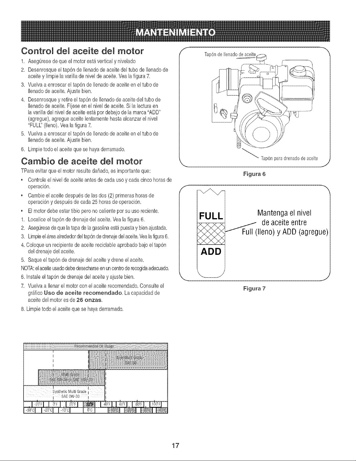
Contro_ de_ aceite tier motor
1, AsegOresede que el motorest_ verticaly nivelado
2, Desenrosqueel tap6nde Ilenadode aceitedel tubode Ilenadode
aeeitey limpielavarillade nivelde aeeite,Veala figura7,
3, Vuelvaa enroscarel tap6nde Ilenadode aceiteen el tubo de
Ilenadode aeeite,Aiustebien,
4, Desenrosquey retireel tap6nde Ilenadodeaceitedeltubode
Ilenadode aceite,Fiieseen el niveldeaceite,Si la lecturaen
la varilladel niveldeaceiteestb,por deba}ode lamarca"ADD"
(agregue),agregueaceite lentamentehastaalcanzarel nivel
"FULl" (lleno),Yea la figura7,
5, Vuelvaa enroscarel tap6nde Ilenadode aceiteen el tubo de
Ilenadode aceite,Aiustebien,
6, Limpietodo el aceitequese hayaderramado,
Cambio de aceite de_ motor
TParaevitar que el motorresultedahado,es importanteque:
• Controleel nivelde aceiteantesde cadauso y cadacinco horasde
operaci6n,
, Cambieel aceitedespu6sde lasdos (2)primerashorasde
operaci6ny despuesde cada25 horasde operaci6n,
, El motordebeestartibio perono calienteporsu uso reciente,
1, Localiceel tap6nde drenaiedelaceite,Veala figura6,
2, AsegOresedeque la tapadelagasolinaestapuestay bienajustada,
3, Limpieel_reaalrededordeltap6nde drenaiedelaceite,Vealafigura6,
4, Coloqueun recipientede aceite reciclableaprobadobaio el tap6n
deldrenaiedelaceite,
5, Saqueel tap6ndedrenaiedelaceitey dreneel aceite,
NOTA:el aceiteusadodebedesecharseen uncentrode recogidaadecuado,
6, Instaleeltap6nde drenaiedel aceitey ajustebien,
7, Vuelvaa Ilenarel motorcon el aceite recomendado,Consulteel
grb,fico Uso de aceite recomendado, La capacidadde
aceitedel motores de 26 onzas,
8, Limpietodoel aceiteque se hayaderramado,
f
f
Tap6nde Ilenadodeaceite
_ Tap6nparadrenadodeaceite
Figura 6
FULL
ADD
Mantenga el nivel
---'''"_Full ( de aceite entre
Ileno) y ADD (agregue)
I
I
Synthetic M[_lti Grade l
i SAE OW-30 I
17

ControR de bujia
Controlelabuiiaanualmenteo cada tO0 horasde operaci6n,
1, Limpieel_reaalrededorde labuiia,
2, Saquee inspeccionela buiia,
3, Cambiela buiiasi laporeelanaest_rotao si loselectrodosest&n:
picados,quemadoso atoradoscon dep6sitos
4, Controleel espaciodelelectrodocon un calibradordeseparacio-
nesy aiustedichoespaeioa 0,030pulg (0,76ram)si es necesario,
Vealafigura8,
5, Vuelvaa instalarla buiiay aiustebien,
NOTA:para el reemplazose debeufilizarunabuiiade resistor,
Contactecon un centro de partesy reparaci6nSearsparaunabuiia
de repuesto,
Carburador
Si creequesu carburadornecesitaunaiuste,consultecon un centro
de partesy reparaci6nSears,El desempeRodelmotorno debeverse
afectadoa altitudesde hasta7,000pies (2,134m), Para operacionesa
mayoraltitud,contactecon uncentrode partesy reparaci6nSears,
Ve_ocidad de_ motor
ADVERTENCIA:para evitarlesionesgraveso la muerte,
NO modifiqueel motorbaio ningunacircunstancia,Si
cambialaconfiguraci6ndel regulador,el motory el
equipopuedenoperara velocidadesinseguras,NUNCA
cambielaconfiguraci6nde fb,bricadel reguladordel mo-
tor,Hacerfuncionarel motora unavelocidadsuperiora
la establecidaen f_bricaes peligroso,
f
2
1. Espacio de 0,030 pulg (0,76 ram)
2. Electrodo
3. Porcelana
Figura 8
18

Ajuste de[ control de [a barrena
Consultela pruebade controlde la barrenaen [ap_gina12para
ajustardichocontrol,
Ajuste de control de [a transmis[Sn
ADVERTENC[A: NUNCA intente reaJizar
_IL ning_n tipo de ajuste mientras e[ motor est_
encendido, excepto si se especifica asi en
este manual de[ operador.
Cuandose sueltae[controlde latransmisi6ny est_ enposici6n
desenganchadaardba,el cabledebetener muypocojuego, NOdebe
estartenso,
Compruebeel ajustedelcontroldelatransmisi6nde[asiguienteforma:
1, Cuandosuelteel controlde latransmisi6n,empujesuavemente
la maquinaquitanievehaciadelante,La unidaddeberia avanzar
[ibremente,
2, Engancheel controlde [atransmisi6ne [ntenteempujarsuave-
mentela maquinaquitanievehaciade[ante,Las ruedasnodeben
girar,La unidadno debeavanzarlibremente,
3, Conel controlde la transmisi6nsuetto,muevala palancade cam-
bios haciaatrAsy haciadelanteentrela pos[ci6nR2y [aposici6n
F6 variasveces,No deberiahaberresistenciaen lapalancade
cambios,
4, S[falla cualqu[erade las pruebasanteriores,es necesadoajustar
elcable de la transm[si6n,Procedade la siguientemanera:
5, Afloje[atuerca hexagonalinferiordel soportede[cablede la
transmisi6n,Veala figura9,
6, Ubiquelam6nsulahaciaarribapara brindarm_sjuego (o hacia
abajoparaaumentar[a tensi6ndelcable),
7, Vue[vaa apretar[a tuercahexagonalsuperior,
Ajuste de[ rnontaje del canal
Es posibleajustar la distanciaa la cualse arrojalanievecambiandoe[
angulodel montajedelcanal Parahaeerlo:
1, Detengael motorquitandola I[avede encendidoy aflojela peril[a
a mariposade plasticoque se encuentraen ellado izquierdodel
montajede[ canal
2, Gire el canal haciaarribao haciaabajoantesdeapretarla peritlaa
mariposa,Vea [a figura10,
f
Figura 9
J
Figura 10
J
19
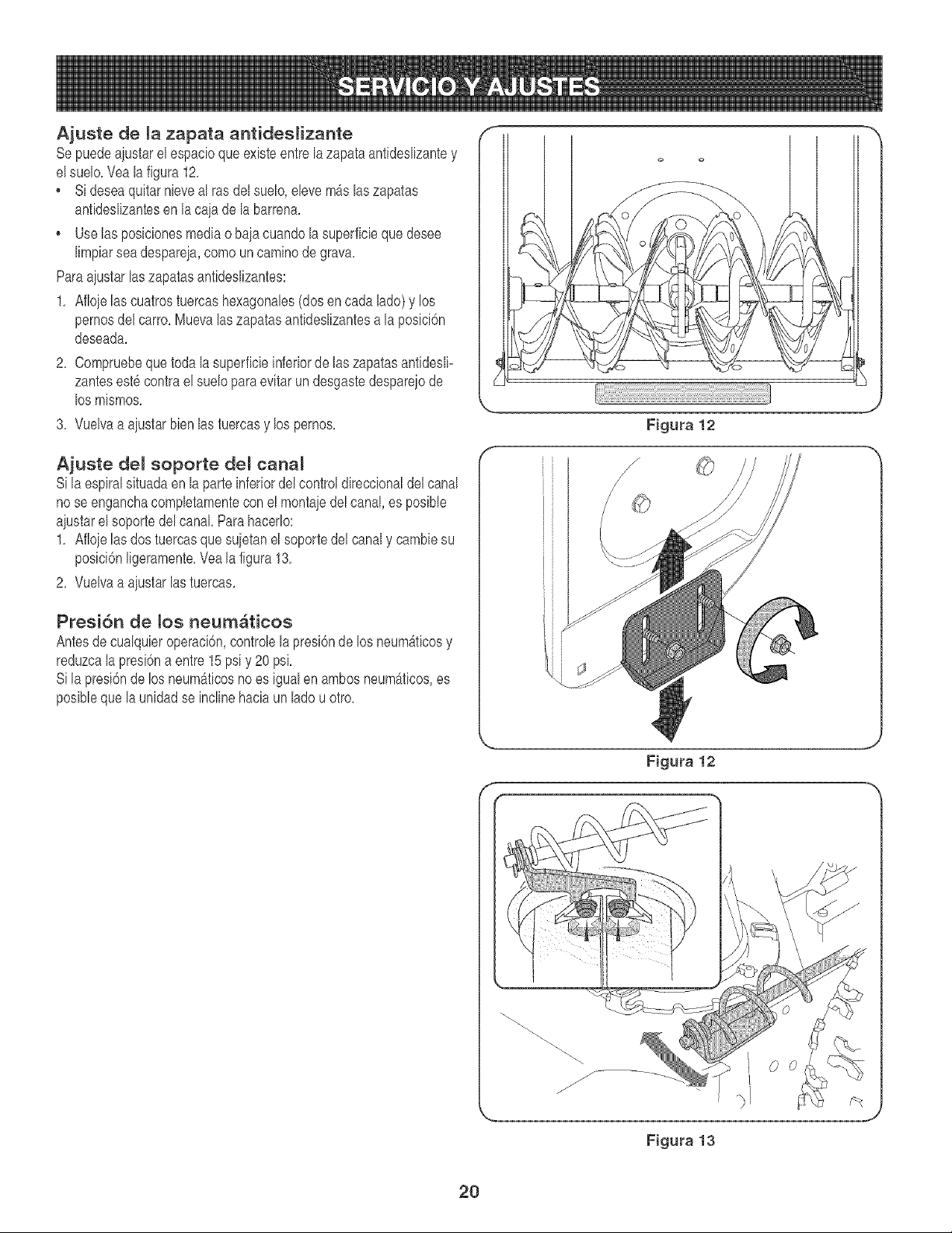
Ajuste de la zapata antidestizante
Sepuedeaiustarelespacioqueexisteentrelazapataantideslizantey
elsuelo,Yealafigura 12,
Sideseaquitarnieveal ras delsuelo,elevem_s laszapatas
antideslizantesen la caiade la barren&
Uselas posicionesmediao baia cuandolasuperficiequedesee
limpiarsea despareia,como un caminodegrava,
Paraaiustarlaszapatasantideslizantes:
1, Afloielas cuatrostuercashexagonales(dosen cada lado)y los
pernosdel carro,Muevalas zapatasantideslizantesa la posici6n
deseada,
2, Compruebeque todala superficieinferiorde laszapatasantidesli=
zantesest6 contra el sueloparaevitarundesgastedesparejode
los mismos,
3, Vuelvaa aiustarbien las tuercasy los pernos,
Ajuste de_ soporte del cana_
Si laespiralsituadaen laparte inferiordel controldireccionaldel canal
nose enganchacompletamenteconel montaiedel canal,es posible
aiustarel soportedelcanal,Parahacerlo:
1, Afloielas dostuercasque suietanel soportedel canaly cambiesu
posici6nligeramente,Vea la figura13,
2, Vuelvaa aiustarlas tuercas,
Presi6n de los neum;_ticos
Antesde cualquieroperaci6n,controlelapresi6nde los neum&ticosy
reduzcalapresi6na entre 15psi y 20psi,
Si lapresi6ndelos neum_ticosnoes igual en ambos neum_ticos,es
posibleque launidadse inclinehaciaun ladeuotro,
Figura 12
./
/
Figura 12
_ J
Fig_Jra 13
2O
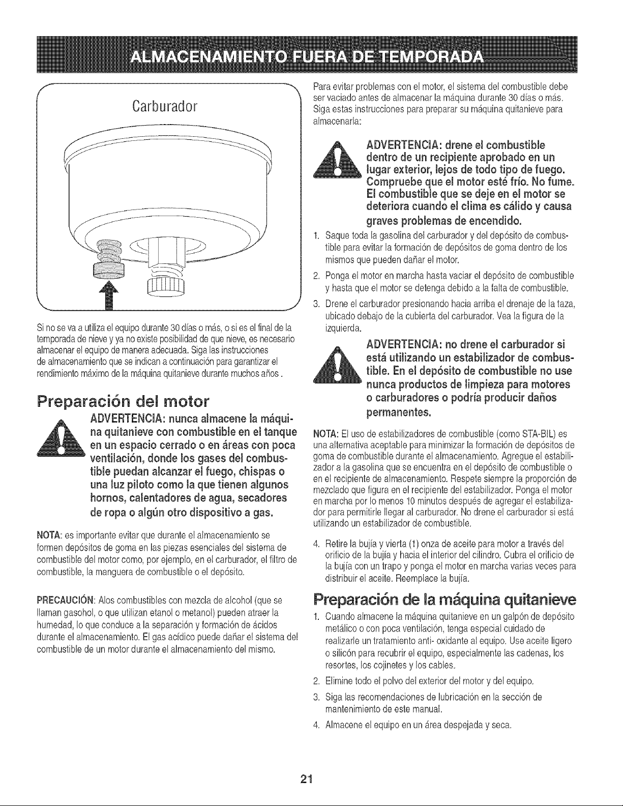
f ---,,
Carburador
Sinosevaa utilizaelequipodurante30 diasomb_s,o si eselfinaldela
temporadadenievey ya noexisteposibilidadde quenieve,es necesario
almacenarelequipodemaneraadecuada,Sigalas instrucciones
dealmacenamientoquese indicana continuaci6nparagarantizarel
rendimientom_ximode la m_,quinaquitanievedurantemuchosahos,
Preparaci6n motor
ADVERTENCIA: nunca aJmacene la m_qui-
na quitanieve con combustiMe en el tanque
en un espaeio eerrado o en _reas con poea
ventiJaei6n, donde los gases deJ eombus°
tible puedan aleanzar eJ fuego, chispas o
una luz piloto como Ja que tienen algunos
homos, catentadores de agua, seeadores
de ropa o aJgSnotto dispositivo a gas.
NOTA:es importanteevitarqueduranteel almacenamientose
formendep6sitosde gomaen laspiezasesencialesdel sistemade
combustibledel motorcomo,poreiemplo,en elcarburador,elfiltrode
combustible,la manguerade combustibleo el dep6sito,
PRECAUCION:AIoscombustiblescon mezclade alcohol(quese
Ilamangasohol,o queufilizanetanolo metanol)puedenatraerla
humedad,Io queconducea la separaci6ny formaci6nde Acidos
duranteel almacenamiento,El gas ac[dicopuededaharel sistemadel
combustiblede un motorduranteel almacenamientodel mismo,
Paraevitarproblemascon el motor,el sistemadel combustibledebe
ser vaciadoantesde almacenarlamb,quinadurante30 dhs o m_s,
Sigaestas instruccionesparaprepararsu m_,quinaquitanievepara
almacenarla:
ADVERTENCIA: drene et combustible
dentro de un reeipiente aprobado en un
lugar exterior, lejos de todo tipo de fuego.
Compruebe que el motor est_ fdo. No fume.
El combustible que se deje en el motor se
deteriora cuando el elima es e_lido y eausa
graves problemas de eneendido.
1, Saquetoda lagasolinadel carburadory deldep6sitodecombus=
fible para evitarla formaci6nde dep6sitosde gomadentrode los
mismosquepuedendaharel motor,
2, Pongael motoren marchahastavaciarel dep6sitode combustible
y hastaqueel motorse detengadebido a lafaltade combustible,
3, Dreneel carburadorpresionandohaciaarriba el drenajede lataza,
ubicadodebajode la cubiertadel carburador,Veala figura de la
izquierda,
ADVERTENCIA: no drene el carburador si
_i st_ utitizando un estabilizador de combus-tible. En e! dep6sito de combustible no use
nunea productos de timpieza para motores
o earburadores o podda produeir daSos
permanentes.
NOTA:El usode estabilizadoresdecombustible(comoSTA=BtL)es
unaalternativaaceptablepara minimizarla formaci6nde dep6sitosde
gomade combustibleduranteelalmacenamiento,Agregueel estabili-
zadora la gasolinaquese encuentraen eldep6sitodecombustibleo
en el recipientede almacenamiento,Respetesiemprela proporci6nde
mezcladoque figuraenel recipientedelestabilizador,Pongael motor
en marchaporIo menos10 minutosdespu6sde agregarel estabiliza-
dor parapermitirleIlegaral carburador,Nodreneel carburadorsi est_
ufilizandounestabilizadorde combustible,
4, Retire la buiia y vierta (1)onza deaceiteparamotora trav6sdel
orificiodela buifay haciael interiordel cilindro,Cubrael orificiode
la bujiacon un trapoy pongael motoren marchavariasveces para
distribuirel aceite,Reemplacelabuiia,
Preparacidn de la m quina quitanieve
1, Cuandoalmacenela m_quinaquitanieveen ungalp6nde dep6sito
met_licoo con pocaventilaci6n,tengaespecialcuidadode
realizarleun tratamientoanti- oxidanteal equipo,Use aceite ligero
o silic6npararecubrirelequipo,especialmentelascadenas,los
resortes,los coiinetesy los cables,
2, Eliminetodoel polvodel exteriordel motory delequipo,
3, Siga las recomendacionesde lubricaci6nen la secci6nde
mantenimientodeestemanual,
4, Almaceneel equipoen un_readespeiaday seca,
21
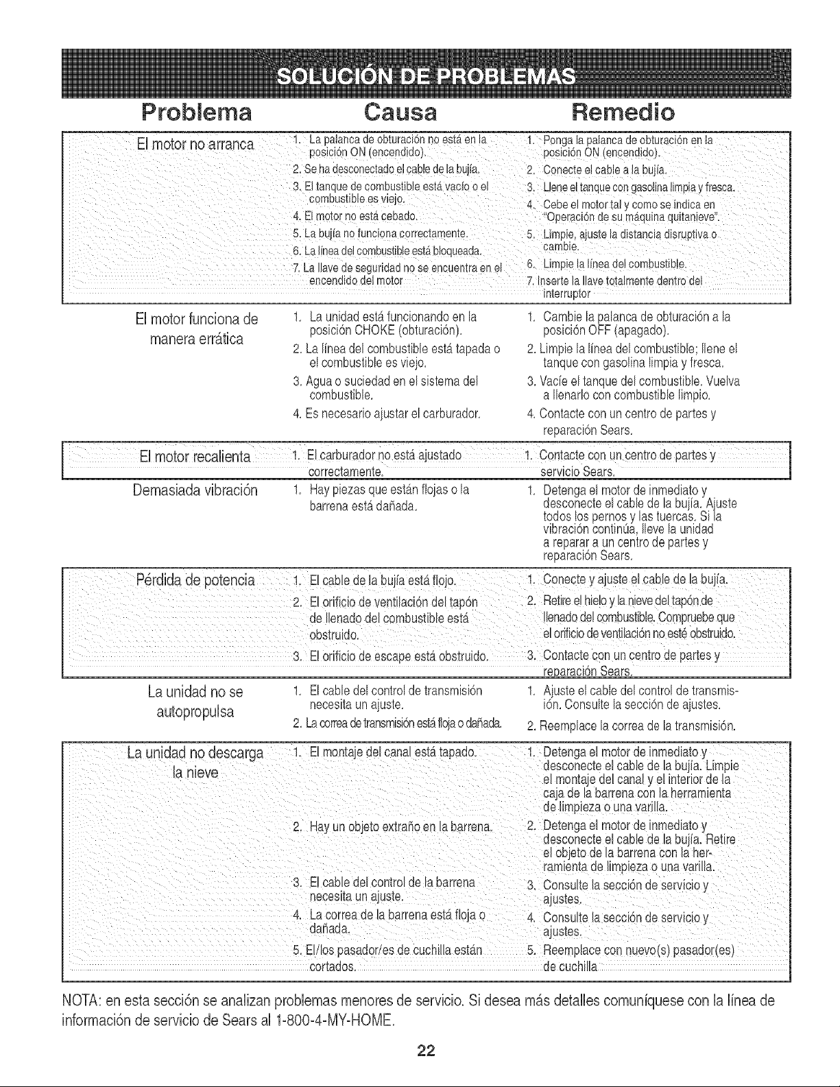
Probiema Causa Remedio
m __ __
E motor no arranoa 1. Lapalancadeobturaci6nnoest6.enla I, Pongalapalancadeobturaci6nenla
posicbnON(encendjdo). posicJ6nON(encendido),
2,SehadesconectadoelCabledeh bujfal 2. Conecteel Cablealabujial
3, E!tanquedeCombustibleest_vacio0el 3. UeneeltanqueCongasolJnalimpiay fresca,
c°mbust_b!eesvae/O' 4. cebee!motorta!y Comese indJcaen
4. ElmotornoestA¢ebado. _'Operaci6ndesumAquinaquitanieve:
5, LabuifanofuncionaCorrectamente, 5. Lirnpie,aiustela disianciadisruptivao
6, LaJheade!Cembust!b!eestAbloqueadal carrlbie_
7, LaIlavedeSeguridadnoSeencuentraen 6, Lirnpie[alineade! combust!b!el
encendidedetmotor 7,InsertelaIlavetetalmentedentrodel
interrupto[
El motor funciona de
manera erratica
1, La unidadestAfuncionandoen la
posici6nCHOKE(obturaci6n),
2, LalineadelcombustibleestAtapadao
el combustiblees vieio,
3, Agua o suciedaden elsistemadel
combustible,
4, Es necesarioajustarel carburador,
1, Cambie la palancade obturacidna la
posici6nOFF(apagado),
2, Limpielalineadelcombustible;Ileneel
tanquecon gasolinalimpiay fresca,
3, Vade el tanquedelcombustible,Vuelva
a Ilenarlocon combustiblelimpio,
4, Contactecon uncentrede partesy
reparaci6nSears,
Demasiada vibraci6n
1, Haypiezasque estb_nfloiaso la
barrenaestb.dahada,
1, Detengael motorde inmediatoy
desconecteel camede la buiia,Aiuste
todos lospernosy las tuercas,Si/a
vibraci6ncontinOa,Ileve la unidad
a reparara un centrede partesy
reparaci6nSears,
3, Eto_ificiode escapeestaobstruido, 3, Contactecon uncentrede partesy
_araei6n Sears,
La unidad no se 1, Elcane delcontrolde transmisidn 1, Aiuste el cane del controlde transmis-
autopropulsa necesitaun aiuste, i6n,Consultela secci6nde aiustes,
2, Lacorreadetransmisidnestaflojaodahada, 2, Reemplacela correade la transmisbn,
cortados, de cuchilla
NOTA: en esta secci6n se analizan problemas menores de servicio. Si desea mas detalles comuniquese con la linea de
informaci6n de servicio de Sears al 1-8004-MY-HOME.
22

iiiiiiiiiiiiiiiiiiiiiiiiii?ii_....
iiiiiiiiiiiiii_,_,'
iiiiiiiiiiiiii
iiiiiiiiiiiiii
iiiiiiiiiiiiii
iiiiiiiiiiiiii
iiiiiiiiiiiiii
iiiiiiiiiiiiii
iiiiiiiiiiiiii
iiiiiiiiiiiiii
iiiiiiiiiiiiii
iiiiiiiiiiiiii
iiiiiiiiiiiiii
iiiiiiiiiiiiii
iiiiiiiiiiiiii
iiiiiiiiiiiiii
iiiiiiiiiiiiii
iiiiiiiiiiiiii
iiiiiiiiiiiiii
iiiiiiiiiiiiii
iiiiiiiiiiiiii
iiiiiiiiiiiiii
iiiiiiiiiiiiii
iiiiiiiiiiiiii
iiiiiiiiiiiiii
iiiiiiiiiiiiii
iiiiiiiiiiiiii
iiiiiiiiiiiiii
iiiiiiiiiiiiii
iiiiiiiiiiiiii
!_i_!jjjjjjjjjjjjjji_i_i
Your Home
For repair-in your home-of all major brand appliances,
lawn and garden equipment, or heating and cooling systems,
nomatterwhomade.. nomatterwho o,dit,
iiiiiiiiiiiiiiiiii
For the replacement parts, accessories and
owner's manuals that you need to do-it-yourself.
iiiiiiiiiiiiiHHi
For Sears professional installation of home appliances
and items like garage door openers and water heaters.
1-800-4-MY-HOME ® (1-800-469-4663)
Call anytime, day or night (U.S.A. and Canada)
www.sears.cor,www.sear .ca
OurHome
For repair of carry-in items like vacuums, lawn equipment,
and electronics, call or go on-line for the location of your nearest
Sears Parts & Repair Center.
1-800-488-1222
Call anytime, day or night (U.S.A. only)
www.sears.corn
To purchase a protection agreement (U.S.A.)
or maintenance agreement (Canada)on i product serviced by Sears:
1 800 827 6655 (U.S.A.) 1 800 361 6665 (Canada)
Pare pedir servicio de reparaciOn Au Canada pour service en frangais:
a domicilio, y para ordenar piezas: 1.800.LE.FOYERMC
1-888-SU-HOGAR SM 1 800 533 6937
(- - _ )
(1-888-784-6427) www.sears.ca
SeO/rS
TM SM
_) Registered Trademark / Trademark / Service Mark of Sears, Roebuck and Co,
TM SM
_3 Marca Registrada / Marca de Fabrica / Marca de Servicio de Sears, Roebuck and Co.
MC MD
Marque de commerce / Marque deposee de Sears, Roebuck and Co. (cbSears, Roebuck and Co.


