Loading ...
Loading ...
Loading ...
5
English
(2) Consider whether the place where the unit will be
installed can support the full weight of the unit, and
reinforce it with boards and beams, etc. if needed
before proceeding with the installation. Also, rein-
force the area to prevent vibration and noise before
installing.
(The installation pitch can be found on the paper
pattern for installation (3), so refer to it when consid-
ering the necessity for reinforcing the location.)
(3) The indoor unit may not be directly installed on the
wall. Use the attached installation panel (1) before
installing the unit.
DANGER
• Do not install unit in an area where ammable materials
are present due to risk of explosion resulting in serious
injury or death.
WARNING
• If the supporting structural members are not strong
enough to take the unit’s weight, the unit could fall out of
place and cause serious injury.
4. INDOOR UNIT INSTALLATION
• Use only accessories and parts which are of the desig-
nated specication when installing.
CAUTION
• Install so that the unit does not tilt to either side or forward.
• Do not hold the unit by the horizontal aps when lifting it.
(This may damage the horizontal aps.)
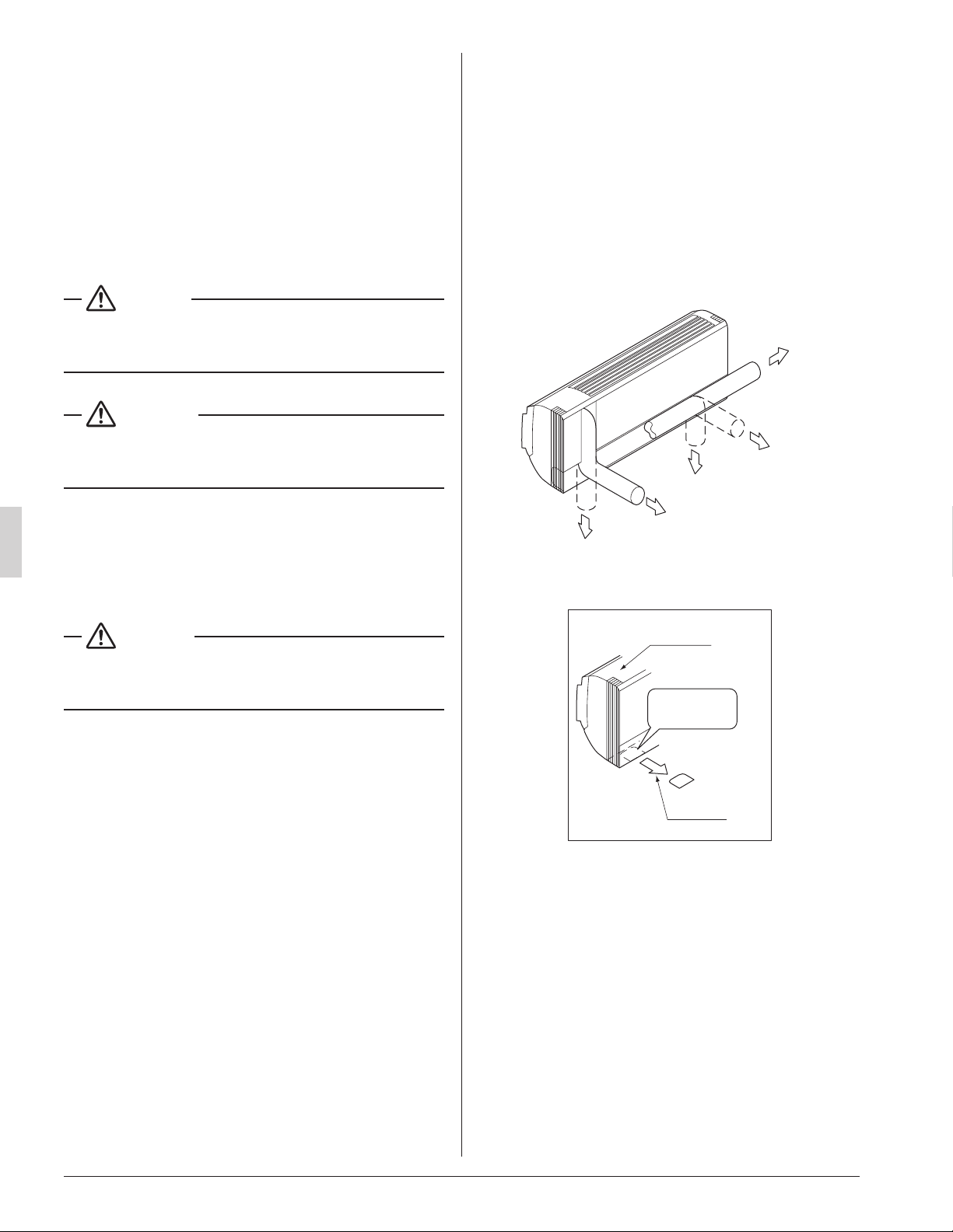
(1) Open the piping through-hole.
• The refrigerant pipe and drain pipe can be routed out
in one of 5 directions: left, bottom-left, back-left,
bottom-right, and back-right. (Refer to Fig. 3)
• Using the paper pattern for installation (3), choose
where to route the piping out of the unit, and drill a
through-hole (f3-1/8” (f80)) in the wall.
Open the hole so that there is a downward slope for
the drain piping. (See “6. DRAIN PIPING WORK”)
(2) Attach the installation panel (1) to the wall.
(a) Check the location for the hole using the included
paper pattern for installation (3).
• Choose a location so that there is at least a 3-5/8”
(90 mm) gap between the ceiling and the main
unit.
(b) Temporarily attach the installation panel (1) at the
temporary-securing position on the paper pattern for
installation (3) and use a level to make sure the drain
hose is either level or tilted slightly downward.
(c) Secure the installation panel (1) to the wall using
either screws or bolts.
• If using the attachment screws for the installation
panel (2), attach using at least 4 screws on either
side, for a total of 9 screws of the recommended
installation cleat position on the included paper
pattern for installation (3).
• If using bolts, attach using a M8 - M10 bolt or
equivalent (for a total of 2 bolts) on either side.
• If dealing with concrete, use commercially avail-
able foundation bolts (M8 - M10 or equivalent).
(3) If using the left, bottom-left, or bottom-right posi-
tions for the piping, cut out the through-hole for the
piping in the front grille. (Refer to Fig. 4)
Left pipe
Back-left pipe
Back-right pipe
Bottom-left pipe
Bottom-right pipe
Fig. 3
Front grille
Cut away
Fig. 4
Cut out along
the groove.
01_EN_3PN07521-5H.indd 5 7/9/2018 14:13:33
Loading ...
Loading ...
Loading ...