Loading ...
Loading ...
Loading ...
12
English
WARNING
• Never connect power supply wiring to the terminal block
for remote controller wiring as this could damage the
entire system.
• Use only specied wire and connect wires to the terminal
tightly. Be careful wires do not place external stress on
terminals. Keep wires in neat order so as not to obstruct
other equipment. Make sure that the control box cover ts
tightly. Incomplete connections could result in overheating
and, in worse case, result in electric shock or re.
• To avoid a short circuit in the control box, be sure to apply
sealing material or putty (not included) to the wiring hole
to prevent the inltration of water as well as insects or
other small creatures. Otherwise a short-circuit may occur
inside the control box.
CAUTION
• When clamping the wirings, be sure no tension is applied
to the wire connections by using the included clamp. Also,
when wiring, make sure the cover on the control box ts
snugly by arranging the wirings neatly and attaching the
control box cover rmly. When attaching the control box
cover, make sure no wirings get caught in the edges. Pass
wiring through holes to prevent damage to them.
• Make sure the remote controller wiring and transmission
wiring between the units, and other electrical wiring do not
pass through the same locations outside the unit, separat-
ing them by at least 2 in. (50 mm), otherwise electrical
noise (external static) could cause incorrect operation or
breakage.
[ PRECAUTIONS ]
1. Use round crimp-style terminals for connecting wires to
the power supply terminal block.
(Refer to Fig. 23)
If unavailable, observe the following points when wiring.
• Do not connect wires of different gauge to the same
power supply terminal.
(Looseness in the connection may cause overheat-
ing.)
• Use the specied electric wire. Connect the wire
securely to the terminal. Lock the wire down without
applying excessive force to the terminal.
Electric wire
Round crimp-style
terminal
Attach insulation sleeve
Fig. 23
2. Tightening torque for the terminal screws.
• Use the correct screwdriver for tightening the terminal
screws. If the blade of screwdriver is too small, the
head of the screw might be damaged, and the screw
will not be properly tightened.
• If the terminal screws are tightened too hard, screws
might be damaged.
• Refer to the table below for the tightening torque of
the terminal screws.
Terminal Size
Tightening torque
[lbf·ft. (N·m)]
Remote controller,
Transmission wiring and
Forced off terminal block (6P)
M3.5
0.59 – 0.71
(0.80 – 0.96)
Power supply and Ground
terminal block (3P)
M4
0.89 – 1.03
(1.2 – 1.4)
3. Do not connect wires of different gauge to the same
ground terminal. Looseness in the connection may
lessen protection.
4. Keep transmission wiring at least 2 in. (50 mm) away
from power supply wiring. The equipment may malfunc-
tion if subjected to electrical (external) noise.
5. For remote controller wiring, refer to the installation
manual attached to the remote controller.
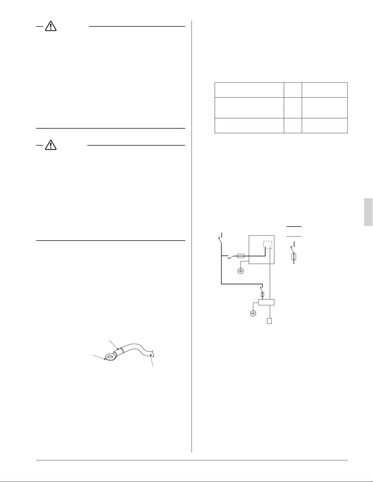
8-2 WIRING EXAMPLE
COMPLETE SYSTEM EXAMPLE
Power supply
Main
switch
Outdoor unit
Power supply wire
Transmission wire
Disconnect switch
Fuse/Breaker
Indoor unit
Remote controller
Fig. 24
01_EN_3PN07521-5H.indd 12 7/9/2018 14:13:35
Loading ...
Loading ...
Loading ...